OWNER’S MANUAL - seat.co.uk · ››› Booklet Navigation system Safety: Adaptive cruise...
308
OWNER’S MANUAL Arona
-
Upload
nguyendien -
Category
Documents
-
view
221 -
download
0
Transcript of OWNER’S MANUAL - seat.co.uk · ››› Booklet Navigation system Safety: Adaptive cruise...
OWNER’S MANUAL
Arona
6F9012720BA
Ingl
és 6
F901
2720
BA
(07
.17)
Aro
na
Ingl
és (
07.1
7)
SEAT recommendsSEAT GENUINE OIL
SEAT recommendsCastrol EDGE Professional

SEAT S.A. is permanently concerned about continuous development of its types and models. For this reason we ask you to under-stand, that at any given time, changes regarding shape, equipment and technique may take place on the car delivered. For this reason no right at all may derive based on the data, drawings and descriptions in this current handbook.
All texts, illustrations and standards in this handbook are based on the status of information at the time of printing. Except for error or omission, the information included in the current handbook is valid as of the date of closing print.
Re-printing, copying or translating, whether total or partial is not allowed unless SEAT allows it in written form.
SEAT reserves all rights in accordance with the “Copyright” Act.
All rights on changes are reserved.
❀ This paper has been manufactured using bleached non-chlorine cellulose.
© SEAT S.A. - Reprint: 15.07.17
About this manual
This manual contains a description of the equipment supplied with the vehicle at the time this manual was published. Some of the units described herein will not be available until a later date or are only available in cer-tain markets.
Because this is a general manual for the ARONA, some of the equipment and functions that are described in this manual are not in-cluded in all types or variants of the model; they may vary or be modified depending on the technical requirements and on the mar-ket; this is in no way deceptive advertising.
The illustrations are intended as a general guide and may vary from the equipment fitted in your vehicle in some details.
The steering indications (left, right, forward, reverse) appearing in this manual refer to the normal driving movements of the vehicle ex-cept when otherwise indicated.
The audiovisual material only is intended to help users to understand certain car function-alities better. It does not replace the instruc-tion manual. Please use the instruction manu-al to obtain more comprehensive information and indications.
The equipment marked with an aster-isk* is fitted as standard only in certain versions, and is only supplied as op-tional extras for some versions, or are only offered in certain countries.
® All registered marks are indicated with ®. Although the copyright symbol does not appear, it is a copyrighted mark.
>> The section is continued on the follow-ing page.
Important warnings on a given page
Detailed contents on a given page
General information on a given page
Emergency information on a given page
WARNING
Texts preceded by this symbol contain infor-mation on safety. They warn you about possi-ble dangers of accident or injury.
CAUTION
Texts with this symbol draw your attention to potential sources of damage to your vehicle.
For the sake of the environment
Texts preceded by this symbol contain rele-vant information concerning environmental protection.
Note
Texts preceded by this symbol contain additio-nal information.
This manual is divided into six large parts, which are:
1. The essentials
2. Safety
3. Emergencies
4. Operation
5. Tips
6. Technical data
At the end of this manual, there is a detailed alphabetical index that will help you quickly find the information you require.
ForewordThis Instruction Manual and its correspond-ing supplements should be read carefully tofamiliarise yourself with your vehicle.
Besides the regular care and maintenance ofthe vehicle, its correct handling will help pre-serve its value.
For safety reasons, always note the informa-tion concerning accessories, modificationsand part replacements.
If selling the vehicle, give all of the on-boarddocumentation to the new owner, as itshould be kept with the vehicle.
You can access the information in this man-ual using:
● Thematic table of contents that follows themanual’s general chapter structure.
● Visual table of contents that uses graphicsto indicate the pages containing “essential”information, which is detailed in the corre-sponding chapters.
● Alphabetical index with many terms andsynonyms to help you find information.
WARNING
Read and always observe safety informa-tion concerning the passenger's front air-bag ››› page 88, Important informationregarding the front passenger's airbag.
Thank you for trusting in us.
We wish you safe and enjoya-ble motoring.
SEAT, S.A.

Related videos
The essentials: Opening and clos-ing
››› page 15 The essentials: Vehicle interior››› page 18››› page 20››› page 23
The essentials: Bonnet ››› page 17 The essentials: Wheels››› page 60››› page 61
The essentials: Air conditioning ››› page 48 The essentials: Dash panel››› page 30››› page 42››› page 44
Convenience: Kessy keyless access and starting system, Full LED (+ Vision Pack): Full LED + Welcome light + LED day-time running lights + Lights sensor + LED interior lighting.
››› page 129››› page 140››› page 142››› page 196
Technology: SEAT Navi System Plus 8” + Full Link / + Wireless charger in centre console + / Kessy keyless access andstarting system.
››› page 123››› page 129››› Booklet Navigation system
Safety: Adaptive cruise control + City Safety Assist with pedestrian monitoring, fatigue detector, Hill driving assistantincludes on-board computer and rear view camera.
››› page 182››› page 209››› page 227››› page 242

Table of Contents
Table of ContentsThe essentials . . . . . . . . . . . . . . . . . . . . . . . . 7Exterior view . . . . . . . . . . . . . . . . . . . . . . . . . . . . 7Exterior view . . . . . . . . . . . . . . . . . . . . . . . . . . . . 8Driver-side general instrument panel (left-hand drive) . . . . . . . . . . . . . . . . . . . . . . . . . . . . . 9Driver-side general instrument panel (right-hand drive) . . . . . . . . . . . . . . . . . . . . . . . . . . . . . 10Centre console . . . . . . . . . . . . . . . . . . . . . . . . . . 11Passenger-side general instrument panel (left-hand drive) . . . . . . . . . . . . . . . . . . . . . . . . . . . . . 12Passenger-side general instrument panel(right-hand drive) . . . . . . . . . . . . . . . . . . . . . . . . 13Interior view . . . . . . . . . . . . . . . . . . . . . . . . . . . . 14How it works . . . . . . . . . . . . . . . . . . . . . . . . . . . . 15Opening and closing . . . . . . . . . . . . . . . . . . . . . 15Before driving . . . . . . . . . . . . . . . . . . . . . . . . . . . 18Airbags . . . . . . . . . . . . . . . . . . . . . . . . . . . . . . . . 20Child seats . . . . . . . . . . . . . . . . . . . . . . . . . . . . . 23Starting the vehicle . . . . . . . . . . . . . . . . . . . . . . 30Lights and visibility . . . . . . . . . . . . . . . . . . . . . . 30Easy Connect . . . . . . . . . . . . . . . . . . . . . . . . . . . 33Driver information system . . . . . . . . . . . . . . . . . 35Status display . . . . . . . . . . . . . . . . . . . . . . . . . . . 38Cruise control . . . . . . . . . . . . . . . . . . . . . . . . . . . 42Warning lamps . . . . . . . . . . . . . . . . . . . . . . . . . . 44Gearbox lever . . . . . . . . . . . . . . . . . . . . . . . . . . . 47Air conditioning . . . . . . . . . . . . . . . . . . . . . . . . . 48Fluid Level control . . . . . . . . . . . . . . . . . . . . . . . 54Emergencies . . . . . . . . . . . . . . . . . . . . . . . . . . . . 58Fuses . . . . . . . . . . . . . . . . . . . . . . . . . . . . . . . . . . 58Bulbs . . . . . . . . . . . . . . . . . . . . . . . . . . . . . . . . . . 59Action in the event of a puncture . . . . . . . . . . . 60Changing a wheel . . . . . . . . . . . . . . . . . . . . . . . 61Snow chains . . . . . . . . . . . . . . . . . . . . . . . . . . . . 66Emergency towing of the vehicle . . . . . . . . . . . 66
How to jump start . . . . . . . . . . . . . . . . . . . . . . . . 67Changing the windscreen wiper blades . . . . . . 69
Safety . . . . . . . . . . . . . . . . . . . . . . . . . . . . . . . . 71Safe driving . . . . . . . . . . . . . . . . . . . . . . . . . . . . 71Safety first! . . . . . . . . . . . . . . . . . . . . . . . . . . . . . 71Advice about driving . . . . . . . . . . . . . . . . . . . . . 71Correct position for passengers . . . . . . . . . . . . 72Pedal area . . . . . . . . . . . . . . . . . . . . . . . . . . . . . . 76Seat belts . . . . . . . . . . . . . . . . . . . . . . . . . . . . . . 77Why wear a seat belt? . . . . . . . . . . . . . . . . . . . . 77How to properly adjust your seatbelt . . . . . . . . 80Belt pretensioners* . . . . . . . . . . . . . . . . . . . . . . 81Airbag system . . . . . . . . . . . . . . . . . . . . . . . . . . 82Brief introduction . . . . . . . . . . . . . . . . . . . . . . . . 82Airbag safety instructions . . . . . . . . . . . . . . . . . 84Deactivating airbags . . . . . . . . . . . . . . . . . . . . . 86Transporting children safely . . . . . . . . . . . . . . . 88Safety for children . . . . . . . . . . . . . . . . . . . . . . . 88Child seats . . . . . . . . . . . . . . . . . . . . . . . . . . . . . 89Event Data Recorder . . . . . . . . . . . . . . . . . . . . . . 92Description and operation . . . . . . . . . . . . . . . . . 92
Emergencies . . . . . . . . . . . . . . . . . . . . . . . . . . 93Self-help . . . . . . . . . . . . . . . . . . . . . . . . . . . . . . . 93Emergency equipment . . . . . . . . . . . . . . . . . . . . 93Tyre repair . . . . . . . . . . . . . . . . . . . . . . . . . . . . . . 94Changing the windscreen wiper blades . . . . . . 96Towing or tow-starting . . . . . . . . . . . . . . . . . . . . 96Fuses and bulbs . . . . . . . . . . . . . . . . . . . . . . . . . 100Fuses . . . . . . . . . . . . . . . . . . . . . . . . . . . . . . . . . . 100Changing bulbs . . . . . . . . . . . . . . . . . . . . . . . . . 102Change the front bulbs . . . . . . . . . . . . . . . . . . . 103Change the rear bulbs . . . . . . . . . . . . . . . . . . . . 105Changing the interior bulbs . . . . . . . . . . . . . . . . 107
Operation . . . . . . . . . . . . . . . . . . . . . . . . . . . . . 111Controls and displays . . . . . . . . . . . . . . . . . . . . 111General instrument panel . . . . . . . . . . . . . . . . . 110
Instruments and warning/control lamps . . . . . 113Instruments . . . . . . . . . . . . . . . . . . . . . . . . . . . . 113Warning and control lamps . . . . . . . . . . . . . . . . 117Introduction to the Easy Connect system* . . . . 118System settings (CAR)* . . . . . . . . . . . . . . . . . . . 118Communications and multimedia . . . . . . . . . . . 119Steering wheel controls* . . . . . . . . . . . . . . . . . . 119Multimedia . . . . . . . . . . . . . . . . . . . . . . . . . . . . . 123Opening and closing . . . . . . . . . . . . . . . . . . . . . 124Keys . . . . . . . . . . . . . . . . . . . . . . . . . . . . . . . . . . . 124Central locking system . . . . . . . . . . . . . . . . . . . . 126Anti-theft alarm* . . . . . . . . . . . . . . . . . . . . . . . . 132Boot hatch . . . . . . . . . . . . . . . . . . . . . . . . . . . . . 135Electric windows . . . . . . . . . . . . . . . . . . . . . . . . . 135Lights and visibility . . . . . . . . . . . . . . . . . . . . . . 137Lights . . . . . . . . . . . . . . . . . . . . . . . . . . . . . . . . . 137Interior lights . . . . . . . . . . . . . . . . . . . . . . . . . . . 142Visibility . . . . . . . . . . . . . . . . . . . . . . . . . . . . . . . 143Windscreen wiper and rear window wiper sys-tems . . . . . . . . . . . . . . . . . . . . . . . . . . . . . . . . . . 143Rear view mirrors . . . . . . . . . . . . . . . . . . . . . . . . 144Seats and head restraints . . . . . . . . . . . . . . . . . 146Adjusting the seat and head restraints . . . . . . 146Seat functions . . . . . . . . . . . . . . . . . . . . . . . . . . 147Transport and practical equipment . . . . . . . . . 150Practical equipment . . . . . . . . . . . . . . . . . . . . . . 150Luggage compartment . . . . . . . . . . . . . . . . . . . . 152Roof carrier* . . . . . . . . . . . . . . . . . . . . . . . . . . . . 156Air conditioning . . . . . . . . . . . . . . . . . . . . . . . . . 158Heating, ventilation and cooling . . . . . . . . . . . . 158Heating and fresh air . . . . . . . . . . . . . . . . . . . . . 161Manual air conditioning* . . . . . . . . . . . . . . . . . . 163Climatronic* . . . . . . . . . . . . . . . . . . . . . . . . . . . . 165Driving . . . . . . . . . . . . . . . . . . . . . . . . . . . . . . . . 167Address . . . . . . . . . . . . . . . . . . . . . . . . . . . . . . . . 167Starting and stopping the engine . . . . . . . . . . . 168Braking and parking . . . . . . . . . . . . . . . . . . . . . 174Braking and stability systems . . . . . . . . . . . . . . 177
5

Table of Contents
Manual gearbox . . . . . . . . . . . . . . . . . . . . . . . . . 183Automatic gearbox/DSG automatic gear-box* . . . . . . . . . . . . . . . . . . . . . . . . . . . . . . . . . . . 183Gear-change indicator . . . . . . . . . . . . . . . . . . . . 190Run-in and economical driving . . . . . . . . . . . . . 191Engine management and exhaust gas purifica-tion system . . . . . . . . . . . . . . . . . . . . . . . . . . . . . 193Driving tips . . . . . . . . . . . . . . . . . . . . . . . . . . . . . 195Driver assistance systems . . . . . . . . . . . . . . . . . 196Start-Stop System* . . . . . . . . . . . . . . . . . . . . . . . 196Cruise control system (CCS)* . . . . . . . . . . . . . . . 198Speed limiter . . . . . . . . . . . . . . . . . . . . . . . . . . . 200Area monitoring system (Front Assist) includ-ing City emergency braking and pedestrianmonitoring* . . . . . . . . . . . . . . . . . . . . . . . . . . . . 203Adaptive Cruise Control ACC* . . . . . . . . . . . . . . 209Blind spot detector (BSD) with parking assis-tance (RCTA)* . . . . . . . . . . . . . . . . . . . . . . . . . . . 220SEAT Drive Profile* . . . . . . . . . . . . . . . . . . . . . . . 225Fatigue detection (break recommendation)* . . 227Park Assist* . . . . . . . . . . . . . . . . . . . . . . . . . . . . 228Parking aid . . . . . . . . . . . . . . . . . . . . . . . . . . . . . 236Rear Assist “Rear View Camera”* . . . . . . . . . . . 242Towing bracket device . . . . . . . . . . . . . . . . . . . . 245Towing bracket device* . . . . . . . . . . . . . . . . . . . 245Trailer towing . . . . . . . . . . . . . . . . . . . . . . . . . . . 250
Advice . . . . . . . . . . . . . . . . . . . . . . . . . . . . . . . . 255Care and maintenance . . . . . . . . . . . . . . . . . . . . 255Accessories and modifications to the vehi-cle . . . . . . . . . . . . . . . . . . . . . . . . . . . . . . . . . . . . 255Care and cleaning . . . . . . . . . . . . . . . . . . . . . . . 256Care of the vehicle exterior . . . . . . . . . . . . . . . . 257Caring for the vehicle interior . . . . . . . . . . . . . . 262Checking and refilling levels . . . . . . . . . . . . . . . 265Refuelling . . . . . . . . . . . . . . . . . . . . . . . . . . . . . . 265Fuel . . . . . . . . . . . . . . . . . . . . . . . . . . . . . . . . . . . 265Working in the engine compartment . . . . . . . . 267
Engine oil . . . . . . . . . . . . . . . . . . . . . . . . . . . . . . 270Cooling system . . . . . . . . . . . . . . . . . . . . . . . . . . 273Brake fluid . . . . . . . . . . . . . . . . . . . . . . . . . . . . . 275Windscreen washer reservoir . . . . . . . . . . . . . . 276Vehicle battery . . . . . . . . . . . . . . . . . . . . . . . . . . 276Wheels . . . . . . . . . . . . . . . . . . . . . . . . . . . . . . . . 278Wheels and tyres . . . . . . . . . . . . . . . . . . . . . . . . 278Spare wheel (temporary spare wheel)* . . . . . . 283Winter service . . . . . . . . . . . . . . . . . . . . . . . . . . . 284
Technical data . . . . . . . . . . . . . . . . . . . . . . . . 285Technical specifications . . . . . . . . . . . . . . . . . . 285Important information . . . . . . . . . . . . . . . . . . . . 285Information on fuel consumption . . . . . . . . . . . 286Trailer mode . . . . . . . . . . . . . . . . . . . . . . . . . . . . 286Wheels . . . . . . . . . . . . . . . . . . . . . . . . . . . . . . . . 287Engine data . . . . . . . . . . . . . . . . . . . . . . . . . . . . . 288Dimensions . . . . . . . . . . . . . . . . . . . . . . . . . . . . . 290
Index . . . . . . . . . . . . . . . . . . . . . . . . . . . . . . . . . 293
6
The essentials
Exterior view
››› page 16
››› page 54
››› page 15
››› page 54
1
2
3
4
››› page 66
››› page 17
››› page 60
5
6
7
7

The essentials
Exterior view
››› page 56
››› page 55
››› page 57
››› page 58
1
2
3
4
››› page 55
››› page 57
››› page 57
››› page 154
5
6
7
8
››› page 29
››› page 61
››› page 60
9
10
11
8
The essentials
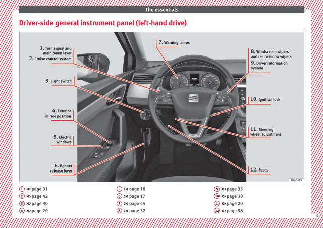
Driver-side general instrument panel (left-hand drive)
››› page 31
››› page 42
››› page 30
››› page 20
1
2
3
4
››› page 18
››› page 17
››› page 44
››› page 32
5
6
7
8
››› page 35
››› page 30
››› page 20
››› page 58
9
10
11
12
9
The essentials
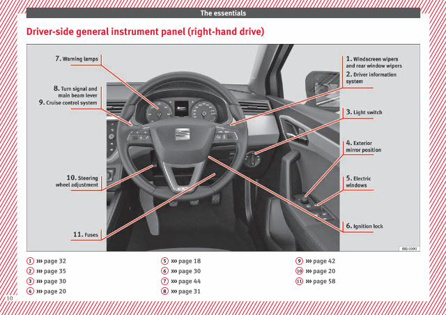
Driver-side general instrument panel (right-hand drive)
››› page 32
››› page 35
››› page 30
››› page 20
1
2
3
4
››› page 18
››› page 30
››› page 44
››› page 31
5
6
7
8
››› page 42
››› page 20
››› page 58
9
10
11
10
The essentials
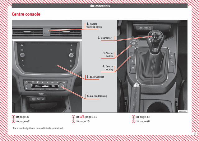
Centre console
››› page 31
››› page 47
1
2
››› page 171
››› page 15
3
4
››› page 33
››› page 48
5
6
The layout in right-hand drive vehicles is symmetrical.
11

The essentials
Passenger-side general instrument panel (left-hand drive)
››› page 20
››› page 18
››› page 150
1
2
3
12

The essentials
Passenger-side general instrument panel (right-hand drive)
››› page 20
››› page 18
››› page 17
››› page 150
1
2
3
413

The essentials
Interior view
››› page 19
››› page 19
››› page 144
››› page 26
1
2
3
4
››› page 18
››› page 21
5
6
14

The essentials
How it works
Opening and closing
Related video
Fig. 1 Opening and clos-ing
Doors
Fig. 2 Remote control key: buttons.
Fig. 3 Centre console: Central lock buttons.
Locking and unlocking the vehicle using thekey
● Locking: press the ››› Fig. 2 button.
● Unlocking: press the ››› Fig. 2 button.
● Unlocking the rear lid: press the ››› Fig. 2 button until all the turn signals onthe vehicle briefly light up.
Locking and unlocking with the central lock-ing switch
● Locking: press the ››› Fig. 3 button. The symbol lights up yellow to indicate that it isactivated. None of the doors can be openedfrom the outside. The doors can be openedfrom the inside by pulling the inside doorhandle.
● Unlocking: press the ››› Fig. 3 buttonagain. The symbol reverts to its initial colour.
››› in Description on page 126
››› page 126
Unlocking or locking of driver door
Fig. 4 Driver door lever: hidden lock cylinder.
If the central locking system should fail to op-erate, the driver door can still be locked andunlocked by turning the key in the lock.
As a general rule, when the driver door islocked manually all other doors are locked.When it is unlocked manually, only the driverdoor opens. Please observe the instructionsrelating to the anti-theft alarm system››› page 132.
● Unfold the vehicle key blade››› page 124. »
15
The essentials
● Insert the key shaft into the lower openingin the cover on the driver door handle››› Fig. 4 (arrow) then remove the cover up-wards.
● Insert the key blade into the lock cylinderto unlock or lock the vehicle.
Special Characteristics
● The anti-theft alarm will remain active whenvehicles are unlocked. However, the alarmwill not be triggered ››› page 132.
● After the driver door is opened, you have15 seconds to switch on the ignition. Oncethis time has elapsed, the alarm is triggered.
● Switch the ignition on. The electronic im-mobilizer recognises a valid vehicle key anddeactivates the anti-theft alarm system.
Note
The anti-theft alarm is not activated when thevehicle is locked manually using the keyshaft ››› page 132.
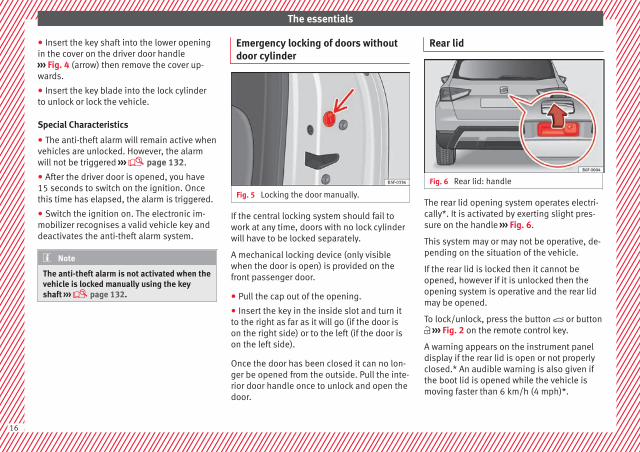
Emergency locking of doors withoutdoor cylinder
Fig. 5 Locking the door manually.
If the central locking system should fail towork at any time, doors with no lock cylinderwill have to be locked separately.
A mechanical locking device (only visiblewhen the door is open) is provided on thefront passenger door.
● Pull the cap out of the opening.
● Insert the key in the inside slot and turn itto the right as far as it will go (if the door ison the right side) or to the left (if the door ison the left side).
Once the door has been closed it can no lon-ger be opened from the outside. Pull the inte-rior door handle once to unlock and open thedoor.
Rear lid
Fig. 6 Rear lid: handle
The rear lid opening system operates electri-cally*. It is activated by exerting slight pres-sure on the handle ››› Fig. 6.
This system may or may not be operative, de-pending on the situation of the vehicle.
If the rear lid is locked then it cannot beopened, however if it is unlocked then theopening system is operative and the rear lidmay be opened.
To lock/unlock, press the button or button ››› Fig. 2 on the remote control key.
A warning appears on the instrument paneldisplay if the rear lid is open or not properlyclosed.* An audible warning is also given ifthe boot lid is opened while the vehicle ismoving faster than 6 km/h (4 mph)*.
16
The essentials
● Opening the rear lid: exert slight pressureon the handle ››› Fig. 6. The rear lid opens au-tomatically.
● Closing the rear lid: hold it by one of thehandles on the interior lining and close it bypushing gently.
››› in Opening and closing onpage 135
››› page 17
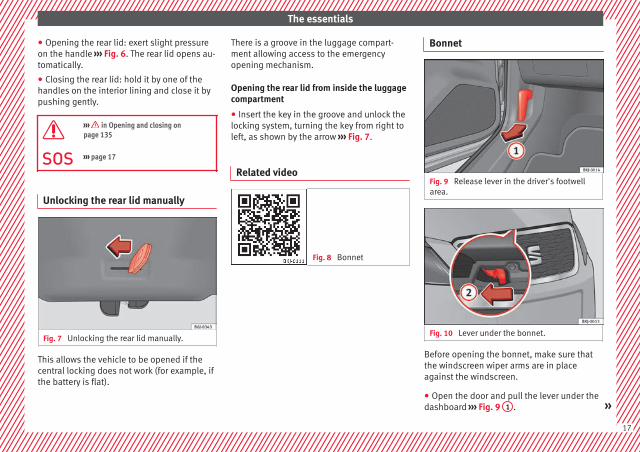
Unlocking the rear lid manually
Fig. 7 Unlocking the rear lid manually.
This allows the vehicle to be opened if thecentral locking does not work (for example, ifthe battery is flat).
There is a groove in the luggage compart-ment allowing access to the emergencyopening mechanism.
Opening the rear lid from inside the luggagecompartment
● Insert the key in the groove and unlock thelocking system, turning the key from right toleft, as shown by the arrow ››› Fig. 7.
Related video
Fig. 8 Bonnet
Bonnet
Fig. 9 Release lever in the driver's footwellarea.
Fig. 10 Lever under the bonnet.
Before opening the bonnet, make sure thatthe windscreen wiper arms are in placeagainst the windscreen.
● Open the door and pull the lever under thedashboard ››› Fig. 9 1 . »
17
The essentials
● To lift the bonnet, press towards the left onthe lever located under the bonnet, in thecentre ››› Fig. 10 2 . The arrester hooks arereleased.
● Release the bonnet stay and secure it inthe fixture designed for this in the bonnet.
››› in safety notes for work in the en-gine compartment on page 267
››› page 267
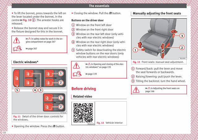
Electric windows*
Fig. 11 Detail of the driver door: controls forthe windows.
● Opening the window: Press the button.
● Closing the window: Pull the button.
Buttons on the driver door
Window on the front left door
Window on the front right door
Window on the rear left door (only vehi-cles with rear electric windows)
Window on the rear right door (only vehi-cles with rear electric windows)
Safety switch for deactivating the electricwindow buttons on the rear doors (onlyvehicles with rear electric windows)
››› in Opening and closing of the elec-tric windows* on page 135
››› page 135
Before driving
Related video
Fig. 12 Vehicle interior
1
2
3
4
5
Manually adjusting the front seats
Fig. 13 Front seats: manual seat adjustment.
Forward/back: pull the lever and movethe seat forwards or backwards.
Raising/lowering: pull/push the lever.
Tilting the backrest: turn the hand wheel.
››› in Adjusting the front seats onpage 146
1
2
3
18

The essentials
Adjusting the head restraints
Fig. 14 Front seat: adjustment of the head re-straint.
● To raise or lower the head restraint, pressthe side button 1 and move it upwards ordownwards until it engages in the desiredposition.
››› in Adjusting the front head re-straints on page 146
››› page 75, ››› page 146
Adjustment of the seat belt
Fig. 15 Positioning and removing the seatbelt buckle.
Fig. 16 Correct seat belt and head restraintpositions, viewed from front and the side.
To adjust the seat belt around your should-ers, adjust the height of the seats.
The shoulder part of the seat belt should bewell centred over it, never over the neck. Theseat belt lies flat and fits comfortably on theupper part of the body.
The lap part of the seat belt lies across thepelvis, never across the stomach. The seatbelt lies flat and fits comfortably on the pel-vis.
››› page 78
››› page 80
19
The essentials
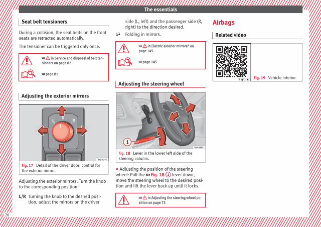
Seat belt tensioners
During a collision, the seat belts on the frontseats are retracted automatically.
The tensioner can be triggered only once.
››› in Service and disposal of belt ten-sioners on page 82
››› page 81
Adjusting the exterior mirrors
Fig. 17 Detail of the driver door: control forthe exterior mirror.
Adjusting the exterior mirrors: Turn the knobto the corresponding position:
Turning the knob to the desired posi-tion, adjust the mirrors on the driver
L/R
side (L, left) and the passenger side (R,right) to the direction desired.
Folding in mirrors.
››› in Electric exterior mirrors* onpage 145
››› page 145
Adjusting the steering wheel
Fig. 18 Lever in the lower left side of thesteering column.
● Adjusting the position of the steeringwheel: Pull the ››› Fig. 18 1 lever down,move the steering wheel to the desired posi-tion and lift the lever back up until it locks.
››› in Adjusting the steering wheel po-sition on page 73
Airbags
Related video
Fig. 19 Vehicle interior
20
The essentials
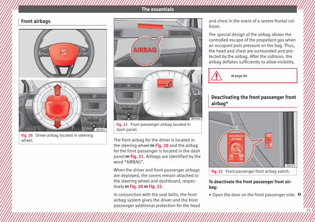
Front airbags
Fig. 20 Driver airbag located in steeringwheel.
Fig. 21 Front passenger airbag located indash panel.
The front airbag for the driver is located inthe steering wheel ››› Fig. 20 and the airbagfor the front passenger is located in the dashpanel ››› Fig. 21. Airbags are identified by theword “AIRBAG”.
When the driver and front passenger airbagsare deployed, the covers remain attached tothe steering wheel and dashboard, respec-tively ››› Fig. 20 ››› Fig. 21.
In conjunction with the seat belts, the frontairbag system gives the driver and the frontpassenger additional protection for the head
and chest in the event of a severe frontal col-lision.
The special design of the airbag allows thecontrolled escape of the propellant gas whenan occupant puts pressure on the bag. Thus,the head and chest are surrounded and pro-tected by the airbag. After the collision, theairbag deflates sufficiently to allow visibility.
››› page 84
Deactivating the front passenger frontairbag*
Fig. 22 Front passenger front airbag switch.
To deactivate the front passenger front air-bag:
● Open the door on the front passenger side. »
21
The essentials
● Insert the key blade into the slot providedin the deactivation switch.
● Approximately ¾ of the length of the keyblade remains inserted (the maximum).
● Turn the key blade, changing its position to. Do not force it. If you have difficulty, en-sure that you have inserted the key as far asit will go.
● Finally, check the control lamp on the in-strument panel where it shows the following should appear .
››› in Deactivation of front passengerfront airbag* on page 87
››› page 86
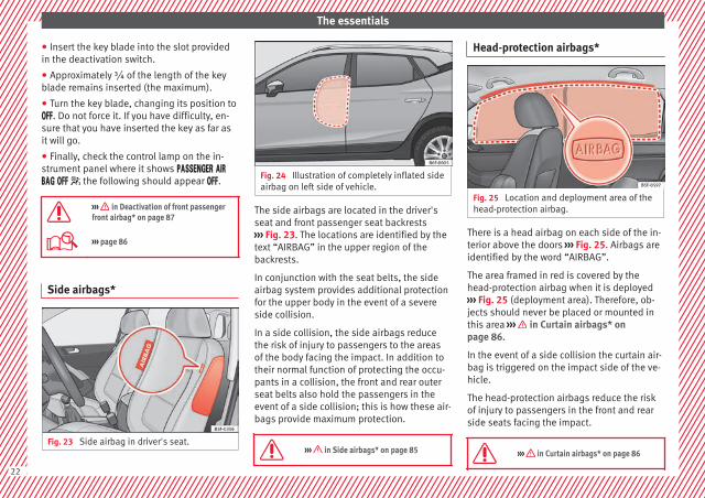
Side airbags*
Fig. 23 Side airbag in driver's seat.
Fig. 24 Illustration of completely inflated sideairbag on left side of vehicle.
The side airbags are located in the driver'sseat and front passenger seat backrests››› Fig. 23. The locations are identified by thetext “AIRBAG” in the upper region of thebackrests.
In conjunction with the seat belts, the sideairbag system provides additional protectionfor the upper body in the event of a severeside collision.
In a side collision, the side airbags reducethe risk of injury to passengers to the areasof the body facing the impact. In addition totheir normal function of protecting the occu-pants in a collision, the front and rear outerseat belts also hold the passengers in theevent of a side collision; this is how these air-bags provide maximum protection.
››› in Side airbags* on page 85
Head-protection airbags*
Fig. 25 Location and deployment area of thehead-protection airbag.
There is a head airbag on each side of the in-terior above the doors ››› Fig. 25. Airbags areidentified by the word “AIRBAG”.
The area framed in red is covered by thehead-protection airbag when it is deployed››› Fig. 25 (deployment area). Therefore, ob-jects should never be placed or mounted inthis area ››› in Curtain airbags* onpage 86.
In the event of a side collision the curtain air-bag is triggered on the impact side of the ve-hicle.
The head-protection airbags reduce the riskof injury to passengers in the front and rearside seats facing the impact.
››› in Curtain airbags* on page 86
22
The essentials
Child seats
Related video
Fig. 26 Vehicle interior
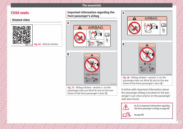
Important information regarding thefront passenger's airbag
Fig. 27 Airbag stickers - version 1: on thepassenger-side sun blind and on the rearframe of the front passenger's door .
Fig. 28 Airbag stickers - version 2: on thepassenger-side sun blind and on the rearframe of the front passenger's door .
A sticker with important information aboutthe passenger airbag is located on the pas-senger's sun visor and/or on the passengerside door frame.
››› in Important information regardingthe front passenger's airbag on page 88
››› page 88
23
The essentials
Securing child seats
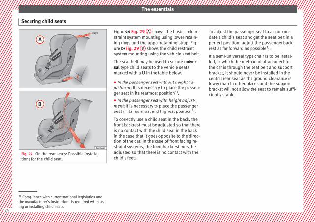
Fig. 29 On the rear seats: Possible installa-tions for the child seat.
Figure ››› Fig. 29 A shows the basic child re-straint system mounting using lower retain-ing rings and the upper retaining strap. Fig-ure ››› Fig. 29 B shows the child restraintsystem mounting using the vehicle seat belt.
The seat belt may be used to secure univer-sal type child seats to the vehicle seatsmarked with a U in the table below.
● In the passenger seat without height ad-justment: It is necessary to place the passen-ger seat in its rearmost position1).
● In the passenger seat with height adjust-ment: It is necessary to place the passengerseat in its rearmost and highest position1).
To correctly use a child seat in the back, thefront backrest must be adjusted so that thereis no contact with the child seat in the backin the case that it goes opposite to the direc-tion of the car. In the case of front facing re-straint systems, the front backrest must beadjusted so that there is no contact with thechild's feet.
To adjust the passenger seat to accommo-date a child's seat and get the seat belt in aperfect position, adjust the passenger back-rest as far forward as possible1).
If a semi-universal type chair is to be instal-led, in which the method of attachment tothe car is through the seat belt and supportbracket, it should never be installed in thecentral rear seat as the ground clearance islower than in other places and the supportbracket will not allow the seat to remain suffi-ciently stable.
1) Compliance with current national legislation andthe manufacturer's instructions is required when us-ing or installing child seats.
24
The essentials
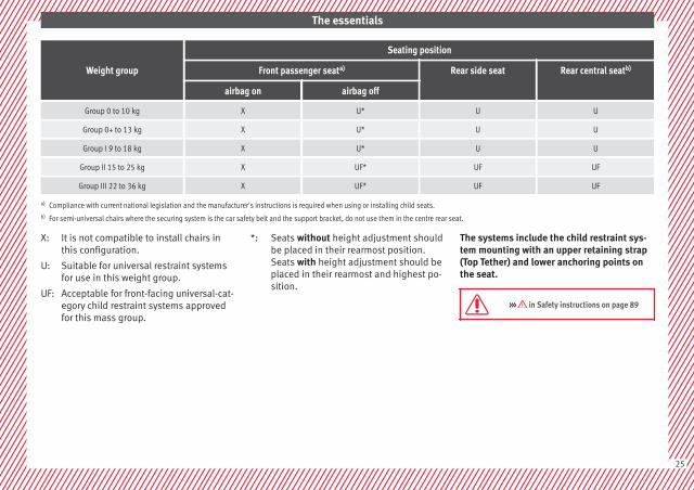
Weight group
Seating position
Front passenger seata) Rear side seat Rear central seatb)
airbag on airbag off
Group 0 to 10 kg X U* U U
Group 0+ to 13 kg X U* U U
Group I 9 to 18 kg X U* U U
Group II 15 to 25 kg X UF* UF UF
Group III 22 to 36 kg X UF* UF UF
a) Compliance with current national legislation and the manufacturer's instructions is required when using or installing child seats.b) For semi-universal chairs where the securing system is the car safety belt and the support bracket, do not use them in the centre rear seat.
It is not compatible to install chairs inthis configuration.
Suitable for universal restraint systemsfor use in this weight group.
Acceptable for front-facing universal-cat-egory child restraint systems approvedfor this mass group.
X:
U:
UF:
Seats without height adjustment shouldbe placed in their rearmost position.Seats with height adjustment should beplaced in their rearmost and highest po-sition.
*: The systems include the child restraint sys-tem mounting with an upper retaining strap(Top Tether) and lower anchoring points onthe seat.
››› in Safety instructions on page 89
25

The essentials
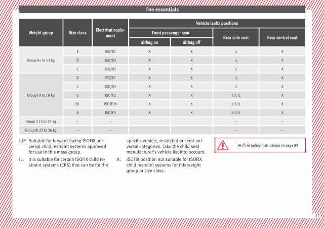
Securing child seats with the ISOFIX/iSize and Top Tether system*
Fig. 30 ISOFIX/iSize securing rings. Fig. 31 Position of the Top Tether rings on theback of the rear seat.
Child seats can be secured quickly, easilyand safely on the rear outer seats with the“ISOFIX” and Top Tether* system.
Two “ISOFIX” retaining rings are fitted oneach rear seat. In some vehicles, the ringsare secured to the seat frame and, in others,they are secured to the rear floor. The “ISO-
FIX” rings are located between the rear seatbackrest and the seat cushioning ››› Fig. 30.The Top Tether* rings are located on the rearpart of the backrests of the rear seats (be-hind the seat backrest or in the boot)››› Fig. 31.
To understand the compatibility of the "ISO-FIX" systems in the vehicle, consult the tablebelow.
The body weight permitted and informationregarding sizes A to F is indicated on the la-bel on child seats with “universal” or “semi-universal” certification.
Weight group Size classElectrical equip-
ment
Vehicle Isofix positions
Front passenger seatRear side seat Rear central seat
airbag on airbag off
Baby carrierF ISO/L1 X X X X
G ISO/L2 X X X X
Group 0 to 10 kg E ISO/R1 X X IL X
26
The essentials
Weight group Size classElectrical equip-
ment
Vehicle Isofix positions
Front passenger seatRear side seat Rear central seat
airbag on airbag off
Group 0+ to 13 kg
E ISO/R1 X X IL X
D ISO/R2 X X IL X
C ISO/R3 X X IL X
Group I 9 to 18 kg
D ISO/R2 X X IL X
C ISO/R3 X X IL X
B ISO/F2 X X IUF/IL X
B1 ISO/F2X X X IUF/IL X
A ISO/F3 X X IUF/IL X
Group II 15 to 25 kg --- --- --- ---
Group III 22 to 36 kg --- --- --- ---
Suitable for forward-facing ISOFIX uni-versal child restraint systems approvedfor use in this mass group.
It is suitable for certain ISOFIX child re-straint systems (CRS) that can be for the
IUF:
IL:
specific vehicle, restricted or semi-uni-versal categories. Take the child seatmanufacturer's vehicle list into account.
ISOFIX position not suitable for ISOFIXchild restraint systems for this weightgroup or size class.
X:
››› in Safety instructions on page 89
27
The essentials
Securing child seats with the “ISOFIX/i-Size” ISOFIX System
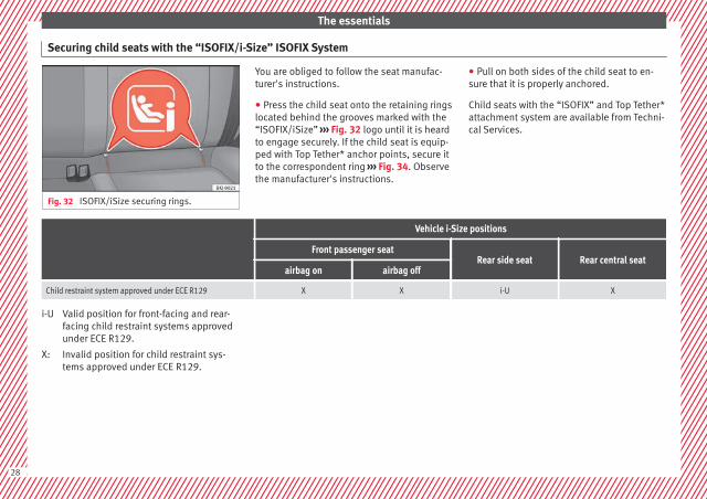
Fig. 32 ISOFIX/iSize securing rings.
You are obliged to follow the seat manufac-turer's instructions.
● Press the child seat onto the retaining ringslocated behind the grooves marked with the“ISOFIX/iSize” ››› Fig. 32 logo until it is heardto engage securely. If the child seat is equip-ped with Top Tether* anchor points, secure itto the correspondent ring ››› Fig. 34. Observethe manufacturer's instructions.
● Pull on both sides of the child seat to en-sure that it is properly anchored.
Child seats with the “ISOFIX” and Top Tether*attachment system are available from Techni-cal Services.
Vehicle i-Size positions
Front passenger seatRear side seat Rear central seat
airbag on airbag off
Child restraint system approved under ECE R129 X X i-U X
Valid position for front-facing and rear-facing child restraint systems approvedunder ECE R129.
Invalid position for child restraint sys-tems approved under ECE R129.
i-U
X:
28
The essentials
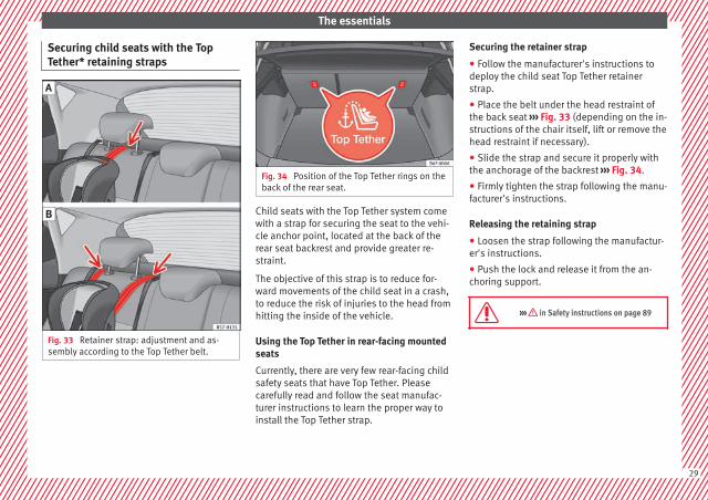
Securing child seats with the TopTether* retaining straps
Fig. 33 Retainer strap: adjustment and as-sembly according to the Top Tether belt.
Fig. 34 Position of the Top Tether rings on theback of the rear seat.
Child seats with the Top Tether system comewith a strap for securing the seat to the vehi-cle anchor point, located at the back of therear seat backrest and provide greater re-straint.
The objective of this strap is to reduce for-ward movements of the child seat in a crash,to reduce the risk of injuries to the head fromhitting the inside of the vehicle.
Using the Top Tether in rear-facing mountedseats
Currently, there are very few rear-facing childsafety seats that have Top Tether. Pleasecarefully read and follow the seat manufac-turer instructions to learn the proper way toinstall the Top Tether strap.
Securing the retainer strap
● Follow the manufacturer's instructions todeploy the child seat Top Tether retainerstrap.
● Place the belt under the head restraint ofthe back seat ››› Fig. 33 (depending on the in-structions of the chair itself, lift or remove thehead restraint if necessary).
● Slide the strap and secure it properly withthe anchorage of the backrest ››› Fig. 34.
● Firmly tighten the strap following the manu-facturer's instructions.
Releasing the retaining strap
● Loosen the strap following the manufactur-er's instructions.
● Push the lock and release it from the an-choring support.
››› in Safety instructions on page 89
29
The essentials
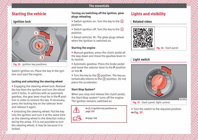
Starting the vehicle
Ignition lock
Fig. 35 Ignition key positions.
Switch ignition on: Place the key in the igni-tion and start the engine.
Locking and unlocking the steering wheel
● Engaging the steering wheel lock: Removethe key from the ignition and turn the wheeluntil it locks. In vehicles with an automaticgearbox, the gear lever must be in the P posi-tion in order to remove the key. If necessary,press the locking key on the selector leverand release it again.
● Unlocking the steering wheel: Put the keyinto the ignition and turn it at the same timeas the steering wheel in the direction indica-ted by the arrow. If it is not possible to turnthe steering wheel, it may be because it islocked.
Turning on/switching off the ignition, glowplugs reheating
● Switch ignition on: Turn the key to the 2
position.
● Switch ignition off. Turn the key to the 1
position.
● Diesel vehicles : The glow plugs reheatwhen the ignition is switched on.
Starting the engine
● Manual gearbox: press the clutch pedal allthe way down and move the gearbox lever in-to neutral.
● Automatic gearbox: Press the brake pedaland move the selector lever to the P positionor into N.
● Turn the key to the 3 position. The key au-tomatically returns to the 2 position. Do notpress the accelerator.
Start-Stop System*
When you stop and release the clutch pedal,the Start-Stop system* turns off the engine.The ignition remains switched on.
››› in Ignition key positions onpage 169
››› page 168
Lights and visibility
Related video
Fig. 36 Dash panel
Light switch
Fig. 37 Dash panel: light control.
● Turn the switch to the required position››› Fig. 37.
30
The essentials
SymbolIgnition switch-ed off
Ignition is switch-ed on
Fog lights, dippedbeam and sidelights off.
Light off or daytimedriving light on.
The “Cominghome” and “Leav-ing home” guidelights may beswitched on.
Automatic control ofdipped beam anddaytime runninglight.
Side light on.Daylight runninglights switched on.
Dipped beamheadlight off
Dipped beam switch-ed on.
Front fog lights: move the switch to thefirst position, from positions , or .
Rear fog light: move the switch completelyfrom positions , or .
Switching off fog lights: Push the switch orturn it to the position.
››› page 138
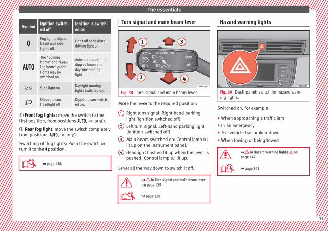
Turn signal and main beam lever
Fig. 38 Turn signal and main beam lever.
More the lever to the required position:
Right turn signal: Right-hand parkinglight (ignition switched off).
Left turn signal: Left-hand parking light(ignition switched off).
Main beam switched on: Control lamp lit up on the instrument panel.
Headlight flasher: lit up when the lever ispushed. Control lamp lit up.
Lever all the way down to switch it off.
››› in Turn signal and main beam leveron page 139
››› page 139
1
2
3
4
Hazard warning lights
Fig. 39 Dash panel: switch for hazard warn-ing lights.
Switched on, for example:
● When approaching a traffic jam
● In an emergency
● The vehicle has broken down
● When towing or being towed
››› in Hazard warning lights onpage 142
››› page 141
31

The essentials
Interior lights
Fig. 40 Detail of headliner: front interior light-ing.
Knob Function
Turning the interior lights on or off.
Activating or deactivating the automaticdoor contact lights.The interior lights come on automaticallywhen the vehicle is unlocked, a door isopened or the key is removed from theignition.The light goes off a few seconds after allthe doors are closed, the vehicle islocked or the ignition is switched on.
/ Turning the reading light on and off
The light controls may vary depending on thevehicle version.
››› page 142
Windscreen wipers and window wiperblade
Fig. 41 Operating the windscreen wiper andrear wiper.
More the lever to the required position:
0 Windscreen wiper off.
More the lever to the required position:
1
Windscreen wipers interval wipe.Using the control ››› Fig. 41 A adjust theinterval (vehicles without rain sensor), orthe sensitivity of the rain sensor.
2 Slow wipe.
3 Continuous wipe.
4 Short wipe. Brief press, short clean.
5
Automatic wipe. The windscreen washerfunction is activated by pushing the leverforwards, and simultaneously the wind-screen wipers start.
6 Interval wipe for rear window. The wiperwill wipe the window approximately everysix seconds.
7 The rear window wash function is activa-ted by pressing the lever, and the rear wip-er starts simultaneously.
››› in Windscreen wiper and windowwiper on page 143
››› page 143
››› page 69
32
The essentials
Easy Connect
CAR menu settings
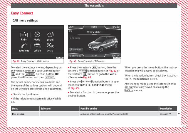
Fig. 42 Easy Connect: Main menu. Fig. 43 Easy Connect: CAR menu.
To select the settings menus, depending onthe version, press the Easy Connect button and the SETTINGS function button, OR
press the button and then SETTINGS .
The actual number of menus available andthe name of the various options will dependon the vehicle’s electronics and equipment.
● Switch the ignition on.
● If the Infotainment System is off, switch iton.
● Press the system's button, then thesystem's Vehicle function button ››› Fig. 42 orthe system’s button to go to the Vehi-cle menu ››› Fig. 43.
● Press the SETTINGS function button to openthe menu Vehicle settings menu››› Fig. 43.
● To select a function in the menu, press thedesired button.
When you press the menu button, the last se-lected menu will always be displayed.
When the function button check box is activa-ted , the function is active.
Any changes made using the settings menusare automatically saved on closing theBACK menus.
Menu Submenu Possible setting Description
ESC system – Activation of the Electronic Stability Programme (ESC) ››› page 177 »
33

The essentials
Menu Submenu Possible setting Description
TyresTyre pressure monitoring Tyre pressure storing (Calibration) ››› page 282
Winter tyres Activation and deactivation of the speed warning. Setting the speed warning value ››› page 284
Driver assistance
Front Assist system (frontmonitoring system) Activation/deactivation: Front Assist, advance warning, distance warning display ››› page 203
ACC (adaptive cruise control) Activation/deactivation: default distance level, driving profiles. ››› page 209
Fatigue detection Activation/deactivation ››› page 227
Parking and manoeu-vring ParkPilot Automatically activate, front volume, front sound settings, rear volume, rear sound set-
tings, adjust volume››› page 236
Vehicle lightsVehicle interior lighting Instrument and switch lighting, footrest lighting ››› page 142
Coming home/Leaving home func‐tion Start time for “Coming home” function, start time for “Leaving home” function ››› page 140
Windscreen wipers Windscreen wipers Automatic windscreen wipers, wipe when reversing ››› page 32
Opening and closingRadio-operated remote control Convenience open function ››› page 136
Central locking system Unlocking doors, automatic locking/unlocking, audible confirmation of switching offthe alarm
››› page 126
Multifunction display –
Current consumption, average consumption, volume to fill up, convenience consum-ers, ECOAdvice, travelling time, distance travelled, digital speed display, averagespeed, speeding warning, oil temperature, coolant temperature, restore data “fromstart”, restore data “total calculation”
››› page 35
Date and time –Time source, set the time, automatic summer time (DST) setting, select time zone,time format, set the date, date format
–
Measurement units – Distance, speed, temperature, volume, consumption –
Service – Chassis number, date of next SEAT service inspection, date of next oil change service ››› page 41
Factory settings –All settings can be reset: driver assistance, parking and manoeuvring, lights, rear viewmirrors, opening and closing, multi-function display
–
34
The essentials
››› in CAR menu on page 118
››› page 118
Driver information system
Introduction
With the ignition switched on, it is possibleto read the different functions of the displayby scrolling through the menus.
In vehicles with multifunction steering wheel,the multifunction display can only be operat-ed with the steering wheel buttons.
The number of menus displayed on the in-strument panel will vary according to the ve-hicle electronics and equipment.
A specialised workshop will be able to pro-gramme or modify additional functions, ac-cording to the vehicle equipment. SEAT rec-ommends visiting a SEAT Official Service.
Some menu options can only be read whenthe vehicle is at a standstill.
As long as a priority 1 warning is displayed, itwill not be possible to read the menus››› page 39. Some warning messages canbe confirmed and made to disappear with the
windscreen wiper lever button or the multi-function steering wheel button.
The information system also provides the fol-lowing information and displays (dependingon the vehicle's equipment):
Driving data ››› page 36■ MFD from departure■ MFD from refuelling■ MFD total calculation
Assist systems ››› page 38
Navigation ››› Booklet Navigation system
Audio ››› Booklet Radio or ››› Booklet Naviga-tion system
Telephone ››› Booklet Radio or ››› Book-let Navigation system
Vehicle status ››› page 33
WARNING
Any distraction may lead to an accident, withthe risk of injury.
● Do not operate the instrument panel con-trols when driving.
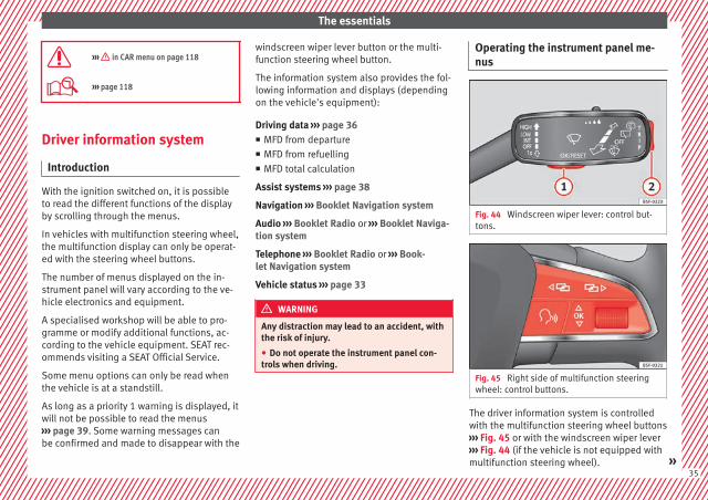
Operating the instrument panel me-nus
Fig. 44 Windscreen wiper lever: control but-tons.
Fig. 45 Right side of multifunction steeringwheel: control buttons.
The driver information system is controlledwith the multifunction steering wheel buttons››› Fig. 45 or with the windscreen wiper lever››› Fig. 44 (if the vehicle is not equipped withmultifunction steering wheel). »
35

The essentials
Enabling the main menu
● Switch the ignition on.
● If a message or vehicle pictogram appears,press button ››› Fig. 44 1 on the windscreenwiper lever or button on the multifunctionsteering wheel ››› Fig. 45.
● If managed from the windscreen wiper lev-er: to display the main screen ››› page 36 orto return to the main menu from anothermenu hold down the rocker button ››› Fig. 44
2 .
● If managed from the multifunction steeringwheel: the main menu list is not displayed.To go from point to point in the main menu,press button or several times››› Fig. 45.
Select a submenu
● Press the rocker switch ››› Fig. 44 2 on thewindscreen wiper lever up or down or turnthe thumbwheel of the multifunction steeringwheel ››› Fig. 45 until the desired option ap-pears marked on the menu.
● The selected option will be displayed with ahorizontal line underneath.
● To consult the submenu option, press but-ton ››› Fig. 44 1 on the windscreen wiperlever or button on the multifunction steer-ing wheel ››› Fig. 45.
Making changes according to the menu
● Make the desired changes with the rockerswitch on the windscreen wiper lever or thethumbwheel of the multifunction steeringwheel. To increase or decrease the valuesmore quickly, turn the thumbwheel faster.
● Mark or confirm the selection with button››› Fig. 44 1 on the windscreen wiper leveror button on the multifunction steeringwheel ››› Fig. 45.
Selection menu
Menu Function
Drivingdata
Information and possible configura-tions of the multifunction display(MFD) ››› page 36, ››› page 118.
Assistsystems
Information and possible configura-tions of the driver assistance systems››› page 38.
Navigation*
Information instructions from the acti-vated navigation system: when a routeguidance is activated, the turning ar-rows and proximity bars are displayed.The appearance is similar to the EasyConnect system.If route guidance is not activated, thedirection of travel (compass) and thename of the street along which you aredriving are shown ››› Booklet Naviga-tion system.
Menu Function
Audio
Station display on the radio.Track name on the CD.Track name in Media mode ››› Book-let Radio or ››› Booklet Navigation sys-tem.
TelephoneInformation and possible configura-tions of the mobile phone preinstalla-tion ››› Booklet Radio or ››› Book-let Navigation system.
Vehiclestatus
Display of the current warning or infor-mation texts and other system compo-nents, depending on the equipment››› page 118.
Journey data
The MFD (multifunction display) shows differ-ent values for the journey and the consump-tion.
Changing between display modes on theMFD
● In vehicles without multifunction steeringwheel: Press the rocker switch on thewindscreen wiper lever ››› Fig. 44.
● Vehicles with a multifunction steeringwheel: turn the thumbwheel ››› Fig. 45.
36
The essentials
Multifunction display memory
The multifunction display is equipped withthree memories that work automatically: MFDfrom departure, MFD from refuelling and MFDtotal calculation. On the screen display, youcan read which memory is currently dis-played.
Toggle between memories with the ignitionon and the memory displayed
Press the button on the windscreenwiper lever or the button of the multifunc-tion steering wheel.
Menu Function
MFD from de-parture
Display and storage of the values forthe journey and the consumptionfrom when the ignition is switchedon to when it is switched off.If the journey is continued in lessthan 2 hours after the ignition isswitched off, the new data is addedto the data already stored in thememory. The memory will automati-cally be deleted if the journey is in-terrupted for more than 2 hours.
MFD from re-fuelling
Display and storage of the values forthe journey and the consumption.By refuelling, the memory will beerased automatically.
Menu Function
MFD totalcalculation
The memory records the values for aspecific number of partial trips, upto a total of 19 hours and 59 mi-nutes or 99 hours and 59 minutes,or 1999.9 km or 9999 km, depend-ing on the model of instrument pan-el. On reaching either of these lim-itsa), the memory is automaticallyerased and starts to count from 0again.
a) It varies according to the instrument panel version.
Erasing a memory manually
● Select the memory that you wish to erase.
● Hold the button of the multifunctionsteering wheel or the button of the multi-function wheel pressed down for about 2 sec-onds.
Personalising the displays
In the Easy Connect system you can adjustwhich of the possible displays of the MFD canbe shown on the instrument panel displaywith the button and the SETTINGS functionbutton ››› page 118.
Data summary
Menu Function
Current fuelconsumption
The current fuel consumption dis-play operates throughout thejourney, in litres/100 km; andwith the engine running and thevehicle stopped, in litres/hour.
Average fuelconsumption
After turning on the ignition, aver-age fuel consumption in li-tres/100 km will be displayed af-ter travelling about 300 metres.Otherwise horizontal lines aredisplayed. The value shown is up-dated approximately every 5 sec-onds.
Operatingrange
Approximate distance in km thatcan still be travelled with the fuelremaining in the tank, assumingthe same style of driving is main-tained. This is calculated usingthe current fuel consumption.
Travellingtime
This indicates the hours (h) andminutes (min) since the ignitionwas switched on.
Distance cov-ered
Distance covered in km (m) afterswitching on the ignition.
Average speed
The average speed will be shownafter a distance of about 100 me-tres has been travelled. Otherwisehorizontal lines are displayed.The value shown is updated ap-proximately every 5 seconds. »
37

The essentials
Menu Function
Digital dis-play of speed
Current speed displayed in digitalformat.
Speed warningat --- km/h orSpeed warningat --- mph
If the stored speed is exceeded(between 30 - 250 km/h, or 19 -155 mph), an audible warning isgiven together with a visual warn-ing.
Oil tempera-ture
Updated engine oil temperaturedigital display
Coolant tem-perature gauge
Digital display of the current tem-perature of the liquid coolant.
Storing a speed with the speed warning
● Select the display Speed warning at--- km/h (--- mph)● Press the button on the windscreenwiper lever or the button on the multifunc-tion steering wheel to store the current speedand activate the warning.
● To switch system on: adjust to the desiredspeed within 5 seconds using the rockerswitch on the windscreen wiper lever orby turning the thumbwheel on the multifunc-tion steering wheel. Next, press the button or again or wait several seconds.
The speed is stored and the warning activa-ted.
● To switch system off: press the but-ton or . The stored speed is de-leted.
Assist systems menu
Menu Function
ACC Display of Adaptive Cruise Control(ACC) ››› page 209.
Front Assist Switching the monitoring systemon and off ››› page 203.
Fatigue detec-tion*
Switching the fatigue detectionon or off (pause recommenda-tion) ››› page 227.
Status display
Bonnet, rear lid and doors open
Fig. 46 A: bonnet open; B: rear lid open; C:front left door open; D: rear right door open(5-door vehicles only).
When the ignition is switched on or whendriving, the bonnet, rear lid or doors that areopen will be indicated on the instrument pan-el display, and, as applicable, this will be in-dicated audibly. The display may vary accord-ing to the type of instrument panel fitted.
38
The essentials
Illustra-tion
Key to ››› Fig. 46
A Do not continue driving!The bonnet is open or is not properlyclosed ››› page 267.
B Do not continue driving!The rear lid is open or is not properlyclosed ››› page 16.
C, D Do not continue driving!A vehicle door is open or is not properlyclosed ››› page 126.
››› page 114
Warning and information messages
The system runs a check on certain compo-nents and functions when the ignition isswitched on and while the vehicle is moving.Faults in the operation are displayed on thescreen using red and yellow symbols andmessages on the instrument panel display(››› page 117, ››› page 44) and, insome cases, with audible warnings. The dis-play may vary according to the type of instru-ment panel fitted.
Priority 1 warning (red symbols)
Symbol flashing or lit; partly combined with audiblewarnings. Stop the vehicle! It is dangerous ››› in Warningsymbols on page 117!Check the function that is faulty and repair it. If necessa-ry, request assistance from specialised personnel.
Priority 2 warning (yellow symbols)
Symbol flashing or lit; partly combined with audiblewarnings.A faulty function, or fluids which are below the correctlevels may cause damage to the vehicle! ››› in Warn-ing symbols on page 118Check the faulty function as soon as possible. If neces-sary, request assistance from specialised personnel.
Informative text
Information relating to different vehicle processes.
››› page 117
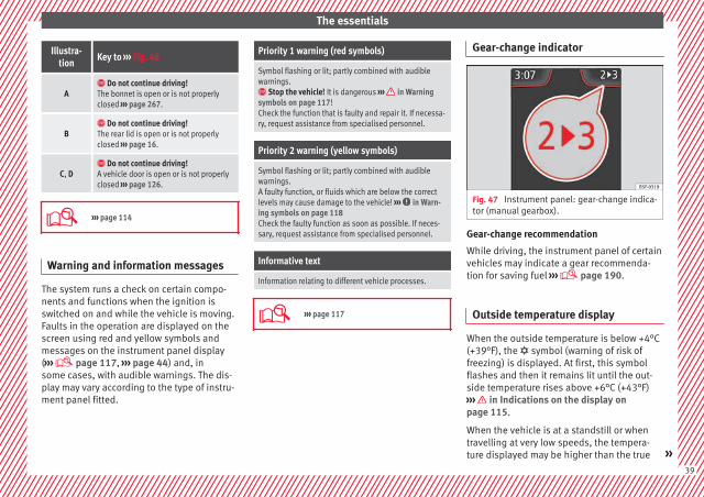
Gear-change indicator
Fig. 47 Instrument panel: gear-change indica-tor (manual gearbox).
Gear-change recommendation
While driving, the instrument panel of certainvehicles may indicate a gear recommenda-tion for saving fuel ››› page 190.
Outside temperature display
When the outside temperature is below +4°C(+39°F), the symbol (warning of risk offreezing) is displayed. At first, this symbolflashes and then it remains lit until the out-side temperature rises above +6°C (+43°F)››› in Indications on the display onpage 115.
When the vehicle is at a standstill or whentravelling at very low speeds, the tempera-ture displayed may be higher than the true »
39
The essentials
outside temperature as a result of the heatproduced by the engine.
The temperatures measured range from-40°C to +50°C (-40°F to +122°F).
Engine oil temperature display
The engine reaches its operating temperaturewhen in normal driving conditions the oiltemperature is between 80°C (178°F) and120°C (248°F). If the engine is required towork hard and the outside temperature ishigh, the engine oil temperature can in-crease. This does not present any problem aslong as the warning lamps ››› table onpage 46 or ››› table on page 46 do notappear on the display.
Vehicles without multifunction steeringwheel
● Press the rocker switch ››› Fig. 44 2 untilthe main menu appears. Enter into Drivingdata. With the button 2 move to the oiltemperature gauge.
Vehicles with multifunction steering wheel
● Enter the submenu Driving data andturn the thumbwheel until the oil tempera-ture display appears.
Additional electrical appliances
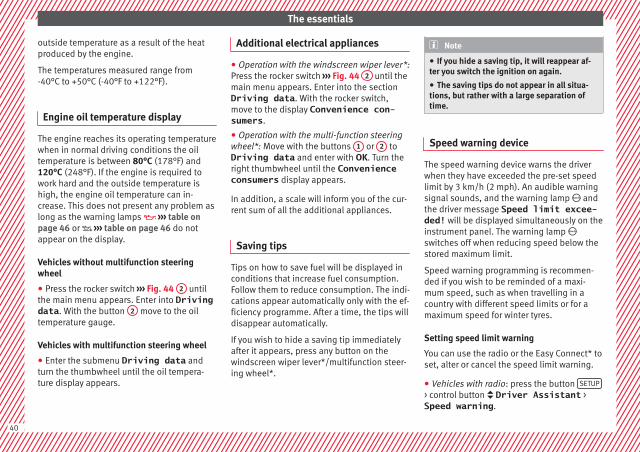
● Operation with the windscreen wiper lever*:Press the rocker switch ››› Fig. 44 2 until themain menu appears. Enter into the sectionDriving data. With the rocker switch,move to the display Convenience con-sumers.
● Operation with the multi-function steeringwheel*: Move with the buttons 1 or 2 toDriving data and enter with OK. Turn theright thumbwheel until the Convenienceconsumers display appears.
In addition, a scale will inform you of the cur-rent sum of all the additional appliances.
Saving tips
Tips on how to save fuel will be displayed inconditions that increase fuel consumption.Follow them to reduce consumption. The indi-cations appear automatically only with the ef-ficiency programme. After a time, the tips willdisappear automatically.
If you wish to hide a saving tip immediatelyafter it appears, press any button on thewindscreen wiper lever*/multifunction steer-ing wheel*.
Note
● If you hide a saving tip, it will reappear af-ter you switch the ignition on again.
● The saving tips do not appear in all situa-tions, but rather with a large separation oftime.
Speed warning device
The speed warning device warns the driverwhen they have exceeded the pre-set speedlimit by 3 km/h (2 mph). An audible warningsignal sounds, and the warning lamp andthe driver message Speed limit excee-ded! will be displayed simultaneously on theinstrument panel. The warning lamp switches off when reducing speed below thestored maximum limit.
Speed warning programming is recommen-ded if you wish to be reminded of a maxi-mum speed, such as when travelling in acountry with different speed limits or for amaximum speed for winter tyres.
Setting speed limit warning
You can use the radio or the Easy Connect* toset, alter or cancel the speed limit warning.
● Vehicles with radio: press the button SETUP
> control button Driver Assistant >Speed warning.
40
The essentials
● Vehicles with Easy Connect: press the but-ton Systems or else Vehicle systems >Driver assistant > Speed warning.
The warning limit can be set from 30 to240 km/h (20 to 149 mph). The adjustmentis made at 10 km/h (5 mph) intervals.
Note
● Please bear in mind that, even with thespeed warning function, it is still importantto keep an eye on the vehicle speed with thespeedometer and to observe the legal speedlimits.
● The speed limit warning function in the ver-sion for some countries warns you at a speedof 120 km/h (75 mph). This is a factory-setspeed limit.
Service intervals
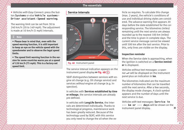
Fig. 48 Instrument panel
The service interval indication appears on theinstrument panel display ››› Fig. 48 1 .
SEAT distinguishes between services with en-gine oil change (e.g. Oil change service) andservices without engine oil change (e.g. In-spection).
In vehicles with Services established by timeor mileage, the service intervals are alreadypre-defined.
In vehicles with LongLife Service, the inter-vals are determined individually. Thanks totechnological progress, maintenance workhas been greatly reduced. Because of thetechnology used by SEAT, with this serviceyou only need to change the oil when the ve-
hicle so requires. To calculate this change(max. 2 years), the vehicle's conditions ofuse and individual driving styles are consid-ered. The advance warning first appears 20days before the date established for the cor-responding service. The kilometres (miles)remaining until the next service are alwaysrounded up to the nearest 100 km (miles)and the time is given in complete days. Thecurrent service message cannot be vieweduntil 500 km after the last service. Prior tothis, only lines are visible on the display.
Inspection reminder
When the Service date is approaching, whenthe ignition is switched on a Service remind-er is displayed.
Vehicles without text messages: a span-ner will be displayed on the instrumentpanel plus an indication in km.
The kilometres indicated are the maximumnumber of kilometres that can be travelleduntil the next service. After a few seconds,the display mode changes. A clock symbolappears and the number of days until thenext service is due.
Vehicles with text messages: Service in--- km or --- days will be shown on theinstrument panel display. »
41

The essentials
Service due
When the service date is due, an audiblewarning is given when the ignition is switch-ed on and the spanner displayed on thescreen flashes for a few seconds .
Vehicles with text messages: Service nowwill be shown on the instrument panel dis-play.
Reading a service notification
With the ignition switched on, the engine offand the vehicle at a standstill, the currentservice notification can be read:
Press and hold the button 2 for more than 5seconds to consult the service message.
When the service date has passed, a minussign is displayed in front of the number of kil-ometres or days.
Vehicles with text messages: the followingmessage is displayed: Service --- km(miles) or --- days ago.
The time can also be set via the buttonand the SETTINGS function button in the EasyConnect system ››› page 33.
Resetting service interval display
If the service was not carried out by a SEATdealership, the display can be reset as fol-lows:
● Switch off the ignition, press and hold but-ton 2 .
● Switch ignition back on.
● Release the 2 button and press it againfor the next 20 seconds.
Note
● The service message disappears after a fewseconds, when the engine is started or whenOK/RESET is pressed on the windscreen wiper
lever, or OK on the multifunction steeringwheel.
● In vehicles with the LongLife system inwhich the battery has been disconnected fora long period of time, it is not possible to cal-culate the date of the next service. Thereforethe service interval display may not be cor-rect. In this case, bear in mind the maximumservice intervals permitted in the ››› Book-let Maintenance Programme.
● If you reset the display manually, the nextservice interval will be indicated as in vehi-cles with fixed service intervals. For this rea-son we recommend that the service intervaldisplay be reset by a SEAT authorised Dealer.
Cruise control
Related video
Fig. 49 Dash panel
42

The essentials
Operating the cruise control system (CCS)*
Fig. 50 On the left of the steering column:controller and buttons to operate the cruisecontrol system.
Fig. 51 On the left of the steering column:third lever for operating the cruise control sys-tem.
FunctionPosition of the turn signal lever ››› Fig. 50or the third lever ››› Fig. 51
Effect
Switching on the cruise control sys-tem
Move controller 1 to the position on the turn signal lever or move the third leverforward.
The system switches on. The last set speed of thecruise control is stored. It does not take effect yet.
Switching on the cruise control sys-tem
Press button 3 on the turn signal lever or button 1 on the third lever.The current speed is stored and the cruise control isactivated.
Temporarily switching off the cruisecontrol
Move controller 1 of the turn signal lever to the position or move the thirdlever into pressure point .
The limiter is switched off temporarily. The speed willbe stored.
Switching on the cruise control sys-tem again
Press button 3 on the turn signal lever or move the third lever into pressure point.
The set speed control is activated. »
43

The essentials
FunctionPosition of the turn signal lever ››› Fig. 50or the third lever ››› Fig. 51
Effect
Increasing the set speed of the cruisecontrol
Briefly press button 3 on the turn signal lever in the area or press 1 onthe third lever to increase the speed in small increments of 1 km/h (1 mph) and setit.
The speed is changed to the set value.Press on the third lever to increase the speed in increments of 10 km/h(5 mph) and set it.
Hold down button 3 on the turn signal lever in the area or hold down toincrease continuously in increments of 10 km/h (5 mph) and set it.
Reducing the set speed of the cruisecontrol
Briefly press button 3 on the turn signal lever in the area or move the thirdlever into position to reduce the speed in small increments of 1 km/h (1 mph)and set it.
The speed is changed to the set value.Press on the third lever to reduce the speed in increments of 10 km/h (5 mph)and set it.
Hold down button 3 on the turn signal lever in the area or hold down tocontinuously decrease the speed in increments of 10 km/h (5 mph), then set it.
Switching off the cruise control sys-tem
Move controller 1 of the turn signal lever into position or the third lever into po-sition .
The system switches off. The set speed will be stored.
››› in Operation on page 199
››› page 198
Warning lamps
Related video
Fig. 52 Dash panel
44
The essentials
On the instrument panel
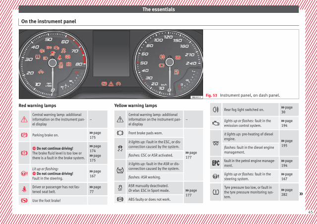
Fig. 53 Instrument panel, on dash panel.
Red warning lamps
Central warning lamp: additionalinformation on the instrument pan-el display
–
Parking brake on.››› page 175
Do not continue driving!The brake fluid level is too low orthere is a fault in the brake system.
››› page 174››› page 175
Lit up or flashing: Do not continue driving!Fault in the steering.
››› page 167
Driver or passenger has not fas-tened seat belt.
››› page 77
Use the foot brake!
Yellow warning lamps
Central warning lamp: additionalinformation on the instrument pan-el display
–
Front brake pads worn.
››› page 177
it lights up: Fault in the ESC, or dis-connection caused by the system.
flashes: ESC or ASR activated.
it lights up: fault in the ASR or dis-connection caused by the system.
flashes: ASR working.
ASR manually deactivated.Or else: ESC in Sport mode. ››› page
177 ABS faulty or does not work.
Rear fog light switched on.››› page 30
lights up or flashes: fault in theemission control system.
››› page 194
it lights up: pre-heating of dieselengine. ››› page
195flashes: fault in the diesel enginemanagement.
fault in the petrol engine manage-ment.
››› page 194
lights up or flashes: fault in thesteering system.
››› page 167
Tyre pressure too low, or fault inthe tyre pressure monitoring sys-tem.
››› page 282 »
45
The essentials
Fuel tank almost empty.››› page 117
Fault in airbag system and seatbelt tensioners.
››› page 82
Other warning lamps
Left or right turn signal.
››› page 31
Hazard warning lights on.››› page 141
Trailer turn signals››› page 245
it lights up green: Press the brakepedal!It blinks in green: the selector leverlocking button has not engaged.
››› page 183
it lights up green: cruise control ac-tivated or speed limiter switchedon and active.
››› page 42››› page 200
it blinks in green: the speed set bythe speed limiter has been excee-ded.
Main beam on or flasher on.››› page 31
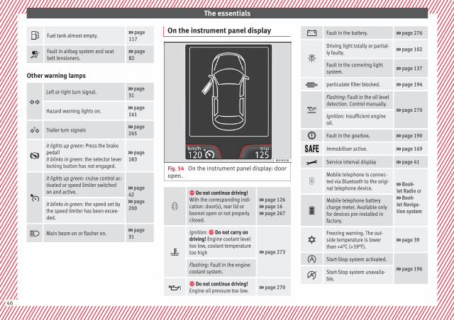
On the instrument panel display
Fig. 54 On the instrument panel display: dooropen.
Do not continue driving!With the corresponding indi-cation: door(s), rear lid orbonnet open or not properlyclosed.
››› page 126››› page 16››› page 267
Ignition: Do not carry ondriving! Engine coolant leveltoo low, coolant temperaturetoo high ››› page 273
Flashing: Fault in the enginecoolant system.
Do not continue driving!Engine oil pressure too low.
››› page 270
Fault in the battery. ››› page 276
Driving light totally or partial-ly faulty.
››› page 102
Fault in the cornering lightsystem.
››› page 137
particulate filter blocked. ››› page 194
Flashing: Fault in the oil leveldetection. Control manually.
››› page 270Ignition: Insufficient engineoil.
Fault in the gearbox. ››› page 190
Immobiliser active. ››› page 169
Service interval display ››› page 41
Mobile telephone is connec-ted via Bluetooth to the origi-nal telephone device.
››› Book-let Radio or››› Book-let Naviga-tion system
Mobile telephone batterycharge meter. Available onlyfor devices pre-installed infactory.
Freezing warning. The out-side temperature is lowerthan +4°C (+39°F).
››› page 39
Start-Stop system activated.
››› page 196
Start-Stop system unavaila-ble.
46
The essentials
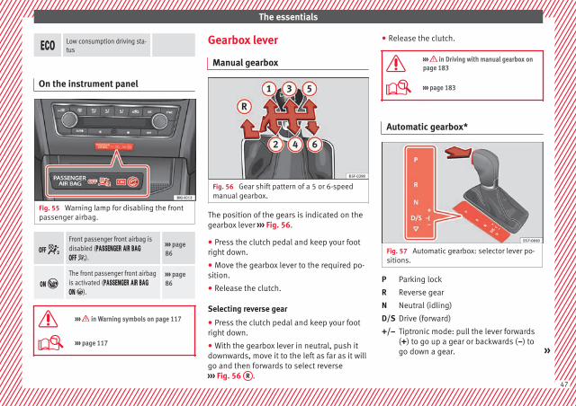
Low consumption driving sta-tus
On the instrument panel
Fig. 55 Warning lamp for disabling the frontpassenger airbag.
Front passenger front airbag isdisabled ( ).
››› page 86
The front passenger front airbagis activated ( ).
››› page 86
››› in Warning symbols on page 117
››› page 117
Gearbox lever
Manual gearbox
Fig. 56 Gear shift pattern of a 5 or 6-speedmanual gearbox.
The position of the gears is indicated on thegearbox lever ››› Fig. 56.
● Press the clutch pedal and keep your footright down.
● Move the gearbox lever to the required po-sition.
● Release the clutch.
Selecting reverse gear
● Press the clutch pedal and keep your footright down.
● With the gearbox lever in neutral, push itdownwards, move it to the left as far as it willgo and then forwards to select reverse››› Fig. 56 R .
● Release the clutch.
››› in Driving with manual gearbox onpage 183
››› page 183
Automatic gearbox*
Fig. 57 Automatic gearbox: selector lever po-sitions.
Parking lock
Reverse gear
Neutral (idling)
Drive (forward)
Tiptronic mode: pull the lever forwards(+) to go up a gear or backwards (–) togo down a gear. »
P
R
N
D/S
+/–
47

The essentials
››› in Selector lever positions onpage 184
››› page 183
››› page 48
Manual release of the selector lever
Fig. 58 Selector lever: manual release fromposition P.
Should the power supply be interrupted,there is a manual unlocking device located
under the console of the selector lever, onthe right. Releasing the selector lever re-quires a certain degree of practical skill.
● Unlocking: use the flat part of a screwdriverblade.
Removing the cover from the selector lever
● Apply the handbrake ››› to ensure thatthe car does not move.
● Carefully pull the corners of the selectorlever boot and twist it upwards above the lev-er handle.
Releasing the selector lever
● Using a screwdriver, press and hold the yel-low unlocking tab sideways ››› Fig. 58.
● Press the interlock button on the selectorlever and move the selector lever to posi-tion N.
● After carrying out the manual release, at-tach the selector lever boot on the gearboxconsole again.
If the power supply should ever fail (e.g. dis-charged battery) and the vehicle has to be
pushed or towed, the selector lever must firstbe moved to position N, after operating themanual release mechanism.
WARNING
The selector lever may be moved out of posi-tion P only when the handbrake is firmly ap-plied. If this does not work, secure the vehi-cle with the brake pedal. On a slope the vehi-cle could otherwise start to move inadver-tently after shifting the selector lever out ofposition P - accident risk!
Air conditioning
Related video
Fig. 59 Air conditioning
48

The essentials
How does Climatronic* work?
Fig. 60 In the centre console: Climatronic con-trols
To switch a specific function on, press the ap-propriate button. Press the button again toswitch off the function.
The LED on each control lights up to indicatethat the respective function of a control hasbeen switched on.
1
TemperatureThe left and right sides can be adjusted separately: turn the control to adjust the temperature.
2
FanThe power of the fan is automatically adjusted. Press the buttons to manually adjust the fan.
3
Air distributionThe airflow adjusts automatically for comfort. You can also switch it on manually using the buttons 3 .
4 Indications on the display screen of the fan speed and the temperature selected for the right and left sides.
Defrost function
The air drawn in from outside the vehicle is directed at the windscreen and air recirculation is automatically switched off. To defrost the wind-screen more quickly, the air is dehumidified at temperatures over approximately +3°C (+38°F) and the fan runs at maximum output.
The air is directed at the chest of driver and passengers by the dash panel air vents. »49
The essentials
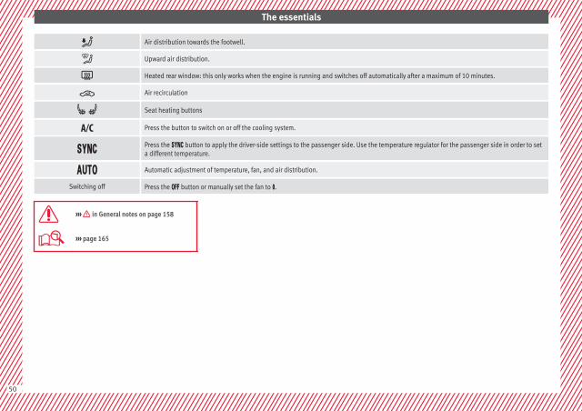
Air distribution towards the footwell.
Upward air distribution.
Heated rear window: this only works when the engine is running and switches off automatically after a maximum of 10 minutes.
Air recirculation
Seat heating buttons
Press the button to switch on or off the cooling system.
Press the button to apply the driver-side settings to the passenger side. Use the temperature regulator for the passenger side in order to seta different temperature.
Automatic adjustment of temperature, fan, and air distribution.
Switching off Press the button or manually set the fan to .
››› in General notes on page 158
››› page 165
50
The essentials
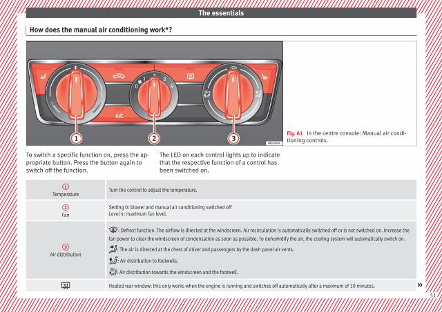
How does the manual air conditioning work*?
Fig. 61 In the centre console: Manual air condi-tioning controls.
To switch a specific function on, press the ap-propriate button. Press the button again toswitch off the function.
The LED on each control lights up to indicatethat the respective function of a control hasbeen switched on.
1
TemperatureTurn the control to adjust the temperature.
2
FanSetting 0: blower and manual air conditioning switched offLevel 4: maximum fan level.
3
Air distribution
: Defrost function. The airflow is directed at the windscreen. Air recirculation is automatically switched off or is not switched on. Increase the
fan power to clear the windscreen of condensation as soon as possible. To dehumidify the air, the cooling system will automatically switch on.
: The air is directed at the chest of driver and passengers by the dash panel air vents.
: Air distribution to footwells.
: Air distribution towards the windscreen and the footwell.
Heated rear window: this only works when the engine is running and switches off automatically after a maximum of 10 minutes. »51
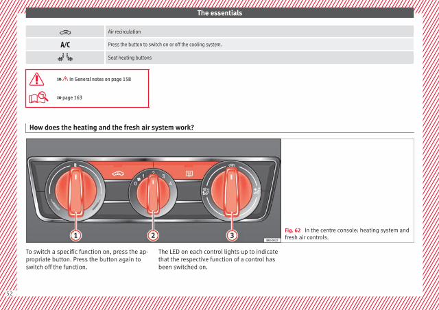
The essentials
Air recirculation
Press the button to switch on or off the cooling system.
Seat heating buttons
››› in General notes on page 158
››› page 163
How does the heating and the fresh air system work?
Fig. 62 In the centre console: heating system andfresh air controls.
To switch a specific function on, press the ap-propriate button. Press the button again toswitch off the function.
The LED on each control lights up to indicatethat the respective function of a control hasbeen switched on.
52

The essentials
1
TemperatureTurn the control to adjust the temperature. The temperature cannot be lower than that of the exterior air temperature, as this system cannot coolor dehumidify the air.
2
FanSetting 0: blower and manual air conditioning switched offLevel 4: maximum fan level.
3
Air distribution
: Defrost function. The airflow is directed at the windscreen.
: The air is directed at the chest of driver and passengers by the dash panel air vents.
: Air distribution to footwells.
: Air distribution towards the windscreen and the footwell.
Heated rear window: this only works when the engine is running and switches off automatically after a maximum of 10 minutes.
Air recirculation
››› in General notes on page 158
››› page 161
53
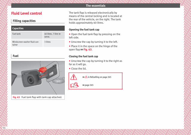
The essentials
Fluid Level control
Filling capacities
Capacities
Fuel tank 40 litres. 7 litre re-serve.
Windscreen washer fluid con-tainer
3 litres
Fuel
Fig. 63 Fuel tank flap with tank cap attached.
The tank flap is released electronically bymeans of the central locking and is located atthe rear of the vehicle, on the right. The tankholds approximately 40 litres.
Opening the fuel tank cap
● Open the fuel tank flap by pressing on theleft side.
● Unscrew the cap by turning it to the left.
● Place it in the space on the hinge of theopen flap ››› Fig. 63.
Closing the fuel tank cap
● Unscrew the cap by turning it to the right asfar as it will go.
● Close the lid.
››› in Refuelling on page 265
››› page 265
54

The essentials
Oil
Fig. 64 Engine oil dipstick. Fig. 65 In the engine compartment: Engineoil filler cap.
The level is measured using the dipstick loca-ted in the engine compartment››› page 270.
The oil should leave a mark between zonesA and C . It should never exceed zone A .
● Zone A : Do not add oil.
● Zone B : You can add oil but keep the levelin that zone.
● Zone C : Add oil up to zone B .
Topping up engine oil
● Unscrew cap from oil filler opening.
● Add oil slowly.
● At the same time, check the level to ensureyou do not add too much.
● When the oil level reaches at least zone B ,unscrew the engine oil filler cap carefully.
Engine oil additives
No type of additive should be mixed with theengine oil. The deterioration caused by theseadditives is not covered by the warranty. »
55

The essentials
Engine oil specifications
Engine type Flexible service (LongLife)Set Service (dependent on time/distance travel-
led)
Petrol enginesVW 508 00
VW 504 00a)VW 504 00
VW 502 00b)
Engines with Particulate filter (DPF)c) VW 507 00 VW 507 00
a) Use of engine oil compliant with the VW 504 00 specification instead of VW 508 00 may have a slight negative effect on the vehicle’s exhaust gas values.b) If the quality of the fuel available in the country does not fulfil the EN 228 (for petrol) and EN 590 (for diesel) standards.c) Only use recommended oils, otherwise you may damage the engine.
››› in Changing engine oil on page 273
››› page 270
Coolant
Fig. 66 Engine compartment: coolant expan-sion tank cap.
The coolant tank is located in the enginecompartment ››› page 270.
When the engine is cold, replace the coolantwhen the level is below .
Coolant specifications
The engine cooling system is supplied fromthe factory with a specially treated mixture ofwater and at least 40 % of the additive G13(TL-VW 774 J), purple. This mixture gives thenecessary frost protection down to -25°C(-13°F) and protects the light alloy parts ofthe engine cooling system against corrosion.It also prevents scaling and considerably rai-ses the boiling point of the coolant.
To protect the cooling system, the percentageof additive must always be at least 40 %,even in warm climates where anti-freeze pro-tection is not required.
If for weather reasons further protection isnecessary, the proportion of additive may beincreased, but only up to 60 %; otherwise an-tifreeze protection will diminish and this willworsen cooling.
When the coolant is topped up, use a mixtureof distilled water and at least 40 % of theG13 or G12 plus-plus (TL-VW 774 G) additive(both are purple) to obtain an optimum anti-corrosion protection ››› in Topping up cool-ant on page 275. The mixture of G13 withG12 plus (TL-VW 774 F), G12 (red) or G11(green-blue) engine coolants will significant-ly reduce anti-corrosion protection andshould therefore be avoided ››› in Toppingup coolant on page 275.
››› in Topping up coolant on page 274
››› page 273
56
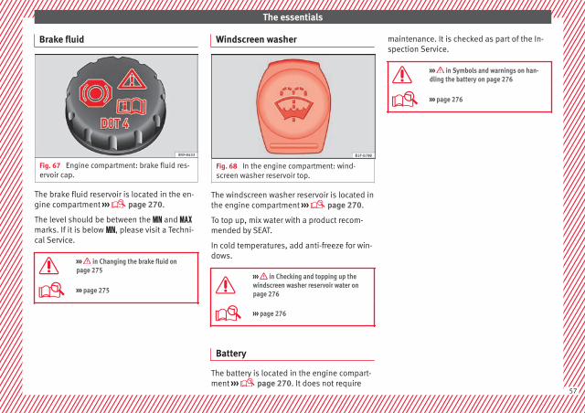
The essentials
Brake fluid
Fig. 67 Engine compartment: brake fluid res-ervoir cap.
The brake fluid reservoir is located in the en-gine compartment ››› page 270.
The level should be between the and marks. If it is below , please visit a Techni-cal Service.
››› in Changing the brake fluid onpage 275
››› page 275
Windscreen washer
Fig. 68 In the engine compartment: wind-screen washer reservoir top.
The windscreen washer reservoir is located inthe engine compartment ››› page 270.
To top up, mix water with a product recom-mended by SEAT.
In cold temperatures, add anti-freeze for win-dows.
››› in Checking and topping up thewindscreen washer reservoir water onpage 276
››› page 276
Battery
The battery is located in the engine compart-ment ››› page 270. It does not require
maintenance. It is checked as part of the In-spection Service.
››› in Symbols and warnings on han-dling the battery on page 276
››› page 276
57

The essentials
Emergencies
Fuses
Fuse location
Fig. 69 On the driver-side dash panel: fusebox cover.
Fig. 70 In the engine compartment: fuse boxcover.
Opening and closing the fuse box situatedbelow the dash panel
● Opening: remove the fuse box cover in thedirection indicated ››› Fig. 69.
● Closing: click the cover back into place.
To open the engine compartment fuse box
● Raise the bonnet.
● Press the locking tabs to release the fusebox cover ››› Fig. 70
● Then lift the cover out.
● To fit the cover, place it on the fuse box.Push the locking tabs down until they clickaudibly into place.
Identifying fuses situated below the dashpanel by colours
Colour Amp rating
Black 1
Purple 3
Light brown 5
Brown 7.5
Red 10
Blue 15
Yellow 20
White or transparent 25
Colour Amp rating
Green 30
Orange 40
››› in Introduction on page 100
››› page 100
Replacing a blown fuse
Fig. 71 Image of a blown fuse.
Preparation
● Switch off the ignition, lights and all elec-trical equipment.
● Open the corresponding fuse box››› page 100.
58
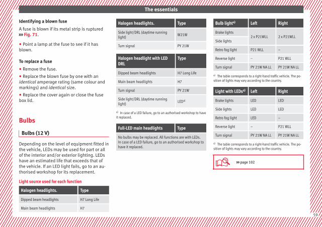
The essentials
Identifying a blown fuse
A fuse is blown if its metal strip is ruptured››› Fig. 71.
● Point a lamp at the fuse to see if it hasblown.
To replace a fuse
● Remove the fuse.
● Replace the blown fuse by one with anidentical amperage rating (same colour andmarkings) and identical size.
● Replace the cover again or close the fusebox lid.
Bulbs
Bulbs (12 V)
Depending on the level of equipment fitted inthe vehicle, LEDs may be used for part or allof the interior and/or exterior lighting. LEDshave an estimated life that exceeds that ofthe vehicle. If an LED light fails, go to an au-thorised workshop for its replacement.
Light source used for each function
Halogen headlights. Type
Dipped beam headlights H7 Long Life
Main beam headlights H7
Halogen headlights. Type
Side light/DRL (daytime runninglight)
W21W
Turn signal PY 21W
Halogen headlight with LEDDRL
Type
Dipped beam headlights H7 Long Life
Main beam headlights H7
Turn signal PY 21W
Side light/DRL (daytime runninglight)
LEDa)
a) In case of a LED failure, go to an authorised workshop to haveit replaced.
Full-LED main headlights Type
No bulbs may be replaced. All functions are with LEDs.In case of a LED failure, go to an authorised workshop tohave it replaced.
Bulb lighta) Left Right
Brake lights2 x P21WLL 2 x P21WLL
Side lights
Retro fog light P21 WLL –
Reverse light – P21 WLL
Turn signal PY 21W NA LL PY 21W NA LL
a) The table corresponds to a right-hand traffic vehicle. The po-sition of lights may vary according to the country.
Light with LEDsa) Left Right
Brake lights LED LED
Side lights LED LED
Retro fog light LED –
Reverse light – P21 WLL
Turn signal PY 21W NA LL PY 21W NA LL
a) The table corresponds to a right-hand traffic vehicle. The po-sition of lights may vary according to the country.
››› page 102
59
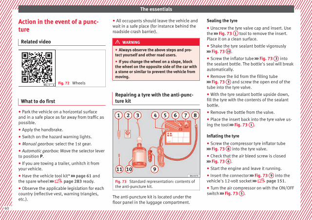
The essentials
Action in the event of a punc-ture
Related video
Fig. 72 Wheels
What to do first
● Park the vehicle on a horizontal surfaceand in a safe place as far away from traffic aspossible.
● Apply the handbrake.
● Switch on the hazard warning lights.
● Manual gearbox: select the 1st gear.
● Automatic gearbox: Move the selector leverto position P.
● If you are towing a trailer, unhitch it fromyour vehicle.
● Have the vehicle tool kit* ››› page 61 andthe spare wheel ››› page 283 ready.
● Observe the applicable legislation for eachcountry (reflective vest, warning triangles,etc.).
● All occupants should leave the vehicle andwait in a safe place (for instance behind theroadside crash barrier).
WARNING
● Always observe the above steps and pro-tect yourself and other road users.
● If you change the wheel on a slope, blockthe wheel on the opposite side of the car witha stone or similar to prevent the vehicle frommoving.
Repairing a tyre with the anti-punc-ture kit
Fig. 73 Standard representation: contents ofthe anti-puncture kit.
The anti-puncture kit is located under thefloor panel in the luggage compartment.
Sealing the tyre
● Unscrew the tyre valve cap and insert. Usethe ››› Fig. 73 1 tool to remove the insert.Place it on a clean surface.
● Shake the tyre sealant bottle vigorously››› Fig. 73 10 .
● Screw the inflator tube ››› Fig. 73 3 intothe sealant bottle. The bottle's seal will breakautomatically.
● Remove the lid from the filling tube››› Fig. 73 3 and screw the open end of thetube into the tyre valve.
● With the tyre sealant bottle upside down,fill the tyre with the contents of the sealantbottle.
● Remove the bottle from the valve.
● Place the insert back into the tyre valve us-ing the tool ››› Fig. 73 1 .
Inflating the tyre
● Screw the compressor tyre inflator tube››› Fig. 73 8 into the tyre valve.
● Check that the air bleed screw is closed››› Fig. 73 6 .
● Start the engine and leave it running.
● Insert the connector ››› Fig. 73 9 into thevehicle's 12-volt socket ››› page 151.
● Turn the air compressor on with the ON/OFFswitch ››› Fig. 73 5 .
60

The essentials
● Keep the air compressor running until itreaches 2.0 to 2.5 bar(29-36 psi/200-250 kPa). A maximum of 8minutes.
● Disconnect the air compressor.
● If it does not reach the pressure indicated,unscrew the tyre inflator tube from the valve.
● Move the vehicle 10m so that the sealant isdistributed throughout the tyre.
● Screw the compressor tyre inflator into thevalve.
● Repeat the inflation process.
● If the indicated pressure still cannot bereached, the tyre is too badly damaged. Stopand request assistance from an authorisedtechnician.
● Disconnect the air compressor. Unscrewthe tyre inflator tube from the tyre valve.
● When the tyre pressure is between 2.5 and2.0 bars, continue driving without exceeding80 km/h (50 mph).
● Check the pressure again after 10 minutes››› page 95.
››› in TMS (Tyre Mobility System)* onpage 94
››› page 94
Changing a wheel
Related video
Fig. 74 Wheels
Vehicle tool kit
Fig. 75 Underneath the floor panel of the lug-gage compartment: vehicle tool kit.
An adapter for the anti-theft wheel bolts*
Towline anchorage
Box spanner for wheel bolts*
Crank handle for jack
1
2
3
4
Jack*
Hook for extracting the central wheeltrims*
Clip for removing the wheel bolt caps.
››› in Vehicle tools on page 93
››› page 93
Central trim for steel rims*
Fig. 76 Correct positioning of the centralwheel trim for steel rims.
The central trims must be removed for accessto the wheel bolts. »
5
6
7
61
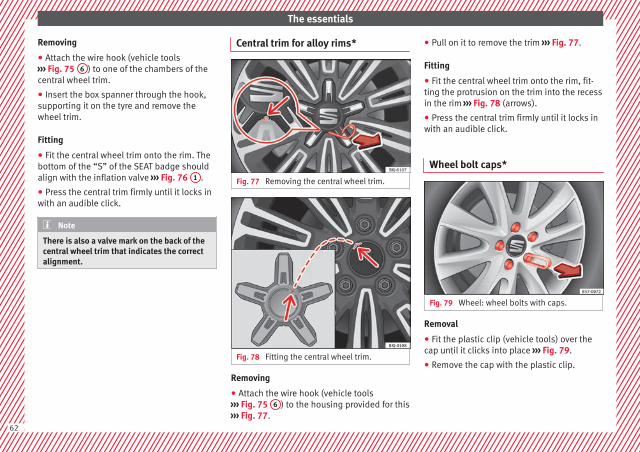
The essentials
Removing
● Attach the wire hook (vehicle tools››› Fig. 75 6 ) to one of the chambers of thecentral wheel trim.
● Insert the box spanner through the hook,supporting it on the tyre and remove thewheel trim.
Fitting
● Fit the central wheel trim onto the rim. Thebottom of the “S” of the SEAT badge shouldalign with the inflation valve ››› Fig. 76 1 .
● Press the central trim firmly until it locks inwith an audible click.
Note
There is also a valve mark on the back of thecentral wheel trim that indicates the correctalignment.
Central trim for alloy rims*
Fig. 77 Removing the central wheel trim.
Fig. 78 Fitting the central wheel trim.
Removing
● Attach the wire hook (vehicle tools››› Fig. 75 6 ) to the housing provided for this››› Fig. 77.
● Pull on it to remove the trim ››› Fig. 77.
Fitting
● Fit the central wheel trim onto the rim, fit-ting the protrusion on the trim into the recessin the rim ››› Fig. 78 (arrows).
● Press the central trim firmly until it locks inwith an audible click.
Wheel bolt caps*
Fig. 79 Wheel: wheel bolts with caps.
Removal
● Fit the plastic clip (vehicle tools) over thecap until it clicks into place ››› Fig. 79.
● Remove the cap with the plastic clip.
62
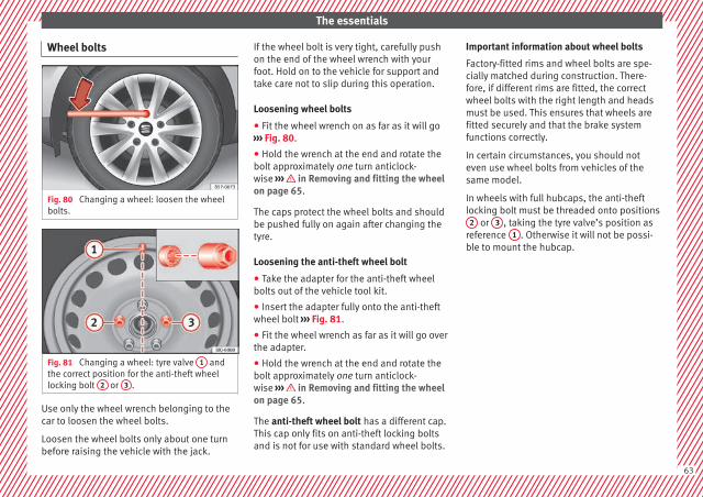
The essentials
Wheel bolts
Fig. 80 Changing a wheel: loosen the wheelbolts.
Fig. 81 Changing a wheel: tyre valve 1 andthe correct position for the anti-theft wheellocking bolt 2 or 3 .
Use only the wheel wrench belonging to thecar to loosen the wheel bolts.
Loosen the wheel bolts only about one turnbefore raising the vehicle with the jack.
If the wheel bolt is very tight, carefully pushon the end of the wheel wrench with yourfoot. Hold on to the vehicle for support andtake care not to slip during this operation.
Loosening wheel bolts
● Fit the wheel wrench on as far as it will go››› Fig. 80.
● Hold the wrench at the end and rotate thebolt approximately one turn anticlock-wise ››› in Removing and fitting the wheelon page 65.
The caps protect the wheel bolts and shouldbe pushed fully on again after changing thetyre.
Loosening the anti-theft wheel bolt
● Take the adapter for the anti-theft wheelbolts out of the vehicle tool kit.
● Insert the adapter fully onto the anti-theftwheel bolt ››› Fig. 81.
● Fit the wheel wrench as far as it will go overthe adapter.
● Hold the wrench at the end and rotate thebolt approximately one turn anticlock-wise ››› in Removing and fitting the wheelon page 65.
The anti-theft wheel bolt has a different cap.This cap only fits on anti-theft locking boltsand is not for use with standard wheel bolts.
Important information about wheel bolts
Factory-fitted rims and wheel bolts are spe-cially matched during construction. There-fore, if different rims are fitted, the correctwheel bolts with the right length and headsmust be used. This ensures that wheels arefitted securely and that the brake systemfunctions correctly.
In certain circumstances, you should noteven use wheel bolts from vehicles of thesame model.
In wheels with full hubcaps, the anti-theftlocking bolt must be threaded onto positions
2 or 3 , taking the tyre valve’s position asreference 1 . Otherwise it will not be possi-ble to mount the hubcap.
63
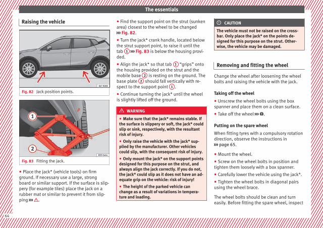
The essentials
Raising the vehicle
Fig. 82 Jack position points.
Fig. 83 Fitting the jack.
● Place the jack* (vehicle tools) on firmground. If necessary use a large, strongboard or similar support. If the surface is slip-pery (for example tiles) place the jack on arubber mat or similar to prevent it from slip-ping ››› .
● Find the support point on the strut (sunkenarea) closest to the wheel to be changed››› Fig. 82.
● Turn the jack* crank handle, located belowthe strut support point, to raise it until thetab 1 ››› Fig. 83 is below the housing provi-ded.
● Align the jack* so that tab 1 “grips” ontothe housing provided on the strut and themobile base 2 is resting on the ground. Thebase plate 2 should fall vertically with re-spect to the support point 1 .
● Continue turning the jack* until the wheelis slightly lifted off the ground.
WARNING
● Make sure that the jack* remains stable. Ifthe surface is slippery or soft, the jack* couldslip or sink, respectively, with the resultantrisk of injury.
● Only raise the vehicle with the jack* sup-plied by the manufacturer. Other vehiclescould slip, with the consequent risk of injury.
● Only mount the jack* on the support pointsdesigned for this purpose on the strut, andalways align the jack correctly. If you do not,the jack* could slip as it does not have an ad-equate grip on the vehicle: risk of injury!
● The height of the parked vehicle canchange as a result of variations in tempera-ture and loading.
CAUTION
The vehicle must not be raised on the cross-bar. Only place the jack* on the points de-signed for this purpose on the strut. Other-wise, the vehicle may be damaged.
Removing and fitting the wheel
Change the wheel after loosening the wheelbolts and raising the vehicle with the jack.
Taking off the wheel
● Unscrew the wheel bolts using the boxspanner and place them on a clean surface.
● Take off the wheel ››› .
Putting on the spare wheel
When fitting tyres with a compulsory rotationdirection, observe the instructions in››› page 65.
● Mount the wheel.
● Screw on the wheel bolts in position andtighten them loosely with a box spanner.
● Carefully lower the vehicle using the jack*.
● Tighten the wheel bolts in diagonal pairsusing the wheel brace.
The wheel bolts should be clean and turneasily. Before fitting the spare wheel, inspect
64
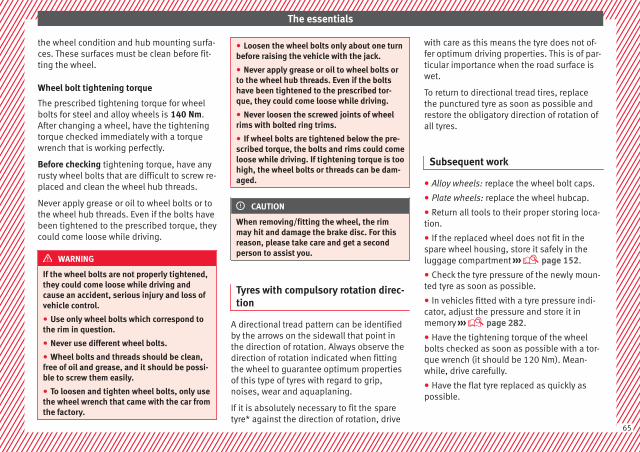
The essentials
the wheel condition and hub mounting surfa-ces. These surfaces must be clean before fit-ting the wheel.
Wheel bolt tightening torque
The prescribed tightening torque for wheelbolts for steel and alloy wheels is 140 Nm.After changing a wheel, have the tighteningtorque checked immediately with a torquewrench that is working perfectly.
Before checking tightening torque, have anyrusty wheel bolts that are difficult to screw re-placed and clean the wheel hub threads.
Never apply grease or oil to wheel bolts or tothe wheel hub threads. Even if the bolts havebeen tightened to the prescribed torque, theycould come loose while driving.
WARNING
If the wheel bolts are not properly tightened,they could come loose while driving andcause an accident, serious injury and loss ofvehicle control.
● Use only wheel bolts which correspond tothe rim in question.
● Never use different wheel bolts.
● Wheel bolts and threads should be clean,free of oil and grease, and it should be possi-ble to screw them easily.
● To loosen and tighten wheel bolts, only usethe wheel wrench that came with the car fromthe factory.
● Loosen the wheel bolts only about one turnbefore raising the vehicle with the jack.
● Never apply grease or oil to wheel bolts orto the wheel hub threads. Even if the boltshave been tightened to the prescribed tor-que, they could come loose while driving.
● Never loosen the screwed joints of wheelrims with bolted ring trims.
● If wheel bolts are tightened below the pre-scribed torque, the bolts and rims could comeloose while driving. If tightening torque is toohigh, the wheel bolts or threads can be dam-aged.
CAUTION
When removing/fitting the wheel, the rimmay hit and damage the brake disc. For thisreason, please take care and get a secondperson to assist you.
Tyres with compulsory rotation direc-tion
A directional tread pattern can be identifiedby the arrows on the sidewall that point inthe direction of rotation. Always observe thedirection of rotation indicated when fittingthe wheel to guarantee optimum propertiesof this type of tyres with regard to grip,noises, wear and aquaplaning.
If it is absolutely necessary to fit the sparetyre* against the direction of rotation, drive
with care as this means the tyre does not of-fer optimum driving properties. This is of par-ticular importance when the road surface iswet.
To return to directional tread tires, replacethe punctured tyre as soon as possible andrestore the obligatory direction of rotation ofall tyres.
Subsequent work
● Alloy wheels: replace the wheel bolt caps.
● Plate wheels: replace the wheel hubcap.
● Return all tools to their proper storing loca-tion.
● If the replaced wheel does not fit in thespare wheel housing, store it safely in theluggage compartment ››› page 152.
● Check the tyre pressure of the newly moun-ted tyre as soon as possible.
● In vehicles fitted with a tyre pressure indi-cator, adjust the pressure and store it inmemory ››› page 282.
● Have the tightening torque of the wheelbolts checked as soon as possible with a tor-que wrench (it should be 120 Nm). Mean-while, drive carefully.
● Have the flat tyre replaced as quickly aspossible.
65
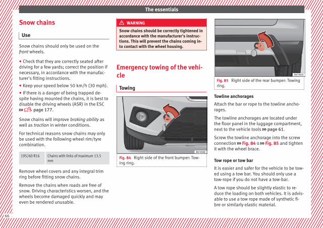
The essentials
Snow chains
Use
Snow chains should only be used on thefront wheels.
● Check that they are correctly seated afterdriving for a few yards; correct the position ifnecessary, in accordance with the manufac-turer's fitting instructions.
● Keep your speed below 50 km/h (30 mph).
● If there is a danger of being trapped de-spite having mounted the chains, it is best todisable the driving wheels (ASR) in the ESC››› page 177.
Snow chains will improve braking ability aswell as traction in winter conditions.
For technical reasons snow chains may onlybe used with the following wheel rim/tyrecombination.
195/60 R16 Chains with links of maximum 13.5mm
Remove wheel covers and any integral trimring before fitting snow chains.
Remove the chains when roads are free ofsnow. Driving characteristics worsen, and thewheels become damaged quickly and mayeven be rendered unusable.
WARNING
Snow chains should be correctly tightened inaccordance with the manufacturer's instruc-tions. This will prevent the chains coming in-to contact with the wheel housing.
Emergency towing of the vehi-cle
Towing
Fig. 84 Right side of the front bumper: Tow-ing ring.
Fig. 85 Right side of the rear bumper: Towingring.
Towline anchorages
Attach the bar or rope to the towline ancho-rages.
The towline anchorages are located underthe floor panel in the luggage compartment,next to the vehicle tools ››› page 61.
Screw the towline anchorage into the screwconnection ››› Fig. 84 o ››› Fig. 85 and tightenit with the wheel brace.
Tow rope or tow bar
It is easier and safer for the vehicle to be tow-ed using a tow bar. You should only use atow-rope if you do not have a tow-bar.
A tow rope should be slightly elastic to re-duce the loading on both vehicles. It is advis-able to use a tow rope made of synthetic fi-bre or similarly elastic material.
66
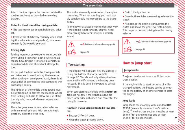
The essentials
Attach the tow rope or the tow bar only to thetowline anchorages provided or a towingbracket.
Notes for the driver of the towing vehicle
● The tow rope must be taut before you driveoff.
● Release the clutch very carefully when start-ing the vehicle (manual gearbox), or acceler-ate gently (automatic gearbox).
Driving style
Towing requires some experience, especiallywhen using a tow rope. Both drivers shouldrealise how difficult it is to tow a vehicle. In-experienced drivers should not attempt totow.
Do not pull too hard with the towing vehicleand take care to avoid jerking the tow rope.When towing on an unpaved road, there is al-ways a risk of overloading and damaging theanchorage points.
The ignition of the vehicle being towed mustbe switched on to prevent the steering wheelfrom locking and also to allow the use of theturn signals, horn, windscreen wipers andwashers.
Place the gear lever in neutral on vehicleswith a manual gearbox. With an automaticgearbox, place the lever in N.
The brake servo only works when the engineis running. When not running, you must ap-ply considerably more pressure to the brakepedal.
As the power assisted steering does not workif the engine is not running, you will needmore strength to steer than you normallywould.
››› in General information on page 96
››› page 96
Tow-starting
If the engine will not start, first try starting itusing the battery of another vehicle››› page 67. You should only attempt to tow-start a vehicle if charging the battery doesnot work. This is done by leveraging wheelmovement.
When tow-starting a vehicle with a petrol en-gine, do not tow it more than a short dis-tance, otherwise unburned fuel can enter thecatalytic converter.
However, if your vehicle has to be tow-star-ted:
● Engage 2nd or 3rd gear.
● Keep the clutch pressed down.
● Switch the ignition on.
● Once both vehicles are moving, release theclutch.
● As soon as the engine starts, press theclutch and move the gear lever into neutral.This helps to prevent driving into the towingvehicle.
››› in General information on page 96
››› page 96
How to jump start
Jump leads
The jump lead must have a sufficient wirecross section.
If the engine fails to start because of a dis-charged battery, the battery can be connec-ted to the battery of another vehicle to startthe engine.
Jump leads
Jump leads must comply with standard DIN72553 (see cable manufacturer's instruc-tions). The wire cross section must be at least25 mm2 for petrol engines and at least35 mm2 for diesel engines. »
67
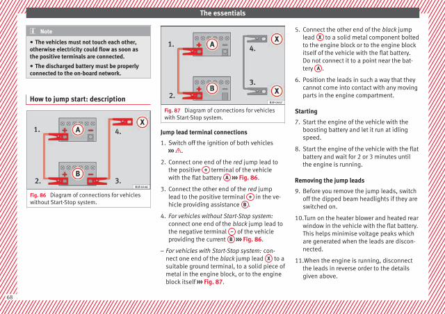
The essentials
Note
● The vehicles must not touch each other,otherwise electricity could flow as soon asthe positive terminals are connected.
● The discharged battery must be properlyconnected to the on-board network.
How to jump start: description
Fig. 86 Diagram of connections for vehicleswithout Start-Stop system.
Fig. 87 Diagram of connections for vehicleswith Start-Stop system.
Jump lead terminal connections
1. Switch off the ignition of both vehicles››› .
2. Connect one end of the red jump lead tothe positive + terminal of the vehiclewith the flat battery A ››› Fig. 86.
3. Connect the other end of the red jumplead to the positive terminal + in the ve-hicle providing assistance B .
4. For vehicles without Start-Stop system:connect one end of the black jump lead tothe negative terminal – of the vehicleproviding the current B ››› Fig. 86.
– For vehicles with Start-Stop system: con-nect one end of the black jump lead X to asuitable ground terminal, to a solid piece ofmetal in the engine block, or to the engineblock itself ››› Fig. 87.
5. Connect the other end of the black jumplead X to a solid metal component boltedto the engine block or to the engine blockitself of the vehicle with the flat battery.Do not connect it to a point near the bat-tery A .
6. Position the leads in such a way that theycannot come into contact with any movingparts in the engine compartment.
Starting
7. Start the engine of the vehicle with theboosting battery and let it run at idlingspeed.
8. Start the engine of the vehicle with the flatbattery and wait for 2 or 3 minutes untilthe engine is running.
Removing the jump leads
9. Before you remove the jump leads, switchoff the dipped beam headlights if they areswitched on.
10.Turn on the heater blower and heated rearwindow in the vehicle with the flat battery.This helps minimise voltage peaks whichare generated when the leads are discon-nected.
11.When the engine is running, disconnectthe leads in reverse order to the detailsgiven above.
68

The essentials
Make sure the battery clamps have sufficientmetal-to-metal contact with the battery termi-nals.
If the engine fails to start, switch off the start-er after about 10 seconds and try again afterabout a minute.
WARNING
● Please note the safety warnings referring toworking in the engine compartment››› page 267, Working in the enginecompartment.
● The battery providing assistance must havethe same voltage as the flat battery (12 V)and approximately the same capacity (seeimprint on battery). Failure to comply couldresult in an explosion.
● Never use jump leads when one of the bat-teries is frozen. Danger of explosion! Even af-ter the battery has thawed, battery acid couldleak and cause chemical burns. If a batteryfreezes, it should be replaced.
● Keep sparks, flames and lighted cigarettesaway from batteries, danger of explosion.Failure to comply could result in an explo-sion.
● Observe the instructions provided by themanufacturer of the jump leads.
● Do not connect the negative cable from theother vehicle directly to the negative terminalof the flat battery. The gas emitted from thebattery could be ignited by sparks. Danger ofexplosion.
● Never attach the negative cable to fuel sys-tem components or the brake lines in the oth-er vehicle.
● The non-insulated parts of the batteryclamps must not be allowed to touch. Thejump lead attached to the positive batteryterminal must not touch metal parts of the ve-hicle, this can cause a short circuit.
● Position the leads in such a way that theycannot come into contact with any movingparts in the engine compartment.
● Do not lean on the batteries. This could re-sult in chemical burns.
Note
The vehicles must not touch each other, oth-erwise electricity could flow as soon as thepositive terminals are connected.
Changing the windscreen wiperblades
Changing the wiper blades
Fig. 88 Wipers in service position.
Fig. 89 Changing the windscreen wiperblade.
To change the blades it is necessary to movethe wipers from the rest position into theservice position. »
69
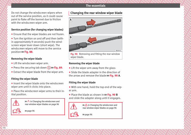
The essentials
Do not change the windscreen wipers whenout of the service position, as it could causepaint to flake off the bonnet due to frictionwith the windscreen wiper arm.
Service position (for changing wiper blades)
● Ensure that the wiper blades are not frozen.
● Turn the ignition on and off and then (with-in approximately 9 seconds) push the wind-screen wiper lever down (short wipe). Thewindscreen wipers will move to the serviceposition ››› Fig. 88.
Removing the wiper blade
● Lift the windscreen wiper arm.
● Press the securing tab down 1 ››› Fig. 89.
● Extract the wiper blade from the wiper arm.
Fitting the wiper blade
● Insert the wiper blade onto the windscreenwiper arm until it clicks into place.
● Place the windscreen wiper arms to their in-itial position.
››› in Changing the windscreen andrear window wiper blades on page 96
››› page 96
Changing the rear window wiper blade
Fig. 90 Removing and fitting the rear windowwiper blade.
Removing the wiper blade
● Lift the wiper arm away from the glass
● Slide the blade adapter in the direction ofthe arrow and remove the blade ››› Fig. 90 A.
Fitting the wiper blade
● With one hand, hold the top end of the wip-er arm.
● Place the blade as shown in ››› Fig. 90 Band slide the adapter along until it engages.
››› in Changing the windscreen andrear window wiper blades on page 96
››› page 96
70

Safe driving
Safety
Safe driving
Safety first!
This chapter contains important information,tips, suggestions and warnings that youshould read and consider for both your ownsafety and for your passengers' safety.
WARNING
● This manual contains important informa-tion about the operation of the vehicle, bothfor the driver and the passengers. The othersections of the on-board documentation alsocontain further information that you shouldbe aware of for your own safety and for thesafety of your passengers.
● Ensure that the on-board documentation iskept in the vehicle at all times. This is espe-cially important when lending or selling thevehicle to another person.
Advice about driving
Before setting off
For your own safety and the safety of yourpassengers, always note the following pointsbefore every trip:
– Make sure that the vehicle's lights and turnsignals are working properly.
– Check tyre pressure.
– Ensure that all windows provide a clear andgood view of the surroundings.
– Ensure that all luggage is correctly secured››› page 152.
– Make sure that no objects can interferewith the pedals.
– Adjust front seat, head restraint and mir-rors properly according to your size.
– Ensure that the passenger in the centralrear seat always has the head restraint inthe correct position for use.
– Instruct passengers to adjust the head re-straints according to their height.
– Protect children with appropriate childseats and properly applied seat belts››› page 88.
– Assume the correct sitting position. Instructyour passengers also to assume a propersitting position ››› page 72.
– Fasten your seat belt securely. Instruct yourpassengers also to fasten their seat beltsproperly ››› page 77.
What affects driving safety?
As a driver, you are responsible for yourselfand your passengers. When your concentra-tion or driving safety is affected by any cir-cumstance, you endanger yourself as well asothers on the road ››› , for this reason:
– Always pay attention to traffic and do notget distracted by passengers or telephonecalls.
– Never drive when your driving ability is im-paired (e.g. by medication, alcohol, drugs).
– Observe traffic laws and speed limits.
– Always reduce your speed as appropriatefor road, traffic and weather conditions.
– When travelling long distances, takebreaks regularly - at least every two hours.
– If possible, avoid driving when you are tiredor stressed.
WARNING
When driving safety is impaired during a trip,the risk of injury and accidents increases.
Safety equipment
Never put your safety or the safety of yourpassengers in danger. In the event of an acci-dent, the safety equipment may reduce the »
71
Tech
nica
l dat
aA
dvic
eO
pera
tion
Emer
genc
ies
Saf
ety

Safety
risk of injury. The following list includes mostof the safety equipment in your SEAT:
● three-point seat belts,
● Belt tension limiter for the front and rearside seats
● Belt tensioners for the front seats,
● front airbags,
● Side airbags in the front seat backrests,with chest and head protection
● “ISOFIX” anchor points for “ISOFIX” rearchild seat system
● height-adjustable front head restraints,
● Rear-centre head restraints with in-use po-sition and non-use position
● adjustable steering column.
The safety equipment mentioned aboveworks together to provide you and your pas-sengers with the best possible protection inthe event of an accident. However, thesesafety systems can only be effective if youand your passengers are sitting in a correctposition and use this equipment properly.
Safety is everyone's business!
Correct position for passengers
Correct sitting position for driver
Fig. 91 The proper distance between driverand steering wheel.
Fig. 92 Correct head restraint position for thedriver.
For your own safety and to reduce the risk ofinjury in the event of an accident, we recom-
mend the following adjustments for the driv-er:
– Adjust the steering wheel so that there is adistance of at least 25 cm between thesteering wheel and the centre of your chest››› Fig. 91.
– Move the driver's seat forwards or back-wards so that you are able to press the ac-celerator, brake and clutch pedals to thefloor with your knees still slightly angled››› .
– Ensure that you can reach the highest pointof the steering wheel.
– Adjust the head restraint so that its upperedge is at the same level as the top of yourhead, or as close as possible to the samelevel as the top of your head ››› Fig. 92.
– Move the seat backrest to an upright posi-tion so that your back rests completelyagainst it.
– Fasten your seat belt securely ››› page 77.
– Keep both feet in the footwell so that youhave the vehicle under control at all times.
Adjustment of the driver's seat ››› page 146.
WARNING
● An incorrect sitting position of the drivercan lead to severe injuries.
72
Safe driving
● Adjust the driver's seat so that there is atleast 25 cm distance between the centre ofthe chest and the centre of the steeringwheel ››› Fig. 91. If distance is less than 25cm, the airbag system may not protect youproperly.
● If your physical constitution prevents youfrom maintaining the minimum distance of 25cm, contact a specialised workshop. Theworkshop will help you decide if special spe-cific modifications are necessary.
● When driving, always hold the steeringwheel with both hands on the outside of thering at the 9 o'clock and 3 o'clock positions.This reduces the risk of injury when the driverairbag is triggered.
● Never hold the steering wheel at the 12o'clock position, or in any other manner (e.g.in the centre of the steering wheel). In suchcases, if the airbag is triggered, you may sus-tain injuries to the arms, hands and head.
● To reduce the risk of injury to the driverduring sudden braking manoeuvres or an ac-cident, never drive with the backrest tilted farback! The airbag system and seat belts canonly provide optimal protection when thebackrest is in an upright position and thedriver is wearing his or her seat belt correct-ly.
● Adjust the head restraint properly to ach-ieve optimal protection.
Adjusting the steering wheel position
Read the additional information carefully››› page 20
WARNING
● Never adjust the position of the steeringwheel when the vehicle is moving, as thiscould cause an accident.
● Move the lever up firmly so the steeringwheel position does not accidentally changeduring driving. risk of accident!
● Make sure you are capable of reaching andfirmly holding the upper part of the steeringwheel: risk of accident!
● If you adjust the steering wheel so that itpoints towards your face, the driver airbagwill not protect you properly in the event ofan accident. Make sure that the steeringwheel points towards your chest.
Correct sitting position for front pas-senger
For your own safety and to reduce the risk ofinjury in the event of an accident, we recom-mend the following adjustments for the frontpassenger:
– Move the front passenger seat back as faras possible ››› .
– Move the seat backrest to an upright posi-tion so that your back rests completelyagainst it.
– Adjust the head restraint so that its upperedge is at the same level as the top of yourhead, or as close as possible to the samelevel as the top of your head ››› page 75.
– Always keep both feet in the footwell infront of the front passenger seat.
– Fasten your seat belt securely ››› page 77.
It is possible to deactivate the front passen-ger airbag in exceptional circumstances››› page 86.
Adjusting the front passenger seat››› page 18.
WARNING
● An incorrect sitting position of the frontpassenger can lead to severe injuries.
● Adjust the front passenger seat so thatthere is at least 25 cm between your chestand the dash panel. If distance is less than25 cm, the airbag system may not protect youproperly.
● If your physical constitution prevents youfrom maintaining the minimum distance of 25cm, contact a specialised workshop. Theworkshop will help you decide if special spe-cific modifications are necessary. »
73
Tech
nica
l dat
aA
dvic
eO
pera
tion
Emer
genc
ies
Saf
ety
Safety
● Always keep your feet in the footwell whenthe vehicle is moving; never rest them on thedash panel, out the window or on the seat. Anincorrect sitting position exposes you to anincreased risk of injury in case of a suddenbraking or an accident. If the airbag is trig-gered, you could sustain severe injuries dueto an incorrect sitting position.
● To reduce the risk of injury to the front pas-senger in events such as sudden braking ma-noeuvres or an accident, never travel with thebackrest tilted far back! The airbag systemand seat belts can only provide optimal pro-tection when the backrest is in an upright po-sition and the front passenger is wearing hisor her seat belt properly. The further the seatbackrests are tilted to the rear, the greaterthe risk of injury due to incorrect positioningof the belt web or to the incorrect sitting po-sition!
● Adjust the head restraint correctly in orderto achieve maximum protection.
Correct sitting position for rear seatpassengers
To reduce the risk of injury in the event of asudden braking manoeuvre or an accident,passengers on the rear seat bench must con-sider the following:
– Sit up straight.
– Adjust the head restraint to the correct po-sition ››› page 75.
– Always keep both feet in the footwell infront of the rear seat.
– Fasten your seat belt securely ››› page 77.
– Use an appropriate child restraint systemwhen you take children in the vehicle››› page 88.
WARNING
● If the passengers in the rear seats are notsitting properly, they could sustain severe in-juries.
● Adjust the head restraint correctly in orderto achieve maximum protection.
● Seat belts can only provide optimal protec-tion when seat backrests are in an uprightposition and the vehicle occupants are wear-ing their seat belts correctly. If passengers Inthe rear seats are not sitting in an upright po-sition, the risk of injury due to incorrect posi-tioning of the seat belt increases.
Examples of incorrect sitting posi-tions
Seat belts can provide optimal protection on-ly when the belt webs are properly posi-tioned. Incorrect sitting positions substan-tially reduce the protective function of seatbelts and increase the risk of injury due to in-correct seat belt position. As the driver, youare responsible for all passengers, especiallychildren.
– Never allow anyone to assume an incorrectsitting position in the vehicle while travel-ling ››› .
The following list contains examples of sit-ting positions that could be dangerous for allvehicle occupants. The list is not complete,but we would like to make you aware of thisissue.
Therefore, whenever the vehicle is in motion:
● Never stand in the vehicle.
● Never stand on the seats.
● Never kneel on the seats.
● Never tilt your seat backrest far to the rear.
● Never lean against the dash panel.
● Never lie on the rear bench.
● Never sit on the front edge of a seat.
● Never sit sideways.
● Never lean out of a window.
● Never put your feet out of a window.
● Never put your feet on the dash panel.
● Never put your feet on the surface of a seat.
● Do not allow anyone to travel in the foot-well.
● Never travel without wearing the seat belt.
● Do not allow anyone to travel in the lug-gage compartment.
74
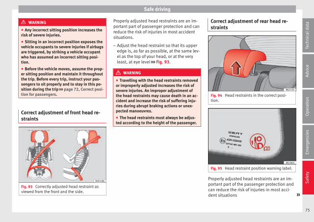
Safe driving
WARNING
● Any incorrect sitting position increases therisk of severe injuries.
● Sitting in an incorrect position exposes thevehicle occupants to severe injuries if airbagsare triggered, by striking a vehicle occupantwho has assumed an incorrect sitting posi-tion.
● Before the vehicle moves, assume the prop-er sitting position and maintain it throughoutthe trip. Before every trip, instruct your pas-sengers to sit properly and to stay in this po-sition during the trip ››› page 72, Correct posi-tion for passengers.
Correct adjustment of front head re-straints
Fig. 93 Correctly adjusted head restraint asviewed from the front and the side.
Properly adjusted head restraints are an im-portant part of passenger protection and canreduce the risk of injuries in most accidentsituations.
– Adjust the head restraint so that its upperedge is, as far as possible, at the same lev-el as the top of your head, or at the veryleast, at eye level ››› Fig. 93.
WARNING
● Travelling with the head restraints removedor improperly adjusted increases the risk ofsevere injuries. An improper adjustment ofthe head restraints may cause death in an ac-cident and increase the risk of suffering inju-ries during abrupt braking actions or unex-pected manoeuvres.
● The head restraints must always be adjus-ted according to the height of the passenger.
Correct adjustment of rear head re-straints
Fig. 94 Head restraints in the correct posi-tion.
Fig. 95 Head restraint position warning label.
Properly adjusted head restraints are an im-portant part of the passenger protection andcan reduce the risk of injuries in most acci-dent situations »
75
Tech
nica
l dat
aA
dvic
eO
pera
tion
Emer
genc
ies
Saf
ety
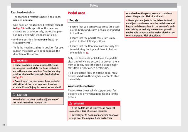
Safety
Rear head restraints
– The rear head restraints have 2 positions:use and non-use.
– One position for use (head restraint raised)››› Fig. 94. In this position, the head re-straints are used normally, protecting pas-sengers along with the rear seat belts.
– And one position for non-use (head re-straint lowered).
– To fit the head restraints in position for use,pull on the edges with both hands in thedirection of the arrow.
WARNING
● Under no circumstances should the rearpassengers travel while the head restraintsare in the non-use position. See the warninglabel located on the rear side fixed window››› Fig. 95.
● Do not swap the centre rear head restraintwith either of the outer seat rear head re-straints. Risk of injury in case of an accident!
CAUTION
Note the instructions on the adjustment ofthe head restraints ››› page 146.
Pedal area
Pedals
– Ensure that you can always press the accel-erator, brake and clutch pedals unimpairedto the floor.
– Ensure that the pedals can return unim-paired to their initial positions.
– Ensure that the floor mats are securely fas-tened during the trip and do not obstructthe pedals ››› .
Only use floor mats which leave the pedalsclear and which are secured to prevent themfrom slipping. You can obtain suitable floormats from a specialised dealership.
If a brake circuit fails, the brake pedal mustbe pressed down thoroughly in order to stopthe vehicle.
Wear suitable footwear
Always wear shoes which support your feetproperly and give you a good feeling for thepedals.
WARNING
● If the pedals are obstructed, an accidentmay occur. Risk of serious injuries.
● Never lay or fit floor mats or other floor cov-erings over the original floor mats. This
would reduce the pedal area and could ob-struct the pedals. Risk of accident.
● Never place objects in the driver footwell.An object could move into the pedal area andimpair pedal operation. In the event of a sud-den driving or braking manoeuvre, you willnot be able to operate the brake, clutch or ac-celerator pedal. Risk of accident!
76
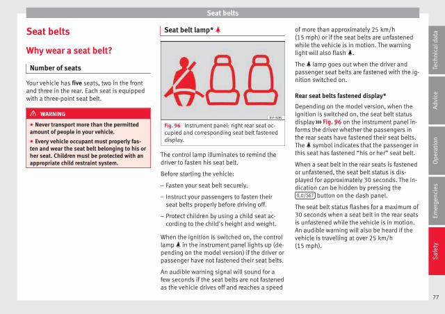
Seat belts
Seat belts
Why wear a seat belt?
Number of seats
Your vehicle has five seats, two in the frontand three in the rear. Each seat is equippedwith a three-point seat belt.
WARNING
● Never transport more than the permittedamount of people in your vehicle.
● Every vehicle occupant must properly fas-ten and wear the seat belt belonging to his orher seat. Children must be protected with anappropriate child restraint system.
Seat belt lamp*
Fig. 96 Instrument panel: right rear seat oc-cupied and corresponding seat belt fasteneddisplay.
The control lamp illuminates to remind thedriver to fasten his seat belt.
Before starting the vehicle:
– Fasten your seat belt securely.
– Instruct your passengers to fasten theirseat belts properly before driving off.
– Protect children by using a child seat ac-cording to the child's height and weight.
When the ignition is switched on, the controllamp in the instrument panel lights up (de-pending on the model version) if the driver orpassenger have not fastened their seat belts.
An audible warning signal will sound for afew seconds if the seat belts are not fastenedas the vehicle drives off and reaches a speed
of more than approximately 25 km/h(15 mph) or if the seat belts are unfastenedwhile the vehicle is in motion. The warninglight will also flash .
The lamp goes out when the driver andpassenger seat belts are fastened with the ig-nition switched on.
Rear seat belts fastened display*
Depending on the model version, when theignition is switched on, the seat belt statusdisplay ››› Fig. 96 on the instrument panel in-forms the driver whether the passengers inthe rear seats have fastened their seat belts.The symbol indicates that the passenger inthis seat has fastened “his or her” seat belt.
When a seat belt in the rear seats is fastenedor unfastened, the seat belt status is dis-played for approximately 30 seconds. The in-dication can be hidden by pressing the0.0/SET button on the dash panel.
The seat belt status flashes for a maximum of30 seconds when a seat belt in the rear seatsis unfastened while the vehicle is in motion.An audible warning will also be heard if thevehicle is travelling at over 25 km/h(15 mph).
77
Tech
nica
l dat
aA
dvic
eO
pera
tion
Emer
genc
ies
Saf
ety

Safety
The protective function of seat belts
Fig. 97 Drivers with properly worn seat beltswill not be thrown forward in the event of sud-den braking.
Properly worn seat belts hold the occupantsin the proper position. These also help pre-vent uncontrolled movements that may resultin serious injury and reduce the risk of beingthrown out of the vehicle.
Vehicle occupants wearing their seat beltscorrectly benefit greatly from the ability of thebelts to absorb kinetic energy. In addition,the front part of your vehicle and other pas-sive safety features (such as the airbag sys-tem) are designed to absorb the kinetic ener-gy released in a collision. Taken together, allthese features reduce the releasing kineticenergy and consequently, the risk of injury.This is why it is so important to fasten seatbelts before every trip, even when "just driv-ing around the corner".
Ensure that your passengers wear their seatbelts as well. Accident statistics have shownthat wearing seat belts is an effective meansof substantially reducing the risk of injuryand improving the chances of survival wheninvolved in a serious accident. Furthermore,properly worn seat belts improve the protec-tion provided by airbags in the event of anaccident. For this reason, wearing a seat beltis required by law in most countries.
Although your vehicle is equipped with air-bags, the seat belts must be fastened andworn. The front airbags, for example, are onlytriggered in some cases of head-on collision.The front airbags will not be triggered duringminor frontal or side collisions, rear-end colli-sions, rollovers or accidents in which the air-bag trigger threshold value in the control unitis not exceeded.
Therefore, you should always wear your seatbelt and ensure that all vehicle occupantshave fastened their seat belts properly beforeyou drive off!
Safety instructions on using seatbelts
– Always wear the seat belt as described inthis section.
– Ensure that the seat belts can be fastenedat all times and are not damaged.
WARNING
● If seat belts are worn incorrectly or not atall, the risk of severe injuries increases. Theoptimal protection from seat belts can beachieved only if you use them properly.
● Fasten your seat belt before every trip -even when driving in town. Other vehicle oc-cupants must also wear the seat belts at alltimes, otherwise they run the risk of being in-jured.
● The seat belt cannot offer its full protectionif the seat belt is not positioned correctly.
● Never allow two passengers (even children)to share the same seat belt.
● Always keep both feet in the footwell infront of your seat as long as the vehicle is inmotion.
● Never unbuckle a seat belt while the vehi-cle is in motion. Risk of fatal injury.
● The seat belt must never be twisted while itis being worn.
● The seat belt should never lie on hard orfragile objects (such as glasses or pens, etc.)because this can cause injuries.
● Do not allow the seat belt to be damaged orjammed, or to rub on any sharp edges.
● Never wear the seat belt under the arm orin any other incorrect position.
● Loose, bulky clothing (such as an overcoatover a jacket) impairs the proper fit and func-tion of the seat belts, reducing their capacityto protect.
78
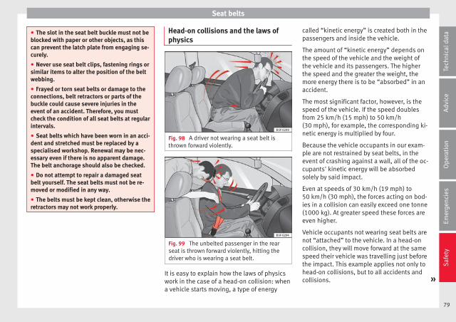
Seat belts
● The slot in the seat belt buckle must not beblocked with paper or other objects, as thiscan prevent the latch plate from engaging se-curely.
● Never use seat belt clips, fastening rings orsimilar items to alter the position of the beltwebbing.
● Frayed or torn seat belts or damage to theconnections, belt retractors or parts of thebuckle could cause severe injuries in theevent of an accident. Therefore, you mustcheck the condition of all seat belts at regularintervals.
● Seat belts which have been worn in an acci-dent and stretched must be replaced by aspecialised workshop. Renewal may be nec-essary even if there is no apparent damage.The belt anchorage should also be checked.
● Do not attempt to repair a damaged seatbelt yourself. The seat belts must not be re-moved or modified in any way.
● The belts must be kept clean, otherwise theretractors may not work properly.
Head-on collisions and the laws ofphysics
Fig. 98 A driver not wearing a seat belt isthrown forward violently.
Fig. 99 The unbelted passenger in the rearseat is thrown forward violently, hitting thedriver who is wearing a seat belt.
It is easy to explain how the laws of physicswork in the case of a head-on collision: whena vehicle starts moving, a type of energy
called “kinetic energy” is created both in thepassengers and inside the vehicle.
The amount of “kinetic energy” depends onthe speed of the vehicle and the weight ofthe vehicle and its passengers. The higherthe speed and the greater the weight, themore energy there is to be “absorbed” in anaccident.
The most significant factor, however, is thespeed of the vehicle. If the speed doublesfrom 25 km/h (15 mph) to 50 km/h(30 mph), for example, the corresponding ki-netic energy is multiplied by four.
Because the vehicle occupants in our exam-ple are not restrained by seat belts, in theevent of crashing against a wall, all of the oc-cupants' kinetic energy will be absorbedsolely by said impact.
Even at speeds of 30 km/h (19 mph) to50 km/h (30 mph), the forces acting on bod-ies in a collision can easily exceed one tonne(1000 kg). At greater speed these forces areeven higher.
Vehicle occupants not wearing seat belts arenot “attached” to the vehicle. In a head-oncollision, they will move forward at the samespeed their vehicle was travelling just beforethe impact. This example applies not only tohead-on collisions, but to all accidents andcollisions. »
79
Tech
nica
l dat
aA
dvic
eO
pera
tion
Emer
genc
ies
Saf
ety

Safety
Even at low speeds the forces acting on thebody in a collision are so great that it is notpossible to brace oneself with one's hands.In a frontal collision, unbelted passengersare thrown forward and will make violent con-tact with the steering wheel, dash panel,windscreen or whatever else is in the way››› Fig. 98.
It is also important for rear passengers towear seat belts properly, as they could other-wise be thrown forward violently through thevehicle interior in an accident. Passengers inthe rear seats who do not use seat belts en-danger not only themselves but also the frontoccupants ››› Fig. 99.
How to properly adjust yourseatbelt
Fastening and unfastening the seatbelt
Fig. 100 Positioning and removing the seatbelt buckle.
Fig. 101 Position of seat belt during pregnan-cy.
Read the additional information carefully››› page 19.
Fasten your seat belt
The seat belt cannot offer its full protection ifthe seat belt is not positioned correctly.
● Adjust the seat and head restraint correctly.
● To fasten the belt, take hold of the latchplate and pull it slowly across your chest andlap.
● Insert the latch plate into the buckle for theappropriate seat and push it down until it issecurely locked with an audible click››› Fig. 100.
● Pull the belt to ensure that the latch plate issecurely engaged in the buckle.
80
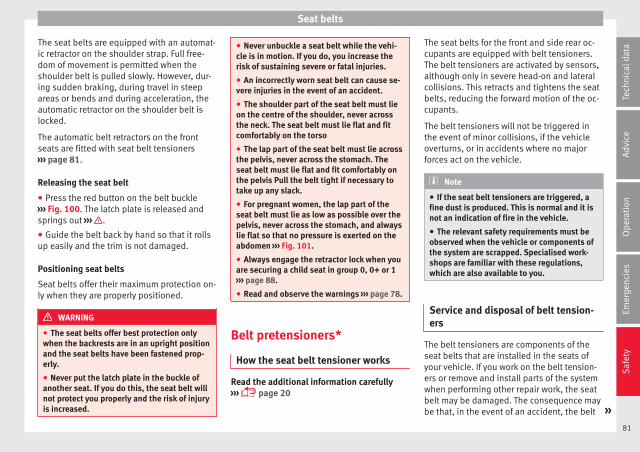
Seat belts
The seat belts are equipped with an automat-ic retractor on the shoulder strap. Full free-dom of movement is permitted when theshoulder belt is pulled slowly. However, dur-ing sudden braking, during travel in steepareas or bends and during acceleration, theautomatic retractor on the shoulder belt islocked.
The automatic belt retractors on the frontseats are fitted with seat belt tensioners››› page 81.
Releasing the seat belt
● Press the red button on the belt buckle››› Fig. 100. The latch plate is released andsprings out ››› .
● Guide the belt back by hand so that it rollsup easily and the trim is not damaged.
Positioning seat belts
Seat belts offer their maximum protection on-ly when they are properly positioned.
WARNING
● The seat belts offer best protection onlywhen the backrests are in an upright positionand the seat belts have been fastened prop-erly.
● Never put the latch plate in the buckle ofanother seat. If you do this, the seat belt willnot protect you properly and the risk of injuryis increased.
● Never unbuckle a seat belt while the vehi-cle is in motion. If you do, you increase therisk of sustaining severe or fatal injuries.
● An incorrectly worn seat belt can cause se-vere injuries in the event of an accident.
● The shoulder part of the seat belt must lieon the centre of the shoulder, never acrossthe neck. The seat belt must lie flat and fitcomfortably on the torso
● The lap part of the seat belt must lie acrossthe pelvis, never across the stomach. Theseat belt must lie flat and fit comfortably onthe pelvis Pull the belt tight if necessary totake up any slack.
● For pregnant women, the lap part of theseat belt must lie as low as possible over thepelvis, never across the stomach, and alwayslie flat so that no pressure is exerted on theabdomen ››› Fig. 101.
● Always engage the retractor lock when youare securing a child seat in group 0, 0+ or 1››› page 88.
● Read and observe the warnings ››› page 78.
Belt pretensioners*
How the seat belt tensioner works
Read the additional information carefully››› page 20
The seat belts for the front and side rear oc-cupants are equipped with belt tensioners.The belt tensioners are activated by sensors,although only in severe head-on and lateralcollisions. This retracts and tightens the seatbelts, reducing the forward motion of the oc-cupants.
The belt tensioners will not be triggered inthe event of minor collisions, if the vehicleoverturns, or in accidents where no majorforces act on the vehicle.
Note
● If the seat belt tensioners are triggered, afine dust is produced. This is normal and it isnot an indication of fire in the vehicle.
● The relevant safety requirements must beobserved when the vehicle or components ofthe system are scrapped. Specialised work-shops are familiar with these regulations,which are also available to you.
Service and disposal of belt tension-ers
The belt tensioners are components of theseat belts that are installed in the seats ofyour vehicle. If you work on the belt tension-ers or remove and install parts of the systemwhen performing other repair work, the seatbelt may be damaged. The consequence maybe that, in the event of an accident, the belt »
81
Tech
nica
l dat
aA
dvic
eO
pera
tion
Emer
genc
ies
Saf
ety

Safety
tensioners function incorrectly or may notfunction at all.
So that the effectiveness of the seat belt ten-sioner is not reduced and that removed partsdo not cause any injuries or environmentalpollution, regulations, which are known tothe specialised workshops, must be ob-served.
WARNING
● Improper use or repairs not carried out byqualified mechanics increase the risk of se-vere or fatal injuries. The belt tensioners mayfail to trigger or may trigger in the wrong cir-cumstances.
● Never attempt to repair, adjust, remove orinstall parts of the belt tensioners or seatbelts.
● The seat belt tensioner, seat belt and auto-matic retractor cannot be repaired.
● Any work on the belt tensioners and seatbelts, including the removal and refitting ofsystem parts in conjunction with other repairwork, must be performed by a specialisedworkshop only.
● The belt tensioners will only provide pro-tection for one accident and must be changedif they have been activated.
Airbag system
Brief introduction
Why is it so important to wear a seatbelt and to sit correctly?
For the inflating airbags to achieve the bestprotection, the seat belt must always be wornproperly and the correct sitting position mustbe assumed.
The airbag system is not a substitute for seatbelts, but it is an integral part of the vehicle'soverall passive safety system. Please bear inmind that the airbag system can only work ef-fectively when the vehicle occupants arewearing their seat belts correctly and haveadjusted the head restraints properly. There-fore, it is most important to properly wear theseat belts at all times, not only because thisis required by law in most countries, but alsofor your safety ››› page 77, Why wear a seatbelt?.
The airbag inflates in a matter of seconds, soif you are not properly seated when the air-bag is triggered, you may sustain fatal inju-ries. Therefore, it is essential that all vehicleoccupants assume a correct sitting positionwhile travelling.
Sharp braking before an accident may causea passenger not wearing a seat belt to bethrown forward into the area of the deploying
airbag. In this case, the inflating airbag mayinflict critical or fatal injuries on the occu-pant. This also applies to children.
Always maintain the greatest possible dis-tance between yourself and the front airbag.This way, the front airbags can completelydeploy when triggered, providing their maxi-mum protection.
The most important factors that will triggeran airbag are: the type of accident, the angleof collision and the speed of the vehicle.
Whether or not the airbags are triggered de-pends primarily on the vehicle decelerationrate resulting from the collision and detectedby the control unit. If the vehicle decelerationoccurring during the collision and measuredby the control unit remains below the speci-fied reference values, the front, side and/orcurtain airbags will not be triggered. Take in-to account that the visible damage in a vehi-cle involved in an accident, no matter howserious, is not a determining factor for theairbags to have been triggered.
WARNING
● Wearing the seat belt incorrectly or assum-ing an incorrect sitting position can lead tocritical or fatal injuries.
● All vehicle occupants, including children,who are not properly belted can sustain criti-cal or fatal injuries if the airbag is triggered.Children up to 12 years old should always
82
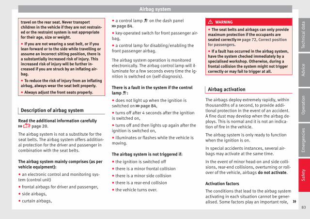
Airbag system
travel on the rear seat. Never transportchildren in the vehicle if they are not restrain-ed or the restraint system is not appropriatefor their age, size or weight.
● If you are not wearing a seat belt, or if youlean forward or to the side while travelling orassume an incorrect sitting position, there isa substantially increased risk of injury. Thisincreased risk of injury will be further in-creased if you are struck by an inflating air-bag.
● To reduce the risk of injury from an inflatingairbag, always wear the seat belt properly.
● Always adjust the front seats properly.
Description of airbag system
Read the additional information carefully››› page 20.
The airbag system is not a substitute for theseat belts. The airbag system offers addition-al protection for the driver and passenger incombination with the seat belts.
The airbag system mainly comprises (as pervehicle equipment):
● an electronic control and monitoring sys-tem (control unit)
● frontal airbags for driver and passenger,
● side airbags,
● curtain airbags,
● a control lamp on the dash panel››› page 84.
● key-operated switch for front passenger air-bag,
● a control lamp for disabling/enabling thefront passenger airbag.
The airbag system operation is monitoredelectronically. The airbag control lamp will il-luminate for a few seconds every time the ig-nition is switched on (self-diagnosis).
There is a fault in the system if the controllamp :
● does not light up when the ignition isswitched on ››› page 84,
● turns off after 4 seconds after the ignitionis switched on,
● turns off and then lights up again after theignition is switched on,
● illuminates or flashes while the vehicle ismoving.
The airbag system is not triggered if:
● the ignition is switched off
● there is a minor frontal collision
● there is a minor side collision
● there is a rear-end collision
● the vehicle turns over.
WARNING
● The seat belts and airbags can only providemaximum protection if the occupants areseated correctly ››› page 72, Correct positionfor passengers.
● If a fault has occurred in the airbag system,have the system checked immediately by aspecialised workshop. Otherwise, during afrontal collision the system might not triggercorrectly or may fail to trigger at all.
Airbag activation
The airbags deploy extremely rapidly, withinthousandths of a second, to provide addi-tional protection in the event of an accident.A fine dust may develop when the airbag de-ploys. This is normal and it is not an indica-tion of fire in the vehicle.
The airbag system is only ready to functionwhen the ignition is on.
In special accidents instances, several air-bags may activate at the same time.
In the event of minor head-on and side colli-sions, rear-end collisions, overturning or roll-over of the vehicle, airbags do not activate.
Activation factors
The conditions that lead to the airbag systemactivating in each situation cannot be gener-alised. Some factors play an important role, »
83
Tech
nica
l dat
aA
dvic
eO
pera
tion
Emer
genc
ies
Saf
ety

Safety
such as the properties of the object the vehi-cle hits (hard/soft), angle of impact, vehiclespeed, etc.
Deceleration trajectory is key for airbag acti-vation.
The control unit analyses the collision trajec-tory and activates the respective restraintsystem.
If the deceleration rate is below the prede-fined reference value in the control unit theairbags will not be triggered, even thoughthe accident may cause extensive damage tothe car.
The following airbags are triggered in seri-ous head-on collisions
● Driver airbag.
● Front passenger front airbag
The following airbags are triggered in seri-ous side-on collisions
● Front side airbag on the side of the acci-dent.
● Rear side airbag on the side of the acci-dent.
● Curtain (head) airbag on the side of the ac-cident.
In an accident with airbag activation:
● the interior lights switch on (if the interiorlight switch is in the courtesy light position);
● the hazard warning lights switch on;
● all doors are unlocked;
● the fuel supply to the engine is cut.
Airbag control lamp and seat belt ten-sioner
The control lamp monitors all airbags andseat belt tensioners in the vehicle, includingcontrol units and wiring connections.
Monitoring of airbag and belt tensioner sys-tem
Both the airbag and belt tensioner systemsoperation is constantly monitored electroni-cally. The control lamp will light up for afew seconds every time the ignition is switch-ed on (self-diagnosis).
The system must be checked when the con-trol lamp :
● does not light up when the ignition isswitched on,
● turns off after 4 seconds after the ignitionis switched on,
● turns off and then lights up again after theignition is switched on,
● illuminates or flashes while the vehicle ismoving.
In the event of a malfunction, the warninglamp remains on continuously. Have the air-bag system inspected immediately by a spe-cialised workshop.
If any of the airbags are disabled by a Techni-cal Service, the warning lamp flashes for sev-eral more seconds after verification and willturn off if there is no fault.
WARNING
● If there is a malfunction, the airbag andbelt tensioner system cannot properly per-form its protective function.
● If a malfunction occurs, have the systemchecked immediately by a specialised work-shop. Otherwise, in the event of an accident,the airbag system and belt tensioners maynot be triggered, or may not be triggered cor-rectly.
Airbag safety instructions
Front airbags
Read the additional information carefully››› page 21.
WARNING
● The seat belts and airbags can only providemaximum protection if the occupants are
84
Airbag system
seated correctly ››› page 72, Correct positionfor passengers.
● The deployment space between the frontpassengers and the airbags must not in anycase be occupied by other passenger, petsand objects.
● The airbags provide protection for just oneaccident; replace them once they have de-ployed.
● It is also important not to attach any ob-jects such as cup holders or telephonemountings to the surfaces covering the air-bag units.
● Do not attempt to modify components ofthe airbag system in any way.
Side airbags*
Read the additional information carefully››› page 22.
WARNING
● If you do not wear a seat belt, if you leanforward, or are not seated correctly while thevehicle is in motion, you are at a greater riskof injury if the side airbag system is triggeredin an accident.
● In order for the side airbags to provide theirmaximum protection, the prescribed sittingposition must always be maintained withseat belts fastened while travelling.
● Occupants of the outer seats must nevercarry any objects or pets in the deploymentspace between them and the airbags, or al-low children or other passengers to travel inthis position. It is also important not to at-tach any accessories (such as cup holders) tothe doors. This would impair the protectionoffered by the side airbags.
● The built-in coat hooks should be used onlyfor lightweight clothing. Do not leave anyheavy or sharp-edged objects in the pockets.
● Great forces, such as hard blows or kicks,must not be exerted upon the backrest bol-ster because the system may be damaged. Inthis case, the side airbags would not be trig-gered.
● Under no circumstances should protectivecovers be fitted over seats with side airbagsunless the covers have been approved for usein your vehicle. Because the airbag deploysfrom the side of the backrest, the use of con-ventional seat covers would obstruct the sideairbag, seriously reducing the airbag's effec-tiveness.
● Any damage to the original seat upholsteryor around the seams of the side airbag unitsmust be repaired immediately by a special-ised workshop.
● The airbags provide protection for just oneaccident; replace them once they have de-ployed.
● Any work on the side airbag system or re-moval and installation of the airbag compo-nents for other repairs (such as removal ofthe front seat) should only be performed by a
specialised workshop. Otherwise, faults mayoccur during the airbag system operation.
● Do not attempt to modify components ofthe airbag system in any way.
● The side and head airbags are managedthrough sensors located in the interior of thefront doors. To ensure the correct operation ofthe side and curtain (head) airbags neitherthe doors nor the door panels should bemodified in any way (e.g. fitting loudspeak-ers). If the front door is damaged, the airbagsystem may not work correctly. All work car-ried out on the front door must be done in aspecialised workshop.
● In a side-on collision the side airbags willnot work if the sensors do not correctly meas-ure the pressure increase on the interior ofthe doors, due to air escaping through theareas with holes or openings in the door pan-el.
● Never drive if the interior door panels havebeen removed or if the panels have not beencorrectly fitted.
● Never drive the vehicle if the loudspeakersin the door panels have been removed, un-less the holes left by the loudspeakers havebeen closed properly.
● Always check that the openings are closedor covered if additional loudspeakers or otherequipment are fitted inside the door panels.
● Any work carried out to the doors should bemade in an authorised specialised workshop.
85
Tech
nica
l dat
aA
dvic
eO
pera
tion
Emer
genc
ies
Saf
ety
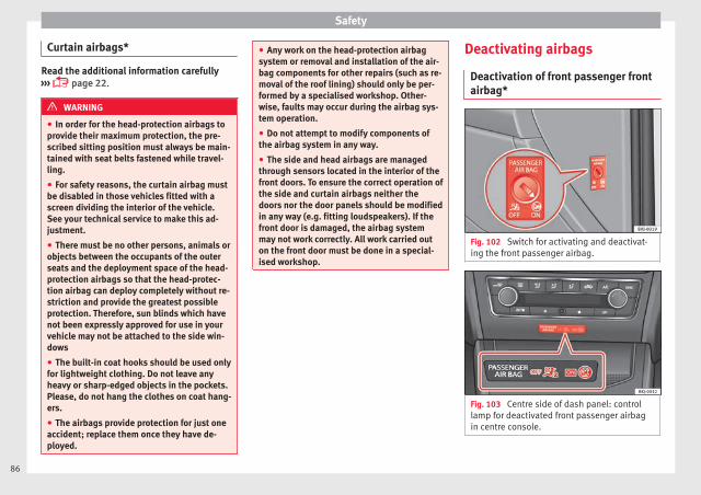
Safety
Curtain airbags*
Read the additional information carefully››› page 22.
WARNING
● In order for the head-protection airbags toprovide their maximum protection, the pre-scribed sitting position must always be main-tained with seat belts fastened while travel-ling.
● For safety reasons, the curtain airbag mustbe disabled in those vehicles fitted with ascreen dividing the interior of the vehicle.See your technical service to make this ad-justment.
● There must be no other persons, animals orobjects between the occupants of the outerseats and the deployment space of the head-protection airbags so that the head-protec-tion airbag can deploy completely without re-striction and provide the greatest possibleprotection. Therefore, sun blinds which havenot been expressly approved for use in yourvehicle may not be attached to the side win-dows
● The built-in coat hooks should be used onlyfor lightweight clothing. Do not leave anyheavy or sharp-edged objects in the pockets.Please, do not hang the clothes on coat hang-ers.
● The airbags provide protection for just oneaccident; replace them once they have de-ployed.
● Any work on the head-protection airbagsystem or removal and installation of the air-bag components for other repairs (such as re-moval of the roof lining) should only be per-formed by a specialised workshop. Other-wise, faults may occur during the airbag sys-tem operation.
● Do not attempt to modify components ofthe airbag system in any way.
● The side and head airbags are managedthrough sensors located in the interior of thefront doors. To ensure the correct operation ofthe side and curtain airbags neither thedoors nor the door panels should be modifiedin any way (e.g. fitting loudspeakers). If thefront door is damaged, the airbag systemmay not work correctly. All work carried outon the front door must be done in a special-ised workshop.
Deactivating airbags
Deactivation of front passenger frontairbag*
Fig. 102 Switch for activating and deactivat-ing the front passenger airbag.
Fig. 103 Centre side of dash panel: controllamp for deactivated front passenger airbagin centre console.
86
Airbag system
Read the additional information carefully››› page 21
If you fit a rear-facing child seat to the frontpassenger seat, the front passenger front air-bag must be de-activated.
When the front passenger airbag is deactiva-ted, this means that only the front passengerfront airbag is deactivated. All the other air-bags in the vehicle remain activated.
The and control lamps light up fora few seconds when the ignition is switchedon ››› Fig. 103. After a few seconds, only theapplicable one stays lit. If the airbag is disa-bled, stays lit permanently. If the air-bag is enabled, lights up for approxi-mately 60 seconds and then goes off.
Activating the front passenger front airbag
– Switch the ignition off.
– Open the door on the front passenger side.
– Insert the key into the slot of the switch fordeactivating the front passenger airbag››› Fig. 102. About 3/4 of the key should en-ter, as far as it will go.
– Then turn the key gently to the position.Do not force it if you feel resistance, andmake sure you have inserted the key fully.
– When the ignition is switched on, checkwhether the control lamp
on the dash panel does ››› Fig. 103not light up ››› .
– The warning lamp is illuminated for60 seconds in the centre part of the dashpanel.
WARNING
● It is the driver's responsibility to ensurethat the key-operated switch is set to the cor-rect position.
● You should deactivate the front passengerfront airbag only if you have to use a rear-fac-ing child seat in exceptional cases››› page 88, Safety for children.
● Never install a child seat facing backwardson the front passenger seat unless the frontpassenger front airbag has been disabled.Otherwise, there is a risk of death.
● As soon as the child seat is no longer nee-ded on the front passenger seat, enable thefront passenger front airbag again.
● Only deactivate the front passenger frontairbag when the ignition is off, otherwise afault may occur in the airbag system, whichcould cause the airbag to not deploy properlyor not deploy at all in case of an accident.
● Never leave the key in the airbag disablingswitch as it could get damaged or enable ordisable the airbag during driving.
● When the passenger airbag is deactivated,if the control lamp is notcontinuously lit up when the front passenger
airbag is disabled, there may be a fault in theairbag system:
– Have the airbag system inspected imme-diately by a specialised workshop.
– Do not use a child seat on the front pas-senger seat! The front passenger frontairbag could be triggered in the event ofan accident, even if there is a fault in thesystem and, as a result, a child could sus-tain serious or fatal injuries.
– It is unpredictable whether the front pas-senger airbag will deploy in the event ofan accident. Warn all your passengers ofthis.
87
Tech
nica
l dat
aA
dvic
eO
pera
tion
Emer
genc
ies
Saf
ety
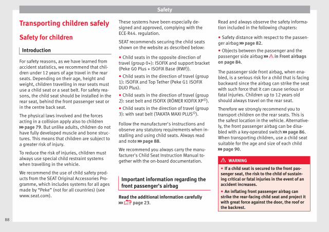
Safety
Transporting children safely
Safety for children
Introduction
For safety reasons, as we have learned fromaccident statistics, we recommend that chil-dren under 12 years of age travel in the rearseats. Depending on their age, height andweight, children travelling in rear seats mustuse a child seat or a seat belt. For safety rea-sons, the child seat should be installed in therear seat, behind the front passenger seat orin the centre back seat.
The physical laws involved and the forcesacting in a collision apply also to children››› page 79. But unlike adults, children do nothave fully developed muscle and bone struc-tures. This means that children are subject toa greater risk of injury.
To reduce the risk of injuries, children mustalways use special child restraint systemswhen travelling in the vehicle.
We recommend the use of child safety prod-ucts from the SEAT Original Accessories Pro-gramme, which includes systems for all agesmade by “Peke” (not for all countries) (seewww.seat.com).
These systems have been especially de-signed and approved, complying with theECE-R44. regulation.
SEAT recommends securing the child seatsshown on the website as described below:
● Child seats in the opposite direction oftravel (group 0+): ISOFIX and support bracket(Peke G0 Plus + ISOFIX Base (RWF)).
● Child seats in the direction of travel (group1): ISOFIX and Top Tether (Peke G1 ISOFIXDUO Plus).
● Child seats in the direction of travel (group2): seat belt and ISOFIX (RÖMER KIDFIX XP©).
● Child seats in the direction of travel (group3): with seat belt (TAKATA MAXI PLUS©).
Follow the manufacturer's instructions andobserve any statutory requirements when in-stalling and using child seats. Always readand note ››› page 88.
We recommend you always carry the manu-facturer's Child Seat Instruction Manual to-gether with the on-board documentation.
Important information regarding thefront passenger's airbag
Read the additional information carefully››› page 23.
Read and always observe the safety informa-tion included in the following chapters:
● Safety distance with respect to the passen-ger airbag ››› page 82.
● Objects between the passenger and thepassenger side airbag ››› in Front airbagson page 84.
The passenger side front airbag, when ena-bled, is a serious risk for a child that is facingbackward since the airbag can strike the seatwith such force that it can cause serious orfatal injuries. Children up to 12 years oldshould always travel on the rear seat.
Therefore we strongly recommend you totransport children on the rear seats. This isthe safest location in the vehicle. Alternative-ly, the front passenger airbag can be disa-bled with a key-operated switch ››› page 86.When transporting children, use a child seatsuitable for the age and size of each child››› page 90.
WARNING
● If a child seat is secured to the front pas-senger seat, the risk to the child of sustain-ing critical or fatal injuries in the event of anaccident increases.
● An inflating front passenger airbag canstrike the rear-facing child seat and project itwith great force against the door, the roof orthe backrest.
88
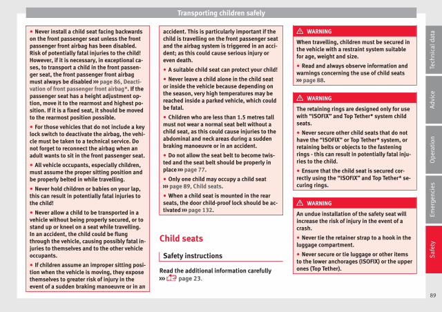
Transporting children safely
● Never install a child seat facing backwardson the front passenger seat unless the frontpassenger front airbag has been disabled.Risk of potentially fatal injuries to the child!However, if it is necessary, in exceptional ca-ses, to transport a child in the front passen-ger seat, the front passenger front airbagmust always be disabled ››› page 86, Deacti-vation of front passenger front airbag*. If thepassenger seat has a height adjustment op-tion, move it to the rearmost and highest po-sition. If it is a fixed seat, it should be movedto the rearmost position possible.
● For those vehicles that do not include a keylock switch to deactivate the airbag, the vehi-cle must be taken to a technical service. Donot forget to reconnect the airbag when anadult wants to sit in the front passenger seat.
● All vehicle occupants, especially children,must assume the proper sitting position andbe properly belted in while travelling.
● Never hold children or babies on your lap,this can result in potentially fatal injuries tothe child!
● Never allow a child to be transported in avehicle without being properly secured, or tostand up or kneel on a seat while travelling.In an accident, the child could be flungthrough the vehicle, causing possibly fatal in-juries to themselves and to the other vehicleoccupants.
● If children assume an improper sitting posi-tion when the vehicle is moving, they exposethemselves to greater risk of injury in theevent of a sudden braking manoeuvre or in an
accident. This is particularly important if thechild is travelling on the front passenger seatand the airbag system is triggered in an acci-dent; as this could cause serious injury oreven death.
● A suitable child seat can protect your child!
● Never leave a child alone in the child seator inside the vehicle because depending onthe season, very high temperatures may bereached inside a parked vehicle, which couldbe fatal.
● Children who are less than 1.5 metres tallmust not wear a normal seat belt without achild seat, as this could cause injuries to theabdominal and neck areas during a suddenbraking manoeuvre or in an accident.
● Do not allow the seat belt to become twis-ted and the seat belt should be properly inplace ››› page 77.
● Only one child may occupy a child seat››› page 89, Child seats.
● When a child seat is mounted in the rearseats, the door child-proof lock should be ac-tivated ››› page 132.
Child seats
Safety instructions
Read the additional information carefully››› page 23.
WARNING
When travelling, children must be secured inthe vehicle with a restraint system suitablefor age, weight and size.
● Read and always observe information andwarnings concerning the use of child seats››› page 88.
WARNING
The retaining rings are designed only for usewith “ISOFIX” and Top Tether* system childseats.
● Never secure other child seats that do nothave the “ISOFIX” or Top Tether* system, orretaining belts or objects to the fasteningrings - this can result in potentially fatal inju-ries to the child.
● Ensure that the child seat is secured cor-rectly using the “ISOFIX” and Top Tether* se-curing rings.
WARNING
An undue installation of the safety seat willincrease the risk of injury in the event of acrash.
● Never tie the retainer strap to a hook in theluggage compartment.
● Never secure or tie luggage or other itemsto the lower anchorages (ISOFIX) or the upperones (Top Tether).
89
Tech
nica
l dat
aA
dvic
eO
pera
tion
Emer
genc
ies
Saf
ety

Safety
Categorisation of child seats intogroups
Use only child seats that are officially ap-proved and suitable for the child.
These seats are subject to the ECE-R 44 orECE-R 129 standard. ECE-R stands for: Eco-nomic Commission for Europe Regulation.
The child seats are grouped into 5 catego-ries:
Group 0: Up to 10 kg (up to around 9months)
Group 0+: Up to 13 kg (up to around 18months)
Group 1: from 9 to 18 kg (up to approx. 4years old)
Group 2: from 15 to 25 kg (up to approx. 7years old)
Group 3: From 22 to 36 kg (over around 7years old)
Child seats that have been tested and ap-proved under the ECE-R 44 or ECE-R 129standard bear the test mark ECE-R 44 or ECE-R 129 on the seat (the letter E in a circle withthe test number below it).
Follow the manufacturer's instructions andobserve any statutory requirements when in-stalling and using child seats.
We recommend you to always include themanufacturer's Child Seat Instruction Manualtogether with the on-board documentation.
SEAT recommends you use child seats fromthe Original Accessories Catalogue. Thesechild seats have been designed and testedfor use in SEAT vehicles. You can find theright child seat for your model and age groupat SEAT dealers.
Child seats by approval category
Child seats may have the approval categoryof universal, semi-universal, vehicle specific(all according to the ECE-R 44 standard) or i-Size (according to the ECE-R 129 standard).
● Universal: Child seats with universal appro-val can be installed in all vehicles. There isno need to consult any list of models. In thecase of universal approval for ISOFIX, thechild seat is additionally provided with a TopTether belt.
● Semi-universal: semi-universal approval, inaddition to the standard requirements of uni-versal approval, requires safety devices tolock the child seat, which require additionaltesting. Child seats with semi-universal ap-proval include a list of vehicle models forwhich they can be installed.
● Vehicle-specific: vehicle-specific approvalrequires a dynamic test of the child seat foreach vehicle model separately. Child seatswith vehicle-specific approval also include a
list of vehicle models for which they can beinstalled.
● i-Size: Child seats with i-Size approval mustmeet the requirements prescribed in the ECE-R 129 standard in relation to installation andsafety. Child seat manufacturers can tell youwhich seats have i-Size approval for this vehi-cle.
Attachment systems
Depending on the country, different attach-ment systems are used for safely installingchild seats.
Attachment systems overview
● ISOFIX: ISOFIX is a standardised attach-ment system allowing quick and safe attach-ment of child seats in the vehicle. ISOFIX at-tachment establishes a rigid connection be-tween the child seat and the car body.
The child seat has two rigid attachment clips,called connectors. These connectors are fit-ted into the ISOFIX attachment rings foundbetween the seat cushion and the backrest ofthe vehicle's back seat (on the sides). ISOFIXattachment systems are used mainly in Eu-rope ››› page 26. If necessary, ISOFIX at-tachment may have to be supplemented witha Top Tether belt or a support bracket.
90

Transporting children safely
● Automatic three-point seat belt. Wheneverpossible, it is preferable to attach the childseats with the ISOFIX system rather than at-taching them with an automatic three-pointseat belt ››› page 24.
Additional attachment:
● Top Tether: The Top Tether belt is guidedover the back of the rear seat and attached toan anchor point with a hook. Anchor pointsare located at the back of the rear seat back-rest on the boot side ››› page 29. Therings for retaining the Top Tether belt aremarked with an anchor symbol.
● Support bracket: Some child seats rest onthe floor of the vehicle with a support brack-et. The support bracket prevents the childseat from tipping forward in the event of im-pact. Child seats fitted with a support bracketshould only be used in the passenger seatand side rear seats ››› . For the assembly ofthis type of seat you should also consult thelist of approved vehicles for this assembly,available in the instructions for child restraintsystems.
Recommended systems for attaching childseats
SEAT recommends attaching child seats asfollows:
● Baby carriers or child seats in the oppositedirection of travel: ISOFIX and support brack-et or iSize.
● Child seats in the direction of travel: ISO-FIX and Top Tether.
WARNING
Incorrect use of the support bracket cancause serious or fatal injury.
● Make sure the support bracket is correctlyand safely installed.
91
Tech
nica
l dat
aA
dvic
eO
pera
tion
Emer
genc
ies
Saf
ety
Safety
Event Data Recorder
Description and operation
Your vehicle has an event data recorder(EDR).
The EDR’s function is to record data in theevent of a mild or serious accident. These da-ta are used to support the analysis of howdifferent vehicle systems behaved.
The EDR records, over a reduced time range(normally 10 seconds or less), dynamic driv-ing data and data from the restraint systems,such as:
● How different vehicle systems worked.
● Whether the driver and the occupants werewearing their seatbelts.
● How hard the acceleration or brake pedalwas pressed.
● Vehicle speed.
These data will provide a better understand-ing of the circumstances of the accident.
Data from the driving assist systems are alsorecorded. This includes data such as whetherthe systems were inactive or active and ifsuch action had an impact on the vehicle’sdynamic behaviour, changing its path in theaforementioned situations, accelerating ordecelerating the vehicle.
Depending on vehicle equipment, this in-cludes data from systems such as:
● Adaptive Cruise Control (ACC)
● Front Assist.
● Park Pilot system
The EDR data are only recorded in specific ac-cident situations. No data are recorded innormal driving conditions.
No audio or video data inside or around thevehicle are recorded. Under no circumstancesare personal data such as name, age, or gen-der recorded. Nevertheless, third parties(such as criminal proceedings authorities)may relate the contents of the EDR data toother data sources and create a personal ref-erence in the context of an accident investi-gation.
In order to read the EDR data it is necessaryto access (if legally permitted to do so) thevehicle's ODB (“On-Board-Diagnose”) inter-face while the vehicle is switched on.
SEAT will not have access to EDR data unlessthe owner (or, in “Leasing” cases, the lesseeor hirer) gives their consent. There may be ex-ceptions to this, depending on legal or con-tractual provisions.
Due to legal requirements in safety-relatedproducts, SEAT may use the EDR data for fieldresearch and in order to improve vehicle sys-tem quality. Any data used for the purposes
of research will be treated anonymously (inother words, no reference will be made to thevehicle, their owner or the lessee/hirer).
92
Self-help
Emergencies
Self-help
Emergency equipment
Emergency warning triangle*
The use of reflective warning triangles isobligatory in emergencies in some countries.As are the first aid kit and a set of spare lightbulbs.
The warning triangle is under the storagecompartment which is located under the lug-gage compartment floor.
Note
● The warning triangle is not part of the vehi-cle's standard equipment.
● The warning triangle should meet legal re-quirements.
First-aid kit and fire extinguisher*
The first-aid kit can go in the storage com-partment which is located under the luggagecompartment floor.
The fire extinguisher* is attached to the lug-gage compartment carpet with Velcro.
Note
● The first-aid kit and the fire extinguisherare not part of the vehicle's standard equip-ment.
● The first aid kit must comply with legal re-quirements.
● Observe the expiry date of the contents ofthe first aid kit. After it has expired youshould purchase a new one.
● The fire extinguisher must comply with le-gal requirements.
● Ensure that the fire extinguisher is fullyfunctional. The fire extinguisher should,therefore, be checked regularly. The stickeron the fire extinguisher will inform you of thenext date for checking.
● Before acquiring accessories and emergen-cy equipment see the instructions in “Acces-sories and spares” ››› page 255.
Vehicle tools
Read the additional information carefully››› page 61
Depending on the equipment, the tools andanti-puncture kit* are stored under the floorpanel in the luggage compartment.
The tool kit includes:
● Adapter for anti-theft wheel bolts*
● Towline anchorage
● Box spanner for wheel bolts*
● Jack*
● Wire hook for pulling off the wheel cover* /wheel bolt cap clip.
Some of the items listed are only provided incertain model versions, or are optional ex-tras.
WARNING
● The factory-supplied jack is only designedfor changing wheels on this model. On no ac-count attempt to use it for lifting heavier ve-hicles or other loads. Risk of injury.
● Use the jack only on a firm, level ground.
● Never start the engine when the vehicle ison the jack. Risk of accident.
● If work is to be carried out underneath thevehicle, this must be secured by suitablemeans. Otherwise, there is a risk of injury.
Note
The jack does not generally require any main-tenance. If required, it should be greased us-ing universal type grease.
93
Tech
nica
l dat
aA
dvic
eO
pera
tion
Emer
genc
ies
Saf
ety
Emergencies
Tyre repair
TMS (Tyre Mobility System)*
Read the additional information carefully››› page 60
The Anti-puncture kit* (Tyre Mobility System)will reliably seal punctures caused by thepenetration of a foreign body of up to about4 mm in diameter. Do not remove foreign ob-jects, e.g. screws or nails, from the tyre.
After inserting the sealant residue in the tyre,you must again check the tyre pressure about10 minutes after starting the engine.
You should only use the tyre mobility set ifthe vehicle is parked in a safe place, you arefamiliar with the procedure and you have thenecessary tyre mobility set! Otherwise, youshould seek professional assistance.
Do not use the tyre sealant in the followingcases:
● If the wheel rim has been damaged.
● In outside temperatures below -20°C (-4°F).
● In the event of cuts or perforations in thetyre greater than 4 mm.
● If you have been driving with very low pres-sure or a completely flat tyre.
● If the sealant bottle has passed its use bydate.
WARNING
Using the tyre mobility system can be dan-gerous, especially when filling the tyre at theroadside. Please observe the following rulesto minimise the risk of injury:
● Stop the vehicle safely as soon as possible.Park it at a safe distance from surroundingtraffic to fill the tyre.
● Ensure the ground on which you park is flatand solid.
● All passengers and particularly childrenmust keep a safe distance from the work area.
● Turn on the hazard warning lights to warnother road users.
● Use the tyre mobility system only if you arefamiliar with the necessary procedures. Oth-erwise, you should seek professional assis-tance.
● The tyre mobility set is intended for tempo-rary emergency use only until you can reachthe nearest specialised workshop.
● Replace the repaired tyre with the tyre mo-bility set as soon as possible.
● The sealant is a health hazard and must becleaned immediately if it comes into contactwith the skin.
● Always keep the tyre mobility set out of thereach of small children.
● Never use a jack, even if it has been ap-proved for your vehicle.
● Always stop the engine, apply the hand-brake lever firmly and engage gear if using a
manual gearbox, in order to reduce the risk ofvehicle involuntary movement.
WARNING
A tyre filled with sealant does not have thesame performance properties as a conven-tional tyre.
● Never drive faster than 80 km/h (50 mph).
● Avoid heavy acceleration, hard braking andfast cornering.
● Drive for only 10 minutes at a maximumspeed of 80 km/h (50 mph) and then checkthe tyre.
For the sake of the environment
Dispose of used or expired sealant observingany legal requirements.
Note
● A new bottle of sealant can be purchased atSEAT dealerships.
● Take into account the separate instructionmanual of the tyre mobility set* manufactur-er.
94
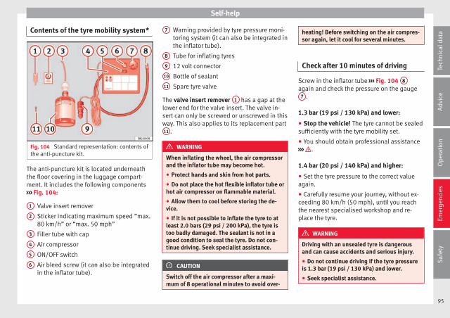
Self-help
Contents of the tyre mobility system*
Fig. 104 Standard representation: contents ofthe anti-puncture kit.
The anti-puncture kit is located underneaththe floor covering in the luggage compart-ment. It includes the following components››› Fig. 104:
Valve insert remover
Sticker indicating maximum speed “max.80 km/h” or “max. 50 mph”
Filler tube with cap
Air compressor
ON/OFF switch
Air bleed screw (it can also be integratedin the inflator tube).
1
2
3
4
5
6
Warning provided by tyre pressure moni-toring system (it can also be integrated inthe inflator tube).
Tube for inflating tyres
12 volt connector
Bottle of sealant
Spare tyre valve
The valve insert remover 1 has a gap at thelower end for the valve insert. The valve in-sert can only be screwed or unscrewed in thisway. This also applies to its replacement part11 .
WARNING
When inflating the wheel, the air compressorand the inflator tube may become hot.
● Protect hands and skin from hot parts.
● Do not place the hot flexible inflator tube orhot air compressor on flammable material.
● Allow them to cool before storing the de-vice.
● If it is not possible to inflate the tyre to atleast 2.0 bars (29 psi / 200 kPa), the tyre istoo badly damaged. The sealant is not in agood condition to seal the tyre. Do not con-tinue driving. Seek specialist assistance.
CAUTION
Switch off the air compressor after a maxi-mum of 8 operational minutes to avoid over-
7
8
9
10
11
heating! Before switching on the air compres-sor again, let it cool for several minutes.
Check after 10 minutes of driving
Screw in the inflator tube ››› Fig. 104 8
again and check the pressure on the gauge7 .
1.3 bar (19 psi / 130 kPa) and lower:
● Stop the vehicle! The tyre cannot be sealedsufficiently with the tyre mobility set.
● You should obtain professional assistance››› .
1.4 bar (20 psi / 140 kPa) and higher:
● Set the tyre pressure to the correct valueagain.
● Carefully resume your journey, without ex-ceeding 80 km/h (50 mph), until you reachthe nearest specialised workshop and re-place the tyre.
WARNING
Driving with an unsealed tyre is dangerousand can cause accidents and serious injury.
● Do not continue driving if the tyre pressureis 1.3 bar (19 psi / 130 kPa) and lower.
● Seek specialist assistance.
95
Tech
nica
l dat
aA
dvic
eO
pera
tion
Emer
genc
ies
Saf
ety
Emergencies
Changing the windscreen wiperblades
Changing the windscreen and rearwindow wiper blades
Read the additional information carefully››› page 69.
Perfect wiper blade condition is essential forclear vision. Damaged wiper blades shouldbe replaced immediately.
The windscreen wiper blades are supplied asstandard with a layer of graphite. This layer isresponsible for ensuring that the wipe is si-lent. If the graphite layer is damaged, thenoise of the water as it is wiped across thewindscreen will be louder.
Check the condition of the wiper blades regu-larly. If the wipers scrape across the glass,they should be changed if they are damaged,or cleaned if they are dirty ››› .
If this does not produce the desired results,the setting angle of the windscreen wiperarms might be incorrect. They should bechecked by a specialised workshop and cor-rected if necessary.
WARNING
Do not drive unless you have good visibilitythrough all windows!
● Clean the windscreen wiper blades and allwindows regularly.
● The wiper blades should be changed onceor twice a year.
CAUTION
● Damaged or dirty windscreen wipers couldscratch the glass.
● Never use fuel, nail varnish remover, paintthinner or similar products to clean the win-dows. This could damage the windscreenwiper blades.
● Never move any windscreen wiper by hand.This could cause damage.
● To prevent damage to the bonnet and thewindscreen wiper arms, the latter should onlybe lifted off the windscreen when in serviceposition.
Note
● The windscreen wiper arms can be movedto the service position only when the bonnetis properly closed.
● You can also use the service position, forexample, if you want to fix a cover over thewindscreen in the winter to keep it clear ofice.
Towing or tow-starting
General information
Read the additional information carefully››› page 66.
Tow-starting means starting the engine ofthe vehicle while another pulls it.
Towing means one vehicle pulling anotherthat is not roadworthy.
If the vehicle comes with the Keyless Accesssystem, towing is only allowed with the igni-tion on!
The vehicle battery drains if the vehicle istowed with the engine switched off and theignition connected. Depending on the batterycharge status, the drop in voltage may be solarge, even after just a few minutes, that noelectrical device in the vehicle may work e.g.the hazard warning lights. In vehicles withthe Keyless Access system, the steeringwheel could lock up.
WARNING
If the vehicle has no electrical power, thebrake lights, turn signals and all other lightswill no longer function. Do not have the vehi-cle towed away. Failure to follow this instruc-tion could result in an accident.
96
Self-help
WARNING
The risk of accidents is high when tow-start-ing, for example, the towed vehicle can easilybe driven into the towing vehicle.
CAUTION
If there is no oil in the gearbox or no lubricantin the automatic transmission the car mayonly be towed with the driven wheels liftedclear of the road, or transported on a specialcar transporter or trailer.
CAUTION
Do not tow a vehicle for more than 50 m in at-tempt to start it. There is risk of damage tothe catalytic converter.
Note
● Please observe related legal requirements.
● Switch on the hazard warning lights of bothvehicles. However, observe any regulationsto the contrary.
● The tow rope must not be twisted. Other-wise the front tow line anchorage could bepulled off the vehicle.
Indications for tow-starting
Vehicle's should not generally be tow-star-ted. The jump start should be used instead››› page 67.
For technical reasons, towing the followingvehicles is not allowed:
● Vehicles with an automatic gearbox.
● If the vehicle battery is discharged, be-cause in vehicles with the Keyless Accesslocking and ignition system the steering re-mains locked and the electronic parkingbrake cannot be deactivated nor can the elec-tronic lock of the steering column be re-leased if they are activated.
● If the battery is flat, it is possible that theengine control units may not operate correct-ly.
However, if the vehicle must absolutely betow-started (in the case of manual gearbox-es):
● Engage the 2nd or 3rd gear.
● Keep the clutch pressed down.
● Switch on the ignition and the hazard warn-ing lights.
● Once both vehicles are moving, release theclutch.
● Once the engine starts, press the clutchand disengage the gear to avoid collidingwith the towing vehicle.
Note
The vehicle can only be tow-started if theelectronic parking brake and, if appropriate,the electronic lock of the steering column are
deactivated. If the vehicle has no power sup-ply or there is an electric system fault, theengine must be tow-started to deactivate theelectronic parking brake and the electroniclock of the steering column.
97
Tech
nica
l dat
aA
dvic
eO
pera
tion
Emer
genc
ies
Saf
ety
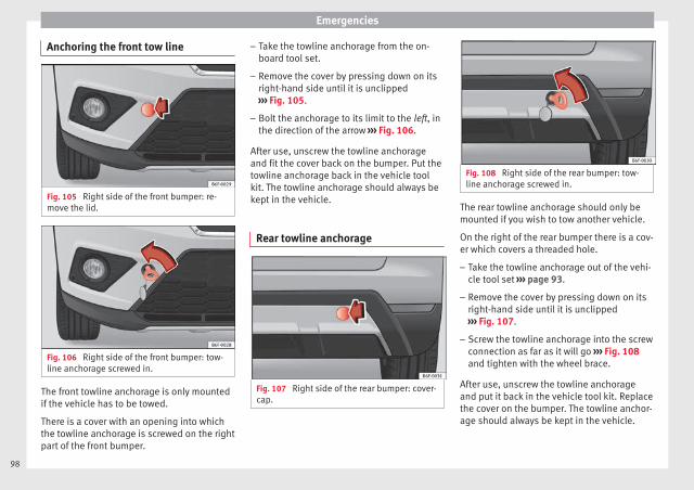
Emergencies
Anchoring the front tow line
Fig. 105 Right side of the front bumper: re-move the lid.
Fig. 106 Right side of the front bumper: tow-line anchorage screwed in.
The front towline anchorage is only mountedif the vehicle has to be towed.
There is a cover with an opening into whichthe towline anchorage is screwed on the rightpart of the front bumper.
– Take the towline anchorage from the on-board tool set.
– Remove the cover by pressing down on itsright-hand side until it is unclipped››› Fig. 105.
– Bolt the anchorage to its limit to the left, inthe direction of the arrow ››› Fig. 106.
After use, unscrew the towline anchorageand fit the cover back on the bumper. Put thetowline anchorage back in the vehicle toolkit. The towline anchorage should always bekept in the vehicle.
Rear towline anchorage
Fig. 107 Right side of the rear bumper: cover-cap.
Fig. 108 Right side of the rear bumper: tow-line anchorage screwed in.
The rear towline anchorage should only bemounted if you wish to tow another vehicle.
On the right of the rear bumper there is a cov-er which covers a threaded hole.
– Take the towline anchorage out of the vehi-cle tool set ››› page 93.
– Remove the cover by pressing down on itsright-hand side until it is unclipped››› Fig. 107.
– Screw the towline anchorage into the screwconnection as far as it will go ››› Fig. 108and tighten with the wheel brace.
After use, unscrew the towline anchorageand put it back in the vehicle tool kit. Replacethe cover on the bumper. The towline anchor-age should always be kept in the vehicle.
98

Self-help
WARNING
● If the towline anchorage is not screwed inas far as the stop, there is a risk of the screwconnection shearing off during towing (acci-dent risk).
● If your car has a towing bracket, only usespecial towing ropes. Risk of accident!
CAUTION
In vehicles fitted with a towing bracket, onlyuse special tow bars to prevent damage tothe ball joint. These tow bars have been spe-cially approved for use with towing brackets.
Towing vehicles with a manual gear-box
Towing is relatively straightforward.
Please observe the relevant instructions››› page 96.
The vehicle can be towed using a tow bar ortow rope in the normal way, with all fourwheels on the road; it can also be towed witheither the front or rear wheels lifted off theroad. The maximum towing speed is 50 km/h(30 mph).
Towing a vehicle equipped with auto-matic gearbox
Certain restrictions must be observed whentowing your vehicle.
Please observe the relevant instructions››› page 96.
The vehicle can be towed with a tow bar ortow rope in the normal way, with all fourwheels on the ground. When doing so,please note the following points:
● Make sure the selector lever is in the N po-sition.
● The vehicle must not be towed faster than50 km/h (30 mph).
● The vehicle must not be towed further than50 km (30 miles). Reason: when the engineis not running, the gearbox oil pump doesnot work and the gearbox is not adequatelylubricated for higher speeds or longer distan-ces.
If the vehicle has to be towed with a break-down truck, it must only be suspended at thefront wheels. Reason: the drive shafts are lo-cated on the front wheels. If the car is towedwith the rear wheels lifted off the road (I.e.travelling backwards), the drive shafts alsoturn backwards. The planetary gears in theautomatic gearbox then turn at such highspeeds that the gearbox will be severelydamaged in a short time.
Note
● If it is not possible to tow the vehicle in thenormal way, or if it has to be towed furtherthan 50 km (30 miles), it must be transportedon a special car transporter or trailer.
● Should the power supply to the selectorlever be interrupted in position P, the selectorlever will be locked. Before the vehicle can berecovered/manoeuvred you must manuallyrelease the selector lever.
99
Tech
nica
l dat
aA
dvic
eO
pera
tion
Emer
genc
ies
Saf
ety
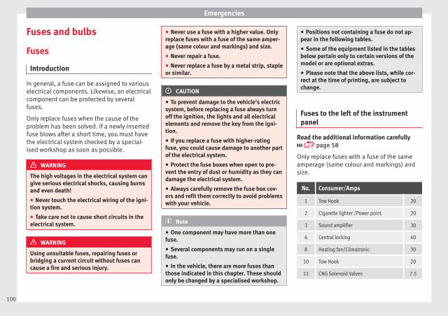
Emergencies
Fuses and bulbs
Fuses
Introduction
In general, a fuse can be assigned to variouselectrical components. Likewise, an electricalcomponent can be protected by severalfuses.
Only replace fuses when the cause of theproblem has been solved. If a newly insertedfuse blows after a short time, you must havethe electrical system checked by a special-ised workshop as soon as possible.
WARNING
The high voltages in the electrical system cangive serious electrical shocks, causing burnsand even death!
● Never touch the electrical wiring of the igni-tion system.
● Take care not to cause short circuits in theelectrical system.
WARNING
Using unsuitable fuses, repairing fuses orbridging a current circuit without fuses cancause a fire and serious injury.
● Never use a fuse with a higher value. Onlyreplace fuses with a fuse of the same amper-age (same colour and markings) and size.
● Never repair a fuse.
● Never replace a fuse by a metal strip, stapleor similar.
CAUTION
● To prevent damage to the vehicle's electricsystem, before replacing a fuse always turnoff the ignition, the lights and all electricalelements and remove the key from the igni-tion.
● If you replace a fuse with higher-ratingfuse, you could cause damage to another partof the electrical system.
● Protect the fuse boxes when open to pre-vent the entry of dust or humidity as they candamage the electrical system.
● Always carefully remove the fuse box cov-ers and refit them correctly to avoid problemswith your vehicle.
Note
● One component may have more than onefuse.
● Several components may run on a singlefuse.
● In the vehicle, there are more fuses thanthose indicated in this chapter. These shouldonly be changed by a specialised workshop.
● Positions not containing a fuse do not ap-pear in the following tables.
● Some of the equipment listed in the tablesbelow pertain only to certain versions of themodel or are optional extras.
● Please note that the above lists, while cor-rect at the time of printing, are subject tochange.
Fuses to the left of the instrumentpanel
Read the additional information carefully››› page 58
Only replace fuses with a fuse of the sameamperage (same colour and markings) andsize.
No. Consumer/Amps
1 Tow Hook 20
2 Cigarette lighter /Power point 20
3 Sound amplifier 30
6 Central locking 40
8 Heating fan/Climatronic 30
10 Tow Hook 20
11 CNG Solenoid Valves 7.5
100
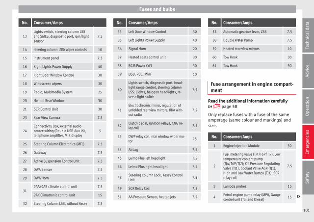
Fuses and bulbs
No. Consumer/Amps
13Lights switch, steering column LSSand SMLS, diagnostic port, rain/lightsensor
7.5
14 steering column LSS: wiper controls 10
15 Instrument panel 7.5
16 Right Lights Power Supply 40
17 Right Door Window Control 30
18 Windscreen wipers 30
19 Radio, Multimedia System 25
20 Heated Rear Window 30
21 SCR Control Unit 30
23 Rear View Camera 7.5
24Connectivity Box, external audiosource wiring (Double USB-Aux IN),telephone amplifier, MIB display
5
25 Steering Column Electronics (MFL) 7.5
26 Gateway 7.5
27 Active Suspension Control Unit 7.5
28 DWA Sensor 7.5
29 DWA Horn 7.5
319AA/9AB climate control unit 7.5
9AK Climatronic control unit 15
32 Steering Column LSS, without Kessy 7.5
No. Consumer/Amps
33 Left Door Window Control 30
35 Left Lights Power Supply 40
36 Signal Horn 20
37 Heated seats control unit 30
38 BCM Power C63 30
39 BSD, PDC, MRR 10
40
Lights switch, diagnostic port, head-light range control, steering columnLSS: Lights, halogen headlights, re-verse light switch
7.5
41Electrochromic mirror, regulation ofunfolded rear view mirrors, RKA with-out radio
7.5
42Clutch pedal, ignition relays, CNG re-lay coil
7.5
43 DWP relay coil, rear window wiper mo-tor
15
44 Airbag 7.5
45 Leimo Plus left headlight 7.5
46 Leimo Plus right headlight 7.5
48Steering Column Lock, Kessy ControlUnit
7.5
49 SCR Relay Coil 7.5
51 AA Pressure Sensor, heated jets 7.5
No. Consumer/Amps
53 Automatic gearbox lever, ZSS 7.5
58 Double Water Pump 7.5
59 Heated rear view mirrors 10
60 Tow Hook 30
61 Tow Hook 30
Fuse arrangement in engine compart-ment
Read the additional information carefully››› page 58
Only replace fuses with a fuse of the sameamperage (same colour and markings) andsize.
No. Consumer/Amps
1 Engine Injection Module 30
2
Fuel metering valve (TJ4/T6P/TJ7), Lowtemperature coolant pump(TJ4/T6P/TJ7); Oil Pressure RegulatingValve (TJ1), Coolant Valve AGR (TJ1),High and Low Water Bumps (TJ1), SCRrelay coil
7.5
3 Lambda probes 15
4Petrol engine pump relay (MPI), Gaugecontrol unit (TSI and Diesel)
15 »
101
Tech
nica
l dat
aA
dvic
eO
pera
tion
Emer
genc
ies
Saf
ety
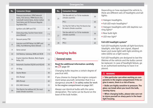
Emergencies
No. Consumer/Amps
5
Pressure transducer, EPW SolenoidValve, TOG Sensor, PWM Electric fan,Camshaft Control Valve, Active CarbonTank Valve and Oil Pressure Regulat-ing Valve (TSI)
15
6
Ignition coils (MPI and TSI) 30
Glow plug relay, Suction hose resist-ance (Diesel)
7.5
7 Vacuum pump (TSI) 15
8Injectors and EKP Relay Coil (MPI andCNG), Fuel Metering Valve (Diesel)
10
9 Servo sensor 7.5
10 Vref Battery: Gateway, BDM and BCM 7.5
14Engine Injection Module, Main EngineRelay, ESC
15
15 Automatic Gearbox DQ200 and AQ160 30
17 50 Diag 7.5
18 Starter Motor 30
20ESC (Pump) 60
ABS (Pump) 40
21 ESC/ABS (Valves) 25
24TH4 Electric fan without A/C for mod-erate climate countries
30
No. Consumer/Amps
25
TH4 fan with A/C or T5I for moderateclimate countries
20
PTC1 40
26TJ1/TJ4/TJ7/T6P or TH4/T5I Electric fanfor warm climate countries
50
27
TH4 fan with A/C or T5I for moderateclimate countries
30
PTC2 40
28 PTC3 40
Changing bulbs
General notes
Read the additional information carefully››› page 59
Changing bulbs requires a certain degree ofpractical skill.
If you choose to change the engine compart-ment lamps yourself, remember that it is adangerous area ››› in safety notes for workin the engine compartment on page 267.
Always use identical bulbs with the samedesignation. The name can be found on thebase of the bulb holder.
Depending on how equipped the vehicle is,there are different sets of headlights and taillights:
● Halogen headlights.
● Full-LED main headlights*
● Halogen headlights with LED daytime run-ning lights*
● Rear bulb light
● LED rear light*
Full-LED headlight system*
Full-LED headlights handle all light functions(daylight, side light, turn signal, dippedbeam and route light) with light emitting di-odes (LEDs) as a light source.
Full-LED headlights are designed to last thelifetime of the vehicle and the bulbs cannotbe replaced. In case of headlight failure, goto an authorised workshop to have it re-placed.
WARNING
● Take particular care when working on com-ponents in the engine compartment if the en-gine is warm, there is a risk of burns.
● Bulbs are highly sensitive to pressure. Theglass can break when you touch the bulb,causing injury.
● When changing bulbs, please take care notto injure yourself on sharp parts in the head-light housing.
102
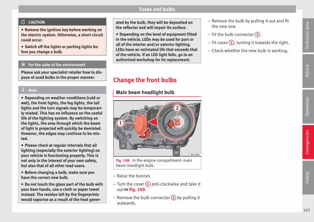
Fuses and bulbs
CAUTION
● Remove the ignition key before working onthe electric system. Otherwise, a short circuitcould occur.
● Switch off the lights or parking lights be-fore you change a bulb.
For the sake of the environment
Please ask your specialist retailer how to dis-pose of used bulbs in the proper manner.
Note
● Depending on weather conditions (cold orwet), the front lights, the fog lights, the taillights and the turn signals may be temporari-ly misted. This has no influence on the usefullife of the lighting system. By switching onthe lights, the area through which the beamof light is projected will quickly be demisted.However, the edges may continue to be mis-ted.
● Please check at regular intervals that alllighting (especially the exterior lighting) onyour vehicle is functioning properly. This isnot only in the interest of your own safety,but also that of all other road users.
● Before changing a bulb, make sure youhave the correct new bulb.
● Do not touch the glass part of the bulb withyour bare hands, use a cloth or paper towelinstead. The residue left by the fingerprintswould vaporise as a result of the heat gener-
ated by the bulb, they will be deposited onthe reflector and will impair its surface.
● Depending on the level of equipment fittedin the vehicle, LEDs may be used for part orall of the interior and/or exterior lighting.LEDs have an estimated life that exceeds thatof the vehicle. If an LED light fails, go to anauthorised workshop for its replacement.
Change the front bulbs
Main beam headlight bulb
Fig. 109 In the engine compartment: mainbeam headlight bulb.
– Raise the bonnet.
– Turn the cover 1 anti-clockwise and take itout ››› Fig. 109.
– Remove the bulb connector 2 by pulling itoutwards.
– Remove the bulb by pulling it out and fitthe new one.
– Fit the bulb connector 2 .
– Fit cover 1 , turning it towards the right.
– Check whether the new bulb is working.
103
Tech
nica
l dat
aA
dvic
eO
pera
tion
Emer
genc
ies
Saf
ety

Emergencies
Dipped beam headlight
Fig. 110 In the engine compartment: removethe lid.
Fig. 111 In the engine compartment: dippedbeam headlight.
– Raise the bonnet.
– Move the loop ››› Fig. 110 1 in the direc-tion of the arrow and remove the cover.
– Remove the bulb connector ››› Fig. 111 2 .
– Unclip the retainer spring ››› Fig. 111 3
pressing inwards to the right.
– Extract the bulb and fit the replacement sothat the lug on the base fits into the recesson the reflector.
– Fit the connector.
– Fit the cover and close the strap. Make surethat the gasket sits well on the casing coverduring the operation.
– Check whether the new bulb is working.
Turn signal light and DRL (daytimerunning light)1)
Fig. 112 In the engine compartment: turn sig-nal light bulb 1 and DRL (daytime runninglight) bulb 2 .
– Raise the bonnet.
– Turn the bulb holder ››› Fig. 112 1 or 2 tothe left and pull.
– Remove the bulb by pressing on the bulbholder and turning it anticlockwise at thesame time.
– Installation involves all of the above stepsin reverse sequence.
1) In headlight versions with LED DRL, this lightsource cannot be replaced. It is designed to last thelength of the vehicle’s service life. In case of failure,go to an authorised workshop to have it replaced.
104

Fuses and bulbs
Fog light bulb
Fig. 113 Fog light: extracting the grille
Fig. 114 Fog light: remove the bulb holder
Follow the steps indicated:
Lever the groove with a screwdriver››› Fig. 113 (arrow). Next, unclip the clipslocated on the edge of the grille, pullingon it.
Remove the 3 screws ››› Fig. 114 1 andremove the fog light.
1.
2.
Remove the bulb connector 2 .
Turn the bulb holder 3 to the left andpull.
Remove the bulb by pressing on it andturning it anticlockwise at the sametime.
Replace the bulb, making sure that thefixing guides are in the right positionand then press it and turn it clockwise.
To install the headlight go back throughthe above steps in reverse.
Check that the bulb works properly.
Change the rear bulbs
Rear bulbs (in the side panel)
Fig. 115 Luggage compartment: access to thebolt securing the tail light unit.
3.
4.
5.
6.
7
8.
Fig. 116 Retaining tabs on reverse side of taillight.
Follow the steps indicated:
Check which of the bulbs is defective.
Open the rear lid.
Remove the lid, levering the flat side ofa screwdriver into the recess››› Fig. 115 1 .
Remove the bulb connector 2 .
Unscrew the light securing bolt 3 byhand or using a screwdriver.
Remove the light from the body, gentlypulling it toward you, and place on aclean, smooth surface.
Remove the bulb holder unlocking theretaining tabs ››› Fig. 116 A .
Change the damaged bulb.
To refit follow the steps in reverse order,taking special care when fitting the bulb »
1.
2.
3.
4.
5.
6.
7.
8.
9.
105
Tech
nica
l dat
aA
dvic
eO
pera
tion
Emer
genc
ies
Saf
ety
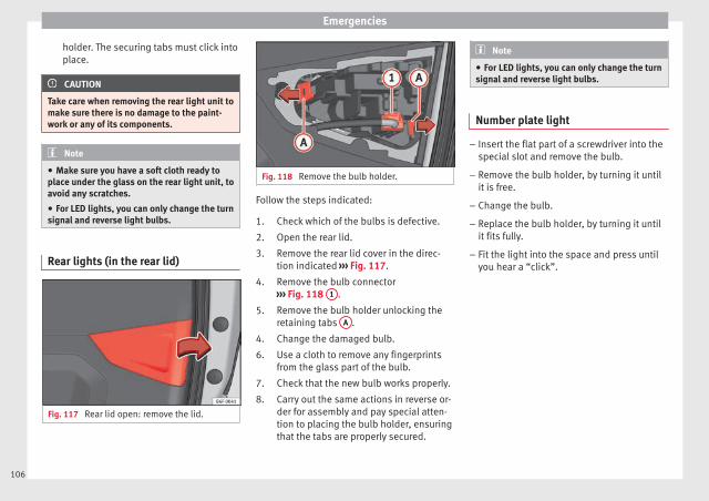
Emergencies
holder. The securing tabs must click intoplace.
CAUTION
Take care when removing the rear light unit tomake sure there is no damage to the paint-work or any of its components.
Note
● Make sure you have a soft cloth ready toplace under the glass on the rear light unit, toavoid any scratches.
● For LED lights, you can only change the turnsignal and reverse light bulbs.
Rear lights (in the rear lid)
Fig. 117 Rear lid open: remove the lid.
Fig. 118 Remove the bulb holder.
Follow the steps indicated:
Check which of the bulbs is defective.
Open the rear lid.
Remove the rear lid cover in the direc-tion indicated ››› Fig. 117.
Remove the bulb connector››› Fig. 118 1 .
Remove the bulb holder unlocking theretaining tabs A .
Change the damaged bulb.
Use a cloth to remove any fingerprintsfrom the glass part of the bulb.
Check that the new bulb works properly.
Carry out the same actions in reverse or-der for assembly and pay special atten-tion to placing the bulb holder, ensuringthat the tabs are properly secured.
1.
2.
3.
4.
5.
4.
6.
7.
8.
Note
● For LED lights, you can only change the turnsignal and reverse light bulbs.
Number plate light
– Insert the flat part of a screwdriver into thespecial slot and remove the bulb.
– Remove the bulb holder, by turning it untilit is free.
– Change the bulb.
– Replace the bulb holder, by turning it untilit fits fully.
– Fit the light into the space and press untilyou hear a “click”.
106

Fuses and bulbs
Side turn signals
Fig. 119 Turn signal integrated in the rearview mirror
The side turn signals are LEDS and are inte-grated in the rear view mirrors.
In case of failure, go to an authorised work-shop to have it replaced.
Additional brake light
Given the difficulty involved in the replace-ment of this light it should be done by Tech-nical Services.
Changing the interior bulbs
Interior light and front reading lights
Fig. 120 Front reading light.
To remove the glass
– Insert a fine screwdriver between the cas-ing and the glass ››› Fig. 120.
– Carefully remove the glass, levering it toavoid possible damage.
To replace the bulbs
– Pull the bulbs outwards.
– To remove the central bulb, hold and pressto one side.
Assembly
– Proceed in the reverse order, pressing gen-tly on the outer edge of the side light.
– First fit the glass with the fastening tabsover the frame of the switch. Next press thefront part until the two long tabs click onthe support.
Note
In LED courtesy lights it is not possible to re-place the light sources. If the light does notwork, take the vehicle to an official Service.
107
Tech
nica
l dat
aA
dvic
eO
pera
tion
Emer
genc
ies
Saf
ety

Emergencies
Luggage compartment light*
Fig. 121 Boot light.
Fig. 122 Boot light.
– Extract the bulb by pressing on its insideedge -arrow- using the flat side of a screw-driver ››› Fig. 121.
– Press the bulb sideways and remove it fromits housing ››› Fig. 122.
108

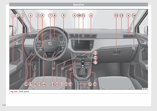
Operation
Fig. 123 Dash panel.
110
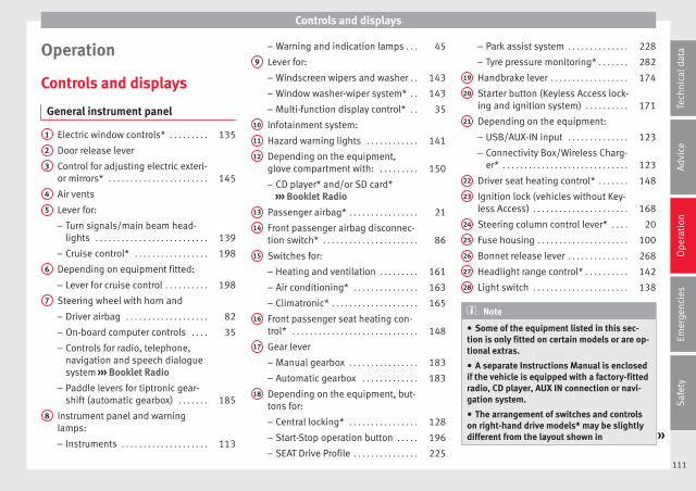
Controls and displays
Operation
Controls and displays
General instrument panel
Electric window controls* . . . . . . . . . 135
Door release lever
Control for adjusting electric exteri-or mirrors* . . . . . . . . . . . . . . . . . . . . . . . 145
Air vents
Lever for:
– Turn signals/main beam head-lights . . . . . . . . . . . . . . . . . . . . . . . . . . 139
– Cruise control* . . . . . . . . . . . . . . . . . 198
Depending on equipment fitted:
– Lever for cruise control . . . . . . . . . . 198
Steering wheel with horn and
– Driver airbag . . . . . . . . . . . . . . . . . . . 82
– On-board computer controls . . . . 35
– Controls for radio, telephone,navigation and speech dialoguesystem ››› Booklet Radio
– Paddle levers for tiptronic gear-shift (automatic gearbox) . . . . . . . 185
Instrument panel and warninglamps:
– Instruments . . . . . . . . . . . . . . . . . . . . 113
1
2
3
4
5
6
7
8
– Warning and indication lamps . . . 45
Lever for:
– Windscreen wipers and washer . . 143
– Window washer-wiper system* . . 143
– Multi-function display control* . . 35
Infotainment system:
Hazard warning lights . . . . . . . . . . . . 141
Depending on the equipment,glove compartment with: . . . . . . . . . 150
– CD player* and/or SD card*››› Booklet Radio
Passenger airbag* . . . . . . . . . . . . . . . . 21
Front passenger airbag disconnec-tion switch* . . . . . . . . . . . . . . . . . . . . . . 86
Switches for:
– Heating and ventilation . . . . . . . . . 161
– Air conditioning* . . . . . . . . . . . . . . . 163
– Climatronic* . . . . . . . . . . . . . . . . . . . . 165
Front passenger seat heating con-trol* . . . . . . . . . . . . . . . . . . . . . . . . . . . . . 148
Gear lever
– Manual gearbox . . . . . . . . . . . . . . . . 183
– Automatic gearbox . . . . . . . . . . . . . 183
Depending on the equipment, but-tons for:
– Central locking* . . . . . . . . . . . . . . . . 128
– Start-Stop operation button . . . . . 196
– SEAT Drive Profile . . . . . . . . . . . . . . . 225
9
10
11
12
13
14
15
16
17
18
– Park assist system . . . . . . . . . . . . . . 228
– Tyre pressure monitoring* . . . . . . . 282
Handbrake lever . . . . . . . . . . . . . . . . . . 174
Starter button (Keyless Access lock-ing and ignition system) . . . . . . . . . . 171
Depending on the equipment:
– USB/AUX-IN input . . . . . . . . . . . . . . 123
– Connectivity Box/Wireless Charg-er* . . . . . . . . . . . . . . . . . . . . . . . . . . . . . 123
Driver seat heating control* . . . . . . . 148
Ignition lock (vehicles without Key-less Access) . . . . . . . . . . . . . . . . . . . . . . 168
Steering column control lever* . . . . 20
Fuse housing . . . . . . . . . . . . . . . . . . . . . 100
Bonnet release lever . . . . . . . . . . . . . . 268
Headlight range control* . . . . . . . . . . 142
Light switch . . . . . . . . . . . . . . . . . . . . . . 138
Note
● Some of the equipment listed in this sec-tion is only fitted on certain models or are op-tional extras.
● A separate Instructions Manual is enclosedif the vehicle is equipped with a factory-fittedradio, CD player, AUX IN connection or navi-gation system.
● The arrangement of switches and controlson right-hand drive models* may be slightlydifferent from the layout shown in »
19
20
21
22
23
24
25
26
27
28
111
Tech
nica
l dat
aA
dvic
eO
pera
tion
Emer
genc
ies
Saf
ety
Operation
››› page 111. However, the symbols used toidentify the controls are the same.
112
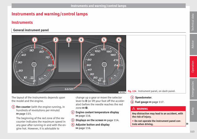
Instruments and warning/control lamps
Instruments and warning/control lamps
Instruments
General instrument panel
Fig. 124 Instrument panel, on dash panel.
The layout of the instruments depends uponthe model and the engine.
Rev counter (with the engine running, inhundreds of revolutions per minute)››› page 115.
The beginning of the red zone of the revcounter indicates the maximum speed inany gear after running-in and with the en-gine hot. However, it is advisable to
1
change up a gear or move the selectorlever to D (or lift your foot off the acceler-ator) before the needle reaches the redzone ››› .
Engine coolant temperature display››› page 116.
Displays on the screen ››› page 114.
Adjuster button and display››› page 116.
2
3
4
Speedometer.
Fuel gauge ››› page 117.
WARNING
Any distraction may lead to an accident, withthe risk of injury.
● Do not operate the instrument panel con-trols when driving. »
5
6
113
Tech
nica
l dat
aA
dvic
eO
pera
tion
Emer
genc
ies
Saf
ety

Operation
CAUTION
● When the engine is cold, avoid high revsand heavy acceleration and do not make theengine work hard.
Indications on the display
A variety of information can be viewed on theinstrument panel display ››› Fig. 124 3 de-pending on the vehicle equipment:
● Bonnet, rear lid and doors open››› page 38.
● Information and warning texts.
● Mileage.
● Time.
● Navigation instructions.
● Outside temperature.
● Compass.
● Shift lever position ››› page 183.
● Recommended gear (manual gearbox)››› page 39.
● Multifunction display (MFD) and menuswith different setting options ››› page 35.
● Service interval display ››› page 41.
● Second speed display ››› page 35.
● Speed warning function ››› page 40.
● Start-Stop system status display››› page 196.
● Identifying letters on engine (MKB).
Distance travelled
The odometer registers the total distancetravelled by the car.
The odometer (trip) shows the distancetravelled since the last odometer reset. Thelast digit of the trip recorder indicates distan-ces of 100 metres or one tenths of a mile.
● Briefly press the button ››› Fig. 124 4 to re-set the trip recorder to 0.
● Keep the button 4 pressed for about 3seconds and the previous value will be dis-played.
Time
● To set the time, keep the button ››› Fig. 1244 pressed for more than 3 seconds to select
the hour or minute display.
● To continue setting the time, press button4 . Hold button down to scroll through the
numbers quickly.
● Press the button 4 again in order to finishsetting the time.
The time can also be set via the buttonand the SETTINGS function button in the EasyConnect system ››› page 118.
Compass
With the ignition on and the navigation sys-tem on, the cardinal point corresponding tothe direction of travel of the vehicle is dis-played on the instrument panel.
Selector lever position
The selected gear is displayed on the side ofthe selector lever and on the instrument pan-el display. In positions D and S, and with theTiptronic, the corresponding gear is also dis-played.
Recommended gear (manual gearbox)
The recommended gear in order to save fuelis displayed on the instrument panel whileyou are driving ››› page 39.
Second speed display (mph or km/h)
In addition to the speedometer, the speedcan also be displayed in a different unit ofmeasurement (in miles or in km per hour).
This option cannot be deactivated in modelsdestined for countries in which the secondspeed must always be visible.
The second speed display can be adjusted inthe Easy Connect system via the buttonand the SETTINGS function button››› page 118.
114

Instruments and warning/control lamps
Speed warning
When the speed setting is exceeded, this willbe indicated on the instrument panel display.This is very useful, for example when usingwinter tyres that are not designed for drivingat the maximum speed of the vehicle››› page 40.
The speed warning settings can be adjustedin the Easy Connect system via the buttonand the SETTINGS function button››› page 118.
Start-Stop operating display
Updated information relating to the status isdisplayed on the instrument panel››› page 196.
Identifying letters on engine (MKB)
Hold the button ››› Fig. 124 4 down for morethan 15 seconds to display the identifyingletters of the vehicle engine (MKB). To dothis, the ignition must be switched on andthe engine switched off.
WARNING
Observe the safety warnings ››› in Warningsymbols on page 117.
WARNING
Even though outside temperatures are abovefreezing, some roads and bridges may be icy.
● At outside temperatures above +4°C(+39°F), even when the “ice crystal symbol”is not visible, there may still be patches of iceon the road.
● Do not rely on the outside temperature in-dicator!
Note
● Different versions of the instrument panelare available and therefore the versions andinstructions on the display may vary. In thecase of displays without warning or informa-tion texts, faults are indicated exclusively bythe warning lamps.
● Depending on the equipment, some set-tings and instructions can also be carried outin the Easy Connect system.
● When several warnings are active at thesame time, the symbols are shown succes-sively for a few seconds and will stay on untilthe fault is rectified.
Rev counter
The rev counter indicates the number of en-gine revolutions per minute ››› Fig. 124 1 .
Together with the gear-change indicator, therev counter offers you the possibility of usingthe engine of your vehicle at a suitablespeed.
The start of the red zone on the dial indicatesthe maximum engine speed which may beused briefly when the engine is warm and af-ter it has been run in properly. Before reach-ing this range, you should change to a highergear for vehicles with a manual gearbox or forautomatic gearboxes put the selector lever in“D” or take your foot off the accelerator ped-al.
We recommend that you avoid high revs andthat you follow the recommendations on thegear-change indicator. Consult the additionalinformation in ››› page 39, Gear-changeindicator.
CAUTION
Never allow the rev counter needle 1
››› Fig. 124 to go into the red zone on thescale for more than a very brief period, other-wise there is a risk of engine damage.
For the sake of the environment
Changing up a gear early will help you to savefuel and minimise emissions and enginenoise.
115
Tech
nica
l dat
aA
dvic
eO
pera
tion
Emer
genc
ies
Saf
ety

Operation
Odometer
Fig. 125 Instrument panel: odometer and re-set button.
The distance covered is displayed in “kilome-tres” or miles “m”. It is possible to changethe measurement units (kilometres“km”/miles “m”) in the radio/Easy Connect*.Please refer to the Easy Connect* InstructionsManual for more details.
Odometer/trip recorder
The odometer shows the total distance cov-ered by the vehicle.
The trip recorder shows the distance that hasbeen travelled since it was last reset. It isused to measure short trips. The last digit ofthe trip recorder indicates distances of 100metres or tenths of a mile.
The trip recorder can be set to zero by press-ing 0.0/SET ››› Fig. 125.
Fault display
If there is a fault in the instrument panel, theletters DEF will appear in the trip recorderdisplay. Have the fault repaired immediately,as far as is possible.
Coolant temperature gauge
For vehicles with no coolant temperaturegauge, a control lamp appears for highcoolant temperatures ››› page 273. Pleasenote ››› .
The coolant temperature gauge 2
››› Fig. 124 only works when the ignition isswitched on. In order to avoid engine dam-age, please read the following notes for thedifferent temperature ranges.
Engine cold
If only the diodes in the lower part of thescale light up, this indicates that the enginehas not yet reached operating temperature.Avoid high revs and heavy acceleration anddo not make the engine work hard.
Normal temperature
If in normal operations, the diodes light upuntil the central zone, it means that the en-gine has reached operating temperature. Athigh outside temperatures and when makingthe engine work hard, the diodes may contin-
ue lighting up and reach the upper zone. Thisis no cause for concern, provided the controllamp does not light up on the instrumentpanel digital display.
Heat range
When the diodes light up in the upper area ofthe display and the control lamp appears on the instrument panel display, the coolanttemperature is excessive ››› page 273.
CAUTION
● To ensure a long useful life for the engine,avoid high revs, driving at high speed andmaking the engine work hard for approxi-mately the first 15 minutes when the engineis cold. The phase until the engine is warm al-so depends on the outside temperature. Ifnecessary, use the engine oil temperature*››› page 40 as a guide.
● Additional lights and other accessories infront of the air inlet reduce the cooling effectof the coolant. At high outside temperaturesand high engine loads, there is a risk of theengine overheating.
● The front spoiler also ensures proper distri-bution of the cooling air when the vehicle ismoving. If the spoiler is damaged this can re-duce the cooling effect, which could causethe engine to overheat. Seek specialist assis-tance.
116
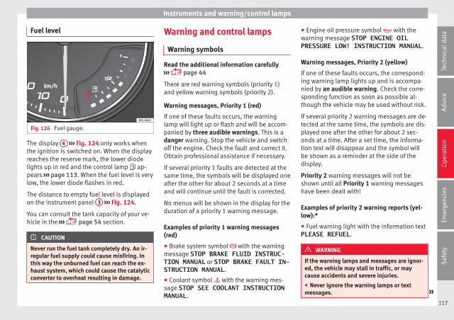
Instruments and warning/control lamps
Fuel level
Fig. 126 Fuel gauge.
The display 6 ››› Fig. 124 only works whenthe ignition is switched on. When the displayreaches the reserve mark, the lower diodelights up in red and the control lamp ap-pears ››› page 113. When the fuel level is verylow, the lower diode flashes in red.
The distance to empty fuel level is displayedon the instrument panel 3 ››› Fig. 124.
You can consult the tank capacity of your ve-hicle in the ››› page 54 section.
CAUTION
Never run the fuel tank completely dry. An ir-regular fuel supply could cause misfiring. Inthis way the unburned fuel can reach the ex-haust system, which could cause the catalyticconverter to overheat resulting in damage.
Warning and control lamps
Warning symbols
Read the additional information carefully››› page 44
There are red warning symbols (priority 1)and yellow warning symbols (priority 2).
Warning messages, Priority 1 (red)
If one of these faults occurs, the warninglamp will light up or flash and will be accom-panied by three audible warnings. This is adanger warning. Stop the vehicle and switchoff the engine. Check the fault and correct it.Obtain professional assistance if necessary.
If several priority 1 faults are detected at thesame time, the symbols will be displayed oneafter the other for about 2 seconds at a timeand will continue until the fault is corrected.
No menus will be shown in the display for theduration of a priority 1 warning message.
Examples of priority 1 warning messages(red)
● Brake system symbol with the warningmessage STOP BRAKE FLUID INSTRUC-TION MANUAL or STOP BRAKE FAULT IN-STRUCTION MANUAL.
● Coolant symbol with the warning mes-sage STOP SEE COOLANT INSTRUCTIONMANUAL.
● Engine oil pressure symbol with thewarning message STOP ENGINE OILPRESSURE LOW! INSTRUCTION MANUAL.
Warning messages, Priority 2 (yellow)
If one of these faults occurs, the correspond-ing warning lamp lights up and is accompa-nied by an audible warning. Check the corre-sponding function as soon as possible al-though the vehicle may be used without risk.
If several priority 2 warning messages are de-tected at the same time, the symbols are dis-played one after the other for about 2 sec-onds at a time. After a set time, the informa-tion text will disappear and the symbol willbe shown as a reminder at the side of thedisplay.
Priority 2 warning messages will not beshown until all Priority 1 warning messageshave been dealt with!
Examples of priority 2 warning reports (yel-low):*
● Fuel warning light with the information textPLEASE REFUEL.
WARNING
If the warning lamps and messages are ignor-ed, the vehicle may stall in traffic, or maycause accidents and severe injuries.
● Never ignore the warning lamps or textmessages. »
117
Tech
nica
l dat
aA
dvic
eO
pera
tion
Emer
genc
ies
Saf
ety
Operation
● Stop the vehicle safely as soon as possible.
● Park the vehicle away from traffic and en-sure that there are no highly flammable ma-terials under the vehicle that could come intocontact with the exhaust system (e.g. drygrass, fuel).
● A faulty vehicle represents a risk of acci-dent for the driver and for other road users. Ifnecessary, switch on the hazard warninglamps and put out the warning triangle to ad-vise other drivers.
● Before opening the bonnet, switch off theengine and allow it to cool.
● In any vehicle, the engine compartment is ahazardous area and could cause severe inju-ries ››› page 267.
CAUTION
Failure to heed the control lamps and textmessages when they appear may result infaults in the vehicle.
Introduction to the EasyConnect system*
System settings (CAR)*
CAR menu
Read the additional information carefully››› page 33
To select the settings menus, depending onthe version, press the Easy Connect button and the SETTINGS function button, OR
press the button and then SETTINGS .
The actual number of menus available andthe name of the various options in these me-nus will depend on the vehicle’s electronicsand equipment.
Pressing the menu button will always takeyou to the last menu used.
When the function button check box is activa-ted , the function is active.
Pressing the menu button will always takeyou to the last menu used.
Any changes made using the settings menusare automatically saved on closing those me-nus.
Function buttons in thevehicle settingsmenu
Page
ESC system ››› page 177
Tyres ››› page 282
Driver assistance ››› table on page 33
Parking and manoeuvring ››› page 236
Vehicle lights ››› table on page 33
Mirrors and windscreen wipers ››› table on page 33
Opening and closing ››› table on page 33
Multifunction display ››› table on page 33
Date and time ››› table on page 33
Units ››› table on page 33
Service ››› page 114
Factory settings ››› table on page 33
WARNING
Any distraction may lead to an accident, withthe risk of injury. Operating the Easy Connectsystem while driving could distract you fromtraffic.
118
Communications and multimedia
Communications and multi-media
Steering wheel controls*
General information
The steering wheel includes a multifunctionmodule from where it is possible to controlthe audio, telephone and radio/navigationfunctions without needing to distract thedriver.
There are two versions of the multifunctionmodule:
● Audio system + telephone without voicecontrol version (MID): for controlling the au-dio functions available (radio, audio CD,MP3, iPod®1), USB1), SD1)) and Bluetooth sys-tem from the steering wheel.
● Audio system + telephone with voice con-trol version (HIGH): for controlling the audiofunctions available (radio, audio CD, MP3,iPod®1), USB1), SD1)) and Bluetooth systemfrom the steering wheel.
1) Depending on the vehicle equipment.119
Tech
nica
l dat
aA
dvic
eO
pera
tion
Emer
genc
ies
Saf
ety

Operation
Operating the telephone and audio system without voice control (MID)
Fig. 127 Controls on the steering wheel.
Button Radio Media (except AUX) AUX Telephone Navigation*
ATurn: Turn volume up/down
Press: MuteTurn: Turn volume up/down
Press: MuteTurn: Turn volume up/down
Press: MuteTurn: Turn volume up/down
Press: MuteTurn: Turn volume up/down
Press: Mute
BShort press: access to the tele-phone menu in the instrument
panela).
Short press: access to the tele-phone menu in the instrument
panela).
Short press: access to the tele-phone menu in the instrument
panela).
Short press: answer incomingcall / hang up call / access to
the call list.Hold down: reject incoming
call / rediala).
Short press: access to the tele-phone menu in the instrument
panela).
C Search for last stationShort press: switch to the pre-
vious songHold down: quick rewind
No function No function No function
D Search for the next stationShort press: switch to the next
songHold down: fast forward
No function No function No function
E , FChange menu on instrument
panela)Change menu on instrument
panela)Change menu on instrument
panela)Change menu on instrument
panela)Change menu on instrument
panela)
G MID: change source MID: change source MID: change source MID: change source MID: change source
120
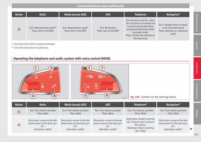
Communications and multimedia
Button Radio Media (except AUX) AUX Telephone Navigation*
HTurn: Next/previous presetb)
Press: Acts on the MFDTurn: Next/previous songb)
Press: Acts on the MFDTurn: No function
Press: Acts on the MFD
Turn: Access to call list / selec-tion of action on incoming call
or active call (answer/hang-up/ignore/hold/mute/switch
to private mode).Press: Confirm the selected ac-
tion by turning.
Turn: Changes menu or memo-ry on instrument panel
Press: Operates on instrumentpanel
a) According to the vehicle's equipment package.b) Only if the dash panel is in audio menu.
Operating the telephone and audio system with voice control (HIGH)
Fig. 128 Controls on the steering wheel.
Button Radio Media (except AUX) AUX Telephonea) Navigationa)
ATurn: Turn volume up/down
Press: MuteTurn: Turn volume up/down
Press: MuteTurn: Turn volume up/down
Press: MuteTurn: Turn volume up/down
Press: MuteTurn: Turn volume up/down
Press: Mute
B
Short press: access to the tele-phone menu on the dash pan-
ela).Hold down: rediala)
Short press: access to the tele-phone menu on the dash pan-
ela).Hold down: rediala)
Short press: access to the tele-phone menu on the dash pan-
ela).Hold down: rediala)
Short press: Answer incomingcall / hang up call / access to
the call list.Hold down: Reject incoming
call / redial
Short press: access to the tele-phone menu on the dash pan-
ela).Hold down: rediala) »
121
Tech
nica
l dat
aA
dvic
eO
pera
tion
Emer
genc
ies
Saf
ety
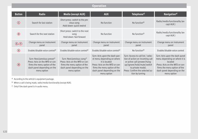
Operation
Button Radio Media (except AUX) AUX Telephonea) Navigationa)
C Search for last stationShort press: switch to the pre-
vious songHold down: quick rewind
No function No functionb) Radio/media functionality (ex-cept AUX )
D Search for the next stationShort press: switch to the next
songHold down: fast forward
No function No functionb) Radio/media functionality (ex-cept AUX )
E , FChange menu on instrument
panelChange menu on instrument
panelChange menu on instrument
panelChange menu on instrument
panelChange menu on instrument
panel
G Enable/disable voice controla) Enable/disable voice controla) Enable/disable voice controla) No functionb) Enable/disable voice control
H
Turn: Next/previous presetc)
Press: Acts on the MFD or con-firms the menu option of thedash panel depending on the
menu option
Turn: Next/previous songc)
Press: Acts on the MFD or con-firms the menu option of thedash panel depending on the
menu option
Turn: Acts upon the dash pan-el menu depending on where
it is locatedPress: Acts on the MFD or con-firms the menu option of thedash panel depending on the
menu option
Turn: Access to call list / selec-tion of action on incoming call
or active call (answer/hang-up/ignore/hold/mute/switch
to private mode).Press: Confirm the selected ac-
tion by turning
Turn: Acts upon the dash panelmenu depending on where it is
locatedPress: Acts on the MFD or con-firms the menu option of thedash panel depending on the
menu option
a) According to the vehicle's equipment package.b) When a call is being made, radio/media functionality (except AUX).c) Only if the dash panel is in audio menu.
122
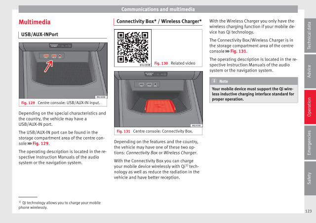
Communications and multimedia
Multimedia
USB/AUX-INPort
Fig. 129 Centre console: USB/AUX-IN input.
Depending on the special characteristics andthe country, the vehicle may have aUSB/AUX-IN port.
The USB/AUX-IN port can be found in thestorage compartment area of the centre con-sole ››› Fig. 129.
The operating description is located in the re-spective Instruction Manuals of the audiosystem or the navigation system.
Connectivity Box* / Wireless Charger*
Fig. 130 Related video
Fig. 131 Centre console: Connectivity Box.
Depending on the features and the country,the vehicle may have one of these two op-tions: Connectivity Box or Wireless Charger.
With the Connectivity Box you can chargeyour mobile device wirelessly with Qi1) tech-nology as well as reduce the radiation in thevehicle and have better reception.
With the Wireless Charger you only have thewireless charging function if your mobile de-vice has Qi technology.
The Connectivity Box/Wireless Charger is inthe storage compartment area of the centreconsole ››› Fig. 131.
The operating description is located in the re-spective Instruction Manuals of the audiosystem or the navigation system.
Note
Your mobile device must support the Qi wire-less inductive charging interface standard forproper operation.
1) Qi technology allows you to charge your mobilephone wirelessly.
123
Tech
nica
l dat
aA
dvic
eO
pera
tion
Emer
genc
ies
Saf
ety
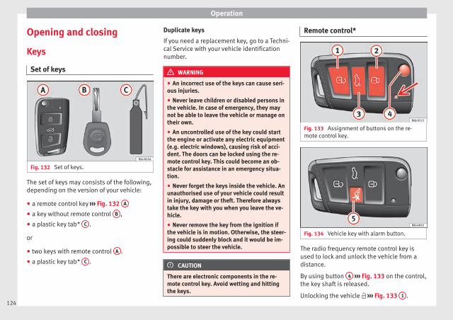
Operation
Opening and closing
Keys
Set of keys
Fig. 132 Set of keys.
The set of keys may consists of the following,depending on the version of your vehicle:
● a remote control key ››› Fig. 132 A
● a key without remote control B ,
● a plastic key tab* C .
or
● two keys with remote control A .
● a plastic key tab* C .
Duplicate keys
If you need a replacement key, go to a Techni-cal Service with your vehicle identificationnumber.
WARNING
● An incorrect use of the keys can cause seri-ous injuries.
● Never leave children or disabled persons inthe vehicle. In case of emergency, they maynot be able to leave the vehicle or manage ontheir own.
● An uncontrolled use of the key could startthe engine or activate any electric equipment(e.g. electric windows), causing risk of acci-dent. The doors can be locked using the re-mote control key. This could become an ob-stacle for assistance in an emergency situa-tion.
● Never forget the keys inside the vehicle. Anunauthorised use of your vehicle could resultin injury, damage or theft. Therefore alwaystake the key with you when you leave the ve-hicle.
● Never remove the key from the ignition ifthe vehicle is in motion. Otherwise, the steer-ing could suddenly block and it would be im-possible to steer the vehicle.
CAUTION
There are electronic components in the re-mote control key. Avoid wetting and hittingthe keys.
Remote control*
Fig. 133 Assignment of buttons on the re-mote control key.
Fig. 134 Vehicle key with alarm button.
The radio frequency remote control key isused to lock and unlock the vehicle from adistance.
By using button 4 ››› Fig. 133 on the control,the key shaft is released.
Unlocking the vehicle ››› Fig. 133 1 .124

Opening and closing
Locking the vehicle ››› Fig. 133 2 .
Unlocking the rear lid. Press button ››› Fig. 133 3 until all the turn signals on thevehicle flash briefly. When the unlocking but-ton 3 is pressed, you have 2 minutes toopen the door. Once this time has passed, itwill lock again.
Moreover, the battery indicator on the key››› Fig. 133 (arrow), will flash.
The remote control transmitter and the bat-teries are integrated in the key. The receiveris inside the vehicle. The maximum range de-pends on different factors. The range is re-duced as the batteries start to lose power.
Alarm button*
Only press alarm button in the event of anemergency ››› Fig. 134 5 ! When the alarmbutton is pressed, the vehicle horn is heardand the turn signals are switched on for ashort time. When the alarm button is pressedagain, the alarm is switched off.
WARNING
Read and observe the relevant warnings ››› in Set of keys on page 124.
Note
● The remote control key works only whenyou are in its scope.
● If the vehicle cannot be unlocked or lockedby using the radio frequency remote control,the remote control key will have to be re-synchronised. For this, go to your technicalservices.
Replacing the battery
Fig. 135 Vehicle key: opening the batterycompartment.
Fig. 136 Vehicle key: removing the battery.
SEAT recommends you ask a specialisedworkshop to replace the battery.
The battery is located to the rear of the vehi-cle key, under a cover.
Changing the battery
● Unfold the vehicle key blade ››› page 124.
● Remove the cover from the back of the ve-hicle key ››› Fig. 135 in the direction of the ar-row ››› .
● Extract the battery from the compartmentusing a suitable thin object ››› Fig. 136.
● Place the new battery in the compartmentas shown ››› Fig. 136, pressing in the oppo-site direction to that shown by the arrow››› .
● Fit the cover as shown ››› Fig. 135, pressingit onto the vehicle key casing in the oppositedirection to that shown by the arrow until itclicks into place.
CAUTION
● If the battery is not changed correctly, thevehicle key may be damaged.
● Use of unsuitable batteries may damagethe vehicle key. For this reason, always re-place the dead battery with another of thesame voltage, size and specifications.
● When fitting the battery, check that the po-larity is correct. »
125
Tech
nica
l dat
aA
dvic
eO
pera
tion
Emer
genc
ies
Saf
ety
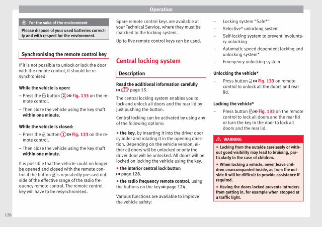
Operation
For the sake of the environment
Please dispose of your used batteries correct-ly and with respect for the environment.
Synchronising the remote control key
If it is not possible to unlock or lock the doorwith the remote control, it should be re-synchronised.
While the vehicle is open:
– Press the button 2 ››› Fig. 133 on the re-mote control.
– Then close the vehicle using the key shaftwithin one minute.
While the vehicle is closed:
– Press the button 1 ››› Fig. 133 on the re-mote control.
– Then close the vehicle using the key shaftwithin one minute.
It is possible that the vehicle could no longerbe opened and closed with the remote con-trol if the button is repeatedly pressed out-side of the effective range of the radio fre-quency remote control. The remote controlkey will have to be resynchronised.
Spare remote control keys are available atyour Technical Service, where they must bematched to the locking system.
Up to five remote control keys can be used.
Central locking system
Description
Read the additional information carefully››› page 15.
The central locking system enables you tolock and unlock all doors and the rear lid byjust pushing the button.
Central locking can be activated by using anyof the following options:
● the key, by inserting it into the driver doorcylinder and rotating it in the opening direc-tion. Depending on the vehicle version, ei-ther all doors will be unlocked or only thedriver door will be unlocked. All doors will belocked on locking the vehicle using the key.
● the interior central lock button››› page 128.
● the radio frequency remote control, usingthe buttons on the key ››› page 124.
Various functions are available to improvethe vehicle safety:
Locking system “Safe*”
Selective* unlocking system
Self-locking system to prevent involunta-ry unlocking
Automatic speed dependent locking andunlocking system*
Emergency unlocking system
Unlocking the vehicle*
Press button ››› Fig. 133 on remotecontrol to unlock all the doors and rearlid.
Locking the vehicle*
Press button ››› Fig. 133 on the remotecontrol to lock all doors and the rear lidor turn the key in the door to lock alldoors and the rear lid.
WARNING
● Locking from the outside carelessly or with-out good visibility may lead to bruising, par-ticularly in the case of children.
● When locking a vehicle, never leave chil-dren unaccompanied inside, as from the out-side it will be difficult to provide assistance ifrequired.
● Having the doors locked prevents intrudersfrom getting in, for example when stopped ata traffic light.
–
–
–
–
–
–
–
126

Opening and closing
Note
For anti-theft security, only the driver door isfitted with a lock cylinder.
“Safe” security system*
This is an anti-theft device which consists ofa double lock for the door locks and a deacti-vation function for the boot in order to pre-vent forced entry.
Activation
The “safe” system is activated when the vehi-cle is locked using the key or the remote con-trol.
To activate it with the key, rotate once it is in-serted in the door lock cylinder in the lockingdirection.
To activate the system using the remote con-trol, press the lock button once on the re-mote.
Once this system is activated, opening doorsfrom the outside and the inside is not possi-ble. The rear lid can not be opened. The cen-tral lock button does not work.
When the ignition is switched off, the instru-ment panel display indicates that the “Safe”system is on.
Deactivation
Rotate the key inserted in the lock cylindertwice towards the locking direction.
To activate the system using the remote con-trol, press the lock button on the remotetwice in less than five seconds.
On deactivating the “Safe” system, the alarmvolumetric sensor is also deactivated.
With the “Safe” switched off, doors can beopened from the interior but not from the ex-terior.
See “Selective unlocking system*”
“Safe” status
On the driver door, there is warning lamp visi-ble from outside the vehicle through the win-dow which shows the “Safe” system status.
We will know that “Safe” system is activatedby the flashing warning lamp. The indicatorwill flash on all vehicles, fitted and nor fittedwith an alarm, until they unlock.
Remember:
Safe activated with or without an alarm:warning lamp flashes continuously.
Safe deactivated without an alarm: the warn-ing lamp stays off.
Safe deactivated with an alarm: the warninglamp stays off.
WARNING
No one should remain inside the vehicle if the“Safe” system is activated because openingthe doors will not be possible in the event ofan emergency neither from the inside nor theoutside and help from the outside is madedifficult. Danger of death. Passengers couldbecome trapped inside in case of emergency.
Selective unlocking system*
This system allows to unlock either just thedriver door or all the vehicle.
Driver door unlock button
Unlock once. Use either the key or the remotecontrol.
Once the key is inserted in the lock cylinder,rotate once in the unlock direction. The driverdoor will remain without “Safe” and un-locked. In vehicles fitted with an alarm, seethe Anti-theft Alarm section ››› page 132.
Using the remote control, press the unlockbutton on the remote once. The “Safe” sys-tem for all the vehicle is deactivated, only thedriver door is unlocked and both the alarmand the warning lamp are also turned off. »
127
Tech
nica
l dat
aA
dvic
eO
pera
tion
Emer
genc
ies
Saf
ety
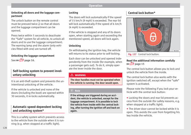
Operation
Unlocking all doors and the luggage com-partment
The unlock button on the remote controlmust be pressed twice so that all doorsand the luggage compartment can beopened.
Press twice within 5 seconds to deactivatethe “Safe” system for all vehicle, to unlock alldoors and to use the luggage compartment.The warning lamp and the alarm (only vehi-cles fitted with one) are turned off.
Unlocking the luggage compartment
See ››› page 16.
Self-locking system to prevent invol-untary unlocking
It is an anti-theft system and prevents the un-intentional unlocking of the vehicle.
If the vehicle is unlocked and none of thedoors (including the boot) are opened within30 seconds, it re-locks automatically.
Automatic speed-dependent lockingand unlocking system*
This is a safety system which prevents accessto the vehicle from the outside when it is run-ning (e.g. when stopped at a traffic light).
Locking
The doors will lock automatically if the speedof 15 km/h (9 mph) is exceeded. The rear lidwill lock automatically if the speed of 6 km/h(4 mph) is exceeded.
If the vehicle is stopped and any of its doorsopen, when starting again and exceeding thementioned speed, all doors will lock again.
Unlocking
On withdrawing the ignition key, the vehiclewill returns to its status prior to self-locking.
Each door can be unlocked and opened inde-pendently from the inside (for example, whena passenger gets out). To do it, simply oper-ate the lever inside the door.
WARNING
The door handles must not be operated whenthe vehicle is running: the door would open.
Note
If the airbags are triggered during an acci-dent, the vehicle is unlocked, except for theluggage compartment. It is possible to lockthe vehicle from inside with the central lock-ing, after turning the ignition off and back onagain.
Central lock button*
Fig. 137 Central lock button.
Read the additional information carefully››› page 15
The central lock button allows you to lock andunlock the vehicle from the inside.
The central lock button also works with theignition switched off, except when the “safe”system is activated.
Please note the following if you lock your ve-hicle with the central lock button:
● Locking the doors and rear lid prevents ac-cess from the outside (for safety reasons, e.g.when stopped at a traffic light).
● The driver door cannot be locked while it isopen. This avoids the user from forgetting hiskey inside the vehicle.
128

Opening and closing
● All doors can be unlocked separately frominside the vehicle. To do so, pull the door re-lease lever once.
WARNING
● If the vehicle is locked, children and disa-bled people may be trapped inside it.
● Repeated operation of central locking willprevent the central lock button from workingfor a few seconds. Then, it can only be un-locked in case it has been previously locked.After few seconds, the central locking be-comes operative again.
● The central lock button is not operativewhen the vehicle is locked from the outside(with the remote control or the key).
Note
● Vehicle locked, button.
● Vehicle unlocked, button.
Related videos Keyless Access
Fig. 138 Convenience
Fig. 139 Technology
Unlocking and locking the vehiclewith Keyless Access*
Fig. 140 Keyless Access locking and ignitionsystem: In the proximity of the car.
Fig. 141 Keyless Access locking and ignitionsystem: sensor surface A for unlocking in-side the door handle and sensor surface B
for locking on the exterior of the handle.
Depending on the equipment, the vehiclemay have the Keyless Access system.
Keyless Access is a key-free locking and igni-tion system to unlock and lock the vehiclewithout actively using its key. To do this, allthat is required is to have a valid vehicle keyin the detection area where you are attempt-ing to access the vehicle ››› Fig. 140 and totouch one of the sensor surfaces on the doorhandles ››› Fig. 141 ››› .
The vehicle can be unlocked and locked viathe driver door only. When doing so, the re-mote control key must be no further than ap-prox. 1.5 m from the door handle.
It does not matter where you carry the key, forinstance whether it is in your jacket pocket orin a briefcase. »
129
Tech
nica
l dat
aA
dvic
eO
pera
tion
Emer
genc
ies
Saf
ety
Operation
Once the doors have been locked, they can-not be opened again immediately. This willenable you to check that the doors are prop-erly closed.
If you wish, when unlocking, you can unlockonly the driver’s door, the side being un-locked, or the entire vehicle. The necessaryadjustments can be performed in vehicleswith a driver information system››› page 33.
General information
If a valid key is located in the proximity of thecar ››› Fig. 140, the Keyless Access lockingand starting system gives the key entry assoon as one of the sensor surfaces on thedriver door handle is touched. The followingfeatures are then available without having touse the vehicle key actively:
● Keyless-Entry: unlocking the vehicle usingthe handle of the front driver’s door or thesofttouch/handle on the rear lid.
● Keyless-Exit: locking the vehicle using thesensor on the driver door handle.
● Press & Drive: keyless starting of the en-gine with the starter button ››› page 171.
The central locking and locking systems oper-ate in the same way as a normal locking andunlocking system. Only the controls change.
Unlocking the vehicle is confirmed with adouble flash of the indicator lights; lockingby a single flash.
If the vehicle is locked and then all doors andthe rear lid are closed leaving the last keyused inside the vehicle and none outside,the vehicle will not lock immediately. All thevehicle's indicator lights will flash four times.The vehicle will lock again after a few sec-onds if you fail to open any door or the rearlid.
If you unlock the vehicle but fail to open anydoor or the rear lid, the vehicle will lock againafter a few seconds.
Unlocking and opening the doors (Keyless-Entry)
● Grip the driver door lever. In doing this, thesensor surface ››› Fig. 141 A (arrow) on thehandle is touched and the vehicle unlocks.
● Open the door.
On vehicles with selective opening or info-tainment system configuration, pulling thedoor handle twice will unlock all doors.
On vehicles without a “Safe” security sys-tem: shutting and locking doors (Keyless-Ex-it)
● Switch the ignition off.
● Close the driver's door.
● Touch (once) the locking sensor surface B
(arrow) on the driver door handle. The doorthat is used must be closed.
On vehicles with a “Safe” security system:shutting and locking doors (Keyless-Exit)
● Switch the ignition off.
● Close the driver's door.
● Touch (once) the locking sensor surface B
(arrow) on the driver door handle. The vehiclelocks with the “Safe” ››› page 127 system.The door that is used must be closed.
● Touch (twice) the sensor surface B (arrow)of the driver door handle to lock the vehiclewithout activating the “Safe” security system››› page 127.
Unlocking and locking the rear lid
When a locked vehicle is opened, the rear lidautomatically unlocks if there is a valid vehi-cle key in the proximity ››› Fig. 140.
Open or close the rear lid normally.
After closing, the rear lid locks automatically.If the complete vehicle is unlocked, the rearlid will not lock automatically after closing it.
What happens when locking the vehicle witha second key
If there is a vehicle key inside the vehicle andit is locked from the outside with a secondvehicle key, the key inside the vehicle is
130

Opening and closing
blocked for engine ignition ››› page 168. Inorder to enable engine ignition, the buttonon the key inside the vehicle needs to bepressed.
Automatically disabling sensors
If the vehicle is not locked or unlocked for along period of time, the proximity sensors onthe passenger doors are automatically disa-bled.
If one of the sensor surfaces on the door han-dles is often activated in an unusual mannerwith the vehicle locked (e.g. by the branchesof a bush rubbing against it), all proximitysensors are disabled for a certain period oftime.
Sensors will again be enabled:
● After a time.
● OR: if the vehicle is unlocked with the but-ton on the key.
● OR: if the rear lid is open.
● OR: if the vehicle is unlocked manually withthe key.
Keyless Access temporary disconnectionfunction
There is a sequence of actions to be followedif you wish to temporarily deactivate KeylessAccess. First of all, lock the vehicle with thekey. As of this moment, you have 5 seconds
to perform the second locking action throughthe door handle sensor.
If this second action is performed more than5 seconds after the vehicle is locked with thekey, it will not be possible to deactivate Key-less Access.
Once Keyless Access has been temporarilydeactivated, the vehicle can only be unlockedusing the key. The Keyless Access functionwill be reactivated once it has been unlocked.
Convenience functions
To close all the electric windows using theconvenience function, keep a finger on thelocking sensor surface ››› Fig. 141 B (arrow)of the door handle for a few seconds until thewindows have closed.
The doors opened by touching the sensorsurface of the door handle depend on thesettings that have been activated in the EasyConnect system with the button and theSETTINGS and Opening and closing function but-
tons.
CAUTION
The sensor surfaces on the door handlescould engage if hit with a water jet or highpressure steam if there is a valid vehicle keyin the proximity. If at least one of the electricwindows is open and the sensor surface B
(arrow) on the handle is activated continu-ously, all windows will close.
Note
● If the vehicle battery has little or no charge,or the vehicle key battery is almost or entire-ly out of charge, you will probably not be ableto lock or unlock the vehicle with the KeylessAccess system. The vehicle can be unlockedor locked manually.
● To control the proper locking of the vehicle,the release function is disabled for approx. 2seconds.
● If the message Keyless access systemfaulty is displayed on the screen of thedash panel, abnormalities may occur in theoperation of the Keyless Access system. Con-tact a specialised workshop. SEAT recom-mends visiting a SEAT dealership for this.
● Depending on the function set on the info-tainment system for the mirrors, the exteriormirrors will unfold and the surround lightingwill come on when unlocking the vehicle us-ing the sensor surface on the driver door han-dle.
● If there is no valid key inside the vehicle orthe system fails to detect one, a warning willdisplay on the dash panel screen. This couldhappen if any other radio frequency signal in-terferes with the key signal (e.g. from a mo-bile device accessory) or if the key is coveredby another object (e.g. an aluminium case).
● If the sensors are very dirty, e.g. have a lay-er of salt, the correct functioning of the sen-sors on the door handles may be affected. Inthis case, clean the vehicle. »
131
Tech
nica
l dat
aA
dvic
eO
pera
tion
Emer
genc
ies
Saf
ety
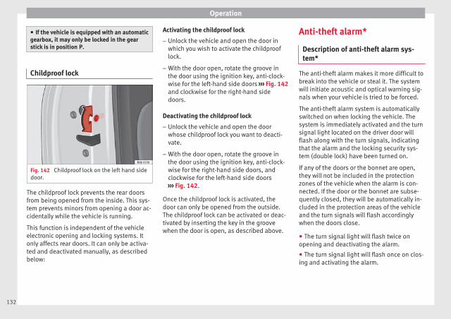
Operation
● If the vehicle is equipped with an automaticgearbox, it may only be locked in the gearstick is in position P.
Childproof lock
Fig. 142 Childproof lock on the left hand sidedoor.
The childproof lock prevents the rear doorsfrom being opened from the inside. This sys-tem prevents minors from opening a door ac-cidentally while the vehicle is running.
This function is independent of the vehicleelectronic opening and locking systems. Itonly affects rear doors. It can only be activa-ted and deactivated manually, as describedbelow:
Activating the childproof lock
– Unlock the vehicle and open the door inwhich you wish to activate the childprooflock.
– With the door open, rotate the groove inthe door using the ignition key, anti-clock-wise for the left-hand side doors ››› Fig. 142and clockwise for the right-hand sidedoors.
Deactivating the childproof lock
– Unlock the vehicle and open the doorwhose childproof lock you want to deacti-vate.
– With the door open, rotate the groove inthe door using the ignition key, anti-clock-wise for the right-hand side doors, andclockwise for the left-hand side doors››› Fig. 142.
Once the childproof lock is activated, thedoor can only be opened from the outside.The childproof lock can be activated or deac-tivated by inserting the key in the groovewhen the door is open, as described above.
Anti-theft alarm*
Description of anti-theft alarm sys-tem*
The anti-theft alarm makes it more difficult tobreak into the vehicle or steal it. The systemwill initiate acoustic and optical warning sig-nals when your vehicle is tried to be forced.
The anti-theft alarm system is automaticallyswitched on when locking the vehicle. Thesystem is immediately activated and the turnsignal light located on the driver door willflash along with the turn signals, indicatingthat the alarm and the locking security sys-tem (double lock) have been turned on.
If any of the doors or the bonnet are open,they will not be included in the protectionzones of the vehicle when the alarm is con-nected. If the door or the bonnet are subse-quently closed, they will be automatically in-cluded in the protection areas of the vehicleand the turn signals will flash accordinglywhen the doors close.
● The turn signal light will flash twice onopening and deactivating the alarm.
● The turn signal light will flash once on clos-ing and activating the alarm.
132

Opening and closing
When does the system trigger an alarm?
The system triggers an alarm, if the followingunauthorised actions are carried out whenthe vehicle is locked:
● Mechanical opening of the vehicle with thevehicle key without switching on the ignitionin the next 15 seconds (in certain markets,such as the Netherlands, the alarm is activa-ted immediately).
● A door is opened.
● Opening the bonnet.
● The rear lid is opened.
● Ignition switched on with a non-validatedkey.
● Movements in the driving compartment(vehicles with a volume sensor).
● Towing of the vehicle1).
● Vehicle tilt angle1).
● Undue manipulation of the alarm.
● Battery handling.
In this case, the acoustic signals will go offand the turn signal will flash for approximate-ly 30 seconds. This cycle may be repeated upto 10 times depending on the country.
Opening all the doors in manual mode
In vehicles without an alarm, when openingthe driver door manually, all doors areopened.
How to switch the alarm off
To deactivate the anti-theft alarm, turn thekey in the opening direction, open the doorand switch the ignition on, or press the un-lock button on the remote control.
In vehicles equipped with an anti-theft alarmsystem, you have 15 seconds to insert thekey in the ignition lock and activate the igni-tion if the vehicle is opened using the driverdoor key.
Otherwise, the alarm will trigger for 30 sec.and the ignition will be blocked.
Note
● After 28 days, the indicator light will beswitched off to prevent the battery fromdraining if the vehicle has been left parkedfor a long period of time. The alarm systemremains activated.
● The alarm will trigger again if attempts aremade to open another protection zone.
● The alarm system can be activated or deac-tivated using the radio frequency remote con-trol ››› page 124.
● The anti-theft alarm is not activated whenthe vehicle is locked from within using thecentral locking button .
● If the vehicle battery is run down or flatthen the anti-theft alarm will not operate cor-rectly.
● Vehicle monitoring remains active even ifthe battery is disconnected or not working forany reason.
● The alarm is triggered immediately if one ofthe battery cables is disconnected while thealarm system is active.
Vehicle interior monitoring and anti-tow system*
Monitoring or control function incorporatedin the anti-theft alarm* which detects unau-thorised vehicle entry by means of ultra-sound.
Activation
– It is automatically switched on when theanti-theft alarm is activated.
Deactivation
– Open the vehicle with the key, either me-chanically or by pressing the button onthe remote control. If the vehicle is opened »
1) With vehicles fitted with a tow-away protection133
Tech
nica
l dat
aA
dvic
eO
pera
tion
Emer
genc
ies
Saf
ety

Operation
mechanically, the time period from whenthe door is opened until the key is insertedinto the contact should not exceed 15 sec-onds, otherwise the alarm will be triggered.
– Press the button on the remote controltwice. The volumetric sensor and tilt sen-sors will be deactivated. The alarm systemremains activated.
The vehicle interior monitoring and the anti-tow system are automatically switched onagain next time the vehicle is locked.
The vehicle interior monitoring and anti-towsensor (tilt sensor) are automatically switch-ed on when the anti-theft alarm is switchedon. In order to activate it, all the doors andthe rear lid must be closed.
If you wish to switch off the vehicle interiormonitoring and the anti-tow system, it mustbe done each time that the vehicle is locked;if not, they will be automatically switched on.
The vehicle interior monitoring and the anti-tow system should be switched off if animalsare left inside the locked vehicle (otherwise,their movements will trigger the alarm) orwhen, for example, the vehicle is transportedor has to be towed with only one axle on theground.
False alarms
Interior monitoring will only operate correctlyif the vehicle is completely closed. Please ob-serve related legal requirements.
The following cases may cause a false alarm:
● Open windows (partially or fully),
● Movement of objects inside the vehicle,such as loose papers, items hanging fromthe rear vision mirror (air fresheners), etc.
Note
● If the vehicle is relocked and the alarm isactivated without the volumetric sensor func-tion, relocking will activate the alarm with allits functions, except the volumetric sensor.This function is reactivated when the alarm isswitched on again, unless it is deliberatelyswitched off.
● If the alarm has been triggered by the volu-metric sensor, this will be indicated by aflashing of the warning lamp on the driverdoor when the vehicle is opened. The flash isdifferent to the flash indicating the alarm isactivated.
● The vibration of a mobile phone left insidethe vehicle may cause the vehicle interiormonitoring alarm to trigger, as both sensorsreact to movements and shakes inside the ve-hicle.
● If on activating the alarm, any door or therear lid is open, only the alarm will be activa-ted. The vehicle interior monitoring and the
anti-tow system will only be activated onceall the doors are closed (including the rearlid).
Deactivating the vehicle interior moni-toring and anti-tow systems*
When the vehicle is locked, the alarm will betriggered if movements are detected in theinterior (e.g. by animals) or if the vehicle's in-clination is changed (e.g. during transport).You can prevent the alarm from being trig-gered accidentally by switching off the vehi-cle interior monitoring and/or tow-away pro-tection.
– To switch off the interior monitoring andtow-away protection, switch off the ignitionand, using the Infotainment system, select: button > SETTINGS function button >
Opening and closing > Central locking >Switch off alarm.
– When the vehicle is locked now, the vehicleinterior monitoring and the tow-away pro-tection are switched off until the next timethe door is opened.
If the anti-theft security system (Safelock)*››› page 127 is switched off, the vehicle interi-or monitoring and the tow-away protectionare automatically switched off.
134
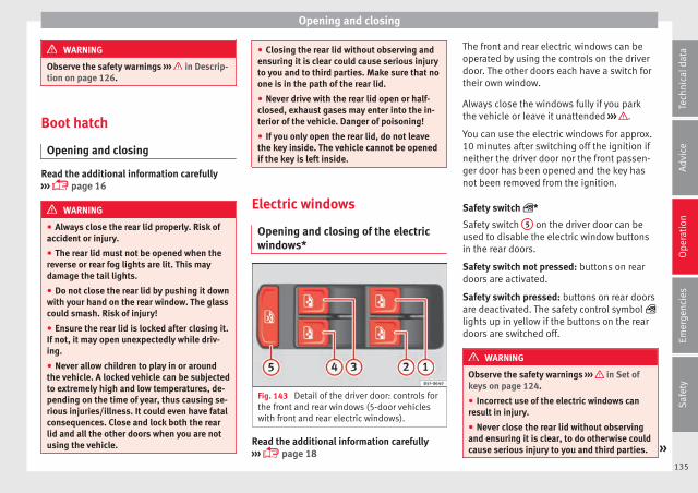
Opening and closing
WARNING
Observe the safety warnings ››› in Descrip-tion on page 126.
Boot hatch
Opening and closing
Read the additional information carefully››› page 16
WARNING
● Always close the rear lid properly. Risk ofaccident or injury.
● The rear lid must not be opened when thereverse or rear fog lights are lit. This maydamage the tail lights.
● Do not close the rear lid by pushing it downwith your hand on the rear window. The glasscould smash. Risk of injury!
● Ensure the rear lid is locked after closing it.If not, it may open unexpectedly while driv-ing.
● Never allow children to play in or aroundthe vehicle. A locked vehicle can be subjectedto extremely high and low temperatures, de-pending on the time of year, thus causing se-rious injuries/illness. It could even have fatalconsequences. Close and lock both the rearlid and all the other doors when you are notusing the vehicle.
● Closing the rear lid without observing andensuring it is clear could cause serious injuryto you and to third parties. Make sure that noone is in the path of the rear lid.
● Never drive with the rear lid open or half-closed, exhaust gases may enter into the in-terior of the vehicle. Danger of poisoning!
● If you only open the rear lid, do not leavethe key inside. The vehicle cannot be openedif the key is left inside.
Electric windows
Opening and closing of the electricwindows*
Fig. 143 Detail of the driver door: controls forthe front and rear windows (5-door vehicleswith front and rear electric windows).
Read the additional information carefully››› page 18
The front and rear electric windows can beoperated by using the controls on the driverdoor. The other doors each have a switch fortheir own window.
Always close the windows fully if you parkthe vehicle or leave it unattended ››› .
You can use the electric windows for approx.10 minutes after switching off the ignition ifneither the driver door nor the front passen-ger door has been opened and the key hasnot been removed from the ignition.
Safety switch *
Safety switch 5 on the driver door can beused to disable the electric window buttonsin the rear doors.
Safety switch not pressed: buttons on reardoors are activated.
Safety switch pressed: buttons on rear doorsare deactivated. The safety control symbol lights up in yellow if the buttons on the reardoors are switched off.
WARNING
Observe the safety warnings ››› in Set ofkeys on page 124.
● Incorrect use of the electric windows canresult in injury.
● Never close the rear lid without observingand ensuring it is clear, to do otherwise couldcause serious injury to you and third parties. »
135
Tech
nica
l dat
aA
dvic
eO
pera
tion
Emer
genc
ies
Saf
ety

Operation
Make sure that no one is in the path of a win-dow.
● If the ignition is switched on, the electricequipment could be activated with risk of in-jury, for example, in the electric windows.
● The doors can be locked using the remotecontrol key. This could become an obstaclefor assistance in an emergency situation.
● Therefore always take the key with youwhen you leave the vehicle.
● The electric windows will work until the ig-nition has been switched off and one of thefront doors has been opened.
● If necessary, use the safety switch to disa-ble the rear electric windows. Make sure thatthey have been disabled.
Note
If the window is not able to close because itis stiff or because of an obstruction, the win-dow will automatically open again››› page 136. If this happens, check why thewindow could not be closed before attempt-ing to close it again.
Roll-back function
The roll-back function reduces the risk of in-jury when the electric windows close.
● If a window is obstructed when closing au-tomatically, the window stops at this pointand lowers immediately ››› .
● Next, check why the window does not closebefore attempting it again.
● If you try within the following 10 secondsand the window closes again with difficultyor there is an obstruction, the automatic clos-ing will stop working for 10 seconds.
● If the window is still obstructed, the win-dow will stop at this point.
● If there is no obvious reason why the win-dow cannot be closed, try to close it again bypulling the tab within ten seconds. The win-dow closes with maximum force. The roll-back function is now deactivated.
If more than 10 seconds pass, the windowwill open fully when you operate one of thebuttons. One-touch closing is reactivated.
WARNING
● Always take the ignition key with you whenleaving the vehicle, even if you only intend tobe gone for a short time. Please ensure thatchildren are never left alone inside the vehi-cle.
● The electric windows will work until the ig-nition has been switched off and one of thefront doors has been opened.
● Closing the windows without observing andensuring it is clear could cause serious injury
to you and third parties. Make sure that noone is in the path of a window.
● Never allow people to remain in the vehiclewhen you close the vehicle from the outside.The windows cannot be opened even in anemergency.
● The roll-back function does not prevent fin-gers or other parts of the body gettingpinched against the window frame. Risk ofaccident.
Convenience opening and closing
Use the convenience opening/closing func-tion to easily open/close all the windowsfrom the outside.
Convenience open function
– Press and hold the button on the remotecontrol key until all the windows havereached the desired position, or
– First unlock the vehicle using the buttonon the remote control key and then keepthe key in the driver door lock until all thewindows have reached the required posi-tion.
Convenience close function
– Press and hold the button on the remotecontrol key until all the windows are closed››› , or
136
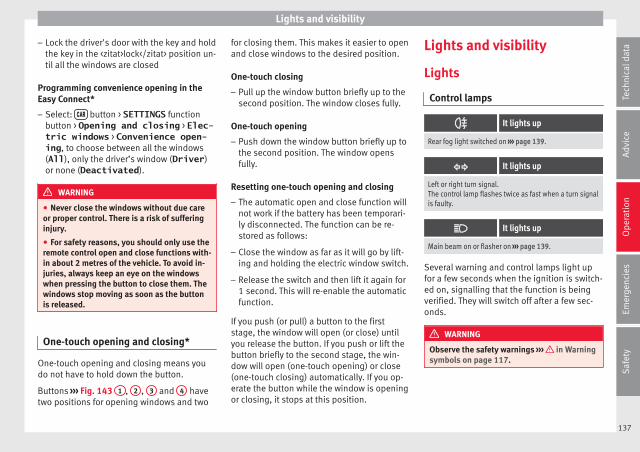
Lights and visibility
– Lock the driver's door with the key and holdthe key in the <zitat>lock</zitat> position un-til all the windows are closed
Programming convenience opening in theEasy Connect*
– Select: button > SETTINGS functionbutton > Opening and closing > Elec-tric windows > Convenience open-ing, to choose between all the windows(All), only the driver’s window (Driver)or none (Deactivated).
WARNING
● Never close the windows without due careor proper control. There is a risk of sufferinginjury.
● For safety reasons, you should only use theremote control open and close functions with-in about 2 metres of the vehicle. To avoid in-juries, always keep an eye on the windowswhen pressing the button to close them. Thewindows stop moving as soon as the buttonis released.
One-touch opening and closing*
One-touch opening and closing means youdo not have to hold down the button.
Buttons ››› Fig. 143 1 , 2 , 3 and 4 havetwo positions for opening windows and two
for closing them. This makes it easier to openand close windows to the desired position.
One-touch closing
– Pull up the window button briefly up to thesecond position. The window closes fully.
One-touch opening
– Push down the window button briefly up tothe second position. The window opensfully.
Resetting one-touch opening and closing
– The automatic open and close function willnot work if the battery has been temporari-ly disconnected. The function can be re-stored as follows:
– Close the window as far as it will go by lift-ing and holding the electric window switch.
– Release the switch and then lift it again for1 second. This will re-enable the automaticfunction.
If you push (or pull) a button to the firststage, the window will open (or close) untilyou release the button. If you push or lift thebutton briefly to the second stage, the win-dow will open (one-touch opening) or close(one-touch closing) automatically. If you op-erate the button while the window is openingor closing, it stops at this position.
Lights and visibility
Lights
Control lamps
It lights up
Rear fog light switched on ››› page 139.
It lights up
Left or right turn signal.The control lamp flashes twice as fast when a turn signalis faulty.
It lights up
Main beam on or flasher on ››› page 139.
Several warning and control lamps light upfor a few seconds when the ignition is switch-ed on, signalling that the function is beingverified. They will switch off after a few sec-onds.
WARNING
Observe the safety warnings ››› in Warningsymbols on page 117.
137
Tech
nica
l dat
aA
dvic
eO
pera
tion
Emer
genc
ies
Saf
ety
Operation
Switching lights on and off
Read the additional information carefully››› page 30
The driver is personally responsible for thecorrect use and adjustment of the lights in allsituations.
Note
● The legal requirements regarding the use ofvehicle lights in each country must be ob-served.
● The dipped beam headlights will only workwith the ignition on. The side lights come onautomatically when the ignition is turned off.
● If the lights are left on after the key hasbeen taken out of the ignition lock, an audi-ble warning sounds while the driver door re-mains open. This is a reminder to switch thelights off.
● The rear fog light can dazzle drivers behindyou. You should use the rear fog light onlywhen visibility is very poor. For this reason, ifyou exceed approximately 60 km/h (38 mph),the instrument panel will display the follow-ing warming: Switch off the foglight!● The use of the lighting described here issubject to the relevant statutory require-ments.
Automatic lighting*
Activation
– Rotate the switch to the position, thisindication will light up.
Deactivation
– Turn the light switch to .
Automatic lighting
If automatic headlight control is switched on,dipped beam headlights are automaticallyswitched on by a photosensor if you drive in-to a tunnel, for example.
WARNING
● Even if the automatic headlight control isswitched on, the dipped beam headlights willnot be switched on with fog. Therefore, thedipped beam must be switched on manually.
Note
● For vehicles with the automatic headlightsystem, when the key is removed from the ig-nition, the audible warning will only sound ifthe light knob is in position .
● The use of the lighting described here issubject to the relevant statutory require-ments.
● Do not put stickers on the windscreen infront of the sensor. This may cause disrup-tions or faults in the automatic lighting sys-tem.
● The rain sensor switches on the dippedbeam headlights when the windscreen wipershave been operating continuously for a fewseconds and it switches the lights off whenthe continuous or interval wipe is switchedoff for some minutes.
Daytime running lights
The daytime running lights consist of individ-ual lights, integrated in the front headlights.By connecting the daytime running lights,these lights are switched on1) ››› .
The daytime running lights switch on everytime the ignition is switched on, if the switchis in positions or , according to the levelof exterior lighting.
When the light switch is in position , alight sensor automatically switches dippedbeam on and off (including the control andinstrument lighting) or the daytime runninglights depending on the level of exteriorlighting.
1) On vehicles equipped with rear LED lights, the rearside light is switched on as well.
138
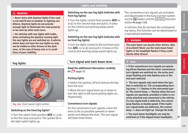
Lights and visibility
WARNING
● Never drive with daytime lights if the roadis not well lit due to weather or lighting con-ditions. Daytime lights do not provideenough light to illuminate the road properlyor be seen by other road users.
● On vehicles with rear lights with bulbs,when activating the daytime running lightthe rear lights are not switched on. A vehiclewhich does not have the rear lights on maynot be visible to other drivers in the dark-ness, in the case of heavy rain or in condi-tions of poor visibility.
Fog lights
Fig. 144 Dash panel: light control.
Switching on the front fog lights*
● Turn the switch from position or to the first stop and pull it. The symbol inthe light switch lights up.
Switching on the rear fog light (vehicles withfront fog lights)
● Turn the lights control from position or to the second stop and pull it. A lampon the control and warning lamps panellights up.
Switching on the rear fog light (vehicles withno front fog lights)
● Turn the lights control to the end from posi-tion , or and pull it. A lamp on thecontrol and warning lamps panel lights up.
Turn signal and main beam lever
Read the additional information carefully››› page 31
Parking lights
● Switch the ignition off and remove the keyfrom the lock.
● Move the turn signal lever up or down toturn the right or left-hand parking lights on,respectively.
Convenience turn signals
For the convenience turn signals, move thelever as far as possible upwards or down-wards and release the lever. The turn signalwill flash three times.
The convenience turn signals are activatedand deactivated in the Easy Connect systemvia the button and the SETTINGS functionbutton ››› page 118.
In vehicles that do not have the correspond-ing menu, this function can be deactivated ina specialised workshop.
WARNING
The main beam can dazzle other drivers. Riskof accident! Never use the main beam head-lights or the headlight flasher if they coulddazzle other drivers.
Note
● If the convenience turn signals are operat-ing (three flashes) and the other convenienceturn signals are switched on, the active partstops flashing and only flashes once in thenew part selected.
● The turn signals only work when the igni-tion is switched on. The corresponding warn-ing lamp flashes in the instrument pan-el. The control lamp flashes when the turnsignals are operated, provided a trailer is cor-rectly attached and connected to the vehicle.If a turn signal bulb is defective, the controllamp flashes at double speed. If the trailerturn signal bulbs are defective, the controllamp does not light up. Change the bulb.
● The main beam headlights can only beswitched on if the dipped beam headlights »
139
Tech
nica
l dat
aA
dvic
eO
pera
tion
Emer
genc
ies
Saf
ety
Operation
are already on. The warning lamp thencomes on in the instrument panel.
● The headlight flasher comes on for as longas you pull the lever – even if no other lightsare switched on. The warning lamp thencomes on in the instrument panel.
● When the parking lights are switched on,the headlight and the tail light on the corre-sponding side of the vehicle light up. Theparking lights will only work with the ignitionoff. If said light is on, an audible warning willbe emitted while the driver door is open.
● If the turn signal lever is left on after thekey has been taken out of the ignition lock,an acoustic signal sounds when the driverdoor is opened. This is intended as a remind-er to switch off the turn signal, unless youwish to leave the parking light on.
Coming Home/Leaving Home Func-tion*
Fig. 145 Related video
The Leaving Home function is controlled witha photosensor.
If the Coming Home or Leaving Home func-tion is connected, the front side and dippedlights, the tail lights and the number platelight will light up to provide assistance.
Coming home function
The Coming Home function is activated byswitching off the ignition. When the driverdoor is opened, the Coming Home lightingcomes on.
The Coming Home lighting switches off in thefollowing cases:
● If, 30 seconds after being connected, anydoors or the rear lid remain open.
● If the light switch is turned to position .
● If the ignition is switched on.
Automatic Leaving Home function
The Leaving Home function is activated whenthe vehicle is unlocked if:
● the light control is in position and
● the photosensor detects “darkness”.
The Leaving Home lighting switches off in thefollowing cases:
● If the time period for the delay in switchingoff the headlights has ended
● If the vehicle is locked again.
● If the light switch is turned to position .
● If the ignition is switched on.
Note
● To activate the Coming/Leaving home func-tion, the rotary light switch must be in posi-tion and the light sensor must detectdarkness.
Fog lights with cornering function*
This is an additional light source to dippedbeam headlights to light up the road as abend is taken.
The cornering light operates with the lightsswitched on and when driving at less than40 Km/h (25 mph). Ignition occurs by turningthe steering or connecting the turn signal.
Forward gear
● If the steering wheel is turned to the right,or the right-hand turn signal operated, theright-hand fog light turns on.
● If the steering wheel is turned to the left, orthe left-hand turn signal operated, the left-hand fog light turns on.
In reverse, both fog lights turn on.
Note
When the fog lamps are on, the corneringfunction is activated and both headlights arecontinuously on.
140

Lights and visibility
Motorway light*
The motorway light is available on vehiclesequipped with full-LED lights.
The function is connected/disconnected viathe corresponding Easy Connect systemmenu.
● Activation: when going above 110 km/h(68 mph) for more than 10 seconds, the dip-ped beam raises slightly to increase the driv-er's visibility distance.
● Deactivation: when reducing the speed ofthe car below 100 km/h (62 mph), the dip-ped beam returns to its normal position.
Headlight range control
Fig. 146 Dash panel: headlight range control.
The lights range control adapts according tothe value of the headlight beam and the ve-
hicle load status. This offers the driver opti-mum visibility and the headlights do not daz-zle oncoming drivers ››› .
The headlights can only be adjusted whenthe dipped beam is switched on.
To reset, turn switch ››› Fig. 146:
Value Vehicle load statusa)
–Two front occupants, luggage compart-ment empty
1All seats occupied, luggage compartmentempty
2All seats occupied, luggage compartmentfull. With trailer and minimum drawbarload.
3Driver only, luggage compartment full Withtrailer and maximum drawbar load.
a) If the vehicle load does not correspond to those shown in thetable, it is possible to select intermediary positions.
Dynamic headlight range control
The control is not mounted in vehicles withdynamic headlight range control. The head-light range is automatically adjusted accord-ing to the vehicle load status when they areswitched on.
WARNING
Heavy objects in the vehicle may mean thatthe headlights dazzle and distract other driv-ers. This could result in a serious accident.
● Adjust the light beam to the vehicle loadstatus so that it does not blind other drivers.
Hazard warning lights
Read the additional information carefully››› page 31
The hazard warning lights are used to drawthe attention of other road users to your vehi-cle in emergencies.
If your vehicle breaks down:
1. Park your vehicle at a safe distance frommoving traffic.
2. Press the button to switch on the hazardwarning lights ››› .
3. Switch the ignition off.
4. Apply the handbrake.
5. For a manual gearbox, engage 1st gear;for an automatic gearbox, move the gearlever to P.
6. Use the warning triangle to draw the atten-tion of other road users to your vehicle.
7. Always take the vehicle key with you whenyou leave the vehicle. »
141
Tech
nica
l dat
aA
dvic
eO
pera
tion
Emer
genc
ies
Saf
ety

Operation
All turn signals flash simultaneously whenthe hazard warning lights are switched on.The two turn signal turn signal lamps and the turn signal lamp in the switch willflash at the same time. The simultaneoushazard warning lights also work when the ig-nition is switched off.
WARNING
● The risk of an accident increases if your ve-hicle breaks down. Always use the hazardwarning lights and a warning triangle to drawthe attention of other road users to your sta-tionary vehicle.
● Due to the high temperatures that the cata-lytic converter can reach, never park in anarea where the catalytic converter could comeinto contact with highly inflammable materi-als, for example dry grass or spilt petrol. Thiscould start a fire.
Note
● The battery will run down if the hazardwarning lights are left on for a long time,even if the ignition is switched off.
● The use of the hazard warning lights de-scribed here is subject to the relevant statu-tory requirements.
Interior lights
Related video
Fig. 147 Convenience
Lighting of instruments and controls
The lighting level of instruments, controlsand displays can be adjusted through theEasy Connect system using the buttonand the SETTINGS function button››› page 33.
The instrument lighting (some dials and nee-dles), the centre console lighting and thelighting of the displays are regulated by aphotodiode incorporated in the instrumentpanel.
The instrument lighting (needles) is switchedon when the ignition is on and the light isoff. The instrument lighting is dimmed auto-matically as the daylight starts to fade. Itgoes out completely when ambient light isvery low. This function is intended to remindthe driver to switch on the dipped beam
headlights in good time when light condi-tions become poor.
Interior and reading lights
Read the additional information carefully››› page 32
Luggage compartment lighting
The light is activated when the rear lid isopen, even when the ignition and lights areturned off. For this reason, ensure that therear lid is always closed.
Ambient light*
The ambient light lights up the area of thecentre console and the footwell area and, de-pending on the version, the front door panelsas well.
It will be switched on at full brightness whenthe doors are opened and the lights will bedimmed during driving, when the light selec-tor is in the , or position.
The brightness of the ambient light* can beadjusted through the Easy Connect menu, ascan colour, in versions with lighting on thefront door panel (see Adjusting Lights >Interior lighting ››› page 33).
142

Lights and visibility
Note
If not all the vehicle doors are closed, the in-terior lights will be switched off after approx.10 minutes, providing the ignition key hasbeen removed and the courtesy light positionselected. This prevents the battery from dis-charging.
Visibility
Heated rear window
Fig. 148 With the air conditioning controls:heated rear window switch.
The heated rear window only works when theengine is running. When it is switched on, alamp lights up on the switch.
After approximately 8 minutes, the heatingdevice of the rear window switches off auto-matically.
For the sake of the environment
The heated rear window should be switchedoff as soon as the glass is demisted. By sav-ing electrical power you can also save fuel.
Note
To avoid possible damage to the battery, anautomatic temporary disconnection of thisfunction is possible, coming back on whennormal operating conditions are re-establish-ed.
Sun visors
Fig. 149 Sun visor on the driver side.
Options for adjusting driver and front pas-senger sun visors:
● Lower the sun visor towards the wind-screen.
● The sun visor can be pulled out of itsmounting and turned towards the door››› Fig. 149 1 .
● Swing the sun visor towards the door, lon-gitudinally backwards.
Vanity mirror
There is a vanity mirror, with a cover 2 , onthe rear of the sun blind.
WARNING
Folded sun blinds can reduce visibility.
● Always store sun blinds and visors in theirhousing when not in use.
Windscreen wiper and rear win-dow wiper systems
Windscreen wiper and window wiper
Read the additional information carefully››› page 32
WARNING
● Worn and dirty wiper blades reduce visibili-ty and safety levels while driving.
● In cold conditions you should not use thewash/wipe system unless you have warmedthe windscreen with the heating and ventila-tion system. The windscreen washer fluid »
143
Tech
nica
l dat
aA
dvic
eO
pera
tion
Emer
genc
ies
Saf
ety
Operation
could otherwise freeze on the windscreen andobscure your view of the road.
● Always note the corresponding warnings››› page 69.
WARNING
The rain sensor* may not detect enough rainto switch on the wipers.
● If necessary, switch on the wipers manuallywhen water on the windscreen obstructs visi-bility.
CAUTION
In icy conditions, always check that the wind-screen wipers and the window wiper are notfrozen. If you switch on the windscreen wip-ers when the wiper blades are frozen to thewindscreen, you could damage both the wip-er blades and the wiper motor.
Note
● The wipers and washers will work onlywhen the ignition is switched on.
● The heat output of the heated jets* is con-trolled automatically when the ignition isswitched on, depending upon the outsidetemperature.
● In certain versions of vehicles with alarms,the windscreen wiper will only work in inter-val/rain sensor mode when the ignition is onand the bonnet closed.
● When the interval wipe function is on, theintervals are directly proportional to thespeed. This way, the higher the vehicle speedthe shorter the intervals.
● If you stop the vehicle with the windscreenwiper in position 1 or 2, it will automaticallychange to a lower position speed. The setspeed will be resumed when the vehicle pullsaway.
● The windscreen will be wiped again afterapproximately five seconds once the “auto-matic wash/wipe system” has been activa-ted, provided the vehicle is moving (drip func-tion). If you activate the wipers less than 3seconds after the drip function, a new washsequence will begin without performing thelast wipe. For the “drip” function to workagain, you have to turn the ignition off andthen on again.
● Do not put stickers on the windscreen infront of the rain sensor*. This may cause sen-sor disruption or faults.
● Depending on the version of the model,when you engage reverse gear and with theheadlight wiper activated, this can start awipe.
Rear view mirrors
Interior mirror
It is dangerous to drive if you cannot seeclearly through the rear window.
Interior mirror with automatic anti-dazzlefunction*
The anti-dazzle function is activated everytime the ignition is switched on.
When the anti-dazzle function is enabled, theinterior rear vision mirror will darken auto-matically according to the amount of light itreceives. The anti-dazzle function is cancel-led if reverse gear is engaged.
Note
● The automatic anti-dazzle function will onlywork properly if the sun blind* for the rearwindow is retracted and there are no otherobjects preventing light from reaching the in-terior rear vision mirror.
● If you have to stick any type of sticker onthe windscreen, do not do so in front of thesensors. Doing so could prevent the anti-daz-zle function from working well or even fromworking at all.
Folding in the exterior mirrors man-ually
The exterior mirrors of the vehicle may be fol-ded in. For this, press the mirror housing to-wards the vehicle.
144
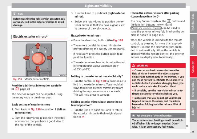
Lights and visibility
Note
Before washing the vehicle with an automaticcar wash, fold in the exterior mirrors to avoiddamage.
Electric exterior mirrors*
Fig. 150 Exterior mirror controls.
Read the additional information carefully››› page 20
The exterior mirrors can be adjusted usingthe rotary knob in the driver door.
Basic setting of exterior mirrors
1. Turn knob ››› Fig. 150 to position L (left ex-terior mirror).
2. Turn the rotary knob to position the exteri-or mirror so that you have a good view tothe rear of the vehicle.
3. Turn the knob to position R (right exteriormirror).
4. Swivel the rotary knob to position the ex-terior mirror so that you have a good viewto the rear of the vehicle ››› .
Heated exterior mirrors*
– Press the demisting button ››› Fig. 148
– The mirrors demist for some minutes toprevent draining the battery unnecessarily.
– If necessary, press the button again to re-peat the function.
– The exterior mirror heating is not activatedin temperatures above approximately+20°C (+68°F).
Folding in the exterior mirrors electrically*
– Turn the control ››› Fig. 150 to position tofold in the exterior mirrors. You should al-ways fold in the exterior mirrors if you aredriving through an automatic car wash.This will help prevent damage.
Folding exterior mirrors back out to the ex-tended position*
– Turn the knob to position L or R to returnthe exterior mirrors to their original posi-tion ››› .
Fold in the exterior mirrors after parking(convenience function)*
The Easy Connect system, the button andthe function buttons SETTINGS andMirrors and windscreen wipers can be used to
have the exterior mirrors fold in when the ve-hicle is parked ››› page 118.
When the vehicle is locked with the remotecontrol, by pressing for more than approxi-mately 1 second the exterior mirrors are fol-ded in automatically. When the vehicle isopened with the remote control, the exteriormirrors are deployed automatically.
WARNING
● Convex or aspheric mirrors increase thefield of vision however the objects appearsmaller and further away in the mirrors. If youuse these mirrors to estimate the distance tovehicles behind you when changing lane, youcould make a mistake. Risk of accident.
● If possible, use the rear vision mirror to es-timate distances to vehicles behind you.
● Make sure that you do not get your fingertrapped between the mirror and the mirrorbase when folding back the mirrors. Risk ofinjury!
For the sake of the environment
The exterior mirror heating should be switch-ed off when it is no longer needed. Other-wise, it is an unnecessary fuel waste. »
145
Tech
nica
l dat
aA
dvic
eO
pera
tion
Emer
genc
ies
Saf
ety

Operation
Note
● If the electrical adjustment ever fails to op-erate, the mirrors can be adjusted by hand bylightly pressing the edge of the mirror glass.
● In vehicles with electric exterior mirrors,the following points should be observed: if,due to an external force (e.g. being knockedwhile manoeuvring), the adjustment of themirror housing is altered, the mirror will haveto be fully folded electrically. Do not readjustthe rear vision mirror housing by hand, asthis will interfere with the mirror adjusterfunction.
● The fold-in function on the exterior mirrorswill not activate at speeds over 40 km/h(25 mph).
Seats and head restraints
Adjusting the seat and head re-straints
Adjusting the front seats
Read the additional information carefully››› page 18
WARNING
The safe driving chapter contains importantinformation, tips, suggestions and warningsthat you should read and observe for yourown safety and the safety of your passengers››› page 71.
WARNING
● Never adjust the driver or front passengerseat while the vehicle is in motion. While ad-justing your seat, you will assume an incor-rect sitting position. Risk of accidents. Adjustthe driver or front passenger seat only whenthe vehicle is stationary.
● To reduce the risk of injury to the driver andfront passenger in case of a sudden brakingor an accident, never drive with the backresttilted towards the rear. The maximum protec-tion of the seat belt can be achieved onlywhen the backrests are in an upright positionand the driver and front passenger have prop-erly adjusted their seat belts. The further the
backrests are tilted to the rear, the greaterthe risk of injury due to improper positioningof the belt web!
● Exercise caution when securing the seatheight into forwards/backwards position. In-juries can be caused if the seat height is ad-justed without due care and attention.
● To move the seat forwards and backwards,pull upwards and not sideways on the lever,as the force exerted on it in that directioncould damage it.
Adjusting the front head restraints
Read the additional information carefully››› page 19
Adjust the head restraint ››› page 19 sothat as far as possible the top of the head re-straint is level with the top of your head.When this is not possible, try to get as closeas possible to this position.
WARNING
● Never drive if the head restraints have beenremoved. Risk of injury.
● After refitting the head restraint, you mustalways adjust it properly for height to achieveoptimal protection.
● Please observe the safety warnings ››› inCorrect adjustment of front head restraints onpage 75.
146
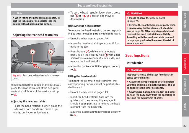
Seats and head restraints
Note
● When fitting the head restraints again, in-sert the tubes as far as possible into theguides without pressing the button.
Adjusting the rear head restraints
Fig. 151 Rear centre head restraint: releasepoint.
When transporting people in the back seat,place the head restraints of the occupiedseats at a minimum of the next socket up››› .
Adjusting the head restraints
– To set the head restraint higher, grasp thesides with both hands and move it up-wards, until you see it engage.
– To set the head restraint lower down, pressthe 1 ››› Fig. 151 button and move itdownwards.
Removing the head restraint
To remove the head restraint, the correspond-ing backrest must be partially folded forward.
– Unlock the backrest ››› page 149.
– Move the head restraint upwards until it ar-rives to the top.
– Press button 1 , while simultaneouslypressing on the security hole 2 with a flatscrewdriver a maximum of 5 mm wide, andremove the head restraint.
– Move the backrest until it engages properly››› .
Fitting the head restraint
To mount the external head restraints, thecorresponding backrest must be partially fol-ded forward.
– Unlock the backrest ››› page 149.
– Insert the head restraint bars into theguides until they perceptibly engage. Itshould not be possible to remove the headrestraint from the backrest.
– Move the backrest until it engages properly››› .
WARNING
● Please observe the general notes››› page 75.
● Remove the rear head restraints only whenit is necessary for the placement of a childseat ››› page 88. After removing a child seat,remount the head restraint immediately.Travelling with the head restraints removedor improperly adjusted increases the risk ofsevere injuries.
Seat functions
Introduction
WARNING
Inappropriate use of the seat functions cancause severe injuries.
● Assume the proper sitting position beforeyour trip and remain in it throughout. This al-so applies to the other occupants.
● Always keep hands, fingers, feet and otherparts of the body away from the operating ra-dius and the adjustment of seats.
147
Tech
nica
l dat
aA
dvic
eO
pera
tion
Emer
genc
ies
Saf
ety
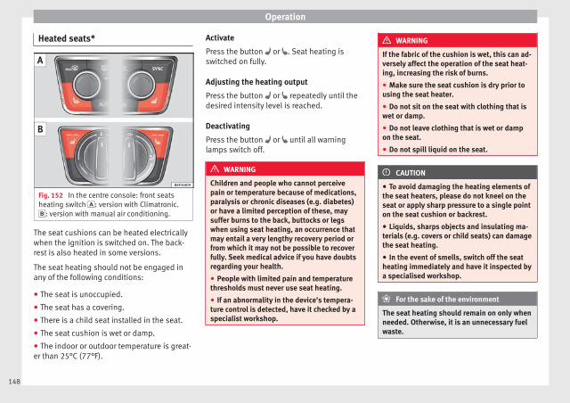
Operation
Heated seats*
Fig. 152 In the centre console: front seatsheating switch : version with Climatronic.: version with manual air conditioning.
The seat cushions can be heated electricallywhen the ignition is switched on. The back-rest is also heated in some versions.
The seat heating should not be engaged inany of the following conditions:
● The seat is unoccupied.
● The seat has a covering.
● There is a child seat installed in the seat.
● The seat cushion is wet or damp.
● The indoor or outdoor temperature is great-er than 25°C (77°F).
Activate
Press the button or . Seat heating isswitched on fully.
Adjusting the heating output
Press the button or repeatedly until thedesired intensity level is reached.
Deactivating
Press the button or until all warninglamps switch off.
WARNING
Children and people who cannot perceivepain or temperature because of medications,paralysis or chronic diseases (e.g. diabetes)or have a limited perception of these, maysuffer burns to the back, buttocks or legswhen using seat heating, an occurrence thatmay entail a very lengthy recovery period orfrom which it may not be possible to recoverfully. Seek medical advice if you have doubtsregarding your health.
● People with limited pain and temperaturethresholds must never use seat heating.
● If an abnormality in the device's tempera-ture control is detected, have it checked by aspecialist workshop.
WARNING
If the fabric of the cushion is wet, this can ad-versely affect the operation of the seat heat-ing, increasing the risk of burns.
● Make sure the seat cushion is dry prior tousing the seat heater.
● Do not sit on the seat with clothing that iswet or damp.
● Do not leave clothing that is wet or dampon the seat.
● Do not spill liquid on the seat.
CAUTION
● To avoid damaging the heating elements ofthe seat heaters, please do not kneel on theseat or apply sharp pressure to a single pointon the seat cushion or backrest.
● Liquids, sharps objects and insulating ma-terials (e.g. covers or child seats) can damagethe seat heating.
● In the event of smells, switch off the seatheating immediately and have it inspected bya specialised workshop.
For the sake of the environment
The seat heating should remain on only whenneeded. Otherwise, it is an unnecessary fuelwaste.
148
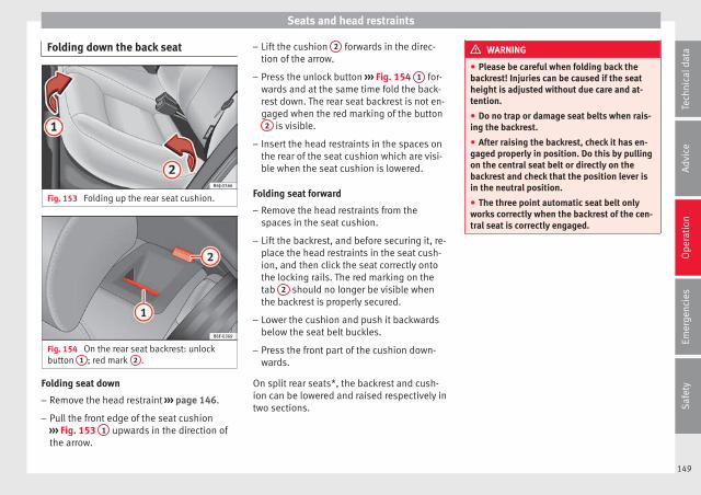
Seats and head restraints
Folding down the back seat
Fig. 153 Folding up the rear seat cushion.
Fig. 154 On the rear seat backrest: unlockbutton 1 ; red mark 2 .
Folding seat down
– Remove the head restraint ››› page 146.
– Pull the front edge of the seat cushion››› Fig. 153 1 upwards in the direction ofthe arrow.
– Lift the cushion 2 forwards in the direc-tion of the arrow.
– Press the unlock button ››› Fig. 154 1 for-wards and at the same time fold the back-rest down. The rear seat backrest is not en-gaged when the red marking of the button
2 is visible.
– Insert the head restraints in the spaces onthe rear of the seat cushion which are visi-ble when the seat cushion is lowered.
Folding seat forward
– Remove the head restraints from thespaces in the seat cushion.
– Lift the backrest, and before securing it, re-place the head restraints in the seat cush-ion, and then click the seat correctly ontothe locking rails. The red marking on thetab 2 should no longer be visible whenthe backrest is properly secured.
– Lower the cushion and push it backwardsbelow the seat belt buckles.
– Press the front part of the cushion down-wards.
On split rear seats*, the backrest and cush-ion can be lowered and raised respectively intwo sections.
WARNING
● Please be careful when folding back thebackrest! Injuries can be caused if the seatheight is adjusted without due care and at-tention.
● Do no trap or damage seat belts when rais-ing the backrest.
● After raising the backrest, check it has en-gaged properly in position. Do this by pullingon the central seat belt or directly on thebackrest and check that the position lever isin the neutral position.
● The three point automatic seat belt onlyworks correctly when the backrest of the cen-tral seat is correctly engaged.
149
Tech
nica
l dat
aA
dvic
eO
pera
tion
Emer
genc
ies
Saf
ety
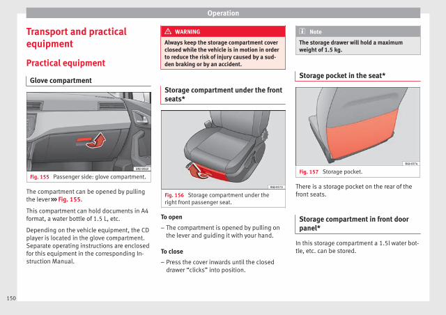
Operation
Transport and practicalequipment
Practical equipment
Glove compartment
Fig. 155 Passenger side: glove compartment.
The compartment can be opened by pullingthe lever ››› Fig. 155.
This compartment can hold documents in A4format, a water bottle of 1.5 L, etc.
Depending on the vehicle equipment, the CDplayer is located in the glove compartment.Separate operating instructions are enclosedfor this equipment in the corresponding In-struction Manual.
WARNING
Always keep the storage compartment coverclosed while the vehicle is in motion in orderto reduce the risk of injury caused by a sud-den braking or by an accident.
Storage compartment under the frontseats*
Fig. 156 Storage compartment under theright front passenger seat.
To open
– The compartment is opened by pulling onthe lever and guiding it with your hand.
To close
– Press the cover inwards until the closeddrawer “clicks” into position.
Note
The storage drawer will hold a maximumweight of 1.5 kg.
Storage pocket in the seat*
Fig. 157 Storage pocket.
There is a storage pocket on the rear of thefront seats.
Storage compartment in front doorpanel*
In this storage compartment a 1.5l water bot-tle, etc. can be stored.
150
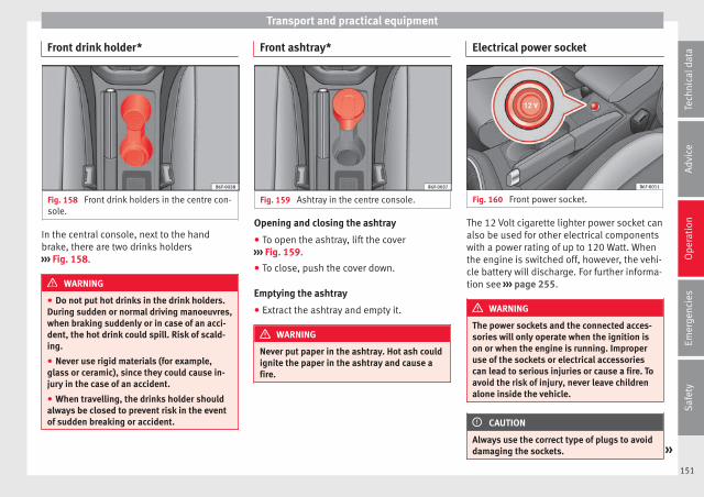
Transport and practical equipment
Front drink holder*
Fig. 158 Front drink holders in the centre con-sole.
In the central console, next to the handbrake, there are two drinks holders››› Fig. 158.
WARNING
● Do not put hot drinks in the drink holders.During sudden or normal driving manoeuvres,when braking suddenly or in case of an acci-dent, the hot drink could spill. Risk of scald-ing.
● Never use rigid materials (for example,glass or ceramic), since they could cause in-jury in the case of an accident.
● When travelling, the drinks holder shouldalways be closed to prevent risk in the eventof sudden breaking or accident.
Front ashtray*
Fig. 159 Ashtray in the centre console.
Opening and closing the ashtray
● To open the ashtray, lift the cover››› Fig. 159.
● To close, push the cover down.
Emptying the ashtray
● Extract the ashtray and empty it.
WARNING
Never put paper in the ashtray. Hot ash couldignite the paper in the ashtray and cause afire.
Electrical power socket
Fig. 160 Front power socket.
The 12 Volt cigarette lighter power socket canalso be used for other electrical componentswith a power rating of up to 120 Watt. Whenthe engine is switched off, however, the vehi-cle battery will discharge. For further informa-tion see ››› page 255.
WARNING
The power sockets and the connected acces-sories will only operate when the ignition ison or when the engine is running. Improperuse of the sockets or electrical accessoriescan lead to serious injuries or cause a fire. Toavoid the risk of injury, never leave childrenalone inside the vehicle.
CAUTION
Always use the correct type of plugs to avoiddamaging the sockets. »
151
Tech
nica
l dat
aA
dvic
eO
pera
tion
Emer
genc
ies
Saf
ety
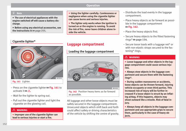
Operation
Note
● The use of electrical appliances with theengine switched off will cause a battery dis-charge.
● Before using any electrical accessories, seethe instructions in ››› page 255.
Cigarette lighter*
Fig. 161 Lighter.
– Press on the cigarette lighter ››› Fig. 161 toactivate it ››› .
– Wait for the lighter to spring out.
– Pull out the cigarette lighter and light thecigarette on the glowing coil.
WARNING
● Improper use of the cigarette lighter canlead to serious injuries or start a fire.
● Using the lighter carefully. Carelessness ornegligence when using the cigarette lightercan cause burns and serious injuries.
● The lighter only works when the ignition isturned on or the engine is running. To avoidthe risk of fire, never leave children alone in-side the vehicle.
Luggage compartment
Loading the luggage compartment
Fig. 162 Position heavy items as far forwardas possible.
All luggage and other loose objects must besafely secured in the luggage compartment.Unsecured objects which shift back and forthcould affect safety or driving characteristicsof the vehicle by shifting the centre of gravity.
– Distribute the load evenly in the luggagecompartment.
– Place heavy objects as far forward as possi-ble in the luggage compartment››› Fig. 162.
– Place the heavy objects first.
– Secure heavy objects to the fitted fasteningrings* ››› page 154.
– Secure loose loads with a luggage net* orwith non-elastic straps secured to the fas-tening* rings.
WARNING
● Loose luggage and other objects in the lug-gage compartment could cause serious inju-ries.
● Always stow objects in the luggage com-partment and secure them with the fasteningrings*.
● During sudden manoeuvres or accidents,loose objects can be thrown forward, injuringvehicle occupants or even third parties. Thisincreased risk of injury will be further in-creased if a loose object is struck by an inflat-ing airbag. If this happens, objects mayshoot outward like a missile. Risk of fatal in-jury.
● Always keep all objects in the luggage com-partment and use appropriate grips to securethem, particularly in the case of heavy ob-jects.
152
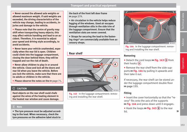
Transport and practical equipment
● Never exceed the allowed axle weights orallowed maximum weight. If said weights areexceeded, the driving characteristics of thevehicle may change, leading to accidents, in-juries and damage to the vehicle.
● Please note that the centre of gravity mayshift when transporting heavy objects; thismay affect vehicle handling and lead to an ac-cident. Therefore, it is essential to adjustyour speed and driving style accordingly, toavoid accidents.
● Never leave your vehicle unattended, espe-cially when the rear lid is open. Childrencould climb into the luggage compartment,closing the door behind them; they will betrapped and run the risk of death.
● Never allow children to play in or aroundthe vehicle. Close and lock all the doors andrear lid when you leave the vehicle. Beforeyou lock the vehicle, make sure that there areno adults or children in the vehicle.
● Please observe the notes on the ››› page 71.
CAUTION
Hard objects on the rear shelf could chafeagainst the wires of the heating element inthe heated rear window and cause damage.
Note
● The tyre pressure must be adjusted accord-ing to the load. When necessary, check thetyre pressures on the adhesive label stuck to
the back of the front left door frame››› page 279.
● Air circulation in the vehicle helps reducefogging of the windows. Used air escapesthrough ventilation slits in the side trim ofthe luggage compartment. Ensure that theventilation slots are never covered.
● Straps for securing the load to the fasten-ing rings* are commercially available from ac-cessory shops.
Rear shelf
Fig. 163 In the luggage compartment: remov-ing and installing the rear shelf.
Fig. 164 In the luggage compartment: remov-ing and installing the rear shelf.
Removing
● Detach the cord loops ››› Fig. 163 B fromtheir hooks A .
● Remove the rear shelf from the side sup-ports ››› Fig. 164 by pulling it upwards andthen take it out.
If necessary, the rear shelf can be stored un-der the luggage compartment double floor››› page 155.
Fitting
● Insert the cover horizontally so that the “re-cess” fits onto the axis of the supports››› Fig. 164 and press down until it engages.
● Hook the loops ››› Fig. 163 B to the rearlid. »
153
Tech
nica
l dat
aA
dvic
eO
pera
tion
Emer
genc
ies
Saf
ety

Operation
WARNING
Do not place heavy or hard objects on therear shelf, because they will endanger the ve-hicle occupants in case of sudden braking.
CAUTION
● Before closing the rear lid, ensure that therear shelf is correctly fitted.
● An overloaded luggage compartment couldmean that the rear shelf is not correctly seat-ed and it may be bent or damaged.
● If the luggage compartment is overloaded,remove the tray.
Note
● Ensure that, when placing items of clothingon the luggage compartment cover, rear visi-bility is not reduced.
Fastening rings*
Fig. 165 Location of fastening rings in lug-gage compartment.
There may be some fastening rings includedin the luggage compartment for fasteningluggage and other objects ››› Fig. 165 (ar-rows).
– Always use suitable and undamaged strapsto secure luggage and other objects to thefastening rings ››› in Loading the lug-gage compartment on page 152.
Example: An object weighing 4.5 kg is lyingunsecured in the vehicle. During a frontal col-lision at a speed of 50 km/h (31 mph), thisobject generates a force corresponding to 20times its weight. That means that the effec-tive weight of the object increases to approxi-mately 90 kg. You can imagine the severity ofthe injuries which might be sustained if this“object” strikes an occupant as it fliesthrough the interior of the vehicle. This in-
creased risk of injury will be further increasedif a loose object is struck by an inflating air-bag.
WARNING
● If pieces of baggage or other objects are se-cured to the fastening rings with inappropri-ate or damaged retaining cords, injuriescould result in the event of braking manoeu-vres or accidents.
● Never secure a child seat on the fasteningrings.
154

Transport and practical equipment
Luggage compartment variable floor
Fig. 166 Luggage compartment variablefloor: raised position; lowered position.
Fig. 167 Luggage compartment variablefloor: sloped position.
Variable floor in the high position
● Lift the floor using handle ››› Fig. 166 1
and pull it back until the front of the floor hasfully passed the supports 2 .
● Move the floor forward over the supports asfar as the rear seat backrest and then lowerthe floor with the handle 1 .
Variable floor in the low position
● Lift the floor using handle 1 and pull itback until the front of the floor has fullypassed the supports 2 .
● Now match the front part with the lowergrooves of the supports and slide the floorforwards as far as the rear seat backrest andlower the floor at the same time with the han-dle 1 .
Variable floor in the tilted position
When the variable floor is tilted you can ac-cess the spare wheel/anti-puncture kit area.
● Lift the variable floor using handle 1 , pullit up and push it towards the backrest of therear seats until the floor folds along thehinge line and the movable part of the flooris resting on itself.
● Rest the floor on its housings ››› Fig. 167(arrows).
WARNING
During a sudden driving or braking manoeu-vre, or in the event of an accident, objectscould be flung though the interior and causeserious or fatal injuries.
● Always secure objects, even when the lug-gage compartment floor is properly lifted.
● Only objects that do not protrude morethan 2/3 the height of the floor may be car-ried between the rear seat and the raised lug-gage compartment floor.
● Only objects that do not weigh than ap-proximately 7.5 kg may be carried betweenthe rear seat and the raised luggage compart-ment floor.
CAUTION
● The maximum weight that can be loaded onthe luggage compartment variable floor inthe top position is 150 kg. »
155
Tech
nica
l dat
aA
dvic
eO
pera
tion
Emer
genc
ies
Saf
ety
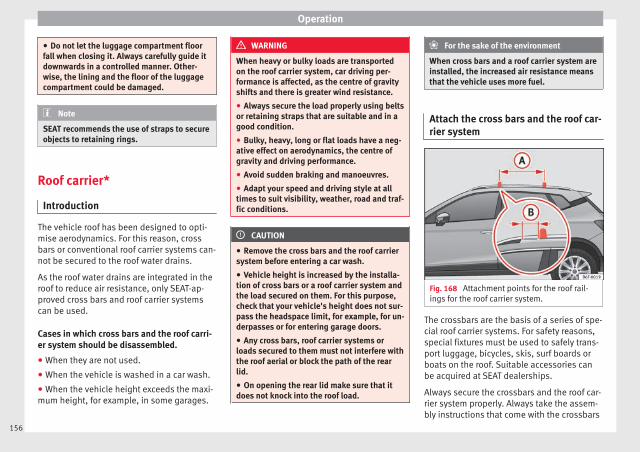
Operation
● Do not let the luggage compartment floorfall when closing it. Always carefully guide itdownwards in a controlled manner. Other-wise, the lining and the floor of the luggagecompartment could be damaged.
Note
SEAT recommends the use of straps to secureobjects to retaining rings.
Roof carrier*
Introduction
The vehicle roof has been designed to opti-mise aerodynamics. For this reason, crossbars or conventional roof carrier systems can-not be secured to the roof water drains.
As the roof water drains are integrated in theroof to reduce air resistance, only SEAT-ap-proved cross bars and roof carrier systemscan be used.
Cases in which cross bars and the roof carri-er system should be disassembled.
● When they are not used.
● When the vehicle is washed in a car wash.
● When the vehicle height exceeds the maxi-mum height, for example, in some garages.
WARNING
When heavy or bulky loads are transportedon the roof carrier system, car driving per-formance is affected, as the centre of gravityshifts and there is greater wind resistance.
● Always secure the load properly using beltsor retaining straps that are suitable and in agood condition.
● Bulky, heavy, long or flat loads have a neg-ative effect on aerodynamics, the centre ofgravity and driving performance.
● Avoid sudden braking and manoeuvres.
● Adapt your speed and driving style at alltimes to suit visibility, weather, road and traf-fic conditions.
CAUTION
● Remove the cross bars and the roof carriersystem before entering a car wash.
● Vehicle height is increased by the installa-tion of cross bars or a roof carrier system andthe load secured on them. For this purpose,check that your vehicle's height does not sur-pass the headspace limit, for example, for un-derpasses or for entering garage doors.
● Any cross bars, roof carrier systems orloads secured to them must not interfere withthe roof aerial or block the path of the rearlid.
● On opening the rear lid make sure that itdoes not knock into the roof load.
For the sake of the environment
When cross bars and a roof carrier system areinstalled, the increased air resistance meansthat the vehicle uses more fuel.
Attach the cross bars and the roof car-rier system
Fig. 168 Attachment points for the roof rail-ings for the roof carrier system.
The crossbars are the basis of a series of spe-cial roof carrier systems. For safety reasons,special fixtures must be used to safely trans-port luggage, bicycles, skis, surf boards orboats on the roof. Suitable accessories canbe acquired at SEAT dealerships.
Always secure the crossbars and the roof car-rier system properly. Always take the assem-bly instructions that come with the crossbars
156
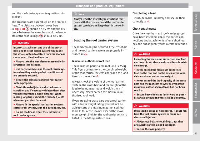
Transport and practical equipment
and the roof carrier system in question intoaccount.
The crossbars are assembled on the roof rail-ings. The distance between cross bars››› Fig. 168 A should be 75 cm and the dis-tance between the cross bars and the brack-ets of the roof railings B should be 5 cm.
WARNING
Incorrect attachment and use of the cross-bars and the roof carrier system may causethe whole system to detach from the roof andcause an accident and injuries.
● Always take the manufacturer assembly in-structions into account.
● Use only crossbars and the roof carrier sys-tem when they are in perfect condition andare properly secured.
● Secure the crossbars and the roof carriersystem properly.
● Check threaded joints and attachmentstravelling and if necessary tighten them afteryou have travelled a short distance. Whenmaking long trips, check the threaded jointswhenever you stop for a rest.
● Always fit the special roof carrier systemscorrectly for wheels, skis and surfboards, etc.
● Do not modify or repair the crossbars orroof carrier system.
Note
Always read the assembly instructions thatcome with the crossbars and the roof carriersystem carefully and keep them in the vehi-cle.
Loading the roof carrier system
The load can only be secured if the crossbarsand the roof carrier system are properly in-stalled ››› .
Maximum authorised roof load
The maximum permissible roof load is 75 kg.This figure comes from the combined weightof the roof carrier, the cross bars and the loaditself on the roof ››› .
Always check the weight of the roof carriersystem, the cross bars and the weight of theload to be transported and weigh them ifnecessary. Never exceed the maximum au-thorised roof load.
If you are using cross bars and a roof carrierwith a lower weight rating, you will not beable to carry the maximum authorised roofload. In this case, do not exceed the maxi-mum weight limit for the roof carrier which islisted in the fitting instructions.
Distributing a load
Distribute loads uniformly and secure themcorrectly ››› .
Check attachments
Once the cross bars and roof carrier systemhave been installed, check the bolted con-nections and attachments after a short jour-ney and subsequently with a certain frequen-cy.
WARNING
Exceeding the maximum authorised roof loadcan result in accidents and considerable vehi-cle damage.
● Never exceed the maximum authorisedload on the roof and on the axles or the vehi-cle's maximum authorised weight.
● Never exceed the load capacity of the crossbars and the roof carrier system, even if themaximum authorised roof load has not beenreached.
● Secure heavy items as far forward as possi-ble and distribute the vehicle load uniformly.
WARNING
If the load is loose or not secured, it could fallfrom the roof carrier system or cause acci-dents and injuries.
● Always use belts or retaining straps thatare suitable and in a good condition.
● Secure the load properly.
157
Tech
nica
l dat
aA
dvic
eO
pera
tion
Emer
genc
ies
Saf
ety
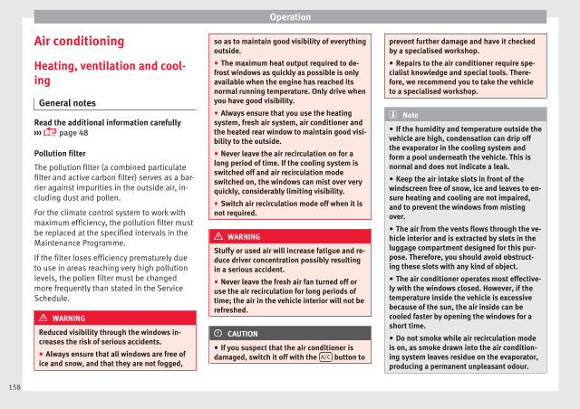
Operation
Air conditioning
Heating, ventilation and cool-ing
General notes
Read the additional information carefully››› page 48
Pollution filter
The pollution filter (a combined particulatefilter and active carbon filter) serves as a bar-rier against impurities in the outside air, in-cluding dust and pollen.
For the climate control system to work withmaximum efficiency, the pollution filter mustbe replaced at the specified intervals in theMaintenance Programme.
If the filter loses efficiency prematurely dueto use in areas reaching very high pollutionlevels, the pollen filter must be changedmore frequently than stated in the ServiceSchedule.
WARNING
Reduced visibility through the windows in-creases the risk of serious accidents.
● Always ensure that all windows are free ofice and snow, and that they are not fogged,
so as to maintain good visibility of everythingoutside.
● The maximum heat output required to de-frost windows as quickly as possible is onlyavailable when the engine has reached itsnormal running temperature. Only drive whenyou have good visibility.
● Always ensure that you use the heatingsystem, fresh air system, air conditioner andthe heated rear window to maintain good visi-bility to the outside.
● Never leave the air recirculation on for along period of time. If the cooling system isswitched off and air recirculation modeswitched on, the windows can mist over veryquickly, considerably limiting visibility.
● Switch air recirculation mode off when it isnot required.
WARNING
Stuffy or used air will increase fatigue and re-duce driver concentration possibly resultingin a serious accident.
● Never leave the fresh air fan turned off oruse the air recirculation for long periods oftime; the air in the vehicle interior will not berefreshed.
CAUTION
● If you suspect that the air conditioner isdamaged, switch it off with the A/C button to
prevent further damage and have it checkedby a specialised workshop.
● Repairs to the air conditioner require spe-cialist knowledge and special tools. There-fore, we recommend you to take the vehicleto a specialised workshop.
Note
● If the humidity and temperature outside thevehicle are high, condensation can drip offthe evaporator in the cooling system andform a pool underneath the vehicle. This isnormal and does not indicate a leak.
● Keep the air intake slots in front of thewindscreen free of snow, ice and leaves to en-sure heating and cooling are not impaired,and to prevent the windows from mistingover.
● The air from the vents flows through the ve-hicle interior and is extracted by slots in theluggage compartment designed for this pur-pose. Therefore, you should avoid obstruct-ing these slots with any kind of object.
● The air conditioner operates most effective-ly with the windows closed. However, if thetemperature inside the vehicle is excessivebecause of the sun, the air inside can becooled faster by opening the windows for ashort time.
● Do not smoke while air recirculation modeis on, as smoke drawn into the air condition-ing system leaves residue on the evaporator,producing a permanent unpleasant odour.
158
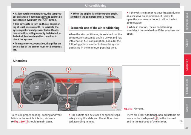
Air conditioning
● At low outside temperatures, the compres-sor switches off automatically and cannot beswitched on even with the AUTO button.
● It is advisable to turn on the air condition-ing at least once a month, to lubricate thesystem gaskets and prevent leaks. If a de-crease in the cooling capacity is detected, aTechnical Service should be consulted tocheck the system.
● To ensure correct operation, the grilles onboth sides of the screen must not be obstruc-ted.
● When the engine is under extreme strain,switch off the compressor for a moment.
Economic use of the air conditioning
When the air conditioning is switched on, thecompressor consumes engine power and hasinfluence on fuel consumption. Consider thefollowing points in order to have the systemoperating in the minimum possible time.
● If the vehicle interior has overheated due toan excessive solar radiation, it is best toopen the windows or doors to allow the hotair to escape.
● While in motion, the air conditioningshould not be switched on if the windows areopen.
Air outlets
Fig. 169 Air vents.
To ensure proper heating, cooling and venti-lation in the vehicle interior, air vents››› Fig. 169 1 should remain open.
● The outlets can be closed or opened sepa-rately using the slats and the air flow direc-ted according to need.
There are other additional, non-adjustable airvents in the dash panel 2 , in the footwelland in the rear area of the interior. »
159
Tech
nica
l dat
aA
dvic
eO
pera
tion
Emer
genc
ies
Saf
ety

Operation
Note
Food, medicine and other heat or cold sensi-tive objects should never be placed in front ofthe air outlets as they may be damaged ormade unsuitable for use by the air comingfrom the air vents.
Air recirculation
Air recirculation prevents unpleasant smells,e.g. when passing through a tunnel or inqueuing traffic, from entering the interior.
If the air distribution is in the thaw position,the recirculation flap will always be open (in-dicator light off).
If the air distribution is switched from any po-sition to the thaw position, recirculation willbe automatically deactivated.
Connecting the recirculation
In any air distribution position except thaw:
● Press button , the button’s lamp willlight up, indicating that air recirculation in-side the vehicle has been activated.
Disconnecting the recirculation
In any air distribution position except thaw:
● Press button again and the button'slamp will go off, indicating that air entry fromthe outside has been activated.
In the thaw position the entry of air intothe vehicle interior is always from the out-side.
WARNING
In air recirculation mode, no cold air from theoutside enters the vehicle interior. If the airconditioner is switched off, the windows can
quickly mist over. Therefore, never leave theair recirculation mode switched on for a longtime (risk of accident).
Note
● When engaging reverse gear, the air recir-culation is connected automatically to pre-vent the entrance of exhaust gases in the ve-hicle on travelling backwards. The controllamp on the button does not light up.
● If the temperature regulator is turned to thecoldest setting (blue point) and the buttonis on, the “Air recirculation” function is auto-matically activated in order to cool the vehi-cle faster using less energy, and its controllamp will light up.
● If the function is not deactivated by press-ing the button, it will deactivate after approx-imately 20 minutes.
160
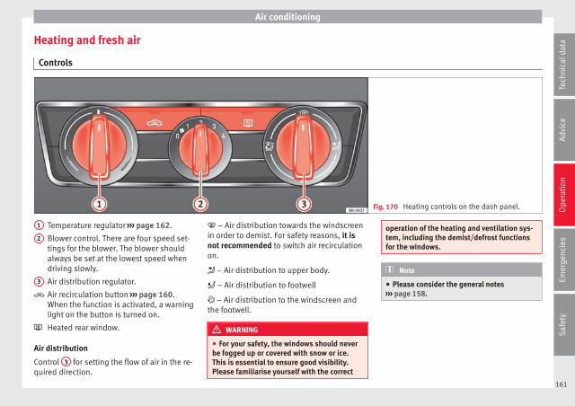
Air conditioning
Heating and fresh air
Controls
Fig. 170 Heating controls on the dash panel.
Temperature regulator ››› page 162.
Blower control. There are four speed set-tings for the blower. The blower shouldalways be set at the lowest speed whendriving slowly.
Air distribution regulator.
Air recirculation button ››› page 160.When the function is activated, a warninglight on the button is turned on.
Heated rear window.
Air distribution
Control 3 for setting the flow of air in the re-quired direction.
1
2
3
– Air distribution towards the windscreenin order to demist. For safety reasons, it isnot recommended to switch air recirculationon.
– Air distribution to upper body.
– Air distribution to footwell
– Air distribution to the windscreen andthe footwell.
WARNING
● For your safety, the windows should neverbe fogged up or covered with snow or ice.This is essential to ensure good visibility.Please familiarise yourself with the correct
operation of the heating and ventilation sys-tem, including the demist/defrost functionsfor the windows.
Note
● Please consider the general notes››› page 158.
161
Tech
nica
l dat
aA
dvic
eO
pera
tion
Emer
genc
ies
Saf
ety
Operation
Functions
Ventilating the vehicle interior
The desired temperature inside the vehiclecannot be lower than the ambient tempera-ture.
● Turn the temperature selector››› Fig. 170 1 anti-clockwise.
● Turn blower switch 2 to any of the levels1-4.
● Set the airflow to the desired direction us-ing air distribution control 3 .
● Open the relevant air outlets.
Interior heating
Maximum heat output, which is needed todefrost the windows quickly, is only availablewhen the engine has reached its operatingtemperature.
● Turn the temperature selector››› Fig. 170 1 clockwise to select the re-quired temperature.
● Turn blower switch 2 to any of the levels1-4.
● Set the airflow to the desired direction us-ing air distribution control 3 .
● Open the relevant air outlets.
Defrosting the windscreen
● Turn the temperature regulator››› Fig. 170 1 clockwise to reach the maxi-mum temperature.
● Turn the blower switch 2 to level 4.
● Turn air distribution control to .
● Close the central outlets.
● Open and turn the side outlets towards thewindows.
Keeping the windscreen and the side win-dows demisted
● Turn the temperature regulator››› Fig. 170 1 to the heating zone.
● Turn blower switch 2 to any of the levels2-3.
● Turn air distribution control to .
● Close the central outlets.
● Open and turn the side outlets towards thewindows.
Once the windows are demisted and as a pre-ventive measure, the control 3 can be set inposition greater comfort while preventingthe windows from misting again.
Note
Remember that the temperature of the enginecoolant should be optimum to ensure that theheating system functions correctly (except invehicles fitted with additional heating*).
162
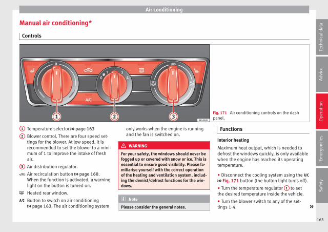
Air conditioning
Manual air conditioning*
Controls
Fig. 171 Air conditioning controls on the dashpanel.
Temperature selector ››› page 163
Blower control. There are four speed set-tings for the blower. At low speed, it isrecommended to set the blower to a mini-mum of 1 to improve the intake of freshair.
Air distribution regulator.
Air recirculation button ››› page 160.When the function is activated, a warninglight on the button is turned on.
Heated rear window.
Button to switch on air conditioning››› page 163. The air conditioning system
1
2
3
only works when the engine is runningand the fan is switched on.
WARNING
For your safety, the windows should never befogged up or covered with snow or ice. This isessential to ensure good visibility. Please fa-miliarise yourself with the correct operationof the heating and ventilation system, includ-ing the demist/defrost functions for the win-dows.
Note
Please consider the general notes.
Functions
Interior heating
Maximum heat output, which is needed todefrost the windows quickly, is only availablewhen the engine has reached its operatingtemperature.
● Disconnect the cooling system using the ››› Fig. 171 button (the button light turns off).
● Turn the temperature regulator 1 to setthe desired temperature inside the vehicle.
● Turn the blower switch to any of the set-tings 1-4. »
163
Tech
nica
l dat
aA
dvic
eO
pera
tion
Emer
genc
ies
Saf
ety

Operation
● Set the air distribution regulator 3 to theair flow configuration desired: (towardsthe windscreen), (towards the chest), (towards the footwell) and (towards thewindscreen and footwell areas).
Interior cooling
When the air conditioning is switched on, thetemperature and the air humidity go down.This way, if the outside humidity is extreme,the air conditioning prevents the misting ofthe windows and therefore, comfort is im-proved.
● Turn on the cooling system using the button (the button light turns on).
● Turn the temperature control switch untilthe desired interior temperature is reached.
● Turn the blower switch to any of the set-tings 1-4.
● Set the air distribution control to the airflow configuration desired: (towards thewindscreen), (towards the chest), (to-wards the footwell) and (towards the wind-screen and footwell areas).
Demisting the windscreen
● Turn air distribution to .
● Turn the fan control to one of the two levelsdepending on the speed required.
● Rotate the temperature control to the de-sired level of comfort.
● Close the central outlets.
● Open and turn the side outlets towards thewindows.
If the air conditioning does not work, thismay be due to the following reasons:
● The engine is stationary.
● The fan blower is switched off.
● The outside temperature is lower than ap-proximately +3°C (+37°F).
● The air conditioning system compressorhas been temporarily switched off because ofan increased engine coolant temperature.
● The air conditioner fuse is faulty.
● Another fault in the vehicle. Have the airconditioning checked by a specialised work-shop.
164
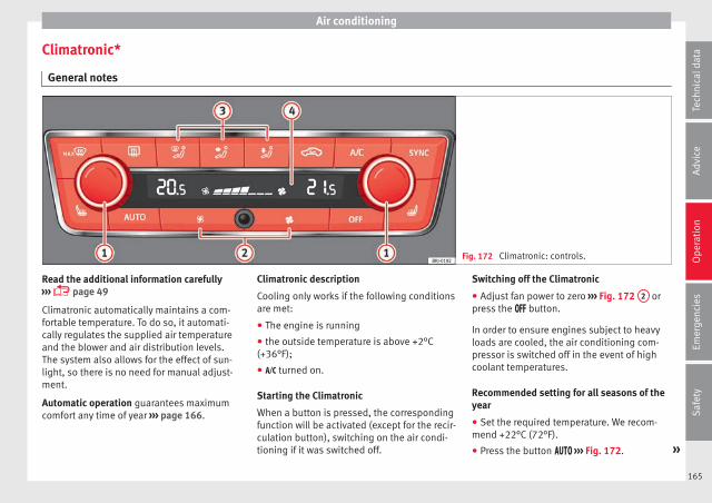
Air conditioning
Climatronic*
General notes
Fig. 172 Climatronic: controls.
Read the additional information carefully››› page 49
Climatronic automatically maintains a com-fortable temperature. To do so, it automati-cally regulates the supplied air temperatureand the blower and air distribution levels.The system also allows for the effect of sun-light, so there is no need for manual adjust-ment.
Automatic operation guarantees maximumcomfort any time of year ››› page 166.
Climatronic description
Cooling only works if the following conditionsare met:
● The engine is running
● the outside temperature is above +2°C(+36°F);
● turned on.
Starting the Climatronic
When a button is pressed, the correspondingfunction will be activated (except for the recir-culation button), switching on the air condi-tioning if it was switched off.
Switching off the Climatronic
● Adjust fan power to zero ››› Fig. 172 2 orpress the button.
In order to ensure engines subject to heavyloads are cooled, the air conditioning com-pressor is switched off in the event of highcoolant temperatures.
Recommended setting for all seasons of theyear
● Set the required temperature. We recom-mend +22°C (72°F).
● Press the button ››› Fig. 172. »
165
Tech
nica
l dat
aA
dvic
eO
pera
tion
Emer
genc
ies
Saf
ety

Operation
● Adjust the vents so that the air flow is di-rected slightly upwards.
Change between degrees Centigrade and de-grees Fahrenheit
Keep the and buttons held down for 2seconds at the same time. The data is dis-played on the screen in the units required.
Automatic mode
Automatic mode is used to maintain a con-stant temperature and demist the windowsinside the vehicle.
● Set the interior temperature between +16°C(+64°F) and +29°C (+84°F).
● Adjust the vents so that the air flow is di-rected slightly upwards.
● Press the button, AUTO is displayed onthe screen.
Automatic mode is switched off by pressingthe air distribution buttons or increasing ordecreasing the blower speed. However, thetemperature remains regulated.
Adjusting the temperature
● When you switch on the ignition, control 1
››› Fig. 172 can be used to set the required in-terior temperature.
It is possible to select interior temperaturesfrom +16°C (+64°F) to +29°C (+84°F). In this
range the temperature is regulated automati-cally. If a temperature below +16°C (+64°F) isselected, “LO” is displayed on the screen. If atemperature above +29°C (+84°F) is selected,“HI” is displayed on the screen. At both ex-tremes, Climatronic works at maximum cool-ing or heating power, respectively. The tem-perature is not regulated.
In the event of prolonged, irregular distribu-tion of the air flow from the outlets (particu-larly the footwells) and significant differen-ces in temperature, e.g. on leaving the vehi-cle, sensitive people may catch cold.
Fan regulation
Climatronic automatically regulates blowerspeed according to the interior temperature.It is possible, however, to set the blowerspeed to suit requirements.
● Press the 2 buttons to increase or reducefan speed.
Climatronic will switch off when the blowerswitches off.
Turn on windscreen defrost
● Press the button ››› Fig. 172.
Switching off windscreen defrosting
● Press the button several times orpress the button.
The temperature is regulated automatically.The air output from the vents ››› Fig. 169 2
is increased.
WARNING
Read and observe the safety warnings ››› inGeneral notes on page 158.
Note
● A visit to the specialised service once ayear is recommended to clean the Climatronicsystem.
● The interior temperature sensor is at thebottom. Do not cover it with stickers or thelike, as this could have a negative effect onClimatronic operations.
166
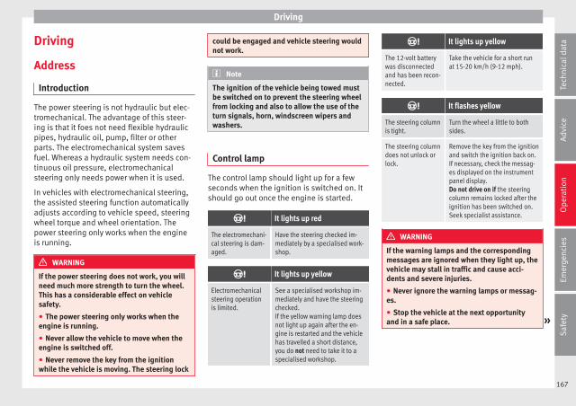
Driving
Driving
Address
Introduction
The power steering is not hydraulic but elec-tromechanical. The advantage of this steer-ing is that it foes not need flexible hydraulicpipes, hydraulic oil, pump, filter or otherparts. The electromechanical system savesfuel. Whereas a hydraulic system needs con-tinuous oil pressure, electromechanicalsteering only needs power when it is used.
In vehicles with electromechanical steering,the assisted steering function automaticallyadjusts according to vehicle speed, steeringwheel torque and wheel orientation. Thepower steering only works when the engineis running.
WARNING
If the power steering does not work, you willneed much more strength to turn the wheel.This has a considerable effect on vehiclesafety.
● The power steering only works when theengine is running.
● Never allow the vehicle to move when theengine is switched off.
● Never remove the key from the ignitionwhile the vehicle is moving. The steering lock
could be engaged and vehicle steering wouldnot work.
Note
The ignition of the vehicle being towed mustbe switched on to prevent the steering wheelfrom locking and also to allow the use of theturn signals, horn, windscreen wipers andwashers.
Control lamp
The control lamp should light up for a fewseconds when the ignition is switched on. Itshould go out once the engine is started.
It lights up red
The electromechani-cal steering is dam-aged.
Have the steering checked im-mediately by a specialised work-shop.
It lights up yellow
Electromechanicalsteering operationis limited.
See a specialised workshop im-mediately and have the steeringchecked.If the yellow warning lamp doesnot light up again after the en-gine is restarted and the vehiclehas travelled a short distance,you do not need to take it to aspecialised workshop.
It lights up yellow
The 12-volt batterywas disconnectedand has been recon-nected.
Take the vehicle for a short runat 15-20 km/h (9-12 mph).
It flashes yellow
The steering columnis tight.
Turn the wheel a little to bothsides.
The steering columndoes not unlock orlock.
Remove the key from the ignitionand switch the ignition back on.If necessary, check the messag-es displayed on the instrumentpanel display.Do not drive on if the steeringcolumn remains locked after theignition has been switched on.Seek specialist assistance.
WARNING
If the warning lamps and the correspondingmessages are ignored when they light up, thevehicle may stall in traffic and cause acci-dents and severe injuries.
● Never ignore the warning lamps or messag-es.
● Stop the vehicle at the next opportunityand in a safe place. »
167
Tech
nica
l dat
aA
dvic
eO
pera
tion
Emer
genc
ies
Saf
ety

Operation
Note
Failure to heed the control lamps and corre-sponding text messages when they light upmay result in damage to the vehicle.
Information relating to different vehi-cle processes.
In order to make the vehicle more difficult tosteal, you should always lock the steering be-fore leaving the vehicle.
Mechanical steering lock
The steering column is locked when the keyis removed from the ignition lock and the ve-hicle is stationary.
Activating the steering lock
● Park the vehicle ››› page 174.
● Remove the ignition key.
● Turn the steering wheel slightly until thesteering lock has engaged.
Deactivating the steering lock
● Turn the steering wheel slightly to releasethe lock.
● Insert the key in the ignition lock.
● Hold the steering wheel in this positionand switch on the ignition.
Electromechanical steering
In vehicles with electromechanical steering,the assisted steering function automaticallyadjusts according to vehicle speed, steeringwheel torque and wheel orientation. Thepower steering only works when the engineis running.
You should take into account that you willneed considerably more power than normalto steer the vehicle if the power steering isnot working correctly or at all.
Power-assisted steering
Power-assisted steering helps the driver incritical situations. In counter-steering, it as-sists by applying additional torque ››› .
WARNING
Power-assisted steering, together with theESC, helps the driver to control vehicle steer-ing in critical situations. However, the driveris ultimately responsible for steering the ve-hicle at all times. Power-assisted steeringdoes not remove this responsibility.
Starting and stopping the en-gine
Ignition key positions
Fig. 173 Ignition key positions.
Read the additional information carefully››› page 30
Ignition switched off, steering lock 1
In this position ››› Fig. 173, the ignition andthe engine are OFF and the steering may belocked.
For the Steering lock to operate without theignition key, turn the steering wheel until itlocks with an audible sound. You should al-ways lock the steering wheel when you leaveyour vehicle. This will help prevent vehicletheft ››› .
168

Driving
Switching the ignition or the glow plug sys-tem on 2
Turn the ignition key to this position and re-lease it. If the key cannot be turned or it isdifficult to turn from position 1 to position
2 , move the steering wheel from one side tothe other; this will release it.
Starting 3
The engine is started when the key is in thisposition. Electrical devices with high powerconsumption are switched off temporarily atthe same time.
Each time that the vehicle is restarted, the ig-nition key must be turned to position 1 . Therepetitive start prevention lock of the igni-tion prevents possible damage to the startermotor if the engine is already running.
WARNING
● The ignition key must NOT be removed fromthe lock until the vehicle comes to a stand-still. Otherwise, the steering could be imme-diately blocked- Risk of accident!
● Always remove the key from the ignitionwhen leaving the vehicle, even if only for ashort period. This is especially important ifchildren or disabled people are left alone inthe vehicle. They could accidentally start theengine or work electrical equipment such asthe electric windows, resulting in an acci-dent.
● Unsupervised use of the key could start theengine or any electrical system, such as theelectric windows. This could result in seriousinjury.
CAUTION
The starter motor will only work when the en-gine is stopped (ignition key position 3 ).
Electronic immobiliser “SAFE”
The electronic immobiliser prevents unau-thorised persons from driving the vehicle.
Inside the key there is a chip that deactivatesthe electronic immobiliser automaticallywhen the key is inserted into the ignition.
The electronic immobiliser will be activatedagain automatically as soon as you pull thekey out of the ignition lock.
The engine can only be started using a genu-ine SEAT key with its correct code.
If the following message* is shown on the in-strument panel display: SAFE, the vehiclecannot be started.
The engine can, however, be started if theappropriate coded SEAT genuine key is used.
Note
A perfect operation of the vehicle is ensuredif genuine SEAT keys are used.
Starting petrol engines
The engine can only be started using a genu-ine SEAT key with its correct code.
– Move the gearbox lever to the neutral posi-tion and depress the clutch pedal thor-oughly and hold it in this position for thestarter to turn the engine on.
– Turn the ignition key to the starting posi-tion ››› page 168.
– Let go of the ignition key as soon as the en-gine starts; the starter motor must not runon with the engine.
After starting a very hot engine, you mayneed to slightly press down the accelerator.
When starting a cold engine, it may be a littlenoisy for the first few seconds until oil pres-sure has built up in the hydraulic valve com-pensators. This is quite normal, and no causefor concern.
If the engine does not start immediately,switch the starter off after 10 seconds and tryagain after half a minute. If the engine stilldoes not start, the fuel pump fuse should bechecked ››› page 100, Fuses. »
169
Tech
nica
l dat
aA
dvic
eO
pera
tion
Emer
genc
ies
Saf
ety
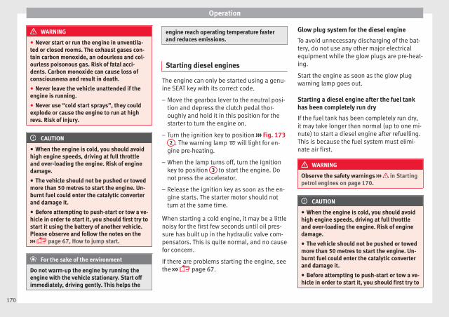
Operation
WARNING
● Never start or run the engine in unventila-ted or closed rooms. The exhaust gases con-tain carbon monoxide, an odourless and col-ourless poisonous gas. Risk of fatal acci-dents. Carbon monoxide can cause loss ofconsciousness and result in death.
● Never leave the vehicle unattended if theengine is running.
● Never use “cold start sprays”, they couldexplode or cause the engine to run at highrevs. Risk of injury.
CAUTION
● When the engine is cold, you should avoidhigh engine speeds, driving at full throttleand over-loading the engine. Risk of enginedamage.
● The vehicle should not be pushed or towedmore than 50 metres to start the engine. Un-burnt fuel could enter the catalytic converterand damage it.
● Before attempting to push-start or tow a ve-hicle in order to start it, you should first try tostart it using the battery of another vehicle.Please observe and follow the notes on the››› page 67, How to jump start.
For the sake of the environment
Do not warm-up the engine by running theengine with the vehicle stationary. Start offimmediately, driving gently. This helps the
engine reach operating temperature fasterand reduces emissions.
Starting diesel engines
The engine can only be started using a genu-ine SEAT key with its correct code.
– Move the gearbox lever to the neutral posi-tion and depress the clutch pedal thor-oughly and hold it in this position for thestarter to turn the engine on.
– Turn the ignition key to position ››› Fig. 1732 . The warning lamp will light for en-
gine pre-heating.
– When the lamp turns off, turn the ignitionkey to position 3 to start the engine. Donot press the accelerator.
– Release the ignition key as soon as the en-gine starts. The starter motor should notturn at the same time.
When starting a cold engine, it may be a littlenoisy for the first few seconds until oil pres-sure has built up in the hydraulic valve com-pensators. This is quite normal, and no causefor concern.
If there are problems starting the engine, seethe ››› page 67.
Glow plug system for the diesel engine
To avoid unnecessary discharging of the bat-tery, do not use any other major electricalequipment while the glow plugs are pre-heat-ing.
Start the engine as soon as the glow plugwarning lamp goes out.
Starting a diesel engine after the fuel tankhas been completely run dry
If the fuel tank has been completely run dry,it may take longer than normal (up to one mi-nute) to start a diesel engine after refuelling.This is because the fuel system must elimi-nate air first.
WARNING
Observe the safety warnings ››› in Startingpetrol engines on page 170.
CAUTION
● When the engine is cold, you should avoidhigh engine speeds, driving at full throttleand over-loading the engine. Risk of enginedamage.
● The vehicle should not be pushed or towedmore than 50 metres to start the engine. Un-burnt fuel could enter the catalytic converterand damage it.
● Before attempting to push-start or tow a ve-hicle in order to start it, you should first try to
170
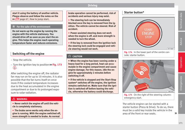
Driving
start it using the battery of another vehicle.Please observe and follow the notes on the››› page 67, How to jump start.
For the sake of the environment
Do not warm-up the engine by running theengine with the vehicle stationary. Youshould drive off as soon as you start the en-gine. This helps the engine reach operatingtemperature faster and reduces emissions.
Switching off the engine
– Stop the vehicle.
– Turn the ignition key to position ››› Fig. 1731 .
After switching the engine off, the radiatorfan may run on for up to 10 minutes. It is alsopossible that the fan turns itself on oncemore if the coolant temperature increasesdue to the heat accumulated in the enginecompartment or due to its prolonged expo-sure to solar radiation.
WARNING
● Never switch the engine off until the vehi-cle is completely stationary.
● The brake servo works only when the en-gine is running. With the engine switched off,more strength is needed to brake. As normal
brake operation cannot be performed, risk ofaccidents and serious injury may exist.
● The steering lock can be immediatelyblocked once the key is removed from the ig-nition. The vehicle cannot be steered. Risk ofaccident.
● Power-assisted steering does not workwhen the engine is off, and more strength isneeded to turn the wheel.
● If the key is removed from the ignition lockthe steering lock could be engaged and vehi-cle steering would not work.
CAUTION
● When the engine has been running under aheavy load for a long period, heat can accu-mulate in the engine compartment and causeengine damage. For this reason, idle the en-gine for approximately 2 minutes beforeswitching it off.
● If the vehicle is stopped and the Start-Stopsystem* switches off the engine, the ignitionremains switched on. Make sure that the igni-tion is switched off before leaving the vehi-cle, otherwise the battery could discharge.
Starter button*
Fig. 174 In the lower part of the centre con-sole: starter button.
Fig. 175 On the right of the steering column:emergency start.
The vehicle engine can be started with astarter button (Press & Drive). To do so, theremust be a valid key inside the vehicle in thearea of the front or rear seats. »
171
Tech
nica
l dat
aA
dvic
eO
pera
tion
Emer
genc
ies
Saf
ety

Operation
Opening the driver's door when exiting thevehicle activates the electronic lock on thesteering column if the ignition is disabled.
Switching the ignition on/off manually
Briefly push the starter button without touch-ing the brake or clutch pedal ››› .
For vehicles with both manual and automatictransmission, the starter button textSTART ENGINE STOP flashes like a heartbeat
when the system is preset for switching theignition on and off.
Automatic ignition switch-off
If the driver leaves the vehicle, taking the ve-hicle key with them but leaving the ignitionon, the ignition is not switched off automati-cally. The ignition is switched off automati-cally by pressing the lock button on the re-mote control or manually by pressing thesensor surface on the door lever ››› Fig. 141
Emergency starting function
If no valid key is detected inside the vehicle,an emergency start-up will be required. Therelevant message will appear in the dashpanel display. This may happen when, for ex-ample, the battery of the vehicle key buttonis very low or flat:
● Immediately after pushing the starter but-ton, keep the vehicle key next to the right
trim of the steering column ››› Fig. 175, asclose as possible to the Kessy logo.
● The ignition connects and the engine startsautomatically.
Emergency disconnection
If the engine does not switch off after brieflypressing the starter button, an emergencydisconnect will be required:
● Press the starter button twice within 3 sec-onds or press it once for more than 1 sec-ond ››› .
● The engine turns off automatically.
Engine restart feature
If no valid key is detected inside the vehicleafter the engine stops, you will only have 5seconds to restart it. A warning will displayon the dash panel screen.
After this interval, it will not be possible tostart the engine without a valid key insidethe vehicle.
Automatic deactivation of the ignition on ve-hicles with the Start-Stop system
The ignition is switched off automaticallywhen the vehicle is stopped and the auto-matic engine shutdown is active, if:
● The driver's seat belt is not fastened,
● the driver does not step on any pedal,
● the driver door is opened.
After automatically turning off the ignition, ifthe dipped beam is on, the side light re-mains on for approx. 30 minutes (if the bat-tery is sufficiently charged). If the driver locksthe vehicle or manually turns off the light, theside light goes out.
WARNING
Any accidental movement of the vehicle couldresult in serious injury.
● When switching on the ignition, do notpress the brake or clutch pedal, otherwisethe engine could start immediately.
WARNING
If vehicle keys are used negligently or with-out due care, this may cause accidents andserious injury.
● Never leave any key inside the vehiclewhen exiting. Otherwise, a child or unauthor-ised person could lock the vehicle, start theengine or connect the ignition and, in thisway, operate electronic equipment (e.g. thewindows).
Note
● Before leaving the vehicle, always discon-nect the ignition manually and, if appropri-ate, take into account the instructions on thescreen of the dash panel.
172
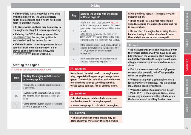
Driving
● If the vehicle is stationary for a long timewith the ignition on, the vehicle batterymight be discharged and it might not be pos-sible to start the engine.
● In diesel vehicles, there may be a delay inthe engine starting if it requires preheating.
● If during the STOP phase you press theSTART ENGINE STOP button, the ignition is
switched off and the button flashes.
● If the indication “Start-Stop system deacti-vated: Start the engine manually” is dis-played on the dash panel display, theSTART ENGINE STOP button will blink.
Starting the engine3 Valid for vehicles: with starter button
StepStarting the engine with the starterbutton ››› page 171.
1.Press and hold the brake pedal until step 5is performed.
1a.In vehicles with a manual gearbox: pressand hold the clutch down until the enginestarts.
2.Put the gearbox lever in neutral or the selec-tor lever in position P or N.
StepStarting the engine with the starterbutton ››› page 171.
3.
Briefly press the starter button ››› Fig. 174without pressing the accelerator. For the en-gine to start there must be a valid key in thevehicle.After starting the engine, the light of theSTART ENGINE STOP button changes to a fixed
light indicating that the engine has started.
4.
If the engine does not start, stop and wait forapprox. 1 minute before trying again. If nec-essary, perform an emergency start››› page 172.
5.Disconnect the hand brake when you areabout to start driving ››› page 174.
WARNING
Never leave the vehicle with the engine run-ning, especially if a gear or gear range is en-gaged. The vehicle could then suddenly moveor something strange could happen thatwould cause damage, fire or serious injury.
WARNING
Cold start sprays could explode or cause asudden increase in the engine speed.
● Never use sprays to cold start the engine.
CAUTION
● The starter motor or the engine may bedamaged if you try to start the engine while
driving or if you restart it immediately afterswitching it off.
● If the engine is cold, avoid high enginespeeds, pushing the engine too hard and rap-id acceleration.
● Do not start the engine by pushing the ve-hicle or towing it. Unburnt fuel could enterthe catalytic converter and damage it.
Note
● Do not wait until the engine warms up withthe vehicle stationary; if you have good visi-bility through the windows, start driving im-mediately. This helps the engine reach oper-ating temperature faster and reduces emis-sions.
● Electrical components with a high powerconsumption are switched off temporarilywhen the engine starts.
● When starting with a cold engine, noiselevels may briefly increase. This is quite nor-mal, and no cause for concern.
● When the outside temperature is below+5°C (+41°F), if the engine is diesel, somesmoke may appear under the vehicle whenthe fuel-operated auxiliary heater is on.
173
Tech
nica
l dat
aA
dvic
eO
pera
tion
Emer
genc
ies
Saf
ety
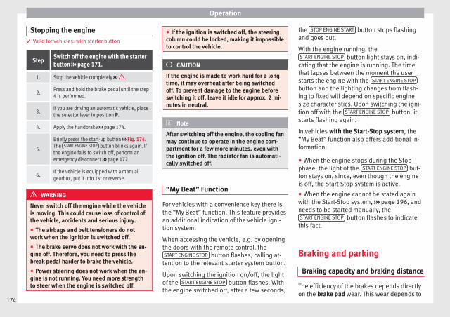
Operation
Stopping the engine3 Valid for vehicles: with starter button
StepSwitch off the engine with the starterbutton ››› page 171.
1. Stop the vehicle completely ››› .
2.Press and hold the brake pedal until the step4 is performed.
3.If you are driving an automatic vehicle, placethe selector lever in position P.
4. Apply the handbrake ››› page 174.
5.
Briefly press the start-up button ››› Fig. 174.The START ENGINE STOP button blinks again. Ifthe engine fails to switch off, perform anemergency disconnect ››› page 172.
6.If the vehicle is equipped with a manualgearbox, put it into 1st or reverse.
WARNING
Never switch off the engine while the vehicleis moving. This could cause loss of control ofthe vehicle, accidents and serious injury.
● The airbags and belt tensioners do notwork when the ignition is switched off.
● The brake servo does not work with the en-gine off. Therefore, you need to press thebreak pedal harder to brake the vehicle.
● Power steering does not work when the en-gine is not running. You need more strengthto steer when the engine is switched off.
● If the ignition is switched off, the steeringcolumn could be locked, making it impossibleto control the vehicle.
CAUTION
If the engine is made to work hard for a longtime, it may overheat after being switchedoff. To prevent damage to the engine beforeswitching it off, leave it idle for approx. 2 mi-nutes in neutral.
Note
After switching off the engine, the cooling fanmay continue to operate in the engine com-partment for a few more minutes, even withthe ignition off. The radiator fan is automati-cally switched off.
“My Beat” Function
For vehicles with a convenience key there isthe “My Beat” function. This feature providesan additional indication of the vehicle igni-tion system.
When accessing the vehicle, e.g. by openingthe doors with the remote control, theSTART ENGINE STOP button flashes, calling at-
tention to the relevant starter system button.
Upon switching the ignition on/off, the lightof the START ENGINE STOP button flashes. Withthe engine switched off, after a few seconds,
the STOP ENGINE START button stops flashingand goes out.
With the engine running, theSTART ENGINE STOP button light stays on, indi-
cating that the engine is running. The timethat lapses between the moment the userstarts the engine with the START ENGINE STOP
button and the lighting changes from flash-ing to fixed will depend on specific enginesize characteristics. Upon switching the igni-tion off with the START ENGINE STOP button, itstarts flashing again.
In vehicles with the Start-Stop system, the“My Beat” function also offers additional in-formation:
● When the engine stops during the Stopphase, the light of the START ENGINE STOP but-ton stays on, since, even though the engineis off, the Start-Stop system is active.
● When the engine cannot be stated againwith the Start-Stop system, ››› page 196, andneeds to be started manually, theSTART ENGINE STOP button flashes to indicate
this fact.
Braking and parking
Braking capacity and braking distance
The efficiency of the brakes depends directlyon the brake pad wear. This wear depends to
174

Driving
a great extent on the conditions under whichthe vehicle is operated and the way the vehi-cle is driven. If you often drive in town, driveshort distances or have a sporty driving style,we recommend that you have the thicknessof your brake pads checked by technical serv-ices more frequently than recommended inthe Maintenance Programme.
If you drive with wet brakes, for example, af-ter crossing areas of water, on days of heavyrainfall or even after washing the car, the ef-fect of the brakes is reduced as the brakediscs are wet or even frozen (in winter): inthis case, the brakes should be “dried” bypressing the brake pedal several times.
WARNING
Longer braking distances and faults in thebrake system increase the risk of accidents.
● New brake pads must be run in and do nothave the correct friction during the first200 km. This reduced braking capacity maybe compensated for by pressing on the brakepedal a little harder, which also applies whenthe brake pads have to be changed furtheron.
● If brakes are wet or frozen, or if you aredriving on roads which have been salted,braking power may be lower than normal.
● On steep slopes, if brakes are excessivelyused, they will overheat. Before driving downa long steep slope, it is advisable to reducespeed and change down into a lower gear or
range (depending on the type of transmis-sion). Thus, make use of engine braking andrelieve the brakes.
● Never let the brakes “drag” by applyinglight pressure. Continuous braking will causethe brakes to overheat and the braking dis-tance will increase. Apply and then releasethe brakes alternately.
● Never let the vehicle run with the engineswitched off. The braking distance is in-creased considerably when the brake servo isnot active.
● If the brake fluid loses its viscosity and issubjected to heavy use, vapour bubbles canform in the brake system. This reduces the ef-ficiency of the brakes.
● Non-standard or damaged front spoilerscould restrict the airflow to the brakes andcause them to overheat. Before purchasingaccessories please observe the relevant in-structions ››› page 255, Modifications.
● If a brake system circuit fails, the brakingdistance will be increased considerably. Con-tact a specialised workshop immediately andavoid unnecessary journeys.
Control lamp
Situations in which the warning lamp lightsup *
● the brake fluid level is too low››› page 275.
● there is a fault in the brake system.
This warning lamp can light up together withthe ABS system warning lamp.
WARNING
● If the brake warning lamp does not go outor if it lights up when driving, the brake fluidlevel in the reservoir is too low so there is arisk of an accident ››› page 275, Brake fluid.Stop the vehicle and do not drive on. Obtaintechnical assistance.
● If the brake warning lamp lights up to-gether with the ABS lamp this could bedue to an ABS fault. This could cause the rearwheels to lock quickly when you brake. Thiscould cause the rear to break away. Risk ofskidding. Stop the vehicle and seek technicalassistance.
Handbrake
Fig. 176 Handbrake between the front seats. »175
Tech
nica
l dat
aA
dvic
eO
pera
tion
Emer
genc
ies
Saf
ety
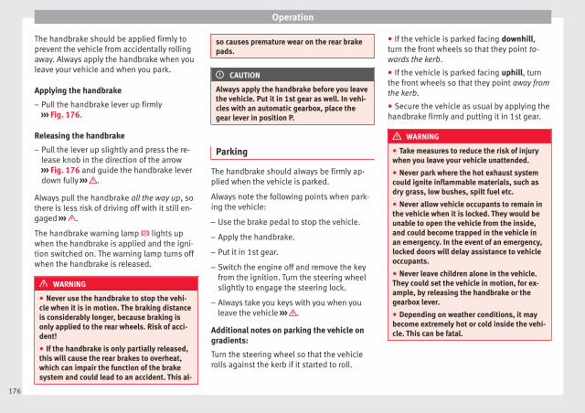
Operation
The handbrake should be applied firmly toprevent the vehicle from accidentally rollingaway. Always apply the handbrake when youleave your vehicle and when you park.
Applying the handbrake
– Pull the handbrake lever up firmly››› Fig. 176.
Releasing the handbrake
– Pull the lever up slightly and press the re-lease knob in the direction of the arrow››› Fig. 176 and guide the handbrake leverdown fully ››› .
Always pull the handbrake all the way up, sothere is less risk of driving off with it still en-gaged ››› .
The handbrake warning lamp lights upwhen the handbrake is applied and the igni-tion switched on. The warning lamp turns offwhen the handbrake is released.
WARNING
● Never use the handbrake to stop the vehi-cle when it is in motion. The braking distanceis considerably longer, because braking isonly applied to the rear wheels. Risk of acci-dent!
● If the handbrake is only partially released,this will cause the rear brakes to overheat,which can impair the function of the brakesystem and could lead to an accident. This al-
so causes premature wear on the rear brakepads.
CAUTION
Always apply the handbrake before you leavethe vehicle. Put it in 1st gear as well. In vehi-cles with an automatic gearbox, place thegear lever in position P.
Parking
The handbrake should always be firmly ap-plied when the vehicle is parked.
Always note the following points when park-ing the vehicle:
– Use the brake pedal to stop the vehicle.
– Apply the handbrake.
– Put it in 1st gear.
– Switch the engine off and remove the keyfrom the ignition. Turn the steering wheelslightly to engage the steering lock.
– Always take you keys with you when youleave the vehicle ››› .
Additional notes on parking the vehicle ongradients:
Turn the steering wheel so that the vehiclerolls against the kerb if it started to roll.
● If the vehicle is parked facing downhill,turn the front wheels so that they point to-wards the kerb.
● If the vehicle is parked facing uphill, turnthe front wheels so that they point away fromthe kerb.
● Secure the vehicle as usual by applying thehandbrake firmly and putting it in 1st gear.
WARNING
● Take measures to reduce the risk of injurywhen you leave your vehicle unattended.
● Never park where the hot exhaust systemcould ignite inflammable materials, such asdry grass, low bushes, spilt fuel etc.
● Never allow vehicle occupants to remain inthe vehicle when it is locked. They would beunable to open the vehicle from the inside,and could become trapped in the vehicle inan emergency. In the event of an emergency,locked doors will delay assistance to vehicleoccupants.
● Never leave children alone in the vehicle.They could set the vehicle in motion, for ex-ample, by releasing the handbrake or thegearbox lever.
● Depending on weather conditions, it maybecome extremely hot or cold inside the vehi-cle. This can be fatal.
176

Driving
Braking and stability systems
Electronic Stability Control (ESC)*
This Electronic Stability System reduces therisk of skidding and improves the vehicle'sstability and ability to hold the road.
The Electronic Stability Control (ESC) containsthe electronic differential lock (EDL) and thetraction control system (ASR). The ESC workstogether with the ABS. Both control lampswill light up if the ESC or ABS systems arefaulty.
The ESC system is started automaticallywhen the engine is started.
The ESC system is always active and cannotbe switched off. With the Easy Connect sys-tem it is only possible to deactivate the ASRor else select Sport mode.
The ASR can be deactivated when wheel spinis desirable ››› page 178.
For example:
● When driving with snow chains.
● When driving in deep snow or on loose sur-faces.
● When the vehicle is stuck, to rock it back-wards and forwards.
Press the button to switch the ASR back onwhen you no longer need wheel spin.
Electronic Stability Control (ESC)*
The ESC reduces the risk of skidding by brak-ing the wheels individually.
The system uses the steering wheel angleand road speed to calculate the changes ofdirection desired by the driver, and constant-ly compares them with the actual behaviourof the vehicle. When irregularities occur, forexample, if the vehicle begins to skid, theESC brakes the appropriate wheel automati-cally.
The forces acting on the braked wheel bringthe vehicle back to a stable condition. If thevehicle tends to oversteer (the rear endslides out), the system will act on the frontwheel on the outside of the turn.
Control lamp
There are two control lamps for the electronicstability control. The lamp provides infor-mation concerning function and disconnec-tion status.
Both control lamps light up together whenthe ignition is switched on and should turnoff after approximately 2 seconds. This is thetime taken for the function check.
This programme includes the ABS, EDL andASR. It also includes emergency braking as-sistance (BAS).
The control lamp has the following func-tions:
● It flashes whilst driving when the ASR/ESCis activated.
● It will light up if there is a fault in the ESC.
● As the ESC operates in conjunction with theABS, the ESC light will also come on if a faultshould occur in the ABS.
If the ESC control lamp lights up and stayson after the engine is started, this may meanthat the control system has temporarilyswitched off the ESC. In this case the ESC canbe reactivated by switching the ignition offand then on again. If the control lamp goesout, this means the system is fully functional.
The lamp provides information about thedisconnection status of the system:
● It stays lit when the ASR is disconnected orif you select ESC Sport mode, only by meansof Easy Connect.
WARNING
● Do not forget that the electronic stabilitycontrol ESC cannot defy the laws of physics.This should be kept in mind, particularly onslippery and wet roads and when towing atrailer.
● Always adapt your driving style to suit thecondition of the roads and the traffic situa-tion. The greater safety provided by the ESCshould not encourage you to run any risks. »
177
Tech
nica
l dat
aA
dvic
eO
pera
tion
Emer
genc
ies
Saf
ety

Operation
CAUTION
● To ensure that the ESC works correctly, allfour wheels must be fitted with the sametyres. Any differences in the rolling radius ofthe tyres can cause the system to reduce en-gine power when this is not desired.
● Any modifications made to the vehicle (forexample, to the engine, brake system, run-ning gear or to the combination of wheelsand tyres) may affect the operation of theABS, EDL, ESC and ASR.
Traction control system (ASR)
The traction control system prevents the driv-en wheels from spinning when the vehicle isaccelerating.
Description and operation of the tractioncontrol system during acceleration (ASR)
The ASR system intervenes by reducing en-gine power and preventing the driven wheelsfrom slipping during acceleration.
TCS helps the car to start moving, accelerateand climb a gradient in slippery conditionswhere this may otherwise be difficult or evenimpossible.
The ASR automatically switches on when theengine is started. If necessary, it could beswitched on or off using the Easy Connectsystem*.
When the ASR is off, the warning lamp lightsup . The ASR should normally be left on.Only in exceptional circumstances, whenwheel spin is required, it can be turned offusing the Easy Connect system menu, for ex-ample:
● With compact temporary spare wheel.
● When using the snow chains.
● When driving in deep snow or on soft ter-rain.
● When the vehicle is bogged-down, to free it“by rocking it.”
The ASR should be switched on again assoon as possible.
Control lamp
There are three control lamps for the tractioncontrol system: (for vehicles equippedwith M-ABS), (for vehicles equipped withESC) and . Both control lamps light up to-gether when the ignition is switched on andshould turn off after approximately 2 sec-onds, which is the time taken for the functioncheck.
The or lamp has the following function:
● It flashes when the ASR is working if the ve-hicle is moving.
If the system is deactivated or if it has anyfault, the warning lamp will remain lit. The
warning lamp will also light up if a faultshould occur in the ABS because the ASR op-erates in conjunction with the ABS. For fur-ther information, see ››› page 178.
The lamp provides information about thedisconnection status of the system:*
● It stays lit when the ASR is disconnectedvia Easy Connect.
By means of Easy Connect, the ASR functionis reactivated and the warning lamp switchedoff.
WARNING
● Remember that not even the ASR can defythe laws of physics. This should be kept inmind, particularly on slippery and wet roadsand when towing a trailer.
● Always adapt your driving style to suit thecondition of the roads and the traffic situa-tion. The greater safety provided by the ASRshould not encourage you to run any risks.
CAUTION
● To ensure that the ASR works correctly,identical tyres should be fitted on all fourwheels. Any differences in the rolling radiusof the tyres can cause the system to reduceengine power when this is not desired.
● Any modifications made to the vehicle (forexample, to the engine, brake system, run-ning gear or to the combination of wheels
178
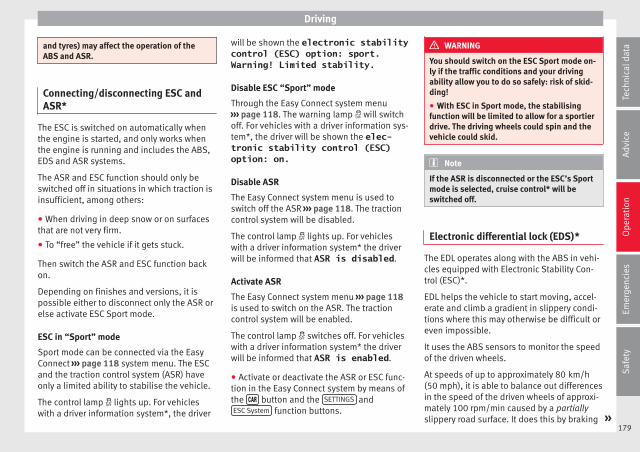
Driving
and tyres) may affect the operation of theABS and ASR.
Connecting/disconnecting ESC andASR*
The ESC is switched on automatically whenthe engine is started, and only works whenthe engine is running and includes the ABS,EDS and ASR systems.
The ASR and ESC function should only beswitched off in situations in which traction isinsufficient, among others:
● When driving in deep snow or on surfacesthat are not very firm.
● To “free” the vehicle if it gets stuck.
Then switch the ASR and ESC function backon.
Depending on finishes and versions, it ispossible either to disconnect only the ASR orelse activate ESC Sport mode.
ESC in “Sport” mode
Sport mode can be connected via the EasyConnect ››› page 118 system menu. The ESCand the traction control system (ASR) haveonly a limited ability to stabilise the vehicle.
The control lamp lights up. For vehicleswith a driver information system*, the driver
will be shown the electronic stabilitycontrol (ESC) option: sport.Warning! Limited stability.
Disable ESC “Sport” mode
Through the Easy Connect system menu››› page 118. The warning lamp will switchoff. For vehicles with a driver information sys-tem*, the driver will be shown the elec-tronic stability control (ESC)option: on.
Disable ASR
The Easy Connect system menu is used toswitch off the ASR ››› page 118. The tractioncontrol system will be disabled.
The control lamp lights up. For vehicleswith a driver information system* the driverwill be informed that ASR is disabled.
Activate ASR
The Easy Connect system menu ››› page 118is used to switch on the ASR. The tractioncontrol system will be enabled.
The control lamp switches off. For vehicleswith a driver information system* the driverwill be informed that ASR is enabled.
● Activate or deactivate the ASR or ESC func-tion in the Easy Connect system by means ofthe button and the SETTINGS andESC System function buttons.
WARNING
You should switch on the ESC Sport mode on-ly if the traffic conditions and your drivingability allow you to do so safely: risk of skid-ding!
● With ESC in Sport mode, the stabilisingfunction will be limited to allow for a sportierdrive. The driving wheels could spin and thevehicle could skid.
Note
If the ASR is disconnected or the ESC’s Sportmode is selected, cruise control* will beswitched off.
Electronic differential lock (EDS)*
The EDL operates along with the ABS in vehi-cles equipped with Electronic Stability Con-trol (ESC)*.
EDL helps the vehicle to start moving, accel-erate and climb a gradient in slippery condi-tions where this may otherwise be difficult oreven impossible.
It uses the ABS sensors to monitor the speedof the driven wheels.
At speeds of up to approximately 80 km/h(50 mph), it is able to balance out differencesin the speed of the driven wheels of approxi-mately 100 rpm/min caused by a partiallyslippery road surface. It does this by braking »
179
Tech
nica
l dat
aA
dvic
eO
pera
tion
Emer
genc
ies
Saf
ety
Operation
the wheel which has lost traction and distrib-uting more driving force to the other drivenwheel via the differential.
To prevent the disc brake of the brakingwheel from overheating, the EDL cuts out au-tomatically if subjected to excessive loads.The vehicle will continue to function normallywithout EDL. For this reason, the driver is notinformed that the EDL has been switched off.
The EDL will switch on again automaticallywhen the brake has cooled down.
Control lamp
A malfunction in the EDL is indicated by theESC control lamp . Take the vehicle to aspecialised workshop as soon as possible.
WARNING
● When accelerating on a slippery surface,for example on ice and snow, press the accel-erator carefully. Despite EDL, the drivenwheels may start to spin. This could impairthe vehicle's stability.
● Always adapt your driving style to suit roadconditions and the traffic situation. Do not letthe extra safety afforded by EDL tempt you in-to taking any risks when driving, this cancause accidents.
CAUTION
Modifications to the vehicle (e.g. to the en-gine, the brake system, running gear or any
components affecting the wheels and tyres)could affect the efficiency of the EDL››› page 255.
Hydraulic Brake Assist (HBA)*
The function (Hydraulic Brake Assist HBA) isonly included in vehicles with ESC.
In an emergency, most drivers brake in time,but not with maximum force. This results inunnecessarily long braking distances.
This is when the brake assist system comesinto action. When pressing the brake pedalrapidly, the assistant interprets it as an emer-gency. It very quickly builds up the full brakepressure so that the ABS can be activatedmore quickly and efficiently, thus reducingbraking distance.
Do not reduce the pressure on the brake ped-al, since the brake assist system switches offautomatically as soon as you release thebrake.
Automatic hazard warning lights activation
The brake lights flash automatically to indi-cate that the vehicle is braking suddenly or inan emergency situation. If the emergencybraking continues until the vehicle comes toa standstill, the hazard warning lights willthen come on and the brake lights will re-main on permanently from that moment. The
warning lights will automatically switch offwhen the vehicle begins to move again orwhen the "warning" light button is pressed.
WARNING
● The risk of accident is higher if you drivetoo fast, if you do not keep your distance fromthe vehicle in front, and when the road sur-face is slippery or wet. The increased acci-dent risk cannot be reduced by the brake as-sist system.
● The brake assist system cannot defy thelaws of physics. Slippery and wet roads aredangerous even with the brake assist system!Therefore, it is essential that you adjust yourspeed to suit the road and traffic conditions.Do not let the extra safety features tempt youinto taking any risks when driving.
Anti-lock brake system (ABS)
The anti-lock brake (ABS) system preventsthe wheels from locking during braking andis an important part of the vehicle's activesafety system.
How the ABS works
If one of the wheels turns too slowly in rela-tion to the vehicle's speed, and is close tolocking, the system will reduce the brakingpressure to this wheel. The driver is madeaware of this control process by a pulsatingof the brake pedal and audible noise. This is
180
Driving
a deliberate warning to the driver that one ormore of the wheels is tending to lock and theABS control function has intervened. In thissituation it is important to keep the brakepedal fully depressed so the ABS can regu-late the brake application. Do not “pump”.
If you brake hard on a slippery road surface,the best possible control is retained as thewheels do not lock.
However, ABS will not necessarily guaranteeshorter braking distances in all conditions.Braking distance could even be further if youbrake on gravel or on fresh snow on a slip-pery surface.
Control lamp
The control lamp lights up for a few sec-onds when the ignition is switched on. Itgoes out again after the system has runthrough an automatic test sequence.
There is a fault in the ABS if:
● The control lamp does not light up whenthe ignition is switched on.
● The control lamp does not go out again af-ter a few seconds.
● The control lamp lights up when the vehicleis moving.
The vehicle can still be braked in the normalway, without the ABS function. Take the vehi-
cle to a specialised workshop as soon aspossible.
If there is a fault in the ABS, the ESC* and thetyre pressure control lamp will also light up.
Brake system fault
If the ABS warning lamp lights up togetherwith the brake warning lamp , there is afault in the ABS function and in the brakesystem ››› .
WARNING
● The anti-lock brake system cannot defy thelaws of physics. Slippery and wet roads aredangerous even with ABS! If you notice thatthe ABS is working (to counteract lockedwheels under braking), you should reducespeed immediately to suit the road and trafficconditions. Do not let the extra safety fea-tures tempt you into taking any risks whendriving.
● The effectiveness of ABS is also determinedby the tyres fitted ››› page 278.
● If the running gear or brake system is modi-fied, the effectiveness of the ABS could be se-verely limited.
WARNING
● Before opening the bonnet, read and ob-serve the warnings ››› page 267, Working inthe engine compartment.
● If the brake system warning lamp shouldlight up together with the ABS warning lamp, stop the vehicle immediately and checkthe brake fluid level in the reservoir››› page 275, Brake fluid. If the brake fluidlevel has dropped below the “MIN” mark youmust not drive on. Risk of accident. Obtaintechnical assistance.
● If the brake fluid level is correct, the fault inthe brake system may have been caused by afailure of the ABS system. This could causethe rear wheels to lock quickly when youbrake. This could cause the rear to breakaway. Risk of skidding. Stop the vehicle andseek technical assistance.
Electronic differential lock (XDS)*
When taking a curve, the driveshaft differen-tial mechanism allows the outer wheel to turnat a higher speed than the inner wheel. Inthis way, the wheel that is turning faster (out-er wheel) receives less drive torque than theinner wheel. This may mean that in certainsituations the torque delivered to the innerwheel is too high, causing the wheels tospin. On the other hand, the outer wheel isreceiving a lower drive torque than it couldtransmit. This causes an overall loss of lateralgrip on the front axle, resulting in understeeror “lengthening” of the trajectory.
The XDS system can detect and correct thiseffect via the sensors and signals of the ESC. »
181
Tech
nica
l dat
aA
dvic
eO
pera
tion
Emer
genc
ies
Saf
ety

Operation
Via the ESC, the XDS will brake the insidewheel and counter the excess driving torqueof that wheel. This means that the driver'sdesired trajectory is much more precise.
The XDS system works in combination withthe ESC and is always active, even when ASRtraction control is disconnected or the ESC isin Sport mode.
Brake servo
The brake servo increases the pressure youapply to the brake pedal. It works only whenthe engine is running.
If the brake servo is not functioning, e.g. dueto a malfunction, or if the vehicle is beingtowed, you will have to press the brake pedalconsiderably harder to make up for the lackof servo assistance.
WARNING
The braking distance can also be affected byexternal factors.
● Never let the vehicle coast with the engineswitched off. Failure to follow this instructioncould result in an accident. The braking dis-tance is increased considerably when thebrake servo is not active.
● If the brake servo is not working, for exam-ple when the vehicle is being towed, you willhave to press the brake pedal considerablyharder than normal.
Hill driving assistant*
Fig. 177 Related video
This function is only included in vehicles withESC.
The hill driving assistant helps the driver tomove off and upward on a hill when the vehi-cle is stationary.
The system maintains brake pressure for ap-proximately two seconds after the drivertakes his foot off the brake pedal to preventthe vehicle from lurching backward when it isstarted. During these 2 seconds, the driverhas enough time to release the clutch pedaland accelerate without the vehicle movingand without having to use the handbrake,making start-up easier, more comfortableand safer.
These are the basic operation conditions:
● being on a ramp or hill/slope,
● doors closed,
● vehicle completely stationary,
● engine running and foot on the brake,
● besides having a gear engaged or being inneutral for manual gear change and with theselector lever at position S, D or R for an au-tomatic gearbox.
This system is also active when reversing up-hill.
WARNING
● If you do not start the vehicle immediatelyafter taking your foot off the brake pedal, thevehicle may start to roll back under certainconditions. Depress the brake pedal or usethe hand brake immediately.
● If the engine stalls, depress the brake ped-al or use the hand brake immediately.
● When following a line of traffic uphill, if youwant to prevent the vehicle from rolling backaccidentally when starting off, hold the brakepedal down for a few seconds before startingoff.
Note
The Official Service or a specialist workshopcan tell you if your vehicle is equipped withthis system.
182

Driving
Manual gearbox
Driving with manual gearbox
Read the additional information carefully››› page 47
Certain versions of the model may include a6-speed manual gearbox, and its diagram isshown on the gearbox lever.
The reverse gear can only be engaged whenthe car is stationary. When the engine is run-ning and before engaging this gear, waitabout 6 seconds with the clutch presseddown thoroughly in order to protect the gear-box.
The reverse lights switch on when the reversegear is selected and the ignition is on.
WARNING
● When the engine is running, the vehiclewill start to move as soon as a gear is engag-ed and the clutch released.
● Never select the reverse gear when the ve-hicle is in motion. Risk of accident.
Note
● Do not rest your hand on the gear leverwhile driving. The pressure of your handcould cause premature wear on the selectorforks in the gearbox.
● When changing gear, you should alwaysdepress the clutch fully to avoid unnecessarywear and damage.
● Do not “slip” the clutch to hold the vehicleon a hill. This causes premature wear anddamage to the clutch.
● Do not leave your foot on the clutch pedal;although the pressure may seem insignifi-cant, it can cause the premature wear of theclutch plate. Use the foot rest when you donot need to change gear.
Automatic gearbox/DSG auto-matic gearbox*
Introduction
Your vehicle is equipped with an electronical-ly controlled manual gearbox. Torque be-tween the engine and the gearbox is trans-mitted via two independent clutches. They re-place the torque converter found on conven-tional automatic gearboxes and allow forsmooth, uninterrupted acceleration of the ve-hicle.
The tiptronic system allows the driver tochange gears manually if desired››› page 185, Changing gears in tiptronicmode*.
Selector lever positions
Read the additional information carefully››› page 47
The selector lever position engaged is high-lighted on the display in the instrument clus-ter. With the selector lever in the manualgearbox positions G, D, E and S, the engagedgear is also indicated on the display.
P – Parking lock
When the selector lever is in this position,the driven wheels are locked mechanically.The parking lock must be engaged only whenthe vehicle is stationary ››› .
The interlock button (the button on the selec-tor lever handle) must be pressed in and si-multaneously the brake pedal must be de-pressed before moving the selector lever ei-ther in or out of position P.
R – Reverse gear
Reverse gear must be engaged only when thevehicle is stationary and the engine is idling››› .
To move the selector lever to position R, theinterlock button must be pressed in and atthe same time the brake pedal must be de-pressed. The reverse lights come on whenthe selector lever is in the R position with theignition on. »
183
Tech
nica
l dat
aA
dvic
eO
pera
tion
Emer
genc
ies
Saf
ety
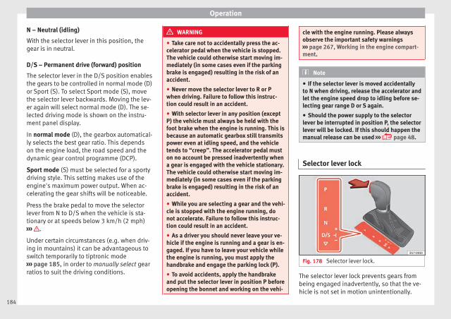
Operation
N – Neutral (idling)
With the selector lever in this position, thegear is in neutral.
D/S – Permanent drive (forward) position
The selector lever in the D/S position enablesthe gears to be controlled in normal mode (D)or Sport (S). To select Sport mode (S), movethe selector lever backwards. Moving the lev-er again will select normal mode (D). The se-lected driving mode is shown on the instru-ment panel display.
In normal mode (D), the gearbox automatical-ly selects the best gear ratio. This dependson the engine load, the road speed and thedynamic gear control programme (DCP).
Sport mode (S) must be selected for a sportydriving style. This setting makes use of theengine's maximum power output. When ac-celerating the gear shifts will be noticeable.
Press the brake pedal to move the selectorlever from N to D/S when the vehicle is sta-tionary or at speeds below 3 km/h (2 mph)››› .
Under certain circumstances (e.g. when driv-ing in mountains) it can be advantageous toswitch temporarily to tiptronic mode››› page 185, in order to manually select gearratios to suit the driving conditions.
WARNING
● Take care not to accidentally press the ac-celerator pedal when the vehicle is stopped.The vehicle could otherwise start moving im-mediately (in some cases even if the parkingbrake is engaged) resulting in the risk of anaccident.
● Never move the selector lever to R or Pwhen driving. Failure to follow this instruc-tion could result in an accident.
● With selector lever in any position (exceptP) the vehicle must always be held with thefoot brake when the engine is running. This isbecause an automatic gearbox still transmitspower even at idling speed, and the vehicletends to “creep”. The accelerator pedal muston no account be pressed inadvertently whena gear is engaged with the vehicle stationary.The vehicle could otherwise start moving im-mediately (in some cases even if the parkingbrake is engaged) resulting in the risk of anaccident.
● While you are selecting a gear and the vehi-cle is stopped with the engine running, donot accelerate. Failure to follow this instruc-tion could result in an accident.
● As a driver you should never leave your ve-hicle if the engine is running and a gear is en-gaged. If you have to leave your vehicle whilethe engine is running, you must apply thehandbrake and engage the parking lock (P).
● To avoid accidents, apply the handbrakeand put the selector lever in position P beforeopening the bonnet and working on the vehi-
cle with the engine running. Please alwaysobserve the important safety warnings››› page 267, Working in the engine compart-ment.
Note
● If the selector lever is moved accidentallyto N when driving, release the accelerator andlet the engine speed drop to idling before se-lecting gear range D or S again.
● Should the power supply to the selectorlever be interrupted in position P, the selectorlever will be locked. If this should happen themanual release can be used ››› page 48.
Selector lever lock
Fig. 178 Selector lever lock.
The selector lever lock prevents gears frombeing engaged inadvertently, so that the ve-hicle is not set in motion unintentionally.
184

Driving
The selector lever lock is released as follows:
– Switch the ignition on.
– Press the brake pedal and, at the sametime, hold the lock button in the directionof the arrow ››› Fig. 178.
Automatic selector lever lock
With the ignition switched on, the selectorlever is locked in the positions P and N. Thebrake pedal must be pressed to release thelever while pressing the release button if theselector lever is in the position P. As a re-minder for the driver, with the lever in posi-tions P or N the following message will beshown on the display:
When stationary, apply footbrakewhile selecting a gear.
Level lock only engages with the vehicle sta-tionary and at speeds of up to 5 km/h(3 mph). At speeds of over 5 km/h (3 mph)the lever lock is automatically deactivated inposition N.
The selector lever lock is not engaged if theselector lever is moved quickly through posi-tion N (e.g. when shifting from R to D). Thismakes it possible, for instance, to rock thevehicle “backwards and forwards” if it isstuck. The selector lever lock engages auto-matically if the brake pedal is not depressedand the lever is in position N for more thanabout two seconds.
Interlock button
The interlock button on the selector leverhandle prevents the driver from inadvertentlyengaging certain gears. Press the button into disengage the selector lever lock.
Safety interlock for ignition key
Once the ignition has been turned off, thekey may be removed only if the gear selectoris in position P. While the key is not in the ig-nition, the selector lever is locked in positionP.
Note
● If the selector lever lock does not engage,there is a fault. The transmission is interrup-ted to prevent the vehicle from accidentallymoving. Follow the procedure below in orderfor the selector lever lock to engage again:
– With a 6-speed gearbox: press the brakepedal and release it again.
– With a 7-speed gearbox: press the brakepedal. Move the selector lever to posi-tion P or N and subsequently engage agear.
● Despite a gear being engaged, the vehicledoes not move forwards or back. Proceed tothe next mode:
– When the vehicle does not move in therequired direction, the system may nothave the gear range correctly engaged.Press the brake pedal and engage thegear range again.
– If the vehicle still does not move in therequired direction, there is a system mal-function. Seek specialist assistance andhave the system checked.
Changing gears in tiptronic mode*
Fig. 179 Centre console: changing gear withtiptronic
Fig. 180 Steering wheel: automatic gearboxlevers »
185
Tech
nica
l dat
aA
dvic
eO
pera
tion
Emer
genc
ies
Saf
ety
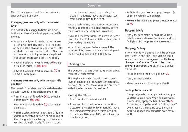
Operation
The tiptronic gives the driver the option tochange gears manually.
Changing gear manually with the selectorlever
It is possible to change to tiptronic mode,both when the vehicle is stopped and whiledriving.
– To switch to tiptronic mode, move the se-lector lever from position D/S to the right.As soon as the change is made the selectorlevel will be shown in the position M on theinstrument panel display (for example M4means that the fourth gear is engaged).
– Move the selector lever forwards + to se-lect a higher gear ››› Fig. 179.
– Move the selector lever backwards – toselect a lower gear.
Changing gear manually with the gearshiftpaddles*
The gearshift paddles can be used when theselector lever is in the position D/S or M.
– Press the gearshift paddle + to select ahigher gear ››› Fig. 180.
– Press the gearshift paddle – to select alower gear.
– With the selector lever in position D/S, if nopaddle is operated during a short period oftime, the gearbox control system switchesback to automatic mode. To switch to per-
manent manual gear change using thegearshift paddles, move the selector leverfrom position D/S to the right.
When accelerating, the gearbox automatical-ly shifts up into the next gear shortly beforethe maximum engine speed is reached.
If you select a lower gear, the automatic gear-box will not shift down until there is no risk ofover-revving the engine.
When the kick-down feature is used, thegearbox shifts down to a lower gear, depend-ing on road speed and engine speed.
Driving tips
The gearbox changes gear ratios automatical-ly as the vehicle moves.
The engine can only start with the selectorlever in position P or N. At low temperatures,below -10°C (50°F), the engine can only startwith the selector lever in position P.
Starting the vehicle
– Press and hold the brake pedal.
– Press and hold the interlock button (thebutton on the selector lever handle), movethe selector lever to the desired position,for instance D ››› page 183, and release theinterlock button.
– Wait for the gearbox to engage the gear (aslight movement can be felt).
– Release the brake and press the accelerator››› .
Stopping briefly
– Apply the foot brake to hold the vehiclebriefly when stationary (for instance at traf-fic lights). Do not press the accelerator.
Stopping/Parking
If the driver door is opened and the selectorlever is not in position P, the vehicle couldmove. The driver message will be: Gearchange: selector lever in thedrive position!. Additionally, a buzzerwill sound.
– Press and hold the brake pedal ››› .
– Apply the handbrake.
– Move the selector lever to position P.
Holding the car on a hill
– Always apply the brake pedal firmly to pre-vent the vehicle from “moving backwards;if necessary, apply the handbrake” ››› .Do not try to stop the vehicle “rolling back”by increasing the engine speed when agear is engaged (pressing the accelerator)››› .
186
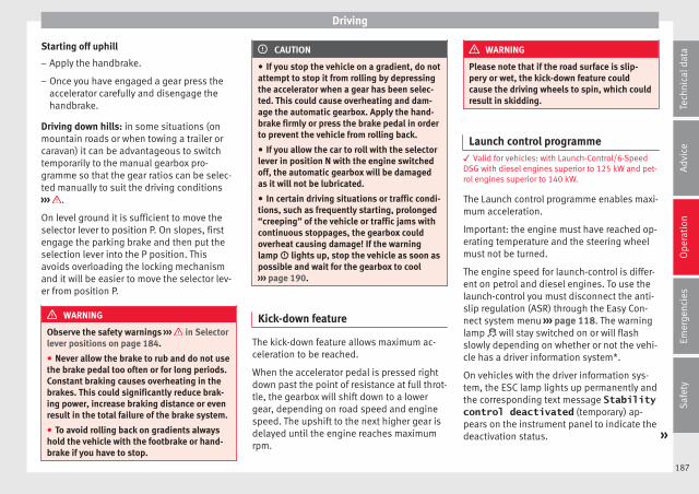
Driving
Starting off uphill
– Apply the handbrake.
– Once you have engaged a gear press theaccelerator carefully and disengage thehandbrake.
Driving down hills: in some situations (onmountain roads or when towing a trailer orcaravan) it can be advantageous to switchtemporarily to the manual gearbox pro-gramme so that the gear ratios can be selec-ted manually to suit the driving conditions››› .
On level ground it is sufficient to move theselector lever to position P. On slopes, firstengage the parking brake and then put theselection lever into the P position. Thisavoids overloading the locking mechanismand it will be easier to move the selector lev-er from position P.
WARNING
Observe the safety warnings ››› in Selectorlever positions on page 184.
● Never allow the brake to rub and do not usethe brake pedal too often or for long periods.Constant braking causes overheating in thebrakes. This could significantly reduce brak-ing power, increase braking distance or evenresult in the total failure of the brake system.
● To avoid rolling back on gradients alwayshold the vehicle with the footbrake or hand-brake if you have to stop.
CAUTION
● If you stop the vehicle on a gradient, do notattempt to stop it from rolling by depressingthe accelerator when a gear has been selec-ted. This could cause overheating and dam-age the automatic gearbox. Apply the hand-brake firmly or press the brake pedal in orderto prevent the vehicle from rolling back.
● If you allow the car to roll with the selectorlever in position N with the engine switchedoff, the automatic gearbox will be damagedas it will not be lubricated.
● In certain driving situations or traffic condi-tions, such as frequently starting, prolonged“creeping” of the vehicle or traffic jams withcontinuous stoppages, the gearbox couldoverheat causing damage! If the warninglamp lights up, stop the vehicle as soon aspossible and wait for the gearbox to cool››› page 190.
Kick-down feature
The kick-down feature allows maximum ac-celeration to be reached.
When the accelerator pedal is pressed rightdown past the point of resistance at full throt-tle, the gearbox will shift down to a lowergear, depending on road speed and enginespeed. The upshift to the next higher gear isdelayed until the engine reaches maximumrpm.
WARNING
Please note that if the road surface is slip-pery or wet, the kick-down feature couldcause the driving wheels to spin, which couldresult in skidding.
Launch control programme3 Valid for vehicles: with Launch-Control/6-SpeedDSG with diesel engines superior to 125 kW and pet-rol engines superior to 140 kW.
The Launch control programme enables maxi-mum acceleration.
Important: the engine must have reached op-erating temperature and the steering wheelmust not be turned.
The engine speed for launch-control is differ-ent on petrol and diesel engines. To use thelaunch-control you must disconnect the anti-slip regulation (ASR) through the Easy Con-nect system menu ››› page 118. The warninglamp will stay switched on or will flashslowly depending on whether or not the vehi-cle has a driver information system*.
On vehicles with the driver information sys-tem, the ESC lamp lights up permanently andthe corresponding text message Stabilitycontrol deactivated (temporary) ap-pears on the instrument panel to indicate thedeactivation status. »
187
Tech
nica
l dat
aA
dvic
eO
pera
tion
Emer
genc
ies
Saf
ety
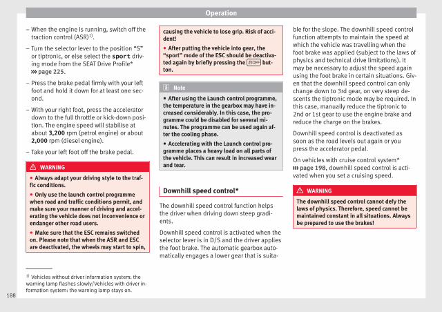
Operation
– When the engine is running, switch off thetraction control (ASR)1).
– Turn the selector lever to the position “S”or tiptronic, or else select the sport driv-ing mode from the SEAT Drive Profile*››› page 225.
– Press the brake pedal firmly with your leftfoot and hold it down for at least one sec-ond.
– With your right foot, press the acceleratordown to the full throttle or kick-down posi-tion. The engine speed will stabilise atabout 3,200 rpm (petrol engine) or about2,000 rpm (diesel engine).
– Take your left foot off the brake pedal.
WARNING
● Always adapt your driving style to the traf-fic conditions.
● Only use the launch control programmewhen road and traffic conditions permit, andmake sure your manner of driving and accel-erating the vehicle does not inconvenience orendanger other road users.
● Make sure that the ESC remains switchedon. Please note that when the ASR and ESCare deactivated, the wheels may start to spin,
causing the vehicle to lose grip. Risk of acci-dent!
● After putting the vehicle into gear, the“sport” mode of the ESC should be deactiva-ted again by briefly pressing the OFF but-ton.
Note
● After using the Launch control programme,the temperature in the gearbox may have in-creased considerably. In this case, the pro-gramme could be disabled for several mi-nutes. The programme can be used again af-ter the cooling phase.
● Accelerating with the Launch control pro-gramme places a heavy load on all parts ofthe vehicle. This can result in increased wearand tear.
Downhill speed control*
The downhill speed control function helpsthe driver when driving down steep gradi-ents.
Downhill speed control is activated when theselector lever is in D/S and the driver appliesthe foot brake. The automatic gearbox auto-matically engages a lower gear that is suita-
ble for the slope. The downhill speed controlfunction attempts to maintain the speed atwhich the vehicle was travelling when thefoot brake was applied (subject to the laws ofphysics and technical drive limitations). Itmay be necessary to adjust the speed againusing the foot brake in certain situations. Giv-en that the downhill speed control can onlychange down to 3rd gear, on very steep de-scents the tiptronic mode may be required. Inthis case, manually reduce the tiptronic to2nd or 1st gear to use the engine brake andreduce the charge on the brakes.
Downhill speed control is deactivated assoon as the road levels out again or youpress the accelerator pedal.
On vehicles with cruise control system*››› page 198, downhill speed control is acti-vated when you set a cruising speed.
WARNING
The downhill speed control cannot defy thelaws of physics. Therefore, speed cannot bemaintained constant in all situations. Alwaysbe prepared to use the brakes!
1) Vehicles without driver information system: thewarning lamp flashes slowly/Vehicles with driver in-formation system: the warning lamp stays on.
188

Driving
Inertia mode
The inertia mode enables the kinetic energyof the vehicle to be harnessed enabling cer-tain stretches to be driven without using theaccelerator. This enables fuel to be saved.Use the inertia mode to “let the vehicle roll”before, for example, arriving in a town.
Switching on inertia mode
Important: selector lever must be in positionD, gradients below 12 %.
– Select, in SEAT Drive Profile*, Eco mode››› page 225.
– Take your foot off the accelerator.
The driver message Inertia will be dis-played. At speeds higher than 20 km/h (12mph), the gearbox will automatically disen-gage and the vehicle will roll freely, withoutthe effect of the engine brake. While the vehi-cle rolls, the engine runs at idling speed.
Stopping inertia mode
– Press the brake or the accelerator pedal.
To make use of the braking force and switchoff the engine again, simply press the brakepedal briefly.
Applying both the inertia mode (= prolongedsection with less energy) and the switchingoff using inertia (= shorter section without
the need for fuel) facilitates improved fuelconsumption and emission balance.
WARNING
● If the inertia mode has been switched on,take into account, when approaching an ob-stacle and releasing the accelerator pedal,that the vehicle will not decelerate in the usu-al manner: risk of accident!
● When using inertia mode while travellingdown hills, the vehicle can increase speed:risk of accident!
● If other users drive your vehicle, warn themabout inertia mode.
Note
● Inertia mode is only available in eco (SEATDrive Profile*) driving mode.
● The driver message Inertia is only dis-played with the current consumption. In iner-tia mode the gear will no longer be displayed(for example “E” will appear instead of “E7”).
● On downhill sections with gradients above15 %, the inertia mode will automatically beswitched off temporarily.
Backup programme
A backup programme is in place if a faultshould occur in the control system.
If all the positions of the selector lever areshown over a light background on the instru-ment panel display, there is a system faultand the automatic gearbox will operate inwith the backup programme. When the back-up programme is activated, it is possible todrive the vehicle, however, at low speeds andwithin a selected range of gears. In some ca-ses driving in reverse gear may not be possi-ble.
CAUTION
If the gearbox operates with the backup pro-gramme, take the vehicle to a specialisedworkshop and have the fault repaired withoutdelay.
Clutch
Clutch overheating! Pleasestop!
The clutch has overheated and could be dam-aged. Stop the vehicle and wait for the gear-box to cool with the engine at idling speedand the selector lever in position P. When thewarning lamp and the driver message switchoff, have the fault corrected by a specialisedworkshop without delay. If the warning lampand the driver message do not switch off, donot continue driving. Seek specialist assis-tance.
189
Tech
nica
l dat
aA
dvic
eO
pera
tion
Emer
genc
ies
Saf
ety

Operation
Gearbox malfunctions
Gearbox: Fault! Stop the ve-hicle and place the lever in theposition P.
There is a fault in the gearbox. Stop the vehi-cle in a safe place and do not continue driv-ing. Seek specialist assistance.
Gearbox: System fault! Youmay continue driving.
Have the fault corrected by a specialisedworkshop without delay.
Gearbox: System fault! Youcan continue driving with re-strictions. Reverse gear disa‐bled
Take the vehicle to a specialised workshopand have the fault repaired without delay.
Gearbox: System fault! Youcan continue driving in D untilswitching off the engine
Stop the vehicle in a safe place well awayfrom moving traffic. Seek specialist assis-tance.
Gearbox: too hot. Adapt yourdriving accordingly
Continue driving at moderate speeds. Whenthe warning lamp switches off, you can con-tinue driving in a normal manner.
Gearbox: press the brake andengage a gear again.
If the fault was caused by a gearbox with ahigh temperature, this driver message will bedisplayed when the gearbox has cooledagain.
Gear-change indicator
Selecting the optimal gear
While driving, and depending on vehicleequipment, the instrument panel display mayshow a recommendation with the gear num-ber that would be advisable to save fuel.
In vehicles with an automatic gearbox, theselector lever must be in the Tiptronic posi-tion ››› page 185.
No recommendation will appear if the opti-mal gear is already engaged. The currentgear will be displayed.
Display Meaning
The optimal gear is selected.
Changing to a higher gear is recom-mended.
Changing to a lower gear is recom-mended.
Information regarding the “cleanliness” ofthe diesel particulate filter
The exhaust system manager detects that thediesel particulate filter is nearly saturatedand contributes to self-cleaning by recom-mending the optimal gear. For this reason, itmight be necessary to drive for a short timeat a high rpm.
WARNING
The gear change indicator is only an auxiliaryfunction and in no case should be a substi-tute for careful driving.
● The responsibility of choosing the correctgear depending on the situation (e.g. over-taking, driving up or down a slope or towing atrailer) lies with the driver.
For the sake of the environment
Selecting the correct gear can help to savefuel.
Note
The recommended gear indication turns offwhen the clutch pedal is pressed in vehicleswith manual gearbox or when the selectorlever is removed from the Tiptronic positionin vehicles with an automatic gearbox.
190
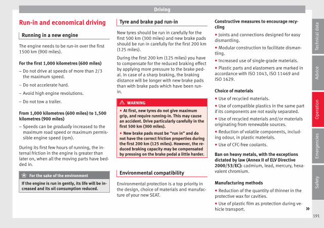
Driving
Run-in and economical driving
Running in a new engine
The engine needs to be run-in over the first1500 km (900 miles).
For the first 1,000 kilometres (600 miles)
– Do not drive at speeds of more than 2/3the maximum speed.
– Do not accelerate hard.
– Avoid high engine revolutions.
– Do not tow a trailer.
From 1,000 kilometres (600 miles) to 1,500kilometres (900 miles)
– Speeds can be gradually increased to themaximum road speed or maximum permis-sible engine speed (rpm).
During its first few hours of running, the in-ternal friction in the engine is greater thanlater on, when all the moving parts have bed-ded in.
For the sake of the environment
If the engine is run in gently, its life will be in-creased and its oil consumption reduced.
Tyre and brake pad run-in
New tyres should be run in carefully for thefirst 500 km (300 miles) and new brake padsshould be run in carefully for the first 200 km(125 miles).
During the first 200 km (125 miles) you haveto compensate for the reduced braking effectby applying more pressure to the brake ped-al. In case of a sharp braking, the brakingdistance will be longer with new brake padsthan with brake pads which have been run-in.
WARNING
● At first, new tyres do not give maximumgrip, and require running-in. This may causean accident. Drive particularly carefully in thefirst 500 km (300 miles).
● New brake pads must be “run in” and donot have the correct friction properties duringthe first 200 km (125 miles). However, the re-duced braking capacity may be compensatedby pressing on the brake pedal a little harder.
Environmental compatibility
Environmental protection is a top priority inthe design, choice of materials and manufac-ture of your new SEAT.
Constructive measures to encourage recy-cling
● Joints and connections designed for easydismantling.
● Modular construction to facilitate disman-tling.
● Increased use of single-grade materials.
● Plastic parts and elastomers are marked inaccordance with ISO 1043, ISO 11469 andISO 1629.
Choice of materials
● Use of recycled materials.
● Use of compatible plastics in the same partif its components are not easily separated.
● Use of recycled materials and/or materialsoriginating from renewable sources.
● Reduction of volatile components, includ-ing odour, in plastic materials.
● Use of CFC-free coolants.
Ban on heavy metals, with the exceptionsdictated by law (Annex II of ELV Directive2000/53/EC): cadmium, lead, mercury, hexa-valent chromium.
Manufacturing methods
● Reduction of the quantity of thinner in theprotective wax for cavities.
● Use of plastic film as protection during ve-hicle transport. »
191
Tech
nica
l dat
aA
dvic
eO
pera
tion
Emer
genc
ies
Saf
ety

Operation
● Use of solvent-free adhesives.
● Use of CFC-free coolants in cooling sys-tems.
● Recycling and energy recovery from resi-dues (RDF).
● Improvement in the quality of waste water.
● Use of systems for the recovery of residualheat (thermal recovery, enthalpy wheels,etc.).
● The use of water-soluble paints.
Economical and environmentally-friendly driving
Fuel consumption, environmental pollutionand wear to the engine, brakes and tyres de-pends in large part on your driving style. Byadopting an economical driving style and an-ticipating the traffic situation ahead, you caneasily reduce fuel consumption by 10-15%.Some tips on how to help you reduce pollu-tion while saving money are listed below.
Drive anticipating the traffic situation
A vehicle uses most fuel when accelerating.When you anticipate situations, you have tobrake less often and, thus, accelerate less. Ifit is possible, let the vehicle roll with a gearengaged, for example, if you see a red lightahead. The braking effect achieved in thisway helps to reduce the wear of brakes and
tyres; emissions and fuel consumption arereduced to zero (disconnection due to iner-tia).
Change gear early to save energy
An effective way of saving fuel is to changeup quickly through the gears. Running theengine at high rpm in the lower gears usesan unnecessary amount of fuel.
Manual gearbox: shift up from first to secondgear as soon as possible. We recommendthat, whenever possible, you change to ahigher gear upon reaching 2000 rpm. Followthe “recommended gear” indication that ap-pears on the instrument panel ››› page 190.
Avoid driving at high speed
We advise you not to drive at the top speedpermitted by the vehicle. Fuel consumption,exhaust emissions and noise levels all in-crease very rapidly at higher speeds. Drivingat moderate speeds will help to save fuel.
Avoid idling
It is worthwhile switching off the enginewhen waiting in a traffic jam, at level cross-ings or at traffic lights with a long red phase.The fuel saved after only 30 - 40 seconds isgreater than the amount of fuel needed to re-start the engine.
The engine takes a long time to warm upwhen it is idling. Mechanical wear and pollu-
tant emissions are also especially high dur-ing this initial warm-up phase. It is thereforebest to drive off immediately after startingthe engine. Avoid running the engine at highspeed.
Periodic maintenance
Periodic maintenance work guarantees that,before beginning a journey, you will not con-sume more than the required amount of fuel.A well-serviced engine gives you the benefitof improved fuel efficiency as well as maxi-mum reliability and an enhanced resale val-ue.
A badly serviced engine can consume up to10% more fuel than necessary.
Avoid short journeys
To reduce the consumption and emission ofpolluting exhaust gases, the engine and theexhaust gas filtration systems should reachthe optimum operating temperature.
With the engine cold, fuel consumption isproportionally higher. The engine does notwarm up and fuel consumption does not nor-malise until having driven approximately fourkilometres (2.5 miles). This is why we recom-mend avoiding short trips whenever possi-ble.
192
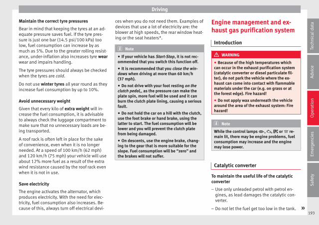
Driving
Maintain the correct tyre pressures
Bear in mind that keeping the tyres at an ad-equate pressure saves fuel. If the tyre pres-sure is just one bar (14.5 psi/100 kPa) toolow, fuel consumption can increase by asmuch as 5%. Due to the greater rolling resist-ance, under-inflation also increases tyre wearwear and impairs handling.
The tyre pressures should always be checkedwhen the tyres are cold.
Do not use winter tyres all year round as theyincrease fuel consumption by up to 10%.
Avoid unnecessary weight
Given that every kilo of extra weight will in-crease the fuel consumption, it is advisableto always check the luggage compartment tomake sure that no unnecessary loads are be-ing transported.
A roof rack is often left in place for the sakeof convenience, even when it is no longerneeded. At a speed of 100 km/h (62 mph)and 120 km/h (75 mph) your vehicle will useabout 12% more fuel as a result of the extrawind resistance caused by the roof rack evenwhen it is not in use.
Save electricity
The engine activates the alternator, whichproduces electricity. With the need for elec-tricity, fuel consumption also increases. Be-cause of this, always turn off electrical devi-
ces when you do not need them. Examples ofdevices that use a lot of electricity are: theblower at high speeds, the rear window heat-ing or the seat heaters*.
Note
● If your vehicle has Start-Stop, it is not rec-ommended that you switch this function off.
● It is recommended that you close the win-dows when driving at more than 60 km/h(37 mph).
● Do not drive with your foot resting on theclutch pedal,, as the pressure can make theplate spin, more fuel will be used and it canburn the clutch plate lining, causing a seriousfault.
● Do not hold the car on a hill with the clutch,use the foot brake or hand brake, using thelatter to start. The fuel consumption will belower and you will prevent the clutch platefrom being damaged.
● On descents, use the engine brake, chang-ing to the gear that is more suitable for theslope. Fuel consumption will be “zero” andthe brakes will not suffer.
Engine management and ex-haust gas purification system
Introduction
WARNING
● Because of the high temperatures whichcan occur in the exhaust purification system(catalytic converter or diesel particulate fil-ter), do not park the vehicle where the ex-haust can come into contact with flammablematerials under the car (e.g. on grass or atthe forest edge). Fire hazard!
● Do not apply wax underneath the vehiclearound the area of the exhaust system: Firehazard!
Note
While the control lamps , , or re-main lit, there may be engine problems, fuelconsumption may increase and the enginemay lose power.
Catalytic converter
To maintain the useful life of the catalyticconverter
– Use only unleaded petrol with petrol en-gines, as lead damages the catalytic con-verter.
– Do not let the fuel get too low in the tank. »193
Tech
nica
l dat
aA
dvic
eO
pera
tion
Emer
genc
ies
Saf
ety
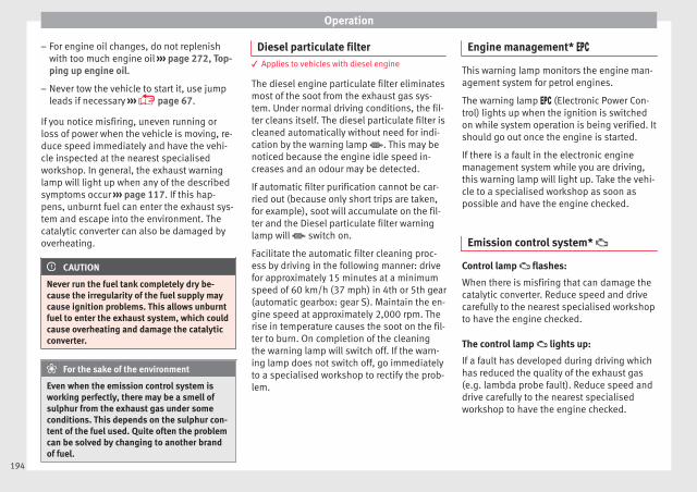
Operation
– For engine oil changes, do not replenishwith too much engine oil ››› page 272, Top-ping up engine oil.
– Never tow the vehicle to start it, use jumpleads if necessary ››› page 67.
If you notice misfiring, uneven running orloss of power when the vehicle is moving, re-duce speed immediately and have the vehi-cle inspected at the nearest specialisedworkshop. In general, the exhaust warninglamp will light up when any of the describedsymptoms occur ››› page 117. If this hap-pens, unburnt fuel can enter the exhaust sys-tem and escape into the environment. Thecatalytic converter can also be damaged byoverheating.
CAUTION
Never run the fuel tank completely dry be-cause the irregularity of the fuel supply maycause ignition problems. This allows unburntfuel to enter the exhaust system, which couldcause overheating and damage the catalyticconverter.
For the sake of the environment
Even when the emission control system isworking perfectly, there may be a smell ofsulphur from the exhaust gas under someconditions. This depends on the sulphur con-tent of the fuel used. Quite often the problemcan be solved by changing to another brandof fuel.
Diesel particulate filter3 Applies to vehicles with diesel engine
The diesel engine particulate filter eliminatesmost of the soot from the exhaust gas sys-tem. Under normal driving conditions, the fil-ter cleans itself. The diesel particulate filter iscleaned automatically without need for indi-cation by the warning lamp . This may benoticed because the engine idle speed in-creases and an odour may be detected.
If automatic filter purification cannot be car-ried out (because only short trips are taken,for example), soot will accumulate on the fil-ter and the Diesel particulate filter warninglamp will switch on.
Facilitate the automatic filter cleaning proc-ess by driving in the following manner: drivefor approximately 15 minutes at a minimumspeed of 60 km/h (37 mph) in 4th or 5th gear(automatic gearbox: gear S). Maintain the en-gine speed at approximately 2,000 rpm. Therise in temperature causes the soot on the fil-ter to burn. On completion of the cleaningthe warning lamp will switch off. If the warn-ing lamp does not switch off, go immediatelyto a specialised workshop to rectify the prob-lem.
Engine management*
This warning lamp monitors the engine man-agement system for petrol engines.
The warning lamp (Electronic Power Con-trol) lights up when the ignition is switchedon while system operation is being verified. Itshould go out once the engine is started.
If there is a fault in the electronic enginemanagement system while you are driving,this warning lamp will light up. Take the vehi-cle to a specialised workshop as soon aspossible and have the engine checked.
Emission control system*
Control lamp flashes:
When there is misfiring that can damage thecatalytic converter. Reduce speed and drivecarefully to the nearest specialised workshopto have the engine checked.
The control lamp lights up:
If a fault has developed during driving whichhas reduced the quality of the exhaust gas(e.g. lambda probe fault). Reduce speed anddrive carefully to the nearest specialisedworkshop to have the engine checked.
194

Driving
Engine pre-heating/fault system*
The warning lamp lights up to show that theglow plugs are preheating the diesel engine.
The control lamp lights up
If the control lamp lights up when the en-gine is started it means that the glow plugsare preheating. The engine can be startedstraight away when the lamp switches off.
Control lamp flashes
If a fault develops in the engine managementsystem while you are driving, the glow plugsystem lamp will flash . Take the vehicle toa specialised workshop as soon as possibleand have the engine checked.
Driving tips
Driving abroad
To drive abroad, the following must be takeninto consideration:
● For vehicles fitted with a catalytic converterensure that unleaded petrol is available forthe journey. See the chapter “Refuelling”. Au-tomobile organisations will have informationabout service station networks selling unlea-ded fuel.
● In some countries, it is possible that yourcar model is not sold, and therefore somespare parts are not available or the technicalservices may only be able to carry out limitedrepairs.
SEAT importers and distributors will gladlyprovide information about the technical prep-aration that your vehicle requires and alsoabout necessary maintenance and repairpossibilities.
Adhesive strips for headlights
In countries where vehicles drive on the otherside of the road to your home country, theasymmetric dipped beam may dazzle driversof oncoming vehicles.
To prevent dazzling, you must apply stickersto certain parts of the headlight lenses. Fur-ther information is available at any TechnicalService.
Driving on flooded roads
To prevent damage to the vehicle when driv-ing through water, for example, along a floo-ded road, please observe the following:
● The water should never come above thelower edge of the bodywork.
● Drive at pedestrian speed.
WARNING
After driving through water, mud, sludge,etc., the braking effect can be delayed slight-ly due to moisture build-up on the discs andbrake pads. Applying the brakes carefullyseveral times will remove the moisture andrestore the full braking effect.
CAUTION
● Driving through flooded areas may severelydamage vehicle components such as the en-gine, transmission, running gear or electricalsystem.
● Whenever driving through water, the Start-Stop system* must be switched off››› page 196.
Note
● Check the depth of the water before enter-ing the flooded zone.
● Do not stop in the water, drive in reverse, orstop the engine in any situation.
● Note that vehicles travelling in the oppositedirection may splash water that could exceedthe maximum permitted water height for yourvehicle.
● Avoid driving through salt water (corro-sion).
195
Tech
nica
l dat
aA
dvic
eO
pera
tion
Emer
genc
ies
Saf
ety

Operation
Driver assistance systems
Start-Stop System*
Related video
Fig. 181 Convenience
Description and operation
The Start-Stop system helps save fuel and re-duce CO2 emissions.
In Start-Stop mode, the engine will automati-cally switch off when the vehicle stops or isstopping; for example when stopping at traf-fic lights. The ignition remains switched onduring the stopping phase. The engine auto-matically switches back on when required. Inthis situation, the light of theSTART ENGINE STOP button stays on1).
As soon as the ignition is switched on, theStart-Stop function is automatically activa-ted.
Further information about the Start-Stop sys-tem can be found in the Easy Connect sys-tem: by pressing the button in the Vehi-cle status menu.
Basic requirements for the Start-Stop mode
● The driver door must be closed.
● The driver must have their seat belt fas-tened.
● The bonnet must be closed.
● The engine must have reached a minimumservice temperature.
● The reverse gear must not be engaged.
● The vehicle must not be on a very steepslope.
WARNING
● Never switch the engine off until the vehi-cle is stationary. The brake servo and powersteering functions will not be completely cov-ered under warranty. More force may also beneeded to turn the steering wheel or to brake.As you cannot steer and brake in the normalmanner, there is a greater risk of accidentsand serious injury.
● Never remove the key from the ignition ifthe vehicle is in motion. Otherwise, the steer-ing could lock making it impossible to steerthe vehicle.
● To avoid injury, make sure that the Start-Stop system is switched off when working inthe engine compartment ››› page 198.
CAUTION
The Start-Stop system must always beswitched off when driving through floodedareas ››› page 198.
Stopping/Starting the engine
Vehicles with a manual gearbox
– Before stopping the vehicle or when it isstopped, put it into neutral and release theclutch pedal. The engine will switch off. Thewarning lamp will appear on the instru-ment panel display. The engine may stopbefore the vehicle comes to a halt in thedeceleration phase (at 7 km/h).
– When the clutch pedal is pressed the en-gine will start up again. The warning lampwill switch off.
Vehicles with an automatic gearbox
– Use the foot brake to bring the vehicle to astop and keep the brake pedal presseddown with your foot. The engine will switchoff. The warning lamp will appear in the
1) Only in vehicles with Keyless Access.196
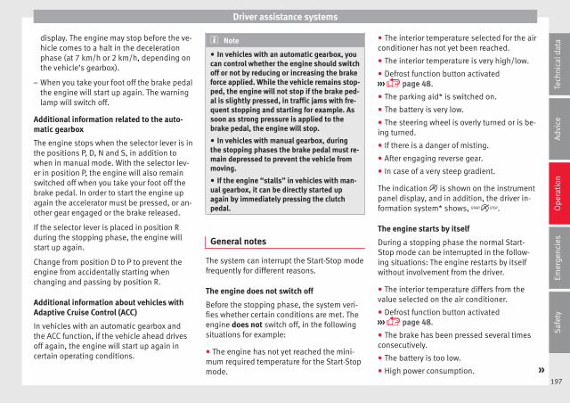
Driver assistance systems
display. The engine may stop before the ve-hicle comes to a halt in the decelerationphase (at 7 km/h or 2 km/h, depending onthe vehicle’s gearbox).
– When you take your foot off the brake pedalthe engine will start up again. The warninglamp will switch off.
Additional information related to the auto-matic gearbox
The engine stops when the selector lever is inthe positions P, D, N and S, in addition towhen in manual mode. With the selector lev-er in position P, the engine will also remainswitched off when you take your foot off thebrake pedal. In order to start the engine upagain the accelerator must be pressed, or an-other gear engaged or the brake released.
If the selector lever is placed in position Rduring the stopping phase, the engine willstart up again.
Change from position D to P to prevent theengine from accidentally starting whenchanging and passing by position R.
Additional information about vehicles withAdaptive Cruise Control (ACC)
In vehicles with an automatic gearbox andthe ACC function, if the vehicle ahead drivesoff again, the engine will start up again incertain operating conditions.
Note
● In vehicles with an automatic gearbox, youcan control whether the engine should switchoff or not by reducing or increasing the brakeforce applied. While the vehicle remains stop-ped, the engine will not stop if the brake ped-al is slightly pressed, in traffic jams with fre-quent stopping and starting for example. Assoon as strong pressure is applied to thebrake pedal, the engine will stop.
● In vehicles with manual gearbox, duringthe stopping phases the brake pedal must re-main depressed to prevent the vehicle frommoving.
● If the engine “stalls” in vehicles with man-ual gearbox, it can be directly started upagain by immediately pressing the clutchpedal.
General notes
The system can interrupt the Start-Stop modefrequently for different reasons.
The engine does not switch off
Before the stopping phase, the system veri-fies whether certain conditions are met. Theengine does not switch off, in the followingsituations for example:
● The engine has not yet reached the mini-mum required temperature for the Start-Stopmode.
● The interior temperature selected for the airconditioner has not yet been reached.
● The interior temperature is very high/low.
● Defrost function button activated››› page 48.
● The parking aid* is switched on.
● The battery is very low.
● The steering wheel is overly turned or is be-ing turned.
● If there is a danger of misting.
● After engaging reverse gear.
● In case of a very steep gradient.
The indication is shown on the instrumentpanel display, and in addition, the driver in-formation system* shows, .
The engine starts by itself
During a stopping phase the normal Start-Stop mode can be interrupted in the follow-ing situations: The engine restarts by itselfwithout involvement from the driver.
● The interior temperature differs from thevalue selected on the air conditioner.
● Defrost function button activated››› page 48.
● The brake has been pressed several timesconsecutively.
● The battery is too low.
● High power consumption. »197
Tech
nica
l dat
aA
dvic
eO
pera
tion
Emer
genc
ies
Saf
ety
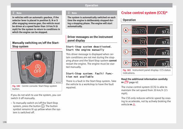
Operation
Note
In vehicles with an automatic gearbox, if theselector lever is placed in position D, N or Safter engaging reverse gear, the vehicle mustbe driven at a speed faster than 10 km/h (6mph) for the system to return to conditions inwhich the engine can be stopped.
Manually switching on/off the Start-Stop system
Fig. 182 Centre console: Start-Stop systembutton.
If you do not wish to use the system, you canswitch it off manually.
– To manually switch on/off the Start-Stopsystem, press the button . The buttonsymbol remains lit up yellow when the sys-tem is switched off.
Note
The system is automatically switched on eachtime the engine is deliberately stopped dur-ing a stopping phase. The engine will startautomatically.
Driver messages on the instrumentpanel display
Start-Stop system deactivated.Start the engine manuallyThis driver message is displayed when cer-tain conditions are not met during the stop-ping phase and the Start-Stop system cannotrestart the engine. The engine must be star-ted manually.
Start-Stop system: Fault! Func-tion not availableThere is a fault in the Start-Stop system. Takethe vehicle to a workshop to have the faultrepaired.
Cruise control system (CCS)*
Operation
Fig. 183 Instrument panel display: CCS statusindications.
Read the additional information carefully››› page 42
The cruise control system (CCS) is able tomaintain the set speed from 20 km/h (15mph).
The CSS only reduces vehicle speed by ceas-ing to accelerate, not by actively braking thevehicle ››› .
198

Driver assistance systems
Control lamp
Lights up
The Cruise Control System (GRA) is switched on and ac-tive.
OR: The Adaptive Cruise Control system (CCS) is switch-ed on and active.
OR: the speed limiter is switched on and active.
Several warning and control lamps light upfor a few seconds when the ignition is switch-ed on, signalling that the function is beingverified. They will switch off after a few sec-onds.
Displayed on the CCS screen
Status Fig. 183:
CCS temporarily switched off. The setspeed is displayed in small or darkenedfigures.
System error. Contact a specialised work-shop.
CCS switched on. The speed memory isempty.
The CCS is switched on. The set speed isdisplayed in large figures.
WARNING
Use of the cruise control could cause acci-dents and severe injuries if it is not possible
A
B
C
D
to drive at a constant speed maintaining thesafety distance.
● Do not use the cruise control in heavy traf-fic, if the distance from the vehicle in front isinsufficient, on steep roads, with severalbends or in slippery circumstances (snow,ice, rain or loose gravel), or on flooded roads.
● Never use the CCS when driving off-road oron unpaved roads.
● Always adapt your speed and the distanceto the vehicles ahead in line with visibility,weather conditions, the condition of the roadand the traffic situation.
● To avoid unexpected operation of the cruisecontrol system, turn it off every time you fin-ish using it.
● It is dangerous to use a set speed which istoo high for the prevailing road, traffic orweather conditions.
● When travelling down hills, the CCS cannotmaintain a constant speed. The vehicle tendsto accelerate under its own weight. Select alower gear or use the foot brake to slow thevehicle.
WARNING
Observe the safety warnings ››› in Warningsymbols on page 117.
Operating the cruise control system*
Read the additional information carefully››› page 42
The value indicated in the table in brackets(in mph, miles per hour) only refers to instru-ment panels with indications in miles.
Changing gear in CCS mode
The CCS decelerates as soon as the clutchpedal is pressed, intervening again automati-cally after a gear is engaged.
Travelling down hills with the CCS
When travelling down hills the CCS cannotmaintain a constant speed. Slow the vehicledown using the brake pedal and reducegears if required.
Automatic off
The cruise control system (CCS) is switchedoff automatically or temporarily:
● If the system detects a fault that could af-fect the working order of the CCS.
● If you press and maintain the acceleratorpedal for a certain time, driving faster thanthe stored speed.
● If the dynamic driving control systems in-tervene (e.g. ASR or ESC).
● If the brake pedal is pressed.
● If the airbag is triggered. »199
Tech
nica
l dat
aA
dvic
eO
pera
tion
Emer
genc
ies
Saf
ety
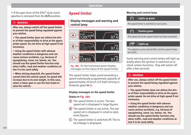
Operation
● If the gear lever of the DSG® dual clutchgearbox is removed from the D/S position.
WARNING
After use, always switch off the speed limiterto prevent the speed being regulated againstyour wishes.
● The speed limiter does not relieve the driv-er of their responsibility to drive at the appro-priate speed. Do not drive at high speed if notnecessary.
● Using the speed limiter with adverseweather conditions is dangerous and cancause serious accidents, e.g. because ofaquaplaning, snow, ice, leaves, etc. Youshould use the speed limiter function onlywhen traffic, road and weather conditions al-low it to be used safely.
● When driving downhill, the speed limitercannot limit the vehicle speed. Its speed willincrease due to its own weight. In this case,select a lower gear or use the foot brake toslow the vehicle.
Speed limiter
Display messages and warning andcontrol lamp
Fig. 184 On the instrument panel display:messages on the status of the speed limiter.
The speed limiter helps avoid exceeding aspeed individually programmed upwards ofapproximately 30 km/h (19 mph) driving inforwards gears ›››
Display messages on the speed limiter
Status ››› Fig. 184:
The speed limiter is active. The lastspeed set is displayed in large figures.
The speed limiter is not active. The lastspeed set is displayed in small or dark-ened figures.
The speed limiter is switched off. The to-tal mileage is displayed.
A
B
C
Warning and control lamp
Lights up green
The speed limiter is switched on and active.
Flashes green
The speed set by the speed limiter has been exceeded.
Lights up
The adaptive cruise control (ACC) and the speed limiterare active.
Some warning and control lamps will light upbriefly when the ignition is switched on tocheck certain functions. They will switch offafter a few seconds.
WARNING
After use, always switch off the speed limiterto prevent the speed being regulated againstyour wishes.
● The speed limiter does not relieve the driv-er of their responsibility to drive at the appro-priate speed. Do not drive at high speed if notnecessary.
● Using the speed limiter with adverseweather conditions is dangerous and cancause serious accidents, e.g. because ofaquaplaning, snow, ice, leaves, etc. Youshould use the speed limiter function onlywhen traffic, road and weather conditions al-low it to be used safely.
200

Driver assistance systems
● When driving downhill, the speed limitercannot limit the vehicle speed. Its speed willincrease due to its own weight. In this case,select a lower gear or use the foot brake toslow the vehicle.
WARNING
Observe the safety warnings ››› in Warningsymbols on page 117.
Note
● Different versions of the instrument panelare available and therefore the versions andinstructions on the display may vary.
● If when switching the ignition off, thecruise control system (CCS), the adaptivecruise control (ACC) or the speed limiter wereswitched on, then the cruise control system
or the adaptive cruise control will automati-cally switch themselves on when the ignitionis back on. However, no speed will be stored.The last set speed of the speed limiter will bestored.
Operate the speed limiter
Fig. 185 On the left of the steering column:control and buttons to operate the speed lim-iter.
Fig. 186 On the left of the steering column:third lever for operating the speed limiter.
FunctionPosition of the turn signal lever ››› Fig. 185or the third lever ››› Fig. 186
Effect
Switching on the speed limiterMove controller 1 to position and press button 2 of the turn signallever or move the third lever forward and press button 2 .
The system switches on. The last set speed of the speed lim-iter is stored. It does not take effect yet. »
201
Tech
nica
l dat
aA
dvic
eO
pera
tion
Emer
genc
ies
Saf
ety

Operation
FunctionPosition of the turn signal lever ››› Fig. 185or the third lever ››› Fig. 186
Effect
Switching between the speed limiter andcruise control (CCS) or the adaptive cruisecontrol (ACC) (with the speed limiterswitched on)
Press button 2 on the turn signal lever or button 2 on the third leverIt switches between the speed limiter and the CCS or theadaptive cruise control (ACC).
Activating the speed limiter Press button 3 on the turn signal lever or button 1 on the third lever.The current speed is stored as the maximum speed and thelimiter is switched on.
Temporarily switching off the speed limit-er limitation
Place control 1 of the turn signal lever in position or move the thirdlever into position .
The limiter is switched off temporarily. The speed will bestored.
Temporarily switch off the speed limiterlimitation pressing down the accelerator(kick-down)
Press down on the accelerator beyond the point of resistance (e.g. to over-take). Surpassing the set speed switches the speed limiter off temporarily.
The limiter is switched off temporarily. The speed will bestored. The limiter is reactivated automatically after return-ing to less than the set speed.
Switching the speed limiter on againPress button 3 on the turn signal lever or move the third lever into posi-tion .
The speed is limited to the set speed as soon as the speedyou are driving at is lower than the speed set as maximum.
Increasing the set speed of the limiter
Briefly press button 3 on the turn signal lever in the area or movethe third lever into position to increase the speed in small incre-ments of 1 km/h (1 mph) and set it.
The speed is limited to the set valuePress on the third lever to increase the speed in increments of10 km/h (5 mph) and set it.
Hold down button 3 on the turn signal lever in the area or holddown to increase continuously in increments of 10 km/h (5 mph)and set it.
Reducing the set speed of the limiter
Briefly press button 3 on the turn signal lever in the area or press 1 on the third lever to reduce the speed in small increments of 1 km/h(1 mph) and set it.
The speed is limited to the set valuePress on the third lever to reduce the speed in increments of10 km/h (5 mph) and set it.
Hold down button 3 on the turn signal lever in the area or holddown to reduce the speed continuously in increments of 10 km/h(5 mph) and set it.
202
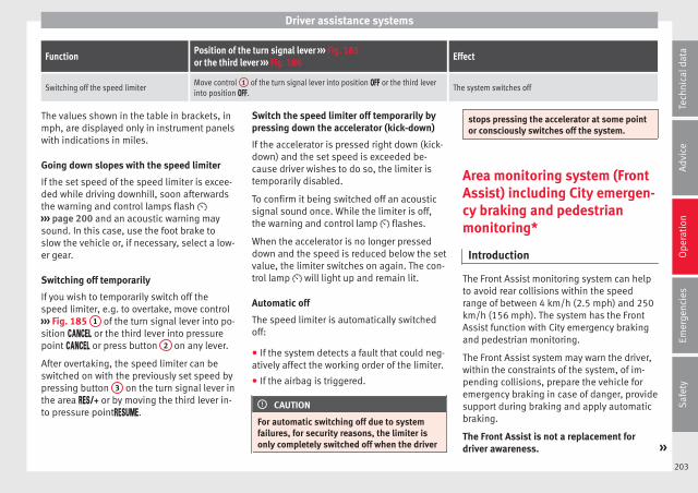
Driver assistance systems
FunctionPosition of the turn signal lever ››› Fig. 185or the third lever ››› Fig. 186
Effect
Switching off the speed limiterMove control 1 of the turn signal lever into position or the third leverinto position .
The system switches off
The values shown in the table in brackets, inmph, are displayed only in instrument panelswith indications in miles.
Going down slopes with the speed limiter
If the set speed of the speed limiter is excee-ded while driving downhill, soon afterwardsthe warning and control lamps flash ››› page 200 and an acoustic warning maysound. In this case, use the foot brake toslow the vehicle or, if necessary, select a low-er gear.
Switching off temporarily
If you wish to temporarily switch off thespeed limiter, e.g. to overtake, move control››› Fig. 185 1 of the turn signal lever into po-sition or the third lever into pressurepoint or press button 2 on any lever.
After overtaking, the speed limiter can beswitched on with the previously set speed bypressing button 3 on the turn signal lever inthe area or by moving the third lever in-to pressure point.
Switch the speed limiter off temporarily bypressing down the accelerator (kick-down)
If the accelerator is pressed right down (kick-down) and the set speed is exceeded be-cause driver wishes to do so, the limiter istemporarily disabled.
To confirm it being switched off an acousticsignal sound once. While the limiter is off,the warning and control lamp flashes.
When the accelerator is no longer presseddown and the speed is reduced below the setvalue, the limiter switches on again. The con-trol lamp will light up and remain lit.
Automatic off
The speed limiter is automatically switchedoff:
● If the system detects a fault that could neg-atively affect the working order of the limiter.
● If the airbag is triggered.
CAUTION
For automatic switching off due to systemfailures, for security reasons, the limiter isonly completely switched off when the driver
stops pressing the accelerator at some pointor consciously switches off the system.
Area monitoring system (FrontAssist) including City emergen-cy braking and pedestrianmonitoring*
Introduction
The Front Assist monitoring system can helpto avoid rear collisions within the speedrange of between 4 km/h (2.5 mph) and 250km/h (156 mph). The system has the FrontAssist function with City emergency brakingand pedestrian monitoring.
The Front Assist system may warn the driver,within the constraints of the system, of im-pending collisions, prepare the vehicle foremergency braking in case of danger, providesupport during braking and apply automaticbraking.
The Front Assist is not a replacement fordriver awareness. »
203
Tech
nica
l dat
aA
dvic
eO
pera
tion
Emer
genc
ies
Saf
ety

Operation
Distance warning
If the system detects that safety is endan-gered by the proximity of the vehicle in front,it may warn the driver by means of a messageon the instrument panel when driving at aspeed of between approximately 60 km/h(37 mph) and 250 km/h (156 mph)››› Fig. 187.
The warning moment varies depending onthe traffic situation and driver behaviour.
Advance warning
If the system detects a possible collision withthe vehicle in front, it may warn the driver bymeans of an audible warning and an indica-tion on the instrument panel when driving ata speed of between approximately 30 km/h(18 mph) and 250 km/h (156 mph)››› Fig. 187.
The warning moment varies depending onthe traffic situation and driver behaviour. Atthe same time, the vehicle will prepare for apossible emergency braking ››› .
Critical warning
If the driver fails to react to the advancewarning, the system may actively intervene inthe brakes when driving at a speed of be-tween approximately 30 km/h (18 mph) and250 km/h (156 mph), generating a brief joltto warn of the imminent collision.
Automatic braking
If the driver also fails to react to the advancewarning, the system may brake the vehicleautomatically, by progressively increasingbraking effect driving at a speed of betweenapproximately 4 km/h (2.5 mph) and250 km/h (156 mph). By reducing speed incase of a possible collision, the system maycontribute to reducing the consequences ofan accident.
Front assist
If the Front Assist notices that the driver isnot braking sufficiently in case of a collisionhazard, the system can increase braking ef-fect and thus avert the collision when drivingat a speed of between approximately 4 km/h(2.5 mph) and 250 km/h (156 mph). Frontassist only acts while the brake pedal ispressed down hard.
WARNING
The intelligent technology in the Front Assistcannot change the laws of physics. The driveris always responsible for braking in time. Ifthe Front Assist issues a warning, then, de-pending on the traffic circumstances, youmust brake immediately or dodge the obsta-cle.
● Adapt your speed and safe distance to thevehicle in front of you at all times to suit visi-bility, weather, road and traffic conditions.
● The Front Assist alone cannot avoid acci-dents and serious injuries.
● In complex driving situations, the Front As-sist may issue unnecessary warnings and in-tervene unnecessarily in braking, such as intraffic islands.
● If the operation of the Front Assist is im-paired, for example, by dirt or because the ra-dar sensor has lost its settings, the systemmay issue unnecessary warnings and inter-vene inopportunely in the braking.
● During driving, the Front Assist does not re-act to people or animals or vehicles crossingyour path or which approach you head-on inthe same lane.
● The driver must always be ready to takeover the control of the vehicle.
Note
● When the Front Assist causes a braking,the brake pedal is “harder”.
● Automatic interventions by the Front Assiston the brakes may be interrupted by pressingthe clutch, accelerator or moving the wheel.
● If the Front Assist does not work as descri-bed in this chapter (e.g. in intervenes severaltimes unnecessarily), switch it off. Have thesystem checked by a specialised workshop.SEAT recommends visiting a SEAT dealership.
204
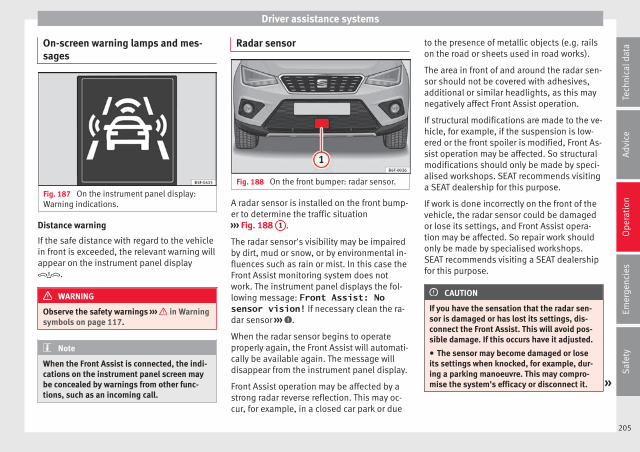
Driver assistance systems
On-screen warning lamps and mes-sages
Fig. 187 On the instrument panel display:Warning indications.
Distance warning
If the safe distance with regard to the vehiclein front is exceeded, the relevant warning willappear on the instrument panel display.
WARNING
Observe the safety warnings ››› in Warningsymbols on page 117.
Note
When the Front Assist is connected, the indi-cations on the instrument panel screen maybe concealed by warnings from other func-tions, such as an incoming call.
Radar sensor
Fig. 188 On the front bumper: radar sensor.
A radar sensor is installed on the front bump-er to determine the traffic situation››› Fig. 188 1 .
The radar sensor's visibility may be impairedby dirt, mud or snow, or by environmental in-fluences such as rain or mist. In this case theFront Assist monitoring system does notwork. The instrument panel displays the fol-lowing message: Front Assist: Nosensor vision! If necessary clean the ra-dar sensor ››› .
When the radar sensor begins to operateproperly again, the Front Assist will automati-cally be available again. The message willdisappear from the instrument panel display.
Front Assist operation may be affected by astrong radar reverse reflection. This may oc-cur, for example, in a closed car park or due
to the presence of metallic objects (e.g. railson the road or sheets used in road works).
The area in front of and around the radar sen-sor should not be covered with adhesives,additional or similar headlights, as this maynegatively affect Front Assist operation.
If structural modifications are made to the ve-hicle, for example, if the suspension is low-ered or the front spoiler is modified, Front As-sist operation may be affected. So structuralmodifications should only be made by speci-alised workshops. SEAT recommends visitinga SEAT dealership for this purpose.
If work is done incorrectly on the front of thevehicle, the radar sensor could be damagedor lose its settings, and Front Assist opera-tion may be affected. So repair work shouldonly be made by specialised workshops.SEAT recommends visiting a SEAT dealershipfor this purpose.
CAUTION
If you have the sensation that the radar sen-sor is damaged or has lost its settings, dis-connect the Front Assist. This will avoid pos-sible damage. If this occurs have it adjusted.
● The sensor may become damaged or loseits settings when knocked, for example, dur-ing a parking manoeuvre. This may compro-mise the system's efficacy or disconnect it. »
205
Tech
nica
l dat
aA
dvic
eO
pera
tion
Emer
genc
ies
Saf
ety
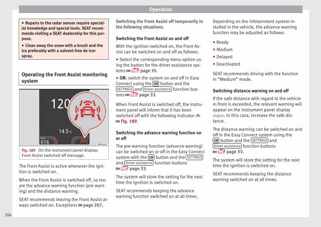
Operation
● Repairs to the radar sensor require special-ist knowledge and special tools. SEAT recom-mends visiting a SEAT dealership for this pur-pose.
● Clean away the snow with a brush and theice preferably with a solvent-free de-icerspray.
Operating the Front Assist monitoringsystem
Fig. 189 On the instrument panel display:Front Assist switched off message.
The Front Assist is active whenever the igni-tion is switched on.
When the Front Assist is switched off, so tooare the advance warning function (pre warn-ing) and the distance warning.
SEAT recommends leaving the Front Assist al-ways switched on. Exceptions ››› page 207,
Switching the Front Assist off temporarily inthe following situations.
Switching the Front Assist on and off
With the ignition switched on, the Front As-sist can be switched on and off as follows:
● Select the corresponding menu option us-ing the button for the driver assistance sys-tems ››› page 35.
● OR: switch the system on and off in EasyConnect using the button and theSETTINGS and Driver assistance function but-
tons ››› page 33.
When Front Assist is switched off, the instru-ment panel will inform that it has beenswitched off with the following indicator ››› Fig. 189.
Switching the advance warning function onor off
The pre-warning function (advance warning)can be switched on or off in the Easy Connectsystem with the button and the SETTINGS
and Driver assistance function buttons››› page 33.
The system will store the setting for the nexttime the ignition is switched on.
SEAT recommends keeping the advancewarning function switched on at all times.
Depending on the infotainment system in-stalled in the vehicle, the advance warningfunction may be adjusted as follows:
● Ready
● Medium
● Delayed
● Deactivated
SEAT recommends driving with the functionin “Medium” mode.
Switching distance warning on and off
If the safe distance with regard to the vehiclein front is exceeded, the relevant warning willappear on the instrument panel display. In this case, increase the safe dis-tance.
The distance warning can be switched on andoff in the Easy Connect system using the button and the SETTINGS andDriver assistance function buttons
››› page 33.
The system will store the setting for the nexttime the ignition is switched on.
SEAT recommends keeping the distancewarning switched on at all times.
206
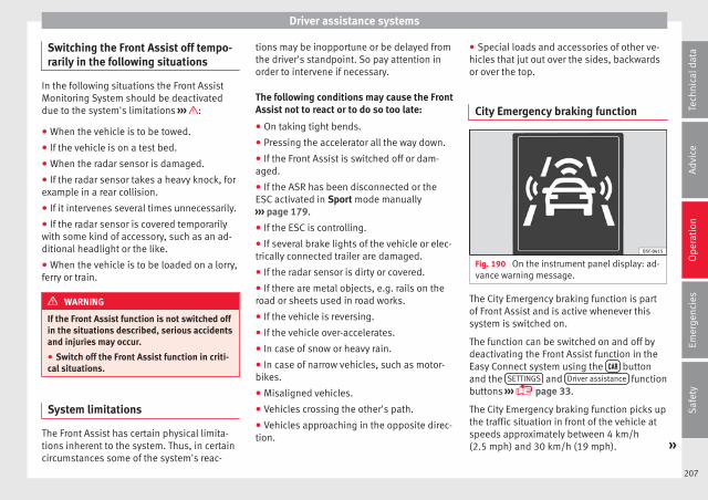
Driver assistance systems
Switching the Front Assist off tempo-rarily in the following situations
In the following situations the Front AssistMonitoring System should be deactivateddue to the system's limitations ››› :
● When the vehicle is to be towed.
● If the vehicle is on a test bed.
● When the radar sensor is damaged.
● If the radar sensor takes a heavy knock, forexample in a rear collision.
● If it intervenes several times unnecessarily.
● If the radar sensor is covered temporarilywith some kind of accessory, such as an ad-ditional headlight or the like.
● When the vehicle is to be loaded on a lorry,ferry or train.
WARNING
If the Front Assist function is not switched offin the situations described, serious accidentsand injuries may occur.
● Switch off the Front Assist function in criti-cal situations.
System limitations
The Front Assist has certain physical limita-tions inherent to the system. Thus, in certaincircumstances some of the system's reac-
tions may be inopportune or be delayed fromthe driver's standpoint. So pay attention inorder to intervene if necessary.
The following conditions may cause the FrontAssist not to react or to do so too late:
● On taking tight bends.
● Pressing the accelerator all the way down.
● If the Front Assist is switched off or dam-aged.
● If the ASR has been disconnected or theESC activated in Sport mode manually››› page 179.
● If the ESC is controlling.
● If several brake lights of the vehicle or elec-trically connected trailer are damaged.
● If the radar sensor is dirty or covered.
● If there are metal objects, e.g. rails on theroad or sheets used in road works.
● If the vehicle is reversing.
● If the vehicle over-accelerates.
● In case of snow or heavy rain.
● In case of narrow vehicles, such as motor-bikes.
● Misaligned vehicles.
● Vehicles crossing the other's path.
● Vehicles approaching in the opposite direc-tion.
● Special loads and accessories of other ve-hicles that jut out over the sides, backwardsor over the top.
City Emergency braking function
Fig. 190 On the instrument panel display: ad-vance warning message.
The City Emergency braking function is partof Front Assist and is active whenever thissystem is switched on.
The function can be switched on and off bydeactivating the Front Assist function in theEasy Connect system using the buttonand the SETTINGS and Driver assistance functionbuttons ››› page 33.
The City Emergency braking function picks upthe traffic situation in front of the vehicle atspeeds approximately between 4 km/h(2.5 mph) and 30 km/h (19 mph). »
207
Tech
nica
l dat
aA
dvic
eO
pera
tion
Emer
genc
ies
Saf
ety
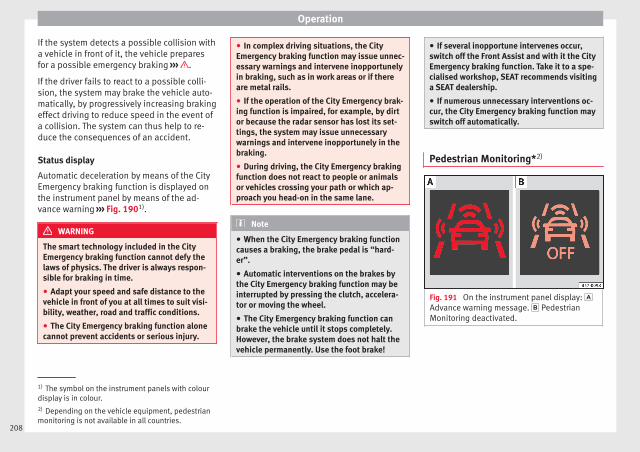
Operation
If the system detects a possible collision witha vehicle in front of it, the vehicle preparesfor a possible emergency braking ››› .
If the driver fails to react to a possible colli-sion, the system may brake the vehicle auto-matically, by progressively increasing brakingeffect driving to reduce speed in the event ofa collision. The system can thus help to re-duce the consequences of an accident.
Status display
Automatic deceleration by means of the CityEmergency braking function is displayed onthe instrument panel by means of the ad-vance warning ››› Fig. 1901).
WARNING
The smart technology included in the CityEmergency braking function cannot defy thelaws of physics. The driver is always respon-sible for braking in time.
● Adapt your speed and safe distance to thevehicle in front of you at all times to suit visi-bility, weather, road and traffic conditions.
● The City Emergency braking function alonecannot prevent accidents or serious injury.
● In complex driving situations, the CityEmergency braking function may issue unnec-essary warnings and intervene inopportunelyin braking, such as in work areas or if thereare metal rails.
● If the operation of the City Emergency brak-ing function is impaired, for example, by dirtor because the radar sensor has lost its set-tings, the system may issue unnecessarywarnings and intervene inopportunely in thebraking.
● During driving, the City Emergency brakingfunction does not react to people or animalsor vehicles crossing your path or which ap-proach you head-on in the same lane.
Note
● When the City Emergency braking functioncauses a braking, the brake pedal is “hard-er”.
● Automatic interventions on the brakes bythe City Emergency braking function may beinterrupted by pressing the clutch, accelera-tor or moving the wheel.
● The City Emergency braking function canbrake the vehicle until it stops completely.However, the brake system does not halt thevehicle permanently. Use the foot brake!
● If several inopportune intervenes occur,switch off the Front Assist and with it the CityEmergency braking function. Take it to a spe-cialised workshop, SEAT recommends visitinga SEAT dealership.
● If numerous unnecessary interventions oc-cur, the City Emergency braking function mayswitch off automatically.
Pedestrian Monitoring*2)
Fig. 191 On the instrument panel display: Advance warning message. PedestrianMonitoring deactivated.
1) The symbol on the instrument panels with colourdisplay is in colour.2) Depending on the vehicle equipment, pedestrianmonitoring is not available in all countries.
208
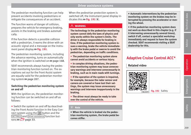
Driver assistance systems
The pedestrian monitoring function can helpprevent accidents involving pedestrians ormitigate the consequences of an accident.
The function warns of danger of collision,prepares the vehicle for emergency braking,assists in the braking and brakes automati-cally.
If the function detects a possible collisionwith a pedestrian, it warns the driver with anacoustic signal and a message on the instru-ment panel display ››› Fig. 191.
The pedestrian monitoring system, includingthe advance warning, turns on automaticallywhen the ignition is switched on ››› page 168.
SEAT recommends always having the pedes-trian monitoring function turned on. The ex-ceptions set out for the Front Assist systemare equally valid for the pedestrian monitor-ing system ››› page 207.
Switching the pedestrian monitoring systemon and off
With the ignition on, the pedestrian monitor-ing function can be switched on and off asfollows:
● Switch the system on and off by deactivat-ing the Front Assist function in the Easy Con-nect system using the button and theSETTINGS and Driver assistance function but-
tons ››› page 33.
When the pedestrian protection system isswitched off, the instrument panel display in-dicates this ››› Fig. 191 .
WARNING
The technology in the pedestrian monitoringsystem cannot defy the laws of physics andonly works within the system's limits. Thedriver is always responsible for braking intime. If the pedestrian monitoring system is-sues a warning, brake the vehicle immediate-ly with the brake pedal or swerve to avoid thepedestrian, depending on traffic conditions.
● The pedestrian monitoring system alonecannot avoid accidents or serious injury.
● In complex driving situations, the pedes-trian monitoring system may issue unneces-sary warnings and intervene unnecessarily inbraking, such as in main roads with turnings.
● If the operation of the system is impaired,for example, because the radar sensor andcamera are covered or have lost their set-tings, the system may issue unnecessarywarnings and intervene inopportunely in thebraking.
● The driver must always be ready to takeover the control of the vehicle.
Note
● When the vehicle is braked via the pedes-trian monitoring system, the brake pedal be-comes stiffer.
● Automatic interventions by the pedestrianmonitoring system on the brakes may be in-terrupted by pressing the accelerator or mov-ing the wheel.
● If the pedestrian monitoring system doesnot work as described in this chapter (e.g. ifit intervening unnecessarily several times),switch if off, contact a specialist workshopimmediately and request to have the systemchecked. SEAT recommends visiting a SEATdealership for this.
Adaptive Cruise Control ACC*
Related video
Fig. 192 Safety
209
Tech
nica
l dat
aA
dvic
eO
pera
tion
Emer
genc
ies
Saf
ety
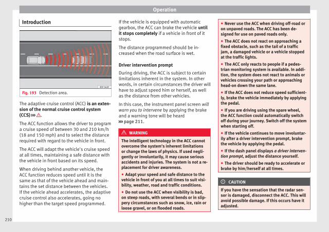
Operation
Introduction
Fig. 193 Detection area.
The adaptive cruise control (ACC) is an exten-sion of the normal cruise control system(CCS) ››› .
The ACC function allows the driver to programa cruise speed of between 30 and 210 km/h(18 and 150 mph) and to select the distancerequired with regard to the vehicle in front.
The ACC will adapt the vehicle's cruise speedat all times, maintaining a safe distance withthe vehicle in front based on its speed.
When driving behind another vehicle, theACC function reduces speed until it is thesame as that of the vehicle ahead and main-tains the set distance between the vehicles.If the vehicle ahead accelerates, the adaptivecruise control also accelerates, going nohigher than the target speed programmed.
If the vehicle is equipped with automaticgearbox, the ACC can brake the vehicle untilit stops completely if a vehicle in front of itstops.
The distance programmed should be in-creased when the road surface is wet.
Driver intervention prompt
During driving, the ACC is subject to certainlimitations inherent in the system. In otherwords, in certain circumstances the driver willhave to adjust speed him or herself, as wellas the distance from other vehicles.
In this case, the instrument panel screen willwarn you to intervene by applying the brakeand a warning tone will be heard››› page 211.
WARNING
The intelligent technology in the ACC cannotovercome the system's inherent limitationsor change the laws of physics. If used negli-gently or involuntarily, it may cause seriousaccidents and injuries. The system is not a re-placement for driver awareness.
● Adapt your speed and safe distance to thevehicle in front of you at all times to suit visi-bility, weather, road and traffic conditions.
● Do not use the ACC when visibility is bad,on steep roads, with several bends or in slip-pery circumstances such as snow, ice, rain orloose gravel, or on flooded roads.
● Never use the ACC when driving off-road oron unpaved roads. The ACC has been de-signed for use on paved roads only.
● The ACC does not react on approaching afixed obstacle, such as the tail of a trafficjam, a damaged vehicle or a vehicle stoppedat the traffic lights.
● The ACC only reacts to people if a pedes-trian monitoring system is available. In addi-tion, the system does not react to animals orvehicles crossing your path or approachinghead-on down the same lane.
● If the ACC does not reduce speed sufficient-ly, brake the vehicle immediately by applyingthe pedal.
● If you are driving using the spare wheel,the ACC function could automatically switchoff during your journey. Switch off the systemwhen starting off.
● If the vehicle continues to move involuntar-ily after a driver intervention prompt, brakethe vehicle by applying the pedal.
● If the dash panel displays a driver interven-tion prompt, adjust the distance yourself.
● The driver should be ready to accelerate orbrake by him/herself at all times.
CAUTION
If you have the sensation that the radar sen-sor is damaged, disconnect the ACC. This willavoid possible damage. If this occurs have itadjusted.
210

Driver assistance systems
● Repairs to the radar sensor require special-ist knowledge and special tools. SEAT recom-mends visiting a SEAT dealership for this pur-pose.
Note
● If the ACC system does not work as descri-bed in this chapter, do not use it until it hasbeen checked by a specialised workshop.SEAT recommends visiting a SEAT dealershipfor this purpose.
● Maximum speed with the ACC activated islimited to 210 km/h (150 mph).
● When the ACC is switched on, strangenoises may be heard during automatic brak-ing cause by the braking system.
Indications on the display, warningand control lamps
Fig. 194 On the instrument panel display: (A)ACC inactive (Standby). (B) ACC active.
Status display
Indications on the display ››› Fig. 194:
Vehicle ahead detected. ACC is not activeand is not regulating your speed.
Distance from the vehicle ahead. ACC isnot active and is not regulating your dis-tance.
1
2
Vehicle ahead detected. ACC is active andis regulating your speed.
Distance level 2 set by the driver.
ACC is active and is regulating your dis-tance based on speed.
Symbols on the instrument panel displayand control lamps.
››› in Warning symbols on page 117.
The speed reduction by the ACC tomaintain the distance from the vehi-cle in front is not sufficient.
Brake! apply the foot brake! Driver intervention prompt.
The ACC is not currently available.a)
With the vehicle stationary, switch off the engine andstart it up again. Check the radar sensor visually for dirt,ice or knocks. If it is still unavailable, refer to a special-ised workshop to have the system inspected.
a) The symbol on the instrument panels with colour display is incolour.
The ACC is active.
No vehicle is detected in front. The programmed speedremains constant. »
3
4
5
211
Tech
nica
l dat
aA
dvic
eO
pera
tion
Emer
genc
ies
Saf
ety

Operation
If the symbol is white: the ACC is ac-tive.
A vehicle in front has been detected. The ACC adjustsspeed and distance from the vehicle in front.
If the symbol is grey: ACC is inactive(Standby)
The system is switched on, but is not adjusting.
It lights up green:
The ACC is active.
Some warning and control lamps will light upbriefly when the ignition is switched on tocheck certain functions. They will switch offafter a few seconds.
WARNING
Observe the safety warnings ››› in Warningsymbols on page 117.
Note
When the ACC is connected, the indicationson the instrument panel screen may be con-cealed by warnings from other functions,such as an incoming call.
Radar sensor
Fig. 195 On the front bumper: radar sensor.
A radar sensor is installed on the front bump-er to determine the traffic situation››› Fig. 195 1 .
The radar sensor's visibility may be impairedby dirt, mud or snow, or by environmental in-fluences such as rain or mist. In this case theadaptive cruise control (ACC) does not work.The instrument panel displays the followingmessage: ACC: No sensor vision! Ifnecessary clean the radar sensor ››› .
When the radar sensor begins to operateproperly again, the ACC will automatically beavailable again. The message on the instru-ment panel screen will switch off and the ACCwill be reactivated again.
ACC operation may be affected by a strong ra-dar reverse reflection. This may occur, for ex-ample, in a closed car park or due to the
presence of metallic objects (e.g. rails on theroad or sheets used in road works).
The area in front of and around the radar sen-sor should not be covered with adhesives,additional or similar headlights, as this maynegatively affect ACC operation.
If structural modifications are made to the ve-hicle, for example, if the suspension is low-ered or the front spoiler is modified, ACC op-eration may be affected. So structural modifi-cations should only be made by specialisedworkshops. SEAT recommends visiting a SEATdealership for this purpose.
If work is done incorrectly on the front of thevehicle, the radar sensor could be damagedor lose its settings, and ACC operation maybe affected. So repair work should only bemade by specialised workshops. SEAT recom-mends visiting a SEAT dealership for this pur-pose.
CAUTION
If you have the sensation that the radar sen-sor is damaged or has lost its settings, dis-connect the ACC. This will avoid possibledamage. If this occurs have it adjusted.
● The sensor may become damaged or loseits settings when knocked, for example, dur-ing a parking manoeuvre. This may compro-mise the system's efficacy or disconnect it.
212
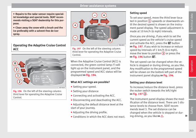
Driver assistance systems
● Repairs to the radar sensor require special-ist knowledge and special tools. SEAT recom-mends visiting a SEAT dealership for this pur-pose.
● Clean away the snow with a brush and theice preferably with a solvent-free de-icerspray.
Operating the Adaptive Cruise ControlACC
Fig. 196 On the left of the steering column:third lever for operating the Adaptive CruiseControl.
Fig. 197 On the left of the steering column:third lever for operating the Adaptive CruiseControl.
When the Adaptive Cruise Control (ACC) isconnected, the green control lamp willlight up on the instrument panel, and theprogrammed speed and ACC status will bedisplayed ››› Fig. 194.
What ACC settings are possible?
● Setting your speed.
● Setting your distance
● Connecting and activating the ACC.
● Disconnecting and deactivating the ACC.
● Adjusting the default distance level at thestart of your journey.
● Adjusting the driving profile.
● Conditions in which the ACC does not react.
Setting speed
To set your speed, move the third lever loca-ted in position 1 upwards or downwards un-til the desired speed is shown on the instru-ment panel display. The speed adjustment ismade at 10 km/h (6 mph) intervals.
Once you are driving, if you wish to set thecurrent speed as the vehicle’s cruise speedand activate the ACC, press the button››› Fig. 197. If you wish to increase or reducespeed by intervals of 1 km/h (0.6 mph),move the lever to position 2 or press the››› Fig. 196 button .
The set speed can be changed when the ve-hicle is stopped or during driving, as you like.Any modification to the programmed speedwill be shown on the bottom left part of theinstrument panel display ››› Fig. 194.
Setting your distance level
To increase/reduce the distance level, pressthe rocker switch towards the left/right››› Fig. 197 A .
The instrument panel display shows the mod-ification of the distance level. There are 5 dis-tance levels to choose from. SEAT recom-mends level 3. The set distance can bechanged when the vehicle is stopped or dur-ing driving, as you like ››› . »
213
Tech
nica
l dat
aA
dvic
eO
pera
tion
Emer
genc
ies
Saf
ety
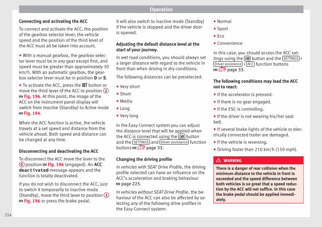
Operation
Connecting and activating the ACC
To connect and activate the ACC, the positionof the gearbox selector lever, the vehiclespeed and the position of the third level ofthe ACC must all be taken into account.
● With a manual gearbox, the gearbox selec-tor lever must be in any gear except first, andspeed must be greater than approximately 30km/h. With an automatic gearbox, the gear-box selector lever must be in position D or S.
● To activate the ACC, press the button ormove the third lever of the ACC to position 2
››› Fig. 196. At this point, the image of theACC on the instrument panel display willswitch from Inactive (Standby) to Active mode››› Fig. 194.
When the ACC function is active, the vehicletravels at a set speed and distance from thevehicle ahead. Both speed and distance canbe changed at any time.
Disconnecting and deactivating the ACC
To disconnect the ACC move the lever to the0 position ››› Fig. 196 (engaged). An ACCdeactivated message appears and thefunction is totally deactivated.
If you do not wish to disconnect the ACC, justto switch it temporarily to inactive mode(Standby), move the third lever to position 3
››› Fig. 196 or press the brake pedal.
It will also switch to inactive mode (Standby)if the vehicle is stopped and the driver dooris opened.
Adjusting the default distance level at thestart of your journey.
In wet road conditions, you should always seta larger distance with regard to the vehicle infront than when driving in dry conditions.
The following distances can be preselected:
● Very short
● Short
● Media
● Long
● Very long
In the Easy Connect system you can adjustthe distance level that will be applied whenthe ACC is connected using the buttonand the SETTINGS and Driver assistance functionbuttons ››› page 33.
Changing the driving profile
In vehicles with SEAT Drive Profile, the drivingprofile selected can have an influence on theACC’s acceleration and braking behaviour››› page 225.
In vehicles without SEAT Drive Profile, the be-haviour of the ACC can also be affected by se-lecting any of the following drive profiles inthe Easy Connect system:
● Normal
● Sport
● Eco
● Convenience
In this case, you should access the ACC set-tings using the button and the SETTINGS >Driver assistance > ACC function buttons
››› page 33.
The following conditions may lead the ACCnot to react:
● If the accelerator is pressed.
● If there is no gear engaged.
● If the ESC is controlling.
● If the driver is not wearing his/her seatbelt.
● If several brake lights of the vehicle or elec-trically connected trailer are damaged.
● If the vehicle is reversing.
● Driving faster than 210 km/h (150 mph).
WARNING
There is a danger of rear collision when theminimum distance to the vehicle in front isexceeded and the speed difference betweenboth vehicles is so great that a speed reduc-tion by the ACC will not suffice. In this casethe brake pedal should be applied immedi-ately.
214

Driver assistance systems
● The ACC may not be able to detect all situa-tions properly.
● “Stepping” on the accelerator may causethe ACC not to intervene in braking. Driverbraking will have priority over intervention bythe speed control or adaptive cruise control.
● Always be ready to use the brakes!
● Observe country-specific provisions gov-erning obligatory minimum distances be-tween vehicles.
● It is dangerous to activate control and re-sume the programmed speed if the road, traf-fic or weather conditions do not permit this.Risk of accident!
Note
● The programmed speed is erased once theignition or the ACC are switched off.
● When the traction control system (ASR) isdeactivated during acceleration or else theESC is activated in Sport* Mode(››› page 118), the ACC switches off automati-cally.
● In vehicles with the Start-Stop system, theengine switches off automatically during theACC stopping phase and restarts automatical-ly to begin driving.
Driver messages
ACC not available
The system can no longer continue to guar-antee safe vehicle detection and will be de-activated. The sensor has lost its setting or isdamaged. Take the vehicle to a specialisedworkshop and have the fault repaired.
ACC and Front Assist: currently not availa-ble. No sensor vision
This message will be displayed to the driver ifthe radar sensor's vision is impaired due, forexample, to leaves, snow, heavy fog or dirt.Clean the sensor.
ACC: currently not available. Gradient toosteep
The maximum road slope has been excee-ded, hence safe ACC operation cannot beguaranteed. The ACC cannot be switched on.
ACC: only available in D, S or M
Select the D/S or M position on the selectorlever.
ACC: parking brake applied
The ACC is deactivated if the parking brake isapplied. The ACC is available once again afterthe parking brake is released.
ACC: currently not available. Interventionof stability control
The message for the driver is displayed whenthe electronic stability control (ESC) inter-venes. In this case, the ACC is automaticallyswitched off.
ACC: Take action!
The message for the driver is displayed if,when the vehicle starts up on a hill with amild slope, the vehicle rolls back even al-though the ACC is activated. Apply the braketo stop the vehicle from moving/collidingwith another vehicle.
ACC: speed limit
The message for the driver is displayed if, invehicles with manual gearbox, the currentspeed is too low for the ACC mode.
The speed to be stored must be at least30 km/h (18 mph). The speed limiterswitches off if the speed falls below 20 km/h(12 mph).
ACC: available as of the 2nd gear
The ACC is operational as of the 2nd gear(manual gearbox).
ACC: engine speed
The message for the driver is displayed if,when the ACC accelerates or brakes, the driv-er does not shift up or down a gear in time, »
215
Tech
nica
l dat
aA
dvic
eO
pera
tion
Emer
genc
ies
Saf
ety
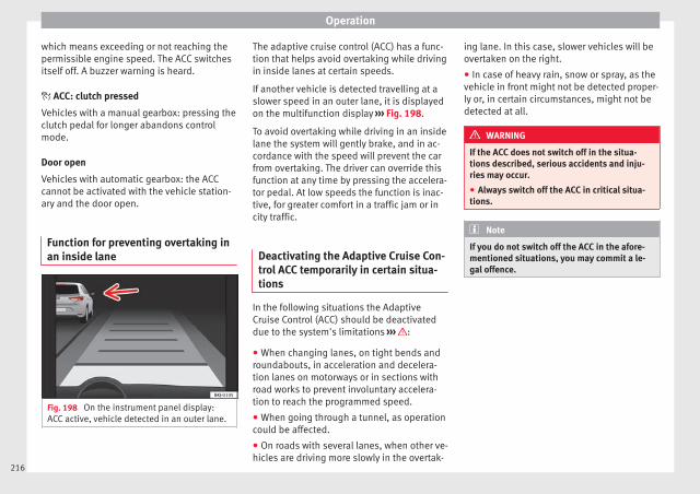
Operation
which means exceeding or not reaching thepermissible engine speed. The ACC switchesitself off. A buzzer warning is heard.
ACC: clutch pressed
Vehicles with a manual gearbox: pressing theclutch pedal for longer abandons controlmode.
Door open
Vehicles with automatic gearbox: the ACCcannot be activated with the vehicle station-ary and the door open.
Function for preventing overtaking inan inside lane
Fig. 198 On the instrument panel display:ACC active, vehicle detected in an outer lane.
The adaptive cruise control (ACC) has a func-tion that helps avoid overtaking while drivingin inside lanes at certain speeds.
If another vehicle is detected travelling at aslower speed in an outer lane, it is displayedon the multifunction display ››› Fig. 198.
To avoid overtaking while driving in an insidelane the system will gently brake, and in ac-cordance with the speed will prevent the carfrom overtaking. The driver can override thisfunction at any time by pressing the accelera-tor pedal. At low speeds the function is inac-tive, for greater comfort in a traffic jam or incity traffic.
Deactivating the Adaptive Cruise Con-trol ACC temporarily in certain situa-tions
In the following situations the AdaptiveCruise Control (ACC) should be deactivateddue to the system's limitations ››› :
● When changing lanes, on tight bends androundabouts, in acceleration and decelera-tion lanes on motorways or in sections withroad works to prevent involuntary accelera-tion to reach the programmed speed.
● When going through a tunnel, as operationcould be affected.
● On roads with several lanes, when other ve-hicles are driving more slowly in the overtak-
ing lane. In this case, slower vehicles will beovertaken on the right.
● In case of heavy rain, snow or spray, as thevehicle in front might not be detected proper-ly or, in certain circumstances, might not bedetected at all.
WARNING
If the ACC does not switch off in the situa-tions described, serious accidents and inju-ries may occur.
● Always switch off the ACC in critical situa-tions.
Note
If you do not switch off the ACC in the afore-mentioned situations, you may commit a le-gal offence.
216

Driver assistance systems
Special driving situations
Fig. 199 (A) Vehicle on a bend. (B) Motorcy-clist ahead out of range of the radar sensor.
Fig. 200 (C) Vehicle changing lanes. (D) Onevehicle turning and another stationary.
The adaptive cruise control (ACC) has certainphysical limitations inherent in the system.For example, certain reactions of the ACC, incertain circumstances, may be unexpected orcome late from the driver's point of view. Sopay attention in order to intervene if necessa-ry.
For example, the following traffic situationscall for the utmost attention:
Starting driving after a stopping phase (onlyvehicles with automatic gearbox)
After a stopping phase, the ACC may begindriving automatically when the vehicle infront drives off ››› .
When the ACC halts the vehicle (e.g. trafficjam), the instrument panel display shows theACC ready to start message. If the ve-hicle ahead drives off again, the ACC will alsodo so automatically.
If the vehicle ahead does not drive off again,the vehicle can be kept indefinitely in theACC ready to start status by operatingthe third lever repeatedly towards position
2 ››› Fig. 196 or by pressing the brake pedal.If the Press the brake message is shownon the instrument panel, press the brake. Ifyou do not, an acoustic warning will be heardand the ACC will switch to inactive mode(Standby). At this point, the vehicle may be-gin to move towards the stopped vehicleahead ››› .
Overtaking
When the turn signal lights up before the ve-hicle begins an overtaking manoeuvre, theACC accelerates the vehicle automaticallyand thus reduces the distance from the vehi-cle in front.
When the vehicle enters the overtaking lane,if the ACC does not detect another vehicle infront, it accelerates until it reaches the pro-grammed speed and maintains it.
System acceleration can be interrupted atany time by pressing the brake or moving thethird lever backwards ››› page 213. »
217
Tech
nica
l dat
aA
dvic
eO
pera
tion
Emer
genc
ies
Saf
ety
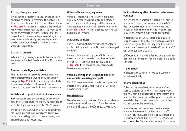
Operation
Driving through a bend
On entering or exiting bends, the radar sen-sor may no longer determine the vehicle infront or react to a vehicle in the adjacent lane››› Fig. 199 A. In these situations the vehiclemay brake unnecessarily or fail to react to re-act to the vehicle in front. In this case, thedriver has to intervene by accelerating or in-terrupting the braking process by applyingthe brake or pushing the third lever back-wards ››› page 213.
Driving in tunnels
When driving through tunnels the radar sen-sor may be limited. Switch off the ACC in tun-nels.
Narrow or misaligned vehicles
The radar sensor can only detect narrow ormisaligned vehicles when they are withinrange ››› Fig. 199 B. This applies particularlyto narrow vehicles such as motorbikes. Inthese cases, you should brake as necessary.
Vehicles with special loads and accessories
Special loads and accessories of other vehi-cles that jut out over the sides, backwards orover the top may be out of the ACC's range.
Switch off the ACC when driving behind vehi-cles with special loads and accessories orwhen overtaking them. In these cases, youshould brake as necessary.
Other vehicles changing lanes
Vehicles changing lanes a short distanceaway from your own can only be detectedwhen they are within range of the sensors.Consequently, the ACC will take longer to re-act ››› Fig. 200 C. In these cases, you shouldbrake as necessary.
Stationary vehicles
The ACC does not detect stationary objectswhile driving, such as traffic tails or damagedvehicles.
If a vehicle detected by the ACC turns ormoves over and there is a stationary vehiclein front of it, the ACC will not react to it››› Fig. 200 D. In these cases, you shouldbrake as necessary.
Vehicles driving in the opposite directionand vehicles crossing your path
The ACC does not react to vehicles approach-ing from the opposite direction or vehiclescrossing your path.
Metal objects
Metal objects, e.g. rails on the road or sheetsused in road works, can confuse the radarsensor and cause the ACC to react wrongly.
Factors that may affect how the radar sensoroperates
If laser sensor operation is impaired, due toheavy rain, spray, snow or mud, the ACC isdeactivated temporarily. The relevant textmessage will appear in the dash panel dis-play. If necessary, clean the radar sensor.
When the radar sensor begins to operateproperly again, the ACC will automatically beavailable again. The message on the instru-ment panel screen will switch off and the ACCwill be reactivated again.
ACC operation may be affected by a strong ra-dar reverse reflection, for example in a closedcar park.
Trailer mode
When driving with trailer the ACC controlsless dynamically.
Overheated brakes
If the brakes overheat, for example afterabrupt braking or in long and steep slopes,the ACC may be deactivated temporarily. Therelevant text message will appear in the dashpanel display. In this case, adaptive cruisecontrol cannot be activated.
Adaptive cruise control can be reactivatedonce brake temperature has cooled suffi-ciently. The message will disappear from theinstrument panel display. If the message ACCnot available remains on for quite a long
218
Driver assistance systems
time it means that there is a fault. Contact aspecialised workshop. SEAT recommends vis-iting a SEAT dealership.
WARNING
If you do not heed the Press the brakemessage, the vehicle may initiate an involun-tary movement and could crash into the vehi-cle ahead. In any event, before driving off,check that the road is clear. The radar sensormay not detect obstacles on the road. Thiscould cause an accident and serious injuries.If necessary, apply the brake.
219
Tech
nica
l dat
aA
dvic
eO
pera
tion
Emer
genc
ies
Saf
ety

Operation
Blind spot detector (BSD) withparking assistance (RCTA)*
Introduction
The blind spot detector (BSD) helps to detectthe traffic situation behind the vehicle.
The integrated parking assistant (RCTA) helpsthe driver when backing out of a parallelparking spot and in manoeuvring.
The blind spot detector has been developedfor driving on paved roads.
WARNING
The smart technology incorporated into theblind spot detector (BSD) with parking assis-tance (RCTA) included cannot overcome thelimits imposed by the laws of physics; it onlyworks within the limits of the system. Acci-dents and severe injury may occur if the blindspot detection system or the rear cross trafficalert are used negligently or involuntarily.The system is not a replacement for driverawareness.
● Adapt your speed and safe distance to thevehicle in front of you at all times to suit visi-bility, weather, road and traffic conditions.
● Keep your hands on the wheel at all timesto be ready to intervene in the steering at anytime.
● Pay attention to the control lamps that maycome on in the external rear view mirrors and
on the instrument panel, and follow any in-structions they may give.
● The blind spot assistant could react to anyspecial constructions that might be presenton the sides of the vehicle: e.g. high or irreg-ular dividers. This may cause erroneous warn-ings.
● Never use the blind spot detector with rearcross traffic alert on unpaved roads. The blindspot detector with rear cross traffic alert hasbeen designed for use on paved roads.
● Always pay attention to the vehicle's sur-roundings.
● Never use the blind spot detector or theparking assistant if the radar sensors aredirty.
● The external rear view mirror control lampsmay have limited functionality due to solarradiation.
CAUTION
● The radar sensors on the rear bumper maybe damaged or shifted in the event of a colli-sion, for example, when entering or exiting aparking space. This may result in the systemdisconnecting itself, or at least possibly hav-ing its functionality diminished.
● In order to ensure that the radar sensorswork properly, keep the rear bumper free ofsnow and ice and do not cover it.
● The rear bumper should only be paintedwith paint authorised by SEAT. The blind spot
detector's functions may be limited or workincorrectly if other paints are used.
Note
If the blind spot detector with parking assis-tant does not work as described in this chap-ter, do not use it and contact a specialisedworkshop.
Control lamps
Control lamp in external rear view mirrors:
Lights up
Lights up once briefly: the blind spot detector is activa-ted and ready to operate.
Lights up: blind spot detector has detected a vehicle inthe blind spot.
Flashes
The blind spot detector has detected a vehicle in theblind spot and the turn signal has been turned on in thedirection of the detected vehicle ››› .
Some warning and control lamps will light upbriefly when the ignition is switched on tocheck certain functions. They will switch offafter a few seconds.
If there are no indications from the controllamp in the external rear view mirror, this
220
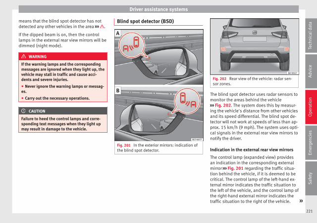
Driver assistance systems
means that the blind spot detector has notdetected any other vehicles in the area ››› .
If the dipped beam is on, then the controllamps in the external rear view mirrors will bedimmed (night mode).
WARNING
If the warning lamps and the correspondingmessages are ignored when they light up, thevehicle may stall in traffic and cause acci-dents and severe injuries.
● Never ignore the warning lamps or messag-es.
● Carry out the necessary operations.
CAUTION
Failure to heed the control lamps and corre-sponding text messages when they light upmay result in damage to the vehicle.
Blind spot detector (BSD)
Fig. 201 In the exterior mirrors: indication ofthe blind spot detector.
Fig. 202 Rear view of the vehicle: radar sen-sor zones.
The blind spot detector uses radar sensors tomonitor the areas behind the vehicle››› Fig. 202. The system does this by measur-ing the vehicle's distance from other vehiclesand its speed differential. The blind spot de-tector will not work at speeds of less than ap-prox. 15 km/h (9 mph). The system uses opti-cal signals in the external rear view mirrors tonotify the driver.
Indication in the external rear view mirrors
The control lamp (expanded view) providesan indication in the corresponding externalmirror ››› Fig. 201 regarding the traffic situa-tion behind the vehicle, if it is deemed to becritical. The control lamp of the left-hand ex-ternal mirror indicates the traffic situation tothe left of the vehicle, and the control lamp ofthe right-hand external mirror indicates thetraffic situation to the right of the vehicle. »
221
Tech
nica
l dat
aA
dvic
eO
pera
tion
Emer
genc
ies
Saf
ety
Operation
In the case of retrofitted tinted windows orwindows with tinted film, the indications ofthe external mirrors may not be seen clearlyor correctly.
Keep the external mirrors clean and free ofsnow and ice, and do not cover them with ad-hesives or other similar materials.
Radar sensors
The radar sensors are located on the left andright of the bumper and are not visible from
the outside ››› Fig. 202. The sensors monitorboth the blind spot and traffic behind the ve-hicle ››› Fig. 203, ››› Fig. 204. The range to thesides of the vehicle is a bit larger than thewidth of a lane.
The lane width is not detected individually,but is rather pre-configured in the system.Thus if you are driving in wide lanes or in be-tween two lanes, the indications may be in-correct. Furthermore, the system can detectvehicles driving in the lane next to you (if
there are any), and can also detect stationaryobjects such as dividers, and thus give an in-correct indication.
222
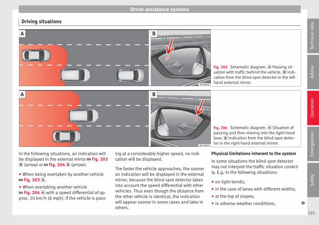
Driver assistance systems
Driving situations
Fig. 203 Schematic diagram: Passing sit-uation with traffic behind the vehicle. Indi-cation from the blind spot detector in the left-hand external mirror.
Fig. 204 Schematic diagram: Situation ofpassing and then moving into the right-handlane. Indication from the blind spot detec-tor in the right-hand external mirror.
In the following situations, an indication willbe displayed in the external mirror ››› Fig. 203 (arrow) or ››› Fig. 204 (arrow):
● When being overtaken by another vehicle››› Fig. 203 .
● When overtaking another vehicle››› Fig. 204 with a speed differential of ap-prox. 10 km/h (6 mph). If the vehicle is pass-
ing at a considerably higher speed, no indi-cation will be displayed.
The faster the vehicle approaches, the sooneran indication will be displayed in the externalmirror, because the blind spot detector takesinto account the speed differential with othervehicles. Thus even though the distance fromthe other vehicle is identical, the indicationwill appear sooner in some cases and later inothers.
Physical limitations inherent to the system
In some situations the blind spot detectormay not interpret the traffic situation correct-ly. E.g. in the following situations:
● on tight bends;
● in the case of lanes with different widths;
● at the top of slopes;
● in adverse weather conditions; »
223
Tech
nica
l dat
aA
dvic
eO
pera
tion
Emer
genc
ies
Saf
ety

Operation
● in the case of special constructions to theside of the vehicle, e.g., high or irregular di-viders.
Parking assistant (RCTA)
Fig. 205 Schematic representation of the rearcross traffic alert: zone monitored around thevehicle exiting the parking space.
The parking assistant uses the radar sensorson the rear bumper ››› Fig. 202 to monitor thetraffic crossing behind the vehicle as it backsout of a parallel parking space or as it is be-ing manoeuvred, for example in very low visi-bility conditions.
If the system detects that someone else onthe road is approaching the rear of the vehi-cle ››› Fig. 205, an acoustic alarm is heard.
In addition to the acoustic alarm, if the vehi-cle is equipped with the park assist system,the driver is also informed by means of a vis-ual signal on the radio screen. This signal isdisplayed in the form of a red strip at theback of the image of the vehicle on the radioscreen. This strip displays the side of the ve-hicle towards which traffic is approaching.
Automatic braking to reduce damages
If the rear cross traffic alert detects thatsomeone else on the road is approaching therear of the vehicle and the driver does notstep on the brake, the system will engage thebrakes automatically.
The parking system helps the driver by auto-matically engaging the brakes to reduce anydamage. The system will brake automaticallyif the vehicle is reversing at a speed of ap-proximately 1-12 km (1-7 mph). Once it hasdetected that the vehicle has stopped, thesystem will keep the vehicle stopped for ap-prox. 2 seconds.
After automatically braking to reduce dam-age, the system will not be able to automati-cally brake again for approximately 10 sec-onds.
You can interrupt the automatic braking bystepping hard on the accelerator pedal or thebrake pedal in order to regain control of thevehicle.
WARNING
The smart technology incorporated into therear cross traffic alert cannot overcome thelimits imposed by the laws of physics; it onlyworks within the limits of the system. Theparking assistant function should not temptyou into taking any risks. The system is not areplacement for driver awareness.
● The system should never be used in limitedvisibility conditions or complicated traffic,e.g., in high-traffic areas or when crossingmultiple lanes.
● Be sure to always be aware of the vehicle'ssurroundings, since the system often fails todetect things such as bicycles or pedestrians.
● The rear cross traffic alert itself will notbrake the vehicle to a complete stop.
Using the blind spot detector (BSD)with parking assistant (RCTA)
Activating and deactivating the blind spotdetector (BSD) with parking assistant (RCTA)
The blind spot detector with parking assis-tant can be switched on and off by accessingthe Assistance systems menu on thedash panel display using the steering wheelcontrols. If the vehicle is equipped with amultifunction camera, it can also be ac-cessed by means of the driver assistance sys-tems key located on the main beam head-light lever.
224

Driver assistance systems
Open the Assistants menu.
● Blind spot
● Exit Assist
If the verification box on the control panel ischecked , the functionality will be automat-ically activated at ignition.
When the blind spot detector is ready to op-erate, the indications in the external mirrorswill turn on briefly as confirmation.
When the vehicle is restarted, the last adjust-ment in the system will remain active.
If the blind spot detector was automaticallydeactivated, it will only be possible to restartthe system after turning the vehicle off andrestarting it.
Automatic deactivation of the blind spot de-tector (BSD)
The radar sensors of the blind spot detectorwith rear cross traffic alert will be automati-cally deactivated when, among other rea-sons, one of the sensors is detected to bepermanently covered. This may be the case if,for example, there is a layer of snow or ice infront of one of the sensors.
The relevant text message will appear in thedash panel display.
Trailer mode
The Blind spot detector and the rear crosstraffic alert will be automatically deactivatedand it will be impossible to activate them ifthe tow hitch is electrically connected to atrailer or other similar object.
As soon as the driver starts to drive with atrailer connected electrically to the vehicle, amessage will appear on the instrument paneldisplay indicating that the blind spot detec-tor and the rear cross traffic alert are deacti-vated. Once the trailer has been unhitchedfrom the vehicle, if you want to use the blindspot detector and the rear cross traffic alert,you will have to reactivate them in the corre-sponding menu.
If the towing hitch is not factory equipped,then the blind spot detector and the rearcross traffic alert will have to be deactivatedmanually when driving with a trailer.
SEAT Drive Profile*
Introduction
SEAT Drive Profile enables the driver tochoose between four profiles or modes, Nor-mal, Sport, Eco and Individual, thatmodify the behaviour of various vehicle func-tions, providing different driving experiences.
The Individual profile can be configuredaccording to personal preferences. The otherprofiles are fixed.
Description
Depending on the equipment fitted in the ve-hicle, SEAT Drive Profile can operate on thefollowing functions:
Engine
Depending on the profile selected, the en-gine responds more spontaneously or morein harmony with the movements of the accel-erator. Additionally, when Eco mode is selec-ted, the Start-stop function is automaticallyactivated.
In vehicles with automatic transmission, thegear change points are modified to positionthem in lower or higher engine speed ranges.Additionally, the Eco mode activates the In-ertia function, enabling consumption to befurther reduced.
In manual gearbox vehicles, Eco mode cau-ses the gear change recommendation indica-tions that appear on the instrument panel tovary, facilitating more efficient driving.
“Dual Ride” suspension
The “Dual Ride” suspension features a com-fortable suspension in the Eco and Normal »
225
Tech
nica
l dat
aA
dvic
eO
pera
tion
Emer
genc
ies
Saf
ety

Operation
profiles, suitable for daily use. Contrastingwith this it features a sporty suspension inthe Sport profile, suitable for a sporty driv-ing style. In the Individual profile the sus-pension can be switched between Normal orSport, depending on personal preference.
In the event of a fault in the “Dual Ride” sus-pension, the following message is displayedon the instrument panel screen Fault:damping setting.
Address
Power steering becomes more robust inSport mode to enable a sportier drivingstyle.
Air conditioning
In vehicles with Climatronic, this can operatein eco mode, especially restricting fuel con-sumption.
Adaptive Cruise Control (ACC)
According to the active driving profile, the ac-celeration gradient of the adaptive cruisecontrol varies.
Setting driving mode
Fig. 206 Next to the gearbox lever: MODE but-ton.
You can select from Normal, Sport, Ecoand Individual.
You can select the required mode either byrepeatedly pressing the button MODE››› Fig. 206, or on the touch screen, in themenu that opens when the above button ispressed.
An icon on the Easy Connect system displayinforms about the active mode.
The MODE button light remains lit up yellowwhen the active mode is different to Normal.
Driving pro-file
Characteristics
Normal Offers a balanced driving experience,suitable for everyday use.
Driving pro-file
Characteristics
SportProvides a complete dynamic perform-ance in the vehicle, enabling the user amore sporty driving style.
EcoPlaces the vehicle in a particularly lowstate of consumption, facilitating afuel-saving driving style that is respect-ful to the environment.
Individual
Enables some configurations to bemodified by pressing the Profilesettings button. The functions thatcan be adjusted depend on the equip-ment fitted in the vehicle.
WARNING
When operating SEAT Drive Profile, pay atten-tion to all traffic: doing otherwise could causean accident.
Note
● When the vehicle is switched off it will al-ways store the driving profile that was selec-ted when the ignition key was removed. Nev-ertheless, when the engine is restarted, theengine and the gear will not restart in the set-ting selected. For engine and gear to revert tothe desired position, select the correspond-ing drive profile again or press the Easy Con-nect system button repeatedly.
226
Driver assistance systems
● Your speed and driving style must alwaysbe adjusted to visibility, weather, and trafficconditions.
● The eco mode is not available when towinga trailer.
Kick-down
The kick-down feature allows maximum ac-celeration to be reached.
If the eco* ››› page 226 mode has been se-lected in SEAT Drive Profile*, and the acceler-ator is pressed beyond a hard point, the en-gine power is automatically controlled to giveyour vehicle maximum acceleration.
WARNING
Please note that if the road surface is slip-pery or wet, the kick-down feature couldcause the driving wheels to spin, which couldresult in skidding.
Fatigue detection (break rec-ommendation)*
Related video
Fig. 207 Safety
Introduction
The Fatigue detection informs the driverwhen their driving behaviour shows signs offatigue.
WARNING
Do not let the comfort afforded by the Fatiguedetection system tempt you into taking anyrisks when driving. Take regular breaks, suffi-cient in length when making long journeys.
● The driver always assumes the responsibil-ity of driving to their full capacity.
● Never drive if you are tired.
● The system does not detect the tiredness ofthe driver in all circumstances. Consult the in-formation in the section ››› page 228, Systemlimitations.
● In some situations, the system may incor-rectly interpret an intended driving manoeu-vre as driver tiredness.
● No warning is given in the event of the ef-fect called microsleep!
● Please observe the indications on the in-strument panel and act as is necessary.
Note
● Fatigue detection has been developed fordriving on motorways and well paved roadsonly.
● If there is a fault in the system, have itchecked by a specialised workshop.
Function and operation
Fig. 208 On the instrument panel display: fa-tigue detection symbol.
Fatigue detection determines the driving be-haviour of the driver when starting a journey, »
227
Tech
nica
l dat
aA
dvic
eO
pera
tion
Emer
genc
ies
Saf
ety
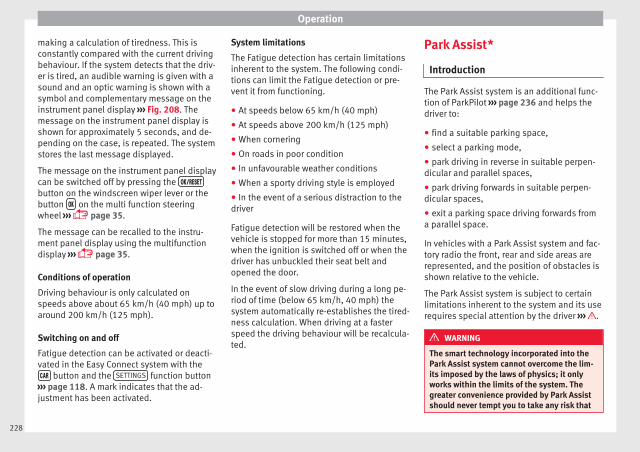
Operation
making a calculation of tiredness. This isconstantly compared with the current drivingbehaviour. If the system detects that the driv-er is tired, an audible warning is given with asound and an optic warning is shown with asymbol and complementary message on theinstrument panel display ››› Fig. 208. Themessage on the instrument panel display isshown for approximately 5 seconds, and de-pending on the case, is repeated. The systemstores the last message displayed.
The message on the instrument panel displaycan be switched off by pressing the button on the windscreen wiper lever or thebutton on the multi function steeringwheel ››› page 35.
The message can be recalled to the instru-ment panel display using the multifunctiondisplay ››› page 35.
Conditions of operation
Driving behaviour is only calculated onspeeds above about 65 km/h (40 mph) up toaround 200 km/h (125 mph).
Switching on and off
Fatigue detection can be activated or deacti-vated in the Easy Connect system with the button and the SETTINGS function button
››› page 118. A mark indicates that the ad-justment has been activated.
System limitations
The Fatigue detection has certain limitationsinherent to the system. The following condi-tions can limit the Fatigue detection or pre-vent it from functioning.
● At speeds below 65 km/h (40 mph)
● At speeds above 200 km/h (125 mph)
● When cornering
● On roads in poor condition
● In unfavourable weather conditions
● When a sporty driving style is employed
● In the event of a serious distraction to thedriver
Fatigue detection will be restored when thevehicle is stopped for more than 15 minutes,when the ignition is switched off or when thedriver has unbuckled their seat belt andopened the door.
In the event of slow driving during a long pe-riod of time (below 65 km/h, 40 mph) thesystem automatically re-establishes the tired-ness calculation. When driving at a fasterspeed the driving behaviour will be recalcula-ted.
Park Assist*
Introduction
The Park Assist system is an additional func-tion of ParkPilot ››› page 236 and helps thedriver to:
● find a suitable parking space,
● select a parking mode,
● park driving in reverse in suitable perpen-dicular and parallel spaces,
● park driving forwards in suitable perpen-dicular spaces,
● exit a parking space driving forwards froma parallel space.
In vehicles with a Park Assist system and fac-tory radio the front, rear and side areas arerepresented, and the position of obstacles isshown relative to the vehicle.
The Park Assist system is subject to certainlimitations inherent to the system and its userequires special attention by the driver ››› .
WARNING
The smart technology incorporated into thePark Assist system cannot overcome the lim-its imposed by the laws of physics; it onlyworks within the limits of the system. Thegreater convenience provided by Park Assistshould never tempt you to take any risk that
228

Driver assistance systems
may compromise safety. The system is not areplacement for driver awareness.
● Any accidental movement of the vehiclecould result in serious injury.
● Adapt your speed and driving style at alltimes to suit visibility, weather, road and traf-fic conditions.
● Certain surfaces of objects and garmentsdo not reflect the ultrasound sensors' sig-nals. The system cannot detect, at least cor-rectly, these objects or people wearing suchclothes.
● Ultrasound sensor signals may be affectedby external sound sources. In certain circum-stances this may prevent them from detect-ing people or objects.
● The ultrasound sensors have blind spots inwhich obstacles and people are not regis-tered.
● Monitor the area around the vehicle at alltimes, since the ultrasound sensors do notdetect small children, animals or certain ob-jects in all situations.
WARNING
Quick turns of the steering wheel when park-ing or exiting a parking space with Park As-sist can cause serious injury.
● Do not hold the steering wheel during ma-noeuvres to park or exit a parking space untilthe system requests it. Doing so disables thesystem during the manoeuvre, resulting inthe parking being cancelled.
CAUTION
● In certain circumstances, the ultrasonicsensors do not detect objects such as trailertongues, bars, fences, posts or thin trees, oran open (or opening) rear lid, which coulddamage the vehicle.
● Retrofitting of certain accessories to the ve-hicle, such as a bicycle rack, may interferewith the operation of the Park Assist systemand cause damage.
● The Park Assist system uses as a referenceparked vehicles, curbs and other objects.Make sure that the tyres and wheels are notdamaged while parking. If necessary, oppor-tunely interrupt the parking manoeuvre toavoid damaging the vehicle.
● The ultrasound sensors on the bumper maybe damaged or shifted in the event of a colli-sion, for example, when entering or exiting aparking space.
● If you use high-pressure or vapour equip-ment to clean the ultrasound sensors, do notapply it directly unless very briefly and al-ways from a distance of more than 10 cm.
● A registration plate or plate holder on thefront with larger than the space for the regis-tration plate, or a registration plate that iscurved or warped can cause:
– false detections,
– loss of sensor visibility.
– cancellation of the parking manoeuvre ordefective parking.
● If one of the ultrasonic sensors is damaged,the area corresponding to that group of sen-sors (front or rear) is deactivated and cannotbe activated until the fault is corrected. How-ever, you can still use the sensors of the oth-er bumper as per usual. If there is a fault inthe system, consult a specialist workshop.SEAT recommends visiting a SEAT dealershipfor this.
Note
● In order to guarantee good system opera-tion, keep the ultrasound sensors of thebumper clean, free of snow or ice, and do notcover them with adhesives or other objects.
● Certain sources of noise, such as rough as-phalt or paving stones and the noise of othervehicles can induce the Park Assist system orParkPilot to give erroneous warnings.
● In order to become familiar with the systemand its functions, SEAT recommends that youpractice operating the Park Assist system inan area where there is not too much traffic orin a car park.
229
Tech
nica
l dat
aA
dvic
eO
pera
tion
Emer
genc
ies
Saf
ety
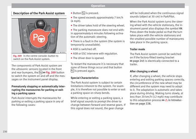
Operation
Description of the Park Assist system
Fig. 209 In the centre console: button toswitch on the Park Assist system.
The components of Park Assist system arethe ultrasonic sensors located in the frontand rear bumpers, the ››› Fig. 209 buttonto switch the system on and off and the mes-sages on the instrument panel display.
Prematurely stopping or automatically inter-rupting the manoeuvres for parking or exit-ing a parking space
Park Assist interrupts the manoeuvres forparking or exiting a parking space in any ofthe following cases:
● Button is pressed.
● The speed exceeds approximately 7 km/h(4 mph).
● The driver takes hold of the steering wheel.
● The parking manoeuvre does not end with-in approximately 6 minutes following activa-tion of the automatic steering.
● There is a fault in the system (the system istemporarily unavailable).
● ASR is switched off.
● ASR or ESC intervene with regulation.
● The driver door is opened.
To restart the manoeuvre it is necessary thatnone of these things occur and that button is pressed again.
Special Characteristics
The Park Assist system is subject to certainlimitations inherent to the system. For exam-ple, it is therefore not possible to enter or exita parking space on sharp bends.
While entering or exiting a parking space, abrief signal sounds to prompt the driver tochange between forward and reverse gears. Ifthis signal does not sound, the gear change
will be indicated when the continuous signalsounds (object at 30 cm) in ParkPilot.
When the Park Assist system turns the steer-ing wheel with the vehicle stationary, the in-strument panel also displays the symbol .Press down the brake pedal so that the turntakes place with the vehicle stationary andthe smallest possible number of manoeuvrestake place in the parking space.
Trailer mode
The Park Assist system cannot be switchedon if the factory-fitted towing bracket››› page 245 is electrically connected to atrailer.
After changing a wheel
If, after changing a wheel, the vehicle stopsentering and exiting parking spaces correctly,the circumference of the new wheel may bedifferent and the system may need to adaptto it. The adaptation is automatic and takesplace during driving. Making turns slowly, atless than 20 km/h (12 mph) may contributeto this adaptation process ››› in Introduc-tion on page 228.
230

Driver assistance systems
Selecting a parking mode
Fig. 210 Overview of reduced displays for park-ing modes: Parallel parking in reverse. Per-pendicular parking in reverse. Perpendicularparking forwards.
Fig. 211 On the instrument panel display:displaying the Park Assist system with re-duced display.
Selecting a parking mode with Park Assistwith prior step in front of the space
After activating the Park Assist system andafter detecting a parking space, the displayon the instrument panel proposes a parkingmode. The Park Assist system selects theparking mode automatically. The selected
mode is shown on the instrument panel dis-play ››› Fig. 211. The reduced display of otherpossible parking modes is also shown››› Fig. 210. If the mode selected by the sys-tem does not correspond to the desiredmode, you can select another mode by press-ing button ››› Fig. 209.
Action
1.The necessary conditions to park with Park Assisthave to be met ››› page 233.
2.
Press button .
A control lamp on the button lights up whenthe system is switched on. Additionally, the se-lected parking mode is shown on the instrumentpanel display and the reduced display shows an-other parking mode it can be changed to.
Action
3.
Turn on the corresponding turn signal towardsthe side of the road where you are parking. Theinstrument panel displays the side correspond-ing to the road. By default, if the turn signal isnot on, it parks on the right in the direction oftraffic.
4.
If necessary, press the button again tochange parking mode.
Once you have switched to all possible parkingmodes, if the button is pressed again, thesystem switches off.
5.Press the button again to switch the systemback on.
6.Follow the instructions displayed on the instru-ment panel while paying attention to traffic anddrive the vehicle past the parking space. »
231
Tech
nica
l dat
aA
dvic
eO
pera
tion
Emer
genc
ies
Saf
ety

Operation
Special case of perpendicular parking spaceto park forwards without driving past first
Action
1.The necessary conditions to park with Park Assisthave to be met ››› page 233.
2.Drive forward towards the parking space whilepaying attention to traffic and stop the vehicle.
Action
3.
Press the button once.
A control lamp on the button lights up whenthe system is switched on. Additionally, the se-lected parking mode is shown on the instrumentpanel display without reduced display.
4.Release the steering wheel ››› in Introductionon page 229.
232

Driver assistance systems
Park with Park Assist
Fig. 212 On the instrument panel display: paral-lel parking. Finding a parking space. Park-ing position. Manoeuvring.
Fig. 213 On the instrument panel display: per-pendicular parking. Finding a parking space. Parking position. Manoeuvring.
Key to Fig. 212 and Fig. 213:
Message to move forwards
Your vehicle
Parked vehicle
Parking space detected
Message to park
Message to press the brake pedal
Progress bar
1
2
3
4
5
6
7
Progress bars
The progress bar››› Fig. 212 7 and ››› Fig. 213 7 on thescreen of the instrument panel displays therelative distance to be covered. The greaterthe distance, the fuller the progress bar.When driving forward, the content of the pro-gress bar decreases upwards, and when re-versing, it decreases downwards.
Necessary conditions to park with Park As-sist
For parallel parkingspaces
For perpendicularparking spaces
The traction control system (ASR) must be turned on››› page 179. »
233
Tech
nica
l dat
aA
dvic
eO
pera
tion
Emer
genc
ies
Saf
ety
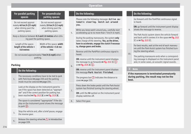
Operation
For parallel parkingspaces
For perpendicularparking spaces
Do not exceed approxi-mately 40 km/h (25 mph)
when driving past theparking space.
Do not exceed approxi-mately 20 km/h (12 mph)
when driving past theparking space.
Keep a distance between 0.5 and 2.0 metres when driv-ing past the parking space.
Length of the space:length of the vehicle +
0.8 metres
Width of the space: widthof the vehicle + 0.8 me-
tres
Do not exceed approximately 7 km/h (4 mph) whenparking.
Parking
Do the following:
1.The necessary conditions have to be met to parkwith Park Assist ››› page 233 and the parkingmode must be selected ››› page 231.
2.
Look at the display on the instrument panel tosee if the space has been detected as “appropri-ate” and if the correct position for parking hasbeen reached ››› Fig. 212 or ››› Fig. 213 .
The space is considered “appropriate” if the dis-play on the instrument panel shows the messageto park 5 .
3.Stop the vehicle and, after a brief pause, engagethe reverse gear.
4.Release the steering wheel ››› in Introductionon page 229.
Do the following:
5.
Please note the following message: Active au-tomatic steering. Watch out aroundyou.While you keep watch around you, carefully startaccelerating up to no more than 7 km/h (4 mph).
During the parking manoeuvre, the system onlytakes charge of the steering. You, as the driver,have to accelerate, engage the clutch if necessa-ry, change gears and brake.
6.
Reverse until the ParkPilot continuous signal isheard.
OR: reverse until the instrument panel displaysthe message to go forwards ››› Fig. 212 1
or ››› Fig. 213 1 .
OR: reverse until the instrument panel displaysthe message Park Assist finished.
The progress bar 7 indicates the distance tocover ››› page 233.
7.
Press down the brake pedal until the Park Assistsystem has finished turning the steering wheel.
OR: until the symbol on the instrument paneldisplay switches off.
8. Select first gear.
Do the following:
9.
Go forward until the ParkPilot continuous signalis heard.
OR: go forward until the instrument panel displayshows the message to reverse.
The Park Assist system steers the vehicle forwardand back until it centres it in the space ››› Fig. 212 or ››› Fig. 213 .
10.
For best results, wait at the end of each manoeu-vre until the Park Assist system has finished turn-ing the steering wheel.
The parking manoeuvre ends when a correspond-ing message is displayed on the instrument paneland, in some cases, an acoustic signal sounds.
Note
If the manoeuvre is terminated prematurelyduring parking, the result may not be thebest.
234
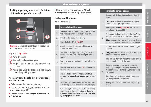
Driver assistance systems
Exiting a parking space with Park As-sist (only for parallel spaces)
Fig. 214 On the instrument panel display: ex-iting a parallel parking space.
Key to the Fig. 214:
Parked vehicle
Your vehicle in reverse gear
Progress bar to indicate the distance leftto cover
Message giving the proposed manoeuvreto exit the parking space
Necessary conditions to exit a parking spacewith Park Assist
● Only for parallel parking spaces
● The traction control system (ASR) must beturned on ››› page 179.
● Length of the space: length of the vehicle+ 0.5 metres
1
2
3
4
● Do not exceed approximately 7 km/h(4 mph) when exiting the parking space.
Exiting a parking space
Do the following:
For parallel parking spaces
1.The necessary conditions to exit a parking spacewith Park Assist have to be met ››› page 235.
2. Switch on the engine ››› page 168.
3.
Press the button ››› Fig. 209.
A control lamp on the button lights up whenthe system is switched on.
4.Turn on the corresponding turn signal towardsthe road you will enter when exiting the parkingspace.
5.Engage reverse gear or turn the selector lever toposition R.
6.
Release the steering wheel ››› in Introductionon page 229.
Please note the following message: Activeautomatic steering. Watch out aroundyou.While you keep watch around you, carefully startaccelerating up to no more than 7 km/h (4 mph).
When exiting the parking space, the system onlytakes charge of the steering. You, as the driver,have to accelerate, engage the clutch if necessa-ry, change gears and brake.
For parallel parking spaces
7.
Reverse until the ParkPilot continuous signal isheard.
OR: reverse until the instrument panel displayshows the message to go forward.
The progress bar ››› Fig. 214 3 indicates the dis-tance to cover ››› page 233.
8.
Press down the brake pedal until the Park Assistsystem has finished turning the steering wheel.
OR: press down the brake pedal until the sym-bol on the instrument panel display switches off.
9.
Go forward until the ParkPilot continuous signalis heard.
OR: go forward until the instrument panel displayshows the message to reverse.
The Park Assist system steers the vehicle forwardand back until it can exit the space.
10.
The vehicle can exit the space when a corre-sponding message is displayed on the instru-ment panel and, in some cases, an acoustic sig-nal sounds.
Take charge of the steering with the turning an-gle set by the Park Assist system.
11.Paying attention to the traffic, exit the parkingspace.
235
Tech
nica
l dat
aA
dvic
eO
pera
tion
Emer
genc
ies
Saf
ety
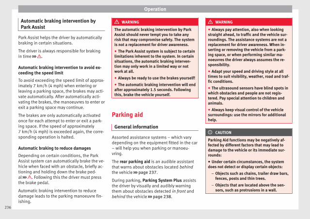
Operation
Automatic braking intervention byPark Assist
Park Assist helps the driver by automaticallybraking in certain situations.
The driver is always responsible for brakingin time ››› .
Automatic braking intervention to avoid ex-ceeding the speed limit
To avoid exceeding the speed limit of approx-imately 7 km/h (4 mph) when entering orleaving a parking space, the brakes may acti-vate automatically. After automatically acti-vating the brakes, the manoeuvres to enter orexit a parking space may continue.
The brakes are only automatically activatedonce for each attempt to enter or exit a park-ing space. If the speed of approximately7 km/h (4 mph) is exceeded again, the corre-sponding operation is halted.
Automatic braking to reduce damages
Depending on certain conditions, the ParkAssist system can automatically brake the ve-hicle when faced with an obstacle, briefly ac-tioning and holding down the brake ped-al ››› . Following this the driver must pressthe brake pedal.
Automatic braking intervention to reducedamage leads to the parking manoeuvre fin-ishing.
WARNING
The automatic braking intervention by ParkAssist should never tempt you to take anyrisk that may compromise safety. The systemis not a replacement for driver awareness.
● The Park Assist system is subject to certainlimitations inherent to the system. In certainsituations, the automatic braking interven-tion may only work in a limited way or notwork at all.
● Always be ready to use the brakes yourself!
● The automatic braking intervention will endafter approximately 1.5 seconds. Followingthis, brake the vehicle yourself.
Parking aid
General information
Assorted assistance systems – which varydepending on the equipment fitted in the car– will help you when parking or manoeu-vring.
The rear parking aid is an audible assistantthat warns about obstacles located behindthe vehicle ››› page 237.
During parking, Parking System Plus assiststhe driver by visually and audibly warningthem about obstacles detected in front andbehind the vehicle ››› page 238.
WARNING
● Always pay attention, also when lookingstraight ahead, to traffic and the vehicle sur-roundings. The assistance systems are not areplacement for driver awareness. When in-serting or removing the vehicle from a park-ing space, or when performing similar ma-noeuvres the driver always assumes the re-sponsibility.
● Adapt your speed and driving style at alltimes to suit visibility, weather, road and traf-fic conditions.
● The ultrasound sensors have blind spots inwhich obstacles and people are not regis-tered. Pay special attention to children andanimals.
● Always keep visual control of the vehiclesurroundings: use the mirrors for additionalhelp.
CAUTION
Parking Aid functions may be negatively af-fected by different factors that may lead todamage to the vehicle or its immediate sur-rounds:
● Under certain circumstances, the systemdoes not detect or display certain objects:
– Objects such as chains, trailer draw bars,fences, posts and thin trees.
– Objects that are located above the sen-sors, such as protrusions in a wall.
236
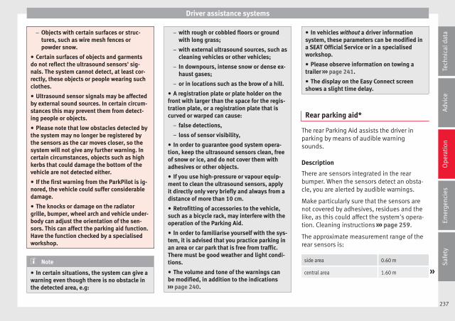
Driver assistance systems
– Objects with certain surfaces or struc-tures, such as wire mesh fences orpowder snow.
● Certain surfaces of objects and garmentsdo not reflect the ultrasound sensors' sig-nals. The system cannot detect, at least cor-rectly, these objects or people wearing suchclothes.
● Ultrasound sensor signals may be affectedby external sound sources. In certain circum-stances this may prevent them from detect-ing people or objects.
● Please note that low obstacles detected bythe system may no longer be registered bythe sensors as the car moves closer, so thesystem will not give any further warning. Incertain circumstances, objects such as highkerbs that could damage the bottom of thevehicle are not detected either.
● If the first warning from the ParkPilot is ig-nored, the vehicle could suffer considerabledamage.
● The knocks or damage on the radiatorgrille, bumper, wheel arch and vehicle under-body can adjust the orientation of the sen-sors. This can affect the parking aid function.Have the function checked by a specialisedworkshop.
Note
● In certain situations, the system can give awarning even though there is no obstacle inthe detected area, e.g:
– with rough or cobbled floors or groundwith long grass;
– with external ultrasound sources, such ascleaning vehicles or other vehicles;
– In downpours, intense snow or dense ex-haust gases;
– or in locations such as the brow of a hill.
● A registration plate or plate holder on thefront with larger than the space for the regis-tration plate, or a registration plate that iscurved or warped can cause:
– false detections,
– loss of sensor visibility,
● In order to guarantee good system opera-tion, keep the ultrasound sensors clean, freeof snow or ice, and do not cover them withadhesives or other objects.
● If you use high-pressure or vapour equip-ment to clean the ultrasound sensors, applyit directly only very briefly and always from adistance of more than 10 cm.
● Retrofitting of accessories to the vehicle,such as a bicycle rack, may interfere with theoperation of the Parking Aid.
● In order to familiarise yourself with the sys-tem, it is advised that you practice parking inan area or car park that is free from traffic.There must be good weather and light condi-tions.
● The volume and tone of the warnings canbe modified, in addition to the indications››› page 240.
● In vehicles without a driver informationsystem, these parameters can be modified ina SEAT Official Service or in a specialisedworkshop.
● Please observe information on towing atrailer ››› page 241.
● The display on the Easy Connect screenshows a slight time delay.
Rear parking aid*
The rear Parking Aid assists the driver inparking by means of audible warningsounds.
Description
There are sensors integrated in the rearbumper. When the sensors detect an obsta-cle, you are alerted by audible warnings.
Make particularly sure that the sensors arenot covered by adhesives, residues and thelike, as this could affect the system's opera-tion. Cleaning instructions ››› page 259.
The approximate measurement range of therear sensors is:
side area 0.60 m
central area 1.60 m »
237
Tech
nica
l dat
aA
dvic
eO
pera
tion
Emer
genc
ies
Saf
ety

Operation
As you approach the obstacle, the time inter-val between the audible warnings will be re-duced. When you reach around 0.30 m thewarning will be constant: Do not continue tomove forward (or backward) ››› in Generalinformation on page 236, ››› in General in-formation on page 236 !
If you maintain separation from the obstacle,the volume of the warning begins to reduceafter four seconds (does not affect the toneof the constant warning).
Activating/Deactivating
When engaging reverse gear, the parking aidis automatically switched on. This is con-firmed with a short warning.
On disengaging reverse gear, the Parking Aidsystem is disconnected immediately.
Parking system plus*
Fig. 215 Represented area.
Parking system plus assists you audibly andvisually when parking.
There are sensors integrated in the front andrear bumpers. When they detect an obstacle,you are alerted by audible warnings and visu-ally on the Easy Connect system.
In the event of danger of a frontal collision,the audible warnings come from the front ofthe vehicle, and in the event of the danger ofa rear-end collision they come from the rear.
Make particularly sure that the sensors arenot covered by adhesives, residues and thelike, as this could affect the system's opera-tion. Cleaning instructions ››› page 259.
The approximate measurement range of thesensors is:
1.20 mA
0.60 m
1.60 m
0.60 m
As you approach the obstacle, the time inter-val between the audible warnings will be re-duced. When you reach around 0.30 m thewarning will be constant: do not continue tomove forward (or backward)!
If you maintain separation from the obstacle,the volume of the warning begins to reduceafter four seconds (does not affect the toneof the constant warning).
Parking Aid operation
Fig. 216 Centre console: parking aid button.
Manual connection of Parking Aid
● Press the button once. The symbol onthe button will light up yellow.
B
C
D
238
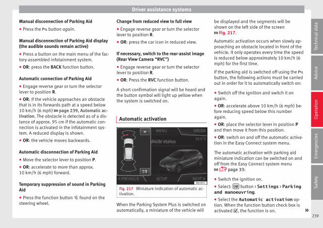
Driver assistance systems
Manual disconnection of Parking Aid
● Press the button again.
Manual disconnection of Parking Aid display(the audible sounds remain active)
● Press a button on the main menu of the fac-tory-assembled infotainment system.
● OR: press the BACK function button.
Automatic connection of Parking Aid
● Engage reverse gear or turn the selectorlever to position R.
● OR: If the vehicle approaches an obstaclethat is in its forwards path at a speed below10 km/h (6 mph) ››› page 239, Automatic ac-tivation. The obstacle is detected as of a dis-tance of approx. 95 cm if the automatic con-nection is activated in the infotainment sys-tem. A reduced display is shown.
● OR: the vehicle moves backwards.
Automatic disconnection of Parking Aid
● Move the selector lever to position P.
● OR: accelerate to more than approx.10 km/h (6 mph) forward.
Temporary suppression of sound in ParkingAid
● Press the function button found on thesteering wheel.
Change from reduced view to full view
● Engage reverse gear or turn the selectorlever to position R.
● OR: press the car icon in reduced view.
If necessary, switch to the rear-assist image(Rear View Camera “RVC”)
● Engage reverse gear or turn the selectorlever to position R.
● OR: Press the RVC function button.
A short confirmation signal will be heard andthe button symbol will light up yellow whenthe system is switched on.
Automatic activation
Fig. 217 Miniature indication of automatic ac-tivation.
When the Parking System Plus is switched onautomatically, a miniature of the vehicle will
be displayed and the segments will beshown on the left side of the screen››› Fig. 217.
Automatic activation occurs when slowly ap-proaching an obstacle located in front of thevehicle. It only operates every time the speedis reduced below approximately 10 km/h (6mph) for the first time.
If the parking aid is switched off using the button, the following actions must be carriedout in order for it to automatically switch on:
● Switch off the ignition and switch it onagain.
● OR: accelerate above 10 km/h (6 mph) be-fore reducing speed below this numberagain.
● OR: place the selector lever in position Pand then move it from this position.
● OR: switch on and off the automatic activa-tion in the Easy Connect system menu.
The automatic activation with parking aidminiature indication can be switched on andoff from the Easy Connect system menu››› page 33:
● Switch the ignition on.
● Select: button > Settings > Parkingand manoeuvring.
● Select the Automatic activation op-tion. When the function button check box isactivated , the function is on. »
239
Tech
nica
l dat
aA
dvic
eO
pera
tion
Emer
genc
ies
Saf
ety
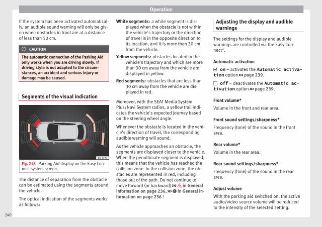
Operation
If the system has been activated automatical-ly, an audible sound warning will only be giv-en when obstacles in front are at a distanceof less than 50 cm.
CAUTION
The automatic connection of the Parking Aidonly works when you are driving slowly. Ifdriving style is not adapted to the circum-stances, an accident and serious injury ordamage may be caused.
Segments of the visual indication
Fig. 218 Parking Aid display on the Easy Con-nect system screen.
The distance of separation from the obstaclecan be estimated using the segments aroundthe vehicle.
The optical indication of the segments worksas follows:
a white segment is dis-played when the obstacle is not withinthe vehicle's trajectory or the directionof travel is in the opposite direction toits location, and it is more than 30 cmfrom the vehicle.
obstacles located in thevehicle's trajectory and which are morethan 30 cm away from the vehicle aredisplayed in yellow.
obstacles that are less than30 cm away from the vehicle are dis-played in red.
Moreover, with the SEAT Media SystemPlus/Navi System radios, a yellow trail indi-cates the vehicle's expected journey basedon the steering wheel angle.
Whenever the obstacle is located in the vehi-cle’s direction of travel, the correspondingaudible warning will sound.
As the vehicle approaches an obstacle, thesegments are displayed closer to the vehicle.When the penultimate segment is displayed,this means that the vehicle has reached thecollision zone. In the collision zone, the ob-stacles are represented in red, includingthose out of the path. Do not continue tomove forward (or backward) ››› in Generalinformation on page 236, ››› in General in-formation on page 236 !
White segments:
Yellow segments:
Red segments:
Adjusting the display and audiblewarnings
The settings for the display and audiblewarnings are controlled via the Easy Con-nect*.
Automatic activation
on – activates the Automatic activa-tion option ››› page 239.
off – deactivates the Automatic ac-tivation option ››› page 239.
Front volume*
Volume in the front and rear area.
Front sound settings/sharpness*
Frequency (tone) of the sound in the frontarea.
Rear volume*
Volume in the rear area.
Rear sound settings/sharpness*
Frequency (tone) of the sound in the reararea.
Adjust volume
With the parking aid switched on, the activeaudio/video source volume will be reducedto the intensity of the selected setting.
240
Driver assistance systems
Error messages
When the Parking Aid is activated or when itis switched on, if a message reporting a Park-ing aid error is displayed on the instrumentpanel, there is a fault in the system.
If the fault doesn't disappear before discon-necting the ignition, next time that parkingaid is engaged in reverse, it will not be indi-cated.
Parking System Plus*
If there is a fault in the parking aid system amessage will appear on the instrument panelindicating the error. In addition the keyLED will blink.
If there is a fault in a sensor, the symbol isdisplayed on the Easy Connect display infront of/behind the vehicle. If a rear sensor isfaulty, only the obstacles in the areas A andB are displayed ››› Fig. 215. If a front sensor
is faulty, only the obstacles in the areas C
and D are displayed.
Have the fault corrected by a specialisedworkshop without delay.
Towing bracket
In vehicles equipped with a towing bracketdevice from the factory, when the trailer isconnected electrically, the Parking Aid rear
sensors will not be activated when reversegear is engaged, when the selector lever isturned to position R or when the button ispressed.
Parking System Plus
The distance to possible obstacles at the rearof the vehicle will not be displayed on thescreen and nor will it be indicated by meansof audible sound signals.
The Easy Connect system screen will only dis-play objects detected at the front, and the ve-hicle's trajectory will be hidden.
Braking while manoeuvring function*3 Only valid with Parking System Plus
The emergency braking function is used tominimise damage in the event of a collision.
Depending on the equipment, if the ParkingAid is active, the braking while manoeuvringfunction activates emergency braking when itdetects an obstacle in the vehicle’s path thatcould cause a collision, driving forwards or inreverse.
The function will not brake if the Parking Aidis activated automatically. For the system tooperate, manoeuvring speed must be greaterthan 2.5 km/h and less than 10 km/h.
Following an intervention, the braking whilemanoeuvring function will be inactive in the
same direction of travel for 5 metres. Oncethe gear is changed, or the selector lever’sposition is changed, the function will be ac-tive again. The Parking Aid’s limitations ap-ply.
The braking while manoeuvring function iscontrolled in the Easy Connect system withthe menu and the SETTINGS andPark and manoeuvre function buttons.
● on – permits the use of the brakingwhile manoeuvring function.
● off – does not permit the use of thebraking while manoeuvring function.
Temporary suppression of emergency brak-ing
● When the function is deactivated with theBraking while manoeuvring button that appears
on the Parking System screen of the EasyConnect system.
● Whenever any of the car doors, rear lid orbonnet are opened.
241
Tech
nica
l dat
aA
dvic
eO
pera
tion
Emer
genc
ies
Saf
ety
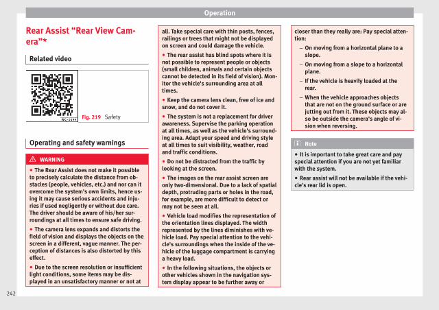
Operation
Rear Assist “Rear View Cam-era”*
Related video
Fig. 219 Safety
Operating and safety warnings
WARNING
● The Rear Assist does not make it possibleto precisely calculate the distance from ob-stacles (people, vehicles, etc.) and nor can itovercome the system's own limits, hence us-ing it may cause serious accidents and inju-ries if used negligently or without due care.The driver should be aware of his/her sur-roundings at all times to ensure safe driving.
● The camera lens expands and distorts thefield of vision and displays the objects on thescreen in a different, vague manner. The per-ception of distances is also distorted by thiseffect.
● Due to the screen resolution or insufficientlight conditions, some items may be dis-played in an unsatisfactory manner or not at
all. Take special care with thin posts, fences,railings or trees that might not be displayedon screen and could damage the vehicle.
● The rear assist has blind spots where it isnot possible to represent people or objects(small children, animals and certain objectscannot be detected in its field of vision). Mon-itor the vehicle's surrounding area at alltimes.
● Keep the camera lens clean, free of ice andsnow, and do not cover it.
● The system is not a replacement for driverawareness. Supervise the parking operationat all times, as well as the vehicle's surround-ing area. Adapt your speed and driving styleat all times to suit visibility, weather, roadand traffic conditions.
● Do not be distracted from the traffic bylooking at the screen.
● The images on the rear assist screen areonly two-dimensional. Due to a lack of spatialdepth, protruding parts or holes in the road,for example, are more difficult to detect ormay not be seen at all.
● Vehicle load modifies the representation ofthe orientation lines displayed. The widthrepresented by the lines diminishes with ve-hicle load. Pay special attention to the vehi-cle's surroundings when the inside of the ve-hicle of the luggage compartment is carryinga heavy load.
● In the following situations, the objects orother vehicles shown in the navigation sys-tem display appear to be further away or
closer than they really are: Pay special atten-tion:
– On moving from a horizontal plane to aslope.
– On moving from a slope to a horizontalplane.
– If the vehicle is heavily loaded at therear.
– When the vehicle approaches objectsthat are not on the ground surface or arejutting out from it. These objects may al-so be outside the camera's angle of vi-sion when reversing.
Note
● It is important to take great care and payspecial attention if you are not yet familiarwith the system.
● Rear assist will not be available if the vehi-cle's rear lid is open.
242

Driver assistance systems
Instructions for use
Fig. 220 On the rear lid handle: location ofthe rear assist camera.
A camera on the rear bumper aids the driverduring reverse parking or manoeuvring››› Fig. 220. The camera image is viewed to-gether with orientation lines projected by thesystem on the Infotainment system screen.The bottom of the screen displays part of thebumper, which can be used by the driver as areference point.
Rear assist settings
Rear assist offers the user the possibility tochange the image's brightness, contrast andcolour settings.
To change these settings:
● Park the vehicle in a safe place.
● Apply the parking brake.
● Switch the ignition on.
● If necessary, switch on the Infotainmentsystem.
● Engage reverse gear or turn the selectorlever to position R.
● Press the function button displayed onthe right of the image.
● Make the desired adjustments on the menuby pressing the –/+ function buttons or bymoving the corresponding scroll button.
Necessary conditions for parking and ma-noeuvring with the rear assist
The system should not be used in the follow-ing cases:
● If the image displayed is not very reliable oris distorted, for example low visibility or dirtylens.
● If the area behind the vehicle is not dis-played very clearly or is incomplete.
● If the vehicle is heavily loaded at the rear.
● If the position and installation angle of thecamera have been changed, e.g. after a rear-end collision. Have the system checked by aspecialised workshop.
Familiarising yourself with the system
To familiarise yourself with the system, theorientation lines and their function, SEAT rec-ommends practising parking and manoeu-vring with the rear assist in a place without
too much traffic or in a car park when thereare good weather and visibility conditions.
Cleaning the camera lens
Keep the camera lens clean and clear of snowand ice:
● Moisten the lens using a normal alcohol-based glass cleaning product and clean thelens with a dry cloth.
● Remove snow using a small brush.
● Use de-icing spray to remove any ice.
CAUTION
● Never use abrasive cleaning products toclean the camera lens.
● Do not use hot or warm water to remove iceor snow from the camera lens. Doing so coulddamage the camera.
243
Tech
nica
l dat
aA
dvic
eO
pera
tion
Emer
genc
ies
Saf
ety
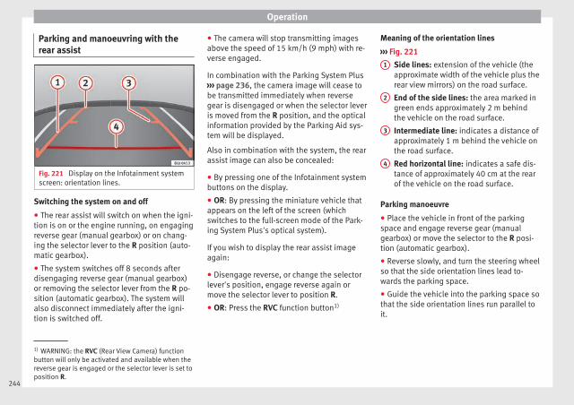
Operation
Parking and manoeuvring with therear assist
Fig. 221 Display on the Infotainment systemscreen: orientation lines.
Switching the system on and off
● The rear assist will switch on when the igni-tion is on or the engine running, on engagingreverse gear (manual gearbox) or on chang-ing the selector lever to the R position (auto-matic gearbox).
● The system switches off 8 seconds afterdisengaging reverse gear (manual gearbox)or removing the selector lever from the R po-sition (automatic gearbox). The system willalso disconnect immediately after the igni-tion is switched off.
● The camera will stop transmitting imagesabove the speed of 15 km/h (9 mph) with re-verse engaged.
In combination with the Parking System Plus››› page 236, the camera image will cease tobe transmitted immediately when reversegear is disengaged or when the selector leveris moved from the R position, and the opticalinformation provided by the Parking Aid sys-tem will be displayed.
Also in combination with the system, the rearassist image can also be concealed:
● By pressing one of the Infotainment systembuttons on the display.
● OR: By pressing the miniature vehicle thatappears on the left of the screen (whichswitches to the full-screen mode of the Park-ing System Plus's optical system).
If you wish to display the rear assist imageagain:
● Disengage reverse, or change the selectorlever's position, engage reverse again ormove the selector lever to position R.
● OR: Press the RVC function button1)
Meaning of the orientation lines
››› Fig. 221
Side lines: extension of the vehicle (theapproximate width of the vehicle plus therear view mirrors) on the road surface.
End of the side lines: the area marked ingreen ends approximately 2 m behindthe vehicle on the road surface.
Intermediate line: indicates a distance ofapproximately 1 m behind the vehicle onthe road surface.
Red horizontal line: indicates a safe dis-tance of approximately 40 cm at the rearof the vehicle on the road surface.
Parking manoeuvre
● Place the vehicle in front of the parkingspace and engage reverse gear (manualgearbox) or move the selector to the R posi-tion (automatic gearbox).
● Reverse slowly, and turn the steering wheelso that the side orientation lines lead to-wards the parking space.
● Guide the vehicle into the parking space sothat the side orientation lines run parallel toit.
1
2
3
4
1) WARNING: the RVC (Rear View Camera) functionbutton will only be activated and available when thereverse gear is engaged or the selector lever is set toposition R.
244
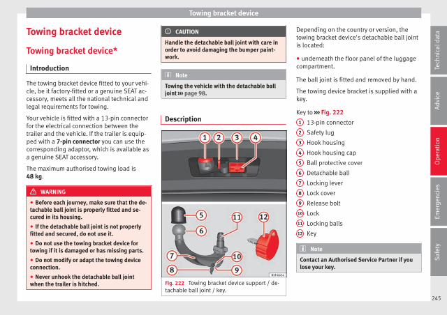
Towing bracket device
Towing bracket device
Towing bracket device*
Introduction
The towing bracket device fitted to your vehi-cle, be it factory-fitted or a genuine SEAT ac-cessory, meets all the national technical andlegal requirements for towing.
Your vehicle is fitted with a 13-pin connectorfor the electrical connection between thetrailer and the vehicle. If the trailer is equip-ped with a 7-pin connector you can use thecorresponding adaptor, which is available asa genuine SEAT accessory.
The maximum authorised towing load is48 kg.
WARNING
● Before each journey, make sure that the de-tachable ball joint is properly fitted and se-cured in its housing.
● If the detachable ball joint is not properlyfitted and secured, do not use it.
● Do not use the towing bracket device fortowing if it is damaged or has missing parts.
● Do not modify or adapt the towing deviceconnection.
● Never unhook the detachable ball jointwhen the trailer is hitched.
CAUTION
Handle the detachable ball joint with care inorder to avoid damaging the bumper paint-work.
Note
Towing the vehicle with the detachable balljoint ››› page 98.
Description
Fig. 222 Towing bracket device support / de-tachable ball joint / key.
Depending on the country or version, thetowing bracket device's detachable ball jointis located:
● underneath the floor panel of the luggagecompartment.
The ball joint is fitted and removed by hand.
The towing device bracket is supplied with akey.
Key to ››› Fig. 222
13-pin connector
Safety lug
Hook housing
Hook housing cap
Ball protective cover
Detachable ball
Locking lever
Lock cover
Release bolt
Lock
Locking balls
Key
Note
Contact an Authorised Service Partner if youlose your key.
1
2
3
4
5
6
7
8
9
10
11
12
245
Tech
nica
l dat
aA
dvic
eO
pera
tion
Emer
genc
ies
Saf
ety
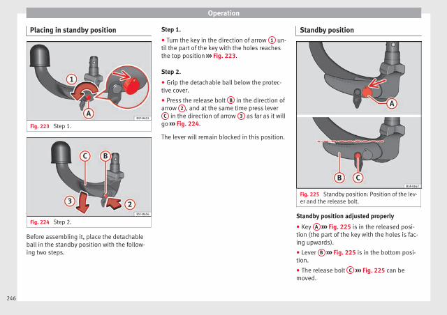
Operation
Placing in standby position
Fig. 223 Step 1.
Fig. 224 Step 2.
Before assembling it, place the detachableball in the standby position with the follow-ing two steps.
Step 1.
● Turn the key in the direction of arrow 1 un-til the part of the key with the holes reachesthe top position ››› Fig. 223.
Step 2.
● Grip the detachable ball below the protec-tive cover.
● Press the release bolt B in the direction ofarrow 2 , and at the same time press lever
C in the direction of arrow 3 as far as it willgo ››› Fig. 224.
The lever will remain blocked in this position.
Standby position
Fig. 225 Standby position: Position of the lev-er and the release bolt.
Standby position adjusted properly
● Key A ››› Fig. 225 is in the released posi-tion (the part of the key with the holes is fac-ing upwards).
● Lever B ››› Fig. 225 is in the bottom posi-tion.
● The release bolt C ››› Fig. 225 can bemoved.
246
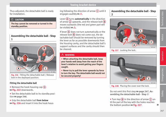
Towing bracket device
Thus adjusted, the detachable ball is readyfor installation.
CAUTION
The key cannot be removed or turned in thestandby position.
Assembling the detachable ball - Step1
Fig. 226 Fitting the detachable ball / Releasebolt in the deployed position.
Fitting the detachable ball
● Remove the hook housing cap 4
››› Fig. 222 downwards.
● Set the detachable ball to its standby posi-tion ››› page 246.
● Grip the detachable ball from below››› Fig. 226 and insert it into the hook hous-
ing following the direction of arrow 1 until itengages audibly ››› .
Lever A turns automatically in the directionof arrow 2 upwards, and the release bolt B
moves outwards (the red and green part willbe visible) ››› .
If lever A does not turn automatically or therelease bolt B does not come out, the de-tachable ball should be removed by turningthe lever as far as possible downwards fromthe housing cavity, and the detachable ball'ssupport surfaces and the cavity should thenbe cleaned.
WARNING
● When attaching the detachable ball, keepyour hands well away from the reach of thelever's rotation to avoid getting your fingerscaught.
● Never try to pull the lever upwards by forceto turn the key. The detachable ball would notbe secured properly!
Assembling the detachable ball - Step2
Fig. 227 Locking the lock.
Fig. 228 Placing the cover over the lock.
Do not omit this first step ››› page 247, As-sembling the detachable ball - Step 1!
● Turn key A in the direction of arrow 1 un-til the part of the key with the holes reachesthe bottom position ››› Fig. 227. »
247
Tech
nica
l dat
aA
dvic
eO
pera
tion
Emer
genc
ies
Saf
ety

Operation
● Remove the key in the direction of arrow2 .
● Place cover B in the lock in the directionof arrow 3 ››› Fig. 228 ››› .
● Check that the detachable ball is secure››› page 248.
CAUTION
● After removing the key, always place thecover over the lever's lock. If the lock be-comes soiled it will be impossible to insertthe key.
● Keep the towing bracket device's housingcavity clean at all times. Dirtiness can pre-vent the detachable ball from being properlysecured!
● If the detachable ball is removed, alwaysplace the cap on the hook's housing.
Checking proper attachment
Fig. 229 Detachable ball properly attached.
Whenever you go to use the detachable ball,make sure that it is properly attached first.
Detachable ball properly attached.
● The detachable ball will not fall out of thehousing cavity after a major “knock or jerk”.
● Lever A ››› Fig. 229 is fully raised.
● The release bolt B ››› Fig. 229 is stickingfully out (the red and green part is visible).
● The key has been removed.
● Cover C ››› Fig. 229 is placed over the lock.
WARNING
● When removing the detachable ball, keepyour hands well away from the reach of thelever's rotation to avoid getting your fingerscaught.
● The towing bracket device should only beused if the detachable ball has been properlylocked!
Removing the detachable ball - Step 1
Fig. 230 Removing the lock cover.
Fig. 231 Releasing the lock.
● Remove cover A from the lock in the direc-tion of arrow 1 ››› Fig. 230.
248
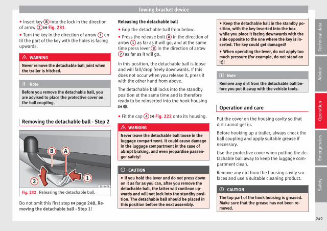
Towing bracket device
● Insert key B into the lock in the directionof arrow 2 ››› Fig. 231.
● Turn the key in the direction of arrow 3 un-til the part of the key with the holes is facingupwards.
WARNING
Never remove the detachable ball joint whenthe trailer is hitched.
Note
Before you remove the detachable ball, youare advised to place the protective cover onthe ball coupling.
Removing the detachable ball - Step 2
Fig. 232 Releasing the detachable ball.
Do not omit this first step ››› page 248, Re-moving the detachable ball - Step 1!
Releasing the detachable ball
● Grip the detachable ball from below.
● Press the release bolt A in the direction ofarrow 1 as far as it will go, and at the sametime press lever B in the direction of arrow
2 as far as it will go.
In this position, the detachable ball is looseand will fall/drop freely downwards. If thisdoes not occur when you release it, press itwith the other hand from above.
The detachable ball locks into the standbyposition at the same time and is thereforeready to be reinserted into the hook housing››› .
● Fit the cap 4 ››› Fig. 222 onto its housing.
WARNING
Never leave the detachable ball loose in theluggage compartment. It could cause damagein the luggage compartment in the case ofabrupt braking, and even jeopardise passen-ger safety!
CAUTION
● If you hold the lever and do not press downon it as far as you can, after you remove thedetachable ball, the latter will continue up-wards and will not lock into the standby posi-tion. The detachable ball should be placed inthis position before the next assembly.
● Keep the detachable ball in the standby po-sition, with the key inserted into the boxwhile you place it facing downwards with theside opposite to the one where the key is in-serted. The key could get damaged!
● When operating the lever, do not apply toomuch pressure (for example, do not stand onit)!
Note
Remove any dirt from the detachable ball be-fore you put it away with the vehicle tools.
Operation and care
Put the cover on the housing cavity so thatdirt cannot get in.
Before hooking up a trailer, always check theball coupling and apply suitable grease ifnecessary.
Use the protective cover when putting the de-tachable ball away to keep the luggage com-partment clean.
Remove any dirt from the housing cavity sur-faces and use a suitable cleaning product.
CAUTION
The top part of the hook housing is greased.Make sure that the grease has not been re-moved.
249
Tech
nica
l dat
aA
dvic
eO
pera
tion
Emer
genc
ies
Saf
ety
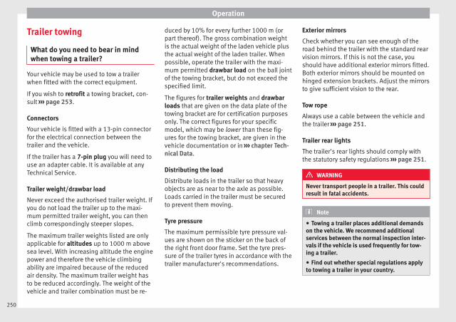
Operation
Trailer towing
What do you need to bear in mindwhen towing a trailer?
Your vehicle may be used to tow a trailerwhen fitted with the correct equipment.
If you wish to retrofit a towing bracket, con-sult ››› page 253.
Connectors
Your vehicle is fitted with a 13-pin connectorfor the electrical connection between thetrailer and the vehicle.
If the trailer has a 7-pin plug you will need touse an adapter cable. It is available at anyTechnical Service.
Trailer weight/drawbar load
Never exceed the authorised trailer weight. Ifyou do not load the trailer up to the maxi-mum permitted trailer weight, you can thenclimb correspondingly steeper slopes.
The maximum trailer weights listed are onlyapplicable for altitudes up to 1000 m abovesea level. With increasing altitude the enginepower and therefore the vehicle climbingability are impaired because of the reducedair density. The maximum trailer weight hasto be reduced accordingly. The weight of thevehicle and trailer combination must be re-
duced by 10% for every further 1000 m (orpart thereof). The gross combination weightis the actual weight of the laden vehicle plusthe actual weight of the laden trailer. Whenpossible, operate the trailer with the maxi-mum permitted drawbar load on the ball jointof the towing bracket, but do not exceed thespecified limit.
The figures for trailer weights and drawbarloads that are given on the data plate of thetowing bracket are for certification purposesonly. The correct figures for your specificmodel, which may be lower than these fig-ures for the towing bracket, are given in thevehicle documentation or in ››› chapter Tech-nical Data.
Distributing the load
Distribute loads in the trailer so that heavyobjects are as near to the axle as possible.Loads carried in the trailer must be securedto prevent them moving.
Tyre pressure
The maximum permissible tyre pressure val-ues are shown on the sticker on the back ofthe right front door frame. Set the tyre pres-sure of the trailer tyres in accordance with thetrailer manufacturer's recommendations.
Exterior mirrors
Check whether you can see enough of theroad behind the trailer with the standard rearvision mirrors. If this is not the case, youshould have additional exterior mirrors fitted.Both exterior mirrors should be mounted onhinged extension brackets. Adjust the mirrorsto give sufficient vision to the rear.
Tow rope
Always use a cable between the vehicle andthe trailer ››› page 251.
Trailer rear lights
The trailer's rear lights should comply withthe statutory safety regulations ››› page 251.
WARNING
Never transport people in a trailer. This couldresult in fatal accidents.
Note
● Towing a trailer places additional demandson the vehicle. We recommend additionalservices between the normal inspection inter-vals if the vehicle is used frequently for tow-ing a trailer.
● Find out whether special regulations applyto towing a trailer in your country.
250
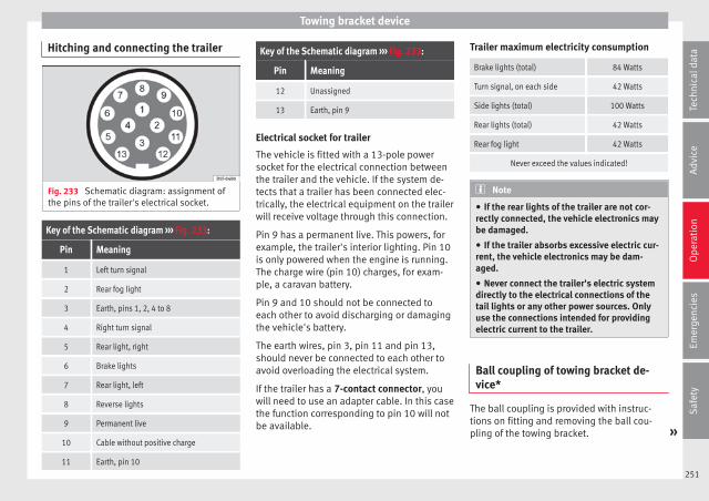
Towing bracket device
Hitching and connecting the trailer
Fig. 233 Schematic diagram: assignment ofthe pins of the trailer's electrical socket.
Key of the Schematic diagram ››› Fig. 233:
Pin Meaning
1 Left turn signal
2 Rear fog light
3 Earth, pins 1, 2, 4 to 8
4 Right turn signal
5 Rear light, right
6 Brake lights
7 Rear light, left
8 Reverse lights
9 Permanent live
10 Cable without positive charge
11 Earth, pin 10
Key of the Schematic diagram ››› Fig. 233:
Pin Meaning
12 Unassigned
13 Earth, pin 9
Electrical socket for trailer
The vehicle is fitted with a 13-pole powersocket for the electrical connection betweenthe trailer and the vehicle. If the system de-tects that a trailer has been connected elec-trically, the electrical equipment on the trailerwill receive voltage through this connection.
Pin 9 has a permanent live. This powers, forexample, the trailer's interior lighting. Pin 10is only powered when the engine is running.The charge wire (pin 10) charges, for exam-ple, a caravan battery.
Pin 9 and 10 should not be connected toeach other to avoid discharging or damagingthe vehicle's battery.
The earth wires, pin 3, pin 11 and pin 13,should never be connected to each other toavoid overloading the electrical system.
If the trailer has a 7-contact connector, youwill need to use an adapter cable. In this casethe function corresponding to pin 10 will notbe available.
Trailer maximum electricity consumption
Brake lights (total) 84 Watts
Turn signal, on each side 42 Watts
Side lights (total) 100 Watts
Rear lights (total) 42 Watts
Rear fog light 42 Watts
Never exceed the values indicated!
Note
● If the rear lights of the trailer are not cor-rectly connected, the vehicle electronics maybe damaged.
● If the trailer absorbs excessive electric cur-rent, the vehicle electronics may be dam-aged.
● Never connect the trailer's electric systemdirectly to the electrical connections of thetail lights or any other power sources. Onlyuse the connections intended for providingelectric current to the trailer.
Ball coupling of towing bracket de-vice*
The ball coupling is provided with instruc-tions on fitting and removing the ball cou-pling of the towing bracket. »
251
Tech
nica
l dat
aA
dvic
eO
pera
tion
Emer
genc
ies
Saf
ety

Operation
WARNING
The towing bracket ball coupling must bestored securely in the luggage compartmentto prevent them being flung through the vehi-cle and causing injury.
Note
● By law, the ball coupling must be removedif a trailer is not being towed if it obscuresthe number plate.
Driving with a trailer
Fig. 234 Turn the 13-pin connector.
Before driving
● Grip the 13-pin connector at area A andremove it in the direction of the arrow››› Fig. 234.
● Remove the protective cover 5 ››› Fig. 222upwards.
After driving
● Grip the 13-pin connector at area A andinsert it in the opposite direction to the arrow››› Fig. 234.
● Fit the protective cover 5 ››› Fig. 222 onthe ball coupling.
Safety lug
The safety lug B ››› Fig. 234 is used to hookup the trailer's retainer cable.
On hooking it up to the safety lug, the retain-er cable should have slack in all the trailerpositions with respect to the vehicle (sharpbends, reverse gear, etc.).
Headlights
The front part of the vehicle may be raisedwhen the trailer is connected and the lightmay dazzle the rest of the traffic.
Adapt the height of the headlights using theheadlight range rotary adjuster1).
WARNING
● Never use the safety lug to tow!
● Adjust your speed to suit the road and traf-fic conditions.
● All work on the electrical system must becarried out only by specialised workshops.
● Never connect the trailer's electric systemto the electrical connections of the rear lightsor any other power sources.
● After hooking up the trailer and connectingthe socket, check that all the trailer's rearlights are working properly.
Note
● If there is any fault in the trailer's lighting,check the fuses in the instrument panel fusebox ››› page 58.
● The contact between the retainer cable andthe safety lug may give rise to mechanicalwear in the lug's surface protection. Thiswear will not prevent the safety lug from op-erating properly or cause any fault and is ex-cluded from the warranty.
● When connecting and disconnecting thetrailer, the towing vehicle's handbrakeshould be applied.
1) This does not apply for vehicles with bi-xenonheadlights.
252
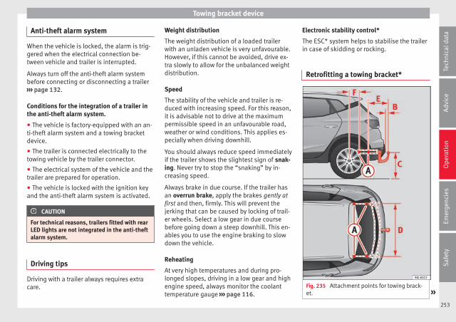
Towing bracket device
Anti-theft alarm system
When the vehicle is locked, the alarm is trig-gered when the electrical connection be-tween vehicle and trailer is interrupted.
Always turn off the anti-theft alarm systembefore connecting or disconnecting a trailer››› page 132.
Conditions for the integration of a trailer inthe anti-theft alarm system.
● The vehicle is factory-equipped with an an-ti-theft alarm system and a towing bracketdevice.
● The trailer is connected electrically to thetowing vehicle by the trailer connector.
● The electrical system of the vehicle and thetrailer are prepared for operation.
● The vehicle is locked with the ignition keyand the anti-theft alarm system is activated.
CAUTION
For technical reasons, trailers fitted with rearLED lights are not integrated in the anti-theftalarm system.
Driving tips
Driving with a trailer always requires extracare.
Weight distribution
The weight distribution of a loaded trailerwith an unladen vehicle is very unfavourable.However, if this cannot be avoided, drive ex-tra slowly to allow for the unbalanced weightdistribution.
Speed
The stability of the vehicle and trailer is re-duced with increasing speed. For this reason,it is advisable not to drive at the maximumpermissible speed in an unfavourable road,weather or wind conditions. This applies es-pecially when driving downhill.
You should always reduce speed immediatelyif the trailer shows the slightest sign of snak-ing. Never try to stop the “snaking” by in-creasing speed.
Always brake in due course. If the trailer hasan overrun brake, apply the brakes gently atfirst and then, firmly. This will prevent thejerking that can be caused by locking of trail-er wheels. Select a low gear in due coursebefore going down a steep downhill. This en-ables you to use the engine braking to slowdown the vehicle.
Reheating
At very high temperatures and during pro-longed slopes, driving in a low gear and highengine speed, always monitor the coolanttemperature gauge ››› page 116.
Electronic stability control*
The ESC* system helps to stabilise the trailerin case of skidding or rocking.
Retrofitting a towing bracket*
Fig. 235 Attachment points for towing brack-et. »
253
Tech
nica
l dat
aA
dvic
eO
pera
tion
Emer
genc
ies
Saf
ety

Operation
If a towing bracket is to be fitted after the ve-hicle is purchased, this must be completedaccording to the instructions of the towingbracket manufacturer.
The attachment points for the towing bracketA are on the lower part of the vehicle.
The distance between the centre of the ballcoupling and the ground should never belower than the indicated value, even with afully loaded vehicle and including the maxi-mum drawbar load.
Elevation values for securing the towingbracket:
Elevation values for securing the towing bracket:
B 65 mm (minimum)
C 350 mm to 420 mm (fully laden vehicle)
D 1,033 mm
E 322 mm
F 338 mm
Fitting a towing bracket
● Driving with a trailer involves an extra effortfor the vehicle. Therefore, before fitting atowing bracket, please contact a TechnicalService to check whether your cooling systemneeds modification.
● The legal requirements in your countrymust be observed (e.g. the fitting of a sepa-rate control lamp).
● Certain vehicle components, e.g. the rearbumper, must be removed and reinstalled.The towing bracket securing bolts must betightened using a torque wrench, and a pow-er socket must be connected to the vehicleelectrical system. This requires specialisedknowledge and tools.
● Figures in the illustration show the eleva-tion value and the attachment points whichmust be considered if you are retrofitting atowing bracket.
WARNING
The towing brackets should be fitted at a spe-cialised workshop.
● If the towing bracket is incorrectly instal-led, there is a serious danger of accident.
● For your own safety, please observe the towbracket manufacturer's instructions.
CAUTION
● If the power socket is incorrectly installed,this could cause damage to the vehicle elec-trical system.
Note
● SEAT recommends that the towing hooksbe fitted at a specialised workshop. Consultyour SEAT dealer in case additional modifica-tions to your vehicle are necessary.
● Due to the specific design of the exhaust,the fitting of a conventional towing hook is
not recommended for some sportier versions.Please consult your Technical Service.
254

Care and maintenance
Advice
Care and maintenance
Accessories and modificationsto the vehicle
Accessories, replacement of parts andmodifications
Your vehicle is designed to offer a highstandard of active and passive safety.
Before purchasing accessories and parts,and before making technical changes to yourvehicle, we recommend that you consult yourTechnical Service.
SEAT dealerships will be happy to provideyou with the latest information about theuse, legal requirements and recommenda-tions from the manufacturer regarding acces-sories and spare parts.
We recommend you use only SEAT ApprovedAccessories® and SEAT Approved SpareParts®. This way, SEAT can guarantee thatthe product in question is suitable, reliableand safe. SEAT Technical Services have thenecessary experience and facilities to ensurethat parts are correctly and professionally in-stalled.
Despite a continuous observation of the mar-ket, SEAT is not able to assess the reliability,safety and suitability of parts that SEAT hasnot approved. For this reason, SEAT cannotassume responsibility for any non-genuineparts used, even if these parts have been ap-proved by an official testing agency or arecovered by an official approval certificate.
Any retro-fitted equipment which has a directimpact on the driver's control of the vehicle,such as a cruise control system or electroni-cally-controlled suspension, must be ap-proved by SEAT for use in your vehicle andbear the e mark (the European Union's au-thorisation symbol).
If any additional electrical devices are fittedwhich do not serve to control the vehicle it-self, such as refrigerator boxes, laptops orventilator fans, they must bear the CE mark(European Union manufacturer conformitydeclaration).
WARNING
Accessories, for example telephone holdersor cup holders, should never be fitted on thecovers, or within the working range, of theairbags. Otherwise, there is a danger of in-jury if the airbag is triggered in an accident.
Modifications
Modifications must always be carried out ac-cording to our specifications. Unauthorisedmodifications to the electronic componentsor software in the vehicle may cause malfunc-tions. Due to the way the electronic compo-nents are linked together in networks, otherindirect systems may be affected by thefaults. This can seriously impair safety, leadto excessive wear of components, and alsoinvalidate your vehicle registration docu-ments.
SEAT Technical Services cannot be held liablefor any damage caused by modificationsand/or work incorrectly performed. For thisreason, we recommend having all work per-formed by a SEAT Technical Service usingSEAT® Original Spare Parts.
WARNING
Any type of work or modification performedincorrectly on your vehicle can lead to mal-functions and can cause accidents.
Radio transmitters and office equip-ment
Radio transmitters (fixed installation)
Any retrofit installations of radio transmittersin the vehicle require prior approval. SEATgenerally authorises in-vehicle installations »
255
Tech
nica
l dat
aA
dvic
eO
pera
tion
Emer
genc
ies
Saf
ety

Advice
of approved types of radio transmitters provi-ded that:
● The aerial is installed correctly.
● The aerial is installed on the exterior of thevehicle (and shielded cables are used togeth-er with non-reflective aerial trimming).
● The effective transmitting power does notexceed 10 Watts at the aerial base.
A SEAT Official Service and specialised work-shop will be able to inform you about optionsfor installing and operating radio transmitterswith a higher transmitting power.
Mobile radio transmitters
Commercial mobile telephones or radioequipment might interfere with the electron-ics of your vehicle and cause malfunctions.This may be due to:
● No external aerial.
● External aerial incorrectly installed.
● Transmitting power more than 10 W.
You must, therefore, do not operate portablemobile telephones or radio equipment insidethe vehicle without a properly installed exter-nal aerial ››› .
Please note also that the maximum range ofthe equipment can only be achieved with anexternal aerial.
Business equipment
Retrofit installation of business or privateequipment in the vehicle is permitted, provi-ded the equipment cannot interfere with thedriver's immediate control of the vehicle andthat any such equipment carries the mark.Any retrofit equipment that could influencethe driver's control of the vehicle must have atype approval for your vehicle and must carrythe e mark.
WARNING
Mobile telephones or radio equipment whichis operated inside the vehicle without a prop-erly installed external aerial can create exces-sive magnetic fields that could cause a healthhazard.
Note
● The posterior fitting of electric and elec-tronic equipment in this vehicle affects its li-cence and could lead to the withdrawal of thevehicle registration document under certaincircumstances.
● Please use the mobile telephone/radio op-erating instructions.
Care and cleaning
General notes
Vehicle maintenance
Regular care and washing help to maintainthe value of the vehicle. This may also be oneof the requirements for acknowledging war-ranty claims in the event of bodywork corro-sion or paint defects.
The best way to protect your vehicle againstthe harmful effects of the environment isthrough correct maintenance and frequentwashing. The longer substances such as in-sect remains, bird droppings, resinous treesap, road dirt, industrial deposits, tar, soot orroad salt and other aggressive materials re-main on the vehicle, the more damage theydo to the paintwork. High temperatures, forinstance in strong sunlight, further intensifythe corrosive effect.
After winter, a period when salt is put on theroads, it is important to have the undersideof the vehicle washed thoroughly.
Products for vehicle maintenance
Car-care products are available in your Tech-nical Services. Keep the product instructionsuntil you have used them up.
256
Care and maintenance
WARNING
● Car-care products can be toxic. Because ofthis, they must always be kept closed in theiroriginal container. Keep them out of the reachof children. Failure to comply could result inpoisoning.
● Always read and observe the instructionsand warnings on the package before usingcar-care products. Improper use could causehealth problems or damage the vehicle. Theuse of certain products may produce noxiousvapours; they should be used in well ventila-ted areas.
● Never use fuel, turpentine, engine oil, nailvarnish remover or other volatile fluids.These are toxic and highly flammable. Risk offire and explosion.
● Before washing your vehicle, or carryingout any maintenance, switch the engine off,apply the handbrake firmly and remove thekey from the ignition.
CAUTION
Never attempt to remove dirt, mud or dust ifthe surface of the vehicle is dry. Never use adry cloth or sponge for cleaning purposes.This could damage the paintwork or the win-dows of your vehicle. Soak dirt, mud or dustwith plenty of water.
For the sake of the environment
● When purchasing car care products, try toselect ones that are not harmful to the envi-ronment.
● The waste from car-care products shouldnot be disposed of with ordinary householdwaste. Observe the disposal information onthe package.
Care of the vehicle exterior
Automatic car wash tunnel
The vehicle paintwork is so durable that thevehicle can normally be washed withoutproblems in an automatic car wash tunnel.However, the paintwork wear depends to alarge extent on the kind of the car wash tun-nel, the brushes used, its water filtering andthe type of cleaning and preservative prod-ucts.
Before going through a car wash, be sure totake the usual precautions such as closingthe windows. There is nothing to note apartfrom that.
If the vehicle has special accessories such asspoilers or a roof rack or two-way radio aerial,etc., it is advisable to consult the car washtunnel operator first.
After washing, the brakes could take sometime to respond as the brake discs and padscould be wet, or even frozen in winter. “Dry”the brakes by braking several times.
WARNING
Water, ice and salt on the brake system canreduce braking effectiveness. Risk of acci-dent.
Hand-washing
Vehicle washing
– First soften the dirt and rinse it off with wa-ter.
– Clean your vehicle from top to bottom witha soft sponge, a glove or a brush. Use verylight pressure.
– Rinse the sponge or glove often with cleanwater.
– Special car shampoo should only be usedfor very stubborn dirt.
– Leave the wheels, sill panels etc. until last,using a different sponge or glove.
– Rinse the vehicle thoroughly with water.
– Dry the vehicle surface gently with a cha-mois leather.
– In cold temperature, dry the rubber sealsand their surfaces to prevent them from »
257
Tech
nica
l dat
aA
dvic
eO
pera
tion
Emer
genc
ies
Saf
ety
Advice
freezing. Apply silicone spray to the rubberseals.
After washing the vehicle
– After washing, avoid sudden and sharpbraking. “Dry” the brakes by braking sever-al times.
WARNING
● Wash your vehicle with the ignition switch-ed off.
● Protect your hands and arms from cuts onsharp metal edges when cleaning the under-body, the inside of the wheel housings etc.Risk of injury.
● Water, ice and salt on the brake system canreduce braking effectiveness. Risk of acci-dent.
CAUTION
● Never remove dirt, mud or dust if the vehi-cle surface is dry. Never use a dry cloth orsponge for cleaning purposes. This couldscratch the paintwork or glass on your vehi-cle.
● Washing the vehicle in low temperatures:when washing the vehicle with a hose, do notdirect water into the lock cylinders or thegaps around the doors. Risk of freezing.
For the sake of the environment
To protect the environment, the vehicleshould be washed only in specially providedwash bays, to prevent toxic, oil-laden wastewater from entering the sewer system. Insome places, washing vehicles outside washbays is prohibited.
Note
Do not wash the vehicle in direct sunlight.
Washing the vehicle with a high pres-sure cleaner
Be particularly careful when using a highpressure cleaner!
– Always observe the instructions for thehigh-pressure cleaner, particularly thoseconcerning the pressure and the sprayingdistance.
– Increase the spraying distance for soft ma-terials and painted bumpers.
– Do not use a high pressure cleaner to re-move ice or snow from windows››› page 259.
– Never use concentrated jet nozzles (“rotat-ing jets”) ››› .
– After washing, avoid sudden and sharpbraking. “Dry” the brakes by braking sever-al times ››› page 174.
WARNING
● Never wash tyres with a concentrated jet(“rotating nozzle”). Even at large sprayingdistances and short cleaning times, damagecan occur to the tyres. This may cause an ac-cident.
● Water, ice and salt on the brake system canreduce braking effectiveness. Risk of acci-dent.
CAUTION
● Do not use water hotter than +60°C(+140°F). This could damage the vehicle.
● To avoid damage to the vehicle, keep a suf-ficient distance from sensitive materials suchas flexible hoses, plastic, soundproofing ma-terial, etc. This also applies to bumpers pain-ted in the colour of the bodywork. The closerthe nozzle is to the surface, the greater thewear on the material.
Factory-fitted adhesive sheets
The following indications should be taken in-to account to avoid damaging adhesivesheets:
● Do not use high pressure cleaners.
258
Care and maintenance
● Do not use scrapers to remove ice or snowfrom the sheets.
● Do not polish the adhesive sheets.
● Do not use dirty cloths or sponges.
● It is preferable to wash them with a softsponge and gentle neutral soap.
Sensors and camera lenses
● Use a small brush to remove snow and ade-icer spray to remove ice.
● Clean the sensors with a solvent-free prod-uct and a soft, dry cloth.
● Moisten the camera lens using a standardalcohol-based glass cleaning agent andclean the lens with a dry cloth.
CAUTION
● When you clean the vehicle with a pressurewasher:
– Stay a suitable distance from the sensorson the front and rear bumpers.
– Do not clean the camera lenses or sur-rounding area with the pressure washer.
● Never use warm or hot water to removesnow and ice from the reverse camera lens,as it could crack the lens.
● Never use abrasive cleaning agents on thelens.
Vehicle paint maintenance
Regular waxing protects the paintwork.
You need to apply wax to your vehicle if waterdoes not form small drops and run off thepaintwork when it is clean.
Good quality hard wax products are availableat your Technical Service.
Regular wax applications help to protect thepaintwork from environmental contaminants››› page 256. It is also effective in protectingagainst minor scratches.
Even if a wax solution is used regularly in thevehicle washing tunnel, it is advisable to pro-tect the paint with a hard wax coating at leasttwice a year.
Polishing the paintwork
Polishing is only necessary if the paint haslost its shine, and the gloss cannot bebrought back by applying wax. Polishingproducts can be purchased in your TechnicalService.
The vehicle must be waxed after polishing ifthe polish used does not contain wax com-pounds to seal the paint ››› page 259, Vehiclepaint maintenance.
CAUTION
To prevent damage to the paintwork:
● Do not use polishes and hard wax on pain-ted parts with a matt finish or on plasticparts.
● Do not polish your vehicle in a sandy ordusty environment.
Caring for plastic parts
If normal washing fails to clean plastic parts,clean them with approved solvent-free plas-tic cleaning and care products.
CAUTION
● The use of liquid air freshener directly overthe air vents of the vehicle may damage theplastic parts if the liquid is accidentally spil-led.
● Cleaning products which contain solventswill damage the material.
Cleaning of windows and mirrors
Cleaning windows
– Moisten the windows with commerciallyavailable, alcohol based glass cleaner.
– Dry the windows with a clean chamoisleather or a lint-free cloth. »
259
Tech
nica
l dat
aA
dvic
eO
pera
tion
Emer
genc
ies
Saf
ety
Advice
Removing snow
– Use a small brush to remove snow from thewindows and mirrors.
Removing ice
– Use a de-icer spray.
Use a clean cloth or chamois leather to drythe windows. The chamois leathers used onpainted surfaces are not suitable to cleanwindows because they are soiled with waxdeposits which could smear the windows.
If possible, use a de-icing spray to removeice. If you use an ice scraper, push it in onedirection only without swinging it.
Use window cleaner or a silicone remover toclean rubber, oil, grease and silicone depos-its off.
Wax deposits can only be removed with aspecial cleaner available at your TechnicalService. Wax deposits on the windscreencould cause the wiper blades to judder. Add-ing a window cleaner that dissolves wax tothe windscreen washer fluid prevents wiperblades from juddering, but wax deposits arenot removed.
CAUTION
● Never use warm or hot water to removesnow and ice from windows and mirrors. Thiscould cause the glass to crack!
● The heating element for the rear window islocated on the inner side of the window. Toprevent damage, do not put stickers over theheating elements on the inside of the win-dow.
Cleaning windscreen wiper blades
Clean wiper blades improve visibility.
1. Use a soft cloth to remove dust and dirtfrom the windscreen wiper blades.
2. Use window cleaner to clean the wind-screen wiper blades. Use a sponge or acloth to remove stubborn dirt.
Care of rubber seals
If rubber seals are well looked after, they willnot freeze so quickly.
1. Use a soft cloth to remove dust and dirtfrom the rubber seals.
2. Apply a specialist care product to the rub-ber seals.
The rubber strips on the doors, windows, etc.will remain pliable and last longer if they aretreated with a suitable rubber care productfrom time to time (for example siliconespray).
Caring for rubber seals will also prevent pre-mature ageing and leaks. The doors will beeasier to open. If rubber seals are well lookedafter, they will not freeze so quickly in winter.
Door lock cylinder
The door lock cylinders can freeze up in win-ter.
To de-ice the lock cylinders you should onlyuse spray with lubricating and anti-corrosiveproperties.
Cleaning chrome parts
1. Clean chrome parts with a damp cloth.
2. Polish chrome parts with a soft, dry cloth.
If this does not provide satisfying results, usea specialist chrome cleaning product.Chrome cleaning products will remove stainsfrom the surface.
CAUTION
To prevent scratching chrome surfaces:
● Never use an abrasive cleaning product onchrome.
● Do not clean or polish chrome parts in asandy or dusty environment.
260
Care and maintenance
Steel wheel rims
– Clean steel wheel rims regularly using aseparate sponge.
Use an industrial cleaner to remove brakedust. Any damage to the paint on steel wheelrims should be repaired before starting torust.
WARNING
● Never wash tyres with a cylindrical jet. Evenat large spraying distances and short clean-ing times, damage can occur to the tyres.This may cause an accident.
● Water, ice and salt on the brake system canreduce braking effectiveness. Risk of acci-dent. Directly after washing, avoid suddenand sharp braking. “Dry” the brakes by brak-ing several times ››› page 174, Braking ca-pacity and braking distance.
Alloy wheel rims
Every two weeks
– Wash salt and brake dust from alloywheels.
– Use an acid free detergent to clean thewheel rims.
Every 3 months
– Apply a hard wax compound to the wheels.
Alloy wheels require regular attention to pre-serve their appearance. If road salt and brakedust are not often removed, the aluminiumfinish will be impaired.
Always use an acid-free detergent for alloywheel rims.
Car polish or other abrasive agents shouldnot be used for maintaining the rims. If theprotective coating is damaged, e.g. by flyingstones, the damaged area should be re-paired immediately.
WARNING
Observe the safety warnings ››› in Steelwheel rims on page 261.
Vehicle underbody protection
The vehicle underbody is coated to protect itfrom chemical and mechanical damage.
The protective coating can be damaged whendriving. We recommend that you check theprotective coating under the body and on therunning gear, and retouch it if necessary, be-fore and after the winter season.
We recommend that you go to your TechnicalService to carry out repair work and addition-al anti-corrosion work.
WARNING
Do not apply underseal or anti-corrosioncoatings to the exhaust pipes, catalytic con-verter or the heat shields on the exhaust sys-tem. The heat of the exhaust system or theengine could cause them to ignite. Risk offire.
Cleaning engine compartment
Take special care when cleaning the enginecompartment.
Anti-corrosion treatment
The engine compartment and the surface ofthe power unit are given anti-corrosion treat-ment at the factory.
Good corrosion protection is particularly im-portant in winter when the vehicle is fre-quently driven on salted roads. To preventthe salt corroding the vehicle, the entire en-gine compartment should be thoroughlycleaned before and after winter.
Technical Services have the proper productsfor cleaning and preservation as well as thenecessary workshop equipment. For this rea-son, we recommend having this work per-formed by them.
The anti-corrosion protection is usually re-moved if the engine compartment is cleanedwith grease removing solutions, or if you »
261
Tech
nica
l dat
aA
dvic
eO
pera
tion
Emer
genc
ies
Saf
ety
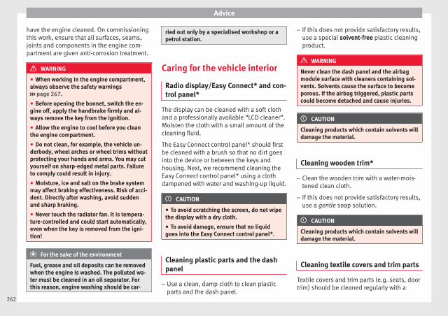
Advice
have the engine cleaned. On commissioningthis work, ensure that all surfaces, seams,joints and components in the engine com-partment are given anti-corrosion treatment.
WARNING
● When working in the engine compartment,always observe the safety warnings››› page 267.
● Before opening the bonnet, switch the en-gine off, apply the handbrake firmly and al-ways remove the key from the ignition.
● Allow the engine to cool before you cleanthe engine compartment.
● Do not clean, for example, the vehicle un-derbody, wheel arches or wheel trims withoutprotecting your hands and arms. You may cutyourself on sharp-edged metal parts. Failureto comply could result in injury.
● Moisture, ice and salt on the brake systemmay affect braking effectiveness. Risk of acci-dent. Directly after washing, avoid suddenand sharp braking.
● Never touch the radiator fan. It is tempera-ture-controlled and could start automatically,even when the key is removed from the igni-tion!
For the sake of the environment
Fuel, grease and oil deposits can be removedwhen the engine is washed. The polluted wa-ter must be cleaned in an oil separator. Forthis reason, engine washing should be car-
ried out only by a specialised workshop or apetrol station.
Caring for the vehicle interior
Radio display/Easy Connect* and con-trol panel*
The display can be cleaned with a soft clothand a professionally available “LCD cleaner”.Moisten the cloth with a small amount of thecleaning fluid.
The Easy Connect control panel* should firstbe cleaned with a brush so that no dirt goesinto the device or between the keys andhousing. Next, we recommend cleaning theEasy Connect control panel* using a clothdampened with water and washing-up liquid.
CAUTION
● To avoid scratching the screen, do not wipethe display with a dry cloth.
● To avoid damage, ensure that no liquidgoes into the Easy Connect control panel*.
Cleaning plastic parts and the dashpanel
– Use a clean, damp cloth to clean plasticparts and the dash panel.
– If this does not provide satisfactory results,use a special solvent-free plastic cleaningproduct.
WARNING
Never clean the dash panel and the airbagmodule surface with cleaners containing sol-vents. Solvents cause the surface to becomeporous. If the airbag triggered, plastic partscould become detached and cause injuries.
CAUTION
Cleaning products which contain solvents willdamage the material.
Cleaning wooden trim*
– Clean the wooden trim with a water-mois-tened clean cloth.
– If this does not provide satisfactory results,use a gentle soap solution.
CAUTION
Cleaning products which contain solvents willdamage the material.
Cleaning textile covers and trim parts
Textile covers and trim parts (e.g. seats, doortrim) should be cleaned regularly with a
262

Care and maintenance
vacuum cleaner. This will remove surface dirtwhich could otherwise be rubbed into thetextile material during use. Do not use steamcleaners, as the steam could carry the dirtdeeper into the textile material.
Normal cleaning
We recommend that you use a soft sponge ora commercially available lint-free, micro-fibrecloth for normal cleaning. Only use brusheson floor coverings and mats, as other textilesurfaces could become damaged.
In the case of normal surface dirt you can usea foam cleaner. Use a sponge to spread thefoam on the textile surface and to work it intothe material lightly. However, make sure thatthe textile material does not become soakingwet. Then dab off the foam with a dry and ab-sorbent cloth (e.g. a micro-fibre cloth) andvacuum off any residue once the surface iscompletely dry.
Cleaning stains
Treat drink stains (such as coffee or fruitjuice, etc.) with a cleaning solution for deli-cate fabrics. This solution should be appliedwith a sponge. If the stains are difficult to re-move, a washing paste can be applied direct-ly onto the stain and worked into the fabric.The surface will then have to be wiped withclear water to remove any residue left by thepaste. To do so, use a damp cloth or sponge
and then dab the stain with an absorbentcloth.
Remove chocolate or make-up stains with acleaning paste (for e.g., soft soap). Then re-move the soap with water (wet sponge).
A spirit-based cleaner can be used to removegrease, oil, lipstick or ball point pen. Thendab the dissolved grease or colour particlesoff with an absorbent cloth or similar. Youmay also have to treat the stain once moreusing washing paste and water.
If the covers or textile trim panels are badlysoiled we recommend that you have themcleaned by a professional cleaning companywith a shampoo and spray.
Note
Open Velcro fasteners on clothes can damagethe seat upholstery. Make sure they areclosed.
Cleaning leather*
Normal cleaning
– Moisten a cotton or woollen cloth with wa-ter and wipe over the leather surfaces.
Cleaning stubborn stains
– More stubborn dirt can be removed using amild soap solution (pure liquid soap; two
tablespoons diluted in one litre of water)and a cloth.
– Do not let the water soak through the leath-er or soak into the seams.
– Then wipe off with a soft, dry cloth.
Leather maintenance
– The leather should be treated twice a yearwith a special leather-care product, availa-ble at Technical Services.
– Apply these products very sparingly.
– Then wipe off with a soft cloth.
SEAT does everything possible to preservethe genuine qualities of this natural product.Due to the natural properties of the speciallyselected hides employed, the finished leath-er has a certain sensitivity to grease and dirt,etc. so a degree of care is required in every-day use and when looking after the leather.
Dust and grit in the pores and seams canscratch and damage the surface. If the vehi-cle is under solar radiation for long periods,the leather should be protected to prevent itfrom fading. However, slight colour variationsin high-quality natural leather are normal.
CAUTION
● Do not use solvents, wax polish, shoecream, spot removers or similar products onleather. »
263
Tech
nica
l dat
aA
dvic
eO
pera
tion
Emer
genc
ies
Saf
ety
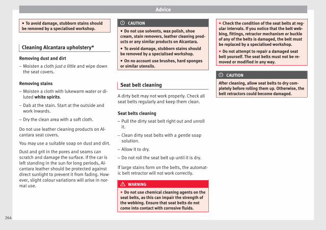
Advice
● To avoid damage, stubborn stains shouldbe removed by a specialised workshop.
Cleaning Alcantara upholstery*
Removing dust and dirt
– Moisten a cloth just a little and wipe downthe seat covers.
Removing stains
– Moisten a cloth with lukewarm water or di-luted white spirits.
– Dab at the stain. Start at the outside andwork inwards.
– Dry the clean area with a soft cloth.
Do not use leather cleaning products on Al-cantara seat covers.
You may use a suitable soap on dust and dirt.
Dust and grit in the pores and seams canscratch and damage the surface. If the car isleft standing in the sun for long periods, Al-cantara leather should be protected againstdirect sunlight to prevent it from fading. How-ever, slight colour variations will arise in nor-mal use.
CAUTION
● Do not use solvents, wax polish, shoecream, stain removers, leather cleaning prod-ucts or any similar products on Alcantara.
● To avoid damage, stubborn stains shouldbe removed by a specialised workshop.
● On no account use brushes, hard spongesor similar utensils.
Seat belt cleaning
A dirty belt may not work properly. Check allseat belts regularly and keep them clean.
Seat belts cleaning
– Pull the dirty seat belt right out and unrollit.
– Clean dirty seat belts with a gentle soapsolution.
– Allow it to dry.
– Do not roll the seat belt up until it is dry.
If large stains form on the belts, the automat-ic belt retractor will not work correctly.
WARNING
● Do not use chemical cleaning agents on theseat belts, as this can impair the strength ofthe webbing. Ensure that seat belts do notcome into contact with corrosive fluids.
● Check the condition of the seat belts at reg-ular intervals. If you notice that the belt web-bing, fittings, retractor mechanism or buckleof any of the belts is damaged, the belt mustbe replaced by a specialised workshop.
● Do not attempt to repair a damaged seatbelt yourself. The seat belts must not be re-moved or modified in any way.
CAUTION
After cleaning, allow seat belts to dry com-pletely before rolling them up. Otherwise, thebelt retractors could become damaged.
264
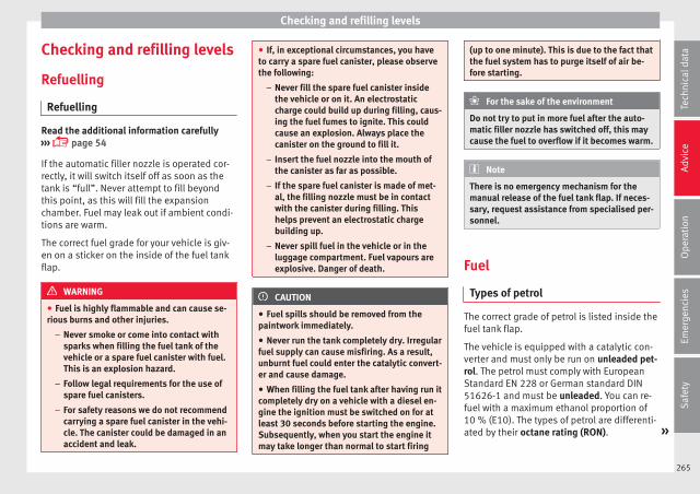
Checking and refilling levels
Checking and refilling levels
Refuelling
Refuelling
Read the additional information carefully››› page 54
If the automatic filler nozzle is operated cor-rectly, it will switch itself off as soon as thetank is “full”. Never attempt to fill beyondthis point, as this will fill the expansionchamber. Fuel may leak out if ambient condi-tions are warm.
The correct fuel grade for your vehicle is giv-en on a sticker on the inside of the fuel tankflap.
WARNING
● Fuel is highly flammable and can cause se-rious burns and other injuries.
– Never smoke or come into contact withsparks when filling the fuel tank of thevehicle or a spare fuel canister with fuel.This is an explosion hazard.
– Follow legal requirements for the use ofspare fuel canisters.
– For safety reasons we do not recommendcarrying a spare fuel canister in the vehi-cle. The canister could be damaged in anaccident and leak.
● If, in exceptional circumstances, you haveto carry a spare fuel canister, please observethe following:
– Never fill the spare fuel canister insidethe vehicle or on it. An electrostaticcharge could build up during filling, caus-ing the fuel fumes to ignite. This couldcause an explosion. Always place thecanister on the ground to fill it.
– Insert the fuel nozzle into the mouth ofthe canister as far as possible.
– If the spare fuel canister is made of met-al, the filling nozzle must be in contactwith the canister during filling. Thishelps prevent an electrostatic chargebuilding up.
– Never spill fuel in the vehicle or in theluggage compartment. Fuel vapours areexplosive. Danger of death.
CAUTION
● Fuel spills should be removed from thepaintwork immediately.
● Never run the tank completely dry. Irregularfuel supply can cause misfiring. As a result,unburnt fuel could enter the catalytic convert-er and cause damage.
● When filling the fuel tank after having run itcompletely dry on a vehicle with a diesel en-gine the ignition must be switched on for atleast 30 seconds before starting the engine.Subsequently, when you start the engine itmay take longer than normal to start firing
(up to one minute). This is due to the fact thatthe fuel system has to purge itself of air be-fore starting.
For the sake of the environment
Do not try to put in more fuel after the auto-matic filler nozzle has switched off, this maycause the fuel to overflow if it becomes warm.
Note
There is no emergency mechanism for themanual release of the fuel tank flap. If neces-sary, request assistance from specialised per-sonnel.
Fuel
Types of petrol
The correct grade of petrol is listed inside thefuel tank flap.
The vehicle is equipped with a catalytic con-verter and must only be run on unleaded pet-rol. The petrol must comply with EuropeanStandard EN 228 or German standard DIN51626-1 and must be unleaded. You can re-fuel with a maximum ethanol proportion of10 % (E10). The types of petrol are differenti-ated by their octane rating (RON). »
265
Tech
nica
l dat
aA
dvic
eO
pera
tion
Emer
genc
ies
Saf
ety

Advice
The following titles appear on the corre-sponding adhesive on the fuel tank flap:
Super unleaded 95 octane or normal 91 oc-tane unleaded petrol
We recommend you use super 95 octane pet-rol. If this is not available: normal 91 octanepetrol, with a slight decrease in power.
Super unleaded petrol with a minimum of 95octanes
You should use super petrol with a minimumof 95 octanes.
If super is not available, in an emergency youmay refuel with normal 91 octane petrol. Inthis case only use moderate engine speedsand a light throttle. Refuel with super as soonas possible.
Super unleaded 98 octane or super 95 oc-tane unleaded petrol
We recommend you use super plus 98 octanepetrol. If this is not available: super 95 oc-tane petrol, with a slight decrease in power.
If super is not available, in an emergency youmay refuel with normal 91 octane petrol. Inthis case only use moderate engine speedsand a light throttle. Refuel with super as soonas possible.
Petrol additives
The quality of the fuel influences the behav-iour, power and service life of the engine.This is why the petrol you use should carrysuitable additives already included by thepetrol industry, free of metals. These addi-tives will help to prevent corrosion, keep thefuel system clean and prevent deposits frombuilding up in the engine.
If good-quality petrol with metal-free addi-tives is not available or engine problemsarise, the necessary additives must be addedwhen refuelling ››› .
Not all petrol additives have been shown tobe effective. The use of unsuitable petrol ad-ditives may cause significant damage to theengine and the catalytic converter. Metal ad-ditives should never be used. Metal additivesmay also be contained in petrol additives forimproving anti-detonation ratings or octaneratings ››› .
SEAT recommends “genuine VolkswagenGroup Fuel Additives for petrol engines”.These additives can be bought at SEAT deal-ers, where information on how to use themcan also be obtained.
CAUTION
● Do not refuel if the filler indicates that thefuel contains metal. LRP (lead replacementpetrol) fuels contain high concentrations of
metal additives. Using them may damage theengine!
● Never refuel with fuels containing a largeproportion of ethanol (for example, E50, E85).This could damage the fuel system.
● Just filling one full tank of leaded fuel orfuel containing other metal additives wouldseriously impair the efficiency of the catalyticconverter.
● Only use fuel additives that have been ap-proved by SEAT. Octane boosting or anti-knock additives may contain metal additivesthat could seriously damage the engine orthe catalytic converter. These additives mustnot be used.
● High engine speed and full throttle candamage the engine when using petrol with anoctane rating lower than the correct grade forthe engine.
Note
● You may use petrol with a high octane num-ber than the one recommended for your en-gine.
● In those countries where unleaded petrol isnot available, you may refuel with a fuel witha low lead content.
Diesel fuel
Please note the information on the inside ofthe fuel tank flap.
266
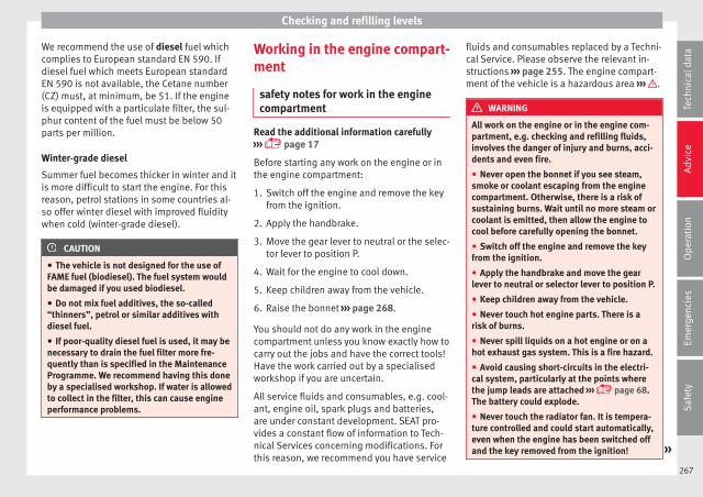
Checking and refilling levels
We recommend the use of diesel fuel whichcomplies to European standard EN 590. Ifdiesel fuel which meets European standardEN 590 is not available, the Cetane number(CZ) must, at minimum, be 51. If the engineis equipped with a particulate filter, the sul-phur content of the fuel must be below 50parts per million.
Winter-grade diesel
Summer fuel becomes thicker in winter and itis more difficult to start the engine. For thisreason, petrol stations in some countries al-so offer winter diesel with improved fluiditywhen cold (winter-grade diesel).
CAUTION
● The vehicle is not designed for the use ofFAME fuel (biodiesel). The fuel system wouldbe damaged if you used biodiesel.
● Do not mix fuel additives, the so-called“thinners”, petrol or similar additives withdiesel fuel.
● If poor-quality diesel fuel is used, it may benecessary to drain the fuel filter more fre-quently than is specified in the MaintenanceProgramme. We recommend having this doneby a specialised workshop. If water is allowedto collect in the filter, this can cause engineperformance problems.
Working in the engine compart-ment
safety notes for work in the enginecompartment
Read the additional information carefully››› page 17
Before starting any work on the engine or inthe engine compartment:
1. Switch off the engine and remove the keyfrom the ignition.
2. Apply the handbrake.
3. Move the gear lever to neutral or the selec-tor lever to position P.
4. Wait for the engine to cool down.
5. Keep children away from the vehicle.
6. Raise the bonnet ››› page 268.
You should not do any work in the enginecompartment unless you know exactly how tocarry out the jobs and have the correct tools!Have the work carried out by a specialisedworkshop if you are uncertain.
All service fluids and consumables, e.g. cool-ant, engine oil, spark plugs and batteries,are under constant development. SEAT pro-vides a constant flow of information to Tech-nical Services concerning modifications. Forthis reason, we recommend you have service
fluids and consumables replaced by a Techni-cal Service. Please observe the relevant in-structions ››› page 255. The engine compart-ment of the vehicle is a hazardous area ››› .
WARNING
All work on the engine or in the engine com-partment, e.g. checking and refilling fluids,involves the danger of injury and burns, acci-dents and even fire.
● Never open the bonnet if you see steam,smoke or coolant escaping from the enginecompartment. Otherwise, there is a risk ofsustaining burns. Wait until no more steam orcoolant is emitted, then allow the engine tocool before carefully opening the bonnet.
● Switch off the engine and remove the keyfrom the ignition.
● Apply the handbrake and move the gearlever to neutral or selector lever to position P.
● Keep children away from the vehicle.
● Never touch hot engine parts. There is arisk of burns.
● Never spill liquids on a hot engine or on ahot exhaust gas system. This is a fire hazard.
● Avoid causing short-circuits in the electri-cal system, particularly at the points wherethe jump leads are attached ››› page 68.The battery could explode.
● Never touch the radiator fan. It is tempera-ture controlled and could start automatically,even when the engine has been switched offand the key removed from the ignition! »
267
Tech
nica
l dat
aA
dvic
eO
pera
tion
Emer
genc
ies
Saf
ety
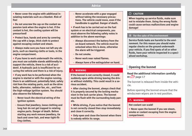
Advice
● Never cover the engine with additional in-sulating materials such as a blanket. Risk offire!
● Do not unscrew the cap on the coolant ex-pansion tank when the engine is hot. If thecoolant is hot, the cooling system will bepressurised!
● Protect face, hands and arms by coveringthe cap with a large, thick cloth to protectagainst escaping coolant and steam.
● Always make sure you have not left any ob-jects, such as cleaning cloths or tools, in theengine compartment.
● If you have to work underneath the vehicle,you must use suitable stands additionally tosupport the vehicle, there is a risk of acci-dent!. A hydraulic jack is insufficient for se-curing the vehicle and there is a risk of injury.
● If any work has to be performed when theengine is started or with the engine running,there is an additional, potentially fatal, safetyrisk from the rotating parts, such as the drivebelts, alternator, radiator fan, etc., and fromthe high-voltage ignition system. You shouldalso observe the following:
– Never touch the electrical wiring of theignition system.
– Ensure that jewellery, loose clothing andlong hair do not get trapped in rotatingengine parts. Danger of death. Beforestarting any work remove jewellery, tieback and cover hair, and wear tight-fit-ting clothes.
– Never accelerate with a gear engagedwithout taking the necessary precau-tions. The vehicle could move, even if thehandbrake is applied. Danger of death.
● If work has to be carried out on the fuelsystem or on electrical components, youmust observe the following safety notes inaddition to the above warnings:
– Always disconnect the battery from theon-board network. The vehicle must beunlocked when this is done, otherwisethe alarm will be triggered.
– Do not smoke.
– Never work near naked flames.
– Always have a fire extinguisher on hand.
WARNING
If the bonnet is not correctly closed, it couldsuddenly open while driving leaving the driv-er without visibility. This could result in a se-rious accident.
● After closing the bonnet, always check thatit is properly secured by the locking mecha-nism in the lock carrier piece. The bonnetmust be flush with the surrounding body pan-els.
● While driving, if you notice that the bonnetis not correctly closed then stop immediatelyand close it correctly.
● Only open and close the bonnet when thereis nobody within its range.
CAUTION
When topping up service fluids, make surenot to mistake them. Using the wrong fluidscould cause serious malfunctions and enginedamage!
For the sake of the environment
Service fluids leaks are harmful to the envi-ronment. For this reason you should makeregular checks on the ground underneathyour vehicle. If you find spots of oil or otherfluids, have your vehicle inspected in a speci-alised workshop.
Opening the bonnet
Read the additional information carefully››› page 17
The bonnet is released from inside the vehi-cle.
Before opening the bonnet ensure that thewindscreen wipers are in rest position.
WARNING
Hot coolant can scald!
● Never open the bonnet if you see steam,smoke or coolant escaping from the enginecompartment.
268
Checking and refilling levels
● Wait until no more steam, smoke or coolantis emitted from the bonnet, then carefullyopen the bonnet.
● When working in the engine compartment,always observe the safety warnings››› page 267.
Closing the bonnet
– Slightly lift the bonnet.
– Release the bonnet stay and replace it in itssupport.
– At a height of approximately 30 cm let it fallso it locks.
If the bonnet does not close, do not pressdownwards. Open it again and let it fall asmentioned above.
WARNING
If the bonnet is not closed properly, it couldopen while you are driving and completelyobscure your view of the road. Risk of acci-dent.
● After closing the bonnet, always check thatit is properly secured. The bonnet must beflush with the surrounding body panels.
● If you notice that the bonnet latch is not se-cured when the vehicle is moving, stop thevehicle immediately and close the bonnetproperly. Risk of accident.
269
Tech
nica
l dat
aA
dvic
eO
pera
tion
Emer
genc
ies
Saf
ety

Advice
Checking levels
Fig. 236 Diagram for the location of the various ele-ments.
From time to time, the levels of the differentfluids in the vehicle must be checked. Neverfill with incorrect fluids, otherwise seriousdamage to the engine may be caused.
Coolant expansion tank
Engine oil level dipstick
Engine oil filler cap
Brake fluid reservoir
Vehicle battery
Windscreen washer reservoir
The checking and refilling of service fluidsare carried out on the components men-
1
2
3
4
5
6
tioned above. These operations are descri-bed in ››› page 267.
Overview
You will find further explanations, instruc-tions and restrictions on the technical speci-fications as of ››› page 285.
Note
The layout of parts may vary depending onthe engine.
Engine oil
General notes
The engine comes with a special, multi-gradeoil that can be used all year round.
Because the use of high-quality oil is essen-tial for the correct operation of the engineand its long useful life, when topping up orchanging oil, use only those oils that complywith VW standards.
The specifications (VW standards) set out inthe following page should appear on the con-tainer of the service oil; when the containerdisplays the specific standards for petrol and
270

Checking and refilling levels
diesel engines together, it means that the oilcan be used for both types of engines.
We recommend that the oil change indicatedin the Maintenance Programme, be per-formed by a technical service or specialisedworkshop.
The correct oil specifications for your engineare listed in the ››› page 56.
Service intervals
Service intervals can be flexible (LongLifeservice) or fixed (dependent on time/dis-tance travelled).
If the PR code that appears on the back of theMaintenance Programme booklet is PR QI6,this means that your vehicle has the LongLifeservice program. If it lists the codes QI1, QI2,QI3, QI4 or QI7, the interval service is de-pendent on the time/distance travelled.
Flexible service intervals (LongLife serviceintervals*)
Special oils and processes have been devel-oped which, depending on the characteris-tics and individual driving profiles, enablethe extension of the oil change service (Long-Life service intervals).
Because this oil is essential for extending theservice intervals, it must only be used ob-serving the following indications:
● Avoid mixing it with oil for fixed service in-tervals.
● Only in exceptional circumstances, if theengine oil level is too low ››› page 272 andLongLife oil is not available, it is permitted totop up (once) with oil for fixed service inter-vals ››› page 56 (up to a maximum of 0.5litres).
Fixed service intervals*
If your vehicle does not have the “LongLifeservice interval” or it has been disabled (byrequest), you may use oils for fixed serviceintervals, which also appear in››› page 56. In this case, your vehiclemust be serviced after a fixed interval of 1year/15,000 km (10,000 miles)(whatevercomes first) ››› Booklet Maintenance Pro-gramme.
● In exceptional circumstances, if the engineoil level is too low ››› page 272 and you can-not obtain the oil specified for your vehicle,you can add a small quantity of oil conform-ing to the specification ACEA A2 or ACEA A3(petrol engines) or ACEA B3 or ACEA B4 (die-sel engines) (up to 0.5 l).
Vehicles with diesel particulate filter*
The Maintenance Programme states whetheryour vehicle is fitted with a diesel particulatefilter.
Only VW 507 00 engine oil, with reduced ashformation, may be used in diesel enginesequipped with particulate filter. Using othertypes of oil will cause a higher soot concen-tration and reduce the life of the DPF. There-fore:
● Avoid mixing this oil with other engine oils.
● Only in exceptional circumstances, if theengine oil level is too low ››› page 272 andyou cannot obtain the oil specified for yourvehicle, you can use a small quantity of oil(once) conforming to the VW 506 00,VW 506 01, VW 505 00, VW 505 01 orACEA B3/ACEA B4 specification. (up to 0.5 l).
Note
Before a long trip, we recommend finding anengine oil that conforms to the correspond-ing VW specifications and recommend keep-ing it in the vehicle. This way, the correct en-gine oil will always be available for a top-up ifneeded.
Warning lamp
If this warning lamp is red it indicatesthat the engine oil pressure is too low.
If this warning symbol starts to flash, and isaccompanied by three audible warnings,switch off the engine and check the oil level.If necessary, add more oil ››› page 272. »
271
Tech
nica
l dat
aA
dvic
eO
pera
tion
Emer
genc
ies
Saf
ety
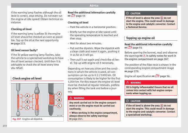
Advice
If the warning lamp flashes although the oillevel is correct, stop driving. Do not even runthe engine at idle speed! Obtain technical as-sistance.
Checking oil level
If the warning lamp is yellow the engineoil level should be checked as soon as possi-ble. Top up the oil at the next opportunity››› page 272.
Oil level sensor faulty*
If the yellow warning lamp flashes, takethe vehicle to a specialised workshop to havethe oil level sensor checked. Until then it isadvisable to check the oil level every timeyou refuel.
Check engine oil level
Fig. 237 Engine oil dipstick.
Read the additional information carefully››› page 55
Checking oil level
– Park the vehicle in a horizontal position.
– Briefly run the engine at idle speed untilthe operating temperature is reached andthen stop.
– Wait for about two minutes.
– Pull out the dipstick. Wipe the dipstick witha clean cloth and insert it again, pushing itin as far as it will go.
– Then pull it out again and check the oil lev-el. Top up with engine oil if necessary.
Depending on how you drive and the condi-tions in which the vehicle is used, oil con-sumption can be up to 0.5 l/1000 km. Oilconsumption is likely to be higher for the first5,000 km. For this reason the engine oil levelmust be checked at regular intervals, prefera-bly when filling the tank and before a jour-ney.
WARNING
Any work carried out in the engine compart-ment or on the engine must be carried outcautiously.
● When working in the engine compartment,always observe the safety warnings››› page 267.
CAUTION
If the oil level is above the area A do notstart the engine. This could result in damageto the engine and catalytic converter. Contacta Technical Service.
Topping up engine oil
Read the additional information carefully››› page 55
Before opening the bonnet, read and observethe warnings ››› in safety notes for work inthe engine compartment on page 267.
The position of the filler neck is shown in thecorresponding engine compartment image››› page 270.
Engine oil specification ››› page 56.
WARNING
Oil is highly inflammable! Ensure that no oilcomes into contact with hot engine compo-nents when topping up.
CAUTION
If the oil level is above the area A do notstart the engine. This could result in damageto the engine and catalytic converter. Contacta specialised workshop.
272
Checking and refilling levels
For the sake of the environment
The oil level must never be above area A .Otherwise oil can be drawn in through thecrankcase breather and escape into the at-mosphere via the exhaust system.
Changing engine oil
Read the additional information carefully››› page 55
The engine oil must be changed at the inter-vals given in the service schedule.
We recommend that you have the engine oilchanged by a Technical Service.
The oil change intervals are shown in theMaintenance Programme.
WARNING
Only change the engine oil yourself if youhave the specialist knowledge required!
● Before opening the bonnet, read and ob-serve the warnings ››› page 267, safety notesfor work in the engine compartment.
● Wait for the engine to cool down. Hot oilmay cause burn injuries.
● Wear eye protection to avoid injuries, suchas acid burns, caused by splashes of oil.
● When removing the oil drain plug with yourfingers, keep your arm horizontal to help pre-vent oil from running down your arm.
● Wash your skin thoroughly if it comes intocontact with engine oil.
● Engine oil is poisonous! Used engine oilmust be stored in a safe place out of thereach of children.
CAUTION
No additives should be used with engine oil.This could result in engine damage. Any dam-age caused by the use of such additiveswould not be covered by the factory warranty.
For the sake of the environment
● Because of disposal problems and the spe-cial tools and specialist knowledge required,we recommend that you have the engine oiland filter changed by a Technical Service.
● Never pour oil down drains or into theground.
● Use a suitable container when draining theused oil. It must be large enough to hold allthe engine oil.
Cooling system
Control lamp
There is a fault if:
● The lamp does not go out again after afew seconds.
● The lamp lights up or flashes while thevehicle is running, and three acoustic warn-ing signals are emitted ››› .
This means that either the coolant level is toolow or the coolant temperature is too high.
Coolant temperature too high
If the lamp lights up, stop the vehicle,turn off the engine and wait for it to cooldown. Check the coolant level.
If the coolant level is correct, the overheatingmay be caused by a malfunction of the radia-tor fan. Check the radiator fan fuse and haveit replaced if necessary ››› page 100.
If the control lamp lights up again after driv-ing on for a short distance, stop the vehicleand switch the engine off. Contact a Techni-cal Service or a specialised workshop.
Coolant level too low
If the lamp lights up, stop the vehicle,turn off the engine and wait for it to cooldown. First check the coolant level. If the lev-el of the coolant is below the “MIN” mark,top up with coolant liquid ››› .
WARNING
● If your vehicle is immobilised for technicalreasons, move it to a safe distance from traf-fic. Turn the engine off, turn the hazard lightson and place the warning triangle. »
273
Tech
nica
l dat
aA
dvic
eO
pera
tion
Emer
genc
ies
Saf
ety

Advice
● Never open the bonnet if you can see orhear steam or coolant escaping from the en-gine compartment. Risk of scalding. Wait un-til you can no longer see or hear escapingsteam or coolant.
● The engine compartment is a dangerousarea. Before carrying out any work in the en-gine compartment, switch off the engine andallow it to cool down. Always note the corre-sponding warnings ››› page 267.
Topping up coolant
Read the additional information carefully››› page 56
Top up coolant when the level is below theMIN (minimum) mark.
Checking coolant level
– Park the vehicle in a horizontal position.
– Switch the ignition off.
– Read off the coolant level on coolant ex-pansion tank. When the engine is cold, thecoolant level should be between the marks.When the engine is hot, it may be slightlyabove the upper mark.
Topping up coolant
– Wait for the engine to cool down.
– Cover the coolant expansion tank cap witha cloth and carefully unscrew it to the left››› .
– Top up the coolant only if there is still cool-ant in the expansion tank, otherwise youcould damage the engine. If there is nocoolant in the expansion tank, do not con-tinue driving. You should obtain professio-nal assistance ››› .
– If there is still some coolant in the expan-sion tank, top up to the upper mark.
– Top up with coolant until the level becomesstable.
– Screw the cap back on correctly.
Any loss of coolant fluid normally indicates aleak in the cooling system. Take the vehiclestraight to a specialised workshop to havethe cooling system examined. If there are noleaks in the engine cooling system, a loss ofcoolant can only occur if the coolant boilsand is forced out of the system as a result ofoverheating.
WARNING
● The cooling system is under pressure. Donot unscrew the cap on the coolant expan-sion tank when the engine is hot: risk ofburns!
● The antifreeze and coolant fluid can be ahealth hazard. Therefore, the antifreezeshould be stored in the original container in a
safe place out of reach of children. Failure tocomply could result in poisoning.
● If working inside the engine compartment,remember that, even when the ignition isswitched off, the radiator fan may start up au-tomatically, and therefore there is a risk of in-jury.
WARNING
If there is not enough anti-freeze in the cool-ant system, the engine may fail leading to se-rious damage.
● Please make sure that the percentage ofadditive is correct with respect to the lowestexpected ambient temperature in the zone inwhich the vehicle is to be used.
● When the outside temperature is very low,the coolant could freeze and the vehiclewould be immobilised. In this case, the heat-ing would not work either and inadequatelydressed passengers could die of cold.
CAUTION
Do not top up the expansion tank with cool-ant fluid if it is empty! Air could enter thecooling system. In this case, stop driving.Seek specialist assistance. Otherwise, thereis a risk of engine damage.
274
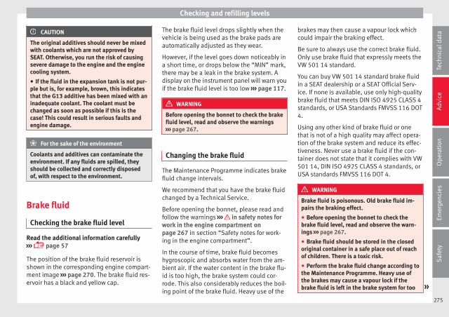
Checking and refilling levels
CAUTION
The original additives should never be mixedwith coolants which are not approved bySEAT. Otherwise, you run the risk of causingsevere damage to the engine and the enginecooling system.
● If the fluid in the expansion tank is not pur-ple but is, for example, brown, this indicatesthat the G13 additive has been mixed with aninadequate coolant. The coolant must bechanged as soon as possible if this is thecase! This could result in serious faults andengine damage.
For the sake of the environment
Coolants and additives can contaminate theenvironment. If any fluids are spilled, theyshould be collected and correctly disposedof, with respect to the environment.
Brake fluid
Checking the brake fluid level
Read the additional information carefully››› page 57
The position of the brake fluid reservoir isshown in the corresponding engine compart-ment image ››› page 270. The brake fluid res-ervoir has a black and yellow cap.
The brake fluid level drops slightly when thevehicle is being used as the brake pads areautomatically adjusted as they wear.
However, if the level goes down noticeably ina short time, or drops below the “MIN” mark,there may be a leak in the brake system. Adisplay on the instrument panel will warn youif the brake fluid level is too low ››› page 117.
WARNING
Before opening the bonnet to check the brakefluid level, read and observe the warnings››› page 267.
Changing the brake fluid
The Maintenance Programme indicates brakefluid change intervals.
We recommend that you have the brake fluidchanged by a Technical Service.
Before opening the bonnet, please read andfollow the warnings ››› in safety notes forwork in the engine compartment onpage 267 in section “Safety notes for work-ing in the engine compartment”.
In the course of time, brake fluid becomeshygroscopic and absorbs water from the am-bient air. If the water content in the brake flu-id is too high, the brake system could cor-rode. This also considerably reduces the boil-ing point of the brake fluid. Heavy use of the
brakes may then cause a vapour lock whichcould impair the braking effect.
Be sure to always use the correct brake fluid.Only use brake fluid that expressly meets theVW 501 14 standard.
You can buy VW 501 14 standard brake fluidin a SEAT dealership or a SEAT Official Serv-ice. If none is available, use only high-qualitybrake fluid that meets DIN ISO 4925 CLASS 4standards, or USA Standards FMVSS 116 DOT4.
Using any other kind of brake fluid or onethat is not of a high quality may affect opera-tion of the brake system and reduce its effec-tiveness. Never use a brake fluid if the con-tainer does not state that it complies with VW501 14, DIN ISO 4925 CLASS 4 standards, orUSA standards FMVSS 116 DOT 4.
WARNING
Brake fluid is poisonous. Old brake fluid im-pairs the braking effect.
● Before opening the bonnet to check thebrake fluid level, read and observe the warn-ings ››› page 267.
● Brake fluid should be stored in the closedoriginal container in a safe place out of reachof children. There is a toxic risk.
● Perform the brake fluid change according tothe Maintenance Programme. Heavy use ofthe brakes may cause a vapour lock if thebrake fluid is left in the brake system for too »
275
Tech
nica
l dat
aA
dvic
eO
pera
tion
Emer
genc
ies
Saf
ety
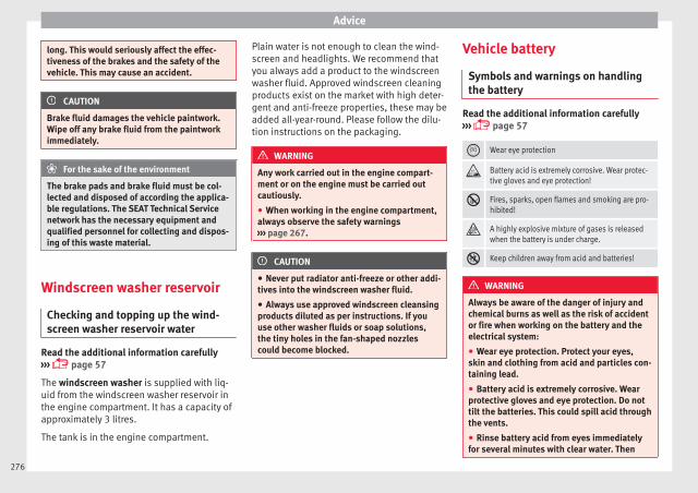
Advice
long. This would seriously affect the effec-tiveness of the brakes and the safety of thevehicle. This may cause an accident.
CAUTION
Brake fluid damages the vehicle paintwork.Wipe off any brake fluid from the paintworkimmediately.
For the sake of the environment
The brake pads and brake fluid must be col-lected and disposed of according the applica-ble regulations. The SEAT Technical Servicenetwork has the necessary equipment andqualified personnel for collecting and dispos-ing of this waste material.
Windscreen washer reservoir
Checking and topping up the wind-screen washer reservoir water
Read the additional information carefully››› page 57
The windscreen washer is supplied with liq-uid from the windscreen washer reservoir inthe engine compartment. It has a capacity ofapproximately 3 litres.
The tank is in the engine compartment.
Plain water is not enough to clean the wind-screen and headlights. We recommend thatyou always add a product to the windscreenwasher fluid. Approved windscreen cleaningproducts exist on the market with high deter-gent and anti-freeze properties, these may beadded all-year-round. Please follow the dilu-tion instructions on the packaging.
WARNING
Any work carried out in the engine compart-ment or on the engine must be carried outcautiously.
● When working in the engine compartment,always observe the safety warnings››› page 267.
CAUTION
● Never put radiator anti-freeze or other addi-tives into the windscreen washer fluid.
● Always use approved windscreen cleansingproducts diluted as per instructions. If youuse other washer fluids or soap solutions,the tiny holes in the fan-shaped nozzlescould become blocked.
Vehicle battery
Symbols and warnings on handlingthe battery
Read the additional information carefully››› page 57
Wear eye protection
Battery acid is extremely corrosive. Wear protec-tive gloves and eye protection!
Fires, sparks, open flames and smoking are pro-hibited!
A highly explosive mixture of gases is releasedwhen the battery is under charge.
Keep children away from acid and batteries!
WARNING
Always be aware of the danger of injury andchemical burns as well as the risk of accidentor fire when working on the battery and theelectrical system:
● Wear eye protection. Protect your eyes,skin and clothing from acid and particles con-taining lead.
● Battery acid is extremely corrosive. Wearprotective gloves and eye protection. Do nottilt the batteries. This could spill acid throughthe vents.
● Rinse battery acid from eyes immediatelyfor several minutes with clear water. Then
276
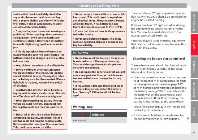
Checking and refilling levels
seek medical care immediately. Neutraliseany acid splashes on the skin or clothingwith a soapy solution, and rinse off with plen-ty of water. If acid is swallowed by mistake,consult a doctor immediately.
● Fires, sparks, open flames and smoking areprohibited. When handling cables and electri-cal equipment, avoid causing sparks andelectrostatic charge. Never short the batteryterminals. High-energy sparks can cause in-jury.
● A highly explosive mixture of gases is re-leased when the battery is under charge. Thebatteries should be charged in a well-ventila-ted room only.
● Keep children away from acid and batteries.
● Before working on the electrical system,you must switch off the engine, the ignitionand all electrical devices. The negative cableon the battery must be disconnected. When alight bulb is changed, you need only switchoff the light.
● Deactivate the anti-theft alarm by unlock-ing the vehicle before you disconnect the bat-tery! The alarm will otherwise be triggered.
● When disconnecting the battery from thevehicle on-board network, disconnect firstthe negative cable and then the positive ca-ble.
● Switch off all electrical devices before re-connecting the battery. Reconnect first thepositive cable and then the negative cable.Never reverse the polarity of the connections.This could cause an electrical fire.
● Never charge a frozen battery, or one whichhas thawed. This could result in explosionsand chemical burns. Always replace a batterywhich has frozen. A flat battery can alsofreeze at temperatures close to 0°C (+32°F).
● Ensure that the vent hose is always connec-ted to the battery.
● Never use a defective battery. This couldcause an explosion. Replace a damaged bat-tery immediately.
CAUTION
● Never disconnect the battery if the ignitionis switched on or if the engine is running.This could damage the electrical system orelectronic components.
● Do not expose the battery to direct sunlightover a long period of time, as the intense ul-traviolet radiation can damage the batteryhousing.
● If the vehicle is left standing in cold condi-tions for a long period, protect the batteryfrom “freezing”. If it freezes it will be dam-aged.
Warning lamp
It lights up
Alternator fault.
The control lamp lights up when the igni-tion is switched on. It should go out when theengine has started running.
If the control lamp lights up while driving,the alternator is no longer charging the bat-tery. You should immediately drive to thenearest specialised workshop.
You should avoid using electrical equipmentthat is not absolutely necessary because thiswill drain the battery.
Checking the battery electrolyte level
The electrolyte level should be checked regu-larly in high-mileage vehicles, in hot coun-tries and in older batteries.
– Open the bonnet and open the battery cov-er at the front ››› in safety notes for workin the engine compartment on page 267››› in Symbols and warnings on handlingthe battery on page 276. For vehicles withthe battery under the spare wheel, openthe rear lid and lift the floor covering. Thebattery is located next to the spare wheel.
– Check the colour display in the "magic eye"on the top of the battery.
– If there are air bubbles in the window, tapthe window gently until they disperse. »
277
Tech
nica
l dat
aA
dvic
eO
pera
tion
Emer
genc
ies
Saf
ety
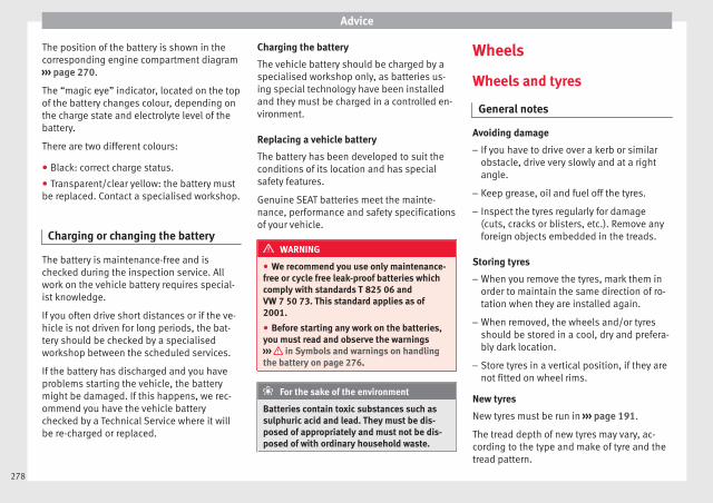
Advice
The position of the battery is shown in thecorresponding engine compartment diagram››› page 270.
The “magic eye” indicator, located on the topof the battery changes colour, depending onthe charge state and electrolyte level of thebattery.
There are two different colours:
● Black: correct charge status.
● Transparent/clear yellow: the battery mustbe replaced. Contact a specialised workshop.
Charging or changing the battery
The battery is maintenance-free and ischecked during the inspection service. Allwork on the vehicle battery requires special-ist knowledge.
If you often drive short distances or if the ve-hicle is not driven for long periods, the bat-tery should be checked by a specialisedworkshop between the scheduled services.
If the battery has discharged and you haveproblems starting the vehicle, the batterymight be damaged. If this happens, we rec-ommend you have the vehicle batterychecked by a Technical Service where it willbe re-charged or replaced.
Charging the battery
The vehicle battery should be charged by aspecialised workshop only, as batteries us-ing special technology have been installedand they must be charged in a controlled en-vironment.
Replacing a vehicle battery
The battery has been developed to suit theconditions of its location and has specialsafety features.
Genuine SEAT batteries meet the mainte-nance, performance and safety specificationsof your vehicle.
WARNING
● We recommend you use only maintenance-free or cycle free leak-proof batteries whichcomply with standards T 825 06 andVW 7 50 73. This standard applies as of2001.
● Before starting any work on the batteries,you must read and observe the warnings››› in Symbols and warnings on handlingthe battery on page 276.
For the sake of the environment
Batteries contain toxic substances such assulphuric acid and lead. They must be dis-posed of appropriately and must not be dis-posed of with ordinary household waste.
Wheels
Wheels and tyres
General notes
Avoiding damage
– If you have to drive over a kerb or similarobstacle, drive very slowly and at a rightangle.
– Keep grease, oil and fuel off the tyres.
– Inspect the tyres regularly for damage(cuts, cracks or blisters, etc.). Remove anyforeign objects embedded in the treads.
Storing tyres
– When you remove the tyres, mark them inorder to maintain the same direction of ro-tation when they are installed again.
– When removed, the wheels and/or tyresshould be stored in a cool, dry and prefera-bly dark location.
– Store tyres in a vertical position, if they arenot fitted on wheel rims.
New tyres
New tyres must be run in ››› page 191.
The tread depth of new tyres may vary, ac-cording to the type and make of tyre and thetread pattern.
278
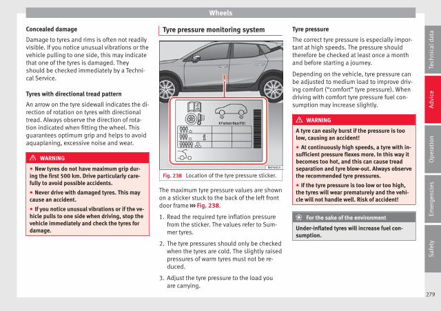
Wheels
Concealed damage
Damage to tyres and rims is often not readilyvisible. If you notice unusual vibrations or thevehicle pulling to one side, this may indicatethat one of the tyres is damaged. Theyshould be checked immediately by a Techni-cal Service.
Tyres with directional tread pattern
An arrow on the tyre sidewall indicates the di-rection of rotation on tyres with directionaltread. Always observe the direction of rota-tion indicated when fitting the wheel. Thisguarantees optimum grip and helps to avoidaquaplaning, excessive noise and wear.
WARNING
● New tyres do not have maximum grip dur-ing the first 500 km. Drive particularly care-fully to avoid possible accidents.
● Never drive with damaged tyres. This maycause an accident.
● If you notice unusual vibrations or if the ve-hicle pulls to one side when driving, stop thevehicle immediately and check the tyres fordamage.
Tyre pressure monitoring system
Fig. 238 Location of the tyre pressure sticker.
The maximum tyre pressure values are shownon a sticker stuck to the back of the left frontdoor frame ››› Fig. 238.
1. Read the required tyre inflation pressurefrom the sticker. The values refer to Sum-mer tyres.
2. The tyre pressures should only be checkedwhen the tyres are cold. The slightly raisedpressures of warm tyres must not be re-duced.
3. Adjust the tyre pressure to the load youare carrying.
Tyre pressure
The correct tyre pressure is especially impor-tant at high speeds. The pressure shouldtherefore be checked at least once a monthand before starting a journey.
Depending on the vehicle, tyre pressure canbe adjusted to medium load to improve driv-ing comfort (“comfort” tyre pressure). Whendriving with comfort tyre pressure fuel con-sumption may increase slightly.
WARNING
A tyre can easily burst if the pressure is toolow, causing an accident!
● At continuously high speeds, a tyre with in-sufficient pressure flexes more. In this way itbecomes too hot, and this can cause treadseparation and tyre blow-out. Always observethe recommended tyre pressures.
● If the tyre pressure is too low or too high,the tyres will wear prematurely and the vehi-cle will not handle well. Risk of accident!
For the sake of the environment
Under-inflated tyres will increase fuel con-sumption.
279
Tech
nica
l dat
aA
dvic
eO
pera
tion
Emer
genc
ies
Saf
ety

Advice
Tyre useful life
Fig. 239 Tyre tread wear indicators.
Fig. 240 Diagram for changing wheels.
The useful life of tyres is dependent on tyrepressure, driving style and fitting.
Wear indicators
The original tyres on your vehicle have1.6 mm high “tread wear indicators”››› Fig. 239, running across the tread. De-
pending on the make, there will be 6 to 8 ofthem evenly spaced around the tyre. Mark-ings on the tyre sidewall (for instance the let-ters “TWI” or other symbols) indicate the po-sitions of the tread wear indicators. The mini-mum tread depth required by law is 1.6 mm(measured in the tread grooves next to thetread wear indicators). Worn tyres must be re-placed. Different figures may apply in exportcountries ››› .
Tyre pressure
Incorrect tyre pressure causes prematurewear and could cause tyre blow-out. For thisreason, the tyre pressure should be checkedat least once per month ››› page 279.
Driving style
Fast cornering, heavy acceleration and hardbraking all increase tyre wear.
Changing wheels around
If the front tyres are worn considerably morethan the rear ones it is advisable to changethem around as shown ››› Fig. 240. The use-ful life of all the tyres will then be about thesame time.
Wheel balance
The wheels on new vehicles are balanced.However, various factors encountered in nor-mal driving can cause them to become unbal-anced, which results in steering vibration.
Unbalanced wheels should be rebalanced, asthey otherwise cause excessive wear onsteering, suspension and tyres. A wheel mustalso be rebalanced when a new tyre is fitted.
Incorrect wheel alignment
Incorrect running gear alignment causes ex-cessive tyre wear, impairing the safety of thevehicle. If tyres show excessive wear, youshould have the wheel alignment checked bya Technical Service.
WARNING
There is a serious danger of accidents if a tyrebursts during driving!
● The tyres must be replaced at the latestwhen the tread wear indicators are worn››› page 280. Failure to follow this instructioncould result in an accident. Worn tyres do notgrip well at high speeds on wet roads. Thereis also a greater risk of “aquaplaning”.
● At continuously high speeds, a tyre with in-sufficient pressure flexes more. This causes itto overheat. This can cause tread separationand tyre blow-out. Risk of accident. Alwaysobserve the recommended tyre pressures.
● If tyres show excessive wear, you shouldhave the running gear checked by a TechnicalService.
● Keep chemicals such as oil, fuel and brakefluid away from tyres.
● Damaged wheels and tyres must be re-placed immediately!
280
Wheels
For the sake of the environment
Under-inflated tyres will increase fuel con-sumption.
New tyres and wheels
New tyres and wheels have to be run in.
The tyres and wheel rims are an essentialpart of the vehicle's design. Those approvedby SEAT are specially matched to the charac-teristics of the vehicle and make a major con-tribution to good road-holding and safe han-dling ››› .
Tyres should be replaced at least in pairs andnot individually (i.e. both front tyres or bothrear tyres together). A knowledge of tyre des-ignations makes it easier to choose the cor-rect tyres. Radial tyres have the tyre designa-tions marked on the sidewall, for example:
195/55 R16 91VThis contains the following information:
Tyre width in mm
Height/width ratio in %
Tyre construction: Radial
Rim diameter in inches
Load rating code
Speed rating
195
55
R
16
91
V
The tyres could also have the following infor-mation:
● A direction of rotation symbol
● “Reinforced” denotes heavy-duty tyres.
The manufacturing date is also indicated onthe tyre sidewall (possibly only on the innerside of the wheel).
“DOT ... 1116 ...” means, for example, thatthe tyre was produced in the 11th week of2016.
We recommend that work on tyres andwheels be carried out by a Technical Service.They are familiar with the procedure andhave the necessary special tools and spareparts as well as the proper facilities for dis-posing of the old tyres.
Any technical service has full information onthe technical requirements when installing orchanging tyres, wheels or wheel trims.
WARNING
● We recommend that you use only wheelsand tyres which have been approved by SEATfor your model. Failure to do so could impairvehicle handling. Risk of accident.
● Avoid running the vehicle on tyres that aremore than 6 years old. If you have no alterna-tive, you should drive slowly and with extracare at all times.
● Never use old tyres or those with an un-known “history of use”.
● If wheel trims are retrofitted, you must en-sure that the flow of air to the brakes is notrestricted. This could cause the brake systemto overheat.
● All four wheels must be fitted with radialtyres of the same type, size (rolling circumfer-ence) and the same tread pattern.
For the sake of the environment
Old tyres must be disposed of according tothe laws in the country concerned.
Note
● A SEAT Service Centre should be consultedto find out whether wheels or tyres of differ-ent sizes to those originally fitted by SEATcan be fitted, and to find out about the com-binations allowed between the front axle(axle 1) and the rear axle (axle 2).
● For technical reasons, it is not generallypossible to use the wheels from other vehi-cles. This can also apply to wheels of thesame model. The use of wheels or tyreswhich have not been approved by SEAT foruse with your model may invalidate the vehi-cle's type approval for use on public roads.
● If the spare tyre is not the same as thetyres that are mounted on the vehicle (e.g.winter tyres) you should only use the sparetyre for a short period of time and drive with »
281
Tech
nica
l dat
aA
dvic
eO
pera
tion
Emer
genc
ies
Saf
ety

Advice
extra care. Refit the normal road wheel assoon as possible.
Wheel bolts
The design of wheel bolts is matched to therims. If different wheel rims are fitted, thecorrect wheel bolts with the right length andcorrectly shaped bolt heads must be used.This ensures that wheels are fitted securelyand that the brake system functions correctly.
In certain circumstances, you should not usewheel bolts from a different vehicle, even if itis the same model ››› page 255.
WARNING
If the wheel bolts are not tightened correctly,the wheel could become loose while driving.Risk of accident.
● The wheel bolts must be clean and turneasily. Never apply grease or oil to them.
● Use only wheel bolts which belong to thewheel.
● If the prescribed torque of the wheel boltsis too low, they could loosen whilst the vehi-cle is in motion. Risk of accident! If the tight-ening torque is too high, the wheel bolts andthreads can be damaged.
CAUTION
The prescribed tightening torque for wheelbolts for steel and alloy wheels is 120 Nm.
Tyre monitoring indicator*
Fig. 241 Centre console: tyre monitoring sys-tem button.
The tyre monitoring system compares wheelrevolutions alongside the wheel diameter ofeach wheel, with help from the ESC. If the di-ameter of a wheel changes, the tyre monitor-ing indicator lights up . The wheel diame-ter changes when:
● Tyre pressure is insufficient.
● The tyre structure is damaged.
● The vehicle is unbalanced because of aload.
● The wheels of one axle are under morepressure (for example, driving with a trailer oron steep slopes).
● The vehicle is fitted with snow chains.
● The temporary spare wheel is fitted.
● The wheel on one axle is changed.
Tyre pressure adjustment
After modifying tyre pressure or changing anywheels, the new tyre pressure must be storedin the Easy Connect system with the but-ton and the SETTINGS function button››› page 33.
You can also press and hold down the››› Fig. 241 button with the ignition on, untilan acoustic signal is heard.
If the wheels are under excessive load (for ex-ample, driving with a trailer or heavy load),the tyre pressure must be increased to therecommended value for a full load (see thesticker on the back of the left front doorframe). If the tyre monitor system button ispressed down, the new tyre pressures areconfirmed.
The tyre pressure control lamp lights up
If the tyre pressure of a wheel is much lowerthan the value set by the driver, then the tyrepressure control lamp ››› will light up.
282
Wheels
WARNING
● When the tyre pressure control lamp lightsup, reduce speed immediately and avoid anysudden turning or braking manoeuvre. Stopwhen possible, and check the tyre pressureand status.
● The driver is responsible for maintainingcorrect tyre pressures. For this reason, tyrepressure must be regularly checked.
● Under certain circumstances (e.g. whendriving in a sporty manner, in winter condi-tions or on a dirt track) the tyre control lampmay light up belatedly or may function incor-rectly.
Note
If the battery is disconnected, the yellowwarning lamp lights up after turning theignition on. This should turn off after a briefjourney.
Spare wheel (temporary sparewheel)*
Location and use of the temporaryspare wheel
The temporary spare wheel is stored underthe floor panel in the luggage compartmentand is attached by a thumbnut.
How to use the temporary spare wheel
If you ever have a punctured tyre or loss ofpressure, the temporary spare wheel is onlyintended for temporary use until you reach aworkshop. Change it for a duty wheel as soonas possible.
Please note the following restrictions whenusing the temporary spare wheel. This tem-porary spare wheel has been specially de-signed for your vehicle, thus, it cannot bechanged with the temporary spare wheelfrom another vehicle.
No other type of tyre (normal summer or win-ter tyre) may be fitted on the compact tempo-rary spare wheel rim.
Snow chains
For technical reasons, snow chains must notbe used on the temporary spare wheel.
If you have a puncture on one of the frontwheels when using snow chains, fit the tem-porary spare wheel in place of one of the rearwheels. Fit the snow chains on the rear wheelthat you have removed and replace the punc-tured front wheel with this wheel.
Getting the spare wheel out of vehicles withthe Beats Audio® sound system (6 speakerswith 1 subwoofer)*
● Disassemble the subwoofer's floor panel(carpet) as follows:
● Pull the carpet upwards to remove it.
● Disconnect the subwoofer's speaker cable.
● Turn the securing wheel anti-clockwise.
● Remove the subwoofer speaker and thespare wheel.
● When replacing the spare wheel, place thesubwoofer speaker in the direction indicatedby the arrow and with the word “FRONT” fac-ing forward.
● Reconnect the speaker cable and firmly ro-tate the securing wheel clockwise so that thesubwoofer system and wheel are firmly inplace.
WARNING
● After fitting the temporary spare wheel,check the tyre pressures as soon as possible.Failure to do so may cause an accident. Thetyre pressure is listed on the back of the leftfront door frame.
● Do not drive at over 80 km/h (50 mph)when the temporary spare wheel is fitted onthe vehicle: risk of accident!
● Avoid heavy acceleration, hard braking andfast cornering: risk of accident!
● Never use more than one temporary sparewheel at the same time, risk of accident.
● No other type of tyre (normal summer orwinter tyre) may be fitted on the compacttemporary spare wheel rim.
283
Tech
nica
l dat
aA
dvic
eO
pera
tion
Emer
genc
ies
Saf
ety
Advice
Winter service
Winter tyres
In winter conditions winter tyres will consid-erably improve the vehicle's handling. Thedesign of summer tyres (width, rubber com-pound, tread pattern) gives less grip on iceand snow.
Winter tyres must be inflated to a pressure of0.2 bar (2.9 psi/20 kPa) higher than the pres-sures specified for summer tyres (see thesticker on the back of the left front doorframe).
Winter tyres must be fitted on all four wheels.
Information on permitted winter tyre sizescan be found in the vehicle's registrationdocumentation. Use only radial winter tyres.All tyre sizes listed in the vehicle documenta-tion also apply to winter tyres.
Winter tyres lose their effectiveness when thetread is worn down to a depth of 4 mm.
The speed rating code ››› page 281, Newtyres and wheels determines the followingspeed limits for winter tyres: ›››
max. 160 km/h (99 mph)
max. 180 km/h (112 mph)
max. 190 km/h (118 mph)
max. 210 km/h (130 mph)
Q
S
T
H
In some countries, vehicles which can exceedthe speed rating of the fitted tyre must havean appropriate sticker in the driver's field ofview. These stickers are available from yourtechnical service. The legal requirements ofeach country must be followed.
Do not have winter tyres fitted for unnecessa-rily long periods. Vehicles with summer tyreshandle better when the roads are free ofsnow and ice.
If you have a flat tyre, please refer to thenotes on the spare wheel ››› page 281, Newtyres and wheels.
WARNING
The maximum speed for the winter tyres mustnot be exceeded. Otherwise, this could leadto damage and risk of accident.
For the sake of the environment
Fit your summer tyres again as soon as possi-ble. They are quieter, do not wear so quicklyand reduce fuel consumption.
284

Technical specifications
Technical data
Technical specifications
Important information
Important
The information in the vehicle documentationalways takes precedence over the informa-tion in this Instruction Manual.
All technical specifications provided in thisdocumentation are valid for the standardmodel in Spain. The vehicle data card inclu-ded in the Maintenance Programme or thevehicle registration documents shows whichengine is installed in the vehicle.
The figures may be different dependingwhether additional equipment is fitted, fordifferent models, for special vehicles and forother countries.
Abbreviations used in the technical specifi-cations section
kW Kilowatt, engine power measurement.
PSPferdestärke (horsepower), formerlyused to denote engine power.
rpm Revolutions per minute - engine speed.
Nm Newton metres, unit of engine torque.
CZCetane number, indication of the dieselcombustion power.
RONResearch octane number, indication ofthe knock resistance of petrol.
Vehicle identification data
Fig. 242 Vehicle data sticker (luggage com-partment).
Fig. 243 Chassis number.
Chassis number
The VIN is located in the Easy Connect, on thevehicle data sticker and under the wind-screen, on the driver side ››› Fig. 243. Addi-tionally, the chassis number is located in theengine compartment, on the right-hand side.The number is engraved on the top side rail,and is partially covered.
VIN in the Easy Connect
● Select: button > SETTINGS functionbutton > Service > Chassis number.
Identification plate
The identification plate is located on the rearpillar of the right-hand front door. Vehiclesfor certain export countries do not have anidentification plate. »
285
Tech
nica
l dat
aA
dvic
eO
pera
tion
Emer
genc
ies
Saf
ety
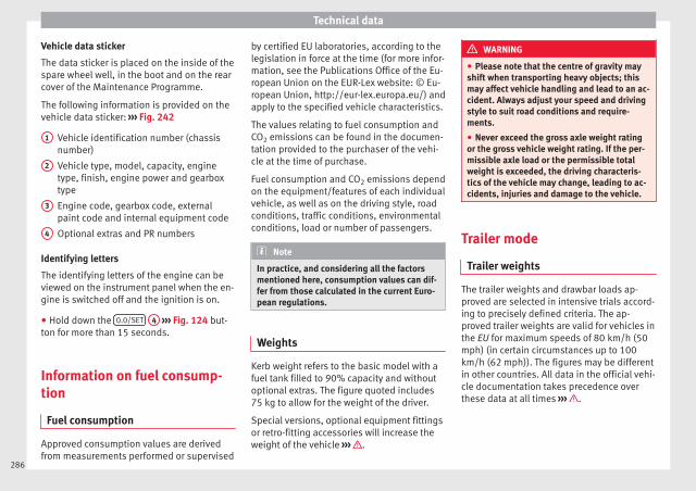
Technical data
Vehicle data sticker
The data sticker is placed on the inside of thespare wheel well, in the boot and on the rearcover of the Maintenance Programme.
The following information is provided on thevehicle data sticker: ››› Fig. 242
Vehicle identification number (chassisnumber)
Vehicle type, model, capacity, enginetype, finish, engine power and gearboxtype
Engine code, gearbox code, externalpaint code and internal equipment code
Optional extras and PR numbers
Identifying letters
The identifying letters of the engine can beviewed on the instrument panel when the en-gine is switched off and the ignition is on.
● Hold down the 0.0/SET 4 ››› Fig. 124 but-ton for more than 15 seconds.
Information on fuel consump-tion
Fuel consumption
Approved consumption values are derivedfrom measurements performed or supervised
1
2
3
4
by certified EU laboratories, according to thelegislation in force at the time (for more infor-mation, see the Publications Office of the Eu-ropean Union on the EUR-Lex website: © Eu-ropean Union, http://eur-lex.europa.eu/) andapply to the specified vehicle characteristics.
The values relating to fuel consumption andCO2 emissions can be found in the documen-tation provided to the purchaser of the vehi-cle at the time of purchase.
Fuel consumption and CO2 emissions dependon the equipment/features of each individualvehicle, as well as on the driving style, roadconditions, traffic conditions, environmentalconditions, load or number of passengers.
Note
In practice, and considering all the factorsmentioned here, consumption values can dif-fer from those calculated in the current Euro-pean regulations.
Weights
Kerb weight refers to the basic model with afuel tank filled to 90% capacity and withoutoptional extras. The figure quoted includes75 kg to allow for the weight of the driver.
Special versions, optional equipment fittingsor retro-fitting accessories will increase theweight of the vehicle ››› .
WARNING
● Please note that the centre of gravity mayshift when transporting heavy objects; thismay affect vehicle handling and lead to an ac-cident. Always adjust your speed and drivingstyle to suit road conditions and require-ments.
● Never exceed the gross axle weight ratingor the gross vehicle weight rating. If the per-missible axle load or the permissible totalweight is exceeded, the driving characteris-tics of the vehicle may change, leading to ac-cidents, injuries and damage to the vehicle.
Trailer mode
Trailer weights
The trailer weights and drawbar loads ap-proved are selected in intensive trials accord-ing to precisely defined criteria. The ap-proved trailer weights are valid for vehicles inthe EU for maximum speeds of 80 km/h (50mph) (in certain circumstances up to 100km/h (62 mph)). The figures may be differentin other countries. All data in the official vehi-cle documentation takes precedence overthese data at all times ››› .
286
Technical specifications
Drawbar loads
The maximum permitted drawbar load on theball joint of the towing bracket must not ex-ceed 75 kg.
In the interest of road safety, we recommendthat you always tow approaching the maxi-mum drawbar load. The response of the trail-er on the road will be poor, if the drawbarload is too small.
If the maximum permissible drawbar loadcannot be met (e.g. with small, empty andlight-weight single axle trailers or tandemaxle trailers with a wheelbase of less than 1metre), a minimum of 4% of the actual trailerweight is legally required for the drawbarload.
WARNING
● For safety reasons, you should not drive atspeeds above 80 km/h (50 mph) when towinga trailer. This also applies in countries wherehigher speeds are permitted.
● Never exceed the maximum trailer weightsor the drawbar load. If the permissible axleload or the permissible total weight is excee-ded, the driving characteristics of the vehiclemay change, leading to accidents, injuriesand damage to the vehicle.
Wheels
Tyre pressure and wheel bolts
Tyre pressures
The sticker with the tyre pressure values canbe found on the back of the left front doorframe. The tyre pressure values given thereare for cold tyres. Do not reduce the slightlyraised pressures of warm tyres ››› .
The pressure for winter tyres is 0.2 bar higherthan that of summer tyres (2.9 psi / 20 kPa).
Wheel bolts
After the wheels have been changed, thetightening torque of the wheel bolts shouldbe checked as soon as possible with a torquewrench ››› . The tightening torque for steeland alloy wheels is 120 Nm.
WARNING
● Check the tyre pressure at least once permonth. Checking the tyre pressure is very im-portant. If the tyre pressure is too high or toolow, there is an increased danger of accidents- particularly at high speeds.
● If the tightening torque of the wheel boltsis too low, they could loosen while the vehi-cle is in motion. Risk of accident! If the tight-ening torque is too high, the wheel bolts andthreads can be damaged.
Note
We recommend that you ask your TechnicalService for information about appropriatewheel, tyre and snow chain size.
287
Tech
nica
l dat
aA
dvic
eO
pera
tion
Emer
genc
ies
Saf
ety

Technical data
Engine data
Petrol engine 1.0 TSI 70 kW (95 PS)
Power output in kW (PS) at rpm Maximum torque (Nm at rpm) No. of cylinders/displacement (cm3) Fuel
70 (95)/5,000-5,500 175/2,000-3,500 3/999 Super 95 RON/Normal 91 RONa)
a) Slight power loss.
Outputs and weights ARONA
Top speed (km/h) a)
Acceleration from 0-80 km/h (seconds) a)
Acceleration from 0-100 km/h (seconds) a)
Maximum authorised weight (kg) a)
Weight in running order (with driver) (kg) a)
Maximum authorised weight on front axle (kg) a)
Maximum authorised weight on rear axle (kg) a)
Permitted roof load (kg) a)
Maximum trailer weight without brakes (kg) a)
Weight of trailer with brakes, gradients up to 8% (kg) a)
Weight of trailer with brakes, gradients up to 12% (kg) a)
a) Data not available as this edition goes to print.
288
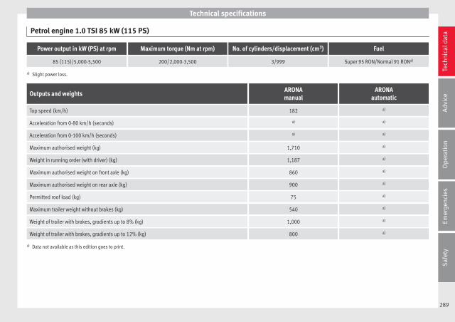
Technical specifications
Petrol engine 1.0 TSI 85 kW (115 PS)
Power output in kW (PS) at rpm Maximum torque (Nm at rpm) No. of cylinders/displacement (cm3) Fuel
85 (115)/5,000-5,500 200/2,000-3,500 3/999 Super 95 RON/Normal 91 RONa)
a) Slight power loss.
Outputs and weightsARONAmanual
ARONAautomatic
Top speed (km/h) 182 a)
Acceleration from 0-80 km/h (seconds) a) a)
Acceleration from 0-100 km/h (seconds) a) a)
Maximum authorised weight (kg) 1,710 a)
Weight in running order (with driver) (kg) 1,187 a)
Maximum authorised weight on front axle (kg) 860 a)
Maximum authorised weight on rear axle (kg) 900 a)
Permitted roof load (kg) 75 a)
Maximum trailer weight without brakes (kg) 540 a)
Weight of trailer with brakes, gradients up to 8% (kg) 1,000 a)
Weight of trailer with brakes, gradients up to 12% (kg) 800 a)
a) Data not available as this edition goes to print.
289
Tech
nica
l dat
aA
dvic
eO
pera
tion
Emer
genc
ies
Saf
ety
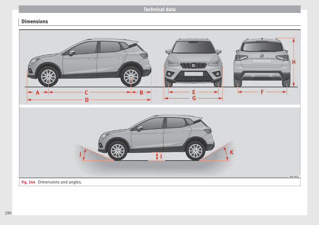
Technical data
Dimensions
Fig. 244 Dimensions and angles.
290

Technical specifications
››› Fig. 244 CROSSOVER
A Front projection (mm) 803
B Rear projection (mm) 769
C Wheelbase (mm) 2,566
D Length (mm) 4,138
E Fronta) track (mm) 1,503
F Backa) track (mm) 1,486
G Width (mm) 1,780
H Height at kerb weight (mm) 1,552b)
I Ground clearance between the axles (mm) 190
J Front projection angle limited by the bumper maximum 20.1°
K Rear projection angle limited by the bumper maximum 29.5°
Turning radius (m) 11.0
a) This data will change depending on the type of wheel rim.b) Dimension to the roof bars.
291
Tech
nica
l dat
aA
dvic
eO
pera
tion
Emer
genc
ies
Saf
ety

Index
Index
AABS . . . . . . . . . . . . . . . . . . . . . . . . . . . . . . . . . . . . 180
control lamp . . . . . . . . . . . . . . . . . . . . . . . . . . . 181ACC . . . . . . . . . . . . . . . . . . . . . . . . . . . . . . . . . . . . 209
radar sensor . . . . . . . . . . . . . . . . . . . . . . . . . . . 212Accessories . . . . . . . . . . . . . . . . . . . . . . . . . . . . . . 255Adaptive Cruise Control . . . . . . . . . . . . . . . . . . . . 209
deactivating temporarily . . . . . . . . . . . . . . . . . 216function for preventing overtaking in an inside
lane . . . . . . . . . . . . . . . . . . . . . . . . . . . . . . . . 216indications on the display . . . . . . . . . . . . . . . . 211malfunction . . . . . . . . . . . . . . . . . . . . . . . . . . . . 211operating . . . . . . . . . . . . . . . . . . . . . . . . . . . . . . 213radar sensor . . . . . . . . . . . . . . . . . . . . . . . . . . . 212special driving situations . . . . . . . . . . . . . . . . . 217warning and control lamp . . . . . . . . . . . . . . . . 211
Additional electrical appliances (efficiency pro-gramme) . . . . . . . . . . . . . . . . . . . . . . . . . . . . . . . 40
Adjustingfront head restraints . . . . . . . . . . . . . . . . . 75, 146lights . . . . . . . . . . . . . . . . . . . . . . . . . . . . . . . . . 141rear head restraints . . . . . . . . . . . . . . . . . 75, 147
Adjusting the head restraintsfront head restraints . . . . . . . . . . . . . . . . . . . . . 146rear head restraints . . . . . . . . . . . . . . . . . . . . . . 75
Adjusting the seatadjusting the lumbar support . . . . . . . . . . . . . 146
AdjustmentCAR menu . . . . . . . . . . . . . . . . . . . . . . . . . . . . . 118seats . . . . . . . . . . . . . . . . . . . . . . . . . . . . . . . . . . 72
Airbag covers . . . . . . . . . . . . . . . . . . . . . . . . . . . . . 21Airbags . . . . . . . . . . . . . . . . . . . . . . . . . . . . . . . . . . 82
description . . . . . . . . . . . . . . . . . . . . . . . . . . . . . 83
Airbag system . . . . . . . . . . . . . . . . . . . . . . . . . . 20, 82activation . . . . . . . . . . . . . . . . . . . . . . . . . . . . . . 83control lamp . . . . . . . . . . . . . . . . . . . . . . . . . . . . 84deactivation of front airbag . . . . . . . . . . . . . . . . 86description . . . . . . . . . . . . . . . . . . . . . . . . . . . . . 83front airbags . . . . . . . . . . . . . . . . . . . . . . . . . 21, 84functioning . . . . . . . . . . . . . . . . . . . . . . . . . . . . . 83head-protection airbags . . . . . . . . . . . . . . . . . . 22side airbags . . . . . . . . . . . . . . . . . . . . . . . . . . . . 22
Air conditioning . . . . . . . . . . . . . . . . . . . . . . . . . . . 48Climatronic . . . . . . . . . . . . . . . . . . . . . . . . . . . . 165controls . . . . . . . . . . . . . . . . . . . . . . . . . . . . . . . 163general notes . . . . . . . . . . . . . . . . . . . . . . . . . . 158manual air conditioning . . . . . . . . . . . . . . . . . . . 51
Air outlets . . . . . . . . . . . . . . . . . . . . . . . . . . . . . . . 159Air recirculation
air conditioning . . . . . . . . . . . . . . . . . . . . . . . . 160Alarm system . . . . . . . . . . . . . . . . . . . . . . . . . . . . 132
switching off . . . . . . . . . . . . . . . . . . . . . . . . . . . 133Alcantara: cleaning . . . . . . . . . . . . . . . . . . . . . . . 264Alloy wheel rims . . . . . . . . . . . . . . . . . . . . . . . . . . 261Alternator
warning lamp . . . . . . . . . . . . . . . . . . . . . . . . . . 277Ambient lighting . . . . . . . . . . . . . . . . . . . . . . . . . 142Anchoring
the front tow line. . . . . . . . . . . . . . . . . . . . . . . . . 98Anti-freeze . . . . . . . . . . . . . . . . . . . . . . . . . . . . . . . 56Anti-lock brake system . . . . . . . . . . . . 177, 179, 180
control lamp . . . . . . . . . . . . . . . . . . . . . . . . . . . 181Anti-puncture . . . . . . . . . . . . . . . . . . . . . . . . . . 60, 94Anti-puncture kit . . . . . . . . . . . . . . . . . . . . . . . . 60, 94
check after 10 minutes . . . . . . . . . . . . . . . . . . . . 95Anti-theft alarm system . . . . . . . . . . . . . . . . 15, 132
switching off . . . . . . . . . . . . . . . . . . . . . . . . . . . 133trailer . . . . . . . . . . . . . . . . . . . . . . . . . . . . . . . . . 253vehicle interior monitoring and anti-tow sys-
tem . . . . . . . . . . . . . . . . . . . . . . . . . . . . . . . . . 134Anti-tow protection . . . . . . . . . . . . . . . . . . . . . . . 134
Aquaplaning . . . . . . . . . . . . . . . . . . . . . . . . . . . . . 280Ashtray . . . . . . . . . . . . . . . . . . . . . . . . . . . . . . . . . 151Aspects to note before setting off . . . . . . . . . . . . . 71ASR . . . . . . . . . . . . . . . . . . . . . . . . . . . . . . . . . . . . 178
control lamp . . . . . . . . . . . . . . . . . . . . . . . . . . . 178Assistance Systems
ACC . . . . . . . . . . . . . . . . . . . . . . . . . . . . . . . . . . 209adaptive cruise control . . . . . . . . . . . . . . . . . . . 209blind spot detector (BSD) with parking assis-
tance (RCTA) . . . . . . . . . . . . . . . . . . . . . . . . . 220cruise control system . . . . . . . . . . . . . . . . . . . . 198fatigue detection . . . . . . . . . . . . . . . . . . . . . . . 227Front Assist . . . . . . . . . . . . . . . . . . . . . . . . . . . . 203Park Assist . . . . . . . . . . . . . . . . . . . . . . . . . . . . 228parking aid . . . . . . . . . . . . . . . . . . . . . . . 236, 237parking assistance (RCTA) . . . . . . . . . . . . . . . . 220pedestrian monitoring system . . . . . . . . . . . . . 208speed limiter . . . . . . . . . . . . . . . . . . . . . . . . . . . 200
Assisted starting . . . . . . . . . . . . . . . . . . . . . . . . . . 67Audible warning signal
seat belt not fastened . . . . . . . . . . . . . . . . . . . . 77warning and control lamps . . . . . . . . . . . . . . . 117
Automatic car wash tunnel . . . . . . . . . . . . . . . . . 257Automatic gearbox . . . . . . . . . . . . . . . . . . . . . . . . 183
backup programme . . . . . . . . . . . . . . . . . . . . . 189downhill speed control . . . . . . . . . . . . . . . . . . 188driving tips . . . . . . . . . . . . . . . . . . . . . . . . . . . . 186kick-down feature . . . . . . . . . . . . . . . . . . . . . . . 187launch control programme . . . . . . . . . . . . . . . . 187manual release of selector lever . . . . . . . . . . . . 48selector lever lock . . . . . . . . . . . . . . . . . . . . . . . 184selector lever positions . . . . . . . . . . . . . . . . . . 183steering wheel with gearshift paddles . . . . . . 185tiptronic . . . . . . . . . . . . . . . . . . . . . . . . . . 183, 185
Automatic lighting . . . . . . . . . . . . . . . . . . . . . . . . 138AUX-IN . . . . . . . . . . . . . . . . . . . . . . . . . . . . . . . . . . 123
293

Index
BBack seat
folding down and raising the back seat back-rest . . . . . . . . . . . . . . . . . . . . . . . . . . . . . . . . . 149
Battery . . . . . . . . . . . . . . . . . . . . . . . . . . . . . . . . . . 125Before setting off . . . . . . . . . . . . . . . . . . . . . . . . . . 71Belt pretensioners . . . . . . . . . . . . . . . . . . . . . . . . . 81Biodiesel . . . . . . . . . . . . . . . . . . . . . . . . . . . . . . . . 266Blind spot detector (BSD) . . . . . . . . . . . . . . . . . . 220
control lamps . . . . . . . . . . . . . . . . . . . . . . . . . . 220driving situations . . . . . . . . . . . . . . . . . . . . . . . 223indication in the external rear view mirror . . . 221malfunction . . . . . . . . . . . . . . . . . . . . . . . . . . . . 220operating . . . . . . . . . . . . . . . . . . . . . . . . . . . . . . 221towing . . . . . . . . . . . . . . . . . . . . . . . . . . . . . . . . 225
Bonnet . . . . . . . . . . . . . . . . . . . . . . . . . 17, 267, 270closing . . . . . . . . . . . . . . . . . . . . . . . . . . . . . . . . 269opening . . . . . . . . . . . . . . . . . . . . . . . . . . . . . . . 268
Boot hatch . . . . . . . . . . . . . . . . . . . . . . . . . . . . . . 135Boot lid . . . . . . . . . . . . . . . . . . . . . . . . . . . . . . . . . 135Brake assist . . . . . . . . . . . . . . . . . . . . . . . . . . . . . 177Brake fluid . . . . . . . . . . . . . . . . . . . . . . . . . . 57, 275
changing . . . . . . . . . . . . . . . . . . . . . . . . . . . . . . 275Brake pads . . . . . . . . . . . . . . . . . . . . . . . . . 174, 191Brakes
brake fluid . . . . . . . . . . . . . . . . . . . . . . . . . . . . . 275new brake pads . . . . . . . . . . . . . . . . . . . . . . . . 174warning lamp . . . . . . . . . . . . . . . . . . . . . . . . . . 175
Brake servo . . . . . . . . . . . . . . . . . . . . . . . . . 174, 182Brake system . . . . . . . . . . . . . . . . . . . . . . . . . . . . 275Braking
brake assist . . . . . . . . . . . . . . . . . . . . . . . . . . . . 177Braking distance . . . . . . . . . . . . . . . . . . . . . . . . . 174BSD
see Blind spot detector (BSD) . . . . . . . . . . . . . 220Bulbs
changing the bulbs . . . . . . . . . . . . . . . . . . . . . 102
Buzzer . . . . . . . . . . . . . . . . . . . . . . . . . . . . . . . . . . 139
CCapacities . . . . . . . . . . . . . . . . . . . . . . . . . . . . . . . . 54
fuel tank . . . . . . . . . . . . . . . . . . . . . . . . . . . . . . 117Car care
exterior . . . . . . . . . . . . . . . . . . . . . . . . . . . . . . . 257Catalytic converter . . . . . . . . . . . . . . . . . . . . . . . . 193
malfunction . . . . . . . . . . . . . . . . . . . . . . . . . . . . 193CCS . . . . . . . . . . . . . . . . . . . . . . . . . . . . . . . . . . . . . 42Central locking system . . . . . . . . . . . . . . . . . . . . . 126
anti-theft alarm . . . . . . . . . . . . . . . . . . . . . . . . . 132automatic speed-dependent locking . . . . . . . 128central locking button . . . . . . . . . . . . . . . . . . . 128electric windows . . . . . . . . . . . . . . . . . . . . . . . . 136emergency locking . . . . . . . . . . . . . . . . . . . . . . . 16key by remote control . . . . . . . . . . . . . . . . . . . . 124Keyless Access . . . . . . . . . . . . . . . . . . . . . . . . . 129safe security system . . . . . . . . . . . . . . . . . . . . . 126selective unlocking system . . . . . . . . . . . . . . . 127self-locking system to prevent involuntary un-
locking . . . . . . . . . . . . . . . . . . . . . . . . . . . . . . 128unlocking system . . . . . . . . . . . . . . . . . . . . . . . 128
Central wheel trim . . . . . . . . . . . . . . . . . . . . . . 61, 62Centre console . . . . . . . . . . . . . . . . . . . . . . . . . . . . 11Cetane number (diesel fuel) . . . . . . . . . . . . . . . . 266Changing a bulb
additional brake light . . . . . . . . . . . . . . . . . . . . 107dipped beam . . . . . . . . . . . . . . . . . . . . . . . . . . 104DRL (daytime running light) . . . . . . . . . . . . . . . 104fog light . . . . . . . . . . . . . . . . . . . . . . . . . . . . . . . 105general notes . . . . . . . . . . . . . . . . . . . . . . . . . . 102interior light and reading light . . . . . . . . . . . . 107luggage compartment light . . . . . . . . . . . . . . . 108main beam headlight . . . . . . . . . . . . . . . . . . . . 103number plate light . . . . . . . . . . . . . . . . . . . . . . 106rear bulb in the side panel . . . . . . . . . . . . . . . . 105
rear light in the rear lid . . . . . . . . . . . . . . . . . . . 106turn signal light . . . . . . . . . . . . . . . . . . . . . . . . 104
Changing a wheel . . . . . . . . . . . . . . . . . . . . . . . . . 61subsequent work . . . . . . . . . . . . . . . . . . . . . . . . 65wheel bolts . . . . . . . . . . . . . . . . . . . . . . . . . . . . . 63
Changing settingsCAR menu . . . . . . . . . . . . . . . . . . . . . . . . . . . . . . 33
Changing the blades . . . . . . . . . . . . . . . . . . . . . . . 96Charging the battery . . . . . . . . . . . . . . . . . . . . . . . 67Checking levels
engine compartment . . . . . . . . . . . . . . . . . . . . 270Child-proof locking
electric windows . . . . . . . . . . . . . . . . . . . . . . . . 135Child seats . . . . . . . . . . . . . . . . . . . . . . . . . . . . 23, 89
categorisation in groups . . . . . . . . . . . . . . . . . . 90ISOFIX system . . . . . . . . . . . . . . . . . . . . . . . . . . . 26safety instructions . . . . . . . . . . . . . . . . . . . . 23, 88securing with seat belt . . . . . . . . . . . . . . . . . . . . 24Top Tether system . . . . . . . . . . . . . . . . . . . . . 26, 29
Chrome partscleaning . . . . . . . . . . . . . . . . . . . . . . . . . . . . . . 260
Cigarette lighter . . . . . . . . . . . . . . . . . . . . . . . . . . 152City Emergency braking function . . . . . . . . . . . . . 207Cleaning . . . . . . . . . . . . . . . . . . . . . . . . . . . . . . . . 256
adhesive sheets . . . . . . . . . . . . . . . . . . . . . . . . 258alcantara . . . . . . . . . . . . . . . . . . . . . . . . . . . . . . 264alloy wheel rims . . . . . . . . . . . . . . . . . . . . . . . . 261chrome parts . . . . . . . . . . . . . . . . . . . . . . . . . . . 260Easy Connect control panel . . . . . . . . . . . . . . . 262engine compartment . . . . . . . . . . . . . . . . . . . . 261fabrics . . . . . . . . . . . . . . . . . . . . . . . . . . . . . . . . 262high pressure cleaners . . . . . . . . . . . . . . . . . . . 258leather . . . . . . . . . . . . . . . . . . . . . . . . . . . . . . . . 263plastic parts . . . . . . . . . . . . . . . . . . . . . . 259, 262radio display . . . . . . . . . . . . . . . . . . . . . . . . . . . 262rubber seals . . . . . . . . . . . . . . . . . . . . . . . . . . . 260seat belts . . . . . . . . . . . . . . . . . . . . . . . . . . . . . 264
294

Index
steel wheel rims . . . . . . . . . . . . . . . . . . . . . . . . 261washing the vehicle . . . . . . . . . . . . . . . . . . . . . 257windows and exterior mirrors . . . . . . . . . . . . . 259windscreen wiper blades . . . . . . . . . . . . . . . . . 260wooden trim . . . . . . . . . . . . . . . . . . . . . . . . . . . 262
Climatronic . . . . . . . . . . . . . . . . . . . . . . . . . . . . . . . 49adjusting the temperature . . . . . . . . . . . . . . . . 166automatic mode . . . . . . . . . . . . . . . . . . . . . . . . 166controls . . . . . . . . . . . . . . . . . . . . . . . . . . . . . . . 165fan regulation . . . . . . . . . . . . . . . . . . . . . . . . . . 166general notes . . . . . . . . . . . . . . . . . . . . . . . . . . 158windscreen defrost . . . . . . . . . . . . . . . . . . . . . . 166
Closing . . . . . . . . . . . . . . . . . . . . . . . . . . . . . . . . . 124bonnet . . . . . . . . . . . . . . . . . . . . . . . . . . . . . . . . 269windows . . . . . . . . . . . . . . . . . . . . . . . . . . . . . . 135
Clutch (warning lamp) . . . . . . . . . . . . . . . . . . . . . 189Coming Home . . . . . . . . . . . . . . . . . . . . . . . . . . . . 140Coming Home Function . . . . . . . . . . . . . . . . . . . . 140Connectivity Box . . . . . . . . . . . . . . . . . . . . . . . . . . 123Contact key . . . . . . . . . . . . . . . . . . . . . . . . . . . . . . 168Control and warning lamps
alternator . . . . . . . . . . . . . . . . . . . . . . . . . . . . . 277Anti-lock brake system (ABS) . . . . . . . . . . . . . . 181ASR . . . . . . . . . . . . . . . . . . . . . . . . . . . . . . . . . . 178blind spot detector (BSD) . . . . . . . . . . . . . . . . 220braking system . . . . . . . . . . . . . . . . . . . . . . . . . 175coolant . . . . . . . . . . . . . . . . . . . . . . . . . . . . . . . 273diesel particulate filter . . . . . . . . . . . . . . . . . . . 193EDL . . . . . . . . . . . . . . . . . . . . . . . . . . . . . . . . . . 180emission control . . . . . . . . . . . . . . . . . . . . . . . . 194engine oil . . . . . . . . . . . . . . . . . . . . . . . . . . . . . 271ESC . . . . . . . . . . . . . . . . . . . . . . . . . . . . . . . . . . 177instrument panel . . . . . . . . . . . . . . . . . . . . . . . . 47lights . . . . . . . . . . . . . . . . . . . . . . . . . . . . . . . . . 137parking assistant (RCTA) . . . . . . . . . . . . . . . . . 220speed limiter . . . . . . . . . . . . . . . . . . . . . . . . . . . 200
steering column lock . . . . . . . . . . . . . . . . . . . . 167tyres . . . . . . . . . . . . . . . . . . . . . . . . . . . . . . . . . . 282
Controls and displaysgeneral instrument panel . . . . . . . . . . . . . . . . . 111
Controls on the steering wheeloperating the audio system . . . . . . . . . . . . . . . 120operating the telephone and audio system . . 121
Coolantchecking level . . . . . . . . . . . . . . . . . . . . . . . . . . 274
Coolant levelcontrol lamp . . . . . . . . . . . . . . . . . . . . . . . . . . . 273
Coolant temperaturecontrol lamp . . . . . . . . . . . . . . . . . . . . . . . . . . . 273safety instructions . . . . . . . . . . . . . . . . . . . . . . 274
Cooling systemchecking coolant . . . . . . . . . . . . . . . . . . 273, 274coolant temperature gauge . . . . . . . . . . . . . . . 116topping up coolant . . . . . . . . . . . . . . . . . 273, 274
Correct position . . . . . . . . . . . . . . . . . . . . . . . . . . . 72Correct sitting position
front passenger . . . . . . . . . . . . . . . . . . . . . . . . . 73rear seat passengers . . . . . . . . . . . . . . . . . . . . . 74
Cruise control . . . . . . . . . . . . . . . . . . . . . . . . . . . . . 42Cruise control system . . . . . . . . . . . . . . . . . . . . . . 198
operation . . . . . . . . . . . . . . . . . . . . . . . . . . . . . . 199warning and indication lamp . . . . . . . . . . . . . . 198
Current . . . . . . . . . . . . . . . . . . . . . . . . . . . . . . . . . 151
DDangers in not using the seat belt . . . . . . . . . . . . 79Dash panel . . . . . . . . . . . . . . . . . . . . . . . . . . . . . . . 45Data sticker . . . . . . . . . . . . . . . . . . . . . . . . . . . . . . 285Deactivation of front passenger front airbag . 21, 86Detachable ball
assembling . . . . . . . . . . . . . . . . . . . . . . . . . . . . 247checking attachment . . . . . . . . . . . . . . . . . . . . 248
placing in standby position . . . . . . . . . . . . . . . 246removing . . . . . . . . . . . . . . . . . . . . . . . . . 248, 249standby position . . . . . . . . . . . . . . . . . . . . . . . . 246
Dieseldiesel particulate filter . . . . . . . . . . . . . . . . . . . 193refuelling . . . . . . . . . . . . . . . . . . . . . . . . . . . . . . 266
Diesel particulate filtermalfunction . . . . . . . . . . . . . . . . . . . . . . . . . . . . 193
Digital clock . . . . . . . . . . . . . . . . . . . . . . . . . . . . . 113Dimensions . . . . . . . . . . . . . . . . . . . . . . . . . . . . . . 290Direction of rotation
tyres . . . . . . . . . . . . . . . . . . . . . . . . . . . . . . . . . . . 65Display . . . . . . . . . . . . . . . . . . . . . . . . . . . . 113, 114Display messages
speed limiter . . . . . . . . . . . . . . . . . . . . . . . . . . . 200Disposal
seat belt tensioners . . . . . . . . . . . . . . . . . . . . . . 81Distance control
see Adaptive Cruise Control . . . . . . . . . . . . . . . 210Door cylinder . . . . . . . . . . . . . . . . . . . . . . . . . . . . . 15Door handle . . . . . . . . . . . . . . . . . . . . . . . . . . . . . . 15
de-icing . . . . . . . . . . . . . . . . . . . . . . . . . . . . . . . 260Door lock . . . . . . . . . . . . . . . . . . . . . . . . . . . . . . . . . 15
de-icing . . . . . . . . . . . . . . . . . . . . . . . . . . . . . . . 260Door lock cylinder
de-icing . . . . . . . . . . . . . . . . . . . . . . . . . . . . . . . 260Door release lever . . . . . . . . . . . . . . . . . . . . . . . . 111Doors
childproof locks . . . . . . . . . . . . . . . . . . . . . . . . 132opening and closing . . . . . . . . . . . . . . . . . . . . . 15
Downhill speed control . . . . . . . . . . . . . . . . . . . . 188Downhill speed control function . . . . . . . . . . . . . 188Driver
see Correct sitting position . . . . . . . . . 72, 73, 74Driver-side general instrument panel
left-hand drive . . . . . . . . . . . . . . . . . . . . . . . . . . . 9right-hand drive . . . . . . . . . . . . . . . . . . . . . . . . . 10
295
Index
Driver information systemadditional electrical appliances . . . . . . . . . . . . 40assist systems . . . . . . . . . . . . . . . . . . . . . . . . . . 38bonnet, rear lid and doors open . . . . . . . . . . . . 38engine oil temperature . . . . . . . . . . . . . . . . . . . . 40gear-change indicator . . . . . . . . . . . . . . . . . . . . 39journey data . . . . . . . . . . . . . . . . . . . . . . . . . . . . 36menu . . . . . . . . . . . . . . . . . . . . . . . . . . . . . . . . . . 36operation . . . . . . . . . . . . . . . . . . . . . . . . . . . . . . . 35outside temperature . . . . . . . . . . . . . . . . . . . . . . 39saving tips . . . . . . . . . . . . . . . . . . . . . . . . . . . . . . 40service intervals . . . . . . . . . . . . . . . . . . . . . . . . . 41speed warning . . . . . . . . . . . . . . . . . . . . . . . . . . 40warning and information messages . . . . . . . . . 39
Drivingdriving abroad . . . . . . . . . . . . . . . . . . . . . . . . . 195driving through water . . . . . . . . . . . . . . . . . . . . 195economical driving . . . . . . . . . . . . . . . . . . . . . . 192with a trailer . . . . . . . . . . . . . . 245, 250, 252, 253
Driving abroadheadlights . . . . . . . . . . . . . . . . . . . . . . . . . . . . . 195petrol . . . . . . . . . . . . . . . . . . . . . . . . . . . . . . . . . 195
Driving datadata summary . . . . . . . . . . . . . . . . . . . . . . . . . . . 37
Driving mode . . . . . . . . . . . . . . . . . . . . . . . . . . . . 226Driving on flooded roads . . . . . . . . . . . . . . . . . . . 195Driving profile . . . . . . . . . . . . . . . . . . . . . . . . . . . . 226Driving safety . . . . . . . . . . . . . . . . . . . . . . . . . . . . . 71DSG . . . . . . . . . . . . . . . . . . . . . . . . . . . . . . . . . . . . 183Duplicate keys . . . . . . . . . . . . . . . . . . . . . . . . . . . 124Dust and pollen filter . . . . . . . . . . . . . . . . . . . . . . 158Dynamic lights range control . . . . . . . . . . . . . . . . 141
EE10
see Ethanol (fuel) . . . . . . . . . . . . . . . . . . . . . . . 265Easy Connect . . . . . . . . . . . . . . . . . . . . . . . . 33, 118
EDLsee Electronic differential lock . . . . . . . . . . . . . 179
EDS . . . . . . . . . . . . . . . . . . . . . . . . . . . . . . . . . . . . 179Efficiency programme
additional electrical appliances . . . . . . . . . . . . 40saving tips . . . . . . . . . . . . . . . . . . . . . . . . . . . . . . 40
Electrical power socket . . . . . . . . . . . . . . . . . . . . 151Electrical socket
trailer . . . . . . . . . . . . . . . . . . . . . . . . . . . . . . . . . 251Electric windows . . . . . . . . . . . . . . . . . . . . . . 18, 135
convenience opening and closing . . . . . . . . . 136Electrolyte . . . . . . . . . . . . . . . . . . . . . . . . . . . . . . . 277Electronic differential lock . . . . . . . . . . . . . 177, 179
control lamp . . . . . . . . . . . . . . . . . . . . . . 180, 181Electronic differential lock (XDS) . . . . . . . . . . . . . 181Electronic immobiliser . . . . . . . . . . . . . . . . . 15, 169Electronic Stability Control (ESC) . . . . . . . 177, 179Emergencies . . . . . . . . . . . . . . . . . . . . . . . . . . . . . . 93
automatic gearbox backup programme . . . . . 189bulbs . . . . . . . . . . . . . . . . . . . . . . . . . . . . . . . . . . 59changing a wheel . . . . . . . . . . . . . . . . . . . . . . . . 61changing the battery . . . . . . . . . . . . . . . . . . . . 278emergency towing of the vehicle . . . . . . . . . . . . 66emergency warning triangle . . . . . . . . . . . . . . . 93fire extinguisher . . . . . . . . . . . . . . . . . . . . . . . . . 93first-aid kit . . . . . . . . . . . . . . . . . . . . . . . . . . . . . . 93fuses . . . . . . . . . . . . . . . . . . . . . . . . . . . . . . . . . . 58hazard warning lights . . . . . . . . . . . . . . . . . . . 141jump leads . . . . . . . . . . . . . . . . . . . . . . . . . . . . . 67puncture . . . . . . . . . . . . . . . . . . . . . . . . . . . . . . . 60replacing a blown fuse . . . . . . . . . . . . . . . . . . . . 58Spare wheel . . . . . . . . . . . . . . . . . . . . . . . . . . . 283vehicle tools . . . . . . . . . . . . . . . . . . . . . . . . . . . . 93
Emergency operationfront passenger door . . . . . . . . . . . . . . . . . . . . . 16selector lever . . . . . . . . . . . . . . . . . . . . . . . . . . . 48
Emergency warning triangle . . . . . . . . . . . . . . . . . 93
Emission control systemcontrol lamp . . . . . . . . . . . . . . . . . . . . . . . . . . . 194
Emissions data . . . . . . . . . . . . . . . . . . . . . . . . . . . 285Engine
assisted starting . . . . . . . . . . . . . . . . . . . . . . . . . 67noises . . . . . . . . . . . . . . . . . . . . . . . . . . . . . . . . 173running in . . . . . . . . . . . . . . . . . . . . . . . . . . . . . 191Start-Stop system . . . . . . . . . . . . . . . . . . . . . . . 196
Engine and ignitionautomatic ignition switch-off . . . . . . . . . . . . . . 172My Beat . . . . . . . . . . . . . . . . . . . . . . . . . . . . . . . 174preheating the engine . . . . . . . . . . . . . . . . . . . 173starting the engine . . . . . . . . . . . . . . . . . . . . . . 173starting the engine with Press & Drive . . . . . . 173stopping the engine . . . . . . . . . . . . . . . . . . . . . 174
Engine compartment . . . . . . . . . . . . . . 17, 267, 270battery . . . . . . . . . . . . . . . . . . . . . . . . . . . . . . . . 276brake fluid . . . . . . . . . . . . . . . . . . . . . . . . . . . . . 275closing . . . . . . . . . . . . . . . . . . . . . . . . . . . . . . . . 269coolant . . . . . . . . . . . . . . . . . . . . . . . . . . 273, 274engine oil . . . . . . . . . . . . . . . . . . . . . . . . . . . . . 272opening . . . . . . . . . . . . . . . . . . . . . . . . . . . . . . . 268safety notes . . . . . . . . . . . . . . . . . . . . . . . . . . . 267windscreen washer liquid . . . . . . . . . . . . . . . . 276
Engine coolant . . . . . . . . . . . . . . . . . . . . . . . . . . . . 56checking level . . . . . . . . . . . . . . . . . . . . . . . . . . 273G12 plus-plus . . . . . . . . . . . . . . . . . . . . . . . . . . . 56G13 . . . . . . . . . . . . . . . . . . . . . . . . . . . . . . . . . . . 56specifications . . . . . . . . . . . . . . . . . . . . . . . . . . . 56
Engine data . . . . . . . . . . . . . . . . . . . . . . . . . . . . . . 288Engine fault
control lamp . . . . . . . . . . . . . . . . . . . . . . . . . . . 195Engine management . . . . . . . . . . . . . . . . . . . . . . 193
control lamp . . . . . . . . . . . . . . . . . . . . . . . . . . . 194Engine oil . . . . . . . . . . . . . . . . . . . . . . . . . . . 55, 270
changing . . . . . . . . . . . . . . . . . . . . . . . . . 270, 273check oil level . . . . . . . . . . . . . . . . . . . . . . . . . . 272
296

Index
consumption . . . . . . . . . . . . . . . . . . . . . . . . . . . 272diesel . . . . . . . . . . . . . . . . . . . . . . . . . . . . . . . . . 270engine oil dipstick . . . . . . . . . . . . . . . . . . . . . . 272inspection service . . . . . . . . . . . . . . . . . . . . . . 270maintenance intervals . . . . . . . . . . . . . . . . . . . 270oil properties . . . . . . . . . . . . . . . . . . . . . . . . . . . 55specifications . . . . . . . . . . . . . . . . . . . . . . . . . . 270temperature display . . . . . . . . . . . . . . . . . . . . . . 40topping up . . . . . . . . . . . . . . . . . . . . . . . . . . . . 272
Engine oil pressurecontrol lamp . . . . . . . . . . . . . . . . . . . . . . . . . . . 271
Environmentecological driving . . . . . . . . . . . . . . . . . . . . . . . 192environmental compatibility . . . . . . . . . . . . . . 191
Environmental tipsrefuelling . . . . . . . . . . . . . . . . . . . . . . . . . . . . . . 265
Equipment . . . . . . . . . . . . . . . . . . . . . . . . . . . . . . 255ESC . . . . . . . . . . . . . . . . . . . . . . . . . . . . . . . . . . . . 177
electronic stability control . . . . . . . . . . . 177, 179Sport Mode . . . . . . . . . . . . . . . . . . . . . . . . . . . . 179see also Electronic Stability Control (ESC) . . . 177
Ethanol (fuel) . . . . . . . . . . . . . . . . . . . . . . . . . . . . 265Event Data Recorder . . . . . . . . . . . . . . . . . . . . . . . . 92Exhaust gas emission control system . . . . . . . . . 193Exhaust gas purification system
catalytic converter . . . . . . . . . . . . . . . . . . . . . . 193diesel particulate filter . . . . . . . . . . . . . . . . . . . 193
Exiting a parking space with Park Assist . . . . . . 235Extending
the luggage compartment . . . . . . . . . . . . . . . . 149Exterior lighting
changing the bulbs . . . . . . . . . . . . . . . . . . . . . 102Exterior mirrors . . . . . . . . . . . . . . . . . . . . . . . . . . . 144
adjusting . . . . . . . . . . . . . . . . . . . . . . . . . . . . . . . 20control . . . . . . . . . . . . . . . . . . . . . . . . . . . . . . . . 145folding in electrically . . . . . . . . . . . . . . . . . . . . 145
folding in manually . . . . . . . . . . . . . . . . . . . . . 144heated . . . . . . . . . . . . . . . . . . . . . . . . . . . . . . . . 145
Exterior view . . . . . . . . . . . . . . . . . . . . . . . . . . . . . 7, 8External aerial . . . . . . . . . . . . . . . . . . . . . . . . . . . . 255
FFastening rings . . . . . . . . . . . . . . . . . . . . . . . . . . . 154Fatigue detection . . . . . . . . . . . . . . . . . . . . . . . . . 227Fault in electronic differential lock (EDL)
control lamp . . . . . . . . . . . . . . . . . . . . . . . . . . . 180Faulty bulbs
changing the bulbs . . . . . . . . . . . . . . . . . . . . . 102Filling the tank . . . . . . . . . . . . . . . . . . . . . . . . . . . 265
fuel gauge . . . . . . . . . . . . . . . . . . . . . . . . . . . . . 117Fire extinguisher . . . . . . . . . . . . . . . . . . . . . . . . . . . 93First-aid kit . . . . . . . . . . . . . . . . . . . . . . . . . . . . . . . 93Floor mats . . . . . . . . . . . . . . . . . . . . . . . . . . . . . . . . 76Fluid Level control . . . . . . . . . . . . . . . . . . . . . . . . . 54Fog light bulb . . . . . . . . . . . . . . . . . . . . . . . . . . . . 105Front airbags . . . . . . . . . . . . . . . . . . . . . . . . . . 21, 84
safety instructions . . . . . . . . . . . . . . . . . . . . . . . 84Front Assist . . . . . . . . . . . . . . . . . . . . . . . . . . . . . . 203
City Emergency braking function . . . . . . . . . . . 207malfunction . . . . . . . . . . . . . . . . . . . . . . . . . . . . 204on-screen messages . . . . . . . . . . . . . . . . . . . . 205operating . . . . . . . . . . . . . . . . . . . . . . . . . . . . . . 206radar sensor . . . . . . . . . . . . . . . . . . . . . . . . . . . 205switching off temporarily . . . . . . . . . . . . . . . . . 207system limitations . . . . . . . . . . . . . . . . . . . . . . 207see also Front Assist monitoring system . . . . . 203
Front Assist monitoring systemCity Emergency braking function . . . . . . . . . . . 207malfunction . . . . . . . . . . . . . . . . . . . . . . . . . . . . 204on-screen messages . . . . . . . . . . . . . . . . . . . . 205operating . . . . . . . . . . . . . . . . . . . . . . . . . . . . . . 206radar sensor . . . . . . . . . . . . . . . . . . . . . . . . . . . 205
switching off temporarily . . . . . . . . . . . . . . . . . 207system limitations . . . . . . . . . . . . . . . . . . . . . . 207
Front drink holder . . . . . . . . . . . . . . . . . . . . . . . . . 151Front passenger front airbag
control lamp . . . . . . . . . . . . . . . . . . . . . . . . . . . . 84deactivation . . . . . . . . . . . . . . . . . . . . . . . . . . . . 21
Front seatmanual adjustment . . . . . . . . . . . . . . . . . . . . . . 18
Fuel . . . . . . . . . . . . . . . . . . . . . . . . . . . . . . . . 54, 265consumption . . . . . . . . . . . . . . . . . . . . . . . . . . . 286diesel . . . . . . . . . . . . . . . . . . . . . . . . . . . . . . . . . 266ethanol . . . . . . . . . . . . . . . . . . . . . . . . . . . . . . . 265fuel gauge . . . . . . . . . . . . . . . . . . . . . . . . . . . . . 117refuelling . . . . . . . . . . . . . . . . . . . . . . . . . . . . . . 265saving . . . . . . . . . . . . . . . . . . . . . . . . . . . . . . . . 192
Fuel consumption . . . . . . . . . . . . . . . . . . . . . . . . . 192why does fuel consumption increase? . . . . . . 193
Fuel tank capopening and closing . . . . . . . . . . . . . . . . . . . . . 54
Fuel tank flapopening and closing . . . . . . . . . . . . . . . . . . . . . 54
Fuses . . . . . . . . . . . . . . . . . . . . . . . . . . . . . . . 58, 100fuse box . . . . . . . . . . . . . . . . . . . . . . . . . . . . . . . 100identifying blown fuses . . . . . . . . . . . . . . . . . . . 59identifying by colours . . . . . . . . . . . . . . . . . . . . . 58preparation before replacing . . . . . . . . . . . . . . . 58replacing . . . . . . . . . . . . . . . . . . . . . . . . . . . . . . . 58
GGear-change indicator . . . . . . . . . . . . . . . . . 39, 190Gearbox DSG
see Automatic gearbox . . . . . . . . . . . . . . . . . . . 183Gearbox lever . . . . . . . . . . . . . . . . . . . . . . . . . . . . . 47Gear change . . . . . . . . . . . . . . . . . . . . . . . . . . . . . . 47
automatic . . . . . . . . . . . . . . . . . . . . . . . . . . . . . . 47changing gears (manual gearbox) . . . . . . . . . 183Kick-down . . . . . . . . . . . . . . . . . . . . . . . . . . . . . 227
297
Index
manual . . . . . . . . . . . . . . . . . . . . . . . . . . . . . . . . 47manual gear change . . . . . . . . . . . . . . . . . . . . . 183
Gear engaged . . . . . . . . . . . . . . . . . . . . . . . . . . . . . 47Gear recommendation . . . . . . . . . . . . . . . . . . . . . . 39Gearshift paddles (automatic gearbox) . . . . . . . 185General instrument panel
controls and displays . . . . . . . . . . . . . . . . . . . . 111turn signal and main beam lever . . . . . . . . . . . 139warning and indication lamps . . . . . . . . . . . . . . 45
General overview of the engine compartment . . 270Glove compartment . . . . . . . . . . . . . . . . . . . . . . . 150Glow plug system . . . . . . . . . . . . . . . . . . . . . . . . . 170
HHandbrake . . . . . . . . . . . . . . . . . . . . . . . . . 174, 175
warning lamp . . . . . . . . . . . . . . . . . . . . . . . . . . 176Hazard warning lights . . . . . . . . . . . . . . . . . 31, 141HBA . . . . . . . . . . . . . . . . . . . . . . . . . . . . . . . . . . . . 180Head-on collisions and the laws of physics . . . . . 79Head-protection airbags
description . . . . . . . . . . . . . . . . . . . . . . . . . . . . . 22safety instructions . . . . . . . . . . . . . . . . . . . . . . . 22
Headlightsdriving abroad . . . . . . . . . . . . . . . . . . . . . . . . . 195fog lights . . . . . . . . . . . . . . . . . . . . . . . . . . . . . . 139
Head restraints . . . . . . . . . . . . . . . . . . . . . . . . . . . . 19adjustment . . . . . . . . . . . . . . . . . . . . . . . . . . . . 146front head restraints . . . . . . . . . . . . . . . . . . . . . . 75rear head restraints . . . . . . . . . . . . . . . . . . . . . . 75
Heated rear window . . . . . . . . . . . . . . . . . 50, 51, 53heating element wires . . . . . . . . . . . . . . . . . . . 260switch . . . . . . . . . . . . . . . . . . . . . . . . . . . . . . . . 143
Heating . . . . . . . . . . . . . . . . . . . . . . . . . . . . . . . . . 162defrosting the windscreen . . . . . . . . . . . . . . . . 162demisting the windscreen and side windows 162
Heating and fresh air . . . . . . . . . . . . . . . . . . 52, 161
Heating and fresh air systemcontrols . . . . . . . . . . . . . . . . . . . . . . . . . . . . . . . 161
Heating or cooling the interior . . . . . . . . . . . . . . 163Heating system . . . . . . . . . . . . . . . . . . . . . . . . . . . 162Hill driving assistant . . . . . . . . . . . . . . . . . . . . . . 182Horn . . . . . . . . . . . . . . . . . . . . . . . . . . . . . . . . . . . 111How to jump start . . . . . . . . . . . . . . . . . . . . . . . . . . 67
description . . . . . . . . . . . . . . . . . . . . . . . . . . . . . 68Hydraulic Brake Assist
automatic hazard warning lights activation . . 180
IIdentification plate . . . . . . . . . . . . . . . . . . . . . . . . 285Identifying letters on engine . . . . . . . . . . . . . . . . 285Ignition . . . . . . . . . . . . . . . . . . . . . . . . . . . . . 30, 168Ignition lock . . . . . . . . . . . . . . . . . . . . . . . . . 30, 168
see Starter button . . . . . . . . . . . . . . . . . . . . . . . 171Incorrect sitting position . . . . . . . . . . . . . . . . . . . . 74Indications on the display . . . . . . . . . . . . . . . . . . 114
adaptive cruise control . . . . . . . . . . . . . . . . . . . 211assist systems submenu . . . . . . . . . . . . . . . . . . 38compass . . . . . . . . . . . . . . . . . . . . . . . . . . . . . . 114distance travelled . . . . . . . . . . . . . . . . . . . . . . . 114doors, bonnet and rear lid open . . . . . . . . . . . . 38driver information system . . . . . . . . . . . . . . . . . 35journey data . . . . . . . . . . . . . . . . . . . . . . . . . . . . 36MKB . . . . . . . . . . . . . . . . . . . . . . . . . . . . . . . . . . 115outside temperature . . . . . . . . . . . . . . . . . . . . . . 39recommended gear . . . . . . . . . . . . . . . . . . . . . 114SEAT Drive Profile . . . . . . . . . . . . . . . . . . . . . . . 225second speed display . . . . . . . . . . . . . . . . . . . 114selector lever positions . . . . . . . . . . . . . 114, 183service intervals . . . . . . . . . . . . . . . . . . . . . . . . . 41speed warning . . . . . . . . . . . . . . . . . . . . . . . . . 115Start-Stop . . . . . . . . . . . . . . . . . . . . . . . . . . . . . 115time . . . . . . . . . . . . . . . . . . . . . . . . . . . . . . . . . . 114
warning and control lamps . . . . . . . . . . . . . . . 211warning and information messages . . . . . . . . . 39
Inertia mode . . . . . . . . . . . . . . . . . . . . . . . . . . . . . 189Infotainment system . . . . . . . . . . . . . . . . . . . . . . . 33Inspection . . . . . . . . . . . . . . . . . . . . . . . . . . . . . . . 270Inspection service . . . . . . . . . . . . . . . . . . . . . . . . 270Instrument cluster . . . . . . . . . . . . . . . . . . . . . . . . 113Instrument panel . . . . . . . . . . . . . . . . . . . . . . . . . 113
display . . . . . . . . . . . . . . . . . . . . . . . . . . . 113, 114instruments . . . . . . . . . . . . . . . . . . . . . . . . . . . . 113odometer . . . . . . . . . . . . . . . . . . . . . . . . . . . . . . 116service interval indication . . . . . . . . . . . . . . . . . 41warning and control lamps . . . . . . . . . . . . . . . 117
Instrument panel lighting . . . . . . . . . . . . . . . . . . 142Interior bulbs . . . . . . . . . . . . . . . . . . . . . . . . . . . . 107Interior lights . . . . . . . . . . . . . . . . . . . . . . . . . . . . . 32Interior mirror . . . . . . . . . . . . . . . . . . . . . . . . . . . . 144
anti-dazzle . . . . . . . . . . . . . . . . . . . . . . . . . . . . 144Interior view . . . . . . . . . . . . . . . . . . . . . . . . . . . . . . 14ISOFIX . . . . . . . . . . . . . . . . . . . . . . . . . . . . . . . . 26, 28ISOFIX system . . . . . . . . . . . . . . . . . . . . . . . . . . . . . 26
JJack . . . . . . . . . . . . . . . . . . . . . . . . . . . . . . . . . . . . . 61
mounting points . . . . . . . . . . . . . . . . . . . . . . . . . 64Journey data . . . . . . . . . . . . . . . . . . . . . . . . . . . . . . 35
memory . . . . . . . . . . . . . . . . . . . . . . . . . . . . . . . . 36Jump leads . . . . . . . . . . . . . . . . . . . . . . . . . . . . . . . 67
KKey-operated switch . . . . . . . . . . . . . . . . . . . . . . . . 86Key by remote control
unlocking and locking . . . . . . . . . . . . . . . . . . . 124Keyless-Entry
see Keyless Access . . . . . . . . . . . . . . . . . . . . . . 129Keyless-Exit
see Keyless Access . . . . . . . . . . . . . . . . . . . . . . 129
298
Index
Keyless AccessKeyless-Entry . . . . . . . . . . . . . . . . . . . . . . . . . . 129Keyless-Exit . . . . . . . . . . . . . . . . . . . . . . . . . . . . 129Press & Drive . . . . . . . . . . . . . . . . . . . . . . . . . . . 171special characteristics . . . . . . . . . . . . . . . . . . . 131starting the engine . . . . . . . . . . . . . . . . . . . . . . 173unlocking and locking the vehicle . . . . . . . . . . 129
Keyless Access locking and ignition systemsee Keyless Access . . . . . . . . . . . . . . . . . . . . . . 129
Keysreplacing the battery . . . . . . . . . . . . . . . . . . . . 125spare key . . . . . . . . . . . . . . . . . . . . . . . . . . . . . . 124synchronise . . . . . . . . . . . . . . . . . . . . . . . . . . . . 126unlocking and locking . . . . . . . . . . . . . . . 15, 124vehicle key . . . . . . . . . . . . . . . . . . . . . . . . . . . . 124
Kick-downautomatic gearbox . . . . . . . . . . . . . . . . . . . . . . 187manual gear change . . . . . . . . . . . . . . . . . . . . . 227
LLaunch control programme (automatic gearbox) 187Leaving Home . . . . . . . . . . . . . . . . . . . . . . . . . . . . 140Leaving Home Function . . . . . . . . . . . . . . . . . . . . 140Lifting the vehicle . . . . . . . . . . . . . . . . . . . . . . . . . . 64Lights . . . . . . . . . . . . . . . . . . . . . . . . . . . . . . 30, 137
additional brake light . . . . . . . . . . . . . . . . . . . . 107automatic lighting . . . . . . . . . . . . . . . . . . . . . . 138changing the bulbs . . . . . . . . . . . . . . . . . . . . . 102coming home . . . . . . . . . . . . . . . . . . . . . . . . . . 140control and warning lamps . . . . . . . . . . . . . . . 137daytime running lights . . . . . . . . . . . . . . . . . . . 138fog lights . . . . . . . . . . . . . . . . . . . . . . . . . . . . . . 139fog lights with cornering function . . . . . . . . . . 140instrument lighting . . . . . . . . . . . . . . . . . . . . . . 142interior light and front reading lights . . . . . . . 107interior lights . . . . . . . . . . . . . . . . . . . . . . . . . . 142leaving home . . . . . . . . . . . . . . . . . . . . . . . . . . 140
lights range control . . . . . . . . . . . . . . . . . . . . . 141light switch . . . . . . . . . . . . . . . . . . . . . . . 137, 138luggage compartment light . . . . . . . . . . . . . . . 108main beam lever . . . . . . . . . . . . . . . . . . . . . . . . 139main beams . . . . . . . . . . . . . . . . . . . . . . . . . . . . 31motorway light . . . . . . . . . . . . . . . . . . . . . . . . . 141number plate light . . . . . . . . . . . . . . . . . . . . . . 106parking lights . . . . . . . . . . . . . . . . . . . . . . . . . . 139reading lights . . . . . . . . . . . . . . . . . . . . . . . . . . 142turn signal lever . . . . . . . . . . . . . . . . . . . . . . . . 139
Lights range control . . . . . . . . . . . . . . . . . . . . . . . 141Light switch . . . . . . . . . . . . . . . . . . . . . . . . . . . . . . 30Load compartment in the luggage compartment
see Loading the luggage compartment . . . . . 152Loading the luggage compartment . . . . . . . . . . . 152Loading the vehicle
fastening rings . . . . . . . . . . . . . . . . . . . . . . . . . 154luggage compartment . . . . . . . . . . . . . . . . . . . . 16roof carrier system . . . . . . . . . . . . . . . . . . . . . . 157
Locking and unlockingin the door cylinder . . . . . . . . . . . . . . . . . . . . . . 15with Keyless Access . . . . . . . . . . . . . . . . . . . . . 129with the central lock button . . . . . . . . . . . . . . . 128
Locking the front passenger door manually . . . . . 16Luggage . . . . . . . . . . . . . . . . . . . . . . . . . . . . . . . . 152Luggage compartment . . . . . . . . . . . . . . . . . 16, 152
luggage compartment light . . . . . . . . . . . . . . . 142luggage compartment variable floor . . . . . . . . 155store the rear shelf . . . . . . . . . . . . . . . . . . . . . . 153unlocking manually . . . . . . . . . . . . . . . . . . . . . . 17see also Loading the luggage compartment . 152
Luggage compartment floor . . . . . . . . . . . . . . . . 155Luggage compartment lid . . . . . . . . . . . . . . . . . . . 17Luggage compartment variable floor . . . . . . . . . 155
MMain beam lever . . . . . . . . . . . . . . . . . . . . . . . . . . 139
Maintenance and cleaning . . . . . . . . . . . . . . . . . 255Maintenance intervals . . . . . . . . . . . . . . . . . . . . . 270Malfunction
adaptive cruise control . . . . . . . . . . . . . . . . . . . 211catalytic converter . . . . . . . . . . . . . . . . . . . . . . 193clutch . . . . . . . . . . . . . . . . . . . . . . . . . . . . . . . . . 189diesel particulate filter . . . . . . . . . . . . . . . . . . . 193Front Assist . . . . . . . . . . . . . . . . . . . . . . . . . . . . 204front assist monitoring system . . . . . . . . . . . . 204gearbox . . . . . . . . . . . . . . . . . . . . . . . . . . . . . . . 190
Manual air conditioning . . . . . . . . . . . . . . . . . . . 163Manual gearbox . . . . . . . . . . . . . . . . . . . . . . . . . . 183Mobile telephones . . . . . . . . . . . . . . . . . . . . . . . . 255Modifications . . . . . . . . . . . . . . . . . . . . . . . . . . . . 255Multimedia . . . . . . . . . . . . . . . . . . . . . . . . . . . . . . 123My Beat . . . . . . . . . . . . . . . . . . . . . . . . . . . . . . . . . 174
NNoises
adaptive cruise control . . . . . . . . . . . . . . . . . . . 211tyres . . . . . . . . . . . . . . . . . . . . . . . . . . . . . . . . . . . 65
Number of seats . . . . . . . . . . . . . . . . . . . . . . . . . . . 77
OOctane rating (petrol) . . . . . . . . . . . . . . . . . . . . . . 265Odometer . . . . . . . . . . . . . . . . . . . . . . . . . . . . . . . 116
reset button . . . . . . . . . . . . . . . . . . . . . . . . . . . 116total . . . . . . . . . . . . . . . . . . . . . . . . . . . . . . . . . . 113trip recorder . . . . . . . . . . . . . . . . . . . . . . . . . . . 113
Oil change . . . . . . . . . . . . . . . . . . . . . . . . . . . . . . . 273Oil properties . . . . . . . . . . . . . . . . . . . . . . . . . . . . . 55On-screen messages
Front Assist monitoring system . . . . . . . . . . . . 205One-touch opening and closing
electric windows . . . . . . . . . . . . . . . . . . . . . . . . 137
299
Index
Opening . . . . . . . . . . . . . . . . . . . . . . . . . . . . . . . . 124bonnet . . . . . . . . . . . . . . . . . . . . . . . . . . . . . . . . . 17fuel tank flap . . . . . . . . . . . . . . . . . . . . . . . . . . . 265windows . . . . . . . . . . . . . . . . . . . . . . . . . . . . . . 135
Opening and closing . . . . . . . . . . . . . . . . . . . . . . 124bonnet . . . . . . . . . . . . . . . . . . . . . . . . . . . . . . . . . 17by remote control . . . . . . . . . . . . . . . . . . . . . . . 124fuel tank flap . . . . . . . . . . . . . . . . . . . . . . . . . . . 265in the door cylinder . . . . . . . . . . . . . . . . . . . . . . 15in the lock cylinder . . . . . . . . . . . . . . . . . . . . . . . 15rear lid . . . . . . . . . . . . . . . . . . . . . . . . . . . . . . . . 135rear lid of the luggage compartment . . . . . . . . 16windows . . . . . . . . . . . . . . . . . . . . . . . . . . . . . . 135with the central lock button . . . . . . . . . . . . . . . 128
Operating malfunctionPark Assist . . . . . . . . . . . . . . . . . . . . . . . . . . . . 228
Outside temperature . . . . . . . . . . . . . . . . . . . . . . . 39
PPark Assist
automatic braking intervention . . . . . . . . . . . . 236automatic interruption . . . . . . . . . . . . . . . . . . . 230conditions for exiting a parking space . . . . . . 235exiting a parking space (only for parallel
spaces) . . . . . . . . . . . . . . . . . . . . . . . . . . . . . 235operating malfunction . . . . . . . . . . . . . . . . . . . 228parallel parking . . . . . . . . . . . . . . . . . . . . . . . . 233parking conditions . . . . . . . . . . . . . . . . . . . . . . 233perpendicular parking . . . . . . . . . . . . . . . . . . . 233stopping prematurely . . . . . . . . . . . . . . . . . . . . 230
Parking . . . . . . . . . . . . . . . . . . . . . . . . . . . . 176, 186with Park Assist . . . . . . . . . . . . . . . . . . . . . . . . 233
Parking Aid . . . . . . . . . . . . . . . . . . . . . . . . . . . . . . 236adjusting the display and audible warnings . 240automatic activation . . . . . . . . . . . . . . . . . . . . 239braking while manoeuvring . . . . . . . . . . . . . . . 241fault . . . . . . . . . . . . . . . . . . . . . . . . . . . . . . . . . . 241
parking system plus . . . . . . . . . . . . . . . . . . . . . 238rear parking aid . . . . . . . . . . . . . . . . . . . . . . . . 237sensors and camera: cleaning . . . . . . . . . . . . . 259towing bracket . . . . . . . . . . . . . . . . . . . . . . . . . 241visual indication . . . . . . . . . . . . . . . . . . . . . . . . 240
Parking Aid systemsee Parking Aid . . . . . . . . . . . . . . . . . . . . 236, 238
Parking assistancesee Park Assist . . . . . . . . . . . . . . . . . . . . . . . . . 228
Parking assistance (RCTA) . . . . . . . . . . . . . 220, 224control lamp . . . . . . . . . . . . . . . . . . . . . . . . . . . 220
Parking distance warning systemsee Parking Aid . . . . . . . . . . . . . . . . . . . . 236, 238
Parking (automatic gearbox) . . . . . . . . . . . . . . . . 186ParkPilot
see Parking Aid . . . . . . . . . . . . . . . . . . . . 236, 238Particulate filter (diesel) . . . . . . . . . . . . . . . . . . . 193Parts . . . . . . . . . . . . . . . . . . . . . . . . . . . . . . . . . . . 255Passenger
see Correct sitting position . . . . . . . . . 72, 73, 74Passenger-side instrument panel
left-hand drive . . . . . . . . . . . . . . . . . . . . . . . . . . 12right-hand drive . . . . . . . . . . . . . . . . . . . . . . . . . 13
Pedals . . . . . . . . . . . . . . . . . . . . . . . . . . . . . . . . . . . 76Pedestrian Monitoring system . . . . . . . . . . . . . . 208Pedestrian protection
see Pedestrian Monitoring system . . . . . . . . . 208Petrol
additives . . . . . . . . . . . . . . . . . . . . . . . . . . . . . . 265refuelling . . . . . . . . . . . . . . . . . . . . . . . . . . . . . . 265
Plastic parts: cleaning . . . . . . . . . . . . . . . . 259, 262Pollution filter . . . . . . . . . . . . . . . . . . . . . . . . . . . . 158Positioning seat belts
during pregnancy . . . . . . . . . . . . . . . . . . . . . . . . 81seat belts . . . . . . . . . . . . . . . . . . . . . . . . . . . . . . 81
Power-assisted steering . . . . . . . . . . . . . . . . . . . . 168Power steering . . . . . . . . . . . . . . . . . . . . . . . . . . . 167
Pre-heating systemcontrol lamp . . . . . . . . . . . . . . . . . . . . . . . . . . . 195
Preheating the engine . . . . . . . . . . . . . . . . . . . . . 173Press & Drive
starter button . . . . . . . . . . . . . . . . . . . . . . . . . . 171starting the engine . . . . . . . . . . . . . . . . . . . . . . 173
Products for vehicle maintenance . . . . . . . . . . . . 256Puncture
action . . . . . . . . . . . . . . . . . . . . . . . . . . . . . . . . . 60
RRadar sensor . . . . . . . . . . . . . . . . . . . . . . . . 205, 212Radio display: cleaning . . . . . . . . . . . . . . . . . . . . 262Radio transmitters . . . . . . . . . . . . . . . . . . . . . . . . 255Raising the vehicle . . . . . . . . . . . . . . . . . . . . . . . . . 64RCTA . . . . . . . . . . . . . . . . . . . . . . . . . . . . . . . . . . . 224
see Parking assistance (RCTA) . . . . . . . . . . . . . 220Rear Assist . . . . . . . . . . . . . . . . . . . . . . . . . . . . . . 242
instructions for use . . . . . . . . . . . . . . . . . . . . . 243parking . . . . . . . . . . . . . . . . . . . . . . . . . . . . . . . 244screen . . . . . . . . . . . . . . . . . . . . . . . . . . . . . . . . 243special characteristics . . . . . . . . . . . . . . . . . . . 243
Rear Assist system . . . . . . . . . . . . . . . . . . . . . . . . 242Rear bulbs in the side panel
disassemble the rear light . . . . . . . . . . . . . . . . 105Rear fog light
control lamp . . . . . . . . . . . . . . . . . . . . . . . . . . . 137Rear lid . . . . . . . . . . . . . . . . . . . . . . . . . . . . . . . 16, 17Rear lights in the rear lid
disassemble the bulb holder . . . . . . . . . . . . . . 106Rear seat passengers
see Correct sitting position . . . . . . . . . 72, 73, 74Rear shelf
store . . . . . . . . . . . . . . . . . . . . . . . . . . . . . . . . . 153Rear View Camera . . . . . . . . . . . . . . . . . . . . . . . . . 242Rear view mirrors . . . . . . . . . . . . . . . . . . . . . . . . . 144
300
Index
Rear window wiper bladechanging . . . . . . . . . . . . . . . . . . . . . . . . . . . . . . . 70cleaning . . . . . . . . . . . . . . . . . . . . . . . . . . . . . . . 70
Refuelling . . . . . . . . . . . . . . . . . . . . . . . . . . . . . . . 265opening fuel tank flap . . . . . . . . . . . . . . . . . . . 265
Remote control . . . . . . . . . . . . . . . . . . . . . . . . . . . 124Removing and attaching head restraints . . . . . . 147Repair work . . . . . . . . . . . . . . . . . . . . . . . . . . . . . . 255Replacement
parts . . . . . . . . . . . . . . . . . . . . . . . . . . . . . . . . . 255Replacement keys . . . . . . . . . . . . . . . . . . . . . . . . 124Replacement parts . . . . . . . . . . . . . . . . . . . . . . . . 255Replacing the battery
of the vehicle key . . . . . . . . . . . . . . . . . . . . . . . 125Reset the trip recorder . . . . . . . . . . . . . . . . . . . . . 116Rev counter . . . . . . . . . . . . . . . . . . . . . . . . . 113, 115Reverse gear (automatic gearbox) . . . . . . . . . . . 183Rims
changing a wheel . . . . . . . . . . . . . . . . . . . . . . . . 61Roll-back function
windows . . . . . . . . . . . . . . . . . . . . . . . . . . . . . . 136Roof carrier . . . . . . . . . . . . . . . . . . . . . . . . . . . . . . 156Roof carrier system . . . . . . . . . . . . . . . . . . . . . . . . 156Roof load . . . . . . . . . . . . . . . . . . . . . . . . . . . . . . . . 157
technical data . . . . . . . . . . . . . . . . . . . . . . . . . . 157Roof luggage rack
attach the cross bars . . . . . . . . . . . . . . . . . . . . 156Roof rack . . . . . . . . . . . . . . . . . . . . . . . . . . . . . . . . 156Rubber seals
care . . . . . . . . . . . . . . . . . . . . . . . . . . . . . . . . . . 260Run-in
brake pads . . . . . . . . . . . . . . . . . . . . . . . . . . . . 191engine . . . . . . . . . . . . . . . . . . . . . . . . . . . . . . . . 191tyres . . . . . . . . . . . . . . . . . . . . . . . . . . . . . . . . . . 191
SSafe . . . . . . . . . . . . . . . . . . . . . . . . . . . . . . . . . . . . 127
Safe driving . . . . . . . . . . . . . . . . . . . . . . . . . . . . . . 71Safe Security system . . . . . . . . . . . . . . . . . . . . . . 127Safety . . . . . . . . . . . . . . . . . . . . . . . . . . . . . . . . . . . 71
child safety . . . . . . . . . . . . . . . . . . . . . . . . . . . . . 88child seats . . . . . . . . . . . . . . . . . . . . . . . . . . . . . . 88deactivating the front passenger airbag . . . . . . 21safe driving . . . . . . . . . . . . . . . . . . . . . . . . . . . . . 71
Safety equipment . . . . . . . . . . . . . . . . . . . . . . . . . . 71Safety instructions
coolant temperature . . . . . . . . . . . . . . . . . . . . . 274front airbags . . . . . . . . . . . . . . . . . . . . . . . . . . . . 84head-protection airbags . . . . . . . . . . . . . . . . . . 22seat belt tensioners . . . . . . . . . . . . . . . . . . . . . . 81side airbags . . . . . . . . . . . . . . . . . . . . . . . . . . . . 85using child seats . . . . . . . . . . . . . . . . . . . . . 23, 88using seat belts . . . . . . . . . . . . . . . . . . . . . . . . . 78
Saving fuelinertia mode . . . . . . . . . . . . . . . . . . . . . . . . . . . 189
Saving tips (efficiency programme) . . . . . . . . . . . 40Seat
heating . . . . . . . . . . . . . . . . . . . . . . . . . . . . . . . 148Seat belt position . . . . . . . . . . . . . . . . . . . . . . . . . . 19
for pregnant women . . . . . . . . . . . . . . . . . . . . . . 19Seat belts . . . . . . . . . . . . . . . . . . . . . . . . . . . . . . . . 77
adjustment . . . . . . . . . . . . . . . . . . . . . . . . . . 19, 80control lamp . . . . . . . . . . . . . . . . . . . . . . . . . . . . 77protective function . . . . . . . . . . . . . . . . . . . . . . . 78purpose . . . . . . . . . . . . . . . . . . . . . . . . . . . . . 77, 82safety notes . . . . . . . . . . . . . . . . . . . . . . . . . . . . 78unfastened . . . . . . . . . . . . . . . . . . . . . . . . . . . . . 79
Seat belt tensioners . . . . . . . . . . . . . . . . . . . . . . . . 20control lamp . . . . . . . . . . . . . . . . . . . . . . . . . . . . 84
SEAT Drive Profile . . . . . . . . . . . . . . . . . . . . . . . . . 225Seat heating . . . . . . . . . . . . . . . . . . . . . . . . . . . . . 148Selective opening . . . . . . . . . . . . . . . . . . . . . . . . 127Selector lever lock . . . . . . . . . . . . . . . . . . . . . . . . 184
Selector lever (automatic gearbox)malfunction . . . . . . . . . . . . . . . . . . . . . . . . . . . . 184manual release . . . . . . . . . . . . . . . . . . . . . . . . . . 48positions . . . . . . . . . . . . . . . . . . . . . . . . . . . . . . 183
Service intervals . . . . . . . . . . . . . . . . . . . . . . . . . . . 41Service notification: read . . . . . . . . . . . . . . . . . . . . 42Side airbags
description . . . . . . . . . . . . . . . . . . . . . . . . . . . . . 22safety instructions . . . . . . . . . . . . . . . . . . . . . . . 85
Signal lever . . . . . . . . . . . . . . . . . . . . . . . . . . . . . . . 31Sitting position
driver . . . . . . . . . . . . . . . . . . . . . . . . . . . . . . . . . . 72Snow chains . . . . . . . . . . . . . . . . . . . . . . . . . . . . . . 66Spanner symbol . . . . . . . . . . . . . . . . . . . . . . . . . . . 41Spare wheel . . . . . . . . . . . . . . . . . . . . . . . . . . . . . 283Special characteristics
tow-starting . . . . . . . . . . . . . . . . . . . . . . . . . . . . . 97Speed limiter . . . . . . . . . . . . . . . . . . . . . . . 198, 200
control lamp . . . . . . . . . . . . . . . . . . . . . . . . . . . 200display message . . . . . . . . . . . . . . . . . . . . . . . . 200operate . . . . . . . . . . . . . . . . . . . . . . . . . . . . . . . 201warning lamp . . . . . . . . . . . . . . . . . . . . . . . . . . 200
Speed warning . . . . . . . . . . . . . . . . . . . . . . . . . . . . 40Speed warning device . . . . . . . . . . . . . . . . . . . . . . 40Sport Mode . . . . . . . . . . . . . . . . . . . . . . . . . . . . . . 179Start-Stop . . . . . . . . . . . . . . . . . . . . . . . . . . . . . . . 196Start-Stop system
driver messages . . . . . . . . . . . . . . . . . . . . . . . . 198lamps . . . . . . . . . . . . . . . . . . . . . . . . . . . . . . . . 196operation . . . . . . . . . . . . . . . . . . . . . . . . . . . . . . 196stopping and starting the engine . . . . . . . . . . 196switching off and on . . . . . . . . . . . . . . . . . . . . . 198the engine does not switch off . . . . . . . . . . . . 197the engine starts by itself . . . . . . . . . . . . . . . . 197
Starter button . . . . . . . . . . . . . . . . . . . . . . . . . . . . 171
301

Index
Starting the engine . . . . . . . . . . . . . . . . . . 169, 170after the fuel tank has been run dry . . . . . . . . 170diesel . . . . . . . . . . . . . . . . . . . . . . . . . . . . . . . . . 170petrol . . . . . . . . . . . . . . . . . . . . . . . . . . . . . . . . . 169
Starting the vehicle . . . . . . . . . . . . . . . . . . . . . . . . 30Steel wheel rims
cleaning . . . . . . . . . . . . . . . . . . . . . . . . . . . . . . 261Steering . . . . . . . . . . . . . . . . . . . . . . . . . . . . 73, 168
control lamp . . . . . . . . . . . . . . . . . . . . . . . . . . . 167electromechanical . . . . . . . . . . . . . . . . . . . . . . 168power . . . . . . . . . . . . . . . . . . . . . . . . . . . . . . . . 168power-assisted steering . . . . . . . . . . . . . . . . . . 168steering column lock . . . . . . . . . . . . . . . . . . . . 168
Steering wheeladjustment . . . . . . . . . . . . . . . . . . . . . . . . . . . . . 20gearshift paddles (automatic gearbox) . . . . . . 185
Steering wheel controls . . . . . . . . . . . . . . . . . . . . 119Steering wheel height adjustment . . . . . . . . . . . . 73Storage compartment . . . . . . . . . . . . . . . . . . . . . 150
of front door panel . . . . . . . . . . . . . . . . . . . . . . 150on the front passenger side . . . . . . . . . . . . . . . 150right front seat . . . . . . . . . . . . . . . . . . . . . . . . . 150storage pocket in the seat . . . . . . . . . . . . . . . . 150
Sun visors . . . . . . . . . . . . . . . . . . . . . . . . . . . . . . . 143Switch
hazard warning lights . . . . . . . . . . . . . . . . . . . 141Switching off the engine . . . . . . . . . . . . . . . . . . . 171Switching off the lights . . . . . . . . . . . . . . . . . . . . 137Switching on the lights . . . . . . . . . . . . . . . . . . . . 137Switching the ignition on and off . . . . . . . . 30, 168System Easy Connect . . . . . . . . . . . . . . . . . . . . . . 118
TTaking care of your vehicle . . . . . . . . . . . . . . . . . 256
interior . . . . . . . . . . . . . . . . . . . . . . . . . . . . . . . . 262Technical data
roof load . . . . . . . . . . . . . . . . . . . . . . . . . . . . . . 157
Technical specifications . . . . . . . . . . . . . . . . . . . . 285Temperature display
engine oil . . . . . . . . . . . . . . . . . . . . . . . . . . . . . . 40outside temperature . . . . . . . . . . . . . . . . . . . . . . 39
Temporary spare wheel . . . . . . . . . . . . . . . . . . . . 283Tightening the belt . . . . . . . . . . . . . . . . . . . . . . . . . 81Tightening torque
wheel bolts . . . . . . . . . . . . . . . . . . . . . . . . . . . . . 65Tightening torque of wheel bolts . . . . . . . . . . . . 287Tiptronic (automatic gearbox) . . . . . . . . . . 183, 185Top speed . . . . . . . . . . . . . . . . . . . . . . . . . . . . . . . . 40Top Tether . . . . . . . . . . . . . . . . . . . . . . . . . . . . . 26, 29Top Tether system . . . . . . . . . . . . . . . . . . . . . . 26, 29Tow-starting . . . . . . . . . . . . . . . . . . . . . . . . . . . 67, 96Tow-starting the engine . . . . . . . . . . . . . . . . . . . . . 97Towing
blind spot detector (BSD) . . . . . . . . . . . . . . . . 225special characteristics . . . . . . . . . . . . . . . . . . . 225
Towing a trailer . . . . . . . . . . . . . . . . . . . . . . . . . . . 250Towing bracket
retrofitting . . . . . . . . . . . . . . . . . . . . . . . . . . . . . 253Towing bracket device . . . . . . . . . . . . . . . . . . . . . 245
ball coupling . . . . . . . . . . . . . . . . . . . . . . . . . . . 251description . . . . . . . . . . . . . . . . . . . . . . . . . . . . 245operation and care . . . . . . . . . . . . . . . . . . . . . . 249
Towing the vehicle . . . . . . . . . . . . . . . . . . . . . . 66, 96Towline anchorage . . . . . . . . . . . . . . . . . . . . . . . . . 66
rear . . . . . . . . . . . . . . . . . . . . . . . . . . . . . . . . . . . 98Tow rope . . . . . . . . . . . . . . . . . . . . . . . . . . . . . . . . 250Traction control system . . . . . . . . . . . 177, 178, 179
control lamp . . . . . . . . . . . . . . . . . . . . . . . . . . . 178Trailer . . . . . . . . . . . . . . . . . . . . . . . . . . . . . . . . . . 245
connecting . . . . . . . . . . . . . . . . . . . . . . . 251, 252driving with a trailer . . . . . . . . . . . . . . . . . . . . . 252electrical socket . . . . . . . . . . . . . . . . . . . . . . . . 251hitching . . . . . . . . . . . . . . . . . . . . . . . . . . . . . . . 251mode . . . . . . . . . . . . . . . . . . . . . . . . . . . . . . . . . 286
parking Aid . . . . . . . . . . . . . . . . . . . . . . . . . . . . 241rear lights . . . . . . . . . . . . . . . . . . . . . . . . . . . . . 250safety lug . . . . . . . . . . . . . . . . . . . . . . . . . . . . . 252tow rope . . . . . . . . . . . . . . . . . . . . . . . . . . . . . . 250
Trailer turn signalscontrol lamp . . . . . . . . . . . . . . . . . . . . . . . . . . . 139
Trailer weights . . . . . . . . . . . . . . . . . . . . . . . . . . . 286Transporting children . . . . . . . . . . . . . . . . . . . . . . . 88Transporting items
fastening rings . . . . . . . . . . . . . . . . . . . . . . . . . 154roof carrier . . . . . . . . . . . . . . . . . . . . . . . . . . . . . 156roof carrier system . . . . . . . . . . . . . . . . . . . . . . 156
Transporting objectsroof carrier system . . . . . . . . . . . . . . . . . . . . . . 157
Trim parts: cleaning . . . . . . . . . . . . . . . . . . . . . . . 262Turn signal lever . . . . . . . . . . . . . . . . . . . . . . . . . . 139Turn signals
control lamp . . . . . . . . . . . . . . . . . . . . . . . . . . . 139Tyre Mobility System . . . . . . . . . . . . . . . . . . . . . . . 60
components . . . . . . . . . . . . . . . . . . . . . . . . . . . . 95inflating a tyre . . . . . . . . . . . . . . . . . . . . . . . . . . . 95sealing a tyre . . . . . . . . . . . . . . . . . . . . . . . . . . . 95see also Anti-puncture kit . . . . . . . . . . . . . . . . . 94
Tyre pressure monitoring system . . . . . . . . . . . . 280Tyre pressures . . . . . . . . . . . . . . . . . . . . . . . . . . . . 287Tyre profile . . . . . . . . . . . . . . . . . . . . . . . . . . . . . . 280Tyre repair . . . . . . . . . . . . . . . . . . . . . . . . . . . . . . . . 94Tyre repair kit
see Anti-puncture kit . . . . . . . . . . . . . . . . . . . . . 94Tyres . . . . . . . . . . . . . . . . . . . . . . . . . . . . . . . . . . . 278
changing . . . . . . . . . . . . . . . . . . . . . . . . . . . . . . . 61new tyres . . . . . . . . . . . . . . . . . . . . . . . . . . . . . . 281pressure . . . . . . . . . . . . . . . . . . . . . 279, 280, 282run-in . . . . . . . . . . . . . . . . . . . . . . . . . . . . . . . . . 278useful life . . . . . . . . . . . . . . . . . . . . . . . . . . . . . 280wear indicators . . . . . . . . . . . . . . . . . . . . . . . . . 280with directional tread pattern . . . . . . . . . 65, 279
302
Index
Tyre tread depth . . . . . . . . . . . . . . . . . . . . . . . . . . 280Tyre wear . . . . . . . . . . . . . . . . . . . . . . . . . . . . . . . . 280
UUnfastening the seat belt . . . . . . . . . . . . . . . . 19, 80Unlocking and locking
by remote control . . . . . . . . . . . . . . . . . . . . . . . 124with Keyless Access . . . . . . . . . . . . . . . . . . . . . 129with the central lock button . . . . . . . . . . . . . . . 128
Unlocking manuallyrear lid . . . . . . . . . . . . . . . . . . . . . . . . . . . . . . . . . 17
Upholstery: cleaningalcantara . . . . . . . . . . . . . . . . . . . . . . . . . . . . . . 264fabrics . . . . . . . . . . . . . . . . . . . . . . . . . . . . . . . . 262
USB . . . . . . . . . . . . . . . . . . . . . . . . . . . . . . . . . . . . 123USB/AUX-IN Port . . . . . . . . . . . . . . . . . . . . . . . . . 123
VVanity mirror . . . . . . . . . . . . . . . . . . . . . . . . . . . . . 143Vehicle
data sticker . . . . . . . . . . . . . . . . . . . . . . . . . . . . 285identification data . . . . . . . . . . . . . . . . . . . . . . 285identification number . . . . . . . . . . . . . . . . . . . . 285raising . . . . . . . . . . . . . . . . . . . . . . . . . . . . . . . . . 64unlocking and locking with Keyless Access . . 129vehicle identification number . . . . . . . . . . . . . 285
Vehicle battery . . . . . . . . . . . . . . . . . . . . . . . 57, 276assisted starting . . . . . . . . . . . . . . . . . . . . . . . . . 67changing . . . . . . . . . . . . . . . . . . . . . . . . . . . . . . 278charging . . . . . . . . . . . . . . . . . . . . . . . . . . . . . . 278connecting and disconnecting . . . . . . . . . . . . 276disconnect and connect . . . . . . . . . . . . . . . . . . . 42electrolyte level . . . . . . . . . . . . . . . . . . . . . . . . 277winter conditions . . . . . . . . . . . . . . . . . . . . . . . 276
Vehicle carewindscreen wipers service position . . . . . . . . . 69
Vehicle documentation compartment . . . . . . . . 150
Vehicle interior monitoring and anti-tow system 134activation . . . . . . . . . . . . . . . . . . . . . . . . . . . . . 133
Vehicle paintcode . . . . . . . . . . . . . . . . . . . . . . . . . . . . . . . . . . 285
Vehicle paintworkmaintenance . . . . . . . . . . . . . . . . . . . . . . . . . . . 259polishing . . . . . . . . . . . . . . . . . . . . . . . . . . . . . . 259products for vehicle maintenance . . . . . . . . . . 256
Vehicle seats . . . . . . . . . . . . . . . . . . . . . . . . . . . . . 77Vehicle tools . . . . . . . . . . . . . . . . . . . . . . . . . . . . . . 61
housing . . . . . . . . . . . . . . . . . . . . . . . . . . . . . . . . 93Vehicle underbody
protection . . . . . . . . . . . . . . . . . . . . . . . . . . . . . 261Vehicle washing . . . . . . . . . . . . . . . . . . . . . . . . . . 257Ventilation . . . . . . . . . . . . . . . . . . . . . . . . . . . . . . 162Ventilation slits . . . . . . . . . . . . . . . . . . . . . . . . . . 153
WWarning and control lamps . . . . . . . . . . . . . . . . . 117
adaptive cruise control . . . . . . . . . . . . . . . . . . . 211airbags . . . . . . . . . . . . . . . . . . . . . . . . . . . . . . . . 86applying the brake . . . . . . . . . . . . . . . . . 205, 211audible warning signal . . . . . . . . . . . . . . . . . . 117cruise control system (CCS) . . . . . . . . . . . . . . . 198engine management . . . . . . . . . . . . . . . . . . . . 194engine pre-heating/fault system . . . . . . . . . . . 195for seat belts . . . . . . . . . . . . . . . . . . . . . . . . . . . . 77gear change . . . . . . . . . . . . . . . . . . . . . . . . . . . 190instrument panel . . . . . . . . . . . . . . . . . . . . . . . . 45instrument panel display . . . . . . . . . . . . . . . . . . 46speed limiter . . . . . . . . . . . . . . . . . . . . . . . . . . . 200Start-Stop . . . . . . . . . . . . . . . . . . . . . . . . . . . . . 196
Warning messagesred . . . . . . . . . . . . . . . . . . . . . . . . . . . . . . . . . . . 117yellow . . . . . . . . . . . . . . . . . . . . . . . . . . . . . . . . 117
Warning symbols . . . . . . . . . . . . . . . . . . . . . . . . . 117see also Warning and control lamps . . . . . . . . 117
Warning triangle . . . . . . . . . . . . . . . . . . . . . . . . . . 141Washing the vehicle . . . . . . . . . . . . . . . . . . . . . . . 257
adhesive sheets . . . . . . . . . . . . . . . . . . . . . . . . 258care of the vehicle exterior . . . . . . . . . . . . . . . . 257high pressure cleaners . . . . . . . . . . . . . . . . . . . 258sensors . . . . . . . . . . . . . . . . . . . . . . . . . . . . . . . 228
Weights . . . . . . . . . . . . . . . . . . . . . . . . . . . . . . . . . 286Wheel balance . . . . . . . . . . . . . . . . . . . . . . . . . . . 280Wheel bolts . . . . . . . . . . . . . . . . . . . . . . . . . . 63, 287
anti-theft . . . . . . . . . . . . . . . . . . . . . . . . . . . . . . . 63caps . . . . . . . . . . . . . . . . . . . . . . . . . . . . . . . . . . . 62tightening torque . . . . . . . . . . . . . . . . . . . 65, 282
Wheel coverremoving . . . . . . . . . . . . . . . . . . . . . . . . . . . . . . . 62
Wheels . . . . . . . . . . . . . . . . . . . . . . . . . . . . 278, 287central wheel trim . . . . . . . . . . . . . . . . . . . . . 61, 62changing . . . . . . . . . . . . . . . . . . . . . . . . . . . . . . . 61new wheels . . . . . . . . . . . . . . . . . . . . . . . . . . . . 281removing and fitting . . . . . . . . . . . . . . . . . . . . . . 64snow chains . . . . . . . . . . . . . . . . . . . . . . . . . . . . 66
Windowselectric . . . . . . . . . . . . . . . . . . . . . . . . . . . . 18, 135removing ice . . . . . . . . . . . . . . . . . . . . . . . . . . . 259
Window wiper . . . . . . . . . . . . . . . . . . . . . . . . . . . . 143Window wiper blade . . . . . . . . . . . . . . . . . . . . . . . . 32Windscreen and rear window wiper blades . . . . . 96Windscreen defrosting . . . . . . . . . . . . . . . . . . . . . 162Windscreen washer . . . . . . . . . . . . . . . . . . . 57, 143Windscreen washer water
checking . . . . . . . . . . . . . . . . . . . . . . . . . . . . . . 276filling amounts . . . . . . . . . . . . . . . . . . . . . . . . . 276topping up . . . . . . . . . . . . . . . . . . . . . . . . . . . . 276
Windscreen wiper . . . . . . . . . . . . . . . . . . . . . . . . . 143Windscreen wiper blades
cleaning . . . . . . . . . . . . . . . . . . . . . . . . . . . . . . 260
303
Index
Windscreen wipers . . . . . . . . . . . . . . . . . . . . . . . . . 32lifting the wiper blades . . . . . . . . . . . . . . . . . . . 69replacing the wiper blades . . . . . . . . . . . . . . . . 69service position . . . . . . . . . . . . . . . . . . . . . . . . . 69
Winter conditionsbattery . . . . . . . . . . . . . . . . . . . . . . . . . . . . . . . . 276diesel . . . . . . . . . . . . . . . . . . . . . . . . . . . . . . . . . 266snow chains . . . . . . . . . . . . . . . . . . . . . . . . . . . . 66thawing windows . . . . . . . . . . . . . . . . . . . . . . . 259tyres . . . . . . . . . . . . . . . . . . . . . . . . . . . . . . . . . . 284
Winter tyressizes . . . . . . . . . . . . . . . . . . . . . . . . . . . . . . . . . 284
Wireless Charger . . . . . . . . . . . . . . . . . . . . . . . . . 123
XXDS . . . . . . . . . . . . . . . . . . . . . . . . . . . . . . . . . . . . 181
304

SEAT S.A. is permanently concerned about continuous development of its types and models. For this reason we ask you to under-stand, that at any given time, changes regarding shape, equipment and technique may take place on the car delivered. For this reason no right at all may derive based on the data, drawings and descriptions in this current handbook.
All texts, illustrations and standards in this handbook are based on the status of information at the time of printing. Except for error or omission, the information included in the current handbook is valid as of the date of closing print.
Re-printing, copying or translating, whether total or partial is not allowed unless SEAT allows it in written form.
SEAT reserves all rights in accordance with the “Copyright” Act.
All rights on changes are reserved.
❀ This paper has been manufactured using bleached non-chlorine cellulose.
© SEAT S.A. - Reprint: 15.07.17
About this manual
This manual contains a description of the equipment supplied with the vehicle at the time this manual was published. Some of the units described herein will not be available until a later date or are only available in cer-tain markets.
Because this is a general manual for the ARONA, some of the equipment and functions that are described in this manual are not in-cluded in all types or variants of the model; they may vary or be modified depending on the technical requirements and on the mar-ket; this is in no way deceptive advertising.
The illustrations are intended as a general guide and may vary from the equipment fitted in your vehicle in some details.
The steering indications (left, right, forward, reverse) appearing in this manual refer to the normal driving movements of the vehicle ex-cept when otherwise indicated.
The audiovisual material only is intended to help users to understand certain car function-alities better. It does not replace the instruc-tion manual. Please use the instruction manu-al to obtain more comprehensive information and indications.
The equipment marked with an aster-isk* is fitted as standard only in certain versions, and is only supplied as op-tional extras for some versions, or are only offered in certain countries.
® All registered marks are indicated with ®. Although the copyright symbol does not appear, it is a copyrighted mark.
>> The section is continued on the follow-ing page.
Important warnings on a given page
Detailed contents on a given page
General information on a given page
Emergency information on a given page
WARNING
Texts preceded by this symbol contain infor-mation on safety. They warn you about possi-ble dangers of accident or injury.
CAUTION
Texts with this symbol draw your attention to potential sources of damage to your vehicle.
For the sake of the environment
Texts preceded by this symbol contain rele-vant information concerning environmental protection.
Note
Texts preceded by this symbol contain additio-nal information.
This manual is divided into six large parts, which are:
1. The essentials
2. Safety
3. Emergencies
4. Operation
5. Tips
6. Technical data
At the end of this manual, there is a detailed alphabetical index that will help you quickly find the information you require.

OWNER’S MANUAL
Arona
6F9012720BA
Ingl
és 6
F901
2720
BA
(07
.17)
Aro
na
Ingl
és (
07.1
7)
SEAT recommendsSEAT GENUINE OIL
SEAT recommendsCastrol EDGE Professional