Owner’s Manual - IPS Controllersipscontrollers.com/pdf/M920CAom_0517c.pdf · M92 CA M92 w pH/Dual...
40
M920 CA & M920 CA w pH/Dual ORP Controller Owner’s Manual
Transcript of Owner’s Manual - IPS Controllersipscontrollers.com/pdf/M920CAom_0517c.pdf · M92 CA M92 w pH/Dual...

M920CA & M920CAw pH/Dual ORP Controller
Owner’s Manual


M920CA & M920CAw pH/Dual ORP Controller Owner’s Manual
1
Table of ContentsI. Introduction 2A. Water Chemistry 2B. IMPORTANT SAFETY INSTRUCTIONS 3C. System Components 4D. Specifications 7E. ControllerPanelDescriptions 8F. ElectricalDescriptions 10
II. Installation 11A. Setup 11B. Tools 11C. Procedure 11D. ConnectionRequirementsforRemoteMonitoring 15
III. Operation 17A. StartupandShutdown 17B. ModesandAdjustments 18C. Maintenance 25
IV. IPS-M920CA Wi-Fi Setup 28A. SmartPhoneWi-FiSetup 28B. Desktop/LaptopWi-FiSetup 30
V. Troubleshooting 32VI. Warranty 35

M920CA & M920CAw pH/Dual ORP Controller Owner’s Manual
I. Introduction
A. Water Chemistry
Water chemistry is a complex science that contains many variables. Thesevariablesnotonlyaffectthewaterenvironmentitself,buttheycanhaveadverseeffectsonyourequipmentaswellasyourhealth.Theseareonlysomeofthefactorswhichwefollowcloselytoensurethemosthealthywaterinteractions: pHisthemeasurementoftheacidityorbasicityinanaqueoussolution.Ameasurementbelow7isconsideredacid,whileameasurementabove7isbaseoralkaline.Itisasignificantfactorindeterminingthewaterqualityasitaffectssanitizerlevels,watercolor,andhumanreactiontothe water.
ORP(OxidationReductionPotential)isthemeasurementoftheoxidizingcapacitypresentinwater.ORPcannotbefooledbytheeffectsofpH,totaldissolvedsolids(TDS),stabilizers,andnon-chlorineoxidizers.AtypicalORPsensormeasuresHypochlorousAcid(HOCI),whichisthemoreeffectivecomponentoffreechlorine.AhigherORPreadingequatestothesanitizerworkingmoreeffectively.
WaterbalanceiscomprisedofpH,calciumhardness,totalalkalinity,temperature,andTDS.Whenwaterisbalanced,theLangeliersatura-tionindexis0.Valuesabove+0.3leadtoscalingandcloudywater,whilevaluesbelow-0.3cancausecorrosionofpoolequipmentandsurfaces.Ifthewaterbalanceisnotfixedinatimelymanner,secondaryeffectscanleadtorapidlydecliningwaterconditionsthatcanaffectthehealthofthe water occupants.
pHandORPworkconverselytooneanother,andareaffectedbyotherfactorssuchastemperature,CyanuricAcid,andTDSthatcanincreasethenegativeimpactsofunbalancedwater.
2

M920CA & M920CAw pH/Dual ORP Controller Owner’s Manual
3
B. IMPORTANT SAFETY INSTRUCTIONS1. READ AND FOLLOW ALL
INSTRUCTIONS.2. Risk ofelectricshock:Connectthecontrollertoadedicatedground-
faultcircuitinterrupter(GFCI)circuitbreaker.a.AgreencoloredterminaloraterminalmarkedG,GR,Ground,
Grounding,orthe symbol* is located inside the supply terminalboxorcompartment.Toreducetheriskofelectricalshock,thisterminalmustbeconnectedtothegroundingmeansprovided in the electricalsupplyservicepanelwithacontinuouscopperwireequivalentinsizetothecircuitconductorssupplyingthisequipment. *IEC Publication 417, Symbol 5019.
3. Disconnectpowerbeforeservicingthecontroller.4. Inspectallpowercordsfrequently.Anydamagedcordsshouldbe
replaced immediatelytoreducetheriskofinjurybyshock.5. Alwaysmaintainarecordofmanualwaterchemistryreadingsusing
anaccuratetestkit.AutomatedcontrollersarenotasubstituteforthisHealthDepartmentrequirement.
6. WARNING –Toreducetheriskofinjury,donotpermitchildren to use this product unless they are closely supervised at all times.
7. Danger– Riskofinjury.a.Replacedamagedcordimmediately.b. Do not bury cord.c. Connect to agrounded,groundingtypereceptacleonly.
8. WARNING –Riskofelectricshock.Installatleast5feet(1.5m)frominsidewallofwaterenclosureusingnon-metallicplumbing.
9. Operationofthiscontrollerwithoutafunctioningflow-switchwillvoidtheNSFCertification.
10.WARNING – Do not install this controller where it is accessible to the public.
11. SAVETHESE INSTRUCTIONS.
M920CA & M920CAw pH/Dual ORP Controller Owner’s Manual
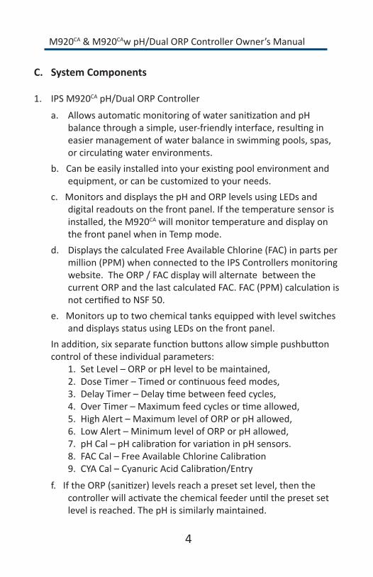
C. System Components
1. IPSM920CA pH/Dual ORP Controller
a. AllowsautomaticmonitoringofwatersanitizationandpHbalancethroughasimple,user-friendlyinterface,resultingineasiermanagementofwaterbalanceinswimmingpools,spas,orcirculatingwaterenvironments.
b.Canbeeasilyinstalledintoyourexistingpoolenvironmentandequipment,orcanbecustomizedtoyourneeds.
c.MonitorsanddisplaysthepHandORPlevelsusingLEDsanddigitalreadoutsonthefrontpanel.Ifthetemperaturesensorisinstalled,theM920CA will monitor temperature and display on thefrontpanelwheninTempmode.
d. DisplaysthecalculatedFreeAvailableChlorine(FAC)inpartspermillion(PPM)whenconnectedtotheIPSControllersmonitoringwebsite. The ORP / FAC display will alternate between the currentORPandthelastcalculatedFAC.FAC(PPM)calculationisnotcertifiedtoNSF50.
e.MonitorsuptotwochemicaltanksequippedwithlevelswitchesanddisplaysstatususingLEDsonthefrontpanel.
Inaddition,sixseparatefunctionbuttonsallowsimplepushbuttoncontroloftheseindividualparameters:
1. SetLevel–ORPorpHleveltobemaintained,2. DoseTimer–Timedorcontinuousfeedmodes,3. DelayTimer–Delaytimebetweenfeedcycles,4. OverTimer–Maximumfeedcyclesortimeallowed,5. HighAlert–MaximumlevelofORPorpHallowed,6. LowAlert–MinimumlevelofORPorpHallowed,7. pHCal–pHcalibrationforvariationinpHsensors.8. FACCal–FreeAvailableChlorineCalibration9. CYACal–CyanuricAcidCalibration/Entry
f.IftheORP(sanitizer)levelsreachapresetsetlevel,thenthecontrollerwillactivatethechemicalfeederuntilthepresetsetlevel is reached. The pH is similarly maintained.
4

M920CA & M920CAw pH/Dual ORP Controller Owner’s Manual
2. Flow Cell with Flow Switch
a. Aninjection-moldedflowcellwithintegratedflow switchhousesthepHandORPsensors,andpartnerswith theM920CA controller to monitor the pH and ORP levels in the water.
b. Theflowswitchverifiesthatwaterisflowingduringafeedcycle,andsendsthecontrollerinstructionstodeactivatethefeedifwaterisnotflowing.
c. Operationofthiscontrollerwithoutafunctioningflow-switchwillvoidtheNSFCertification.Routinelycheckthattheflow-switchisfunctioningbyclosingtheleftvalveonthebottomoftheflow-cell(flowlightshouldturnoff).
3. pH and ORP Sensors
a. pH Sensor – standard (Use only IPS Controllers part # SXPH to maintainNSFCertification)
b. ORPPlatinumSensor–standard(UseonlyIPSControllerspart#SXORPtomaintainNSFCertification)
c. ORPGoldSensor–forusewithSaltChlorinesystems(UseonlyIPSControllerspart#SXORP-GtomaintainNSFCertification)
4. Fittings–tubingconnectors(2)fortappinginstallationofflowcellinput/output
5. In-line Filter with 2-way valves6. Tubing–25feetof3/8”7. MountingBoard–ABSplasticwithmountingholesandstainless
hardware(16”x12”standard,24”x19”optional)8. Temperature Sensor – Senses the current water temperature and
displays the temperature in the display when in Temp mode.9. RemoteMonitoring–WhenconnectedtotheInternetthroughthe
InternalEthernetorwi-ficonnection,thecontrollerwillsenddatatoacentralwebsite.Userscanmonitorcontrolleractivityremotelyandreportonactivityforadaterange.
5

M920CA & M920CAw pH/Dual ORP Controller Owner’s Manual
Figu
re 1:T
hisisa
typicalinstallatio
nusingIPS’sy
stem
package,w
hichcon
sistsofa
n
M92
0CApH/
dualORP
Con
troller,flo
wcellw
ithsw
itch,and
twopu
mpsm
ounted
onthelargebo
ard.
6
Chem
ical
Pum
p
Chem
ical
Pum
p
Flow
cell
(1)
Sucti
on L
ine
FLO
W
FLO
W
FLO
W
Efflue
nt(to
Suc
tion)
Was
te
Influ
ent (
to R
etur
n Li
ne)
Filte
rPu
mp
FLO
W
Filte
r (1
0)
(atta
ch to
pip
e w
ith c
lam
ps)
FLO
W
FLO
W
Sam
ple
pH se
nsor
(3)
ORP
Sens
or(4
)
Typi
cal I
nsta
llatio
nN
ote:
All
chem
ical
mus
t be
inje
cted
dow
nstr
eam
from
the
heat
er a
nd fl
owce
ll.
Mai
n Dr
ain
and
Skim
mer
Pres
sure
Diff
eren
tial
Retu
rn L
ineFC
100G
FLSW
SXPH
SXO
RP
SXO
RP-G
Valv
eJa
co F
itting
1/2
”
Jaco
Fitti
ng 1
/4”
38tu
bing
Filte
r
1 2 3 4 5* 6 7 8 9 10
Flow
Cel
l, Co
mpl
ete
Flow
Sw
itch
Onl
ypH
Sen
sor
ORP
Sen
sor (
Stan
dard
Plati
num
Tip
)O
RP S
enso
r (Go
ld-T
ipfo
r Sal
t Poo
ls)2-
way
Flo
w C
ell V
alve
1/2”
Jaco
fitti
ng fo
rse
nsor
s1/
4” Ja
co fi
tting
for
tubi
ng3/
8” tu
bing
for
plum
bing
to/f
rom
Fl
ow C
ell
Filte
r Str
aine
r
IPS
Part
s Lis
t
Flow
Sw
itch
(2)
1/2”
Jaco
Fitti
ng (7
)
38tu
bing
(9)
Valv
e (6
)
* no
t sho
wn
1/4”
Jaco
Fitti
ng(7
)
M920CA & M920CAw pH/Dual ORP Controller Owner’s Manual
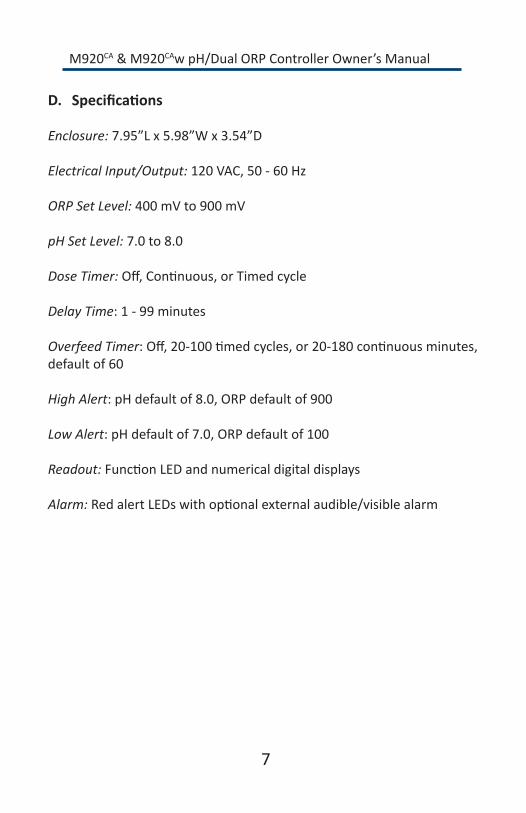
D. Specifications
Enclosure:7.95”Lx5.98”Wx3.54”D
Electrical Input/Output:120VAC,50-60Hz
ORP Set Level:400mVto900mV
pH Set Level:7.0to8.0
Dose Timer:Off,Continuous,orTimedcycle
Delay Time:1-99minutes
Overfeed Timer:Off,20-100timedcycles,or20-180continuousminutes,defaultof60
High Alert:pHdefaultof8.0,ORPdefaultof900
Low Alert:pHdefaultof7.0,ORPdefaultof100
Readout:FunctionLEDandnumericaldigitaldisplays
Alarm:RedalertLEDswithoptionalexternalaudible/visiblealarm
7

M920CA & M920CAw pH/Dual ORP Controller Owner’s Manual
E. ControllerPanelDescriptions
1. DigitalDisplaysandFunctionLEDs
a. pH
1. Alert - red LED2. Dose-greenLED
b. ORP/FAC
1. Alert - red LED2. Dose 1 - yellow LED3. Dose 2 - yellow LED
Figure 2:M920CAControllerComponentsConnections
8
ElectricalConnections
Flow CellConnections
digital display
pushbutton
LEDs
Controller Communication
M920CA & M920CAw pH/Dual ORP Controller Owner’s Manual
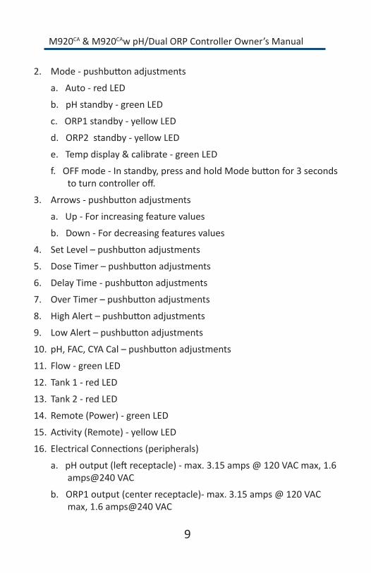
2. Mode-pushbuttonadjustments
a. Auto - red LED
b.pHstandby-greenLED
c. ORP1 standby - yellow LED
d. ORP2 standby - yellow LED
e.Tempdisplay&calibrate-greenLED
f.OFFmode-Instandby,pressandholdModebuttonfor3secondstoturncontrolleroff.
3. Arrows-pushbuttonadjustments
a.Up-Forincreasingfeaturevalues
b.Down-Fordecreasingfeaturesvalues
4. SetLevel–pushbuttonadjustments
5. DoseTimer–pushbuttonadjustments
6. DelayTime-pushbuttonadjustments
7. OverTimer–pushbuttonadjustments
8. HighAlert–pushbuttonadjustments
9. LowAlert–pushbuttonadjustments
10. pH,FAC,CYACal–pushbuttonadjustments
11. Flow-greenLED
12. Tank 1 - red LED
13. Tank 2 - red LED
14. Remote(Power)-greenLED
15. Activity(Remote)-yellowLED
16. ElectricalConnections(peripherals)
a.pHoutput(leftreceptacle)-max.3.15amps@120VACmax,1.6amps@240VAC
b.ORP1output(centerreceptacle)-max.3.15amps@120VACmax,1.6amps@240VAC
9

M920CA & M920CAw pH/Dual ORP Controller Owner’s Manual
c.ORP2output(rightreceptacle)-max.3.15amps@120VACmax,1.6amps@240VAC
d.ACpower-120VAC,50-60Hz
e.Flow-fromflowcell
f.Tank1-fromtanklevelswitch(optional)
g.Tank2-fromtanklevelswitch(optional)
h.Externalaudible/visiblealarm(optional)
i.pHsensor-BNCconnection
j.ORPsensor-BNCconnection
k.OptionaldrycontactORP1output(contactfactoryforinstructions)
F.ElectricalDescriptions1. Power
a.120VAC,50-60Hz,3-wiregroundedNEMA5powercord.GFCIsourcerequired.Note:Thereisanoptiontoconvertto240VACinput/output.
2. DipSwitches(1-4)-SeeFigure3.
a. 1:pH/ORPinterlock(default:OFF)
NoORP1orORP2feedifpHisfeeding(ON).
b. 2:pH/ORPalertinterlock(default:ON)
NoORP1orORP2ifpHisinalertmode(ON).
c. 3:Acid/Basedefaultacid(default:OFF)
1. FeedbasechemicalwhenpHlevelfallsbelowsetpoint.(ON)2. FeedacidchemicalwhenpHabovesetpoint.(OFF)
d. 4:Notinuse.
Figure 3: Dipswitches
10

M920CA & M920CAw pH/Dual ORP Controller Owner’s Manual
II. InstallationA. Setup(Installationvideoavailableatipscontrollers.com)1. Turnoffallperipheralequipmentsuchasheaters,chemicalfeeders,
and pumps.
2. Relievepressurefromthefiltrationsystem.
B. Tools1. Cordless drill
2. 1/4”NPTTap
3. 7/16”drillbit
4. 1/4”or3/8”drillbitforTempSensor
5. Masonrydrillbitandanchors,orotherappropriatefasteners
6. 13/16”wrenchorchannel-lockpliers
C. Procedure1. Location
a. Wall area with easy access
b. Within8feetoffeeder
c. Atleast10feetfromwateredge
d. Closeproximitytotimeclock
e. Within6feetofGFCIpowersource
2. Mounting
a. Controllerandflowcellarefactory-mountedtoABSboardforyour convenience.
b. SecurelymountABSmountingboardwithM920CA controller and flowcellonwall(verticalinstallation).
c. Ifapplicable,securelyattachtheperistalticpumpstotheoptionallargerABSmountingboardwiththeprovidedhardware.
11

M920CA & M920CAw pH/Dual ORP Controller Owner’s Manual
d. Drilla7/16”holeandtapa1/4”NPTporttoalocationdown-streamfromthefilterandupstreamfromtheheaterandanychemicalintroductionpoints.Installatubingconnectorandflextubingtobeconnectedtotheleftsideflowcellportcontainingtheflowswitch.Thein-linefilterwillalsobeinstalledinthislineandmountedtoahorizontalpipewithbandclamps(included).Note: Verifythatthefilterisinstalledwithdirectionalarrowspointinginthedirectionoftheflow.
e. Drilla7/16”holeandtapa1/4”NPTporttoalocationthatissubjecttovacuumorreducedpressure(afterheater).Installatubingconnectorandflextubingtobeconnectedtotherightsideflowcellport.Note:Werecommendthatthistubingcon-nectorbeinstalledintothedrainholeonthesuctionsideofthe pump for best performance.
f. Cuta3”-6”lengthofflextubingandinsertintotheflowcell’ssamplestreamport(center).
3. pH and ORP Sensors Note: Carefully unpack the pH and ORP sensors and set aside in a clear areauntilreadytoinstallintotheflowcell.
a. VerifythattheM920CA controller power is OFF.
b. Removetheplasticprotectivecapsfromthesensorsandstoreinaseparatelocationforfuturere-use.
c. Slidetheglassendofeachsensor(pHandORP)intooneofthecompressionfittingslocatedatthetopoftheflowcell.Ensurethatthetipissubmergedintothewatertowithin1/2”fromthebottomoftheflowcell.Handtighteneachnutfitting.
4. Temperature Sensor
a. Drilla1/4”or3/8”inchhole(dependingonthesensorsize)afterthefilterandbeforetheheater.
b. Insert the temperature sensor into the drilled hole and secure withabandclamp(included).
12

M920CA & M920CAw pH/Dual ORP Controller Owner’s Manual
c. Runthesensorcableintothecontrollerthroughthestrainreliefmarked“temp”andconnecttotheterminalblockonthefrontcircuitboardmarked“Temp”.
5. RemoteMonitoringEthernetConnection
a. RuntheEthernetcablewithconnectorintotheM920CA throughthelargeststrainreliefconnectoronthebottomortheenclosure.
b. ConnecttotheEthernetconnectoronthefrontcircuitboard.
c. Whenavalidconnectionismade,thegreen“Remote”LEDwilllightupandtheorange“Activity”LEDwillblinkintermittently.
6. ElectricalConnections(Shouldbecompletedbyalicensedelectrician)
a. VerifythattheM920CA controller power is OFF.
b. ConnectthepHfeederconnectiontotheappropriateperistalticpump or other device.
c. ConnecttheORPfeederconnectiontotheappropriateperistalticpumporotherdevice.Note: There is another connectionportforORP2.
d.Method1(recommended):ConnecttheACpowercordtotheload-sideofthecirculationpumpcircuit.ThiswillonlyprovidepowertotheM920CAwhenthecirculationpumpisrunning.
e. Method2:ConnecttheACpowercordtoaGFCIpowersource.
f. ConnectthepHsensorconnectortothecorrespondinglowerport(labeledpH)attherightedgeofthecontroller.
g. ConnecttheORPsensorconnectortothecorrespondingupperport(labeledORP)attherightedgeofthecontroller.
7. OptionalconnectiontoaSaltChlorineGenerator(SCG) TheM920CAcontrolleriscapableofcontrolling(turningon/off)aSCGdependingonthecurrentORPreading.Thisactioncanbeaccomplishedthroughtheuseofa120Vor240Vrelay,orbycon-nectingtheSCGtothe“normallyopen”drycontactrelay(ORP1)includedwiththeM920CAcontroller.Contactthefactoryformoreinformation.
13

M920CA & M920CAw pH/Dual ORP Controller Owner’s Manual
14
8. ConvertingfromCordtoPermanentConnection
a. Remove cover.
b. LoosenstrainreliefglandfromACcord.
c. Usinga3/32”(2.44mm)slotscrewdriver,carefullyloosenterminalsthatattachtheACcordtothecontrollerbox.
d. Remove the AC cord.
e. ReplacetheACcordwithaminimumjacketedcordof18/3AWGSW105º900V,thencarefullyhandtightentheterminalsonthestrainreliefgland.Note:Forliquidtightinstallationconnections,replacethestrainreliefglandwithaliquidtightconnectoranduseaminimumstrandedwiregaugeof18AWG105º600V(do not use solid conductor) foreachconductor:Black(hot),White(common),andGreen(ground).
Important:
Theminimumallowableconductorsizeis18AWGwithanampacityof10AMPS,andagroundfaultinterruptcircuitbreakerof15-20AMPS.
Use stranded copper wire only.
9. Continuetothenextsectionfortheconnectionrequirementsforremotemonitoring.TheremotemonitoringmoduleandtheInternetare needed to complete this process.

M920CA & M920CAw pH/Dual ORP Controller Owner’s Manual
15
D. ConnectionRequirementsforRemoteMonitoring
1. IPS-M920CAw(Wi-Fi)
TheremotemonitoringmoduleusedwiththeIPS-M920CAw (or the RX-365wusedwiththeIPS-M820)isaWi-FidevicewhichwillaccessanexistingWi-Finetworktosendcontrollerdatatothecentralmonitoringwebsite.
IfanexistingWi-Finetworkisnotavailable,aMiFior“cellularhotspot”canbeadded(contactalocalwirelessprovider).
Note:TheEthernetconnectorontheM920CAw is disabled and cannot be used.
a. Howitworks: Theremotemonitoringmoduleisprogrammedto“wakeup”atacustomer-determinedinterval(minutes)tosendallcurrentreadings,settings,andalertstoIPSControllers’remotemonitoringwebsite.
Becausethedataisbeingsenttothewebsiteratherthanthewebsitepullingthedatafromthemodule,theportisnotleftopenandastaticIPAddressisnotneeded.Thisshouldaddressanyconcernsregardingfirewallsecurity.
Whenchangesaremadetothecontrollersettingsremotely,thenewsettingsaredeliveredbacktotheremotemonitoringmoduleonitsnextscheduledconnection.
b. Setup-GotoSectionIV-AonPage28forinstallationinstructions.
2. IPS-M920CA(Hardwire)
TheremotemonitoringmoduleincludedwiththeIPS-M920CA (or the RX-365usedwiththeIPS-M820)requires:• AnEthernetconnectionprovidedbyahardwiredirectlyfroma
router,• AWi-FitoEthernetAdapter,• OraCellularModem(requirescarrierservicesuchasVerizonor
AT&T).

M920CA & M920CAw pH/Dual ORP Controller Owner’s Manual
16
TheprovidedconnectionmustallowtheremotemonitoringmoduletoaccesstheInternetwithoutprovidinganyusernames,passwords,etc.viaPort80foroutbounddataonly.
ThebesttestforthisabilityistoconnectalaptoptotheEthernetcableandopenawebbrowser.Ifthebrowsercanopendirectlytothewebwithoutcredentials,theconnectionwillfunctionproperlyfortheremotemonitoringmodule(laptopWi-Fishouldbeturnedoffwhendoingthistest).
a. Howitworks: Theremotemoduleisprogrammedto“wakeup”atacustomerdeterminedinterval(minutes)andsendallcurrentreadings,settings,andalertstotheIPSControllersremotemonitoringwebsite.
Becausethedataisbeingsenttothewebsiteratherthanthewebsitepullingthedatafromthemodule,theportisnotleftopenandastaticIPAddressisnotneeded.Thisshouldaddressanyconcernsregardingfirewallsecurity.
Whenchangesaremadetothecontrollersettingsremotely,thenewsettingsaredeliveredbacktotheremotemonitoringmoduleonitsnextscheduledconnection.
b. Setup-GotoSectionIV-BonPage30forinstallationinstructions.

M920CA & M920CAw pH/Dual ORP Controller Owner’s Manual
III. OperationA. Startup and Shutdown1. Startup
a. ProvidepowertotheM920CAusingeitherMethod1or2asdiscussedinstep6dor6eonpage13.
b. Turnonthefilterpumpandverifythewaterflowthroughtheflowcellbyopeningthesampleportvalve(center)andobservingasteadystreamofwater.Therightsidevalvemayneedtobepartiallyclosedtoproduceasteadystream.Note: WatershouldpassoverthepHandORPsensorsforaminimumof5minutestoallowforaccurate,stablereadingsofpHandORPlevelsfromthepoolorspa.ORPreadingsmaytakelongerto stabilize.
c. Checkforleaksandrepairifnecessary.
d. Manually adjust and balance the pool or spa water to acceptable rangesusingatestkit.Note(s):1.UseaDPDbasedtestkittocheckthechlorinelevel.2.CyanuricAcid(Conditioner)levelsshouldnotexceed50ppmforbestresults.
e. VerifythatthegreenFlowLEDisilluminated.BoththepHandORPdoseoutputsaredisabledifthereisnowaterflow.
f. PresstheModepushbuttonmomentarilytoplacethecontrollerintothepHstandbymode.ThegreenpHstandbyLEDwillilluminate.SelectthedesiredpHsetlevelanddosetime(continuousortimed).
g. WhilestillinthepHstandbymode,pressthepHCalpushbuttontocalibratethereadingtothevalueobservedthroughthemanualtestingofthewater.Note:Alwayscalibrateusingwaterfromthesampleportoftheflowcell.
h. PresstheModepushbuttonmomentarilytoplacethecontrollerin ORP1 standby mode. The yellow ORP1 standby LED will illuminate.SelectthedesiredORP1setlevelanddosetime(continuousortimed).
17

M920CA & M920CAw pH/Dual ORP Controller Owner’s Manual
i. PresstheModepushbuttonmomentarilyuntiltheredAutoLEDis illuminated.
2. Shutdown
Note:EachtimetheModepushbuttonismomentarilypressed,themodewillcyclefromAutotopHtoORP1toORP2,Temp,andthenreturn to Auto mode.
a. PresstheModepushbuttonmomentarilytoplacethecontrollerinpHstandbymode.ThegreenpHstandbyLEDwillilluminate,andboththepHandORPdigitaldisplayswillshowdashes.
b. PressandholdtheModepushbuttonfor2secondsuntilboththepHandORPdigitaldisplaysreadOFF.
c. ReleasetheModepushbutton.TheM920CA controller will turn off,andthedigitaldisplaysandfunctionLEDswillgoblank.ThegreenFlowLEDwillbeilluminatedifwaterisflowingthroughtheflowcell.
B. Modes and Adjustments1. Auto
a. ThisisthenormaloperationalmodeoftheM920CA controller.
b. ThecontrollerallowsfulloperationandmonitoringofbothpHand ORP levels.
c. Nofunctionpushbuttonsareoperationalinthismode.
d. TheredfunctionLEDnexttoAutoisilluminated.
e. pHandORPdigitaldisplaysmonitorthesensorinputlevels.
2. pH standby
Note:Whileinthismode,thegreenpHstandbyLEDwillilluminate,boththepHandORPdigitaldisplayswillshowdashes,andallAutofunctionswillbedisabled.Whenafunctionpushbuttonispressed,thecorrespondingdigitaldisplaywillshowthefunction.UsetheUporDownarrowbuttonstothelefttoincreaseordecreasethefunctionvalue.
18

M920CA & M920CAw pH/Dual ORP Controller Owner’s Manual
a. Set Level
1. Default:7.4pH2. Selectablerange:7.0–8.0pH(in0.1increments)
b. Dose Timer
1. Default:Timeddoseof10-secondpHfeedrelayenergizedand5minutespHfeedrelayde-energized.Inthetimeddosecyclemode,thedoseLEDwillflashwhiledosingandilluminatesteadilyduringthedelayportionofthetimedcycle.Incontinuousdosemode,thedoseLEDwillflashwhiledosing.
2. Selectablerange:OFF,CON(continuous),andTimed(0.6–900secondsONand5minutesOFF)
c. Delay Time
1. Default:Delaytimeof5minutesbetweenfeedcycles(timedfeedonly).Afterdosetime,thecontrollerwillwait(delay)forthespecifiedminutesbeforecheckingthecurrentlevelanddosingagainifnecessary.
2. Selectablerange:1-99minutes.
d. Over Timer
1. Default:ON.Theoverfeedtimerdoesnotautomaticallyreset.ItmustberesetbypressingtheModebuttontocyclethroughtheStandbymodeandbacktotheAutomode.
2. TheOverfeedtimerisinterlockedwiththeDoseTimerselec-tion.i. IftheDoseTimerissettoatimedcycle,theOverTimer
willcounttimedfeedcycles.Whenthepresetcycleisreached,thepHdigitaldisplaywillflashandthepHoutputrelaywillde-energize.Defaultis60cycles.
-Selectablerange:5to100cycles
ii. IftheDoseTimerissettoacontinuousfeedmode,theOverTimerwillcountinminutes.Defaultis60minutes.
-Selectablerange:20to180minutes
19

M920CA & M920CAw pH/Dual ORP Controller Owner’s Manual
3. WhentheDoseTimerischangedfromeithertimedorcon-tinuousfeed,theOverTimerisresettoDefault.
4.TurningofftheOverTimerwillvoidanyNSFCertification.
e. HighAlert
1. Default:8.0pH2. Selectablerange:OFF,7.5pHto8.4pH(acidfeed).Ahigh
alertwilloccurifthepHlevelremainsabovetheHighAlertlevelfor10continuousminutes,andwillautomaticallyturnofftheHighAlertwhenthepHlevelfallsbelowthehighalertlevelfor1continuousminute.DuringHighAlert,thepHdoseoutput will be disabled.
f.LowAlert
1. Default:7.0pH2. Selectablerange:OFF,6.8pHto7.4pH(acidfeed).Alow
alertwilloccurifthepHlevelremainsbelowtheLowAlertlevelfor10continuousminutes,andwillautomaticallyturnofftheLowAlertwhenthepHlevelrisesabovethelowalertlevelfor1continuousminute.DuringLowAlert,thepHdoseoutput will be disabled.
g.pHCal
1. Default:0-voltsensorinput,displays7.0pH2. Selectablerange:Witha0-voltsensorinput,thedisplayis
adjustablefrom6.1pHto7.9pH.3. ORP1 standby
Note:Whileinthismode,theyellowORP1standbyLEDwillilluminate,boththepHandORPdigitaldisplayswillshowdashes,andallAutofunctionswillbedisabled.UsetheUporDownarrowbuttonstothelefttoincreaseordecreasethefunctionvalue.
a. Set Level
1. Default:650mV2. Selectablerange:400mVto900mV(in5mVincrements)
20

M920CA & M920CAw pH/Dual ORP Controller Owner’s Manual
b. Dose Timer
1. Default:10-secondORPfeedrelayenergizedand5minutesORPfeedrelayde-energized(timeddosetimer).Inthetimeddosecyclemode,thedoseLEDwillflashwhiledosing,andwillilluminatesteadilyduringthedelayportionofthetimedcycle.Incontinuousdosemode,thedoseLEDwillflashwhiledosing.
2. Selectablerange:OFF,CON(continuous),andTimed(0.6to900secondsONand5minutesOFF)
c. Delay Time
1. Default:Delaytimeof5minutesbetweenfeedcycles(timedfeedonly).Afterdosetime,thecontrollerwillwait(delay)forthespecifiedminutesbeforecheckingthecurrentlevelanddosingagainifnecessary.
2. Selectablerange:1-99minutes.
d. Over Timer
1. Default:ON.Theoverfeedtimerdoesnotautomaticallyreset.Itmustberesetbyturningthecontrolleroff,thenon.
2. TheOverfeedtimerisinterlockedwiththeDoseTimerselection.i. IftheDoseTimerissettoatimedcycle,theOverTimer
willcounttimedfeedcycles.Whenthepresetcycleisreached,theORPdigitaldisplaywillflashandtheORP1outputrelaywillde-energize.Defaultis60cycles.
-Selectablerange:5to100cycles
ii. IftheDoseTimerissettoacontinuousfeedmode,theOverTimerwillcountinminutes.Defaultis60minutes.
-Selectablerange:20to180minutes
3. WhentheDoseTimerischangedfromeithertimedorcontinuousfeed,theOverTimerisresettoDefault.
4. TurningofftheOverTimerwillvoidanyNSFCertification.
21

M920CA & M920CAw pH/Dual ORP Controller Owner’s Manual
e. HighAlert
1. Default:900mV2. Selectablerange:650mVto900mV,noOFF.Ahighalertwill
occuriftheORPlevelremainsabovetheHighAlertlevelfor10continuousminutes,andwillautomaticallyturnofftheHighAlertwhentheORPlevelfallsbelowthehighalertlevelfor1continuousminute.DuringHighAlert,theORP1doseoutput will be disabled.
f.LowAlert
1. Default:100mV2. Selectablerange:OFF,100mVto640mV.Alowalertwill
occuriftheORPlevelremainsbelowtheLowAlertlevelfor10continuousminutes,andwillautomaticallyturnofftheLow Alert when the ORP level rises above the low alert level for1continuousminute.DuringLowAlert,theORP1doseoutput will be disabled.
g. FACCal
1. Defaultis.0andwillnotchangeifcontrollerisnotcommuni-catingwiththemonitoringwebsite.
2. CalculatedFreeAvailableChlorine(ppm)willdisplayfromwebsiteandcanbecalibratedin.1increments(+/-).Whencalibratingdown,arrowpast“OFF”orthePPMdisplaywillbeturnedoff.
3. ValueiscalculatedusingpH,ORP,Temp,andCYA.*FAC(PPM)calculationisnotcertifiedtoNSF50.
4. ORP2 standby Note:Whileinthismode,theyellowORP2standbyLEDwillilluminate,boththepHandORPdigitaldisplayswillshowdashes,andallAutofunctionswillbedisabled.UsetheUporDownarrowbuttonstothelefttoincreaseordecreasethefunctionvalue.
a. Set Level1. Default:640mV2. Selectablerange:400mVto890mV(in5mVincrements),
cannotbesetforlessthan10mVbelowtheORP1setlevel.
22

M920CA & M920CAw pH/Dual ORP Controller Owner’s Manual
23
b. Dose Timer
1. Default:OFF.Inthetimeddosecyclemode,thedoseLEDwillflashwhiledosingandilluminatesteadilyduringthedelayportionofthetimedcycle.Incontinuousdosemode,thedoseLEDwillflashwhiledosing.
2. Selectablerange:OFF,CON(continuous),andTimed(0.6to900secondsONand5minutesOFF)
c. Delay Time
1. Default:OFF.Delaytimeof5minutesbetweenfeedcycles(timedfeedonly).Afterdosetime,thecontrollerwillwait(delay)forthespecifiedminutesbeforecheckingthecurrentlevelanddosingagainifnecessary.
2. Selectablerange:1-99minutes.
d. Over Timer
1. Default:ON.Theoverfeedtimerdoesnotautomaticallyreset.Itmustberesetbyturningthecontrolleroff,thenon.
2. TheOverfeedtimerisinterlockedwiththeDoseTimerselection.i. IftheDoseTimerissettoatimedcycle,theOverTimer
willcounttimedfeedcycles.Whenthepresetcycleisreached,theORPdigitaldisplaywillflashandtheORP2outputrelaywillde-energize.Defaultis60cycles.-Selectablerange:5to100cycles
ii. IftheDoseTimerissettoacontinuousfeedmode,theOverTimerwillcountinminutes.Defaultis60minutes.-Selectablerange:20to180minutes
3. WhentheDoseTimerischangedfromeithertimedorcontinuousfeed,theOverTimerisresettoDefault.
4. ORP2willnotflashORPdigitaldisplayifORP2overfeedoccurs).
5. TurningofftheOverTimerwillvoidanyNSFCertification.
e. HighAlertcontrolledbyORP1.
f. LowAlertcontrolledbyORP1.

M920CA & M920CAw pH/Dual ORP Controller Owner’s Manual
24
g. CYACal
• Defaultis0
• TestedCYAlevelmustbeenteredforaccurateFAC/ppmCal-culation.CYAshouldbetestedandenteredatleastmonthly.
5. Temp Mode
a. WaterTemperaturewillbedisplayedifthetemperaturesensoris installed. Display will show the water temp when Temp mode isenteredandwillnotchangewhiledisplayed.
b. TemperaturecanbecalibratedbyusingtheUp/Downarrowkeys(+/-10degrees).
c. DisplaycanbechangedfromFahrenheittoCelsiusbypressingthepHCalbutton.
6. Flow
a. Thecontrollerandflowcellareshippedpre-mountedtoasmall(16”x12”)orlarge(24”x19”)ABSplasticboard.Theintegratedflowswitchispre-wiredtothecontroller.
Figure 4: Flow Switch Terminal
b. Theflowswitchmustbeinstalledforsafetyreasonstopreventdosingchemicalswhenthereisnoflowinthecirculationpiping.
c. Priortoinstallation,thecontrolleroperationcanbetestedbytiltingthepopulatedmountingboarduntilthecontroller’sgreenlightturnson(flowswitchmagnetattheswitch’stop).
7. HiddenFeatures-SeeFigure5.
Figure 5: Hiddenbutton

M920CA & M920CAw pH/Dual ORP Controller Owner’s Manual
a. TheUp/Downbuttonscanbelockedouttopreventunauthorizedchangestothesettings.Thereisahiddenbuttonbehindthe“0”inIPS-M920CAonthefrontoverlay.PlacetheM920CA into standby mode and then press and hold the hidden buttonfor2seconds,untilthedisplayindicates“LocOn”andtheUp/Downkeysdonotoperate.Allotherfeaturebuttonswillworktodisplaycurrentsettings.Turnthelockoffbyholdingthehiddenbuttondownfor2secondsuntilthedisplayindicates“LocOff”.
b. TheM920CAcanbeforcedtomanuallydosepH,ORP1,orORP2byplacingtheM920CA into the standby mode that is desired (pH,ORP1,ORP2),andthensimultaneouslyholdingdownthedosetimerbuttonanddelaytimebutton.theM920CA will dose forthetimesetinthedosetimesetting(timed-feedonly).
8. Factorydefaults Toreturnthecontrollertothefactorydefaults:
a. Place the controller in Standby Mode. b. TurnoffthecontrollerbyholdingdowntheMode
pushbutton.c. PressandholdboththeSetLevelandpHCalpushbuttons,
andthenpresstheModepushbutton.BoththepHandORPdisplayswillshow“Ld”.Thecontrollerwillbereturnedtothefactorydefaultfunctions,andbeplacedinthetestmode.
d. ReturnthecontrollertofulloperationbyagainturningoffthecontrollerwiththeModepushbutton.TurnthecontrolleronagainbypressingtheModepushbutton.Note: Failure tocompletethisactionwillleavethecontrollerinthetestmode.
25

M920CA & M920CAw pH/Dual ORP Controller Owner’s Manual
C. Maintenance1. Winterizing(extendedshutdownsorcolderclimates)
a. TurnofftheM920CAcontrollerandshutoffmainpowertocontroller.
b. GentlyremovethephandORPsensorsfromtheflowcell.Filltheprovidedprotectivecaps(removedduringinstallation)withwaterandre-installontoeachsensor,andstoreinawarm,securelocation.Sensorendsmustremaininwaterforthedurationofthestoragetime.
c. Drainthewaterfromtheflowcell.
2. Cleaningthesensortips
Note:Itisimportanttokeepthesensortipscleaninordertoensureaccuratereadings.
a.Sensortipsshouldbecleanedevery3to6monthsforcommer-cialpoolsandspas,andevery6to9monthsforresidentialpoolsandspas.Determinethenecessaryfrequencybycomparingthereadingsbeforeandafterthecleaning.Identicalreadingsmeanthatthecleaningtimecanbeextended.
b. TurnofftheM920CA controller.
c. Closetherightandleftvalvesatthebottomoftheflowcell.
d. Loosenthenutfittingonthesensorandgentlyremoveitfromtheflowcell.
e. Swirlthesensortipinasolutionofliquiddishsoapandwaterfor30secondsandrinsewithwater.
f. Swirlthesensortipfor5secondsinMuriaticacidorwhitevinegarandrinsewithwater.Note: Do not touch or brush the sensortip.
g. Gentlyre-insertthesensorintotheflowcellandhandtightenthenutfitting.
h. TurnontheM920CA controller.
26

M920CA & M920CAw pH/Dual ORP Controller Owner’s Manual
27
i. Opentheflowcellvalvesandwaitforafewminutesforthesystemtostabilizeandgetanaccuratereading.AdjusttheSetLevelifnecessary.
3. CheckingtheORPsensor
a. TheORPsensormustbecheckedevery6months,orafteranover-sanitizationevent.
b. Cleanthesensortipasshownintheprevioussection.
c. Placethesensorinacleanglassoftapwater.Thereadingshouldshowbetween200mVand400mV.
d. AfteraddingapinchofDichlororTrichlorintothewater,thereadingshouldshowbetween750mVand800mV.Note: if a sanitizerwithhighpHisusedinplaceofDichlororTrichlor,thereadingshouldshowbetween650mVand750mV.
e. Ifthesensordoesnotshowtheindicatedreadings,thenitmustbe replaced.
4. CheckingthepHsensor
a. ThepHsensormustbecheckedevery6months,orafteranyincidentwhenthepHlevelgoesoutofrange.
b. Placethesensorinacleanglassoftapwater.
c. Addasmallamountofacidtothewaterandtakeareading.Itshould show a low number.
d. Placethesensorintoasolutionthatishigherthan7.5pH,andverifythatthereadingisincreasing.
e. Ifthesensordoesnotshowtheindicatedreadings,thenitmustbe replaced.
M920CA & M920CAw pH/Dual ORP Controller Owner’s Manual
28
IV. IPS-M920CA Wi-Fi SetupA. Smart Phone Wi-Fi Setup1. TurnontheIPS-M920CA.
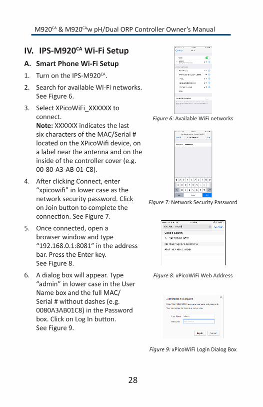
2. SearchforavailableWi-Finetworks.SeeFigure6.
3. Select XPicoWiFi_XXXXXX to connect. Note: XXXXXX indicates the last sixcharactersoftheMAC/Serial#locatedontheXPicoWifidevice,ona label near the antenna and on the insideofthecontrollercover(e.g.00-80-A3-AB-01-C8).
4. AfterclickingConnect,enter“xpicowifi”inlowercaseasthenetwork security password. Click onJoinbuttontocompletetheconnection.SeeFigure7.
5. Onceconnected,openabrowser window and type “192.168.0.1:8081”intheaddressbar. Press the Enter key. SeeFigure8.
6. Adialogboxwillappear.Type“admin”inlowercaseintheUserNameboxandthefullMAC/Serial#withoutdashes(e.g.0080A3AB01C8)inthePasswordbox.ClickonLogInbutton. SeeFigure9.
Figure 6: Available WiFi networks
Figure 7: Network Security Password
Figure 8: xPicoWiFi Web Address
Figure 9: xPicoWiFiLoginDialogBox
M920CA & M920CAw pH/Dual ORP Controller Owner’s Manual
29
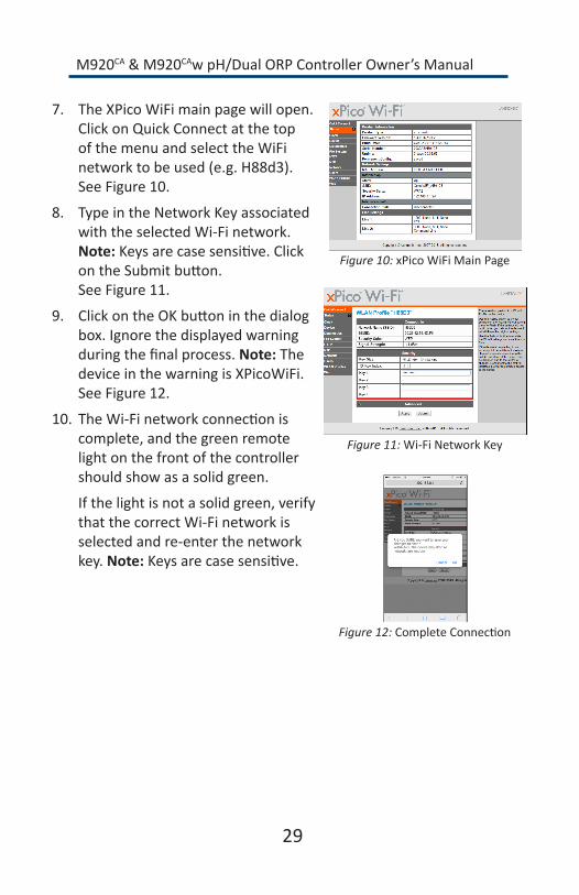
7. TheXPicoWiFimainpagewillopen.Click on Quick Connect at the top ofthemenuandselecttheWiFinetworktobeused(e.g.H88d3).SeeFigure10.
8. Type in the Network Key associated with the selected Wi-Fi network. Note:Keysarecasesensitive.ClickontheSubmitbutton. SeeFigure11.
9. ClickontheOKbuttoninthedialogbox.Ignorethedisplayedwarningduringthefinalprocess.Note: The deviceinthewarningisXPicoWiFi.SeeFigure12.
10. TheWi-Finetworkconnectioniscomplete,andthegreenremotelightonthefrontofthecontrollershouldshowasasolidgreen.
Ifthelightisnotasolidgreen,verify that the correct Wi-Fi network is selected and re-enter the network key. Note:Keysarecasesensitive.
Figure 10: xPicoWiFiMainPage
Figure 11: Wi-Fi Network Key
Figure 12:CompleteConnection
M920CA & M920CAw pH/Dual ORP Controller Owner’s Manual
30
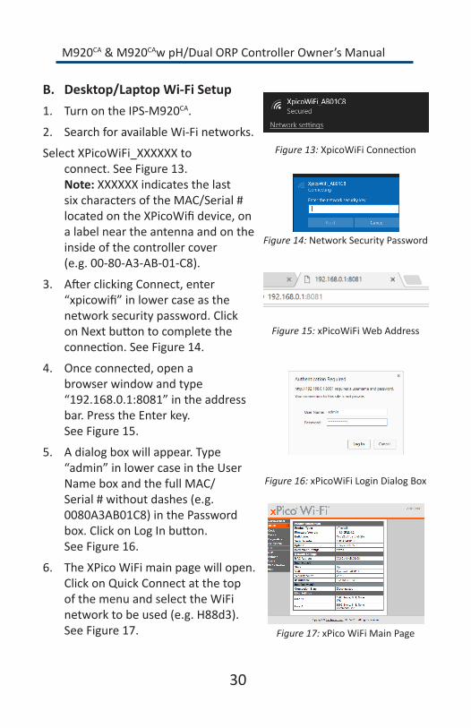
B. Desktop/LaptopWi-FiSetup1. TurnontheIPS-M920CA.
2. SearchforavailableWi-Finetworks.
Select XPicoWiFi_XXXXXX to connect.SeeFigure13. Note: XXXXXX indicates the last sixcharactersoftheMAC/Serial#locatedontheXPicoWifidevice,ona label near the antenna and on the insideofthecontrollercover (e.g.00-80-A3-AB-01-C8).
3. AfterclickingConnect,enter“xpicowifi”inlowercaseasthenetwork security password. Click onNextbuttontocompletetheconnection.SeeFigure14.
4. Onceconnected,openabrowser window and type “192.168.0.1:8081”intheaddressbar. Press the Enter key. SeeFigure15.
5. Adialogboxwillappear.Type“admin”inlowercaseintheUserNameboxandthefullMAC/Serial#withoutdashes(e.g.0080A3AB01C8)inthePasswordbox.ClickonLogInbutton. SeeFigure16.
6. TheXPicoWiFimainpagewillopen.Click on Quick Connect at the top ofthemenuandselecttheWiFinetworktobeused(e.g.H88d3).SeeFigure17.
Figure 13:XpicoWiFiConnection
Figure 14: Network Security Password
Figure 15: xPicoWiFi Web Address
Figure 16:xPicoWiFiLoginDialogBox
Figure 17:xPicoWiFiMainPage

M920CA & M920CAw pH/Dual ORP Controller Owner’s Manual
7. Type in the Network Key associated with the selected Wi-Fi network. Note:Keysarecasesensitive.ClickontheSubmitbutton. SeeFigure18.
8. ClickontheOKbuttoninthedialogbox.Ignorethedisplayedwarningduringthefinalprocess.Note: The deviceinthewarningisXPicoWiFi.SeeFigure19.
9. TheWi-Finetworkconnectioniscomplete,andthegreenremotelightonthefrontofthecontrollershouldshowasasolidgreen.
Ifthelightisnotasolidgreen,verify that the correct Wi-Fi network is selected and re-enter the network key. Note:Keysarecasesensitive.
Figure 18: Wi-Fi Network Key
Figure 19:CompleteConnection
31

M920CA & M920CAw pH/Dual ORP Controller Owner’s Manual
32
V. Troubleshooting
A. Chlorine/Bromineleveltoolow1. ORP Set level is too low:CheckSanitizerlevelwithtestkitandadjust
Set Level as necessary
2. Chemical feed rate too low:Increasethefeedrate.
3. Chemical feeder is empty:Refillthefeeder.
4. Chemical check valve/injector is clogged:Switchacidfeedtubetochlorine injector to clean.
5. Feed pump malfunction:Repairthefeedpump.
6. Sensor malfunction: Replace sensor.
B.Chlorine/Bromineleveltoohigh1. ORP Set level is too high:CheckSanitizerlevelwithtestkitand
adjust Set Level as necessary.
2. Sensor tip is dirty:Cleanaccordingtomaintenance instructions.
C.pHleveltoolow1. pH Set level is too low: Check pH level with test kit and adjust Set
Level as necessary.
2. Chemical feed rate too high:Lowerfeedrate.
3. Chemical feeder is empty (base):Refillthefeeder.
4. Sensor malfunction: Replace sensor.
D.pHleveltoohigh1. pHSetLevelistoolow:CheckpHlevelwithtestkitandadjustSet
Level as necessary.
2. Sensor tip is dirty:Cleanaccordingtomaintenance instructions.
3. Improper pH sensor calibration:AdjustpHcalibration.

M920CA & M920CAw pH/Dual ORP Controller Owner’s Manual
33
4. Chemical feeder is empty (base):Refillthefeeder.
5. Feed pump malfunction:Repairthefeedpump.
6. Chemical feed rate too low:Increasefeedrate.
E. pHalertLEDon1. Problem with acid supply:Verifythattheacidtankisnotempty.
2. Controller undershooting set level:Increasedosingtimeifusingatimedfeedcycle,orswitchtocontinuousfeed.
3. Manual addition:Verifythattheacidwasnotmanuallyadded.
4. Controller overshooting set level:1)Diluteacidwithwater,or2)Lowerdosingtime,orswitchfromcontinuousfeedtotimedfeed.
F.ORPalertLEDon1. Problem with acid supply:Verifythatchlorinewasnotmanually
added.
2. Controller overshooting set level:Lowerdosingtime,orswitchfromcontinuousfeedtotimedfeed.
3. Problem with chlorine supply:1)Verifythatthechlorinefeederisnotempty,or2)Verifythatthesolenoidvalveonthefeederisnotstuck open.
4. Controller undershooting set level:1)Checkforpropervalveposi-tionsandleaksinchlorinelines,or2)Increasedosingtimeifusingtimedfeed,orswitchtocontinuousfeed.
G. CalculatedFACppmnotmatchingmanualtest1. Thisisnotuncommon,especiallyaspHandORPsensorsage.Cali-
brateFACtomatchyourtestedppmofsanitizerinORP1Mode.
2. AddmeasuredCYAusingtheCYACalsettinginORP2Mode.
H.DisplayandLEDsoff1. No power supply: Check circuit breaker.

M920CA & M920CAw pH/Dual ORP Controller Owner’s Manual
34
I.Feedernotoperating1. Inadequate Flow:Checkflowlightandverifyflowthroughtheflow
cell.
2. Bad fuse: Replacefuse.
J. FlowLEDoff1. Verifythatallappropriatevalvesareopen.
2. Verifythatthereissufficientpressureintheline.Closerightsidevalveslightlyifnecessary.
3. Verifythattheflowswitchissecurelyconnectedtothe controller terminals.
4. BoththepHandORPdoseoutputsaredisabledifthegreenFlowLED is not illuminated.
M920CA & M920CAw pH/Dual ORP Controller Owner’s Manual
VI. Warranty
IPS-M920CA pH/Dual ORP Controllers IPSControllerswarrantstheIPS-M920CAcontrollertobefreeofdefectsinmaterialsandworkmanshipforaperiodoffive(5)yearsfromthedateofinstallation.Thiswarrantyislimitedtotherepairorreplacementofdefectivecomponents(atourdiscretion)whenreturnedtothefac-torywithinthefive(5)yearwarrantyperiod.
Other Components IPSControllerswarrantsallothercomponentsincludingflowcellsandflowswitchesforaperiodofone(1)yearfromthedateofinstallation.Sensorswillbeunderwarrantyforaperiodofone(1)yearfromthedateoffactorypurchase.Thiswarrantyislimitedtotherepairorreplacementofdefectivecomponents(atourdiscretion)whenreturnedtothefactorywithintheone(1)yearwarrantyperiod.
LimitationofLiabilityThisLimitedWarrantyexcludesliabilityforanydamageduringtransportation,consequentialdamagesofanykind,damagesduetoimproperinstallationorimproperoperation,improperhandlingofchemicals,andtheuseofthisproductinapplicationsforwhichitwasnotdesigned.
ClaimsAll warranty claims should be directed to IPS Controllers at the contact pointlistedbelow.AfterreceivingaReturnedMerchandiseAuthoriza-tion(RMA)number,allproductmustbereturned(shippingprepaid)tothefactoryforevaluation.
35


Factory Contact:26111YnezRoad,SuiteC-4,Temecula,CA92591
phone.877-693-6903,fax.951-693-3224web. www.ipscontrollers.com
M920CAOM 05/17