Owner's Manual CRAI:T$MAN El B - Sears Parts Direct · The purpose of safety symbols is to attract...
20
_._/,_,_)_ Owner's Manual El CRAI:T$MAN ° 7-1/4 in. CIRCULAR SAW Double Insulated B Model No. 315.108356 Save this manual for future reference ,_, CAUTION: Read and follow all Safety Rules and Operat- ing Instructions before first use of this product. Sears, Roebuck and Co., Hoffman Estates, IL 60179 USA 972000-323 7-00
Transcript of Owner's Manual CRAI:T$MAN El B - Sears Parts Direct · The purpose of safety symbols is to attract...

_._/,_,_)_ Owner's ManualElCRAI:T$MAN °
7-1/4 in. CIRCULAR SAWDouble Insulated BModel No.315.108356
Save this manual forfuture reference
,_, CAUTION: Read and followall Safety Rules and Operat-ing Instructions before firstuse of this product.
Sears, Roebuck and Co., Hoffman Estates, IL 60179 USA
972000-3237-00
• Table Of Contents .......................................................................................................................................... 2
• Warranty ......................................................................................................................................................... 2
• Introduction ..................................................................................................................................................... 2
• Rules For Safe Operation ............................................................................................................................ 3-5
• Product Specifications .................................................................................................................................... 6
• Unpacking ....................................................................................................................................................... 6
• Accessories .................................................................................................................................................... 6
• Features ........................................................................................... i .............................................................. 7
• Adjustments .................................................................................................................................................... 8
• Operation ................................................................................................................................................... 9-15
• Maintenance ................................................................................................................................................. 17
• Exploded View and Repair Parts List ...................................................................................................... 18-19
• Parts Ordering_/Service ............................................................................................................................... 20
FULL ONE YEAR WARRANTY ON CRAFTSMAN CIRCULAR SAW
If this I::RflI:TSMIIN Circular Saw fails to give complete satisfaction within one year from the date of purchase,RETURN IT TO THE NEAREST SEARS STORE IN THE UNITED STATES, and Sears will repair it, free ofcharge.
If this rRI|I:TSMRN Circular Saw is used for commercial or rental purposes, this warranty applies for only 90days from the date of purchase.
This warranty gives you specific legal rights, and you may also have other rights which vary from state to state.
Seers, Roebuck and Co., Dept. 817WA, Hoffman Estates, IL 60179
Your circular saw has many features for makingcutting operations more pleasant and enjoyable.Safety, performance and dependability have beengiven top priority in the design of this saw making iteasy to maintain and operate.
_, CAUTION: Carefully read through this entireowner's manual before using your new circularsaw. Pay close attention to the Rules For SafeOperation, Warnings and Cautions. If you useyour circular saw properly and only for what it isintended, you will enjoy years of safe, reliableservice.
Page 2
The purpose of safety symbols is to attract your attention to possible dangers. The safety symbols, andthe explanations with them, deserve your careful attention and understanding. The safety warnings donot by themselves eliminate any danger. The instructions or warnings they give are not subsUtutes forproper accident prevention measures.
SYMBOL MEANING
A SAFETY ALERTSYMBOL:
Indicatescautionorwarning. Maybeusedinconjunctionwithothersymbolsorpi_ographs.
A DANGER: Failure to obey a safety warning will result in serious injury to yourself or to others.Always follow the safety precautions to reduce the risk of fire, electric shock and personal injury.
A WARNING: Failure to obey a safety warning can result in serious injury to yourself or to others.Always follow the safety precautions to reduce the risk of fire, electric shock and personal injury.
A CAUTION: Failure to obey a safety warning may result in property damage or personal injury toyourself or to others. Always follow the safety precautions to reduce the risk of fire, electric shockand personal injury.
NOTE: Advises yo_ of information or instructions vital to the operation or maintenance of the equipment.
H
DOUBLE INSULATION
Double insulation is a concept in safety, in electricpower tools which eliminates the need for the usualthroe-wiro grounded power cord. All exposed metalparts are isolated from internal metal motorcomponents with protecting insulation. Doubleinsulated tools do not need to be grounded.
IMPORTANT
Servicing of a tool with double insulation requiresextreme care and knowledge of the system andshould be performed only by a qualified servicetechnician. For service we suggest you return the toolto your nearest Sears Store for repair. Always useoriginal factory replacement parts when servicing.
_L WARNING: Do not attempt to operate this tooluntil you have read thoroughly and understandcompletely all instructions, safety rules, etc.contained in this manual. Failure to complycan result in accidents involving fire, electricshock, or serious personal injury. Save owner'smanual and review frequently for continuingsafe operation, and instructing others who mayuse this tool.
READ ALL INSTRUCTIONS
KNOW YOUR POWER TOOL. Read owner's
manual carefully. Learn its applications andlimitations as well as the specific potentialhazards related to this tool.
GUARD AGAINST ELECTRICAL SHOCK BYPREVENTING BODY CONTACT WITH
GROUNDED SURFACES. For example; pipes,radiators, ranges, refrigerator enclosures.
_, WARNING: If saw is dropped, lower bladeguard or bumper may be bent, restricting fullreturn.
KEEP GUARDS IN PLACE AND IN WORKING
ORDER. Never wedge or tie lower blade guardopen. Check operation of lower blade guardbefore each use. Do not use if lower blade guarddoes not close briskly over saw blade.
Page 3
If lower blade guard or bumper become bent ordamaged, replace them before rouse.
KEEP WORK AREA CLEAN. Cluttered areasand benches invite accidents'.
AVOID DANGEROUS ENVIRONMENT. Don't
use power tools in damp or wet locations orexpose to rain. Keep work area well lit.
KEEP CHILDREN AND VISITORS AWAY. All
visitors should wear safety glasses and be kept asafe distance from work area, Do not let visitorscontact tool or extension cord.
STORE IDLE TOOLS. When not in use, tools
should be stored in a dry and high or locked-upplace - out of the reach of children.
DON'T FORCE TOOL. It will do the job betterand safer at the rate for which it was designed.
RULES FOR SAFE OPERATION (Continued)
USE RIGHT TOOL. Don't force small tool or
attachment to do the job of a heavy duty tool.Don't use tool for purpose not intended - forexample - A circular saw should never be usedfor cutting tree limbs or logs.
WEAR PROPER APPAREL. Do not wear loose
clothing or jewelry that can get caught in tool'smoving parts and cause personal injury. Rubbergloves and nonskid footwear are recommendedwhen working outdoors. Wear protective haircovering to contain long hair and keep it frombeing drawn into nearby air vents.
ALWAYS WEAR SAFETY GLASSES. Everydayeyeglasses have only impact-resistant lenses;they are not safety glasses.
PROTECT YOUR LUNGS. Wear a face or dust
mask if the cutting operation is dusty.
PROTECT YOUR HEARING. Wear hearingprotection during extended periods of operation.
DON'T ABU_"E CORD. Never carry tool by cord
or yank it to disconnect from receptacle. Keepcord from heat, oil, and sharp edges.
SECURE WORK. Use clamps or a vise to holdwork. It's safer than using your hand and it freesboth hands to operate tool.
DON'T OVERREACH. Keep proper footing andbalance at all times. Do not use on a ladder orunstable support. Secure tools when working atelevated positions.
MAINTAIN TOOLS WITH CARE. Keep toolssharp and clean for best and safest performance.Follow instructions for lubricating and changingaccessories.
DISCONNECT TOOLS. When not in use, before
servicing, or when changing attachments,blades, bits, cutters, etc., all tools should bedisconnected from power supply.
REMOVE ADJUSTING KEYS AND
WRENCHES. Form habit of checking to see thatkeys and adjusting wrenches are removed fromtool before turning it on.
AVOID ACCIDENTAL STARTING. Don't carryplugged-in tool with finger on switch. Be sureswitch is off when plugging in.
MAKE SURE YOUR EXTENSION CORD IS IN
GOOD CONDITION. When using an extensioncord, be sure to use one heavy enough to carrythe current your product will draw. An undersizedcord will cause a drop in line voltage resulting in
loss of power and overheating. A wire gage size(A.W.G.) of at least 12 is recommended for anextension cord 50 feet or less in length. A cordexceeding 100 feet is not recommended. If indoubt, use the next heavier gage. The smallerthe gage number, the heavier the cord.
OUTDOOR USE EXTENSION CORDS. When
tool is used outdoors, use only extension cordssuitable for use outdoors. Outdoor approvedcords are marked with the suffix W-A, for ex-ample - SJTW-A or SJOW-A.
• KEEP BLADES CLEAN AND SHARP. Sharpblades minimize stalling and kickback.
KEEP HANDS AWAY FROM CUTTING AREA.
Keep hands away from blades. Do not reachunderneath work while blade is rotating. Do notattempt to remove cut material when blade ismoving.
,_ WARNING: Blades coast after turn off.
• NEVER USE IN AN EXPLOSIVE ATMO-
SPHERE. Normal sparking of the motor couldignite fumes.
INSPECT TOOL CORDS PERIODICALLY and if
damaged, have repaired by authorized servicefacility. Stay constantly aware of cord locationand keep it well away from the rotating blade.
• INSPECT EXTENSION CORDS PERIODI-
CALLY and replace if damaged.
KEEP HANDLES DRY, CLEAN, AND FREEFROM OIL AND GREASE. Always use a cleancloth when cleaning. Never use brake fluids,gasoline, petroleum-based products, or anystrong solvents to clean your tool.
STAY ALERT AND EXERCISE CONTROL.
Watch what you are do.ingand use commonsense. Do not operate tool when you are tired.Do not rush.
CHECK DAMAGED PARTS. Before further use
of the tool, a guard or other part that is damagedshould be carefully checked to determine that itwill operate properly and perform its intendedfunction. Check for alignment of moving parts,binding of moving parts, breakage of pads,mounting and any other conditions that mayaffect its operation. A guard or other part that isdamaged should be properly repaired or re-placed by an authorized service center.
DO NOT USE TOOL IF SWITCH DOES NOTTURN IT ON AND OFF. Have defective switchesreplaced by an authorized service center.
Page 4

RULES FOR SAFE OPERATION (Continued)
USE RIP FENCE. Always use a fence or
straight edge guide when ripping.
SUPPORT LARGE PANELS, To minimize the
risk of blade pinching and kickback, alwayssupport large panels as shown in figure 9, page10. When cutting operation requires the restingof the caw on the workpiece, the saw should berested on the larger portion and the smaller piececut off.
• LOWER BLADE GUARD.
_, WARNING: If lower blade guard must be raisedto make a cut, always raise it with the retractinghandle to avoid serious injury. See Figure 21,Page 15.
GUARD AGAINST KICKBACK. Kickback occurs
when the saw stalls rapidly and is driven backtowards the operator. Release switch immedi-ately if blade binds or saw stalls. Don't removesaw from work during a cut while the blade ismoving. See Pages 9 and 10.
fP
BEFORE MAKING A CUT, BE SURE THEDEPTH AND BEVEL ADJUSTMENTS ARETIGHT.
USE ONLY CORRECT BLADES. Do not useblades with incorrect size holes. Never use bladewashers or bolts that are defective or incorrect.The maximum blade capacity of your saw is7-1/4 inches.
AVOID CuI-rlNG NAILS. Inspect for andremove all nails from lumber before cutting.
NEVER touch the blade or other moving partsduring use.
NEVER start a tool when its rotating componentis in contact with the workpiece.
A
NEVER lay a tool down before its moving partshave come to a complete stop.
DO NOT operate this tool while under theinfluence of drugs, alcohol, or any medication.
POLARIZED PLUGS. To reduce the riskof
electric shock, this tool has a polarized plug (oneblade is wider than the other). This plug will fit ina polarized outlet only one way. If the plug doesnot fit fully in the outlet, reverse the plug. If it stilldoes not fit, contact a qualified electrician toinstall the proper outlet. Do not change the plugin any way.
WHEN SERVICING USE ONLY IDENTICALCRAFTSMAN REPLACEMENT PARTS.
SAVE THESE INSTRUCTIONS. Refer to them
frequently and use them to instruct others whomay use this tool. If you loan someone this tool,loan them these instructions also.
WARNING: Some dust created by powersanding, sawing, grinding, drilling, and otherconstruction activities contains chemicals knownto cause cancer, birth defects or other reproduc-tive harm. Some examples of these chemicalsare:
• meadfrom lead-based paints,
• crystalline silica from bricks and cementand other masonry products, and
• arsenic and chromium from chemically-treated lumber.
Your risk from these exposures varies,depending on how often you do this type ofwork. To reduce your exposure to thesechemicals: work in a well ventilated area, andwork with approved safety equipment, such asthose dust masks that are specially designed tofilter out microscopic particles.
,_ Look for this symbol to point out important safety precautions. It means attentionU! Yoursafety is involved.
_k WARNING:
The operation of any circular saw can result in foreign objects being thrown Into youreyes, which can result in severe eye damage. Before beginning power tool operation,always wear safety goggles or safety glasses with side shields and a full face shieldwhen needed. We recommend Wide Vision Safety Mask for use over eyeglasses orstandard safety glasses with side shields, available at Sears Retail Stores.
SAVE THESE INSTRUCTIONSPage 5

Horsepower
Input
Blade Diameter
Blade Arbor
Cutting Depth at 0° Bevel Cut
2-1/2
13 Amperes
7-1/4 in. (184 mm)
5/8 in. (16 ram)
2-3/8 in. (60 ram)
Cutting Depth at 45 ° Bevel Cut
Cutting Depth at 51.5 ° Bevel Cut
Rating
No Load Speed
1-13/16 in. (46 mm)
1-5/8 in. (41 mm)
120 volts, 60 Hz, AC
5,000 RPM
Your circular saw has been shipped completelyassembled except for the blade. Inspect it carefully tomake sure no breakage or damage has occurredduring shipping. If any parts are damaged or missing,contact your nearest Sears Retail Store to obtainreplacement parts before attempting to operate saw. Ablade, blade wrench, and this owner's manual are alsoincluded.
_i, WARNING: If any parts are missing, do notoperate this tool until the missing parts arereplaced. Failure to do so could result in possibleserious personal injury.
The following recommended accessories are currently available at Sears Retail Stores.
• 7-1/4 in. 40 Tooth General Purpose Cut-Off Blade
• 7-1/4 in. 35 Tooth Master Combination Blade
• 7-1/4 in. 200 Tooth Plywood Blade
• 7-1/4 in. 18 Tooth Carbide Blade
• 7-1/4 in. 18 Tooth Mach II Silver Series Carbide Blade
• 7-1/4 in. 24 Tooth Mach II Silver Series Carbide Blade
• 7-1/4 in. 24 Tooth Combination Carbide Blade
• Rip Guide
WARNING: The use of attachments or accessories not listed might be hazardods.
Page 6
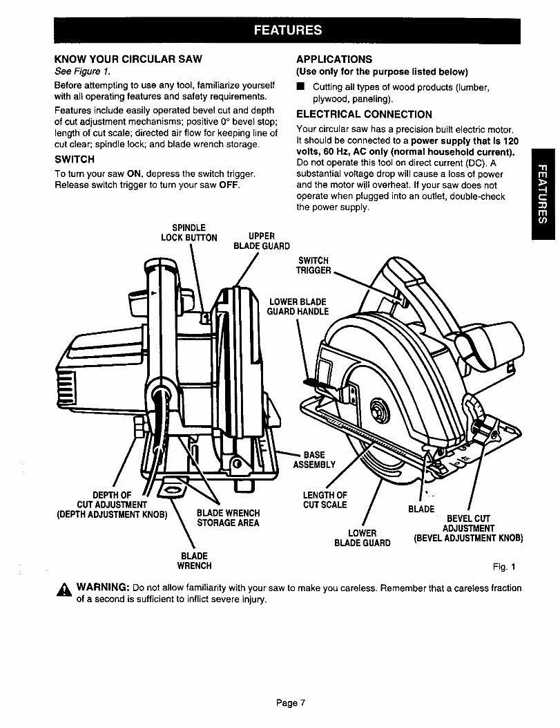
KNOWYOURCIRCULARSAWSee Figure 1.
Before attempting to use any tool, familiarize yourselfwith all operating features and safety requirements.
Features include easily operated bevel cut and depthof cut adjustment mechanisms; positive 0° bevel stop;length of cut scale; directed air flow for keeping line ofcut clear; spindle lock; and blade wrench storage.
SWITCH
To turn your saw ON, depress the switch trigger.Release switch trigger to turn your saw OFF.
SPINDLELOCKBuI"rON UPPER
BLADEGUARD
APPLICATIONS
(Use only for the purpose listed below)
• Cutting all types of wood products (lumber,plywood, paneling).
ELECTRICAL CONNECTION
Your circular saw has a precision built electric motor.It should be connected to a power supply that is 120volts, 60 Hz, AC only (normal household current).Do not operate this tool on direct current (DC). Asubstantial voltage drop will cause a loss of powerand the motor wUIoverheat, If your saw does notoperate when plugged into an outlet, double-checkthe power supply.
SWITCH
LOWERBLADEGUARDHANDLE
BASEASSEMBLY
DEPTHOFCUTADJUSTMENT
(DEPTHADJUSTMENTKNOB) BLADEWRENCHSTORAGEAREA
LENGTHOFCUT SCALE BLADE
BEVELCUT
LOWER ADJUSTMENTBLADEGUARD (BEVELADJUSTMENTKNOB)
BLADEWRENCH Fig. 1
,_ WARNING: Do not allow familiarity with your saw to make you careless. Remember that a careless fractionof a second is sufficient to inflict severe injury.
Page 7

_1, WARNING: Your saw should never beconnected to power supply when you areassembling parts, making adjustments,assembling or removing blades, cleaning, orwhen not in use. Disconnecting your saw willprevent accidental starting that could causeserious personal injury.
WARNING: A 7-1/4 in. blade is the maximumblade capacity of your saw. Never use a bladethat is too thick to allow outer blade washer to
engage with the flat on the spindle. Larger bladeswilt come in contact with the blade guards, whilethicker blades will prevent blade screw fromsecuring blade on spindle. Either of thesesituations could result in a serious accident.
TO ASSEMBLE OR REMOVE BLADE
• Unplug your saw.
_, WARNING: Failure to unplug your saw couldresult in accidental starting causing possibleserious personal injury.
TO ASSEMBLE BLADE:
• Remove blade wrench from storage area. See
Figure 1.
• Remove blade screw, spring washer and outerblade washer ("D" washer). See Figure 2.
SPINDLELOWERBLADE
GUARDHANDLE
BLADEOUTERBLADE
WASHER("D"WASHER)
BLADESCREW
• Fit saw blade inside lower blade guard and ontospindle. NOTE: The saw teeth point upward at thefront of saw as shown in figure 2.
• Replace "D" washer and spring washer.NOTE: "Cupped" side of spring washer goesagainst "D" washer. See Figure 3.
OUTERBLADEWASHER("D" WASHER)
CUPPEDSIDEOF OUTSIDEOFSPRINGWASHER SPRINGWASHER Fig. 3
• Depress spindle lock button, then replace bladescrew. Tighten blade screw securely.
NOTE: Turn blade screw clockwise to tighten.
• Return blade wrench to storage area.NOTE: Always place angled portion of bladewrench up as shown in figure 1.
REMEMBER: Never use a blade that is too thick
to allow the "D" washer to engage with the flaton the spindle.
TO REMOVE BLADE:
• Remove blade wrench from storage area. See
Figure 1.
• Position your saw as shown in figure 4, depressspindle lock button, and remove blade screw.NOTE: Turn blade screw counterclockwise to
remove.
• Remove spring washer and outer blade washer("D" washer). See Figure 2.NOTE: Blade can be removed at this point.
SPINDLELOCKBUTrON
INNERFLANGE
BUSHINGWASHER Fig. 2
NOTE: Turn blade screw countemlockwise to remove.
• Wipe a drop of oil onto inner flange bushing andouter blade washer ("D" washer) where theycontact blade.
_k, WARNING: If inner flange bushing has beenremoved, replace it before placing blade onspindle. Failure to do so could cause an accidentsince blade will not tighten properly.
Page 8
BLADEWRENCH
BLADESCREW
Fig. 4
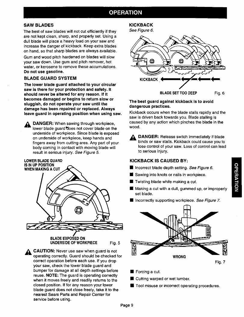
SAW BLADES
The best of saw blades will not cut efficiently if theyare not kept clean, sharp, and properly set. Using adull blade will place a heavy load on your saw andincrease the danger of kickback. Keep extra bladeson hand, so that sharp blades are always available.
Gum and wood pitch hardened on blades will slowyour saw down. Use gum and pitch remover, hotwater, or kerosene to remove these accumulations.Do not use gasoline.
BLADE GUARD SYSTEM
The lower blade guard attached to your circularsaw is there for your protection and safety. Itshould never be altered for any reason. If itbecomes damaged or begins to return slow orsluggish, do not operate your saw until thedamage has been repaired or replaced. Alwaysleave guard in operating position when using saw.
_IL DANGER: When sawing through workpiece,lower blade guard_oes not cover blade on theunderside of workpiece. Since blade is exposedon underside of workpiece, keep hands andfingers away from cutting area. Any part of yourbody coming in contact with moving blade willresult in serious injury. See Figure 5.
LOWERBLADEGUARDIS IN UP POSITIONWHENMAKINGA CUT
KICKBACK
See Figure 6.
KICKBACK '_mlm_KF'_E_
BLADESET TOODEEP Fig. 6
The best guard against kickback is to avoiddangerous practices.
Kickback occurs when the blade stalls rapidly and thesaw is driven back towards you. Blade stalling iscaused by any action which pinches the blade in thewood.
DANGER: Release switch immediately if bladebinds or saw stalls. Kickback could cause you tolose control of your saw. Loss of control can leadto serious injury.
KICKBACK IS CAUSED BY:
• Incorrect blade depth setting. See Figure 6.
• Sawing into knots or nails in workpiece.
• Twisting blade while making a cut.
• Making a cut with a dull, gummed up, or improperlyset blade.
• Incorrectly supporting workpiece. See Figure 7.
BLADEEXPOSEDONUNDERSIDEOF WORKPIECE Fig. 5
,_ CAUTION: Never use saw when guard is notoperating correctly. Guard should be checked forcorrect operation before each use. If you dropyour saw, check the lower blade guard andbumper for damage at all depth settings beforereuse. NOTE: The guard is operating correctlywhen it moves freely and readily returns to theclosed position. If for any reason your lowerblade guard does not close freely, take it to thenearest Sears Parts and Repair Center forservice before using.
WRONG
Fig. 7
• Forcing a cut.
• Cutting warped or wet lumber.
• Tool misuse or incorrect operating procedures.
Page 9

TO LESSEN THE CHANCE OF KICKBACK:
• Always keep the correct blade depth setting - thecorrect blade depth setting for all cuts should notexceed 1/4 inch below the material to be cut. See
Figure 8.
CORRECTBLADEDEPTHSETTING-BLADEEXPOSED1/4 in, OR
LESSON UNDERSIDEOF WORKPIECE Fig. 8
• Inspect the workpiece for knots or nails beforebeginning a cut. Never saw into a knot or nail.
• Make straight cuts. Always use a straight edge
guide when rip cutting. This helps prevent twistingthe blade in the cut.
• Always use clean, sharp and properly set blades.Never make cuts with dull blades.
• To avoid pinching the blade, support the workpieceproperly before beginning a cut. The right andwrong ways to support large pieces of workpieceare shown in figures 7 and 9.
• When making a cut use steady, even pressure.Never force cuts.
• Do not cut warped or wet lumber.
• Always hold your saw firmly with both hands andkeep your body in a balanced position so as toresist the forces of kickback should it occur.
When using your saw, always stay alert andexercise control. Do not remove your saw fromworkpiece while the blade is moving.
DEPTH OF, CUT ADJUSTMENT
Always keep correct blade depth setting. The correctblade depth setting for all cuts should not exceed 1/4inch below the material to be cut. More blade depthwill increase the chance of kickback and cause the cut
to be rough.
TO ADJUST BLADE DEPTH
• Unplug your saw.
_IL WARNING: Failure to unplug your saw couldresult in accidental starting causing possibleserious personal injury,
• Loosen depth adjustment knob. See Figure 10.
RIGHT Fig. 9
DEPTHADJUSTMENT
BASE KNOB
ASSEMBLY Fig. 1O
• Hold base flat against the workpiece and raise orlower saw until the required depth is reached.
• Tighten depth adjustment knob securely.
Page10

STARTING A CUT
Know the right way to use your saw.See Figure 11.
TO HELP MAINTAIN CONTROL:
• Always support your workpiece near the cut.
• Support your workpiece so the cut will be on yourright.
• Clamp your workpiece so it will not move duringthe cut.
Place your workpiece with its good side down. NOTE:The good side is the side on which appearance isimportant.
Before beginning a cut, draw a guideline along thedesired line of cut. Then place front edge of base onthat part of your workpiece that is solidily supported.See Figure 11.
Never place your saw on that part of theworkpiece that will fall off when the cut is made.See Figure 13.
RIGHT Fig. 11
Never use your saw as shown in figure 12.
WRONG Fig. 12
Never place your hand on the workpiece behindyour saw while making a cut.
,_, WARNING: To make sawing easier and safer,always maintain proper control of your saw. Lossof control of your saw could cause an accidentresulting in possible serious injury.
WRONG Fig. 13
Keep the cord away from cutting area. Always placethe cord to prevent it from hanging up on theworkpiece while making a cut.
A DANGER: If the cord hangs up on theworkpiece during a cut, release the switch triggerimmediately. Unplug your saw and reposition thecord to prevent it from hanging up again.
A DANGER: Using your saw with a damaged cordcould result in serious injury or death. If the cordhas been damaged, have it replaced beforeusing your saw again.
Page 11

Holdyoursawfirmly withbothhands.See Figure14.
TOPVIEWOF SAW
FRONT[7OF SAW i_ i
BLADEGUIDENOTCH
ALIGNOUTERBLADEGUIDENOTCHONSAWBASEWITHLINEOF CUTAS SHOWN GUIDELINEWHENMAKINGCROSSCUTS ORRIPCUTS Fig. 15
RIGHT Fig, 14
Squeeze the switct'_.trigger to start your saw. Alwayslet the blade reach full speed, then guide your sawinto the workpiece.
WARNING: The blade coming in contact withthe workpiece before it reaches full speed couldcause your saw to "kickback" towards youresulting in serious injury.
When making a cut use steady, even pressure.Forcing causes rough cuts, could shorten the life ofyour saw and could cause "kickback."REMEMBER:When sawing through work, the lower blade guarddoes not cover the blade, exposing it on theunderside of work. Keep your hands and fingersaway from cutting area. Any part of your bodycoming in contact with the moving blade willresult In serious injury.
After you complete your cut release the trigger andallow the blade to come to a complete stop. Do notremove your saw from workpiece while the bladeis moving.
Since blade thicknesses vary, always make a trial cutin scrap material along a guideline to determine howmuch, if any, the guideline must be offset to producean accurate cut. NOTE: The distance from the line ofcut to the guideline is the amount you should offsetthe guideline.
OPTIONAL EDGE GUIDE (RIP GUIDE)
Use a rip guide when making rip cuts up to five incheswide. It helps prevent the blade from twisting in a cut.The blade twisting in a cut can cause kickback. A ripguide is available at your Sears Catalog Order orRetail Store.
TO ASSEMBLE RIP GUIDE
• Unplug your saw,
_, WARNING: Failure to unplug your saw couldresult in accidental starting causing possibleserious personal injury.
• 4
• Place rip guide through holes in saw base asshown in figure 16.
_, CAUTION: When lifting your saw from theworkpiece, the blade is exposed on theunderside of your saw until the lower blade guardcloses. Make sure lower guard is closed beforesetting your saw down on work surface.
TO CROSS CUT OR RIP CUT
When making a cross cut or rip cut, align your line ofcut with the outer blade guide notch on the saw baseas shown in figure 15.
EDGEGUIDE(RIPGUIDE)
PLACERIPGUIDETHRUHOLES
Fig. 16
Page 12

• Adjust rip guide to the length needed for the cut.
• Tighten edge guide screw securely.
When using a rip guide, position the face of the ripguide firmly against the edge of workpiece. Thismakes for a true cut without pinching the blade. Theguiding edge of workpiece must be straight for yourcut to be straight. Use caution to prevent the bladefrom binding in the cut.
TO BEVEL CUT
The angle of cut of your saw may be adjusted to anydesired setting between zero and 51.5 °. NOTE: Whenmaking cuts at 51.5 ° blade should be set at full depthof cut, with edge guide screw removed.
When making 45 ° bevel cuts, there is a notch in thesaw base to help you line up the blade with the line ofcut. See Figure 17.
: BEVEL
SCALE
GUIDE..... BEVELNUm_M ADJUSTMENT
_GUIDELINE KNOB
ALIGNINNERBLADEGUIDENOTCHON SAWBASEWITHLINEOF CUT AS SHOWNWHENMAKING45° BEVELCUTS Fig. 17
Align your line of cut with the inner blade guide notchon the saw base when making 45 ° bevel cuts.
Since blade thicknesses vary and different anglesrequire different settings, always make a trial cutin scrap material along a guideline to determinehow much you should offset the guideline on theboard to be cut.
When making a bevel cut hold your saw firmly withboth hands as shown in figure 18.
\
LOWERBLADEGUARD
Fig. 18
Rest the front edge of the base on the workpiece.Squeeze the switch trigger to start your saw. Alwayslet the blade reach full speed, then guide your sawinto the workpiece.
,_ WARNING: The blade coming in contact withthe workpiece before it reaches full speed couldcause saw to "kickback" toward you resulting inserious injury.
After you complete your cut release the trigger andallow the blade to come to a complete stop. After theblade has stopped, lift your saw from the workpiece.
TO ADJUST BEVEL SETTING
• Unplug your saw.
_IL WARNING: Failure to unplug your saw couldresult in accidental starting causing possibleserious personal injury.
• Loosen bevel adjustment knob. See Figure 17.
• Raise motor housing end of saw until you reachdesired angle setting on bevel scale. See Figure17.
• Tighten bevel adjustment knob securely.
,_ WARNING: Attempting bevel cut without knobsecurely tightened can result in serious injury.
Page13
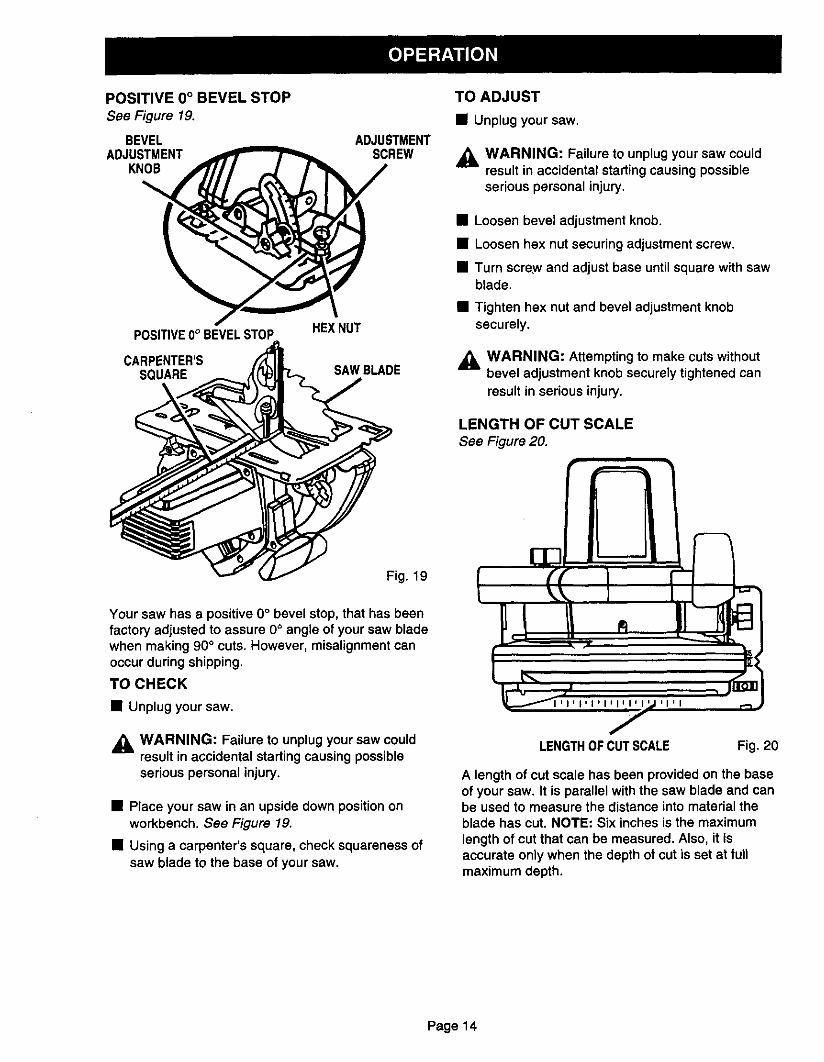
POSITIVE 0° BEVEL STOP
See Figure 19.
BEVELADJUSTMENT
KNOB
POSITIVE0°BEVELSTOP
CARPENTER'SSQUARE
ADJUSTMENTSCREW
HEXNUT
SAWBLADE
TO ADJUST
• Unplugyoursaw.
,_ WARNING: Failure to unplug your saw couldresult in accidental starting causing possibleserious personal injury.
• Loosen bevel adjustment knob.
• Loosen hex nut securing adjustment screw.
• Turn screw and adjust base untilsquare with sawblade.
• Tighten hex nut and bevel adjustment knobsecurely.
,_ WARNING: Attempting to make cuts withoutbevel adjustment knob securely tightened can
result in serious injury.
LENGTH OF CUT SCALE
See Figure 20.
Fig. 19
Your saw has a positive O° bevel stop, that has beenfactory adjusted to assure 0° angle of your saw bladewhen making 90 ° cuts. However, misalignment canoccur during shipping.
TO CHECK
• Unplug your saw.
_IL WARNING: Failure to unplug your saw couldresult in accidental starting causing possibleserious personal injury.
• Place your saw in an upside down position onworkbench. See Figure 19.
• Using a carpenter's square, check squareness ofsaw blade to the base of your saw.
LENGTHOF CUTSCALE Fig. 20
A length of cut scale has been provided on the baseof your saw. It is parallel with the sew blade and canbe used to measure the distance into material theblade has cut. NOTE: Six inches is the maximumlength of cut that can be measured. Also, it isaccurate only when the depth of cut is set at funmaximum depth.
Page 14

TO POCKET CUT
See Figure 21.
,_ WARNING: Always adjust bevel setting to zerobefore making a pocket cut. Attempting a pocketcut at any other setting can result in loss ofcontrol of your saw possibly causing serious
injury.
Adjust the bevel setting to zero, set blade to correctblade depth setting, and swing the lower blade guardup using the lower blade guard handle.
Always raise the lower blade guard with thehandle to avoid serious Injury.
While holding lower blade guard by the handle, firmlyrest the front of the base flat against the workpiecewith the rear of the handle raised so the blade doesnot touch the workpiece. See Figure 21.
LOWERBLADtEGUARD
Squeeze the switch trigger to start your saw. Alwayslet the blade reach full speed then slowly lowerblade Into the workplece until base Is flat againstworkplece.
After you complete your cut release the trigger andallow the blade to come to a complete stop. After theblade has stopped, remove it from the workpiece.Comers may then be cleared out with a hand saw orsabre saw.
,_ WARNING: Never tie the lower blade guard in araised position. Leaving the blade exposed couldlead to serious injury.
POCKETCUT
LOWERBLADEGUARDHANDLE Fig. 21
Page15

Page16

,_ WARNING: When servicing, use only identicalCraftsman replacement parts. Use of any otherpart may create a hazard or cause productdamage.
GENERAL
Only the parts shown on parts list, page nineteen, areintended to be repaired or replaced by the customer.All other parts represent an important part of thedouble insulation system and should be serviced onlyby a qualified Sears service technician.
Avoid using solvents when cleaning plastic parts.Most plastics are susceptible to damage from varioustypes of commercial solvents and may be damagedby their use. Use clean cloths to remove dirt, carbondust, etc.
,_ WARNING: Do not at any time let brake fluids,gasoline, petroleum-based products, penetratingoils, etc. come in contact with plastic parts. Theycontain chemicals,that can damage, weaken ordestroy plastic.
It has been found that electric tools are subject toaccelerated wear and possible premature failure whenthey are used on fiberglass boats, sports cars,wallboard, spackling compounds, or plaster. Thechips and grindings from these materials are highlyabrasive to electric tool parts such as bearings,brushes, commutators, etc. Consequently, it is notrecommended that this tool be used for extendedwork on any fiberglass material, wallboard, spacklingcompounds, or plaster. During any use on thesematerials it is extremely important that the tool iscleaned frequently by blowing with an air jet.
_I, WARNING: Always wear safety goggles orsafety glasses with side shields during power tooloperation or when blowing dust. If operation isdusty, also wear a dust mask.
LUBRICATION
All of the bearings in this tool are lubricated with asufficient amount of high grade lubricant for the life ofthe unit under normal operating conditions. Therefore,no further lubrication is required.
EXTENSION CORDS
The use of any extension cord will cause some loss ofpower. To keep the loss to a minimum and to preventtool overheating, use an extension cord that is heavyenough to carry the current the tool will draw.
A wire gage size (A.W.G.) of at least 12 isrecommended for an extension cord 50 feet or less inlength. When working outdoors, use an extensioncord that is suitable for outdoor use. The cord's jacketwill be marked WA.
,_ CAUTION: Keep extension cords away from thecutting area and position the cord so that it willnot get caught on lumber, tools, etc., duringcutting operation.
_. WARNING: Check extension cords before eachuse. If damaged replace immediately. Never usetool with a damaged cord since touching thedamaged area could cause electrical shockresulting in serious injury.
Extension cords suitable for use with your circular saware available at your nearest Sears Retail Store.
Page 17
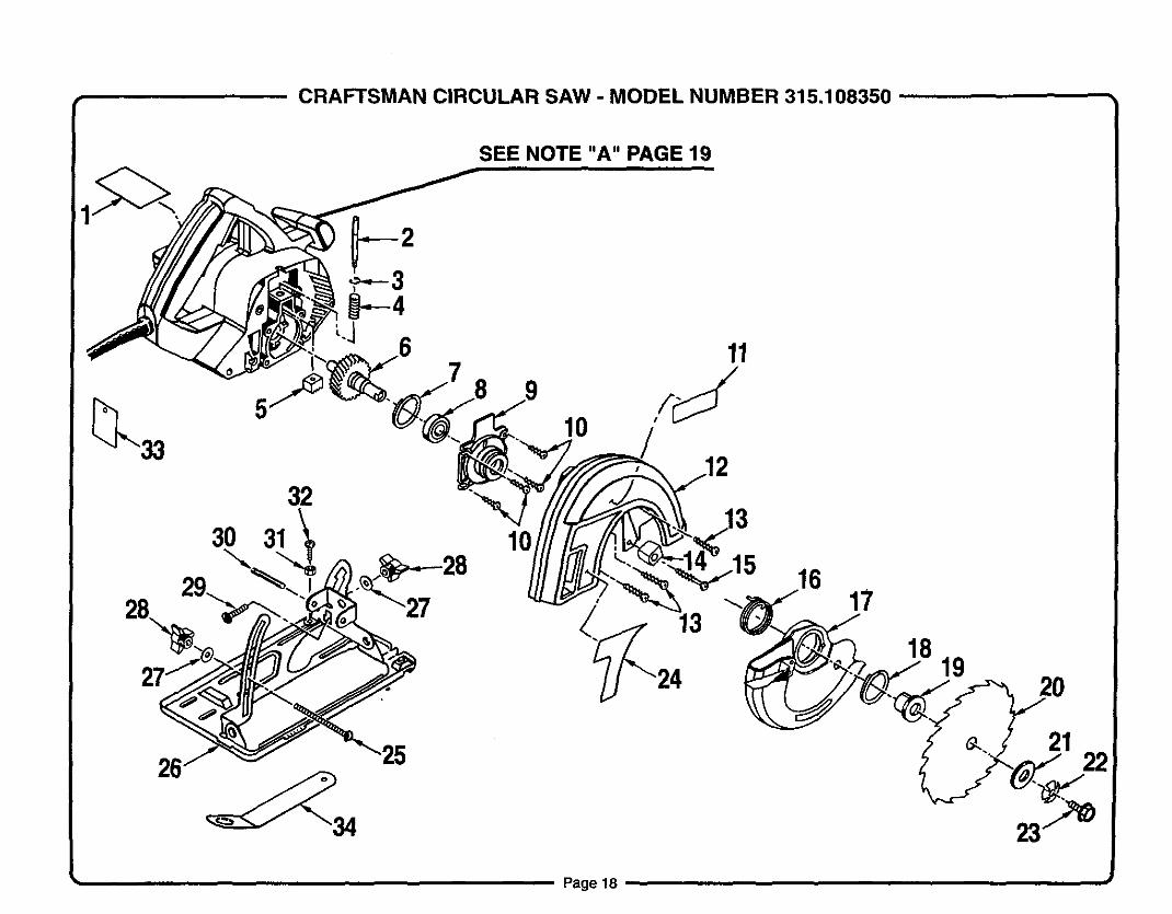
• CRAFTSMAN CIRCULAR SAW - MODEL NUMBER 315.108350 .....
SEE NOTE "A" PAGE 19
26
30
32
31 10
10
11
12
1617
1819
2o
_.. 21 22
Page18 ,,

CRAFTSMAN CIRCULAR SAW - MODEL NUMBER 315.108350
I he model number will be found on a plate attached to the motor housing. Always mention the model number in all correspondence regarding your |CIRCULAR SAW or when ordering repair parts. ISEE BACK PAGE FOR PARTS ORDERING INSTRUCTIONS
PARTS LIST
Key PartNo. Number
1 974544-001
2 968907-002
3 623111-002
4 621342-000
5 968906-001
6 969858-002
7 617096-002
8 615972-004
9 968091-002
10 974999-001
11 975205-001
12 968442-002
13 968702-011
14 974900-001
15 989592-001
16 967952-001
17 974771-001
18 718602-804
Description Quan.
Data Plate ...................................................... 1
Gear Rack Shaft ............................................. 1
Retaining Ring ................................................ 1
Spring ............................................................. 1Gear Rack ...................................................... 1
Gear and Spindle ........................................... 1
Retaining Ring ................................................ 1
Ball Bearing (NTN#6003LLBC3/1 E) ............... 1
Lower Blade Guard Support ........................... 1
* Screw (#10-16 x 3/4 in. Pan Hd.) ................... 4
Logo Plate ...................................................... 1Fixed Blade Guard ......................................... 1
* Screw (#8-16 x 3/4 in. Pan Hd.) ..................... 3
Bumper .......................................................... 1
* Screw (#8-10 x 1-1/8 in. Fil. Hd.) .................... 1
Torsion Spring ................................................ 1
Lower Blade Guard Assembly ........................ 1
Retaining Ring ................................................ 1
Key Ptart
No. Number Description
19 967887-003
20 ***
21 998463-001
22 623547-002
23 612999-001
24 975145-001
25 621433-018
26 974802-001
27 931744-059
28 999529-002
29 621433-001
30 941401-815
31 706404-007
32 614658-010
33 990147-001
34 974716-001
972000-323
Quan.
Inner Flange Bushing ..................................... 1Saw Blade 7-1/4 in. for 5/8 in. Arbor .............. 1
Outer Blade Washer ....................................... 1
Spring Washer ............................................... 1Blade Screw ................................................... 1
Logo Plate ...................................................... 1
Carriage Bolt (1/4-20 x 3-3/4 in.) .................... 1
Base Assembly .............................................. 1Washer ........................................................... 2
Knob ............................................................... 2
Carriage Bolt (1/4-20 x 5/8 in.)**STD532507 ................................................. 1
Roll Pin ........................................................... 1
Hex Nut (#8-32) **STD541008 ...................... 1
* Screw (#8:32 x 5/8 in. Pan Hd.) ..................... 1
Warning Tag .................................................. 1Wrench ........................................................... 1
Ownecs Manual
NOTE: "A"- The assembly shown represents an important part of the Double Insulated System. To avoid the possibility of alteration or damageto the system, service should be performed by your nearest Sears Repair Center. Contact your nearest Sears Retail Store forService Center information.
* Standard Hardware item -- May Be Purchased Locally** Available From Div.98 -- Source 980.00
*** Complete Assortment Available At Your Nearest Sears Retail Storelk-']lll L--'_q_d_.m
Page 19

For repair of major brand appliances in your own home...no matter who made it, no matter who sold it!
1-800-4-MY-HOME sMAnytime, day or night
(1-800-469-4663)
www.sears.com
To bring in products such as vacuums, lawn equipment and electronicsfor repair, call for the location of your nearest Sears Parts & Repair Center.
1-800-488-1222 Anytime, day or night
www.sears.com
For the replacement parts, accessories and owner's manualsthat you need to do-it-yourself, call Sears PartsDirect sM!
1-800-366-PART 6 a.m.- 11 p.m. CST,
(1-800-366-7278) 7 days a week
www.sears.com/partsdirect
To purchase or inquire about a Sears Service Agreement:
1-800-827-66557 a.m. - 5 p,m. CST, Mon. - Sat.
Para pedir servicio de reparaci6n a domicilio,y para ordenar piezas con entrega a domicilio:
1-888-SU-HOGAR SM
(1-888-784-6427)
Au Canada pour service en fran_:ais:1-877-LE-FOYERS"
(1-877-533-6937)
® Registered Trademark / TM Trademark of Sears, Roebuck and Co.
TM® Sears, Roebuck and Co. ® MarCa Registrada / Marca de F_brlCa de Sears, Roebuck and Co.


![nEXTEC - Sears Parts Direct · bL'_:]_ _o__o_ Warranty Page 2 Safety Symbols Pages 3-4 Safety Instructions Pages 5-11 Description Pages 11-12 Assembly Page 13 Operation Pages 14-20](https://static.fdocuments.us/doc/165x107/5f8754623366fb4ac70aa86f/nextec-sears-parts-direct-bl-oo-warranty-page-2-safety-symbols-pages.jpg)