Sears - Appliance Parts · Sears GAS.FIRED FORCED AIR WALL FURNACE @.Installation.Operation •...
29
Sears GAS.FIRED FORCED AIR WALL FURNACE @ .Installation .Operation • Repair Parts FOR YOUR SAFETY FOR YOUR SAFETY Do not store or use gasoline or other flammable vapors and liquids in the vicinity of this or any other appliance. If you smell gas: 1. Open windows. 2. Don't touch electrical switches. 3. Extinguish any open flame. 4. Immediately call your gas supplier. Sears, Roebuck and Co., Chicago, II. 60684 U.S.A. PRINTED IN U.S.A.
Transcript of Sears - Appliance Parts · Sears GAS.FIRED FORCED AIR WALL FURNACE @.Installation.Operation •...

Sears GAS.FIRED
FORCED AIR
WALL FURNACE
@.Installation
.Operation
• Repair Parts
FOR YOUR SAFETY FOR YOUR SAFETY
Do not store or use gasoline or
other flammable vapors and liquids inthe vicinity of this or any otherappliance.
If you smell gas:1. Open windows.2. Don't touch electrical switches.
3. Extinguish any open flame.4. Immediately call your gas supplier.
Sears, Roebuck and Co., Chicago, II. 60684 U.S.A.PRINTED IN U.S.A.

ContentsIntroduction ................................... 2
Sears Warranty ................................ 2Sears Installation Policy ........................ 2Sears Installation Warranty ..................... 2
safety Rules ................................. 2-3Basic Tools Needed ............................ 3Basic Materials ................................ 3
Optional Accessories ........................... 4Furnace Data .................................. 4
Unpack Your Furnace .......................... 4Installation Steps .............................. 5
Locating Furnace .............................. 5Combustion Air .............................. ; .5
_'-*_l I IIIIIIIIIIIIIIIIIIIII IIIIUIIIIIIIIIIIII
,ntroduction
Installation
Surface Mount Installation.................. 6-9
Recessed Installation.................. ,...9-13
Connecting Gas Line .......................... 13
ElectricalWiring .............................. 14Thermostat Installation ........................ 14
Checks and Adjustment._.................... 14,15
Lighting ..................................... 16How To Use Your Furnace ...................... 16
How To Care For Your Furnace."................. 17
SERVICE HINTS ............................... 17
Wiring Diagram .............................. 18
Repair Parts............................... 19-27
............. IIIIIIIIIIIIIIIIIIIII I'IIIIIIIIIIIIIIIIIIIII I
Please read our instructions before you install and use your furnace. This will help you obtain the full value from
this furnace. It will also help you avoid any needless service costs, if the problem is something we cannot controland cann°tc°ver in our Warranty.
i I _II l I l IIB III I Iml I Im Mil lllii I l I Hi lliI I l I l I _III II lie I l I l I I i I I _
- FULL ONE YEAR WARRANTY ON SEARS WALL FURNACE JJFor one year from the date of purchase, when thisfurnace isinstalledand maintained in
accordance -withour instructions,Sears willrepairdefectsin material or workmanship in
the furnace, free of charge, a
LIMITED WARRANTY ON HEAT EXCHANGER II
! After one year and through len years from the date of purchase, Sears will furnish a =,rep]acement Heat Exchanger, if the Heat Exchanger in the furnace is defective. You pay for .1
warranty gives you specific legal rights, you may vary IThis and also have other rights which from state
! ,o,,ote -I.Sears, Roebuck and Co.
II BSC 41-3, Sears Tower. Chicago, Illinois 60684 I1_lil I miD I i I aim I Hi I i ! a I Im I Nil i am III It I i III Ill I l I imami I I i ! mam H am I am l:ll'iiil _
To function properly, your furnace must be installed correctly. You must know how tO Us_the tools:ilOlDd;eq_ipmentand understand electrical wiring and potential hazards. If there is any doubt we ask thaf;_ou contact your Sears
Salesman. He will arrange for professional installation.I ill I ill i I I I I I m IJI l i I IJ I I l Ill I l ! I ! n 11m ! Ill I ImI I IJm I I I Ill IIE I I I I i i
n SEARSlNSTA"ATIONPOUCY i SEARSINSTA"ATIONWARRANTYnALl installation labor arranged by Sears shall be "_. In addition to any warranty extended to you on the ,,,
I performed in a neat, workmanlike manner in I Sears merchandise involved, which warranty be-I,= accordance withgenerallyacceptedtrade practices. _ comes effective the date the merchandise is =J Further, ai[ installations shall comply with all local I installed, should the workmanship of any Sears I.= laws, codes, regulations, and ordinances, The " arranged installation prove faulty within one year, _"! customersha.alsobeprotecteddu.nginsta,,ation,I Sears uponooticefromyou.causesuchfaultstoI!m
by insurance relating to Property Damage, Work- : be corrected at no additional cost to you.
i men's Compensation and Public Liability. _llIIIIIIIIiIIIIIIlllllIII IIilIIIIIIIlilIIIIIIIlilI
If[fill II'IIIIIIIIIIIIIIIII
Safety Rules1. Read these rules and the instructions carefully.
Failure to follow these rules and instructionscould cause a malfunction of the furnace. This
could result in death, serious bodily injury,and!or property damage.
2. This furnace must be installed in accordance2
with local codes and ordinances or, in their'absence with the National Fuel Gas Code,ANSI Z223.I-1974.
3. Do not install this furnace in an alcove.
4. Do not install this furnace in a mobile home,trailer or recreational vehicle.

5. Maintainall clearancesspecifiedon page5,LocatingTheFurnace.
6. Be sure furnaceis equippedfor type of gas(Naturalor LP)to be used.Checkthe ratingplate.
7. Gassupplypressuretothefurnacecontrolvalvemust be at least5 incheswater columnforNaturalgas and 11 inches,watercolumnforLPgas.It mustnot bemorethan14inches,
8. Thefurnacemustbeventedto the outdoorssothat harmfulgaseswill not collectinsidethebuilding.Followthe venting instructionsforyour type installation exactly. Use only the typeand size of vent pipe and fittings specified.
9. Be sure to provide enough combustion andventilation air. See page 5. The flow of this airto the furnace must not be blocked.
10. Never test for gas leaks with an open flame. Use
soap suds to check all gas connections. This willavoid the possibility of fire or explosion.
11. Before servicing, allow furnace to cool. Alwaysshut off electricity and gas to furnace when
IIIII I
Basic Tools Needed
12.
13.
14.
15.
16.
working on it. This will prevent any electricalshocks or burns.
Due to high temperatures, the furnace shouldbe located out of traffic and away from furnitureand draperies.
Children and adults should be alerted to the
hazards of high surface temperature and shouldbe kept away to avoiTJ"!_urns or clothing ignition.
Young children should be carefully supervisedwhen they are in the same room with thefurnace.
Do not place clothing or other flammablematerial on or near furnace.
Installation and repair should be done by aqualified service person. The furnace should be!nspected before use and at least annually by aprofessional service person. More frequentcleaning may be required due to excessive lintfrom carpeting, bedding material, etc. it isi-mperative that control compartments, burners,and circgiafing a!r passage ways of the furnacebe kept clean.
IIIIIIIIIl_llllllllUII_
Hand drill or properly grounded electric drillExpansion bit 7/8" to 1-5/8"3/32" drill bit (metal)6 ft. folding rule or tapeScrewdriversPliers (wire cutting)Hammer
I II]1 III I I I
Basic Materials
Tin Snips8" adjustable wrench12" adjustable wrench
Key hole sawHack'saw
2 - 10" or 12" pipe wrenchesGloves
IIIIIIIIIIIIIIIIIIIIIIII II III
Black iron or steel pipe and fittings to makeconnections from gas meter to furnace.
Pipe joint compound
Electrical wiring supplies as needed (See page 14).
Vent Shield Kit, Sears Stock No. 42-7311, if furnace isto be mounted on a wall surface (not recessed inwall).
Sears Stock No. 42-99767 gas vent kit for verticalventing or Sears Horizontal Vent Kit, Stock No.42-7369 for Horizontal venting.
Extra lengths of round, double wall vent pipe may beneeded. You must use 4 inch pipe for vertical ventingand 5 inch pipe for horizontal venting, it must beType B-1 vent (listed by Underwriters Laboratoriesfor Type B installation at 1 inch clearance .tocombustible materials).
I
Helpful InformationThe following booklets will help you in makingthe installation.
Available at Sears from the Plumbing, Heating orElectrical Departments at nominal cost:
Do It Yourself Plumbing Handbook
Basic Wiring
American National Standard Z223.1-1974 "NationalFuel Gas Code".
Obtain from- American National Standards
Institute, Inc., 1430 Broadway, New York, N.Y.10018,
3

Optional Accessories1. Tall Register Kit, Sears Stock No. 42-7312, For use
when replacing a "Dual Wail" furnace. Tallregister covers existing walt opening.
2. Shot;r Rear Wall Register Kit, Sears Stock No.42-7313. For use when installing two-roomheating but not replacing "Dual Wall" furnace,
3. Vent Shield Kit, Sears Stock No. 42-7311. isrequired when mounting the furnace on the sur-face of the wall.
4. Horizontal Vent Kit, Sears stock No, 42-7369 is
required if furnace ;s to be vented horizontallyinto on existing chimney.
I . I IIIIIIIIIII I II IIIIIIIIIIIIIJ I I I IIIIIIIIIIIII IIIIIIIIIIIIIIIII II IIIII/11] IIIIIIIIII I IIIIIIIllll IIIIIIII
Furnace Data
MODELNUMBER
....867.736349
867.736389
INPUT**
TYPE RATING
GAS Btuh***
Nat. : 65,000L,P.* 65,000
MAIN BURNER ORIFICE
2 REQUIRED
DRILL DEC.
...... 36 .1o65"52 .0655"
PILOT ORIFICE
DECIMAL
.018"
.010"
*Liquefied Petroleum.
**For elevations above 2000 ft. reduce ratings 4% for each 1000 ft. above sea level.***Btuh = British Thermal Units per hour.
BE SURE YOUR FURNACE IS EQUIPPED FOR THE TYPE OF GAS TO BE USED, EITHER NATU_,AL OR L.P. GA,5. THECONNECTIONS FROM THE L.P. BULK STOlYAGE TANK TO THE FURNACE CAN ONLY BE MADE BY A LICENSEDL.P. DEALER.
I ...................................................... __..I " L -
Unpack Your FurnaceThe shipping carton contains the furnace and thefollowing items needed to install it.
1, Thermostat and wire -- packed inside lowercabinet door (Fig. 1).
2. Top trim piece and small parts bag -- taped toinside end of carton.
3. Vent support assembly -- in package taped toend of furnace.
Store these items where they cannot be lost ordamaged.
Grasp each side of the cabinet door. Pull forwardand upward to remove (Fig. 1).
BE SURE YOUR FURNACE IS EQUIPPED FOR THE TYPE
OF GAS TO BE USED, EITHER NATURAL OR L.P.CHECK THE RATING PLATE. IT IS ON THE PANEL JUSTABOVE THE GAS VALVE.
Remove the cabinet door knob screw. Reinstall the,knob on the outside.
Remove the two (2) screws holding the upper panel(Fig. 1). Remove the panel for access to fan,
Remove the shipping bracket and tape from the fanmotor. Untape and remove the spacers between themotor mount wires (Fig. 1).
t' [.</_L_-_ _ \ i !---=------': uPPeR
.- / / ! llUlli__ -_' SHIPPING BRACKET _ r
SHIPPING RUNNER
CABINET - -
SHIPPING
RUNNER _---,._._.
CABINET DOOR "
SELECTOt_SWITCH
KNOB
Reinstall the upper front panel, Stand the furnaceupright. Remove the runners (Fig. 1).
Place the selector switch knob (shipped in parts bag)on the shaft sticking through the front panel (Fig. t).
4

Installation StepsThe following steps ar.e all needed For properinstallation and safe operation of your wall furnace.If you have any doubts as to any requirements, checkwith local authorities.
I IIIIIIIIIIII II
Locating the FurnaceIIIIII
Obtain professional help where needed. The Checksand Adjustments on page 14 are vital to proper andsafe furnace operation. Be sure they are done.
I I II
This furnace can be:
1. installed between (Recessed Mount) 2"x4" wallstuds spaced on 16 inch centers, or
Attached to (Surface Mount) an inside or outsidewall.
A. You need Vent Shield Kit, Stock No. 42-7311
(sold separately) for surface mounting.
2. Installed to vent vertically, or horizontally into onexisting chimney.
A. To vent horizontal¥ use Horizontal Vent KitStock No. 42-7369 (sold separately). This kit
mmmlllml _mmemi emtmmmm(mlammlIn mliit tiimqaimammgpmaillmmm!
mm Iqm immli__mmnm
'mimmmImimmllm |
6" mman
MtN.E_J_]BETWEEN
will require five inch type B-I (round _doub)e
w,alt) vent pipe (sold separately) leadlngfrom it to the chimney.
B. To vent vertically, use type BW (oval doublewall) gas vent pipe and fittings. Sears gas ventkit, Stock No. 42-99767, may be used.
3. Installed with a rear wall register (optionalaccessory kit). If it is to be used, follow instruc-tions with the kit. Cut opening in rear wall forregister before mounting furnace in front wall.
Consider the following points before attempting toinstall the furnace.
1. Check the minimum spacing needs as shown inFig. 2. Do not place furnace closer than 7/8 inch
R
EITHERRIGHT ORLEFT SlOE
ANDWALL
I mlllllll _lit _
mulmmm_mmmmnmm!l Immllummmtgnnl|nPmm|iHH
FLOOR
+ f6" MIN,
t CEILING
to floor or floor covering.
2. Place the furnace near the center of the spaceto be heated for good_ air circulation. Do not put i_behind a door or draperies. Do not install it in acloset, alcove, hallway or other confined space.
3. After picking a location, inspect the wall, floor,attic and roof areas. Make sure there are no
I IIIIIIIIII l I_lIIIIIIIIIIIIIIIIIIIIIIIm I
Combustion Air
(
' i_J__7 tg"/WN., 4" RECOMMENIDEO
+
pipes, wiring, bracing, etc., that would interferewith furnace or vent installation. Move them or
pick a new location.
4. Be sure that gas piping and electrical wiring can
be brought to the' location. See sections on gaspiping and electrical wiring for your h/pe offurnace mounting.
I I IIIIIIIIIIIIIIIIIIIIIIJJJI I II I II I
WARNING
I E SURE TO PROVIDE ENOUGH FRESH AIR FORCOMBUSTION AND VENTILATION.
outside air must enter the house to replace that
used by the burner.
Homes usually have enough leakage around doorsand windows to provide all the air needed.
If the furnace is installed in on unusually tight.home(with well fitting =term window; and doors, weatherstripping, cracks caulked, etc.) fresh air must bebrought in from the outside through a permanentopening at least 13 square inches in free area.
Comply =with ANSI standard 7.223.1-1974 "The .National Fuel Gas Code", and with your local codesand ordinances, m
5

Surface Mount Installation(FOR RECESSED MOUNT INSTALLATION, TURN TO PAGE 9)
For ease of installation, servicing and cleaning,install the furnace at least four (4) inches above thefloor (Fig. 2).
FIND THE STUDS
Use a stud tocator or four 8 penny finishing nails.Repeatedly drive and remove a nail into the wall inthe area of the stud until it is located. Then find oneside. Leave the nail at this location. Drive another
nail just on the other side of the same stud. Theother stud should be about 16 inches from the one
found. Drive finishing nails on both sides of this stud.Draw centerline on walt for each stud (Fig. 3).
FLOOR LAYOUT
FLOOR jLINE
GAS _TPIPE I""
OPENING RICAL OPENINGi ,IlL
WALL LAYOUT
FLOOR
4
li
ii'1tIJItII
_-- TOP SUPPORT
BRACKET LINE
II[
14-3/B"
Ii
e=*
I_l
I'I
73"
GAS AND ELECTRICAL SUPPLYOPENINGS
Drill a 1Y=" hote in floor for gas line (Fig. 4).
The electrical supply opening must be at the lowerright of the furnace, either in the floor or wallbeneath the furnacebottom (Fig. 3 or 4).
Decide which location to use and drill a I inch hole.
Run the electrical supply and ground wires to theopening. Leave enough length to connect in thejunction box after the furnace is installed, Seesection "Electrical Wiring", page 14.
INSTALL FURNACE SUPPORTS
Use a surface mount vent shield kit, Sears Stock No.
42-7311. Obtain from your local Sears store.
Remove the support brackets from the kit. Centerand fasten the small support bracket to the wall fourinches from the floor {Fig. 3). Use four #10x11/2 flathead wood screws furnished.
For vertical venting, center and fasten the topsupport bracket to wall with the flange turned up 73inches above the bottom bracket as shown in Fig. 5.For horizontal venting fasten the bracket with theflange turned down. See page 8. Use four 8x11/_"round head wood screws furnished.
SURFACE MOUNT
BW VENT BASEPLATE
BOTTOM PLATE
INSULATION SEAL
FLUE
COLLAR
TOP
SUPPORT
BRACKET
MENDED
BOTTOMSUPPORT BRACKET
6

VERTICAL VENT INSTALLATION
Use a Type B-W gas vent installation kit, Sears StockNo. 42-99767 (Fig, 6).
VENT INSTALLATION
2 FEET
VENT TOP
COLLAR
4" IB-1
VENT PIPE
OVAL TO ROUND
ADAPTER
BW VENT
BASE PLATE
CUT CEILING OPENING
Cut a ceiling opening 14-3/8" wide by 3-5/8" deep,This must be directly above support brackets. Theback edge of the opening must be flush with thewall (Fig. 7),
INSTALL CEILING PLATE SPACERS
CEILING PLATE SPACERS
PLATE
HEADERS SPACERSCEILING JOISTS
PARALLEL TO
HOLE IN
CEILING
Two ceiling plate, spacers are in the B-W vent kit.They must be fastened along each tong edge of theceiling hole to hold the oval vent pipe in the center ofthe hole (Fig. 7).
If your ceiling joists run at right angles to the walland are in line with the studs, nail the plate spacersto the ]oists. Be sure they tine up with the long edgesof the holes.
If the joists run parallel to the wall, install 2"×6"headers between two joists as shown in Fig. 7. If thejoists and studs do not.line up, install headers asrequired to support the plate spacers.
INSTALL FURNACE VENT
Remove two screws in vent support assembly (Fig.8). Discard the vent support. Attach the bottomplate, ftue collar, seal, and base plate from B-W gasvent kit to the top support on wall (Fig. S).
VENT SUPPORT
SEAL
COLLAR
VENT
SUPPORT
DISCARD
BoI'rOM PLATE
II III IIIII IIIIII lie
Lower a 4 foot length of oval, double wall vent pipethrough the ceiling hole to the base plate. The firstlength of pipe must reach from the base plate to atleast 6 inches above the ceiling (Fig. 6). if it does not,
you must use a longer length. Force the vent pipeinto the base plate. Be sure the seal is in place. Lockthe pipe to the base plate with screws furnished inthe B-W gas vent kit.
7

SURFACE MOUNT INSTALLATION (CONTINUED)
install ovat to round adopter. Complefe the piping,extending it through the roof. Use 4" round, doublewall (Type B-l) vent pipe, roof flashing, storm collar,and vent top as shown in Fig. 6. The vent top must beat least 2 feet above the highest point of the roofwithin 10 feet, There must be at least 1 inch
clearance between the vent pipe and any combusti-ble material.
If an existing brick chimney is used, follow thedirections above for the section from the base platethrough the ceiling. Then you may adapt to a TypeB-1,4" round, double wall pipe for the horizontal runto the chimney. Connect into a chimney only inaccordance with local codes and ordinances.
HORIZONTAL VENT INSTALLATION
The furnace can be vented horizontally only by usingthe horizontal vent kit, Stock No. 42-7369.
lnstafl top support with flange facing down as shownin Fig. 9. Cut a 14-3/8 inch wide by 8l/2 inch hole infront wal! above top support. Make bottom edge ofhate even with top edge of top support.
•HOLE
IN
II,ACK
WALL
TOP
SUPPORT
Iii II iI I
i BOTTOMi
SUPPORT
II1II
I t
I n
III
HOLE IN
FRONT
WALL
Remove the round knockout from wall shield in thehorizontal vent kit. Insert the wall shield into the
81/2"x14-3/8" opening so that round hole faceschimney. Use hole in wall shield to mark opening tobe cut in back wall for vent pipe. If walt is less than3-7/8 inches, trim shield so front edge is flush withwail covering. Cut round hole. Nail wall shield tostuds (Fig. 10).
HORIZONTAL VENTING
BACK
WALL
VENT
SH_LD
TEE
NAIL
TO
Remove the plate, flue collar and insulation seatfrom the vent support assembly furnished with thefurnace (Fig. 8). Install these with the Tee to 'the topsupport as shown in Fig. 10. Discard vent support.
Complete the vent from the Tee to the chimney,using S" Type B-t vent pipe. The horizontal runshould slope upward 1/4" per foot of run. Keep atleast one inch clearance between the vent pipe andany combustibJe material.
Make sure that the end of the vent pipe does not gointo the chimney further than the inner surface. Sealit in place with furnace cement.
MOUNT FURNACE ON SUPPORTS
Hold the furnace at a sIight angle with top towardwall. Insert the flue in the openings in the topsupport and flue collar. Straighten the furnace bybringing it to rest onthe bottom support.
Install cabinet door and front panel.
8

INSTALL VENT SHIELD
The vent shield is 35-t/8 inches long. Measure fromtop of furnace to ceiling. Cut the vent shield to this
dimension less 1/8 inch. Be sure to cut from the top(end opposite flange) (Fig. 11).
Place vent shield on top of furnace and against thewall. Drill holes in the furnace top through holes invent shield. Fasten to furnace with sheet metalscrews. Screw sides to wall,
install wood trim moulding if desired, if 3/4 inchquarter round trim is used, trim 1/8 inch from bothside flanges before installing vent shield.
FLANGE
WOOD
TRIM
(NOT FURN|SHED!
IIIIIIIIIIIIIIIIII I II IIIIIIIIIIIIIIIIIIIIIII I I I llli IIIIIII
Recessed Mount Installation
For ease of installation, servicing and cleaning,install the furnace at Least four (4) inches above thefloor (Fig. 12).
FIND THE STUDS
Use a stud Iocator or four 8 penny finishing nails.Repeatedly drive and remove a nail into the wall inthe area of the stud until it is located. Then find oneside. Leave the nail at this location. Drive another
nail just on the other side of the same stud.
Inside edge of the other stud should be about 14-1/2inches from the one found. Drive finishing nail oninside edge of this stud.
CUT WALL OPENING
Lay out and cut a 14-3/8" by 74-1/2" opening asshown in Fig. 12.
WALL LAYOUT
I14-I/2"STUDS
/\
! • 74-I/2"
tIi| i 4_• " : L RECOMA_ENDtEOF J_.'iM.' H. iHJHJ'i , 11
Ii LL Ill :
9
\

RECESSED MOUNT INSTALLATION (CONTINUED)
FURNACE SUPPORT BLOCKS
Cut two (2) 3-1/8" high, 2 x 4 blocks, and nail to floorplate and studs (Fig. 13).
GAS AND ELECTRICSUPPLY OPENINGS
GAS LINE OPENING BOTTOM OFIN BACK WALL
FURNACE
2x4
SUPPORT _--__ _BLOCKS
ELECTRICAL
SUPPLY OPENING
IN FLOOR PLATE
OR WALL STUD
OR FLOOR
I" D4A.
CEILING PLATE SPACERS
, jGAS LINE
OPENING FINISHED
IN FLOOR FLOOR LINE
GAS AND ELECTRICAL SUPPLY OPENINGS
Decide whether the gas fine will come through lhefloor or back wall.
Drill a 1 ]/2" hole in ",vail or floor (Fig. t3).
The electrical supply opening must be at the lowerright of the furnace, either in the floor or studbeneath the furnace bottom (Fig. 13).
Decide which location to use and drill a 1 inch hole.
Run the electrical supply and ground wries to theopening. Leave enough length to connect in thejunction box after the furnace is installed. Seesection "Electrical Wiring", page 14.
VERTICAL VENT INSTALLATION
Use a Type B-W gas vent installation kit, Sears StockNo. 42-99767 (Fig. 17).
INSTALL CEILING PLATE SPACERS
Cut away the ceiling plate between the studs "where
the furnace is to be installed. Work from the top inthe attic.
If there is no access to the top, remove the wall
covering between the two wall studs, all the way tothe ceiling. Work through this opening.
Cut out the entire ceiling plate so the plate edges.will be even with the inner face of the 2" x 4" studs
(Fig. t4),
Nail the ceiling plate spacers (furnished with gasvent kit) across the cut out section of ceiling plate(Fig. 14). The spacer lugs are to center the oval ventpipe in the stud space.
INSTALL VENT SUPPORT
Measure up 73 inches from the top of the supportblock. Pl_ce a mark on each stud :_t this distance(Fig. 15).
VENT SUPPORT INSTALLATION
BASE PLATE
TOP OF
VENT SUPPORT
VENT SUPPORT
ASSEMBLY
SUPPORT
BLOCKS
I I
I 1
/BOTTOM OF WALL OPENING
10

Remove two screws from vent support assembly
(Fig. 16). Place Base plate (furnished with gas ventkit) on top of seal. Fasten base plate, seal, ftuecollar, vent support and bottom plate together with
screws (Fig. 15).
VENT SUPPORT
ASSEMBLY
SEAL
FLUE
COLLAR
VENT
SUPPORT
SO'frOM PLATE
Place the vent support between the studs with the
top even with marks on the studs (Fig. 15).
Drill pilot holes in the studs through the two holes ineach side of vent support.
Fasten vent support to the studs. Use four (4) #10 xV2" wood screws (furnished),
INSTALL FURNACE VENT
Lower a 4 foot length of oval, double wall vent pipethrough the ceiling hole to the base plate. The firstlength of pipe must reach from the base plate to atleast 6 inches above the ceiling (Fig. 17). If it doesnot, you must use a longer length. Force the ventpipe into the base plate. Be sure the seal is in place.Lock the pipe to the base plate with screws furnishedin the B-W gas vent kit.
VENT INSTALLATION
CElUNG PLATE
SPACERS
6_' MIN. \
TOP
STORM COLLAR
ROOF FLASHING
OVAL TO
ROUND
ADAPTER _
CEILINGPLATE
SPACER
LUGS
12 FT, M|N. /
INSULATION
SEAL
BWVENT PIPE
VENT IASE
PLATE
VENT. SUPPORT
2"'X4"
WALL STUDS
Install oval to round adapter. Complete the piping,extending it through the roof. Use 4" round, doublewall (Type B-1 vent pi_e, roof flashing, storm collarand vent top as shown In Fig. 17. The vent top mustbe at least 2 feet above the highest point of the roofwithin 10 feet. There must be at least 1 inchclearance between the vent pipe and any combus-tible material.
If an existing brick chimney is used, follow thedirections above for the section from the base plate
through the ceiling. Then you may adapt to a TypeB-1,4" round, double wall pipe for the horizontal runto the chimney. Connect into a chimney only inaccordance with tocai codes and ordinances.
HORIZONTAL VENT INSTALLATION
The furnace can be vented horizontally only by usingthe horizontal vent kit, Stock No. 42-7369.
On the back wall behind recess location, measure up71-1/2 inches above the bottom of furnace location
(Fig. 18). Cut an opening between the studs 14-3/8inches by 10 inches in back wall.
11

o
o
o
o
b.-o
cDo
iu'_:
_o
o
o
_0o_E
.... , ,,,,
_0
c
"c
o)oo
o_

REAR WALL CUT-OUT
.........T74.V=" FRONT"
WALL CUT
OUT
I'10"
,q
J
7 I- V_" ON
REAR WALL
...... ,.-I
I I! I
4" RECOMMENDED
Measure up 73 inches from top of the support block.Place a mark on eoch stud at this distance (Fig. "19).
•VENT TEE AND SHIELD
Screw the BW type Tee from the vent kit to the ventsupport assembly provided with the furnace. Put theround opening in Tee toward back of vent support(Fig. 19). Use s crews in vent support (Fig. 16).
Fasten the wall shield to the vent support with four#10xV=" screws as shown in Fig. 19. The open side ofwall shield must face chimney. Screws are in partsbag in vent kit.
Place the assembled vent support, Tee and wall
shield through the 10" x 14-3/8" opening in back wall(Fig. 20).
Be sure the top of the vent support is even with themarks on the 2 x 4 studs (Fig. 19).
Drill pilot holes in the studs through the two holes ineach side of vent support.
Fasten vent support to the studs. Use four (4) #10 xV2" wood screws (furnished).
Nail wall shield to studs (Fig. 20).
HORIZONTAL VENTING
BACK
WALL
WALL
SHIELD
NAILTOSTUDS
VENT
SUPPORT
71 -V="
TO BOTTOM
OF FURNACE
Complete the vent from the Tee to the chimney. Use5" Type B-1 vent pipe. Keep at least one inch
clearance between the vent pipe and any combusti-ble material.
The horizontal run should be as short as possible andshould slope upward 1/4" per foot of run,
Make sure that the end of the vent pipe does not gointo the chimney further than the inner surface. Sealit in place with furnace cement.
12

MOUNT THE FURNACE
Hold the furnace at o slight angle with top toward
wall opening. Enter the flue into the vent support.Straighten the furnace by bringing it in to rest on thesupport b]ocks or floor plate (Fig. 2t).
TRIM
Place the top metal trim on top of the furnace andflush with sides. Fasten to wall with bronze screwsfurnished (Fig. 21).
If the interior wall material was removed to installceiling plate spacers, replace it and refinish to matchthe rest of wail.
Install wood trim moulding around sides and top offurnace.
II lUlIIIII IIIIIIIIII I IFII
Connecting Gas LineObserve local codes and ordinances. If there arenone, comply with the National Fuel Gas Code. Ifinstallation is for L.P. Gas, you must have a licensedL.P. installer make all connections between storagetank and furnace.
Fig. 22 shows basic piping needed. It is difficult touse rigid pipe to connect to gas valve. Check with
your local building inspector and use a flexible
GAS SUPPLY
118" N.P.T. FURNACE
PLUGGED GAS VALVEHOLE
UNION
13
VENT SUPPORT
METAL TO P
TRiM PIECE
(FURNISHED)
FLUE
• WOOD
TRIM
4- MOULDING
(NOT FURNISHEC
Iiiii1'111 I I Ilmllllll
connector if permitted. If not, use 1/2 inch steel oi"wrought iron pipe and fittings,
1. Turn off all gas appliances in the house. Shut offthe gas supply at the main meter.
.
.
4.
5.
Use pipe joint compound on male threads only.Pipe joint compound must be resistant to the ac-tion of LP gases.
Use ground joint unions.
Instal1 a drip leg to trap dirt and moisture.
Provide a 1/8 NPT (National Pipe Thread) pluggedhole for test gauge connection immediatelyupstream of the gas supply connection to thefurnace.
6. install a manual shut-off valve.
7. Tighten all joints securely,
TEST FOR GAS LEAKSOpen the manual shut-off valves in gas supply lines.Relight pilots to any other appliance. Test for leaks.
Never use a lighted match or other open flame.Apply a creamy solution of soap suds to each joint; tfthere is a leak, bubbles will form and burst. Correcteven the smallest leak at once.

Electrical WiringWARNING
J For your personal safety, turn off electricpower at.serviceentrance panel before makingany electrical connecti6ns.
All electrical work must conform to your local codesand ordinances or in their absence, with National
Electrical Code, ANSt-C1-1978. If you are not familiar
with wiring and codes in general, have a competentelectrician do this job.
GROUNDING
CONNECTING SUPPLY WIRINGi
ACK REDWHITE
BLACK
To avoid possible electrical shock hazard, perma-
nently ground your furnace according to local codesand the National Electrical Code, A groundingterminal is on back of the furnace junction box in
lower cabinet. Run a No. 14 copper wire from theterminal to a grounded connection in electrical
service panel or a properly driven and electricallygrounded ground rod (Fig. 23)/
CAUTION
Do not ground to a gas supply pipe. Do notconnect to electric power supply until furnace
is permanently grounded,
ELECTRIC POWER SUPPLY
Run a separate 115V., 60 Hz., 15 Ampere circuit from
a separate circuit breaker or fuse _ your set/iceentrance panel to the furnace junction box. Do notrun these supply wires inside the furnace cabinet(Fig.23).
COMPLETEWIRING DIAGRAM IS ON PAGE 18.
................... I II I IIIIIIIII IIIIIII
Checks and Adjustments
If you have installed your own furnace, we ask thatyou call Sears Service for an ;_spection by a service
GROUND
TO115V 60HZ 15 AMP
"FUSED CIRCUIT
WALL THERMOSTAT INSTALLATIONFollow the instructions included in the thermostat
box. Run thermostat wire to the right end of thefurnace and connect to gas valve. Connect one wireto terminal marked "TH" and other wire to terminalmarked "TH-TR" (Fig. 24).
LOW VOLTAGE CONNECTIONS
RYD TO
TRANSFORMER
GAS VALVE
TERMINALS
TO THERMOSTAT
technician. The peace of mind and assured
performance are well worth the cost involved. He isequipped to make the following necessary checksand adjustments.
ADJUST THERMOSTAT ANTICIPATOR
Set the thermostat heat anticipator at .60. Instruc-tions are with the thermostat.
LIGHT PILOT BURNER
Light the pilot. Follow the Lighting instructions onpage 16.
IIII I
ADJUST PILOT BURNER
Thepilot flame should surround 3/8" to 1/2" of thethermocouple tip (Fig. 25). If the flame needs
PILOT FLAME
I 3/8-1/2INCH
adjustin_L
THERMOCOUPLE
PILOTBURNER
14

KNOB
,GAS CONTROL
GA$ COCK POSIT|ON PILOTINDICATOR ADJUSTING
SCREW COVER
t, Remove the screw cover over the pilot adjustingscrew (Fig. 26).
2. Insert a small screwdriver and adjust flame asneeded. Turn screw clockwise (--_)to decreaseflame. Turn counterclockwise (---):to increaseflame.
3. Turn the thermostat to its highest setting. Themain burner should light quickly and smoothly.Turn the thermostat to its lowest setting. Main
burner shoutd go out. Pilot should remain lit.
4. Replace the pilot adjusting screw cover,
CHECK GAS INPUT AND PRESSURES
Push Hi-Lo knob on gas valve down (Fig. 26). Thissets pressure for highest firing rate.
Gas input to the burners must not exceed the ratedinput shown on the rating plate below the burner.
Gas manifold pressure with the burner on high firemust be as shown on the rating plate.
Gas supply pressure must be at least 5" watercolumn for Natural gas and 11" water column for L.P.gas. it must not be more than 14" water column forNatural gas or LP gas.
,MAIN BURNER ADJUSTMENT
[I-LO
NOB
I
These points must be checked by a qualified servicetechnician. He should make any changes oradjustments necessary. Failure to have this donecou!d result in premature furnace failure, orunsatisfactory or possibly hazardous furnace oper-ation.
ADJUST AIR FOR BURNERS
When the furnace is lighted the first time, the air toeach burner will have to be adjusted, A propersetting of the air shutter (Fig. 28) gives a soft, blueflame with no yellow tips.
1. Set thermostat to highest setting.
2. Loosen the wing screw that holds the air shutter(Fig. 28).
3. Turn the air shutter counterclockwise ((-',) untilthe flame has yellow tips. Turn clockwise (,-J)untilthe yellow tips just disappear (Fig. 27).
4 . Tighten wing screw to hold the shutter in place.
AIR SHUTTER
ROTATE AIR SHUTTER IN ORDER
TO GET PROPER AIR MIXTURE/
IMPROPER FLAME PROPER FLAME
ADJUSTMENT ADJUSTMENT
CHECK THERMOSTATCheck the thermostat, when it is set abovetemperature shown on the thermometer, furnaceburner should light. Be sure the thermostat turns offthe furnace when room temperature reaches theselected setting and starts the furnace when roomtemperature falls a few degrees.
Set the thermostat for the desired temperature.
CORRECT
JmIIIAIIJlI|IA IIAdAdlAIAIAAI/a_u.uuuuuuuuuuuuuu °uuuuuuuu uu5
1t AI II! I BtlB• • II ll_ _ • It | I |JILL1
_,__.uuuuu,uu,uu_u uu uuuu ,uuu,_uuuu D_.,)
TOO MUCH AIR, CONES BRIGHT
INNER CONES LIGHT BLUE POINTED TOP
OUTER MANTLE LIGHT BLUE
PROPER FLAME 'l/2" TO _1/4" HIGH
BLUE AND REAL SHARP POINTS
INSUFFICIENT AIR -- LON_ OPEN
END CONES, YELLOW IN COt.OR
15

How To Use Your FurnaceLIGHTING THE FURNACE
I. Set selector switch knob on front pane_ toAutomatic.
2. Turn on the electricpower. Set thermostattolowestsetting.Remove lower door.
3. Turngas cockknob OFF (Fig.29).Wait5 minutesfor any unburned gas to vent,
4. Turn on manual gas shutoff valve(s).
5. Turn gas cock knob to PILOT.
6. Apply a lighted match to the pilot burner.
7. Push gas cock knob in as far as it will go. Hold itfor 30 seconds after pilot lights.
8. ReLeasegas cock knob. The pilot should stay lit.Proceed to Step 9. If pilot flame goes out, repeatSteps 3, 5, 6 and 7.
NOTEIt may take several tries to purge the air out of thepiping in a new installation.
9. Turn gas cock knob to ON.
10. Set the thermostat to the desired temperature.
1t. Replace cabinet door,
GAS CONTROLS
©
GAS
COCK GAS COCK POSITION
KNOB INO1CATOR
|-LONOB
!
After the furnace has been lit and adjusted, youneed only to set the thermostat to the temperatureyou want. The thermostat will turn the furnace onand off as needed to keep that temperature.
The furnace works like this:
1. Thermostat turns on the main burners.
2. Heat builds up in the furnace and starts the fan.The heated air comes out the front panel louvers atfloor level.
3. When the thermostat setting is reached, it shutsoff the main burners.
4. The fan runs until the heat is removed from
furnace, then turns off.
The fan has two speeds. It will start on low speed. Itmay switch to high speed as the air temperatureincreases. This is automatic. No manual switching isneeded.
LIMIT CONTROL
The furnace has a limit switch which will preventoverheating, if anything should back the ftow of airthrough the furnace, the switch will turn the mainburners off. This switch cannot be adjusted.
MANUAL SELECTOR SWITCHThe furnace has a manual fan switch on the controlpanel. This switch must be set at "AUTOMATIC" forheating. If not, the furnace will not work.
Set the fan switch at the "SUMMER" position if youwant only the fan to run.
HI-LO SETTING
The Hi-Lo knob on the gas control valve (Fig.'29) letsyou set the burners for high or medium heat output.
Push the knob in for Hi. Pull it out for Lo.
On LO, the burners will work at medium firing rate.The fan will run at low speed. This is the best settingfor all normal winter weather.
If more heat is needed, push the knob to" Rh Theburners will work at high firing rate. The fan willstart on low speed then shift to high.
TURNING OFF THE FURNACE
1. Set the thermostat to the lowest setting.
2. Turn the gas cock knob to "OFF".
3. Turn electrical power off.
16
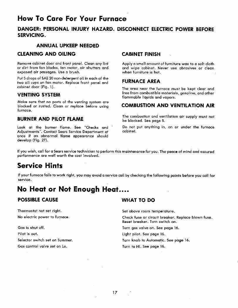
How To Care For Your Furnace
DANGER: PERSONAL INJURY HAZARD. DISCONNECT ELECTRIC POWER BEFORESERVICING.
ANNUAL UPKEEP NEEDED
CLEANING AND OILING CABINET FINISH
Remove cabinet door and front panel. Clean any lintor dirt from fan blades, fan motor, air shutters andexposed air passages. Use a brush.
Put 5 drops of SAE 20 non-detergent oil in each of thetwo oil cups on fan motor. Replace front panel andcabinet door (Fig. 1).
VENTING SYSTEM
Make sure that no parts of the venting system areblocked or rusted. Clean or replace before usingfurnace.
BURNER AND PILOT FLAME
Look at the burner flame. See "Checks andAdjustments". Contact Sears Service Department atonce if an abnormal flame appearance shoulddevelop (Fig. 27).
Apply a small amount of furniture wax to a soft clothand wipe cabinet. Never use abrasives or cleanwhen furniture is hot.
FURNACE AREA
The area near the furnace must be kept clear andfree from combustible materials, gasoline, and otherflammable liquids and vapors.
COMBUSTION AND VENTILATION AIR
The combustion and ventilation air supply must notbe blocked. See page 5.
Do not put anything in, on or under the furnacecabinet.
If you wish, call for a Sears service technician to perform this maintenance for you. The peace of mind and assuredperformance are well worth the cost involved.
Service Hints
If your furnace fails to work right, you may avoid a service call by checking the following points before you call forservice.
No Heat or Not Enough Heat....
POSSIBLE CAUSE WHAT TO DO
Thermostat not set right.
No electric power to furnace.
Gas is shut off.
Pilot is out.
Selector switch set on Summer.
Gas controlvalve set on Lo.
Set above room temperature.
Check fuse or circuit breaker. Replace blown fuse.Reset breaker. Turn switch on.
Turn gas valve on. See page 16.
Light pilot. See page 16.
Turn knob to Automatic. See page 16.
Turn to Ht. See page 16.
t7

WIRING DIAGRAM MODELS 867.736349 AND 867.736389
FANMOTOR
IIIIII GAS
VALVE
THERMOSTAT
iii
CONNECTION DIAGRAM
I I IIIIIII I U
TH
BK
W
R TAPED
BK HI SPEED
BL MED. SPEED
LIMIT CONTROL
BK
MANUAL
SELECTOR
SWITCH
FURNACE JUNCTION
TRANSFORMER
FAN JUNCTIONBOX
BL
HIGH
FAN
SWITCH
LOW
FAN
SWITCH
w
i i
LADDER DIAGRAM
_15 AMP
FUSEDDISCONNECT
SWITCH
RECOMMENDED
115 VOLT 60 HZ
TO APPROVED
ROUND
SUMMERMANUAL
SELECTOR
0 SWITCH
HIGH FAN SPEEDSWITCH
J GA@
VALVE
THERMOSTAT
R RED
W WHITE
BK BLACK
BL BLUE
TAPED
---low voltage field wiring
IIIIIIIIIIIII1_ II I'
11sv §0HZSUPPLY
IF ANY OF THE ORIGINAL WERE SUPPLIED WITH THE FURNACE
MUST BE REPLACED, TYPE A-i orAF (IS0oC) WIRE MUST fie USED.
I IIIIIIIIIIIIIIIIILIIUIIIIIIIIIIIIIH I II
v
18
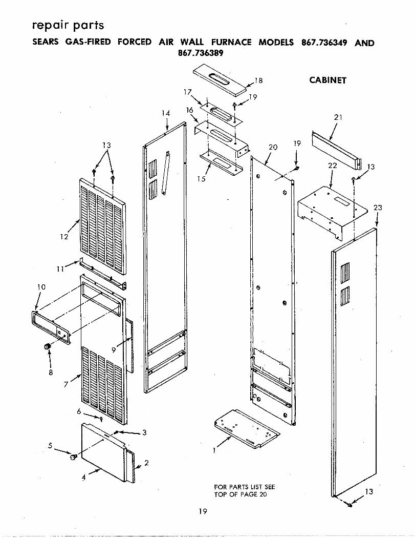
repair partsSEARS GAS-FIRED FORCED AIR WALL FURNACE
867.736389MODELS 867.736349 AND
12
|
8
5
13
2
17\
14 16
8
2O
FOR PARTS LIST SEETOP OF PAGE 20
19
CABINET
23
13
19

repair partsSEARS GAS-FIRED FORCED AIR WALL FURNACE MODELS
867.736389867.736349 AND
KEYNO.
123456789
I0II12131415161718192O212223
PARTNUMBERS
503898507245
STD51060250394139238
5027875051555018125052285074535O4447505158
STD61080350712650390650390850391188868
STD6110055041145042395041O6507128507674
* Standard Hardware Item.Part Not 111ustrated.
KEYNO.
123456789
I0II12131415161718192O2122232425262728293O
PART NUMBERS
503989STD610803
503928
CABINET
DESCRI#TION
Rail, Botto'mInsulation, Cabinet Door
*Screw, 6-32 x I/4" MachineDoor, CabinetKnob, DoorCatch, BulletPanel, FrontKnob, Selector SwitchInsulation, Front PanelPanel, ControlSupport, PanelPanel, Upper Louver
*Screw, 8 x 3/8" Sheet Metal (30 Req.)Panel, Left SidePlateSupport, VentCollar, FlueSeal
*Screw, lO x I/2" Sheet Metal (8 Req.)Panel, BackTrim, TopTop, BodyPanel, Right SideManual, Owners (F642-18880)
Purchase Locally. FOR PARTsiL(uSTRATIONSEE PAGE 19
RODY
DESCRIPTION
Shield, Burner Box*Screw, 8 x 3/8" Sheet Metal (20 Req.)
Plate, Bottom504016 Gasket, Bottom Plate
STD611007 *Screw, I0 x I" Sheet Metal (4 Req.)504336 Plate, Combustion Chamber Bottom504337504751503884503971503883504264504247504059503977
Gasket, Combustion Chamber Bottom PlateChamber, Combustion (2 Req.) (Includes 7 & 9)Gasket, Combustion Chamber to Radiator (2 Req.)RadiatorGasket (Radiator to Diverter)Extension, DiverterGasket (2 Req.)GasketDiverter
STD511005 *Screw, 10-24 x I/2" Machine C2 Req.)STD55_IIO *Lockwasher, No. 10 Split (2 Req.)STD541010 *Nut, I0-24 Hex (2 Req.}
504828 Support, Shield503987503986507129502043504522504521507133507131507132
STD610805STD611005
* Standard Hardware Item._ Part Not Illustrated.
Shield, BodyCover, SwitchSupport, SwitchSwitch, SelectorBaffle, SwitchSupport, Switch (Selector Switch)Switch, High Temperature FanSwitch, Low Temperature FanSwitch, Limit
*Screw, 7 x 3/8" Sheet Metal (6 Req,)*Screw, I0 x I/2" Sheet Metal (6 Req.)
Purchase Locally. FOR PARTS ILLUSTRATION20 SEE PAGE 21

repair partsSEARS GAS-FIRED AIR WALL FURNACE MODELS 867.736349 AND 867.736:389
2O 19
BODY
8_
7
7
3
2
2122
2
26
j27o @ 28
2t
25
FOR PARTS LISTSEEBOTTOM OF PAGE 20

repair partsSEARS GAS-FIRED AIR WALL FURNACE MODELS 867.736349 AND 867.736389
......14 13 12 11 9 7 1
__,1" ,, '
21 16 , / L
. ! I l,' l / 1
....... ...... 1¢_"
KEYNO.
1234
567
89
101112
131415
161718
192021
2223
PART NUMBERS
5074675074665045175045165074625O2191502287500757503873507461504027.507683507684
STD541010STD551110
504449STD551210STD511005STD541006
504507STD510603
60623427207
500370504871
DESCRIPTION
Wire,Wire,Wire,Wire,Wire,Wire,Wire,Wire,Wire,Wire,Wire,
(Black) Selector Switch to Junction Box (57 't Long)(White) From Junction Box to Junction Box (77" Long)(Black) From High Fan Switch to Junction Box (22" Long)(Red) From High Fan Switch to Junction Box (24" Long)(White) From Selector Switch to High Fan Switch (40" Long)(White) From High Fan Switch to Fan Switch (4" Long)(White and White) (Includes No. 5 and 6)(Black) Fan Switch to Limit Switch (4" Long)(Red and Black) (Includes Nos. 8 and I0)(Red) From Selector Switch to Fan Switch (40" Long)(Red) From Limit Switch to Junction Box (92" Long)
Wire, (White) "C" on Transformer to "TR" on Gas Valve (7" Long)Wire, (Black) "R" on Transformer to "TH-TR" on Gas Valve (7" Lon{
*Nut, 10-24 Square*Lockwasher, No. I0 Split
Box, Junction*Lockwasher, No. I0 External Tooth*Screw, 10-24 x I/2" Machine*Nut, 6-32 Hex (2 Req.)
Cover, Junction Box*Screw, 6-32 x 5/16" Machine (2 Req.)
Transformer, 24V./20VA.*Screw, 6-32 x I-I/4" Machine (2 Req.)
Wire, 25 Feet, 2-Wire ThermostatThermostat, Wall
* Standard Hardware Item. Purchase Locally.Part Not Illustrated.
22
repair parts
SEARS GAS-FIRED AIR WALL FURNACE MODELS 867.736349 AND 867.736389
KEYNO.
123456789
I0II121314
PART NUMBERS
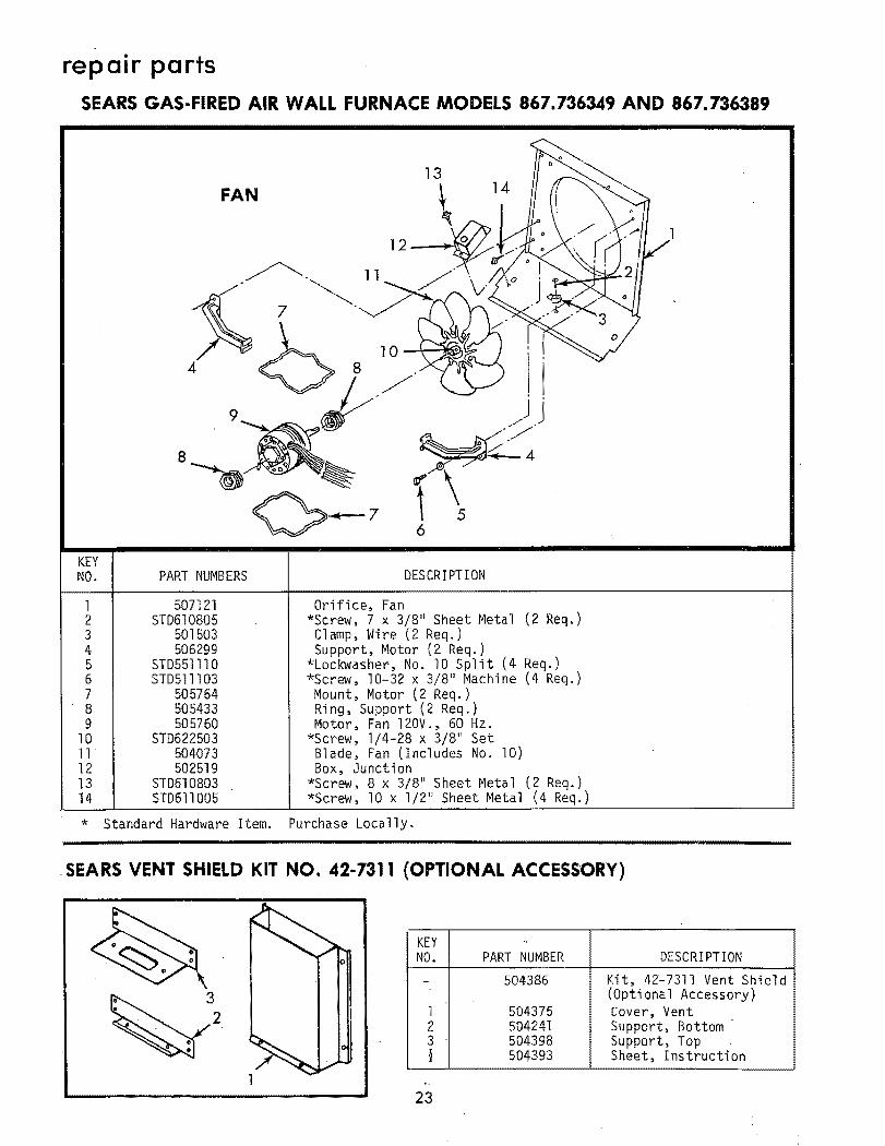
507121STD610805
501503506299
STD551110STD5111 O3
505764505433505760
STD6225035O4073502519
STD610803STD611005
DESCRIPTION
Orifice, Fan*Screw, 7 x 3/8" Sheet Metal (2 Req.)
Clamp, Wire (2 Req.)Support, Motor (2 Req.)
*Lockwasher, No. I0 Split (4 Req.)*Screw, 10-32 × 3/8" Machine (4 Req.)
Mount, Motor (2 Req.)Ring, Support (2 Req.)Motor, Fan 120V._ 60 Hz.
*Screw, I/4-28 x 3/8" SetBlade, Fan (Includes No. I0)Box, Junction
*Screw, 8 x 3/8" Sheet Metal (2 Req.)*Screw, I0 x I/2" Sheet Metal (4 Req.)
* Standard Hardware Item. Purchase Locally.,,,,,,,,,,,,,,,,,,,,,,
I IIIIIIIIIIIIIIIIII
SEARS VENT SHIELD KIT NO. 42-1311 (OPTIONAL ACCESSORY)
1
KEYNO. PART NUMBER
- 504386
123
23
504375504241504398504393
DESCRIPTION
Kit, 42"7311 Vent Shield(Optional Accessory)Cover, VentSupport, BottomSupport, TopSheet, Instruction

repair partsSEARS GAS-FDRED FORCED AIR WALL FURNACE
867.736389MODELS 867.736349 AND
16
T15
27
26
2O
17
2O
BURNER COMPARTMENT
18
17
11
6 7
12
13
4
15
14
16
3
2
FOR PARTSLISTSEEPAGE 25
24

repair parts
SEARS GAS-FIRED FORCED AIR WALL FURNACE
867.736389
MODELS 867.736349 AND
BURNER COMPARTMENT
KEYNO.
12344567899
I0I0II1213141415161718192O21222324252627
PARTNUMBERS867.736349
504826STD611005
504072507677
505118STD511107
89030
FOR MODELS867.736389
29441503036
504455
507552503758
4695830368
STD51100322000
5O5757STD511005
503961STD541010
64479505755
STD511007505756
STD510803STD551110STD611007
506537
504826STD611005
504072
507678505118
STD51110789O3029441
503037mm--
504456507552503758
46958
46852STD511003
22000505757
STDSIIO05503961
STD54101064479
505755STD511007
505756STD510803STD551110STD611007
506537
DESCRIPTION
Shield, Burner Hea't
*Screw, I0 x I/2" Sheet Metal (7 Req.)Plate, Division
#Valve, Gas (Nat.)#Valve, Gas (L.P.)
Support, Valve*Screw, 10-32 x 3/4" Machine
Tubing, PilotFerrule and Nut
#Orifice, Pilot (Nat. Gas)#Orifice, Pilot (L.P. Gas)#Pi_ot, Burner (Nat. Gas) (Includes No. 9)#Pilot, Burner (L:P. Gas) (Includes No. 9)
Manifold
ThermocoupleSleeve, Manifold (2 Req.)
#Orifice, Burner (Nat. Gas) (No. 36 Drill Size)#Orifice, Burner (L.P. Gas) (No. 52 Drill Size)*Screw, 10-24 x 5/16" Wing (2 Req.)
Shutter, Air (2 Req.)Burner (2 Req.)
*Screw, 10-24 x I/2" Machine (2 Req.)Bracket, Burner (2 Req.)
*Nut, 10-24 Square (4 Req.)*Nut, "J" Speed (2 Req.)*Nut, 8-32 "U" Speed*Screw, 10-24 x 5/8" Machine (2 Req.)
Support, Pilot*Screw, 8-32 x 3/8" Machine*Lockwasher, No. I0 Split (2 Req.)*Screw, I0 x I" Sheet Metal (2 Req.)
Plate, Lighting Instruction
*-Standard Hardware Item. -- Purchase Locally.Part Not Illustrated.
# Be Sure Parts Being Ordered Are For Typeof Gas Being Used.
i i|ll i i
.... FORPARTSILLUSTRATIONSEE PAGE24
(2 Req.)(2 Req.)
rlit Ilml I"11IIII
SEARS HORIZONTAL VENT KIT NO. 42-1369 (OPTIONAL ACCESSORY)• _, ,,, i ,
1
KEY
NO. PART NUMBER DESCRIPTION
- 506591
12
506590506588506592
Kit, 42-7369 Horizontal Vent(Optional Accessory)
Tee, Horizontal FlueShield, WallSheet, Instruction
25

repair partsSEARS GAS-FIRED FORCED AIR WALL FURNACE MODELS 867.736349 AND
867.736389............ i I ,= --
Sears Rear Wall RegisterStock No. 42-7313
(,Optional Accessory)
Kit -
1
. ',--
IIIIIIIIIIIII | I I
KEYNO.
1
34567
PART NUMBER
130358506953
STD610805506942506943506957506939506951
DESCRIPTION
*Screw, I0 x I" Round Head Wood (3 Req.)
Panel, Rear Register*Screw, 7 x 3/8" Sheet Metal (12 Req.)
Panel, Side Collar (2 Req.)Panel, Top and Bottom Collar (2 Req.)Deflector, AirBracket, HangerManual, Installation (F642-i2176)
Standard Hardware Items.Purchase Locally.Part Not lllustrated.
26

repair partsSEARS GAS-FIRED FORCED AIR WALL FURNACE MODELS 867.736349 AND 867.736389
Sears Rear Wall Register
__ Stock No. 42-7312
,3/ _?ptionai Accessory)
L , 1"_4
2 ' i _. • 7
_._ _ _'1 ._-.-_
<,,,. "" _
i i | i i i
Kit -
_EYNO.
12345
PART NUMBER
130358506946506939506957506943
STD6108055069425O6947
DESCRIPTION
*Screw, I0 x I" Round Head Wood (3 Req.)Panel, Rear RegisterBracket, HangerDeflector, AirPanel, Top and Bottom Collar (2 Req.)
*Screw, 7 x 3/8" Sheet Metal (12 Req.)Panel, Side Collar (2 Req.)Manual, Installation (F642-12276)
* Standard Hardware Items.Purchase Locally.Part Not lllustrated
27

GAS-FIREDFORCED AIR
WALL FURNACE
Now that you have purchased your wall furnace, should a
need ever exist for repair parts or service, simply contact any
Sears Service Center and most Sears, Roebuck a_d Co.
stores. Be sureto provide all pertinent facts when you call or
visit.
The model number of your Wall Furnace will be found on the
Rating Plate located on the Panel directly above the Gas
Valve.
When ordering repair parts always give the following
information:
• PART NUMBER
• MODEL NUMBER
. PART DESCRIPTION
• NAME OF ITEM
Atl parts listed may be ordered from any Sears Service:
Center and most Sears stores.
If the parts you need are not stocked locally, your order will
be electronically transmitted to a Sears Repair Parts Distribu-
tion Center for handling.
When Sears arranges the installation, you can be sure the
job is done right. We will arrange for pLofessional Workman-
ship .... and we'll take care of the entire project. What's
more, during installation you get insured protection ....
against property damage and also against accidents to
workmen. AII you have to do is talk to your Sears salesperson
Or call your nearest Sears store today for detailed
information.
Sears, Roebuck and Co., Chicago, I!. 60684 U.S.A.F642-18880 507674
11-3-80L.T,I