Owner's Manual - Berklee College of Musicmpe.berklee.edu/documents/studio/manuals/effects/Lexicon...
69
LXP-5 Effects Processing Module Owner's Manual
-
Upload
truongdien -
Category
Documents
-
view
226 -
download
1
Transcript of Owner's Manual - Berklee College of Musicmpe.berklee.edu/documents/studio/manuals/effects/Lexicon...

LXP-5Effects
ProcessingModule
Owner's Manual

Owner's Manual
LXP-5Effects
ProcessingModule

Lexicon Part #070-07332 Rev 1
Unpacking and InspectionAfter unpacking the LXP-5, save all packing materials in case you ever need to ship the unit.Thoroughly inspect the LXP-5 and packing materials for signs of damage. Report any shipmentdamage to the carrier at once; report equipment malfunction to your dealer.
This equipment generates and uses radio frequency energy and if not installed and usedproperly, that is, in strict accordance with the manufacturer's instructions, may cause interfer-ence to radio and television reception. It has been type tested and found to comply with the limitsfor a Class A computing device in accordance with the specifications in Subpart J of Part 15of FCC Rules, which are designated to provide reasonable protection against such interferencein a residential installation. However, there is no guarantee that interference will not occur ina particular installation. If this equipment does cause interference to radio or televisionreception, which can be determined by turning the equipment OFF and ON, the user isencouraged to try to correct the interference by one or more of the following measures:
Reorient the receiving antennaRelocate the computer with respect to the receiverMove the computer away from the receiverPlug the computer into a different outlet so that the computer and receiver are ondifferent branch circuits.
If necessary, the user should consult the dealer or an experienced radio/television technicianfor additional suggestions. The user may find the following booklet prepared by the FederalCommunications Commission helpful:
"How to identify and Resolve Radio/TV Interference Problems."This booklet is available from the U.S. Government Printing Office, Washington, DC 20402,Stock No. 004-000-00345-4.
Notice
Copyright 1989, 1995All Rights Reserved.
Lexicon Inc.3 Oak ParkBedford, MA 01730USATelephone 781-280-0300Fax 781-280-0490

Table of Contents
Introduction1. Installing the LXP-5
Unpacking ..........................................................................1-1Mounting ............................................................................ 1-1Power ................................................................................1-1Front Panel Controls ..........................................................1-2Rear Panel Connectors .....................................................1-3Audio Connections ............................................................1-4
2. Front Panel OperationSetting Audio Levels ..........................................................2-1LED Signals .......................................................................2-3Selecting Preset Programs ................................................ 2-4User Memory ..................................................................... 2-7Creating Your Own Sounds .............................................2-11Storing and Recalling sounds ..........................................2-19Footswitch Operation .......................................................2-22
3.MIDI OperationAccessing Programs ..........................................................3-1Patches and Dynamic MIDI ..............................................3-4Creating Patches Using MIDI SysEx Data ......................3-11Assigning Switches as Control Sources ..........................3-12
4. MIDI Implementation DataData/Event Requests ......................................................... 4-1Transmit/Receive Data ......................................................4-2Parameter Definitions ........................................................ 4-6Microcode Parameters ......................................................4-9Implementation Chart ......................................................4-14
5. Specifications
User Program Log Sheet

Introduction
Congratulations on your purchase of the LXP-5 Effects Processing Module!You are about to experience superb sound quality, a full range of pitchshifting, delay and reverb effects, fast intuitive editing of preset sounds, andan industry-leading MIDI implementation.
The LXP-5 offers a rich and distinctive palette of special effects, including128 programs to get you started — 64 preset effects programs and anadditional 64 programs stored in RAM user memory locations. Eachprogram has up to five variable parameters that you can adjust for subtle ordramatic changes in the program’s sound, and you can store as many as 128customized programs in user memory. All of the LXP-5 functions areaccessible from the front panel, or via MIDI, providing truly world-classflexibility and control. From pitch shifting to stereo delays and flanging, theLXP-5 delivers superior performance. Whether you are a producer, engi-neer, or musician—whether you work on stage or in the studio—the LXP-5will quickly become an indispensible part of your sound.
We’re confident you’ll find that the LXP-5’s unique combination of state-of-the-art sound and extraordinary versatility is exactly what you’re looking for.A Quick Reference card provides the basics of operation in a compactformat to get you up and running as quickly as possible — but to make sureyou don’t miss out on anything, we’d like you to read this manual. It providesa thorough explanation of both front panel and MIDI operation, programdescriptions, and complete MIDI Implementation data — all the informationyou need to access the full power of the LXP-5.

1-1
Installing the LXP-5
1. Installing the LXP-5
UnpackingAfter unpacking the LXP-5, save all packing materials in case you ever needto ship the unit. Thoroughly inspect the LXP-5 and packing materials forsigns of damage. Report any shipment damage to the carrier at once. Thefollowing accessories are included with the LXP-5:
1. Quick Reference card2. Owner's Manual3. Power pack (USA Part # 470-07345)4. Warranty card (USA only)
PowerConnect the LXP-5 power pack to an appropriate AC wall socket, and thecable end to the LXP-5 power connector. The LXP-5 must be used only withthe supplied power pack. Voltage requirements are printed on the powerpack. The LXP-5 has no power switch – it can be left on all the time. To keepthe power plug from working loose from the rear of the unit during transport,you may wish to apply a small amount of silicone sealer to the plug afterinserting it.
MountingThe LXP-5 measures 8.5"W x 1.7"H x 9.5"d (215.9 x 43.2 x 241.3 mm). Theoptional rack mounting kit (A-LXP-R) handles one or two units in a singlerack space. Whatever mounting method you use, make sure that the LXP-5 is securely screwed into the rack adapter – "friction fit" or double-stick tapeinstallations may allow units to loosen during transportation, resulting indamage.
The maximum ambient operating temperature is 35°C (95°F). Provideadequate ventilation if the LXP-5 is mounted in a closed rack with heat-producing equipment such as synthesizer modules, effects units, or poweramplifiers. Avoid mounting the LXP-5 directly above power amplifiers.

1-2
LXP-5 Owner's Manual
AdjustUsed to adjust programparameter(s), or to ad-just the selected pa-rameter in Edit Mode.
LXP-5 Front Panel Controls
InputSets the audio inputlevel.
BYPASS
SELECT
LXP-5
LEARN
exicon
EDIT
12345678
PRESET USERINPUT MIX OUTPUT
ABC
PITCHDELAY
CHORUSMULTI
OutputControls the signallevel sent to the LXP-5outputs.
MixControls the ratio of dry(source) to wet (effect)signal present at theLXP-5 outputs. (Turnthe control all the wayto the left for 100% dry/0% wet.)
Level IndicatorsThe left LED indicatessignal present; the rightflashes red when thesignal is -3dB frompeak overload.
Function and SelectUsed for selection offactory presets, Usermemories, Bypass andthree edit modes.
Learn LEDConfirms that power ison, and blinks in red orgreen at different ratesto indicate LXP-5 sta-tus.
LearnThis button is used tostore and edit pro-grams, to learnpatches and, with anexternal MIDI device,to select MIDI channel.

1-3
Installing the LXP-5
Dynamic MIDI® FOOTSWITCH POWER9V AC1.5A
ASSEMBLED IN HONG KONGLEXICON LXP-5
MIDI
IN
OUTPUTS INPUTS
LL RR
THIS EQUIPMENT COMPLIES WITH THE REQUIREMENTS INPART 15 OF FCC RULES FOR A CLASS A COMPUTING DEVICEOUT - THRU
LXP-5 Rear Panel Connections
MIDI INReceives MIDI infor-mation from other MIDIequipment such asmaster keyboard con-trollers, MIDI foot con-trollers, sequencersand synthesizers.
Outputs (L and R)Single-ended (unbal-anced) stereo outputsprovide +4dBu nominaloutput level.
FootswitchConnector for toggle(Push on/push off) ormomentary contactfootswitch.
MIDI THRU (OUT)With the recessed slideswitch set for MIDITHRU, any MIDI datareceived is sent withoutchange. The recessedslide switch can also beset for MIDI OUT.
PowerAccepts power fromthe supplied powerpack.
Inputs (L and R)Single-ended (unbal-anced) inputs acceptlevels from -25 to+20dBu. Input imped-ance is 50 kilohms instereo, 25 kilohms inmono.

1-4
LXP-5 Owner's Manual
Audio Connections
This section outlines several connection possibilities for the LXP-5. Be-cause each sound system is unique, we recommend experimentation toarrive at the best configuration for your system. Always check connectionsfor proper impedance, polarity, and levels.
Audio connections to the LXP-5 are unbalanced, and should be made withhigh quality shielded cables with 1/4" tip-sleeve phone jacks at the LXP-5end. The connectors must be wired as shown below:
If only 1/4" tip-ring-sleeve phone jacks are available, they must be wired asshown:
Sleeve - Shield/Ground
Tip - High
Sleeve - Shield/Ground
Tip - High
Ring - Connect to Sleeve
Mono or stereo?The LXP-5 produces wonderful stereo effects from either mono or stereosignal sources. For mono sources, use either of the two input connectors;the dry signal appears (along with the stereo effects) in mono at both outputconnectors. For instruments and sources with stereo outputs, use bothinputs. We recommend using both LXP-5 outputs whenever possible but, ifmono output is required, you can use just one of the two output connectors.When only one output is used, the left and right signals are summedinternally .
Some of the examples on the following pages use stereo instruments andamplification systems, others use mono. Feel free to adapt the examples toyour specific requirements.

1-5
Installing the LXP-5
Connection to a mixing console's effects sendsIf you will be using an LXP-5 as your primary effects unit, and your systemincludes a console with one or more auxiliary (effects) sends, connect theLXP-5 as shown above. In most applications, it is preferable to connect theLXP-5 outputs to two of the console's input channel strips, panned full leftand right, rather than the effects returns. This allows the greatest flexibilityin routing and equalization.
In this configuration the console controls are used to set the amount of effectheard—the LXP-5 front panel MIX control should be set fully clockwise for100% wet.
Channel Input orEffects Return (L)
Channel Input orEffects Return (R)
EffectsSend
Input(L or R) R OutputL Output
BYPASS
SELECT
LXP-5
LEARN
exicon
EDIT
12345678
PRESET USERINPUT MIX OUTPUT
ABC
PITCHDELAY
CHORUSMULTI

1-6
LXP-5 Owner's Manual
Channel Input(pan left)
Channel Input(pan right)
LXP-5L Output
LXP-5R Output
SynthR Output
SynthL Output
BYPASS
SELECT
LXP-5
LEARN
exicon
EDIT
12345678
PRESET USERINPUT MIX OUTPUT
ABC
PITCHDELAY
CHORUSMULTI
Connection between instrument and consoleIn some applications (such as when an LXP-5 is used for a single instrument)it may be desirable to patch the LXP-5 between the instrument and console.This makes it possible to keep the LXP-5 up on stage with other MIDI gear,rather than in the console effects rack, making MIDI control much easier.
In this configuration, the LXP-5 front panel MIX control is used to set thebalance between wet and dry sound.
In In

1-7
Installing the LXP-5
AmpR Input
AmpL Input
GuitarOutput
LXP-5 Input(L or R) LXP-5
L OutputLXP-5R Output
BYPASS
SELECT
LXP-5
LEARN
exicon
EDIT
12345678
PRESET USERINPUT MIX OUTPUT
ABC
PITCHDELAY
CHORUSMULTI
Connection between instrument and amplifierFor a very spacious guitar sound, connect the LXP-5 between a guitar andtwo amp and speaker stacks. The only problem with this setup is that if youuse overdrive distortion created by the amplifier, changing settings on theLXP-5 also affects the quantity and quality of your distortion. If you use aseparate distortion box, you can get around this problem by connecting itbefore the LXP-5. If you prefer amplifier-generated distortion, try the setupshown on the next page.
1-8
LXP-5 Owner's Manual
Direct orPreamp output
L and R Speaker Outputs from Power Amp
Amp orPreamp
InputGuitarOutput
AmpR Input
AmpL Input
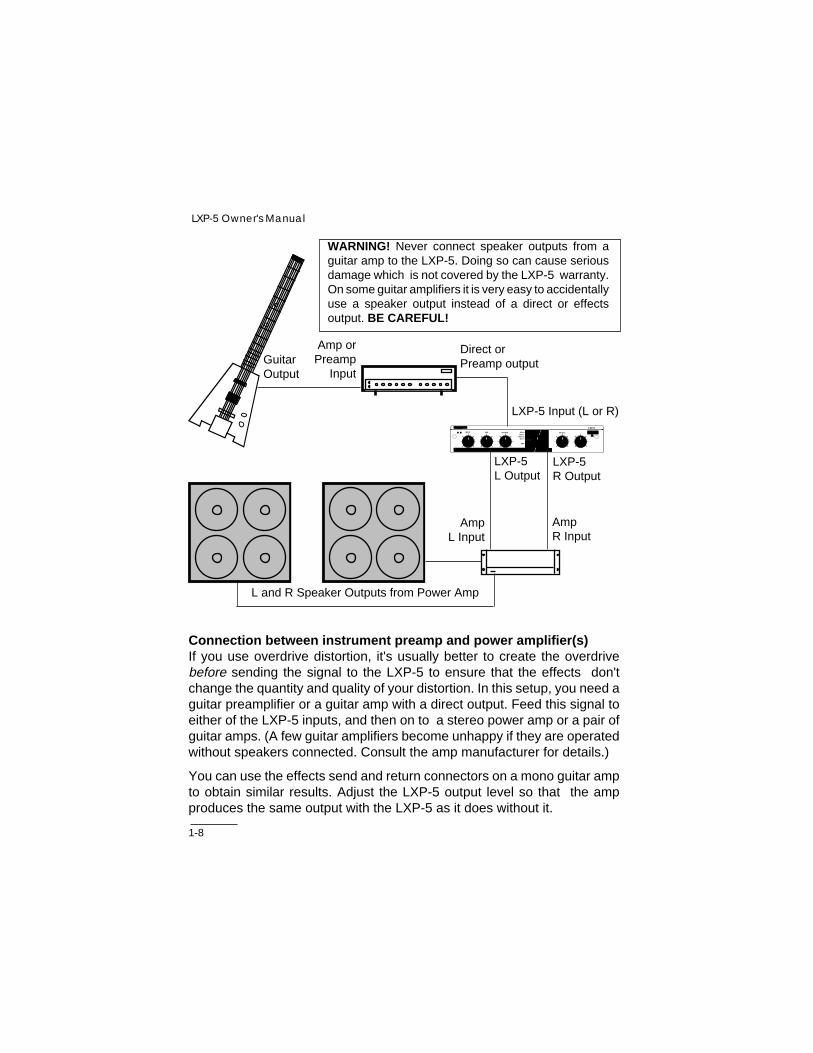
WARNING! Never connect speaker outputs from aguitar amp to the LXP-5. Doing so can cause seriousdamage which is not covered by the LXP-5 warranty.On some guitar amplifiers it is very easy to accidentallyuse a speaker output instead of a direct or effectsoutput. BE CAREFUL!
LXP-5L Output
LXP-5R Output
LXP-5 Input (L or R)
Connection between instrument preamp and power amplifier(s)If you use overdrive distortion, it's usually better to create the overdrivebefore sending the signal to the LXP-5 to ensure that the effects don'tchange the quantity and quality of your distortion. In this setup, you need aguitar preamplifier or a guitar amp with a direct output. Feed this signal toeither of the LXP-5 inputs, and then on to a stereo power amp or a pair ofguitar amps. (A few guitar amplifiers become unhappy if they are operatedwithout speakers connected. Consult the amp manufacturer for details.)
You can use the effects send and return connectors on a mono guitar ampto obtain similar results. Adjust the LXP-5 output level so that the ampproduces the same output with the LXP-5 as it does without it.
BYPASS
SELECT
LXP-5
LEARN
exicon
EDIT
12345678
PRESET USERINPUT MIX OUTPUT
ABC
PITCHDELAY
CHORUSMULTI

1-9
Installing the LXP-5
Connection between drum machine and consoleUsing two LXP-5 units between your drum machine and console can makeyour drum machine sound much more exciting, since it allows you to processthe all-important snare drum separately from the rest of the mix. Make sureyou remove the snare from the drum machine's main stereo mix.
Drum machine'sstereo outputs
Drum machine's individualoutput for snare drum
ConsoleInputs
ConsoleInputs
LXP-5 Inputs(L and R)
LXP-5 Outputs(L and R)
LXP-5 L Input
LXP-5 Outputs(L and R)
BYPASS
SELECT
LXP-5
LEARN
exicon
EDIT
12345678
PRESET USERINPUT MIX OUTPUT
ABC
PITCHDELAY
CHORUSMULTI
BYPASS
SELECT
LXP-5
LEARN
exicon
EDIT
12345678
PRESET USERINPUT MIX OUTPUT
ABC
PITCHDELAY
CHORUSMULTI

1-10
LXP-5 Owner's Manual
2-1
Front Panel Operation
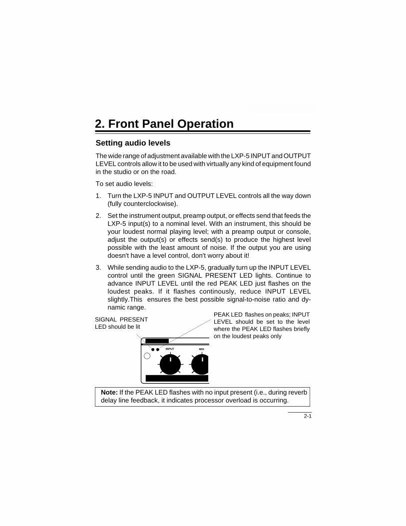
Note: If the PEAK LED flashes with no input present (i.e., during reverbdelay line feedback, it indicates processor overload is occurring.
SIGNAL PRESENTLED should be lit
PEAK LED flashes on peaks; INPUTLEVEL should be set to the levelwhere the PEAK LED flashes brieflyon the loudest peaks only
exicon
INPUT MIX
Setting audio levels
The wide range of adjustment available with the LXP-5 INPUT and OUTPUTLEVEL controls allow it to be used with virtually any kind of equipment foundin the studio or on the road.
To set audio levels:
1. Turn the LXP-5 INPUT and OUTPUT LEVEL controls all the way down(fully counterclockwise).
2. Set the instrument output, preamp output, or effects send that feeds theLXP-5 input(s) to a nominal level. With an instrument, this should beyour loudest normal playing level; with a preamp output or console,adjust the output(s) or effects send(s) to produce the highest levelpossible with the least amount of noise. If the output you are usingdoesn't have a level control, don't worry about it!
3. While sending audio to the LXP-5, gradually turn up the INPUT LEVELcontrol until the green SIGNAL PRESENT LED lights. Continue toadvance INPUT LEVEL until the red PEAK LED just flashes on theloudest peaks. If it flashes continously, reduce INPUT LEVELslightly.This ensures the best possible signal-to-noise ratio and dy-namic range.
2. Front Panel Operation

2-2
LXP-5 Owner's Manual
5. If you are using an instrument amplifier or preamplifier, start with theLXP-5 MIX control straight up (50% effect). Gradually increase theOUTPUT LEVEL control until the audio level heard from the amplifier isapproximately the same as when the LXP-5 is not connected.
The best setting for MIX depends on which program you are using, andto a great extent, your personal taste; feel free to experiment.
MIX setting to use whenthe LXP-5 is patched toconsole effects send(s)
When using an instrumentamplifier or preamplifier,the ideal MIX setting isgenerally somewhere inthis range
n
INPUT MIX OUTPUT
n
INPUT MIX OUTPUT
4. If the LXP-5 inputs are connected to a console effects send, and theoutputs are connected to console channel strip inputs, set the console'sinput level trim and fader to a setting typically used for line level inputs.Then set the MIX control fully clockwise (100% effect) and gradually turnup the LXP-5 OUTPUT LEVEL control until the right amount of audio ispresent at the console.

2-3
Front Panel Operation
LED signals
The front panel LEARN indicator is a bicolor (red/green) LED that performsseveral functions:
Register Store: success or failureThe LEARN LED will blink at a 6 Hz rate for approximately 2 seconds — ingreen to indicate succesful register storage, red to indicate failure to storeto a register.
MIDI Data PresentThe LEARN LED will flicker (in whatever its current color) to indicate LXP-5 recognition of incoming MIDI messages. System Common messages,non-LXP-5 SysEx messages and any message on channels other than theselected channel will not activate the LED.
Parameter Editing StatusWhen not receiving MIDI, or indicating storage success, the LED will tell youtwo things about the parameter editing status of the sound you are running:
1. Has the selected parameter been changed from the stored value?If the selected parameter matches the stored value, the LED will begreen. Otherwise it will be red.
2. Do the knobs correctly indicate the sound that is running?If the knobs are accurate the LED will be steady. If the knobs are notaccurate (for example, after loading a program or changing theselected parameter via MIDI), the LED will blink.
GREEN RED
LED Steady Parameter Unchanged Parameter ChangedKnobs Accurate Knobs Accurate
LED Blinks Parameter Unchanged Parameter ChangedKnobs Inaccurate Knobs Inaccurate

2-4
LXP-5 Owner's Manual
Presets and User Programs
Selecting LXP-5 preset programs
Any one of 64 preset effects programs can be selected by turning theFUNCTION and SELECT knobs on the front panel. To select a preset, firstturn FUNCTION to one of the four available preset types: PITCH, DELAY,CHORUS or MULTI(-effect). Then, turn SELECT to one of the 16 presetswithin the chosen type.
Use FUNCTION to select apreset type.
BYPASS
SELECT
EDIT
12345678
PRESET USER
ABC
PITCHDELAY
CHORUSMULTI
Use SELECT to choosea specific preset.
LXP-5
LEARN
Use ADJUST to changethe sound of the preset.
Once a preset has been chosen, the sound can be modified with theADJUST knob. Program parameters can be altered in Edit mode, describedlater in this chapter.

2-5
Front Panel Operation
LXP-5 Presets
SELECTPosition
MIN23456789
101112131415
MAX
PRESET ADJUSTParameters
Dly 1,2-crs,Rvb BalDly 1,2-crs,Rvb Bal,Fbk 1
Decay Time,Dly 2-crs,Fbk 1Decay Time,Dly 1,2-crs,Fbk 1
Decay Time,Dly 1,2-crsDecay Time,Dly 1,2-crs,Fbk 1Decay Time,Dly 1,2-crs,Fbk 1
Dly 1,2-crs,Fbk 1Dly 1,2-crs,Fbk 1Dly 1-crs,Fbk 1Dly 1-crs,Fbk 1Dly 1-crs,Fbk 1
Dly 1-fin,Dly 2-crs,Fbk 1Dly 1-fin,Dly 2-crs,Fbk 1
Dly 1-crsDly 1-crs
DELAY
#17181920212223242526272829303132
NameEcho Delay
Stereo DelaySlap EchoMid Slap
Stereo SlapDiffuse EchoImage Delay
Bounce DelayBounce LoopAmbient Loop
Echo LoopFilter Delay
Robot 1Robot 2
Short DelayLong Delay
PITCH
SELECTPosition
MIN23456789
101112131415
MAX
PRESET
NameFourth Down
Fifth Up Octave Down
Two Octaves DownOctave UpTunnel Up
Tunnel DownGlissando Up
Glissando DownDiminishedSuspendedLow OctaveMid OctaveHigh Octave
SemituneFine Tune
#12345678910111213141516
ADJUSTParametersPitch IntervalPitch IntervalPitch Interval
LFO RateLFO Rate
Dly 2,3-crs,Rvb Bal,Pitch AdjDly 2,3-crs,Rvb Bal,Pitch Adj
Dly 2,3-crs,Decay Time,Pitch IntrvlDly 2,3-crs,Decay Time,Pitch Intrvl
Dly 2,3-crs,Decay TimeDly 2,3-crs,Decay Time
Pitch IntervalPitch IntervalPitch IntervalPitch AdjustPitch Adjust

2-6
LXP-5 Owner's Manual
MULTI
SELECTPosition
MIN23456789
101112131415
MAX
PRESET
NameStrange RoomDown Room
Ambient Slap Slow RiseSlow Fall
Octave RoomZoom
Bounce FourthSlap RoomEcho RoomDark ClosetSmall Bright
Medium BrightMedium DarkLarge BrightHuge Room
#49505152535455565758596061626364
ADJUSTParameters
Dly 2-crs,Pitch Adj,Fbk 2Pitch Adj,Fbk 2
Dly 2-crs,Decay TimeDly 2-crs,Fbk 2,Hicut
Dly 2-crs,Dly 3-fin,Fbk 2,LocutFbk 2,Hicut,Decay Time
Fbk 2,Pitch IntervalDly 2-crs,Fbk 1,Bass Mult,Dcy TimeDly 2-crs,Fbk 1,Bass Mult,Dcy TimeDly 2-crs,Fbk1,Rvb Bal,Decay Time
Treble Decay,Hicut,Decay TimeDecay TimeDecay TimeDecay Time
Dly 2-crs,Decay TimeDly 2-crs,Decay Time
CHORUS
NameChorus
Ambient ImageComb AmbienceAmbient Detune
Dry DetuneSlap Detune
Resonant SweepDiffuse SweepSlap SweepEcho DetuneStep DetuneRoto MotionRoto Slap
Slow Res. SweepSlap Flange
Diffuse Flange
#33343536373839404142434445464748
SELECTPosition
MIN23456789
101112131415
MAX
PRESET ADJUSTParameters
Pitch Adj,Dly 3-crsDly 3-crs,Decay Time,Rvb Time
Dly 2,3-crs,LFO RateDly 2,3-crs,LFO RateDly 2,3-crs,LFO RateDly 1,3-crs,LFO RateDly 1,3-crs,LFO RateDly 1,3-crs,LFO RateDly 1,3-crs,LFO RateDly 1,3-crs,LFO Rate
Dly 3-crsLFO Rate,Patch 3 (LFO to Dly 2-fin)LFO Rate,Patch 3 (LFO to Dly 2-fin)Rvb Bal,Patch 3 (LFO to Dly 2-fin)Rvb Bal,Patch 3 (LFO to Dly 2-fin)
LFO Rate,Patch 3 (LFO to Dly 2-fin)

2-7
Front Panel Operation
User Memory
The LXP-5 contains 128 memory locations divided among 8 User MemoryBanks as follows.
USER 1 1-16 USER 5 65-80USER 2 17-32 USER 6 81-96USER 3 33-48 USER 7 97-112USER 4 49-64 USER 8 113-128
NOTE: All User programs are volatile — storing a new program willoverwrite the previously stored program.
When shipped from the factory, THE LXP-5 contains a duplicate set of thePreset programs at locations 1-64 (available at FUNCTION settings: USER1-4).
Sixty-four different programs are provided at locations 65-128. Theseprograms make use of both ADJUST Knob patches and MIDI patches(described in Chapters 3 and 4). These User presets, provided in UserBanks 5-8, are shown in the following tables.
.
2-8
LXP-5 Owner's Manual
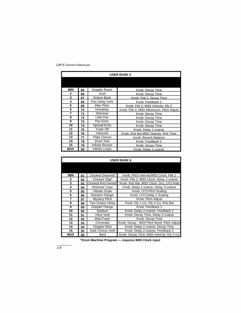
USER BANK 5
SELECTPosition
MIN23456789101112131415
MAX
PRESET
NameDoppler Room
KnotOctave Back
Pan Delay VerbAfter PitchVelodelayShimmerLittle PanPan Echo
Spread EchoTrade OffVeloverb
Plate ChorusDrum Teel
Infinite ReverbInfinite Loops
#65666768697071727374757677787980
PATCHAssignments
Knob: Decay TimeKnob: Decay Time
Knob: Fbk 2, Decay TimeKnob: Feedback 2
Knob: Fbk 2; MIDI Velocity: Dly 2Knob: Fbk 2; MIDI Aftertouch: Pitch Adjust
Knob: Decay TimeKnob: Decay TimeKnob: Decay TimeKnob: Decay Time
Knob: Delay 1-coarseKnob: Rvb Bal MIDI Velocity: Rvb Time
Knob: Reverb BalanceKnob: Feedback 2Knob: Decay Time
Knob: Delay 1-coarse
USER BANK 6
SELECTPosition
MIN23456789101112131415
MAX
PRESET
NameClocked Descend*
Clocked Slap*Clocked Rvb Flange*
Shimmer CaveVibrato Scale
Random FlangeMystery Pitch
Two Octave DelayDoppler Flange
StadiumVibra VerbWait FrashChromatic
Doppler ModDark Chorus Verb
Bent
#81828384858687888990919293949596
PATCHAssignments
Knob: Pitch Interval;MIDI Clock: Fbk 2Knob: Fbk 2; MIDI Clock: Delay 2-coarse
Knob: Rvb Bal; MIDI Clock: Dcy, LFO RateKnob: Delay 2-coarse, Delay 3-coarse
Knob: LFO-Pitch ScalingKnob: LFO-Delay 2 Scaling
Knob: Pitch AdjustKnob: Dly 1-crs, Dly 3-crs, Rvb Bal
Knob: Feedback 1Knob: Delay 2-coarse, Feedback 2Knob: Decay Time, Delay 2-coarse
Knob: Decay TimeKnob: Decay ; MIDI Pitch Bend: Pitch Adjust
Knob: Delay 2-coarse; Decay TimeKnob: Delay 2-coarse; Feedback 2
Knob: Decay Time; MIDI Velocity: Dly 2-crs
*Drum Machine Program — requires MIDI Clock input
2-9
Front Panel Operation
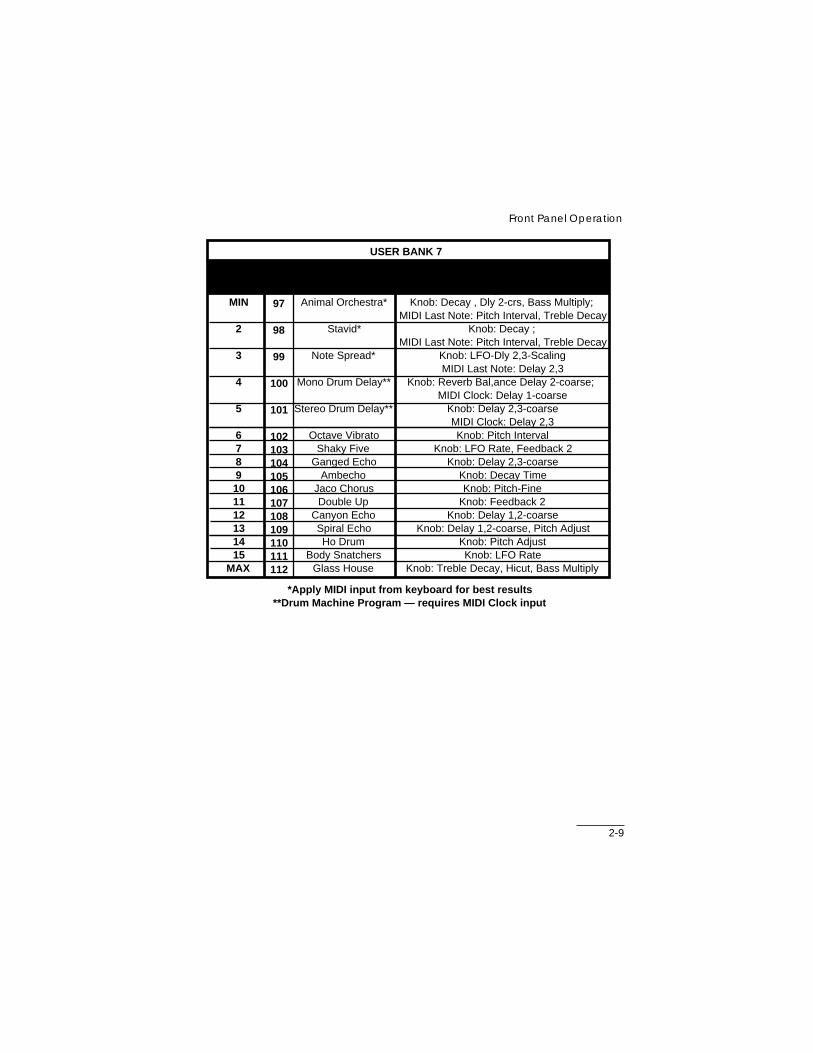
USER BANK 7
SELECTPosition
MIN
2
3
4
5
6789101112131415
MAX
PRESET
NameAnimal Orchestra*
Stavid*
Note Spread*
Mono Drum Delay**
Stereo Drum Delay**
Octave VibratoShaky Five
Ganged EchoAmbecho
Jaco ChorusDouble Up
Canyon EchoSpiral EchoHo Drum
Body SnatchersGlass House
#97
98
99
100
101
102103104105106107108109110111112
PATCHAssignments
Knob: Decay , Dly 2-crs, Bass Multiply; MIDI Last Note: Pitch Interval, Treble Decay
Knob: Decay ; MIDI Last Note: Pitch Interval, Treble Decay
Knob: LFO-Dly 2,3-ScalingMIDI Last Note: Delay 2,3
Knob: Reverb Bal,ance Delay 2-coarse; MIDI Clock: Delay 1-coarse
Knob: Delay 2,3-coarseMIDI Clock: Delay 2,3Knob: Pitch Interval
Knob: LFO Rate, Feedback 2Knob: Delay 2,3-coarse
Knob: Decay TimeKnob: Pitch-Fine
Knob: Feedback 2Knob: Delay 1,2-coarse
Knob: Delay 1,2-coarse, Pitch AdjustKnob: Pitch AdjustKnob: LFO Rate
Knob: Treble Decay, Hicut, Bass Multiply
*Apply MIDI input from keyboard for best results**Drum Machine Program — requires MIDI Clock input

2-10
LXP-5 Owner's Manual
USER BANK 8
SELECTPosition
MIN2
3
4
5
6
78
910
11
12131415
MAX
PRESET
NameVelo Ripple
Keycend
Key Delayverb*
Sustain Pedal Loop
Note Flange
Afterflange
Phase FlangePhase Pedal
Huge FourthUpper Noted
Detune Loop
SkyPhasecho
Feedback Sampler**Ambient Sampler**
Sampler**
#113114
115
116
117
118
119120
121122
123
124125126127
128
PATCHAssignments
Knob: Dly 2-crs; MIDI Velocity: Fbk 2Knob: Dly 2,3-crs;
MIDI Last Note: Pitch Adjust (Notes above middle C ascend; notes below descend)
Knob: Ptch Adj; MIDI Last Note: Dly2-crs, Fbk 2, Dcy Time
(Last Note affects Dly/Fbk and reverb)Knob: Delay 1-coarse; MIDI Sustain Pedal:
Input Level, Fbk 1 (Pedal On will cause infinite loop and mute audio input to loop)
Knob: Reverb Balance; MIDI LAST Note: Delay 1-fine, Feedback 1
(Last Note controls flange)Knob: Fbk 1; MIDI Aftertouch: Dly 1-fine
(Aftertouch controls flange)Knob: Delay 1-fine
Knob: Delay 1,2-fin; MIDI Sust Pdl: Dly 1-fin(Pedal has phase effect on audio)Knob: Treble Decay, Delay 2-fine
Knob: Pitch Adjust; MIDI Last Note: Dly 2-crs, Fbk 2
(Last Note causes upper notes to have a delayed effect with feedback)
Knob: Ptch Adj; MIDI Sust Ped: Input Lvl(An almost infinite loop — input level is
muted by sustain pedal)Knob: Feedback 2Knob: Delay 2-fine
Knob: Feedback 1; MIDI Last Note: Pitch Interval; MIDI Volume: Output Level
Knob: Feedback 1: MIDI Last Note: PitchInterval; MIDI Volume: Output Level
*Apply MIDI input from keyboard for best results** Set Knob from MIN to MAX to cause current audio to loop continuously.

2-11
Front Panel Operation
Creating your own sounds
The LXP-5 contains two algorithms which are used to create its manydifferent and interesting sounds:
Pitch/Delay which includes a digital delay line, pitch shifter,EQ and ambience
Delay/Reverb which includes a digital delay line, EQ andreverb.
Pitch/Delay Block Diagram
Delay/Reverb Block Diagram
AudioInput
Delay 1 Pitch Shifter
EQ
Delay 2
Delay 3
Reverb Balance
AmbienceOutput
R
Output L
Feedback 1
Feedback 2
+
+
AudioInput
Feedback 1
Delay 1(Modulation)
EQDelay 2
(Pre-Delay) Diffusor ReverbReverbBalance
OutputR
+
+
OutputL

2-12
LXP-5 Owner's Manual
The available parameters for each preset are determined by the algorithmused. All PITCH, DELAY, CHORUS and MULTI presets 49-56 use thePitch/Delay Algorithm. MULTI presets 57-64 use the Delay/Reverb algo-rithm.
Editing a preset
The easiest way to start creating your own sounds is by editing one of the64 LXP-5 preset programs.
Use FUNCTION and SELECT to choose a preset you would like to change.
Put the LXP-5 into Edit mode by holding the LEARN button in while turningFUNCTION to EDIT A or B, then releasing the LEARN button. (Theparameters available at EDIT C are discussed in Chapter 3: MIDI Opera-tion.)
Turn SELECT to the parameter you wish to edit. The parameter value cannow be modified with the ADJUST knob. (Move ADJUST to a new settingto activate it.)
The following tables show all of the parameters available at FUNCTIONsettings EDIT A and EDIT B. The algorithm used for each parameter is alsoshown, with the available range of values, and the appropriate setting of theSELECT knob.

2-13
Front Panel Operation
(1) Maximum Delay 1 time is Coarse + Fine (634.9 ms) (2) Maximum Delay 2 time is Coarse + Fine (177.9 ms)(3) Total Pitch Shift Range is from 2 Oct down -1 Oct up (4) Inactive at ADJUST knob position 9
Parameters available at EDIT A
DELAY
SELECTPosition
MIN2345678
PARAMETER
Name
Delay 1-CoarseDelay 1-FineFeedback 1
Delay 2-CoarseDelay 2-FineFeedback 2
Delay 3-CoarseDelay 3-Fine
Range
Pitch/Delay0-983 ms0-61.5 ms0-100%
0-307.2 ms0-19.2 ms
0-99%0-307.2 ms0-19.2 ms
Delay/Reverb0-630.8 ms (1)0-61.5 ms (1)
0-100%0-307.2ms (2)0-19.2 ms (2)
NANANA
EDIT
A
9
10
11
12-15
MAX
PARAMETER
Name
Pitch Base Select
Pitch Interval
Pitch Adjust
Inactive
Global Patches: Enable/Disable
RangePitch/Delay
MIN-4=Bypass/5-8=down 2 Oct/9-12= down 1 Oct/13-MAX=Unison
0-15 semitones up from Pitch Base (3)Interval value
approx. +1 semitone (4)
MIN-6=Disable all7-11=Re-enable single patch
12-MAX=Re-enable all
PITCH
MISC

2-14
LXP-5 Owner's Manual
(5) x1.0 at ADJUST knob position 9
Parameters available at EDIT B
REVERB
SELECTPosition
MIN2345
PARAMETERName
Decay TimeTreble DecayBass Multiply
SizeDiffusion
Range
Pitch/Delay0.5-12 sec
320Hz-full rangex0.3-x2.5(5)8-26 meters
0-100%
Delay/Reverb0.5 sec-infinity
320Hz-full rangex0.3-x2.5(5)
8-53.5 meters0-100%
EQUALIZATION
67
PARAMETER
Name
High Cut FilterLow Cut Filter
Range
Pitch/Delay and Delay/Reverb320Hz-full rangefull range-1350Hz
LEVEL
89
101112
13
14
15
MAX
PARAMETERName
Reverb BalanceOutput Balance
Output LevelInput LevelLFO Rate
ADJUST KnobDestination
Select Algorithm
Footswitch Mode
Memory Write-Protect
Range
Pitch/Delay and Delay/Reverb100/0%-0/100%
100% left-100% right0-100%0-100%
0.066-5Hz
See Edit C: Patch Destination
MIN-6=Delay/Reverb; 7-11=Pitch/Delay;12-MAX=Bypass
MIN-4=Defeat Input;5-8=Defeat Output;9-12=Bypass;
13-MAX=Memory IncrementMIN-8=Off;9-MAX=On
MISC
EDIT
B
2-15
Front Panel Operation
Once a parameter has been chosen, its value can be edited by turningADJUST. Finer control of parameter values may be accessed via MIDI (seeChapter 3: MIDI Operation).
Special notes regarding parameters
Delay parameters have both a coarse and a fine range. The maximum delayavailable is the sum of the largest coarse and fine values.
Pitch parameters are used together in the following manner:
Pitch Base/Select is used to select the base octave. Pitch Interval and PitchAdjust parameter values will be added to the base octave. You can choosea base of unison, one octave down or two octaves down. Selecting Bypasswill remove the pitch shifter from the Pitch/Delay algorithm, and eliminate itssmall processing delay.
Pitch Interval provides an adjustment range of more than an octave. Itsparameter value is added to the selected base octave. For example, toadjust pitch between one octave down and unison, set the Pitch Base/Selectparameter to one octave down, then use the Pitch Interval parameter toadjust the pitch from one octave down to one major 3rd up.
Pitch Adjust is used to fine tune the pitch between Pitch Interval parametersettings. The Pitch Adjust parameter will be added or subtracted from thePitch Interval parameter value.
Size is shown in meters. The smallest value approximates one side of aroom. Cube this value to get the approximate room volume.

2-16
LXP-5 Owner's Manual
Infinite Reverb and Infinite Loops Both algorithms allow you to create"infinite" effects.
The Pitch/Delay algorithm's Delay 1 can be used as a loop sampler,controlled by Feedback 1. Any Pitch/Delay preset can use the loop samplingfeature; simply choose a length for Delay 1, and set Feedback 1 to 100% tostart recirculation and lock out any further input. To precisely cue the end ofthe loop, set MIX to Dry and listen to the input. Assigning Feedback 1 toADJUST is helpful, since toggling between MIN and MAX is an easy, 1-clickoperation. (See Choosing ADJUST knob destination, later in this chapter.)Once your loop is captured, experiment with changing Delay 1 to shorten it.
The Delay/Reverb algorithm will do infinite reverberation. For infinite reverbto be truly infinite and stable, you must properly set the following four reverbparameters to the settings shown:
The User preset, Infinite Reverb (User 5: Select 15), does this and leavesDecay Time controlled by the front panel ADJUST knob.
When incoming audio exceeds an internally fixed threshold level, it is gatedinto the reverberator. While the gate is open, the Decay Time is set one stepbelow infinite to prevent cumulative overloading. You will hear earliersounds decay away as you layer on new ones. When you finish addingsounds, you may completely shut the gate by turning down the front panelINPUT control, or by linking a MIDI controller to the Input parameter.
If you need to clean out the reverberator, adjust Decay Time to MIN briefly,then return it to MAX to re-enable infinite reverberation. If there is too muchof a "loopy" quality, set Decay Time one step below MAX very briefly torestart a 30 second randomizing process. You will notice a slight level dropat each restart.
Decay Time: InfiniteTreble Decay: Full bandwidthBass Multiply: X1.0
Size: Maximum

2-17
Front Panel Operation
Reverb Balance, Output Level and Output Balance interact. The Outputand Reverb Balance parameters are like conventional pan pots, with a 3 dBloss in the center position. When set at 100%, Output Level contributes 6 dBof gain to override these losses and provide the best signal-to-noise ratio.This limits the effect of thebalance controls to their extremes. If you wantsmooth dynamic pans, lower the Output Level to between 50% and 100%to reduce the overrride action.
Editing Additional Parameters
To edit another parameter, simply turn FUNCTION and/or SELECT to a newparameter and use ADJUST to change the parameter values.

2-18
LXP-5 Owner's Manual
Choosing ADJUST Knob Destination
After creating a sound, you can customize your effect by assigning as manyas five parameters to the ADJUST knob. This allows you to recall a program,and modify the chosen parameters with the ADJUST knob without goingback into Edit mode.
Assignment of ADJUST must be done while in Edit mode. Turn FUNCTIONto EDIT B and SELECT to position 13. The following table shows theparameters which can be assigned to ADJUST:
FUNCTIONEDIT B
ADJUSTMIN
23456789
101112131415
MAX
Assigned ParameterDelay 1 — CoarseFeedback 1Delay 2 — CoarseFeedback 2Delay 3 — CoarsePitch IntervalDecay TimeTreble DecaySize*High Cut FilterLow Cut FilterReverb BalanceInput LevelOutput LevelOutput BalanceLFO Rate
* Altering the Size parameter in real-time will cause the LXP-5 to mute briefly.
SELECT13
If a parameter is chosen which is unavailable in the selected program,ADJUST will have no audible effect. If a parameter is not selected forADJUST while in Edit mode, it will maintain its current parameter assign-ment.

2-19
Front Panel Operation
Storing a new sound
After creating a new sound, you may want to save it for future use in one ofthe LXP-5‘s 128 memory locations. New entries will overwrite any programstored at that location, so be careful not to store into a location that containsa setup you want to save. (In addition to listing the factory-loaded contentsof the User memory (page 2-9), we have provided a chart for you to recordyour own program entries at the end of this manual.)
Hold the LEARN button in while turning FUNCTION to USER 1-8 andSELECT to the appropriate position. Release the LEARN button. TheLEARN LED will flash green to indicate a successful store.
The LXP-5 will not perform a store instruction if memory write-protect isenabled, or if you accidentally try to save into a Preset location. If the soundwas not stored, the LEARN LED will flash red.
If FUNCTION is set to one of the EDIT positions, the sound will be put intothe edit buffer.
Memory Write-Protect
Memory Write-Protect is a feature that lets you prohibit the overwriting ofUser programs. Memory Write-Protect is accessed by setting FUNCTION toEDIT B and SELECT to MAX. Turning ADJUST to positions MIN through 8will turn Memory Write-Protect OFF; positions 9 through MAX will turn Write-Protect ON. Note that, whether on or off, this function affects all 128 Userprograms.
Recalling a stored program
To recall a program, simply turn FUNCTION and SELECT to the appropriatepositions. The setup is automatically recalled and ADJUST may be used tomodify the sound.

2-20
LXP-5 Owner's Manual
Editing a User program
A User program can be modified in the same way as a Preset. First, turnFUNCTION and SELECT to recall the desired program. Enter Edit mode byholding the LEARN button in while turning FUNCTION to EDIT A or B.Release the LEARN button and turn SELECT to a specific parameter.ADJUST will now modify the parameter value.
To edit another parameter, simply turn FUNCTION and/or SELECT to thepositions corresponding to the desired parameter, and use ADJUST tochange parameter values.
If a parameter is chosen which is unavailable in the selected program,ADJUST will have no audible effect.
Assign the parameters you find most useful to the ADJUST knob so thatthese assignments will be stored with the program. After editing a Userprogram, the new sound can be stored at the same location (overwriting theoriginal program) or at a different location.
Using Bypass Mode
Setting FUNCTION to BYPASS puts the LXP-5 in Bypass mode. This modestops the LXP-5 from doing any signal processing by passing the wet portionof the signal through the unit unchanged. Be sure to have the Mix control atthe 100% wet position (fully clockwise) when using Bypass.
Note: Bypass can be stored in a User memory location. Bypass can also beactivated in Algorithm Select mode or as a footswitch function (SeeFootswitch Operation).

2-21
Front Panel Operation
Changing Algorithms
Another way to modify programs is by choosing the LXP-5’s other algorithm.For example, you might like the sound of a program that uses the Delay/Reverb algorithm, but want to add pitch shifting. To change algorithms:
1. Recall the program that you want to modify.
2. Put the LXP-5 into Edit mode. (Hold in LEARN while turning FUNCTIONto EDIT B, then release LEARN.)
3. Turn SELECT to position 14
4. Turn ADJUST to any position between MIN and 5. to select Delay/Reverb; turn to any position between 6 and 10 for Pitch/Delay. (TurningADJUST to any position between 11 and MAX will select Bypass mode.)
Remember, while in Edit mode, you can modify other parameters, reassignADJUST, and/or save the new sound.
NOTE:Because you are limited to the parameters associated with thenew algorithm your sound may change when algorithms are switched.

2-22
LXP-5 Owner's Manual
Footswitch operation
When a footswitch (optional) is connected to the rear panel FOOTSWITCHconnector, four user programmable functions are available. These functionsare selected by turning FUNCTION to EDIT B , SELECT to 15 and ADJUSTto one of the positions shown on the following table.
FUNCTIONEDIT B
ADJUSTMIN-4
5-89-12
13-MAX
Footswitch FunctionDefeat Input
Defeat OutputBypass
Memory Increment
SELECT15
A push on/push off footswitch is useful for the Defeat and Bypass functions;a momentary type footswitch should be used for the Memory Incrementfunction.
Defeat Input, Defeat Output and Bypass all affect the wet signal output of thedigital signal processor (DSP) only. The dry signal, as set by the front panelMIX control, is unaffected.
Defeat Input mutes the input to the DSP, allowing the effect the decaynaturally to silence.
Defeat Output mutes the effect output quickly.
Bypass alters the DSP program so that the effect is also dry.
If programs or parameters are changed while Defeat or Bypass is activated,the effect will assume the new values when Defeat or Bypass is released.If no changes are made, the wet sound will return to its original settings.

2-23
Front Panel Operation
Memory IncrementThis footswitch function allows you to step sequentially through registers,presets, Bypass mode and the edit buffer. Every time the footswitch contactsare closed, the memory is incremented in the following order:
User Program 1User Program 2User Program 3—User Program 127User Program 128Preset 1Preset 2—Preset 63Preset 64BypassEdit BufferUser Program 1User Program 2etc...
The starting point in the sequence is determined by the program selected.

2-24
LXP-5 Owner's Manual

3-1
MIDI Operation
MIDI Out
3. MIDI Operation
BYPASS
SELECT
LXP-5
LEARN
exicon
EDIT
12345678
PRESET USERINPUT MIX OUTPUT
ABC
PITCHDELAY
CHORUSMULTI
All LXP-5 parameters can be accessed from the unit’s front panel. UsingMIDI, however, offers easier access and more precise control. To get youstarted, this chapter starts with simple MIDI applications, and works up tomore complex ones.
Accessing Programs
Up until now, you have used the front panel knobs to save and recallprograms. You can also use MIDI to access these programs. All you needis a device which can send MIDI Program Change messages, such as aMIDI-equipped synthesizer, master keyboard controller, foot controller,sequencer, or the LEXICON MRC, MIDI Remote Controller (Version 2.0 orhigher — you'll need Version 3.0 to access other LXP-5 functions).
A typical MIDI setup is shown below. Connect the MIDI output of thecontroller to the MIDI input of the LXP-5, using a standard MIDI cable.
MIDI In

3-2
LXP-5 Owner's Manual
Selecting a MIDI channel
Before you can use the LXP-5 with a MIDI controller, both units must be setto the same MIDI channel. To set the LXP-5 MIDI channel:
1. Set the controller you will be using (keyboard, foot controller, etc.) to anyMIDI channel (1-16). The LXP-5 has no OMNI mode — it responds toonly one channel at a time.
2. While holding down the LXP-5 front panel LEARN button, send acomplete MIDI message from the controller. This might be a note on akeyboard, a sustain pedal, etc. — anything but a Program Changemessage. The Running Status messages sent by some controllers willnot cause a channel change, since these messages do not containchannel information. If you encounter difficulties with Running Status,send a Note message followed by a Pitch Bend message. This willinterrupt any Running Status.
3. On release of the LEARN button, the LXP-5 sets itself to the channelyou just used.
Loading a program
To load a program:
1. Connect your MIDI controller to the LXP-5, and set them to the sameMIDI channel.
2. Send a MIDI Program Change message (0-127) from the controller.
Note: Some instruments use a program numbering system that startswith 0 instead of 1. Check your owner's manual to see if your instru-ment uses numbers 0-127 or 1-128.
3-3
MIDI Operation
Storing a program
After editing a Preset program with the front panel knobs, you can store theedited program in any of the 128 LXP-5 User memory locations:
1. Connect your MIDI controller and the LXP-5, and set them to the sameMIDI channel.
2. While holding down the LXP-5 front panel LEARN button, send a MIDIProgram Change message from your MIDI controller. On most synthe-sizers, selecting a new voice accomplishes this.
3. Release the LEARN button.The edited program is saved at the locationspecified by the Program Change message. The LEARN indicatorflashes green at a fast rate for about two seconds to indicate success.Flashing red will alert you to an error. If this happens, check to makesure Memory Write-Protect is OFF.
Note: When the LEARN button is pressed, the LXP-5 will change MIDIChannels to match incoming Program Change messages.
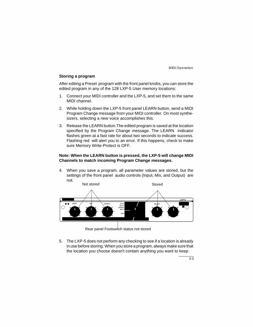
4. When you save a program, all parameter values are stored, but thesettings of the front panel audio controls (Input, Mix, and Output) arenot.
Not stored Stored
Rear panel Footswitch status not stored
BYPASS
SELECT
LXP-5
LEARN
exicon
EDIT
12345678
PRESET USERINPUT MIX OUTPUT
ABC
PITCHDELAY
CHORUSMULTI
5. The LXP-5 does not perform any checking to see if a location is alreadyin use before storing. When you store a program, always make sure thatthe location you choose doesn't contain anything you want to keep.

3-4
LXP-5 Owner's Manual
Living with controller quirksSome synthesizers and controllers cannot send the full range of MIDIprogram change messages (0-127). With them, you can't access all theregisters in the LXP-5. Others may appear to be able to send only 32, butactually have a bank mode that does let you send all 128 program changemessages. If in doubt, see the manual for your controller.
Patches and Dynamic MIDI
Some extremely useful effects can be created by controlling the LXP-5’svariable parameters remotely in real time. Almost all of the controllers foundon a MIDI keyboard or foot controller (pitch benders, mod wheels, sliders,switches, breath controllers, foot pedals and footswitches) can be used toadjust the LXP-5’s parameters. We refer to this real time remote controlcapability as Dynamic MIDI .
To use Dynamic MIDI , you patch a MIDI controller to the parameter youwant to control. You may patch a separate controller to each parameter, orpatch a single controller to control up to four parameters at once. Three typesof patches are used in the LXP-5: general purpose patches, an ADJUSTknob patch and global patches.
General Purpose PatchesFour general purpose patches are available in the LXP-5. These patchesuse a MIDI controller, a front panel knob or the low frequency oscillator (LFO)as sources to control one of the LXP-5 parameters, known as patchdestinations. A controller threshold is used along with a positive or negativescale factor to calculate offset. (Offset = [Source Value - Threshold] x ScaleFactor). The last calculated offset is stored with the patch so that, on recall,the parameter will have this value until the controller is moved. Four generalpurpose patches may be stored with any program by using the front panelcontrols or MIDI SysEx.

3-5
MIDI Operation
ADJUST Knob PatchThe front panel ADJUST knob can be assigned to as many as fiveparameters. This patch may be stored with a program in addition to the fourgeneral purpose patches. The usefulness and implementation of this patchis discussed in Chapter 2: Front Panel Operation: Choosing ADJUST knobdestination.
Global PatchesEach of the LXP-5’s 23 parameters can be patched directly to any singleMIDI controller. When a MIDI controller is specified as a global patch source,its value will be applied directly to the assigned parameter and will remainin effect regardless of what program is recalled. If a parameter which is theDestination of a global patch is also the Destination of the ADJUST knobpatch, the parameter value will be set to the latest value received fromwhichever controller or knob was moved last.
Creating a Dynamic MIDI PatchThere are three methods that can be used to create a patch. Some methodsdo not apply to all types of patches, and some are more convenient in certaininstances. The table below shows which methods can be used for ADJUSTknob, general purpose and global patches:
Patch Type Method of Creating a PatchEDIT MODE MIDI LEARN MIDI SYSEX
Adjust Knob X XGeneral Purpose X X X
Global X
Creating an ADJUST Knob Patch using Edit ModeRefer to Chapter 2: Front Panel Operation: Choosing ADJUST knobdestination.
3-6
LXP-5 Owner's Manual
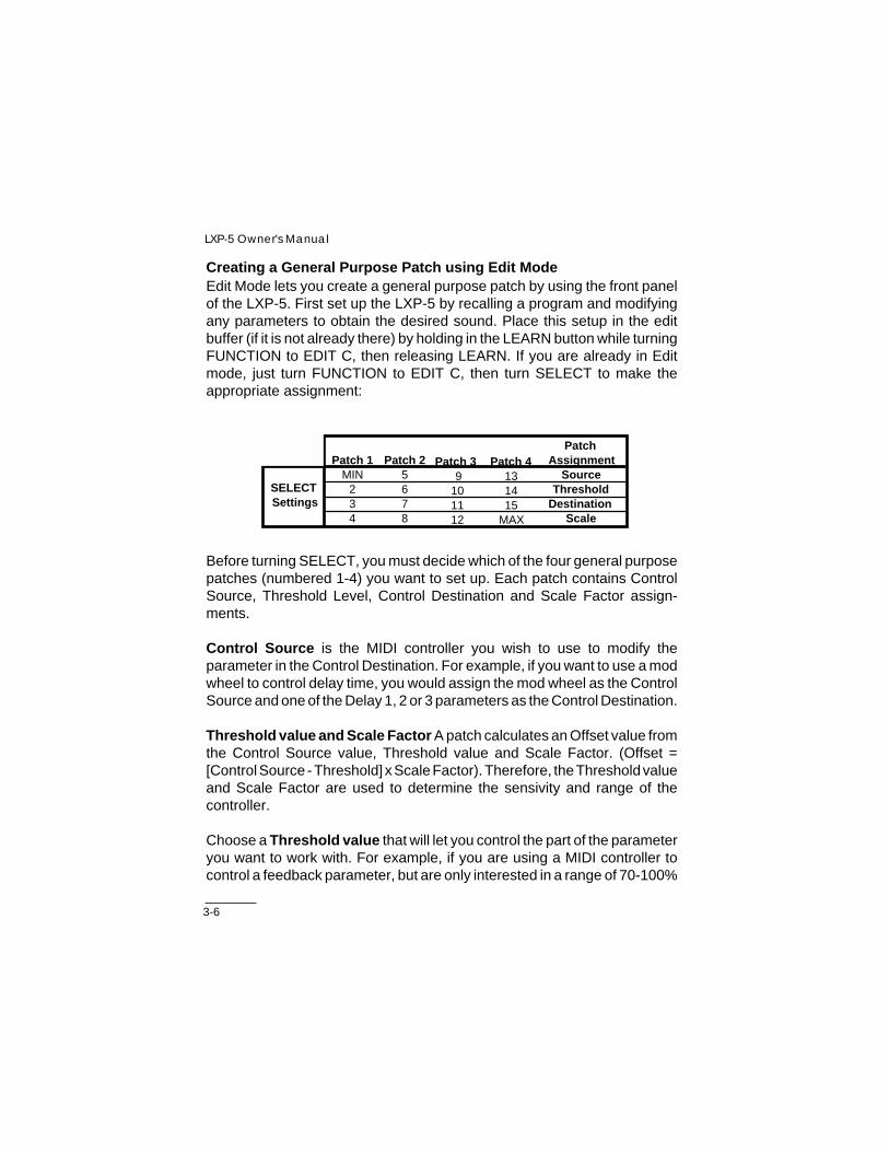
Creating a General Purpose Patch using Edit ModeEdit Mode lets you create a general purpose patch by using the front panelof the LXP-5. First set up the LXP-5 by recalling a program and modifyingany parameters to obtain the desired sound. Place this setup in the editbuffer (if it is not already there) by holding in the LEARN button while turningFUNCTION to EDIT C, then releasing LEARN. If you are already in Editmode, just turn FUNCTION to EDIT C, then turn SELECT to make theappropriate assignment:
Patch 4131415
MAX
SourceThreshold
DestinationScale
Patch 2 5678
Patch 1MIN
234
Patch 3 9
101112
SELECT Settings
Patch Assignment
Before turning SELECT, you must decide which of the four general purposepatches (numbered 1-4) you want to set up. Each patch contains ControlSource, Threshold Level, Control Destination and Scale Factor assign-ments.
Control Source is the MIDI controller you wish to use to modify theparameter in the Control Destination. For example, if you want to use a modwheel to control delay time, you would assign the mod wheel as the ControlSource and one of the Delay 1, 2 or 3 parameters as the Control Destination.
Threshold value and Scale Factor A patch calculates an Offset value fromthe Control Source value, Threshold value and Scale Factor. (Offset =[Control Source - Threshold] x Scale Factor). Therefore, the Threshold valueand Scale Factor are used to determine the sensivity and range of thecontroller.
Choose a Threshold value that will let you control the part of the parameteryou want to work with. For example, if you are using a MIDI controller tocontrol a feedback parameter, but are only interested in a range of 70-100%

3-7
MIDI Operation
feedback, you can set the threshold value high enough so the controller willbottom out at 70% and top out at 100%. Sixteen Threshold values from 0 to127 are available when using Edit mode to create a patch. If MIDI SysEx datais used to create a patch, any value from 0 to 127 may be used for Thresholdlevel.
Scale Factor defines the relationship between movement of the MIDIcontroller and the corresponding change it causes in the parameter setting.Choosing a low Scale Factor (under x1) will limit the range of control over theparameter. Choosing a high Scale Factor (x2) allows a controller with alimited range, such as a keyboard, to have access to most or all of theparameter values. A Scale Factor of x1 should give you access to the sameparameter values as the front panel ADJUST knob if a controller with a fullrange (0-127) is used. A positive Scale Factor will make the parameter valueincrease with an increasing controller value; a negative Scale Factor willmake the parameter value decrease with an increasing controller value.
The last calculated Offset value is stored with the patch so that, on recall ofthe program, the parameter will have this value until the controller is moved.
Once one of the four patches and its parameter is chosen by the SELECTknob, ADJUST may be used to assign Control Source, Control Destination,Threshold Level and Scale Factor:

3-8
LXP-5 Owner's Manual
Patch Assignments available via ADJUST
ADJUST CONTROLKnob Position SOURCE
MIN Patch Off2 Adjust Knob3 LFO Rate4 Last Note5 Low Note6 High Note7 Last Velocity8 Chnl Aftertouch9 MIDI Clock10 Mod Wheel11 Breath Control12 Foot Control13 Data Entry14 Volume15 Sustain Pedal
MAX Pitch Wheel
ADJUST THRESHOLDKnob Position LEVEL
MIN 02 83 174 255 346 427 518 599 6810 7611 8512 9313 10214 11015 119
MAX 127
ADJUST CONTROLKnob Position DESTINATION
MIN Delay 1 - Coarse2 Feedback 13 Delay 2 - Coarse4 Feedback 25 Delay 3 - Coarse6 Pitch Interval7 Decay Time8 Treble Decay9 Size*10 High Cut Filter11 Low Cut Filter12 Reverb Balance13 Input Level14 Output Level15 Output Balance
MAX LFO Rate
ADJUST SCALEKnob Position FACTOR
MIN x(-2.0)2 x(-1.0)3 x(-0.8)4 x(-0.6)5 x(-0.4)6 x(-0.3)7 x(-0.2)8 x(-0.1)9 x 0.110 x 0.211 x 0.312 x 0.413 x 0.614 x 0.815 x 1.0
MAX x 2.0
Altering the Size parameter in real-time will cause the LXP-5 to mute briefly.
3-9
MIDI Operation
After a patch is created, it can be saved in a register. Up to four generalpurpose patches may be created and saved in each memory location.
Creating a General Purpose Patch using MIDI Learn ModeThis method of creating a patch is fairly simple but it limits you to one activegeneral purpose patch at a time. To create a patch:
1. First set up the LXP-5 for the desired sound by recalling a program, orby creating a new sound. (If ADJUST is already patched to the desiredparameter, skip to Step 4.)
2. Put the LXP-5 into Edit mode by holding in the LEARN button and turningFUNCTION to EDIT B. Release the LEARN button.
3. Turn FUNCTION and SELECT so that the desired parameter is beingedited by ADJUST.
4. Using a standard MIDI cable, connect LXP-5 MIDI IN to the MIDI OUTport of the controller you wish to use.
5. Press and hold in the LEARN button while moving the MIDI controlleryou want to patch. You don’t have to move the controller through itsentire range — just move it enough for the LXP-5 to identify whatcontroller you are using. For example, if you are patching a mod wheelon a keyboard, move the mod wheel slightly.
6. Continue to hold the LEARN button in while turning ADJUST to set thescale factor. This will set the controller’s range of effectiveness. Position8 corresponds to zero scale, MIN corresponds to full negative scale;MAX corresponds to full positive scale. The ADJUST knob must bemoved at least one click to record a scale factor.

3-10
LXP-5 Owner's Manual
7. Release the LEARN button. The position of the ADJUST knob at themoment the LEARN button is released will be used to determine thescale factor. If you moved more than one MIDI controller while holdingin the LEARN button, the last one moved will be used. Note: if the LXP-5 was in Edit mode while setting up the patch, the last parameterassigned will be used as the Control Destination.
8. Set ADJUST to the desired base parameter value. This will be theparameter value when the Control Source is zero. If you want access tothe full range of parameter adjustment, set ADJUST to MIN.
The MIDI controller will now be patched to the desired parameter, and youcan store this patch with the program if you like.
This patch can be cleared by holding in the LEARN button, turning theADJUST knob (without operating a MIDI controller), then releasing theLEARN button.
Notes:
• If FUNCTION or SELECT is moved while the LEARN button is pressed,the patch will not be created and the new setup will be loaded immediately.
• This general purpose patch will be saved as Patch 1, overwriting anyexisting Patch 1 information; other patches will not be affected.
• A controller key press (Note On) is interpreted as Note Velocity for theControl Source.
• A controller key release (Note Off, or Velocity zero) which is not precededby any aftertouch messages is interpreted as Note Number for the ControlSource.
• Aftertouch messages, followed by an optional Note Off, are interpreted asAftertouch for the Control Source.
• One or more MIDI clocks present while the LEARN button is pressed isinterpreted as MIDI Tempo Period as the Control Source. This is true evenif other controller messages are sent while pressing the LEARN button.Therefore, no MIDI clocks should be present when clearing a patch.

3-11
MIDI Operation
Using programmable controllers
When you patch a MIDI controller to an LXP-5 parameter, you don't need toworry about which controller code is sent by the particular controller. Whenyou move the controller during patch assignment, the LXP-5 examines theincoming data, and automatically sets itself to match the controller you aremoving.
Some MIDI units allow you to assign any controller code you like to theirfootpedals, footswitches, and other programmable switches and sliders.From the LXP-5's point of view, it doesn't matter what controller code youassign — it responds correctly to anything you send it. However, if there areother devices in your system on the same MIDI channel, you shouldassign a controller number that is not used on the other devices.
Creating Patches using MIDI SysEx
Patches can also be created using LXP-5 MIDI System Exclusive data. Thisis perhaps the most complicated but also the most flexible way of creatingpatches to control the LXP-5.
A device that is programmed to transmit LXP-5 SysEx data is needed, suchas the Lexicon MRC MIDI Remote Controller (with Rev. 3.0 or highersoftware). The MRC allows you to edit up to eight parameters for eachprogram giving you much greater creative potential. Programs can be storedin the MRC, making it a powerful control center for systems that include oneor more LXP-1s and/or LXP-5s. Many of these functions may also beavailable in software packages for popular personal computer systems. Seeyour Lexicon dealer for details.
Chapter 4 provides the information necessary for programming LXP-5 MIDISysEx data.

3-12
LXP-5 Owner's Manual
Assigning Switches as Control Sources
In addition to continuous controllers, you can patch switches and use themto choose between two parameter values.
The LFO Control SourceThe LXP-5 contains a low frequency oscillator (LFO). Its output can be usedas a Control Source with any parameter. The output of the LFO is a sinusoidwith peak values from 0 to 127, and a rate adjustable from 0.066 Hz to 5 Hz.
Feel free to experiment with parameters to determine which you find areuseful with the LFO as their Control Source.
Using MIDI Clock as a Control SourceMIDI tempo period patches may be made by using a MIDI clock as a ControlSource for one of the LXP-5’s delay parameters. This gives you the abilityto make sync delay setups where delay times are related to LXP-5 delayparameters. Under these circumstances the following conditions will apply:
1. The delay time is not dependent upon the base parameter value. Onlythe MIDI tempo period and patch information will affect it.
2. In order to preserve an acceptable rhythmic relationship, when thecalculated delay value exceeds the maximum delay value permissibleby the LXP-5, it will be repeatedly cut in half until it is within the stateddelay parameter range.
3. When enabling a patch from MIDI LEARN Mode, the MIDI patch scaleis related to the effective note duration of the delay as shown in thefollowing table:

3-13
MIDI Operation
Disabling a Global PatchGlobal patches can be disabled from the front panel of the LXP-5. To do this,simply turn FUNCTION to EDIT A, turn SELECT to position MAX, and setADJUST according to the following table:
ADJUST GLOBAL PATCHKnob Position EDIT
MIN - 6 Disables all global patches7 - 11 Re-enables a global patch after
moving associated MIDI controller12 - MAX Re-enables all global patches immediately
ADJUST NOTE SCALEKnob Position DURATION VALUE
MIN Half Note 02 Dotted Quarter 13 Half Triplet 24 Quarter Note 35 Dotted Eighth 46 Quarter Triplet 57 Eighth Note 68 Dotted Sixteenth 79 Eighth Triplet 810 Sixteenth 911 Sixteenth Triplet 1012 Thirty-second 11
This feature can only disable and re-enable all existing global patches. Itcannot be used to create new global patches.
Note: The global patch sources for parameters 0-22 are intitialized atthe factory to correspond to MIDI controllers 8-30. The LXP-5 isshipped with global patches disabled.
4-1
MIDI Implementation Data
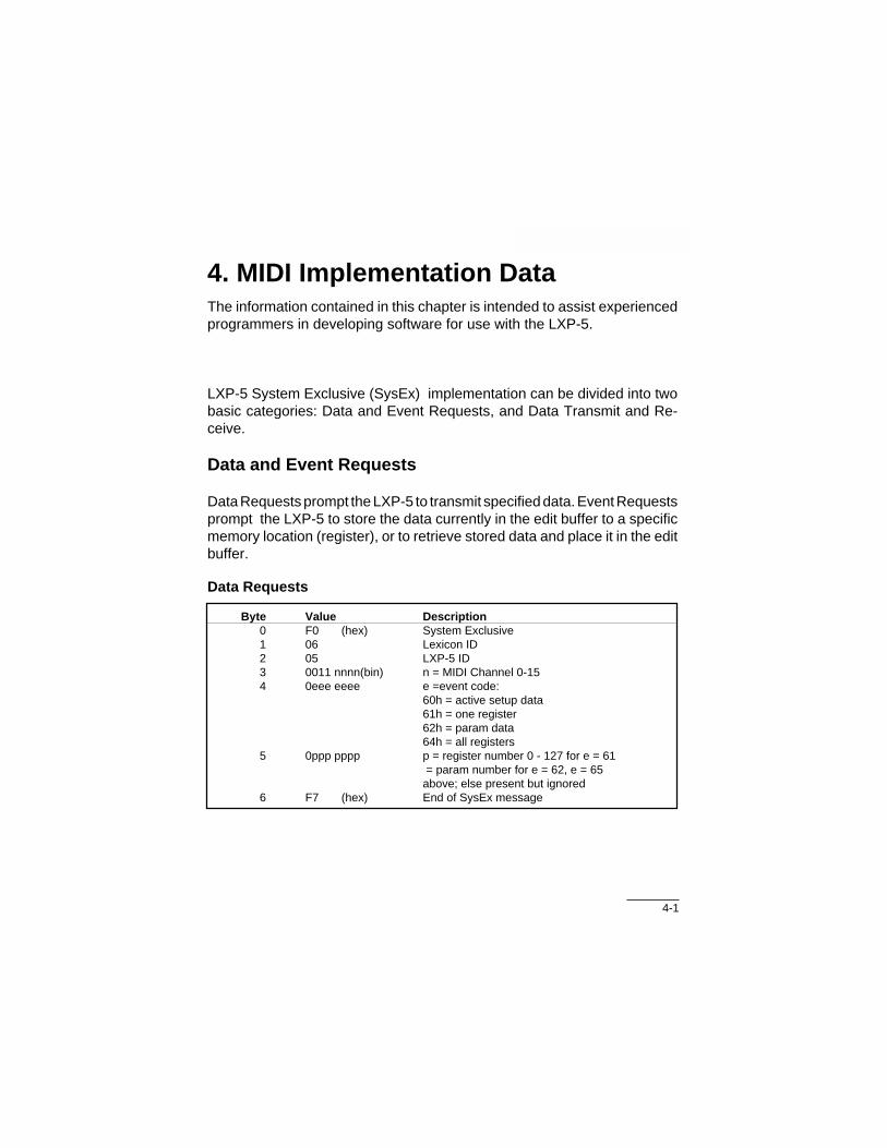
4. MIDI Implementation DataThe information contained in this chapter is intended to assist experiencedprogrammers in developing software for use with the LXP-5.
LXP-5 System Exclusive (SysEx) implementation can be divided into twobasic categories: Data and Event Requests, and Data Transmit and Re-ceive.
Data and Event Requests
Data Requests prompt the LXP-5 to transmit specified data. Event Requestsprompt the LXP-5 to store the data currently in the edit buffer to a specificmemory location (register), or to retrieve stored data and place it in the editbuffer.
Data Requests
Byte Value Description0 F0 (hex) System Exclusive1 06 Lexicon ID2 05 LXP-5 ID3 0011 nnnn(bin) n = MIDI Channel 0-154 0eee eeee e =event code:
60h = active setup data61h = one register62h = param data64h = all registers
5 0ppp pppp p = register number 0 - 127 for e = 61 = param number for e = 62, e = 65above; else present but ignored
6 F7 (hex) End of SysEx message

4-2
LXP-5 Owner's Manual
Event Requests
Byte Value Description0 F0 (hex) System Exclusive1 06 Lexicon ID2 05 LXP-5 ID3 0110 nnnn(bin) n = MIDI Channel 0-154 0eee eeee e = event code:
70h = store current edit to register71h = recall program to edit buffer
5 0ppp pppp p = register number 0 - 1276 F7 (hex) End of SysEx message
Transmit/Receive Data
Data is identical in format whether transmitted as a response to a DataRequest or received as a Data Dump.
When the front panel ADJUST knob is assigned to a parameter and turned,the LXP-5 will transmit a parameter change message reflecting the newposition of the knob (SeeParameter Adjust for the format.). The transmittedparameter number will reflect the specific parameter to which the knob isassigned. Changing a parameter in Edit mode will also cause a parameterchange mesage to be sent. Recalling a program with the front panelFUNCTION or ADJUST knobs will cause the appropriate program parame-ter change message to be sent.
Two LXP-5s can be slaved together by connecting a cable from the MIDIOUT jack of the master to the MIDI IN jack of the slave. Additional LXP-5scan be slaved to the same master by connecting a cable from the MIDI THRUport of one unit to the MIDI IN port of the next unit.
Remember, since one jack serves as both MIDI THRU and MIDI OUT on theLXP-5, be sure the rear panel switch is in the appropriate position.
All LXP-5s must be set to the same MIDI Channel.

4-3
MIDI Implementation Data
Active Setup Data
Byte Value Description0 F0 (hex) System Exclusive1 06 Lexicon ID2 05 LXP-5 ID3 0000 nnnn(bin) n = MIDI Channel 0-154 5E (hex) data byte count (94)5 0vvv vvvv(bin) 7-bit data
.
.
.98 0vvv vvvv99 0sss ssss sumcheck of data bytes
100 F7 (hex) End of SysEx message
Stored (Single Program) Data
Byte Value Description0 F0 (hex) System Exclusive1 06 Lexicon ID2 05 LXP-5 ID3 0001 nnnn(bin) n = MIDI Channel 0-154 0ppp pppp p = register number 0 - 1275 39 (hex) data byte count (57)6 0vvv vvvv 7-bit data
.
.
.62 0vvv vvvv63 0sss ssss sumcheck of data bytes64 F7 (hex) End of SysEx message
4-4
LXP-5 Owner's Manual
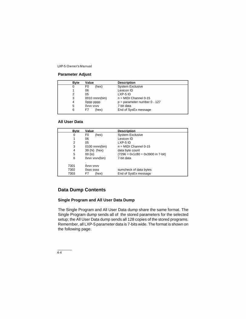
Parameter Adjust
Byte Value Description0 F0 (hex) System Exclusive1 06 Lexicon ID2 05 LXP-5 ID3 0010 nnnn(bin) n = MIDI Channel 0-154 0ppp pppp p = parameter number 0 - 1275 0vvv vvvv 7-bit data6 F7 (hex) End of SysEx message
All User Data
Byte Value Description0 F0 (hex) System Exclusive1 06 Lexicon ID2 05 LXP-5 ID3 0100 nnnn(bin) n = MIDI Channel 0-154 39 (hi) (hex) data byte count5 00 (lo) (7296 = 0x1c80 = 0x3900 in 7-bit)6 0vvv vvvv(bin) 7-bit data
.7301 0vvv vvvv7302 0sss ssss sumcheck of data bytes7303 F7 (hex) End of SysEx message
Data Dump Contents
Single Program and All User Data Dump
The Single Program and All User Data dump share the same format. TheSingle Program dump sends all of the stored parameters for the selectedsetup; the All User Data dump sends all 128 copies of the stored programs.Remember, all LXP-5 parameter data is 7-bits wide. The format is shown onthe following page.

4-5
MIDI Implementation Data
Data Byte # Data Param # Data Description0 66 Program (Algorithm) ID
1 - 23 0 -22 Microcode Parameters24 - 34 31 - 41 Name (11 characters)
35 42 Reserved36 43 Knob Patch Destination
37 - 41 44 - 48 General Purpose Patch 1 Parameters42 - 46 49 - 53 General Purpose Patch 2 Parameters47 - 51 54 - 58 General Purpose Patch 3 Parameters52 - 56 59 - 63 General Purpose Patch 4 Parameters
Active Setup Dump
The Active Setup data dump sends all the parameters for the current setupas well as the global parameters. The format is:
Data Byte # Data Param # Data Description0 66 Program (Algorithm) ID
1 - 23 0 - 22 Microcode Parameters24 - 31 23 - 30 Knob Mechanism Parameters32 - 42 31 - 41 Name (11 characters)
43 42 Reserved44 43 Knob Patch Destination
45 - 49 44 - 48 General Purpose Patch 1 Parameters50 - 54 49 - 53 General Purpose Patch 2 Parameters55 - 59 54 - 58 General Purpose Patch 3 Parameters60 - 64 59 - 63 General Purpose Patch 4 Parameters
65 64 Register Number66 65 Preset Number67 66 Program (Algorithm) ID68 67 Footswitch mode69 68 Memory Write Protect70 69 Global Patch Enable
71 - 93 70 - 90 Global Patch Sources
4-6
LXP-5 Owner's Manual
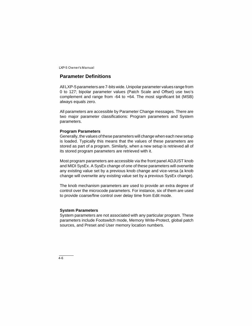
Parameter Definitions
All LXP-5 parameters are 7-bits wide. Unipolar parameter values range from0 to 127; bipolar parameter values (Patch Scale and Offset) use two’scomplement and range from -64 to +64. The most significant bit (MSB)always equals zero.
All parameters are accessible by Parameter Change messages. There aretwo major parameter classifications: Program parameters and Systemparameters.
Program ParametersGenerally, the values of these parameters will change when each new setupis loaded. Typically this means that the values of these parameters arestored as part of a program. Similarly, when a new setup is retrieved all ofits stored program parameters are retrieved with it.
Most program parameters are accessible via the front panel ADJUST knoband MIDI SysEx. A SysEx change of one of these parameters will overwriteany existing value set by a previous knob change and vice-versa (a knobchange will overwrite any existing value set by a previous SysEx change).
The knob mechanism parameters are used to provide an extra degree ofcontrol over the microcode parameters. For instance, six of them are usedto provide coarse/fine control over delay time from Edit mode.
System ParametersSystem parameters are not associated with any particular program. Theseparameters include Footswitch mode, Memory Write-Protect, global patchsources, and Preset and User memory location numbers.

4-7
MIDI Implementation Data
Parameter Map
Param # Data0 - 22 Microcode Parameters
23 - 30* Knob Mechanism Parameters31 - 41 Name (11 characters)
42 Reserved43 Adjust Knob Patch Destination (microcode param # 0 - 22)
44 - 48 MIDI General Purpose Patch 1 (see below)49 - 53 MIDI General Purpose Patch 2 (see below)54 - 58 MIDI General Purpose Patch 3 (see below)59 - 63 MIDI General Purpose Patch 4 (see below)
64* Memory location (0 - 127)65* Preset # (0 - 65; 0-63=Preset Table, 64=Bypass,
65=Edit buffer, 127=Memory location)66 Algorithm ID (1 - 3; 1=Delay/Reverb, 2=Pitch/Delay, 3=Bypass)67* Footswitch Mode (0 - 127; 0 & 4-127=Defeat Input, 1=Defeat Output,
2=Bypass, 3=Memory Increment)68* Memory Write Protect (nonzero = write protected)69 Global Patch Enable (0=global patches disabled, 1=global patches
ignored on setup recall until Source controller is moved,2=global patches active immediately on setup recall
70 - 92* MIDI Global Patch Sources
*Not stored during program save.
General Purpose Patch Parameter Map:
Param #Patch 1 Patch 2 Patch 3 Patch 4 Data
44 49 54 59 Patch Source(0 - 127, see below)
45 50 55 60 Patch Threshold(0 - 127)
46 51 56 61 Patch Destination(microcode param # 0-22)
47 52 57 62 Patch Scale Factor(-64 to +64, 2’s complem.)
48 53 58 63 Patch Offset

4-8
LXP-5 Owner's Manual
MIDI Patch Sources (General Purpose and Global):
Control # Function0 - 31 Continuous controller 0 - 3132 - 63 Switches 0 - 31
64 Last note played65 Last note’s velocity66 Channel aftertouch value67 Pitch bend value68 MIDI tempo period69 Front panel Adjust knob70 LFO value71 Lowest note held72 Highest note held
Global patch parameter numbers 70-92 correspond to microcode parame-ter numbers 0-22. Therefore, if you want to globally patch the front panelADJUST knob to decay time (microcode parameter 11) you would use theglobal patch parameter number of 81 (70+11). Its data value would be 69,corresponding to the ADJUST knob control number.
The MIDI patch Offset values are generated internally by the equation:Offset = [Source-Threshold] x Scale Factor
where Source equals the value of the specified controller.
This calculated Offset value is added to the stored (base) value of thespecified destination parameter. The sum of the offset and base values is thenumber used by the audio processor and the parameter transmit routines.The programmer should be aware that the offset values are internallyupdated continuously — therefore if the programmer changes the offsetvalue externally it will be over-written shortly thereafter. The offset param-eters are most useful when read to determine the MIDI patch contribution tothe parameter values transmitted by the LXP-5.
NOTE: When the LXP-5 receives a parameter change, the received valueis used as the new base parameter value. However, when the LXP-5transmits a parameter value, this value equals the sum of the baseparameter value and any applicable MIDI patch offsets.
4-9
MIDI Implementation Data
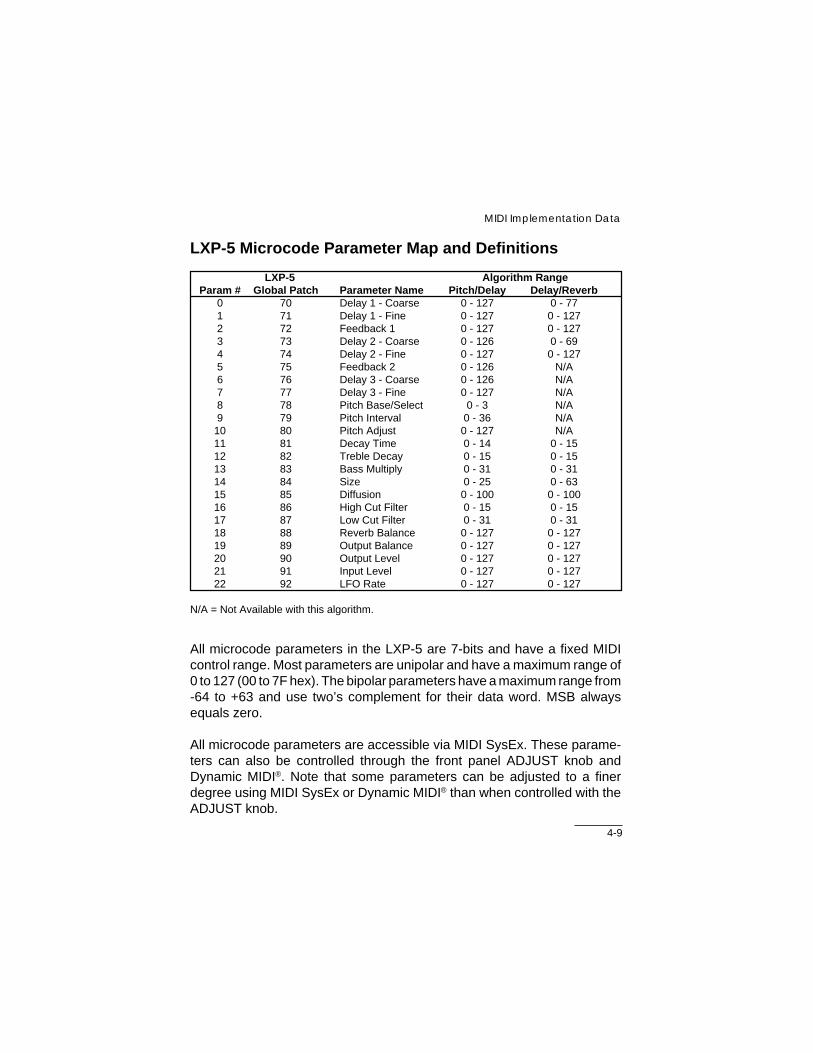
LXP-5 Microcode Parameter Map and Definitions
LXP-5 Algorithm RangeParam # Global Patch Parameter Name Pitch/Delay Delay/Reverb
0 70 Delay 1 - Coarse 0 - 127 0 - 771 71 Delay 1 - Fine 0 - 127 0 - 1272 72 Feedback 1 0 - 127 0 - 1273 73 Delay 2 - Coarse 0 - 126 0 - 694 74 Delay 2 - Fine 0 - 127 0 - 1275 75 Feedback 2 0 - 126 N/A6 76 Delay 3 - Coarse 0 - 126 N/A7 77 Delay 3 - Fine 0 - 127 N/A8 78 Pitch Base/Select 0 - 3 N/A9 79 Pitch Interval 0 - 36 N/A
10 80 Pitch Adjust 0 - 127 N/A11 81 Decay Time 0 - 14 0 - 1512 82 Treble Decay 0 - 15 0 - 1513 83 Bass Multiply 0 - 31 0 - 3114 84 Size 0 - 25 0 - 6315 85 Diffusion 0 - 100 0 - 10016 86 High Cut Filter 0 - 15 0 - 1517 87 Low Cut Filter 0 - 31 0 - 3118 88 Reverb Balance 0 - 127 0 - 12719 89 Output Balance 0 - 127 0 - 12720 90 Output Level 0 - 127 0 - 12721 91 Input Level 0 - 127 0 - 12722 92 LFO Rate 0 - 127 0 - 127
N/A = Not Available with this algorithm.
All microcode parameters in the LXP-5 are 7-bits and have a fixed MIDIcontrol range. Most parameters are unipolar and have a maximum range of0 to 127 (00 to 7F hex). The bipolar parameters have a maximum range from-64 to +63 and use two’s complement for their data word. MSB alwaysequals zero.
All microcode parameters are accessible via MIDI SysEx. These parame-ters can also be controlled through the front panel ADJUST knob andDynamic MIDI®. Note that some parameters can be adjusted to a finerdegree using MIDI SysEx or Dynamic MIDI® than when controlled with theADJUST knob.

4-10
LXP-5 Owner's Manual
Knob Mechanism Parameters
27 Delay 1 Fine Edit Knob28 Reserved29 Delay 2 Coarse Edit Knob30 Delay 2 Fine Edit Knob
Param # Description23 Delay 0 Coarse Edit Knob24 Delay 0 Fine Edit Knob25 Reserved26 Delay 1 Coarse Edit Knob
Delay Parameters
Parameter # Range: Increment ResolutionPitch/Delay Delay/Reverb
Delay 1 - Coarse 0 0 - 1.0404 sec 0 - 630.8 msec ≈ 8.2 msec 128 steps P/D78 steps D/R
Provides a coarse adjustment of mono delay time.
Delay 1 - Fine 1 0 - 8.1 msec 0 - 8.1 msec 64 usec 128 stepsFunction: Provides a fine adjustment of mono delay time by adding to the Delay 1-Coarsevalue.
Feedback 1 2 0 - 100% 0 - 100% ≈ 0.79% 128 stepsAdjusts positive feedback around the mono delay. In Pitch/Delay, 100% feedback automati-cally cuts the input, and can be used as a manual, or MIDI controlled, delay line sampler. InDelay/Reverb, 100% feedback does not cut the input, but continues to add it in. There is alsoa slight high frequency rolloff through the gliding delay mechanism of Delay/Reverb-Delay 1.
Delay 2 - Coarse 3 0 - 322.5 msec 0 - 176.6 msec 2.56 msec 127 steps P/D70 steps D/R
Provides a coarse adjustment of two-channel delay time.In Delay/Reverb, provides a pre-delay adjustment for the reverb. In Pitch/Delay provides a reverb pre-delay and adjusts theright channel.
Delay 2 - Fine 4 0 - 2.5 msec 0 - 2.5 msec ≈ 20 usec 128 stepsProvides a fine adjustment of right channel delay time by adding to the Delay 2-Coarse value.
Feedback 2 5 0 - 99% NA ≈ 0.79% 127 stepsAdjusts feedback around the pitch shifter and left channel delay.
Delay 3 - Coarse 6 0 - 322.5 msec NA 2.56 msec 127 stepsProvides a coarse adjustment for left channel delay.
Delay 3 - Fine 7 0 - 2.5 msec NA ≈. 20 usec 128 stepsProvides a fine adjustment for left channel delay by adding to the Delay 3-Coarse value.
4-11
MIDI Implementation Data
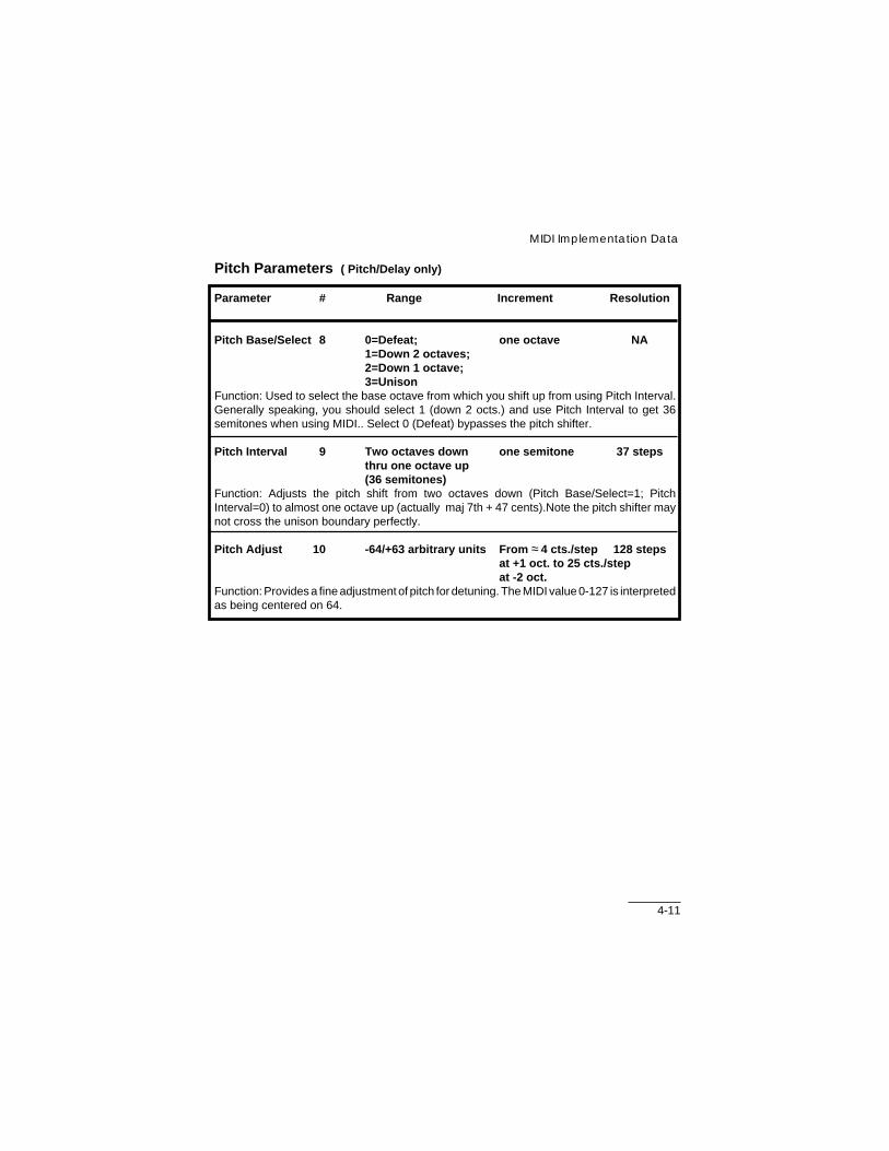
Pitch Parameters ( Pitch/Delay only)
Parameter # Range Increment Resolution
Pitch Base/Select 8 0=Defeat; one octave NA1=Down 2 octaves;2=Down 1 octave;3=Unison
Function: Used to select the base octave from which you shift up from using Pitch Interval.Generally speaking, you should select 1 (down 2 octs.) and use Pitch Interval to get 36semitones when using MIDI.. Select 0 (Defeat) bypasses the pitch shifter.
Pitch Interval 9 Two octaves down one semitone 37 stepsthru one octave up(36 semitones)
Function: Adjusts the pitch shift from two octaves down (Pitch Base/Select=1; PitchInterval=0) to almost one octave up (actually maj 7th + 47 cents).Note the pitch shifter maynot cross the unison boundary perfectly.
Pitch Adjust 10 -64/+63 arbitrary units From ≈ 4 cts./step 128 stepsat +1 oct. to 25 cts./stepat -2 oct.
Function: Provides a fine adjustment of pitch for detuning. The MIDI value 0-127 is interpretedas being centered on 64.

4-12
LXP-5 Owner's Manual
Reverb Parameters
Parameter # Range: Increment ResolutionPitch/Delay Delay/Reverb
Decay Time 11 0.5-12 seconds 0.5 sec.-infinity varies 15 steps P/Dmin. is 0.1 sec. 16 steps D/R
Function: Adjusts mid reverb time. Infinite reverb is available in Delay/ Reverb algorithm only.
Treble Decay 12 320 Hz 320 Hz logarithmic 16 stepsto full range to full range
Function: Provides an adjustment of the low pass filter within the reverb. Maximum settinggives a flat response through the filter section.
Bass Multiply 13 x0.3 to x2.5 x0.3 to x2.5 linear 32 stepsFunction: Provides control over bass reverb time.
Size 14 8 - 26 meters 8 - 53.5 meters linear 26 steps P/D64 steps D/R
Function: Adjusts the room size. The range is for one side of a room; cube these values toget the approximate room volume.
Diffusion 15 0 - 100% 0 - 100% 1% 101 stepsFunction: Softens the attack of percussive sounds in the reverberator.
Equalization Parameters
Parameter # Range: Increment ResolutionPitch/Delay Delay/Reverb
High Cut Filter 16 320 Hz 320 Hz logarithmic 16 steps to full range to full range
Function: Provides adjustment of high frequency roll-off. Maximum setting gives flat responsethrough the filter section.
Low Cut Filter 17 Full range Full range logarithmic 32 steps to 1350 Hz to 1350 Hz
Function: Provides adjustment of low frequency roll-off. Minimum setting gives flat responsethrough the filter section.

4-13
MIDI Implementation Data
Level Parameters
Note: The Reverb Balance and Output Balance parameters each act like aconventional pan circuit with a 3 dB loss when set to a 50/50 mix. To insurethe best signal to noise ratio, the Output Level parameter includes 6 dB ofgain to offset these losses. As a result, however, the panning will be verysharp when the Output Level is set at maximum (100%). A smoother pan canbe achieved by reducing the Output Level 3 dB (about 70%).
Parameter # Range: Increment ResolutionPitch/Delay Delay/Reverb
Reverb Balance 18 100% effects/ 100% effects/ Follows sine/ 128 steps0% reverb to 0% reverb to cosine curves0% effects/ 0% effects/
100% reverb 100% reverbFunction: Adjusts the mix of reverb with delay effects.
Output Balance 19 100% left 100% left Follows sine/ 128 steps to 100% right to 100% right cosine curves
Function: Provides a pan control for the wet output.
Output Level 20 0 - 100% 0 - 100% ≈ 0.79% 128 stepsFunction: Adjusts the output level of the signal processor.
Input Level 21 0 - 100% 0 - 100% ≈ 0.79% 128 stepsFunction: Adjusts the input level to the signal processor.
LFO Rate 22 0.066 - 10 Hz 0.066 - 10 Hz logarithmic 128 stepsapproximation
Function: Adjusts the frequency of the low frequency oscillator.

4-14
LXP-5 Owner's Manual
Mode 1: OMNI ON, POLY Mode 2: OMNI ON, MONOMode 3: OMNI OFF, POLY Mode 4: OMNI OFF, MONO
O : YesX : No
Version: 1.0
MIDI Implementation Chart
Lexicon LXP-5Effects Processing Module
Function Transmitted Recognized Remarks
Basic Default 1 1Channel Channel 1-16 1-16 Memorized
Mode DefaulltMessages Mode 3Altered
Note X 0 - 127 Used asNumber True Voice controller
Velocity Note ON X ONote OFF X X
After Keys X XTouch Channels X O
Pitch Bender X O
Control X 0 - 127Change
Program X 0 - 127Change True # 0 - 127
System Exclusive O O
System :Song Pos X X:Song Sel X X
Common :Tune X X
System :Clock X O Used asReal Time :Commands X X controller
Aux :Local ON/OFF X XMessages :All Notes OFF X X
:Active Sense X X:Reset X O
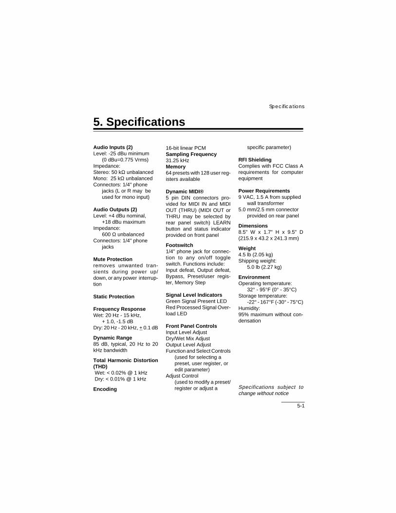
5-1
Specifications
5. Specifications
Audio Inputs (2)Level: -25 dBu minimum
(0 dBu=0.775 Vrms)Impedance:Stereo: 50 kΩ unbalancedMono: 25 kΩ unbalancedConnectors: 1/4" phone
jacks (L or R may beused for mono input)
Audio Outputs (2)Level: +4 dBu nominal,
+18 dBu maximumImpedance:
600 Ω unbalancedConnectors: 1/4" phone
jacks
Mute Protectionremoves unwanted tran-sients during power up/down, or any power interrup-tion
Static Protection
Frequency ResponseWet: 20 Hz - 15 kHz,
+ 1.0, -1.5 dBDry: 20 Hz - 20 kHz, + 0.1 dB
Dynamic Range85 dB, typical, 20 Hz to 20kHz bandwidth
Total Harmonic Distortion(THD) Wet: < 0.02% @ 1 kHz Dry: < 0.01% @ 1 kHz
Encoding
specific parameter)
RFI ShieldingComplies with FCC Class Arequirements for computerequipment
Power Requirements9 VAC, 1.5 A from supplied
wall transformer5.0 mm/2.5 mm connector
provided on rear panel
Dimensions8.5" W x 1.7" H x 9.5" D(215.9 x 43.2 x 241.3 mm)
Weight4.5 lb (2.05 kg)Shipping weight:
5.0 lb (2.27 kg)
EnvironmentOperating temperature:
32° - 95°F (0° - 35°C)Storage temperature:
-22° - 167°F (-30° - 75°C)Humidity:95% maximum without con-densation
Specifications subject tochange without notice
16-bit linear PCMSampling Frequency31.25 kHzMemory64 presets with 128 user reg-isters available
Dynamic MIDI®5 pin DIN connectors pro-vided for MIDI IN and MIDIOUT (THRU) (MIDI OUT orTHRU may be selected byrear panel switch) LEARNbutton and status indicatorprovided on front panel
Footswitch1/4" phone jack for connec-tion to any on/off toggleswitch. Functions include:Input defeat, Output defeat,Bypass, Preset/user regis-ter, Memory Step
Signal Level IndicatorsGreen Signal Present LEDRed Processed Signal Over-load LED
Front Panel ControlsInput Level AdjustDry/Wet Mix AdjustOutput Level AdjustFunction and Select Controls
(used for selecting apreset, user register, oredit parameter)
Adjust Control(used to modify a preset/register or adjust a

User Memory Record of Contents
This page may be copied as needed for documenting the sounds stored inLXP-5 User memory.
USER BANK #
SELECTKnob Position Name
MIN 23456789101112131415
MAX
1 2 3 4 5 6 7 8
#PROGRAMS
Lexicon Part No. 070-07332 Rev 1 Printed in U.S.A.
Lexicon, Inc.3 Oak ParkBedford, MA 01730 USATelephone 781-280-0300Fax 781-280-0490