
Owner's Manual 10 in. Stationary -...
64
Owner's Manual 10 in. Stationary TABLE SAW Model No. 315.228310 Save this manual for future reference _, CAUTION: Read and follow all Safety Rules and Operating Instructions before first use of this product. ".I Customer Help Line: 1-800-932-3188 Sears, Roebuck and Co., Hoffman Estates, IL 60179 USA Visit the Craftsman web page: www.sears.com/craftsman 972000-524 10-98 • Safety • Features • Assembly • Operation • Maintenance • Parts List NRTL/C
Transcript of Owner's Manual 10 in. Stationary -...

Owner's Manual
10 in. StationaryTABLE SAW
Model No.315.228310
Save this manual forfuture reference
_, CAUTION: Read and follow allSafety Rules and OperatingInstructions before first use of thisproduct.
".I
Customer Help Line: 1-800-932-3188
Sears, Roebuck and Co., Hoffman Estates, IL 60179 USA
Visit the Craftsman web page: www.sears.com/craftsman
972000-52410-98
• Safety• Features• Assembly• Operation• Maintenance• Parts List
NRTL/C
FULLONEYEARWARRANTYONCRAFTSMANTABLESAW
If thisrRRFTSMRN Table Saw failsdue to a defect in material or workmanshipwithinone year fromthe date ofpurchase. Sears will repair it, free of charge,
Contact a Sears Service Center for repair.
If this productis used forcommercialor rental purposes,this warranty appliesonly for 90 days fromthe date ofpurchase.
This warranty gives you specificlegal dghts,and you may also have other rightswhich vary from state to state.
Sears, Roebuck and Co., Dept. 81"IWA, Hoffman Estates, IL 60179
Your saw has many features for making cuttingoperationsmore pleasant and enjoyable. Safety, performanceand dependabilityhave been given top priority inthe design of thissaw making it easy to maintainand operate.
_, CAUTION: Carefully read throughthis entire owner's manual before usingyour new saw. Pay closeattentionto the Rules For Safe Operation and all Safety Alert Symbols, includingDanger, Wam ng andCaution. If you use your saw properlyand only for what it is intended,you will enjoy years of safe, reliableservice.
._ Look for thissymbol to point out importantsafety precautions.It means attention!!!Your safetyis involved.
WARNING:
The operationof any power tool can resultin foreign objects beingthrowninto your eyes,which can result in severe eye damage. Before beginningpower tool operation, alwayswear safety goggles or safety glasses with side shieldsand a full face shieldwhen needed.We recommenda Wide Vision Safety Mask for use over eyeglasses or standardsafetyglasses withside shields, available at Sears Retail Stores.
• Warranty and Introduction.............................................................................................................................. 2
• Table Of Contents ....................................................................................................................................... 2-3
• Rules For Safe Operation ........................................................................................................................... 4-6
• Electrical ......................................................................................................................................................... 7
• Glossary and ProductSpecifications............................................................................................................. 8
• Unpackingand Accessories........................................................................................................................... 9
• Loose Parts List...................................................................................................... ...................................... 10
• Small Parts List ....................................................................................................................................... 11-12
• Tools Needed ............................................................................................................................................... 13
• Labels ...................................................................................................................................................... 14-15
• Features .................................................................................................................................................. 16-17
• Assembly ................................................................................................................................................. 18-27
InstallingHandwheels on Table Saw Base .................................................................................................. 18AssemblingLeg Stand ............................................................................................................................ 18-19
CRAFTSMAN"TABLESAW315.228310 2
MountingtheLegStandontheTableSawBase........................................................................................ 19AssemblingTable Extensions...................................................................................................................... 20AligningTable Extensions ............................................................................................................................ 20
Installingthe Rear Rail ................................................................................................................................. 21Installingthe Front Rail ................................................................................................................................ 22
AligningRip Fence and Front Rail ............................................................................................................... 23Mountingthe Motor ...................................................................................................................................... 23Installingthe Belt and Belt Guard ................................................................................................................ 24Checkingthe Throat Plate ............................................................................................................................ 24
Installingthe Blade Guard ............................................................................................................................ 25Aligningthe Riving Knife with the Blade ...................................................................................................... 26Checking Rip Fence and Blade Alignment .................................................................................................. 27
• Adjustments............................................................................................................................................. 28-32Replacingthe Blade ..................................................................................................................................... 28
Heeling (Paralleling) the Sawblade to Miter Gage Groove ........................................ t............................ 29-30Setting the Bevel Stops and Indicator..................................................................................................... 30-31Adjustingthe Miter Gage .............................................................................................................................. 31Removing/ Replacing the Throat Plate ....................................................................................................... 32
• BasicOperation/bf the Table Saw .......................................................................................................... 33-40Causes of Kickback...................................................................................................................................... 33AvoidingKickback ........................................................................................................................................ 33
Making Cutting Aids ..................................................................................................................................... 33Types of Cuts ............................................................................................................................................... 34Making a Cross Cut ...................................................................................................................................... 35Making a Rip Cut .......................................................................................................................................... 35Making a Miter Cut ....................................................................................................................................... 36Making a Bevel Cross Cut ............................................................................................................................ 36
Making a Bevel Rip Cut ................................................................................................................................ 37• Making a Compound (Bevel) Miter Cut ........................................................................................................ 38
Making a Large Panel Cut ............................................................................................................................ 39Making a Non-Through Cut .......................................................................................................................... 39
Making a Dado Cut ................................................. _..................................................................................... 40
• Maintenance ................................................................................................................................................. 41
• Lubrication.................................................................................................................................................... 41
• Troubleshooting....................................................................................................................................... 42-44
• Exploded View and Repair Parts List...................................................................................................... 46-63
• Parts Ordering / Service ................................................................................................................... back page
3 CRRFTSMIIN"TABLESAW315.228310
The purpose of safety symbols is to attract your attentionto possibledangers. The safety symbols,and theexplanationswiththem, deserve your careful attentionand understanding.The safetywarnings do not bythemselves eliminateany danger. The instructionsor warnings they give are not substitutesfor proper accidentpreventionmeasures.
SYMBOL MEANING
A
A
A
Note:
SAFETY ALERT SYMBOL
Indicatesdanger, warning,or caution,May be used inconjunctionwithother symbolsorpictographs.
DANGER: Failureto obey a safety warningwill resultin seriousinjuryto yourselforto others.Always follow the safety precautionsto reduce the riskof fire, electdcshockand personalinjury.
WARNING: Failure to obeya safety warningcan result insedous injuryto yourselfor to others.Always follow the safety precautionsto reduce the riskof fire, electdcshockand personal injury.
CAUTION: Failureto obey a safetywarning may resultin propertydamage or personalinjurytoyourselfor to others.Alwaysfollowthe safety precautionsto reduce the riskof fire, electricshockand personal injury.
Advisesyou of informationor instructionsvital to the operationor mainienance of the equipment.
IMPORTANT
Servicing requiresextreme care and knowledgeof thesystemand shouldbe performed only by a qualifiedservicetechnician.For servicewe suggestyou returnthe toolto your nearest Sears store or repaircenter.Always use originalfactory replacementpartswhenservicing.
_1= WARNING: Do notattempt to operate thistooluntilyou have read thoroughlyand understandcompletelyall instructions,safety rules, etc.contained in this manual. Failure to comply canresultin accidents involvingfire, electricalshock,or seriouspersonal injury.Save the owner'smanual and review frequently for continuingsafeoperation, and instructingothers who may usethis tool.
READ ALL INSTRUCTIONS
KNOW YOUR POWER TOOL. Read the owner'smanual carefully. Learn the saw's applicationsand limitationsas well as the specificpotentialhazards related to thistool.
DO NOT USE IN DANGEROUS ENVIRON-MENT. Do not use power tools near gasoline orother flammable liquids,in damp or wet loca-tions,or expose them to rain. Keep the workarea well lit.
• MAKE WORKSHOP CHILD-PROOF withpadlocksand master switches or by removingstarter keys.
• KEEP CHILDREN AND VISITORS AWAY. Allvisitorsshould wear safety glasses and be kept asafe distance from work area. Do not let visitorscontacttool or extensioncord while operating,
• KEEP THE WORK AREA CLEAN. Clutteredwork areas and work benches invite accidents,DO NOT leave tools or pieces of wood on thesaw while it is in operation,
MAINTAIN TOOLS WITH CARE. Keep toolssharp and clean for betterand safer perfor-mance. Follow instructionsfor lubricatingandchangingaccessories.
USE THE RIGHT TOOL FOR THE JOB. Do notforce the tool or attachmentto do a job it was notdesigned for. Use it only the way it was intended.
DRESS PROPERLY. Do notwear loose clothing,gloves, neckties, rings, bracelets,or otherjewelry. They can get caught and draw you intomoving parts. Rubber gloves and nonslipfoot-wear are recommended.Also wear protectivehair coveringto containlonghair.
ALWAYS WEAR SAFETY GLASSES WITHSIDE SHIELDS. Everydayeyeglasses have onlyimpact-resistantlenses;they are NOT safetyglasses,
NEVER STAND ON TOOL. Seriousinjurycouldoccur if the tool is tippedor if the blade is unin-tentionallycontacted.
CRRFTSMRN"TABLESAW315.228310 4
BIULES FOR SAFE OPERATION (Continued)
B DO NOT OVERREACH. Keep proper footing andbalance at all times.
m
M
M
M
SECURE WORK. Use clamps or a vise to holdworkwhen practical. It's safer than usingyourhand and frees both hands to operate tool.
USE THE PROPER EXTENSION CORD. Makesure your extensioncord is in goodcondition.Use only a cord heavy enough to carrythecurrentyour productwill draw. An undersizedcord will cause a drop in line voltage resultinginlossof power and overheating. A wire gage size(A.W.G.) of at least 14 is recommended for anextensioncord 25 feet or less in length. If indoubt, use the next heavier gage. The smallerthe gage number, the heavier the cord.
AVOID ACCIDENTAL STARTING. Be sureswitchis oft when pluggingin.
REMOVE WRENCHES AND ADJUSTINGKEYS. Get in the habit of checking - beforeturningon tool - that hex I_eysand adjustingwrenches are removed from tool.
M
M
M
M
M
CHECK DAMAGED PARTS. Before usingthetool again, check any damaged parts, includingguards, for proper operationand performance.Check alignment of movingpads, bindingofmovingpads, breakage of pads, saw stability,mountingand any other conditionsthat mayaffect itsoperation. A damaged part must bepropedy repaired or replaced by a qualifiedservicetechnician at a Sears store or repaircenter to avoid riskof personal injury.
USE ONLY CORRECT BLADES. Use the rightblade size, style and cutting speed for thematerial and the type of cut. Blade teeth shouldpoint down toward the front of the table.
USE RECOMMENDED ACCESSORIES, Usingimproperaccessoriesmay riskinjury.
USE ONLY SEARS REPLACEMENT PARTS,All repairs, whether electdcalor mechanical,should be made by a qualifiedservice technicianat a Sears storeor repaircenter.
KEEP GUARDS IN PLACE and in good workingorder. This includesthe blade guard, rivingknife,and anti-kickbackpawls.
CHECK DIRECTION OF FEED. Feed work intoa blade or cutteragainst the directionof rotationof the blade or cutter only,
DISCONNECT ALL TOOLS. When notin use,before servicing,or when changingattachments,blades, bits, cutters, etc., all tools shouldbedisconnected from power supply.
M
M
DO NOT FORCE THE TOOL. It will do tbe jobbetter and more safely at the rate for which itwas designed.
NEVER LEAVE TOOL RUNNING UNAT-TENDED. TURN THE POWER OFF. Do notleave tool untilit comes to a complete stop.
BEFORE MOUNTING, DISCONNECTING ORREMOUNTING THE MOTOR; unplugthe sawand removethe switchkey.
A WARNING: When servicing,use only identicalCraftsman replacementpads. Use of any otherparts may create a hazard or cause productdamage.
M
M
M
M
M
M
M
M
M
NEVER USE THIS TOOL IN AN EXPLOSIVEATMOSPHERE. Normal sparkingof the motorcould ignite fumes.
MAKE SURE THE WORK AREA HAS AMPLELIGHTING to see the work and that no obstruc-tions will interferewithsafe operation BEFOREperformingany work usingthistool.
DO NOT USE TOOL IF SWITCH DOES NOTTURN IT ON AND OFF. Have defective switchesreplaced by a qualifiedservicetechnician at aSears store or repaircenter.
GUARD AGAINST ELECTRICAL SHOCK bypreventingbodycontactwith grounded surfacessuch as pipes, radiators,ranges, refrigeratorenclosures.
GROUND ALL TOOLS. See Electricalpage.
WEAR A DUST MASK to keep from inhalingfineparticles.
PROTECT YOUR HEARING. Wear hearingprotectiondudng extended periodsof operation.
DO NOT OPERATE THIS TOOL WHILE UN-DER THE INFLUENCE OF DRUGS, ALCOHOL,OR ANY MEDICATION.
STAY ALERT AND EXERCISE CONTROL,Watch what you are doing and use commonsense, Do not operate tool when you ere tired.Do not rush.
AVOID AWKWARD OPERATIONS AND HANDPOSITIONS where a sudden slip couldcauseyour hand to move into the blade. ALWAYSmake sure you have good balance,
ALWAYS SUPPORT LARGE WORK PIECESwhile cuttingto minimize riskof blade pinchingand kickback. Saw may slip,walk or slide whilecuttinglarge or heavy boards.
5 CRAFTSMAN"TABLESAW315,228310
RULES FOR SAFE OPERATION (Continued)
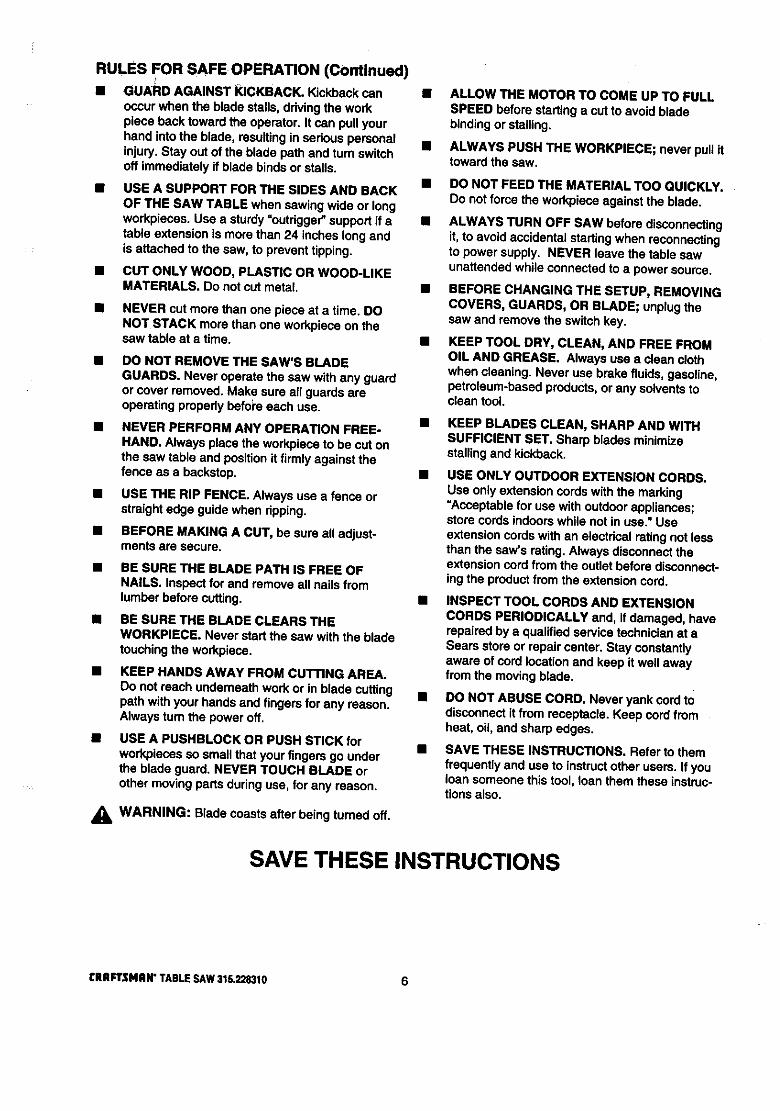
• GUARD AGAINST KICKBACK. Kickbackcanoccurwhen the blade sta$$s,ddving the workpiece back toward the operator. It can pullyourhand intothe blade, resultingin sedous personalinjury.Stay out of the blade path and turn switchoff immediatelyif blade bindsor stalls.
USE A SUPPORT FOR THE SIDES AND BACKOF THE SAW TABLE when sawing wide or longworkpieces. Use a sturdy"outrigger" support if atable extensionis morethan 24 inches long andis attached to the saw, to preventtipping.
CUT ONLY WOOD, PLASTIC OR WOOD-LIKEMATERIALS. Do not cut metal.
• NEVER cut more than one piece at a time. DONOT STACK more than one workpieceon thesaw table at a time.
DO NOT REMOVE THE SAW'S BLADEGUARDS. Never operate the saw with any guardor cover removed. Make sure all guardsareoperating propedy befol'eeach use.
NEVER PERFORM ANY OPERATION FREE-HAND. Always place the workpieceto be cut onthe saw table and position it firmly against thefence as a backstop.
USE THE RIP FENCE. Always use a fence orstraightedge guide when ripping.
BEFORE MAKING A CUT, be sure all adjust-ments are secure.
• BE SURE THE BLADE PATH IS FREE OFNAILS. Inspect for and remove all nails fromlumber before cutting.
• BE SURE THE BLADE CLEARS THEWORKPIECE. Never start the saw with the bladetouchingthe workplace.
• KEEP HANDS AWAY FROM CUTTING AREA.Do notreach underneathworkor in blade cuttingpath withyour hands and fingers for any reason.Alwaysturn the power off.
• USE A PUSHBLOCK OR PUSH STICK forworkpiecesso small that your fingersgo underthe blade guam:d.NEVER TOUCH BLADE orother movingpartsduringuse, for any reason.
_k WARNING: Blade coasts after beingtumed off.
ALLOW THE MOTOR TO COME UP TO FULLSPEED before startinge cut to avoidbladebinding or stalling.
ALWAYS PUSH THE WORKP|ECE; never pull ittoward the saw.
DO NOT FEED THE MATERIAL TOO QUICKLY.Do notfome the workpieceagainst the blade.
ALWAYS TURN OFF SAW before disconnectingit, to avoid accidental startingwhen reconnectingto power supply. NEVER leave the table sawunattended while connectedto a power source.
BEFORE CHANGING THE SETUP, REMOVINGCOVERS, GUARDS, OR BLADE; unplugthesaw and remove the switchkey.
KEEP TOOL DRY, CLEAN, AND FREE FROMOIL AND GREASE. Alwaysuse a clean clothwhen cleaning. Never use brake fluids, gasoline,petroleum-based products,or any solvents toclean tool.
KEEP BLADES CLEAN, SHARP AND WITHSUFFICIENT SET. Sharp blades minimizestalling and kickback.
USE ONLY OUTDOOR EXTENSION CORDS.Use only extensioncords withthe marking=Acceptable for use with outdoorappliances;store cords indoorswhile not in use." Useextensioncords with an electricalratingnot lessthan the saw's rating.Always disconnecttheextensioncord from the outlet before disconnect-ingthe productfrom the extensioncord.
• INSPECT TOOL CORDS AND EXTENSIONCORDS PERIODICALLY and, if damaged, haverepaired by a qualifiedsewice technicianat aSears store or repaircenter. Stay constantlyaware of cord locationand keep it well awayfromthe movingblade.
• DO NOT ABUSE CORD, Never yank cord todisconnectit from receptacle. Keep cord fromheat, oil,and sharp edges.
SAVE THESE INSTRUCTIONS. Referto themfrequently and use to instructother users. If youloan someone this tool, loan them these instruc-tions also.
SAVE THESE INSTRUCTIONS
[RAFTSMRW TABLESAW316,228310 6

EXTENSION CORDS
Use only 3-wire extensioncords that have 3-pronggroundingplugsand 3-pole receptaclesthat acceptthe tool's plug. When usinga power tool at a consid-erable distance fromthe power source, use anextensioncord heavy enough to carrythe current thatthe tool will draw. An undersized extensioncord willcause a drop in line voltage, resultingin a loss ofpower and causingthe motorto overheat. Use thechart providedbelow to determinethe minimumwiresize requiredin an extensioncord. Only roundjack-eted cords listed by Underwriter'sLaboratories(UL)shouldbe used.
Length of Extension Cord Wire Size (A.W.G.)
Up to 25 feet 1426-100 feet 12
When workingwith the tool outdoors,use an exten-sion cord that is designed for outsideuse. This isindicated by the lettersWA on the cord's jacket.Before using an extensioncord, inspect it for loose orexposed wires and cut or worn insulation.
_k CAUTION: Keep the cord away from the cuttingarea and positionthe cord so that it will not becaught on lumber, tools,or other objects dudngcuttingoperations.
ELECTRICAL CONNECTION
Your Sears Craftsman Table Saw is powered by aprecisionbuiltelectric motor. It should be connectedto a power supply that Is 120 volts, 60 Hz, AC only(normal household current). Do not operate thistoolondirect current (DC). A substantialvoltage drop willcause a lossof power and the motor will overheat. Ifthe saw does not operate when plugged intoanoutlet,double check the power supply.
SPEED AND WIRING
The no-load speed of your table saw is approximately3,600 rpm. This speed is not constantand decreasesundera load or with lowervoltage. For voltage, thewiring in a shop is as importantas the motor's horse-power rating. A line intended only for lightscannotproperlycarry a power tool motor. Wire that is heavyenough for a short distance will be too lightfor agreater distance. A line that can supportone powertool may not be able to supporttwo or three tools.
GROUNDING INSTRUCTIONS
In the event of a malfunctionor breakdown, groundingprovidesa path of least resistancefor electriccurrentto reduce the riskof electric shock. This tool isequippedwith an electric cord having an equipment-groundingconductorand a groundingplug. The plugmust be pluggedinto a matchingoutletthat is propedyinstalledand grounded in accordancewith all localcodes and ordinances.
Do not modifythe plug provided. If it will not fit theoutlet,have the proper outlet installedby a qualifiedelectrician. Improperconnectionof the equipment-groundingconductorcan result in a riskof electricshook.The conductorwith insulationhaving an outersurfacethat is green withor withoutyellowstripes isthe equipment-groundingconductor. If repairorreplacementof the electdc cord or plug is necessary,do not connect the equipment-groundingconductortoa liveterminal.
Check witha qualifiedelectricianor service personnelif the groundinginstructionsare notcompletelyunderstood,or if indoubt as to whether the tool isproperlygrounded.
Repair or replace a damaged or worn cord immedi-ately.This tool is intendedfor use on a circuit that has anoutlet likethe one shown in Figure 1. It also has agroundingpin like the one shown.
GROUNDINGPIN
COVEROFGROUNDED0UTLETBOX
Fig. 1
7 rRRFTSNRN"TABLESAW31S.228310

Anti-Kickback PawlsToothed safety devicesbehind the blade designed tostop a workpiece from beingkicked back at theoperator duringa rippingoperation.ArborThe shaft on which a blade or cuttingtool is mounted.
Bevel CutA cuttingoperationmade withthe blade at any angleother than 90" to the saw table.
Compound CutA cut with both a miterangle and a bevel angle.
CrosscutA cuttingoperation made acrossthe grain or the widthof the workpiece.
DsdoA non-throughcut that gives a square notch ortrough;requires a special blade.
FeatherboardA device to help guide workpiecesduring ripcuts.
Freehand (for table saw)Dangerous practice of making s cut withoutusingdpor miterfences. See Safety Rules.
GumA sticky, sap-based residuefromwood products.
HeelAlignmentof the blade.
KerfThe material removed by the blade in a through cut orthe slotproducedby the blade in a non-throughcut.
KickbackA hazard that can occur when blade bindsor stalls,throwingworkpiece back toward operator.
Leading EndThe end of the workpiecepushed into the cuttingtoolfirst.
Miter CutA cuttingoperationmade with the miter gage at anyangle other than 0".
MoldingA non-throughcut that givesa varied shape to theworkpiece and requires e special blade.Push StickA device usedto feed the workpiecethroughthe sawblade duringnarrowcuttingoperations. It helps keepthe operator'shands well away from the blade,
RabbetA notch inthe edge of a workpiece.
ResawA cuttingoperationto reduce the thicknessof theworkpieceinorder to make thinner pieces.
ResinA sticky,sap-based substance.
RIp CutA cut made withthe the grainof the workpiece.
Sswblade PathThe area directlyin line withthe blade -- over, under,behind, orin front of it. Also, the workpieceareawhich willbe or has been cut by the blade.
SetThe distancethat the tip of the saw blade tooth is bent(or set) outwardfrom the face of the blade.
Throw-BackSaw throwingback a workpiece;similarto kickback,
Through SawingAny cuttingoperationwhere the blade extendscompletelythroughthe workpiece.
Trailing EndThe workpieceend last cut by the blade in a dp cut.
Workp|eceThe item on whichthe cutting operationis beingdone.The surfacesof a workpieceare commonlyreferredtoas faces, ends, and edges.WorktableThe surfaceon which the wodq_ece rests whileperforminga cuttingoperation.
Blade Arbor 5/8 in.
Blade Diameter 10 in.
Blade Tilt 0" - 45"
Table Size withouttable extensions 20 in. x 27 in.
Table Size with table extensions 44 in. x 27 in.
Rating 120 V, 60 Hz - AC only
Input 13 Amperes
No Load Speed 3,600 RPM
Cutting Capacity withMiter at 0"/Bevel0": 3-3/8 in.
Cutting Capacity withMiter at O'/Bevel 45": 2-1/4 in.
rRRFTSNlUI" TABLESAW$1G,228310 8
Your new table saw has been designed to give youmany years of high qualityperformance.To insurethisgoal, proper care and treatment is important.Careful treatment beginswith removing all pads fromthe cartonand checkingthem against the listof looseparts.The long box containsthe rails. The large boxholdsall other parts, which are detailed inthe LooseParts List.
• Separate the saw and all parts from the packingmaterials and check each against the packing list,especiallythe small partsthat can be hidden inthepackingmaterial
Note: Do notdiscard the packingmaterials untilyouhave carefully inspectedthe saw, identifiedallparts, and satisfactorily operated your new saw.
_IL WARNING: Never use gasoline, naptha, orother highlyvolatile solvents.Do not ever letbrake fluids, gasoline,petroleum-basedproducts,or penetratingoilscontact plasticparts.Such chemicals can weaken or destroy plastic.
II Remove the wax paper covering on the table. Useany ordinary household type grease and spotremover. Immediatelyapply a coat of automotivetype paste wax to the table and table exensions.
,_ WARNING: To prevent accidental startingthatcouldcause possibleseriouspersonal injury,assemble all parts to your saw before connectingit to power supply.Saw should never beconnected to power supplywhen you areassembling parts, making adjustments, installingor removingblades, or when notin use.
,_ WARNING: If any partsare missing,do notoperate thistool untilthe missingparts arereplaced. Failure to do so could result inpossibleseriouspersonal injury.
The following recommended accessoriesare currentlyavailable
• Fence Guide System
• Guide Master
• Box Joint & Miter Guide
• Universal Jig
• Taper Jig
• 10 in. Sanding Disc
• 8 in. Sanding Disc• Elite Dado
• ExcaliburDado
• 7 in. Adj. Dado 36 tip
• 7 in. Adj. Dado 24 tip
at Sears Retail Stores.
• 7 in. Stack Steel Dado
• 7 in. x 9/16 in. Stack Dado
• 7 in. MoldingHead Set
• 2 Bit MoldingHead Set• Saw Baskets
• JointerClamps
• Specialty Throat Plate
• Miter Gage Hold Down Clamp
• Align-A-RipXRC Rip Fence
• Dust CollectionSystem
,_ WARNING: The use of attachmentsor accessories not listed might be hazardous.
9 [RAFTSMAN" TABLESAW315.228310
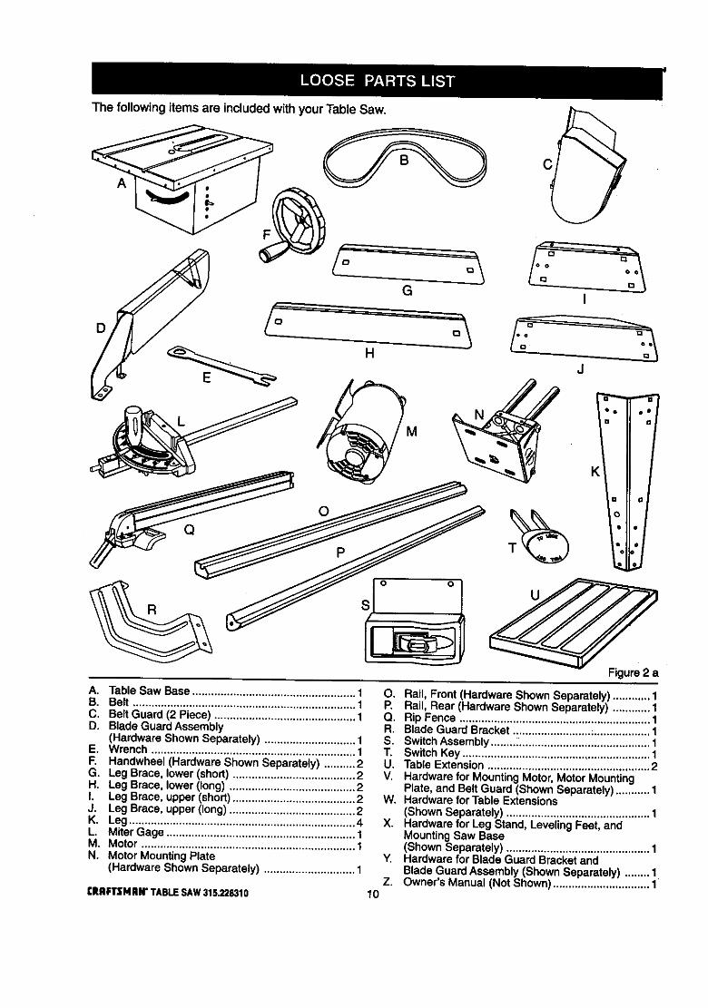
The following items are included with your Table Saw.
A
D
G
o
Q
I
J
Figure 2 a
A. Table Saw Base .................................................... 1B. Belt ....................................................................... 1C. Belt Guard (2 Piece) ............................................. 1D. Blade Guard Assembly
(Hardware Shown Separately) ............................. 1E. Wrench ................................................................. 1F. Handwheel (Hardware Shown Separately) .......... 2G. Leg Brace, lower (short) ....................................... 2H. Leg Brace, lower(long) ........................................ 2I. Leg Brace, upper(short)....................................... 2J. Leg Brace, upper (long) ........................................ 2K. Leg ........................................................................ 4L. Miter Gage ............................................................ 1M. Motor .................................................................... 1N. Motor MountingPlate
(Hardware Shown Separately) ............................. 1
tRRFTZMRI¢ TABLE SAW 315.228310
O. Rail, Front(Hardware Shown Separately)............ 1P. Rail, Rear (Hardware Shown Separately) ............ 1Q. Rip Fence ............................................................. 1R. Blade Guard Bracket ......................... ;.................. 1S. SwitchAssembly ......,, ......................................... 1T. SwitchKey ............................................................ 1U. Table Extension .................................................... 2V. Hardware for MountingMotor, MotorMounting
Plate, and BeltGuard (Shown Separately) ........... 1W. Hardware for Table Extensions
(Shown Separately) .............................................. 1X. Hardware for Leg Stand, LevelingFeet, and
MountingSaw Base(Shown Separately) .............................................. 1
Y. Hardware for Blade Guard BracketandBlade Guard Assembly (ShownSeparately) ........ 1
Z. Owner's Manual (Not Shown)............................... 110
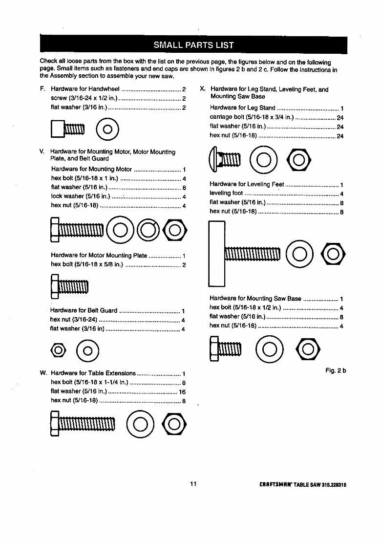
Checkallloosepartsfromtheboxwiththelistonthepreviouspage,thefiguresbelowandonthefollowingpage,Smallitemssuchasfastenersandendcapsareshowninfigures2band2c.FollowtheinstructionsintheAssemblysectiontoassembleyournewsaw.
F. Hardware for Handwheel ................................... 2
screw (3/16-24 x 1/2 in.)..................................... 2
flat washer (3/15 in.) ........................................... 2
V. Hardware for MountingMotor, MotorMountingPlate, and Belt Guard
Hardware for Mounting Motor ............................ 1
hex bolt (5/16-18 x 1 in.) .................................... 4
flat washer (5/16 in.) ........................................... 8lock washer (5/16 in.) .......,.................................. 4
hex nut (5/16-18) ................................................ 4
Hardware for Motor MountingPlate ................... 1
hex bolt (5/16-18 x 5/8 in.) ................................. 2
Xo Hardware for Leg Stand, LevelingFeet, andMountingSaw Base
Hardware for Leg Stand ..................................... 1
carriage bolt (5/16-18 x 3/4 in.) ........................ 24
flat washer (5/16 in.)......................................... 24
hex nut(5/16-18) .............................................. 24
Hardware for Leveling Feet ................................ 1
leveling foot ........................................................ 4
flat washer (5/16 in.) ........................................... 8
hex nut (5/16-18) ................................................ 8
Hardware for Belt Guard .................................... 1
hex nut (3/16-24) ................................................ 4
flat washer (3/16 in) ............................................ 4
W. Hardware for Table Extensions.......................... 1
hex bolt (5/16-18 x 1-1/4 in.) .............................. 8
flat washer (5/16 in.) ......................................... 16
hex nut (5/16-18) ................................................ 8
m
Hardware for MountingSaw Base ..................... 1
hex belt (5116-18 x 1/2 in.) ................................. 4
flat washer (5/16 in°)........................................... 8
hex nut (5116-18) ................................................ 4
Fig. 2 b
11 [IIRFrSMRIr TABLESAW31S.228310
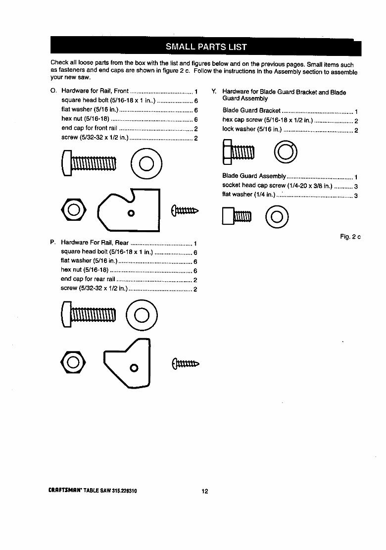
Check all loose parts from the box with the listand figuresbelow and on the previouspages, Small items suchas fasteners and end caps are shown in figure2 c. Follow the instructionsin the Assembly sectionto assembleyour new saw.
O. Hardware for Rail, Front ..................................... 1
square head bolt (5/16-18 x 1 in..) ..................... 6
flat washer (5/16 in.) ........................................... 6
hex nut (5/16-18) ................................................ 6
end cap for front rail ........................................... 2
screw (5/32-32 x 1/2 in.) ..................................... 2
©
F, Hardware For Rail, Rear .................................... 1
square head bolt (5/16-18 x 1 in.) ...................... 6
flat washer (5/16 in.) ........................................... 6
hex nut (5/16-18) ................................................ 6
end cap for rear rail ............................................ 2
screw (5/32-32 x 1/2 in.) ..................................... 2
Y. Hardware for Blade Guard Bracketand BladeGuard Assembly
Blade Guard Bracket .......................................... 1
hex cap screw (5/16-18 x 1/2 in.) ....................... 2
lock washer (5/16 in.) ......................................... 2
Blade Guard Assembly....................................... 1
socket head cap screw (1/4-20 x 3/8 in.) ........... 3
flat washer (1/4 in.) ..._......................................... 3
Fig. 2 c
CRAFTSMAN"TABLESAW315.228310 12
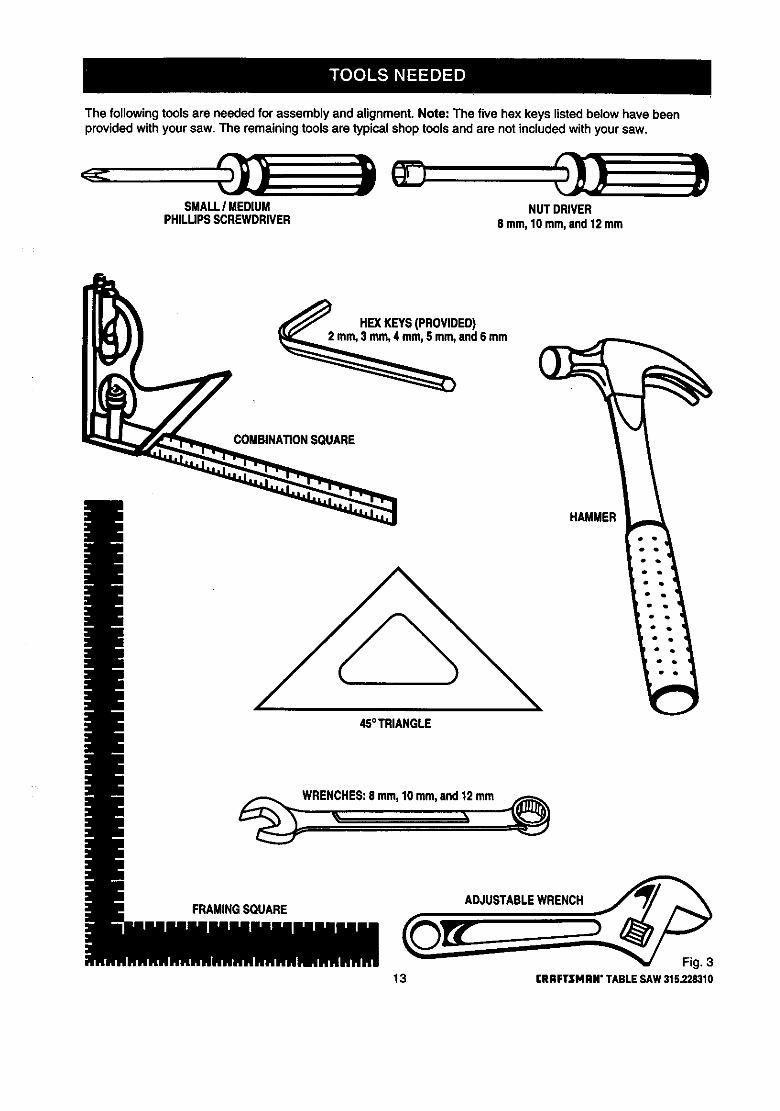
The followingtoolsare needed for assemblyand alignment. Note: The five hex keys listedbelow have beenprovidedwith your saw. The remainingtools are typicalshop toolsand are notincludedwithyour saw.
SMALLI MEDIUMPHILUPSSCREWDRIVER
NUTDRIVER8 mm,10mm,and12mrn
HEXKEYS(PROVIDED)
and6 mm
COMBINA_ONSOUARE
HAMMER
45°TRIANGLE
WRENCHES:8 mm,10mm,and12mm
FRAMINGSQUARE ADJUSTABLEWRENCH
13 rRRFTSMRN" TABLESAW315.228310

/
The followinglabels are found on your saw inthe locationsshown. Read allwarnings and thisowner's manualbefore using saw,
B
D
e
o
o
A
10 inch Table Saw36QOIh_M120VOLTS60HzACONLY13A
WARNING:WHEN SERVICING, USE ONLY IDENTICALCRAFTSMANREPLACEMENTPARTS.
MODEL 315.228310 S_R.NO. _iMAD_ IN TAJWANSEARS, ROEBUCK AND CO. i I sr_l_4_ TOOL
• Customer Help Line 1-800-932-3188 ,
F
H
C
G
B
AWARNINI
• RaisedGuardCanDroponSpinningBladeandBreak.
•ToReduceTheRiskofInjury,GuardMust81InPlaceDuringUse.
,AlignandTightenRivingKnifeFastenersBeforeUse.
Fig, 4 aCRAFTSMAN"TABLESAW315.228310 14
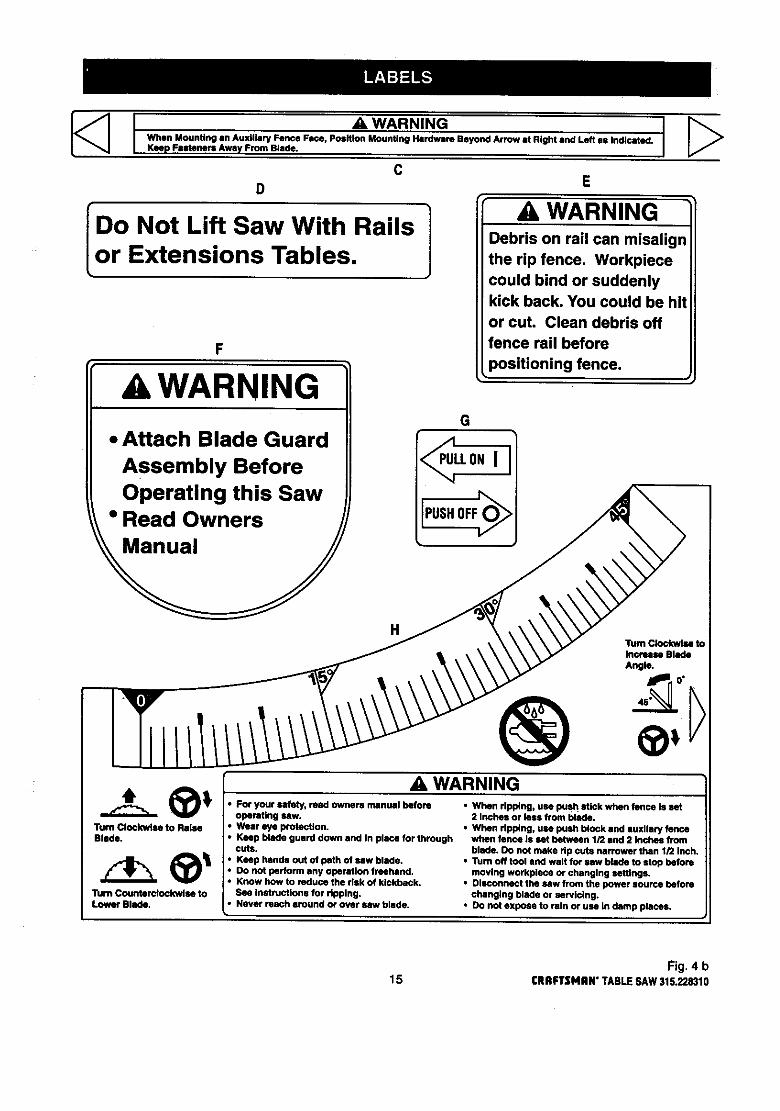
I _ WARNINGWhen Mounting an Auxiliary Fence Face, Position Mounting Hardware Beyond Arrow at Bight and Left as Indicated.Keep Fasteners Away From Blade.
CD E
I ] ,A, WARNINGDo Not Lift Saw With Rails Debris on rail can misalign
Lor Extensions Tables. the rip fence. Workpiececould bind or suddenly
F
A WARNING
• Attach Blade Guard
Assembly BeforeOperating this Saw
• Read Owners
kick back. You could be hit
or cut. Clean debris off
fence rail before
positioning fence.
G
,_LLONI
PUSHOFF
H
®A WARNING
Turn Clockwise toIncrease Blade
Angle.
Turn Clockwise to RaiseBlade.
"rumCounterclockwise toLower Blade.
• For your safety, read owners manual before
operating saw.• Wear eye p_otection.
• Keep blade guard down and In place for throughcuts.
• Keep hands out of path of saw blade.• Do not perform any operation freehand.• Know how to reduce the risk of kickback.
See instructions for ripping.• Never reach around o¢ over/Niw blade.
• When ripping, use push stick when fence is set2 Inches or lees from blade.
• When ripping, use push block and auxllary fencewhen fence Is set between 1/2 and 2 inches from
blade. Oo nut make rip cuts narrower than 1/2 Inch.•Tum off tool and walt for saw blade to stop before
moving workplece or changing settings.• Disconnect the saw from the power source before
changing blade or se_icing.
• Do not expose to rbln or use in damp places.
Fig. 4 b15 I:RRFTSMIIN"TABLESAW315.228310

KNOW YOUR TABLE SAW
ANTI-KICKBACKPAWLS
BLADE
MITERGAGEGROOVE
TABLEEXTENSION
BLADE
REARRAIL RIPFENCERIVINGKNIFEORSPREADER ALIGN-A-CUT TABLE
INSERT EXTENSION
SCALE
GAGE
FRONTRAIL
BELTCOVER
BEVEL SWITCHHANDWHEEL WITH KEY
RIPFENCESCALE HANDLE
HANDWHEEL
LEGSTAND
'LEVELINGFOOT
MOTORBEVEL
LOCKHANDLE
Fig. 5CRAFTSMAN"TABLESAW315.228310 16

/ERVIEW
, ,,e upper portionof the blade projectsup throughthetable, surroundedby an insertcalled the throat plate.The height of the blade is set witha handwheel andlocked with a handle, both on the front of the cabinet.To accommodate wide panels, the tabletop hasextensionson each side. Detailed instructionsareprovidedinthe Operationsection of this manual forthe basiccuts: crosscuts, mitercuts, bevel cuts,andcompoundcuts.
For cuts with the blade straightup and cuttingacrossthe grain(cross cuts or mitercuts), use the mitergageto set the angle and pushthe wood into the blade. Tocut with the blade straight up, along the grain of thewood (rip cuts), use the rip fence to guide the wood.Push smaller pieces with a pushblockor pushstick.
To tilt the blade for a bevel cut, use the bevelhandwheel on the side of the cabinet. A bevel scaleon the front of the cabinet showsthe blade angle.Insidethe cabinet, adjustable positivestopscontrolthe degree of tilt.
Use the miter gage with a bevel crosscut (compoundcut) and the rip fence with a bevel ripcut. Other cutsrequire special attachments, which have detailedinstructions to reduce risk of injury and ensure thebest performance from your new saw.
Before attempting to use your saw, familiarize yourselfwithall operating features and safety requirements ofyour Sears Craftsman table saw. The saw's featuresare described below.
ALIGN-A-CUT INSERT - A pt_,stic insert onwhichmarks may be made to indicate the locationof thesawcut on the workpiece.ANTI-KICKBACK PAWLS - KickbackIs a hazard inwhich the workpiece is thrownback toward theoperator. The toothed pawls are designed to snag theworkpieceto prevent or reduce injury should kickbackOccur.
BEVEL HANDWHEEL - This handwheel, on the rightside of the cabinet, tiltsthe blade for a bevel cut.
BEVEL SCALE - The easy-to-road scale on the frontof the work.standshowsthe exact blade angle.
BLADE -This saw is providedwith a Craftsman 64tooth, 10 in. steel blade. The blade is adjustedwithbevel and heighthandwheels on the cabinet. Bevelangles are locked with a handle below the front rail.
WARNING: Be sure to use only blades rated forat least 5,000 rpmand recommended for use onthis saw. Check with your nearest Sears retailstore.
BLADE GUARD - Always keep the guard down overthe blade for through-sawingcuts.BEVEL LOCK HANDLE - This handle, placed justunder the worktable surfaceon the front of the cabi-net, locksthe angle setting of the blade. Be surethehandle is hangingstraightdown before tilting theblade. If it is notstraightdown, it may jam and bendthe lockingbolt.HEIGHT HANDWHEEL - Use this handwheel to lowerand raise the blade for adjustmentsor replacement. Itis locatedon the front of the cabinet.
MITER GAGE - This gage alignsthe wood for acrosscutat an angle other than 90". The easy-to-road
indicator showsthe exact angle for a mitercut, withpositivestopsat 90" and 45".
MITER GAGE GROOVES - The miter gage ddes inthese grooves on either side of the blade.
MITER GAGE KNOB - Located on the miter gage,this knob locksin the cuttingangle after selection.
MOTOR (13 AMP) - The powerfulinductionmotor is3HP, with capacitorstart and V-belt drive,and ishousedin a sturdy steel base.
RAILS - Front and rear rails providesupportfor largeworkpiecesend the ripfence.
RiP FENCE - A sturdy metal fence guidestheworkpieceand is secured withthe rip fence handle.Grooves run alongthe top and sidesof the ripfencefor usa withoptionalclamps and accessories.RIP FENCE HANDLE - The handleon the front of therip fence releasesthe rip fence or locksit in place.
RIVING KNIFE OR SPREADER - Located directly.behindthe blade, it keeps cut edges frombindingandsupportsthe blade guard.SCALE - Found on the front rail, the easy-to-roadscale providesprecise measurementsin dp cuts.SWITCH WITH KEY - Your table saw has an easyaccess power switchlocated below the front rail.Theyellow switchkey must be removed fromthe hard-ware bag and inserted into the switchbefore saw canbe operated. To lockthe switchinthe OFF position,remove the switch key fromthe switch. Place the keyin a location that is inaccessibleto childrenand othersnotqualifiedto use the tool.
TABLE EXTENSIONS - Removable stampedsteelextensions, 12 in. by 27 in., supportlargerworkpieces,
17 CRAFTSHAN"TABLESAW315.228310
Assembly is best done inthe area where the saw will be used. When you remove the table saw base, looseparts, and hardware fromthe packingmatedals, check all items with the loose parts listand drawing. If you areunsure about the descriptionof any part, refer to the drawing. If any parts are missing, delay assemblinguntilyou have obtained the missingpart(s).
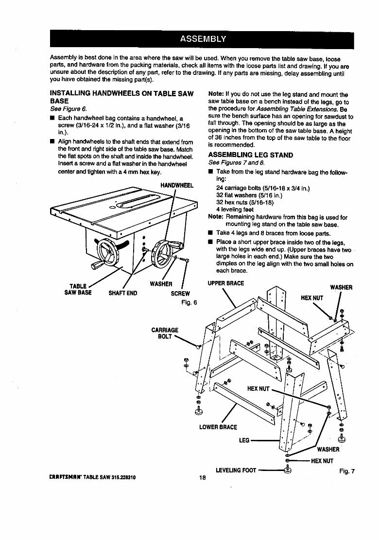
INSTALLING HANDWHEELS ON TABLE SAWBASE
See Figure 6.
• Each handwheel bag containsa handwheel, ascrew (3/16-24 x 1/2 in.), and a flat washer (3/16in.).
• Alignhandwheelsto the shaftendsthat extendfromthe frontand rightsideof the table sawbase. Matchthe fiat spotson the shaftand insidethe handwheeLInserta screwand a fiatwasherin the handwheel
centerandtightenwitha 4 mmhex key.
HANDWHEEL
Note: If you do not usa the leg stand and mount thesaw table base on a bench instead of the legs, gotothe procedurefor Assembling Table Extensions. Besure the 'bench surfacehas an openingfor sawdusttofall through.The opening shouldbe as large as theopening in the bottomof the saw table base, A heightof 36 inchesfromthe top of the saw table to the flooris recommended.
ASSEMBLING LEG STANDSee Figures 7 and 8.
• Take from the legstand hardware bag the follow-ing:
24 carriagebolts (5/16,18 x 3/4 in.)32 flat washers (5/16 in.)32 hex nuts(5/16-18)4 levelingfeet
Note: Remaininghardwarefrom thisbag is usedformountingleg standon the table saw base.
• Take 4 legs and 8 bracesfrom loose parts.
• Place a shortupper brace insidetwo of the legs,withthe legswide end up. (Upper braceshave twolarge holes in each end.) Make sure the twodimplesonthe leg alignwith the two small holes oneach brace.
TABLE WASHERSAWBASE SHAFTEND SCREW
Fig. 6
UPPERBRACE
HEXNUT%
WASHER
CARRIAGE
LOWERBRACE
LEG
[RRFTSMIIN" TABLESAW315,228310
HEXNUT
LEVELINGFOOT_ Fig. 718
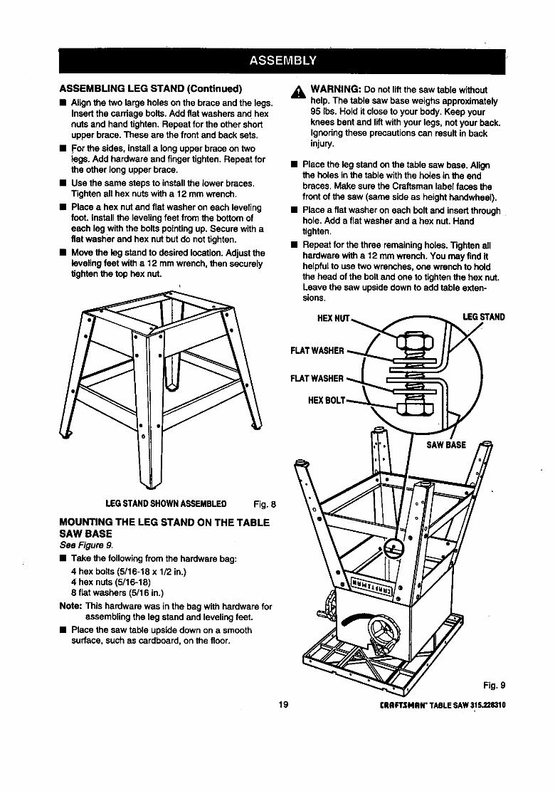
ASSEMBLINGLEGSTAND(Continued)• Align the two large holes on the brace and the legs.
Insert the cardage bolts.Add flat washersand hexnuts and hand tighten. Repeat forthe other shortupper brace. These are the front and back sets.
• For the sides, installa long upperbrace on twolegs. Add hardware and fingertighten. Repeat forthe other long upperbrace.
• Use the same steps to installthe lower braces.Tighten all hex nutswith a 12 mm wrench.
• Place a hex nut and flat washer on each levelingfoot. install the levelingfeet fromthe bottomofeach legwith the boltspointingup. Secure withafiat washer and hex nutbut do nottighten.
• Move the leg standto desiredlocation.Adjusttheleveling feet witha 12 mmwrench, then securelytightenthe top hex nut.
_k WARNING: Do notlift the saw table withouthelp. The table saw base weighs approximately95 Ibs. Hold it closeto your body. Keep yourknees bent and liftwith your legs, notyour back.Ignoringthese precautionscan result in backinjury.
• Place the legstand on the table saw base. Alignthe holes inthe tablewith the holes in the endbraces. Make surethe Craftsman label faces thefront of the saw (same sideas heighthandwheel).
• Place a flat washeron each bolt and insertthroughhole. Add a flat washerand a hex nut. Handtighten.
• Repeat for the three remainingholes.Tighten allhardwarewith a 12 mmwrench. You may find ithelpfulto use two wrenches,one wrench to holdthe head of the boltand one to tightenthe hex nut.Leave the saw upsidedownto add table exten-sions.
HEXI, LEGSTAND
LEGSTANDSHOWNASSEMBLED Fig. 8
MOUNTING THE LEG STAND ON THE TABLESAW BASESee Figure 9.
• Take the followingfrom the hardwarebag:
4 hex bolts(5/16-18 x 1/2 in.)4 hex nuts (5/18-18)8 flat washers (5/16 in.)
Note: This hardwarewas inthe bagwith hardwareforassemblingthe leg stand and levelingfeet.
• Place the saw table upsidedown on a smoothsurface, such as cardboard, on the floor.
Fig. 9
19 CRAFTSMRN"TABLESAW315.228310

ASSEMBLING TABLE EXTENSIONS
See Figure 10.• Locate the table extensionsand the smal_hardware
bag withthe following:
8 hex bolts(5/16-18 x 1-1/4 in.)8 hex nuts (5/16-18)
16 fiat washers (5/16 in.)
,_ WARNING: The table extensions notonlyprovidea supportfor large or wide pieces ofmaterial, but help protect you. Serious injurycan result from workpiece bindingor kickbackdue to twisted rails or a misaligned rip fence.
• With the saw upsidedown, align table extensionstothe sawtable. Put a flat washer on each bolt,andattach the extensionsto the table by insertingboltsthroughholes from the directionof the table.
• Slip the remaining flat w_shers and hex nuts on thebolts. Lightly tighten with a 12 mm wrench.
• Get help to standsaw assemblyupdght usingthecentersaw table. Do notgrasp saw by extensions.
_i, WARNING: Do not lift the saw table withouthelp. Hold it closeto your body. Keep yourknees bent and liftwithyour legs, not your back.Ignoringthese precautionscan result in backinjury.
ALIGNING TABLE EXTENSIONSSee Figure 11.
A good alignment allowsthe railsto slide on easily.
• Stand at the frontof the saw and line up the frontedgesof the table and extensions.
• if adjustmentsare needed, puta blockof woodwherethe extensionmeetsthe table, and tap theblockof wood with a hammer. Check and repeatuntilthe frontedges are even.
• Lifteach extensionslightlyuntilit is higherthantable (if necessary, placea blockbelow and tapupward). Center the blockof wood overthe edgesand tap it. Recheckthe front alignment. If even,tightenthe screwswith a 12 mm wrer,_h.
BLOCK TABLEOFWOOD EXTENSION
TABLEEXTENSION
SAWTABLE
BLOCK TAP TABLEOFWOOD HERE EXTENSION
HEXHEAD BOLT
FLA;WASHER
HE](NUTFig. 10
Fig. 11
eRRFTSMRI_ TABLESAW3152.28310 20

INSTALLING THE REAR RAIL
See Figures 12 - 14.
,_ WARNING: Frontand rear rails must beinstalledand carefullyaligned to reduce the riskof kickback. Kickbackcan result in seriousinjury.
• From the carton,remove the rear rail and thefollowinghardware:
6 square head bolts(5/16-18 x 1 in.)6 flat washers (5/16 in.)6 hex nuts(5/16-18)Right and left end caps for rear rail2 screws (5/32-32 x 1/2 in.)
Note: Remaininghardware from this hardware bag isused for installingthe front rail and end caps.
• At the back of the table, put the square head boltsinthe holes in the edge of the table and extensionsso the bolt headsextend outward 1/2 in.
• Underthe table, looselyattach washers and hexnutsonto bolts.Slide the sloton the rear rail overthe bolts.Adjusteach boltto fit the rail closelytothe table.
• Positionrail so that righthand edge extends 2-1/2inches beyondtable extension.
• Pushthe rail against table and tighteneach nutwitha 12 mm wrench.
• If the railjams and does notslide easily over thebolts,re-alignthe table extensions.
• Put the end caps on the rail ends. Insert the screwsand tightenwitha phillipshead screwdriver.
SLOTREARRAIL
TABLEEXTENSION
SQUARE HEXNUTHEADBOLTS FLAT
WASHER Fig. 12
SQUAREHEADBOLTS
TABLE
FLATWASHER
SCREW
NUT
REARRAIL
Fig. 13
ENDCAP
REAR OF SAW Fig. 14
21 CRRFTSNAN" TABLE SAW 315.228310

INSTALLING THE FRONT RAIL
See Figures 15and 16.
• Get the front rail the switchassembly, and thefollowinghardware:
6 square head botts(5/16-18 x 1 in.)6 fiat washers (5/16 in.)6 hex nuts (5/16-18)2 screws (1/4-20 x 3/8 in.) (located on switch plate)2 square nuts (1/4-20) (located on switchplate)Rightand left end caps for front rail2 screws (5/32-32 x 1/2 in.)
• Set aside end caps and screws untilyou havealignedthe dp fence and front rail.
• Insertthe six square head boltsinto the table andextensions,so the bolt heads extend outward 112in.
• Looselyattach a washer and a hex nut to each bolt.
• The back of the rail has two slots.Slide the upperslotover the bolts. (Bottom slot is for switch.)
• Alignthe rail left to fight - Match the 7-1/8 in. markon the dghtscale to the dghtedge of the table sawbase (main table). See Figure 16.
• Snug the rail against table. Finger-tighteneach nutonthe table and extensions.
• Locatethe switchassembly. The two screws areinstalledthroughthe back of the switchplate withthe square nuts extendingout toward the front.
Note: The square nutsare loose on the switchplate.
• Slide the square nuts intothe lower slotof the rail.
• Slide the switchassembly to a convenient position,leavingample clearance for the haedwheeLTightensecurelywitha screwdriver. Do nottightenthe railbolts.
A_ WARNING: Place the switchout of theimmediate work area to avoid accidentallyturningit off dudng operation.
TABLETABLE
EXTENSION
SOUAREHEADBOLTS
TABLEEXTENSION
SCALE
FRONTRAIL
HEX NUT
FLATWASHER
Fig.!5
ENDCAP
SCREW
TABLEEXTENSION
_IRIn.MARKR_HTBCALE
SWITCH.WITHKEY
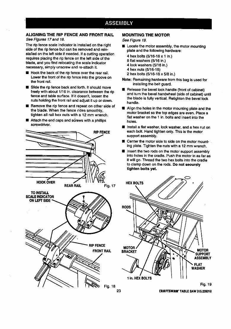
ALIGNINGTHERIPFENCEANDFRONTRAILSee Figures 17and 18.
The ripfence scale indicatoris installedon the rightside of the rip fence but can be removed and rein-stalled on the left side if needed. If a cuttingoperationrequiresplacing the rip fence on the left side of theblade, and you find relocatingthe scale indicatornecessary, simply unscrewand re-attach it.
• Hook the back of the rip fence over the rear rail.Lower the frontof the rip fence into the grooveonthe front rail.
• Slide the rip fence back and forth. It should movefreely withabout 1/16 in. clearance between the ripfence and table surface. If it doesn't, loosenthenuts holdingthe front rail and adjust it up or down.
• Remove the rip fence and repeat on other side ofthe blade. When the fence rides smoothly,tighten all rail hex nuts with a 12 mm wrench.
• Attachthe end caps and s_rews witha phillipsscrewdriver.
NCE
ooREARRAIL Fig. 17
TOINSTALLSCALEINDICATOR
ONLEFT
MOUNTING THE MOTOR
See Figure 19.
• Locate the motorassembly, the motor mountingplate and the followinghardware:
4 hex bolts (5/16-18 x 1 in.)8 flat washers (5/16 in,)4 lockwashers (5/16 in.)4 hex nuts(5/16-18)2 hex bolts(5/16-18 x 5/8 in.)
Note: Remaininghardwarefromthis bag is used forinstallingthe belt guard.
• Release the bevel lock handle (frontof cabinet)and turn the bevel handwheel (sideof cabinet) untilthe blade is fullyvertical. Retightenthe bevel lockhandle.
• Align the holes inthe motormountingplate and themotor bracketso the top edges are even. Place aflat washer on the 1 in. boltsand insert into theholes.
• Installa flat washer, lockwasher, and a hex nut oneach belt. Hand tightenonly.This is the motorsupportassembly.
• Center the motorside to side on the motor mount-ing plate. Tighten the nutswitha 12 mm wrench.
• Insert the two rodson the motor supportassemblyinto holes in the cradle. Pushthe motor in as far asit will go. Thread the two hex bolts intothe cradleto clamp down on the rods. Do not securelytighten bolts yet.
HEX BOLTS
RODS
RIPFENCE
FRONTRAILMOTOR
BRACKET MOTOR
ASSEMBLY
1 In.HEXBOLTS
WASHER
Fig. 18 Fig. 1923 CRRFTSNRN"TABLESAW315.228310
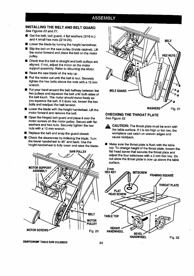
INSTALLINGTHEBELTANDBELTGUARDSee Figures20 and 21.
• Get the belt, belt guard, 4 flat washers (3/16 in.)and 4 smallhex nuts (3/16-24).
• Lower the blade by turningthe heighthandwheel.
• Slip the belton the saw pulley(insidecabinet). Liftthe motorforwardand place the belt on the motorpulley.
• Check that the belt is straightand both pulleysareaSgned. If not, adjustthe motoron the motorsupportassembly. Refer to Mountingthe Motor.
• Raise the saw blade all the way up.
• Pullthe motor out until the belt is taut. Securelytightenthe hex boltsabove the rods witha 12 mmwrench.
• Put your hand around the belthalfwaybetween thetwo pulleysand squeeze the be_tuntil bothsidesofthe belt touch.The motor shouldmove freelyasyou squeeze the belt. If i_does not, loosenthe hexboltsand readjustthe belt tension.
• Lower the blade with the heighthandwheel.Lift themotorforwardand remove the belt.
• Open the hinged belt guard and place it over themotorscrews on the motorpulley. Secure withfiatwashers and hex nuts. Securely tightenthe hexnuts witha 10 mm wrench.
• Replace the belt and snap the guardclosed.
• Checkthe clearances by indexingthe blade.Turnthe bevel hendwheel to 45" and back. Use theheighthandwheelto fully lower and raise the blade.
SAWPULLEY
MOTORSUPPORTASSEMBLY
MOTORSCREWS
rRRFTSMRN"TABLESAW315,228310
BELT
BELTI
MOTOR
Fig. 20
24
CHECKING THE THROAT PLATESee Figure 22.
Fig. 21
j_ CAUTION: The throatplate must be even withthe table surface. If it is too highor too low, theworkpiece can catch on uneven edges andcause kickback.
• Make sure the throat plate is flush with the tabletop. To change heightof the throat plate, loosentheflat head screw that securesthe throat plate andadjust the four setscrewswitha 2 mm hex key. Donot allow the throatplate to bow up above the tablesurface.
2mmHEXKEY SETSCREW
FRAMINGSQUARE
IROATPLATE
TABLETOP
HEIGHTHANDWHEEL
BEVELHANDWHEEL Fig. 22

INSTALLING THE BLADE GUARD
See Figures 23 - 25.
WARNING: If the blade is not fully lowered, tumthe heighthandwheel to lower the blade toprevent injury.
• Locatethe blade guard, the blade guardbracket,and the followinghardware:
2 hex bolts (5/16-18 x 1/2 in.)2 lockwashers (5/16 in.)3 socket head screws (1/4-20 x 3/8 in.)3 fiat washers (1/4 in.)
• Align the lower end of the blade guard bracketandthe threaded holes of the cradle and insertthe hexboltsand _ockwashers. Securely tk3htanwith a 12mm wrench.
• Remove the throat plate. See page 32.
• Put the blade guard assemblyin place on the tabletop, aligningthe screw holes inthe rivingknifetothe holes in the bracket. Align the hole inthe frontof the rivingknifebase withthe screw hole in thesaw table.
Note: The screw hole is located underthe slot in backof the throat plate.
• Inserttwo socket head screws and two flat washersinthe two holes at the beck of the dyingknifebase.Securelytightenwith a 5 mm hex key.
• Insertthe thirdsocket head screw and flat washerinto screw hole in saw table underthroat plate.Securelytightenwith a 5 mm hex key.
• Replace the throat plate.
SOCKETHEADSCREWS
FLMWASHER
SOCKETHEADSCREW
FLATRIVINGKNIFE
BLADE
Fig. 24
BLADE
BLADEGUARD
BRACKET
_NTI-KICKBACKPAWLS
LOCKWASHER
HEXFig. 25
Fig. 2325 CRRFTSNnN"TABLESAW315.228310

ALIGNINGTHERIVINGKNIFEWITHTHEBLADESee Figures26 - 28.
_l, WARNING: Make sure the switchis off, theswitchkey is removed, and your saw isunplugged. Failure to do so could result inaccidental starting, causing serious personalinjury.
The rivingknife must be aligned withend centeredoverthe blade.
_I, WARNING: It is importantto installand adjustthe riving knifecorrectly. Poor alignment couldcause kLckbackand throw the workpiece at theoperator.
• Raisethe blade guard.
• Place a framing square or straightedgebeside theblade on the left. See Figure 26.
• Loosen the front screw on the riving knife with a5 mm hex key. See Figure 27.
• Center the rivingknifeover the blade. See Figure28.
• Securelytightenthe screw witha 5 mm hex key.
RMNG KNIFE
BLADE
SAWTABLE
FRAMINGSQUARE Fig. 26
BLADE GUARD
RIVINGKNIFE
BLADE
/Fig. 27
RIVINGKNIFE
I/
FRAMINGSQUARE
BLADE
_ROATPLA_
/
TOPVIEWOFSAWWITHRIVINGKNIFESHOWNCENTEREDOVERBLADE
Fig. 28
rRIIfTSMRN" TABLESAY/315.22S310 26

CHECKING RIP FENCE AND BLADEALIGNMENT
See Figures 29 - 31.
The rip fence is self-aligningbut shouldbe checkedbefore first use.
_, WARNING: Failure to align the rip fence to theblade can cause jams and kickback,resultinginseriouspersonal injury.
• Slide the ripfence to the mitergage groove, whichis parallelto blade. Do not lockthe rip fence.
• Place a framing square against the blade,with thelongend underthe ripfence. Note the distance.
• Movethe square to the back and measure thelength from the other end of the fence.
• If the distancesare different, loosenthe four screwsaround the ripfence handlewith a 6 mm hex key.Alternatethe order (loosenthe screw opposite,notnext to the first one).
• Holdthe fence handle against the front rail andalignthe rip fence withthe blade.
• Retightenthe screws in alternatingorderand checkthe alignment.
• Repeat untilthe rip fence is aligned.
To complete assemblyof the saw, plug the motorcordinto the back of the switch. Run the cord around theside of the cabinet. Secure it to the side of the cabinetwiththe cord clip and screw provided. Use care withthe cord around sharp edges. Your saw is now set upto provide years of highquality performance.
BLADE
MITERGAGEGROOVE
RIPFENCE
FRAMINGSQUARE
€
BLADE
MITERGAGEGROOVE
RIPFENCE
FRAMINGSOUARE
Fig. 30
RIP FENCE
RIPFENCEHANDLE Fig. 31
Note: To insureproperself alignmentwhen positiOn-ing rip fence, push sidesof scale indicatorhousingagainst front railbefore lookingripfence handle.
Fig. 29
27 CRaFTSMRN"TABLESAW315.228310
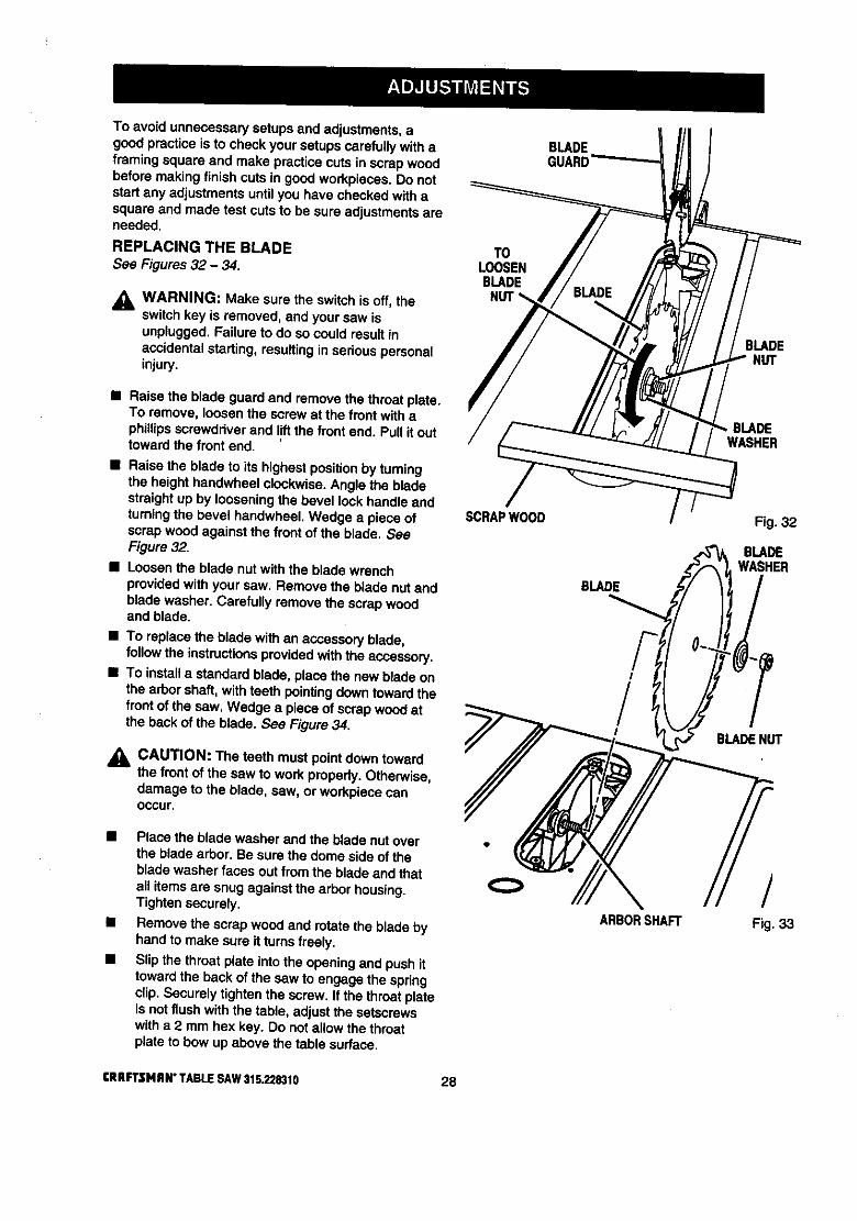
To avoid unnecessarysetupsand adjustments,agoodpractice is to check your setupscarefullywith aframing square and make practicecuts in scrapwoodbefore making finish cuts in goodworkpieces. Do notstart any adjustmentsuntilyou have checkedw_thasquare and made test cuts to be sure adjustmentsareneeded.
REPLACING THE BLADESee Figures 32 - 34.
_1, WARNING: Make sure the switchis off, theswitchkey is removed, and your saw isunplugged. Failure to do so could result inaccidentalstarting, resultinginseriouspersonalinjury.
T0LOOSENBLADE
BLADEGUARD
BLADE
• Raise the blade guard and remove the throat plate.TO remove, loosenthe screw at the front withaphillipsscrewddver and I!ftthe front end. Pull it outtoward the front end.
• Raise the blade to its highestpositionby turningthe height handwheel clockwise.Angle the bladestraightup by looseningthe bevel lockhandle andturningthe bevel handwheet.Wedge a piece ofscrapwood against the frontof the blade. SeeFigure 32.
• Loosenthe blade nut with the bible wrenchprovidedwithyour saw. Remove the blade nut andblade washer. Carefully remove the scrap woodand blade.
• To replace the blade with an accessoryblade,follow the instructionsprovidedwiththe accessory.
• To install a standard blade, place the new blade onthe arbor shaft,withteeth pointing down towardthefront of the saw, Wedge a piece of scrap woodatthe back of the blade. See Figure 34.
CAUTION: The teeth must pointdown towardthe front of the saw to work properly.Otherwise,damage to the blade, saw, or workpiececanoccur.
SCRAPWOOD
BLADE
I
/I
BLADEWASHER
BLADEHUT
• Place the blade washer and the blade nut overthe blade arbor. Be sure the dome side of theblade washer faces out from the blade and thatall items are snug againstthe arbor housing.Tightensecurely.
• Remove the scrapwood and rotate the blade byhand to make sure it turns freely.
• Slip the throat plate intothe openingand push ittoward the back of the saw to engage the springclip,Securely tightenthe screw. If the throat plateis not flush with the table, adjust the setscrewswith a 2 mrn hex key. [3o not allow the throatplateto bow up above the table surface.
ARBORSHAFT
/Fig. 33
[RRFTSMRW TABLESAW$15.2283t0 28

SCRAPWOOD BLADEGUARD
BLADE NUT
WASHER
TOTIGHTENBLADENUT Fig. 34
HEELING (PARALLELING) THE SAWBLADETO THE MITER GAGE GROOVESee Figures 35 - 37.
DO NOT loosen any screws for this adjustmentuntil you have checked with a square and madetest cuts to be sure adjustments are necessary.Once the screws are loosened, these Items mustbe reset.
_k WARNING: Make sure the switchis off, theswitchkey is removed, and your saw is un-plugged. Failure to do so couldresult in acciden-tal starting, resultingin seriouspersonal injury.
_l, WARNING: The sawblade must be parallel tothe mitergage groove so the wood does notbind, resultingin kickback.You couldbe hitorcut.
• Lift the blade guard. Raise the blade all the way byturning the height handwheel.
• Mark one of the sawblade teeth at the front of theblade. Place a framing square beside the blade andjust touching the marked tooth. Measure thedistance to the right miter gage groove.
• Turn the sawblade so the marked tooth is at theback.
• Move the square to the rear and again measure thedistanceto the rightmitergage groove. If thedistancesare the same, the blade and the mitergage groove are parallel.
/MITERGAGEGROOVE
FRAMINGSQUARE
Fig. 35
(_ FRAMINGSQUARE
fMITERGAGEGROOVE Fig. 36
• If the distancesmeasured are different,adjust themechanismunderneaththe saw.
j_ WARNING: When reaching under the sawtable, wear gloves or firstremove the blade.Accidentalcontactwith the blade couldcause acut resultingin seriouspersonal injury.
• Remove the throat plate by loosening the frontscrew witha phillips screwdriver.Lift the throatplateand pull it out by the front end.
• Lowerthe blade completelywiththe heighthandwheel.You can then access the table bracketsthroughthe throat plate opening.
• From the back, loosenthe three rear screwsholdingreartable bracketusinga 12 mm wrench.
• If the toothwas too far from the square's blade,move the rear brackettoward the mitergagegroove.Tap with a block of wood and hammer.
29 CRRFTSNRN"TABLESAW315.228310

• If the tooth was too close to the square, back thebracket away with the block of wood and hammer.
• Tighten the screws,raise the blade and recheck.
• Repeat untilblade is parallel to mitergage groove.
• If the blade Is not parattel,adjust the front tablebracket.Tilt the blade to 45" with the blade lockhandleand bevel handwheel.
• From the back of the saw, toosenthe bolts holdingthe front table bracket, as well as the reartablebracket.
• Repositionthe blade to 90" with the bevel hand-wheel and blade lock handle.
• Lower the blade and move the bracketsas needed.Retightenall bracket screws.
• Raise the blade and recheck. Repeat until theblade is parallelto the miter gage groove.
• Place the throat plate in the openingand push ittowardthe rearof saw base to engage the springclip.
Note: The keyslotin the throat plate willdrop overthefrontscrew.
• Tightenthe screw. Do not allow the throat platetobow up above the table surface.
SAWTABLEVIEWFROMBELOW
REAR SAWTABLE
TABLEBRACKET /
SETTING THE BEVEL STOPS AND INDICATOR
See Figures 38 and 39.
,_ WARNING: Make sure the switchis off, theswitchkey is removed, and your saw isunplugged. Failure to do so could result inaccidentalstarting, resultingin serious personalinjury.
The bevel scale shouldshow 0" whenthe blade is setverticalat 90" to table, and 45" when blade is at 45" tilt.
• Raise the blade all the way up by turningthe heighthandwheel. Liftthe blade guard.
• Loosenbevel lookhandleand turn the bevelhandwheel clockwiseto tilt the blade, Reverse itand turn the handwheel counterclockwiseuntil itstops.
• Check the blade angle witha combinationsquare.Don't let the square touch a bladetooth.The bladeshouldbe at 90" and th_ scale indicatorat 0".
Note: The scale indicator isthe plasticplate on thescale at the front of the cabinet.
• If the scale indicatordoes notpointto 0", loosenthescale indicatorwitha screwdriver,adjustit withinthe s_ot,and retightenthe screw.
• If the blade angle is wrong, adjustthe 90" stopscrew (left of the blade, lookingfrom the front). Startby turningthe 90" stopscrew three or four turnswith a 4 mm hex key.
90_STOPSCREW
45_STOPSCREW
REARBRACKETSCREW(S)
FRONFRONT BRACKET
TABLEBRACKET SCREW(S)
4 mmHEXKEY
Fig. 37Fig. 38
• Turn the bevel handwhee]clockwiseonce, thenback counterclockwiseto square blade with table.
• Tighten the 90" stopscrew and recheckthat theblade is square in a 90" position,If not, repeat,When the blade is square, check the scale indica-tor. If it is notat zero, resetthe scale indicatorasbefore.
CRAFTSMAN*TABLESAW315.228310 30

• Check the 45" setting.Tilt the blade withthe bevelhandwheel as far as it will go to the left.Place thesquare against the blade (be surethe square is notagainst one of the saw teeth). Ifthe blade is not at45", unscrewthe 45" stop screw (rightof blade),turnthe handwheel untilthe blade is correct,andtightenthe screw. Recheck and repeat if neces-sary.
• Check that the scale indicatoris at 45°.
• If not, loosen the scale indicatorwith a screwdriver,adjust it withinthe slot,and retightenthe screw.
SCALEINDICATOR Fig. 39
ADJUSTING THE MITER GAGESee Figure 40.
You can set the mitergage at O"and plus or minus45"withthe miter gage stop pin and adjustable stopscrews
Note: The miter gage providesclose accuracyinangled cuts. For very cloSetolerances, testcuts are recommended.
• Loosenknob and pullout on stoppin to rotatemitergage base past stop screws.
• Loosenthe locknutof the 0" stop screw at the stoppin with a 8 mm wrench.
• Place a 90" square against the miter gage rod andthe mitergage base.
• If the rod is notsquare, loosen the knob, adjust therod, and tightenthe knob.
• Adjustthe 0" stop screw until it rests against thestop pin.
• Adjustthe plus and minus45" stopscrews usinga45" tdangle and the steps above.
MITERGAGEROD MITER
GAGEBASE
KNOB
STOPSCREW0° ADJUSTABLESTOPSCREW
LOCKNUT
STOPPIN
Fig. 40
31 rRRFTSMRN" TABLESAW315.228310

REMOVING / REPLACING THE THROATPLATESee Figure 41.
,_ WARNING: Make sure the switch is off, theswitchkey is removed, and your saw isunplugged. Failureto do so could result inaccidentalstarting, resultingin sadous personalinjury.
• To remove the throat plate, first loosenthe screw inthe throat platewith a phillipsscrewdriverand liftthe front end. Pull it outtoward the frontof the saw.
• To re-installthe throat plate, place It inthe opening.Push it towardthe rear of saw base to engage thespdngclip.
Note: The keyslot inthe throat plate willdrop over thescrew.
• Check that the throat plate is even withthe tabletop. If not, adjust the four set screwswith a 2mm hex key. See the procedureinthe Assam-b/ysection.
• Socure_ytightenthroat plate screw. Do not allowthe throat plateto bow up above the table surface.
THROATPLATE
KEYSLOT
SPRINGCLIP
TABLE
Fig. 41
CRIIFI3MAN" TABLESAW31tL_8310 32

BASIC OPERATION OF THE TABLE SAW
A table saw can be used for straight-linecuttingoperationssuch as crosscutting, ripping,mitering,beveling,and compoundcutting. It can make dado ormoldingcuts with optionalaccessories.
The three-prong plug must be pluggedinto a match-ing outletthat is propeity installed and groundedaccordingto all local codes and ordinances. Improperconnectionof the equipment can result in electdcshock. Check with an electrician or service personnelif you are unsure about proper grounding, Do notmodifythe plug; if it will not fit the outlet, have thecorrectoutlet installed by a qualifiedelectrician.Referto the Electricalpage of this manual.Note: This table sew is designed to cut wood and
wood compositionproductsonly.
CAUSES OF KICKBACK
Kickbackcan occurwhen the blade stallsor binds,kickingthe workpieceback toward you with greatforce end speed, if your hands are near the sewblade,they may be jerked loose fromthe workpieceand maycontactthe blade. Obviously, kickbackcan causeserious injury, and it is well worth using precautionstoavoidthe risks.
Kickbackcan be caused by any action that pinchesthe blade in the wood, such as the following:
• Makinga cut with incorrectblade depth
• Sawing intoknots or nails in the workpiece• Twistingthe wood while making a cut
• Failingto supportwork
• Forcinga cut
• Cuttingwarped or wet lumber
• Usingthe wrongblade for the type of cut
• Not following correct operatingprocedures
• Misusingthe saw
• Fai{ingto use the ant'vkickback pawls
• Cutting witha dull, gummed-up, or improperlysetblade
AVOIDING KICKBACK
• Always use the correct blade depth setting. Thetop of the blade teeth should clear the workpieceby 1/8 in. to 1/4 in.
• Inspectthe work for knotsor nails before beginninga cut. Knockout any loose knotswitha hammer.Never saw into a loose knot or nail.
• Always use the rip fence when rip cuttingand themitergage when crosscutting.This helpspreventtwisting the wood in the cut.
• Always use clean, sharp, and properly-set blades.Never make cuts with dull blades.
• To avoid pinchingthe blade,supped the workproperlybefore beginning a cut.
• When making a cut, use steady, even pressure.Never force cuts.
• Do notcut wet or warped lumber.
• Always hold your workpiecefirmlywithboth handsor with pushsticks.Keep yourbody in a balancedpositionto be ready to resistkickbackshoulditoccur. Never stand directlyin line withthe blade.
• Use the dghttype of blade for the cut beingmade.
CUTTING AIDSSee Figure 42.
Pushsticksare devices used for safely pushingaworkpiecethroughthe blade insteadof usingyourhands. They can be made in varioussizes andshapes from scrap wood to use in a specificproject.The stick must be narrewet than the workpiece, witha90" notch in one end and shapingfor a gripon theother end.
A pushblockhas a handle fastened by recessedscrews from the underside, Use it on non-throughcuts.
_IL CAUTION: Be sure the screw is recessedtoavoid damaging the saw or workpiece.
PUSHBLOCKS
PUSHSTICKS
Fig.42
A featherboard is usedwhen it is notpractical to usethe miter gage, usuallydue to the size of theworkpieca. The end is angled, witha number of shortkerfs to give a friction hold on the workpiece. Use aC-clamp to lock it in place on the table. Test that itcould resist kickback.
,_ WARNING: Place the featherboardagainst theuncut portionof the workpiece,to avoid kickback.
33 CRBFTSMRN"TABLESAY/$15.22_10

TYPES OF CUTS
See Figure 43.There are six basic cuts: t ) the crosscut,2) the rip cut, 3) the mitercut, 4) the bevel crosscut,5) the bevel rip cut, and 6) the compound(bevel)miter cut. All other cuts are combinations of thesebasicsix. Operating proceduresfor making each kindof cut are given later in this sect'lon."
_. WARNING: Always make sure the blade guardand anti-kickbackpawls are in place and workingproperlywhen making these cuts to avoidpossible injury.
Cross cuts are straight90" cuts made across the grainof the workpiece. The wood is fed into the cut at a 90degree angle to the blade, and the blade is vertical,
Rip cuts are made withthe grain of the wood. Toavoid kickbackwhile making a rip cut, make sure oneside of the wood rides firmly against the rip fence.
Miter cuts are made withthe wood at any angle to theblade other than 90". The blade is vertical. Miter cutstend to "creep" away from the miter fence duringcutting.This can be controlledby holdingtheworkpiece securely against the miterfence.
_, WARNING: Always use a pushstickwith smallpieces of wood, and also to finish the cut whenrippinga longnarrowpiece of wood, to preventyour hands from gettingcloseto the blade.
Bevel cuts are made with an angled blade. Bevelcrosscuts are across the wood grain, and bevel ripcuts are with the grain. The rip fence must always beon the rightside of the blade for bevel rip cuts.
Compound (or bevel) miter cuts are made with anangled blade on wood that is angled to the blade. Bethoroughlyfamiliar with making cross cuts, dp cuts,bevel cuts, and miter cuts before tryinga compoundmitercut.
_, WARNING: All blades and cuttingaccessodesmust be rated for at least 5,000 rpm to preventpossible injury.
Cross Cut
®Miter Cut
oBevel Cross Cut
Bevel Rip Cut
Compound (bevel) Miter Cut
Fig. 43
tRRFTSNRN" TABLESAW315.228310 34

MAKING A CROSS CUT
See Figure 44.It is recommended that you make test cuts on scrapwood. Stand at the frontof the saw and push thewood to the blade with the miter gage.
_1= WARNING: Make sure the blade guard islowered over blade and is working properlytopreventpossibleinjury.
• Set the blade to the fightdepth forthe workpiecebytumingthe height handwheel.
• Set the mitergage to 0". Make sure mitergageknob is securelytightened.
• Place a supportthe same heightas the top of thesaw table behind the saw for the cut work.
• The mitergage may be used in either of the twog_:_ovesin the table. When usingleftgroove, holdworkpiecefirmlyagainst theemitergage base withyour left hand and gripthe knobwithyour righthand.When usingthe rightgroove, holdworkpiecefirmlyagainst the mitergage base withyour righthand and gripthe knobwith your left hand. SeeFigure 44.
• Check that the wood is nottouchingthe blade.Insert the key and lift the switchto the ON position.
• Let the blade buildup to fullspeed before feedingthe workpieceintothe blade withthe mitergage.
• Hold the workfirmlyagainst the mitergage andpush the miter gage to feed the workinto the blade.
• When the work is completed, pressthe switchoffand removethe key.
MAKING A RIP CUTSee Figure 45.
Making a test cut on scrap wood is highlyrecom-mended. From the front of the saw, posltioothe woodagainst the rip fence and push it to the blade withapushstick.Be sure the end of the wood is square.
• For small piecesof wood, use a pushstickto movethe wood into and past the blade.
• Make sure the wood is nottouchingthe blade.Insert the key and lift the switchto the ON position.Let the blade build upto full speed beforefeedingtheworkpieceintotheblade.
• When theworkiscompleted,presstheswitchoffand removethekey,
CROSSct,rr
PLACELEFT HANDONWORKPIECEANDMn'ER GAGE HERE
WHENMITERGAGEISONLEFTSIDEOFBLADEPLACERIGHTHANDON
MITERGAGEKNOBHERE
Fig. 44
RIPCUT
WARNING: Never stand directly In the line ofcut. Stand to the side to reduce riskof injury.
WARNING: Never push a smallpiece of woodinto the blade with your hand.
_1= WARNING: Make surethe blade guard islowered over blade and is workingproperlytoprevent possible injury.
• Remove the mitergage and attachthe ripfenceover the rails.
• Place a supportthe same heightas the top of thesaw table behindthe saw for the cut work.
• Positionthe rip fence the correct distancefromtheblade forthe cut.
35
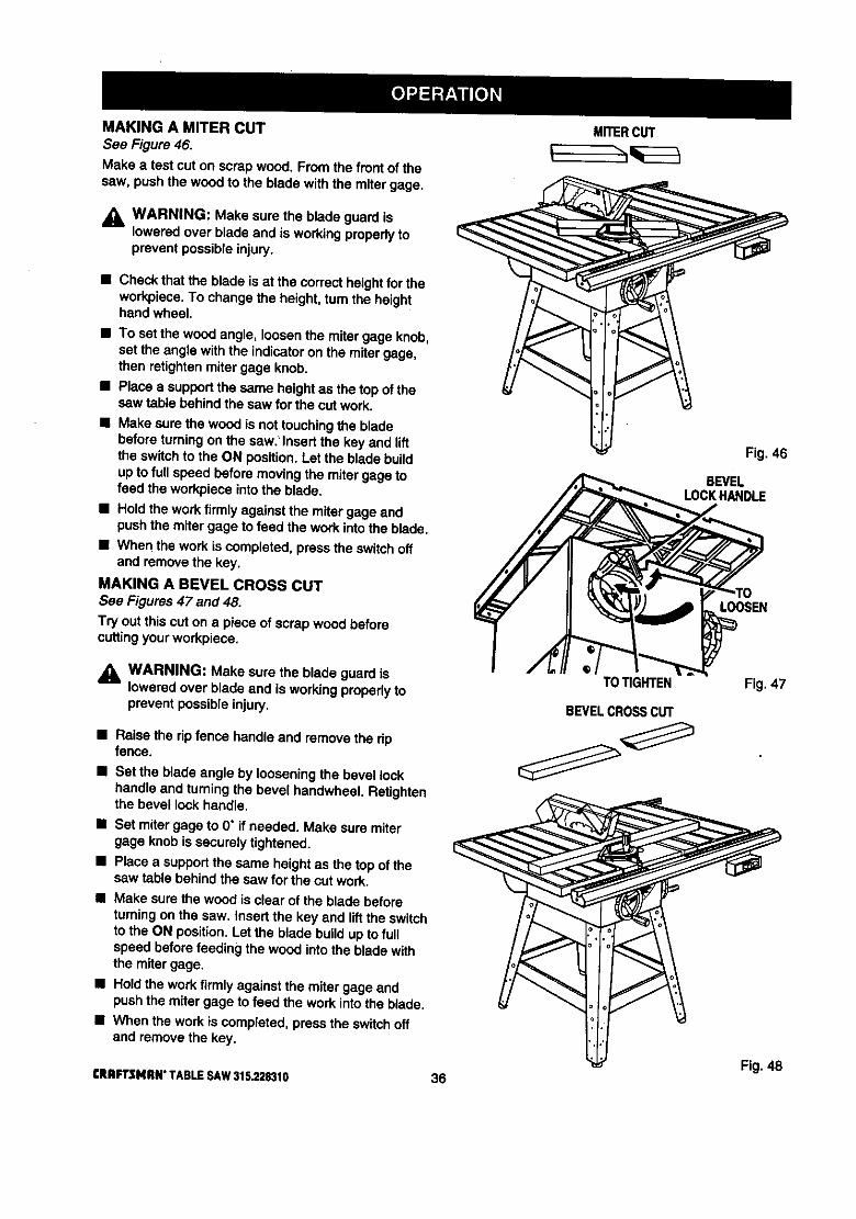
MAKINGA MITERCUTSee Figure 46.Make a test cut on scrap wood. From the front of thecaw. push the wood to the blade with the miter gage.
_1, WARNING: Make sure the blade guardisloweredover blade and is workingpropedy toprevent possible injury.
• Check that the blade is at the correct heightfor theworkpiece.To change the heighL turn the heighthand wheel.
• To set the wood angle, loosenthe mitergage knob,set the angle withthe indicatoron the mitergage,then retightenmitergage knob.
• Place a supportthe same heightas the top of thesaw table behind the saw for the cut work.
• Make surethe wood is nottouchingthe bladebefore turningon the saw.' Insert the key and liftthe switchto the ON position.Let the blade buildupto full speed before movingthe mitergage tofeed the workpieceintothe blade.
• Ho_dthe work firmly against the miter gage aodpushthe miter gage to feed the work intothe blade.
• When the workis completed, pressthe switchoffand remove the key,
MAKING A BEVEL CROSS CUTSee Figures47 and 48.
Try outthis cut on a piece of scrap wood beforecuttingyour workpiece.
_k WARNING: Make sure the blade guardisloweredover blade and is workingpropedy toprevent possibleinjury.
• Raise the rip fence handleand remove the ripfence.
• Set the blade angle by loosening the bevel lockhandle and turningthe bevel handwheel. Retightenthe bevel lockhandle.
• Set mitergage to 0" if needed. Make sure mitergage knob is securely tightened.
• Place a supportthe same heightas the top of thesaw table behind the saw for the cut work.
• Make sure the wood is clear of the blade beforeturningonthe saw. Insert the key and lift the switchto the ON position. Let the blade build up to fullspeed before feeding the wood into the blade withthe mitergage.
• Hold the workfirmlyagainst the miter gage andpushthe mitergage to feed the work intothe blade.
• When the work is completed, press the switchoffand removethe key.
CRBFT$141_#° TABLESAW315.228310 36
MITERCUT
TOTIGHTEN
BEVELCROSSCUT
Fig. 46
BEVELLOCKHANDLE
LOOSEN
Fig. 47
Fig. 48

MAKINGA BEVELRIPCUTSee Figure 49.
Try out thiscut on a piece of scrap wood beforecuttingyour workpiece. Use a pushstickto move smallpieces of wood into and past the blade.
_, WARNING: Make sure the blade guard isloweredover blade and is working propedy toprevent possibleinjury.
• Set the blade angle by loosening the bevel lockhandle and turningthe bevel handwheel. Retightenthe bevel lock handle.
,_k WARNING: When making a bevel rip cut, thedp fence must be on the rightside of the blade.Otherwise the fence could trap the workpiece,possiblycausing kickbackand resultingin injury.
• Attachthe dp fence on the 'dghtside of the blade atthe correctdistancefrom the blade forthe cut.
• Place a supportthe same heightas the top of thesaw table behindthe saw for the cut work.
_1= WARNING: Never stand directly in the line ofcut. Stand to the side to reduce the chance of
injury should kickback occur.
• Make surethe wood is clear of the blade beforeturningon the saw. Insert the key and lift the switchto the ON position.Let the blade obtain full speedbeforefeeding the workpiece intothe blade.
BEVELRIPCUT
Fig. 49
• Place the workfirmly againstthe ripfence and feedthe work intothe blade.
,_ WARNING: Never push a small pieceof woodinto the blade withyour hand. Use a pushstickasthe end of the workpiece nears the blade.
• When the work is completed, pressthe switchoffand removethe key.
37 CRAFTSMAN"TABLESAW315.228310
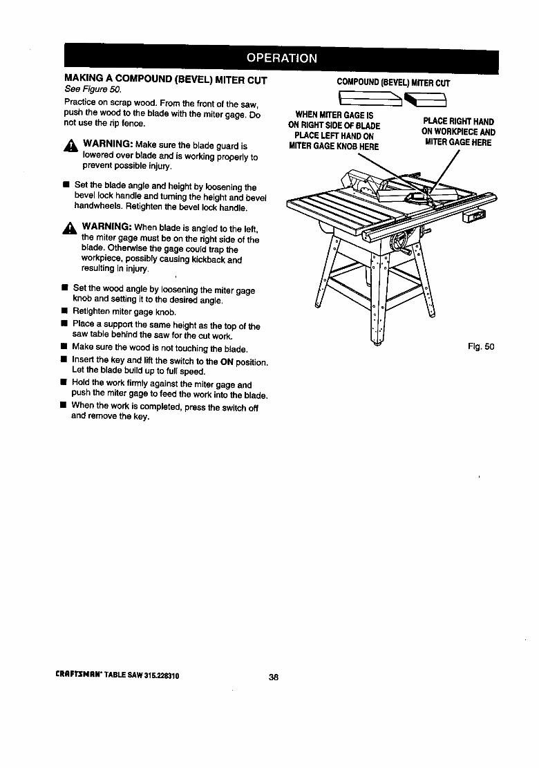
MAKING A COMPOUND (BEVEL) MITER CUTSea Figure 50.Practice on scrap wood. From the front of the sew,push the wood to the blade with the mitergage. Donot use the rip fence.
WARNING: Make sure the blade guard islowered overblade and is workingproperlytoprevent possible injury.
• Set the blade angle and heightby looseningthebevel lock handleand turningthe heightand bevelhandwheeis. Retightenthe bevel lockhandle.
,_ WARNING: When blade is angled to the left,the miter gage must be onthe dghtside of theblade. Otherwise the gage couldtrap theworkpiece, possiblycausingkickbackandresultingin injury.
• Set the wood angle by loosening the miter gageknob and settingit to the desiredangle.
• Retighten mitergage knob.
• Place a supportthe same heightas the top of thesaw table behind the saw for the cut work.
II Make surethe wood is nottouchingthe blade.• Insert the kay and lift the switchto the ON position.
Let the blade build upto full speed.
• Hold the work firmly against the mitergage andpush the miter gage to feed the workintothe blade.
• When the workis completed,press the switchoffand removethe key.
COMPOUND(BEVEL)MITERCUT
WHENMITERGAGEISONRIGHTSIDEOFBLADE
PLACELEFTHANDONMITERGAGEKNOBHERE
PLACERIGHTHANDONWORK,PIECEANDMITERGAGEHERE
Fig. 50
CRRFTSI4RN"TABLESAW315.228310 38
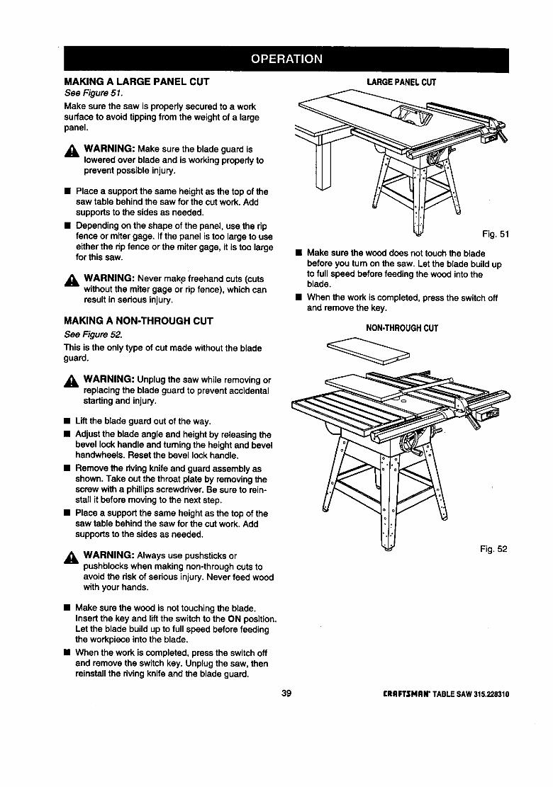
MAKING A LARGE PANEL CUT
See Figure 51.
Make sure the saw is properlysecured to a worksurfaceto avoid tipping from the weight of a largepanel.
_k WARNING: Make sure the blade guard islowered over blade and is working properly toprevent possibleinjury.
• Place a supportthe same heightas the top of thesaw table behind the saw for the cut work. Addsupportsto the sides as needed.
• Dependingon the shape of the panel, use the ripfence or miter gage. If the panel is too large to useeitherthe ripfence or the mitergage, it is too largefor thissaw.
_l, WARNING: Never makp freehand cuts (cutswithoutthe miter gage or ripfence), which canresult in seriousinjury.
MAKING A NON-THROUGH CUT
See Figure 52.
This is the only type of cut made withoutthe bladeguard.
,_, WARNING: Unplugthe saw while removingorreplacingthe blade guardto prevent accidentalstartingand injury.
• Lift the blade guard out of the way.
• Adjustthe blade angle and heightby releasingthebevel lockhandle and turningthe heightand bevelhandwheels. Reset the bevel lockhandle.
• Remove the rivingknife and guard assemblyasshown.Take outthe throat plate by removingthescrew witha phillipsscrewdriver.Be sure to rein-stall it before movingto the next step.
• Place a supportthe same heightas the top of thesaw table behind the saw for the cut work. Addsupportsto the sidesas needed.
,_ WARNING: Always use pushsticksorpushblockswhen making non-throughcuts toavoid the riskof seriousinjury.Never feed woodwith your hands.
LARGEPANELCUT
Fig. 51
• Make surethe wood does nottouch the bladebefore you turn on the saw. Let the blade buildupto full speed before feeding the wood intotheblade.
• When the work is completed,pressthe switchoffand remove the key.
NON_HROUGHCUT
Fig. 52
• Make sure the wood is nottouchingthe blade.Insert the key and lift the switchto the ON position.Let the blade build upto full speed before feedingthe workpiece intothe blade.
• When the workis completed, pressthe switchoffand removethe switchkey. Unplugthe saw, thenreinstallthe rivingknifeand the blade guard.
39 CRIIFTSMRN" TABLE SAW 315,228310

MAKING A DADO CUTSee Figure 53.
An optionaldado throat plate is required for thisprocedure. See the Accessoriessectionof thismanual and check withyour nearest Sears RetailStore. All blades and dado sets must be ratedat least5,000 RPM,
_L WARNING: Unplugthe saw before workingaround the blade. Accidentalstartingcouldcause serious injury.
• Take outthe throat plate by looseningthe screw.
• Remove the rivingknife and guardassembly,• Remove the blade.
• Mount the dado blade accordingto the instructionsprovidedwith it.
• Test the blade nutand blade washertightness.• Installoptionaldado thmat'plate.
• Plug in the saw and follow dado instructions.Always use pushstickswith dado cuts.
• When the workis completed, pressthe switchoffand remove the key.
• Unplug the saw and reinstallthe dvingknifeandblade guard.
• Reverse the firstsix stepsabove.
DADO CUT
Fig, 53
WARNING: Never putyour hands within3 in. ofthe blade when it is on or you could be seriouslyhurt.
CRIIFTSMAN" TABLE SAW 315.228310 40

GENERAL MAINTENANCE
_k WARNING: When servicing,use only identicalCraftsman replacement pads. Use of any otherpart may create a h_o.ardor cause productdamage.
WARNING: To prevent accidental startingthatcouldcause possibleserious personal injury,turn off the saw, remove the switch key, andunplugthe saw before working on the table saw.
• Remove sawdust from the rails, top surface, andinside of saw frequently.
• Clean plastic partswith a soft damp cloth. Do notuse any strongsolvents.
_, WARNING: Do not at any time let brake fluids,gasoline, petroleum-based products,penetratingoils, etc. contactplastic pads. They containchemicals that can damage, weaken or destroyplastic.
• Pedodicallyclean the table, rails, and dp fence withgum and pitch remover. Do not allow pitchtoaccumulate onthe saw.
• Apply a thin coat of paste wax to the table top sothe wood slides easily while cutting.
• Regularlycheck all nuts, bolts, screws, and beltsfor tightnessand condition.Make sure the throatplate is in goodcondition.
MOTOR / ELECTRICAL
• Frequently vacuum or blow out any sawdustfromthe motor.
_l, WARNING: If the power cordis worn, cut, ordamaged in any way, have it replaced immedi-ately by a qualifiedservice technicianat a Searsstore or repair center. Failure to do so couldresult in serious personalinjury.
WARNING: To avoid fireor electrocution,reassemble electric partswith only identicalCraftsman replacement pads. Reassembleexactly as originallyassembled.
This saw has been lubricatedat the factory priortoshipment.After extended use, you shouldinspect,clean, and lubricatethe areas shown inthe drawing.Clean before lubricatingwith a solvent recommendedfor gumand pitch removal. Lubricate with SAE no. 20or no. 30 engine oil.
See Figure 54.
• Table brackets.(a)• Bevel handwheel rod threads and knuckle. (b)
• Height handwheelthreads and trunnion.(c)
41
B

PROBLEM CAUSE SOLUTION
Sawdoesnotstart. 1. Motorcordorwallcordisnot 1. Pluginmotorcordorwallcord.pluggedin.
2. Circuitfuseisblown.
3. Cimuitbreakeristripped.
4. Cordorswitchisdamaged.
Sawisnoisywhenrunning.
Motorissloworweak.
Motoroverheats.
Motorstalls,blowsfuses,ortripscircuitbreakers.
1. Motor needs attention.
1. Voltage from source is low.
2. Windings are burnedout oropen.
3. Start switchis defective.
4. Circuit is overloaded with
appliances, lights, or othermotorS.
1. Motor is overloaded.
2. Du$$blade.
3. Sawdust insidesaw is blockingair flow.
1. Starter switchis defective.
2. Voltage from source is low.
3. Dull blade.
4. Fuses or circuitbreakers arewrong size or defective.
5, Feeding workplacetoo rapidly,
2. Replace circuitfuse.
3. Reset circuitbreaker.
4. Have the cord or switchre-placed at your nearest SearsService Center.
1. Have the motor checkedatyour nearest Sears ServiceCenter.
1. Request a voltage check fromthe power company.
2, Have the motor checkedatyour nearest Sears ServiceCenter.
3, Have the switch replaced.
4. Do not use other appliances ormotors on the same circuitwhen using the saw.
1. Request a voltage check fromthe power company.
2. Replace the blade.
3. Clean out the saw base.
1. Have the switch replaced.
2. Request a voltage check fromthe power company.
3. Replace the blade.
4. Replace fuses or circuitbreakers.
5. Feed work,piece into bladeslower.
CRIIFTSNRN"TABLESAW315.228310 42

PROBLEM CAUSE SOLUTION
Fuses or circuitbreakers openfrequently.
1. Motor is overloaded.
2. Fuses or circuitbreakers arewrongsize or defective.
1. Feed work more slowly.
2. Replace fuses or circuit break-ers,
3. Dull blade. 3. Replace the blade.
Saw vibrates excessively.
4. Start switchis defective.
1. Blade is warped.
4. Have the switchreplaced.
1. Replace the blade.
2. Belt is damaged, 2. Replace the belt.
3. Saw is not mountedsecurely. 3, Tighten all hardware.
4. Work surface is uneven. 4. Repositionon a flat surface. Ad-justthe leveling feet on legs.
Start switchdoes not operate. 1. Switch contactsare burned out. 1. Have the switchreplaced andre-quest a voltage check from thepower company.
2. Capacitor is defective 2. Have the capacitor replaced.
3. Connectionsare loose or dam- 3. Have the widngchecked and re-aged. paired.
Handwheels are hard to turn. 1. Sawdust has collected on the 1. Clean and lubricate the mecha-mechanism insidesaw. nism.
Blade does not lower when turningheighthandwheel.
1. Blade lock handle is not fully 1. Fully release the blade lockreleased, handle.
Mitergage doesnotmovesmoothly. 1. Miter gage assembly is dirty or 1. Release the mitergage knobandsticky, wax the miter gage base _and
sides.
Cutbinds,bumsorstallsmotorwhenripping.
1. Blade orteeth are dull,
2. Blade is heeling.
1. Sharpen or replace the blade.
2. See Hee/ingtheSawbladeintheAdjustmentssection.
3. Board is warped. 3. Replace the board.
4. Ripfencedoesnotparallelblade. 4. SeeAligningtheRipFenceintheAssembly section.
Saw bladedoes notcut trueat 90"or 1.45" positions.
2.
Indicators are not properly ad-justed.
Positive stops inside base arenotaccurate.
1. See Setting the Bevel Stops andIndicatorinthe Adjustmentssec-tion.
2. See Setting the Bevel Stops andIndicatorinthe Adjustmentssec-tion.
43 CRAFTSMRN"TABLESAW315.228310

PROBLEM CAUSE SOLUTION
Rip fence does not move smoothly. 1. Rip fence is not mounted cor-rectly.
1. Remove and repositionthe ripfence. See AligningRip Fenceand Front Rail in the Assemblysection.
2. Rails are dirty or sticky. 2. Clean and wax the mils.
Wood edges away from rip fencewhen ripping.
1. Rip fence is misaligned. 1. See the Assembly section forChecking Rip Fence and BladeAlignmentand AligningRipFence and Front Railprocedures.
CRIIFTSMlU4"TABLESAW3_G.22834,0 44

45 CRRFTSMAN" TABLE SAW 315.228310

CRAFTSMAN TABLE SAW - MODEL NO. 315.228310
I The model number will be found on a plate attached to the cabinet. Always mention the model !numberin all correspondenceregarding your TABLE SAW or when ordering repairpads. I
12
FIGURE A
CRIIFTSMRN" TABLE SAW 315.228310 46

CRAFTSMAN TABLE SAW - MODEL NO. 315.228310
I The model number will be found on a plate attached to the cabinet. Always mention the model Inumber in all correspondenceregardingyour TABLE SAW or when ordering repair parts. I
PARTS LIST FOR FIGURE A
KEY PARTNO. NUMBER DESCRIPTION QUAN.
1 977481-001
2 979974-001
3 ** STD551031
4 979976-001
5 ** STD511O03
6 ** STD55t010
7 979978-001
8 979979-001
9 979980-001
10 979981-001
11 979984-001
12 ** STD511007
13 ** STD541010
End Cap ......................................................................................... 1
Miter Gage Knob (Includes Key No. 1) ......................................... 1
* Washer (5/16 in.) ........................................................................... 1
Miter Gage ..................................................................................... 1
* Screw (3/16-24 x 3/8 in.) ............................................................... 3
* Washer (3/16 in.) ........................................................................... 1
Miter Scale Indicator...................................................................... 1
Miter Gage Block........................................................................... 1
Stop Pin ......................................................................................... 1
Miter Gage Rod .................. .,.......................................................... 1
Shoulder Screw ............................................................................. 1
* Screw (3/16-24 x 3/4 in.) ............................................................... 3
* Hex Nut (3/16-24) .......................................................................... 3
• Standard Hardware Item -- May Be Purchased Locally** Available From Div. 98 -- Source 980.00
47 CRAFTSMAN"TABLESAW315.228310

i.-I:D.l:U
m(n
o
FIGUREBk
CRAFTSMAN TABLE SAW - MODEL NO. 315.228310
The model numberwill be foundona plate attached to the cabinet.Alwaysmentionthe model numberinall correspondenceregardingyour TABLE iSAW orwhen orderingrepair parts. J
3

CRAFTSMANTABLE SAW- MODELNO.315.228310
I he model numberwill be foundona plate attached to the cabinet.Alwaysmentionthe model numberinall correspondenceregardingyour TABLE JSAW or when orderingrepair parts. I
(o
mrf11
=E
,e.
PARTS LIST FOR FIGURE B
KEY PARTNO. NUMBER DESCRIPTION QUAN.
1 979999-001
2 ** STD541031
3 ** STD551031
4 979995-001
5 979994-001
6 979993-001
7 979997-001
8 979888-001
9 979996-001
10 979998-001
11 980315-001
Leveling Foot..................................................................................................................................................... 4
* Hex Nut (5/16-18) ........................................................................................................................................... 36
* Washer (5/16 in.)............................................................................................................................................. 40
Leg .................................................................................................................................................................... 4
* Carriage Bolt(5/16-18 x 3/4 in.)...................................................................................................................... 24
End Brace ......................................................................................................................................................... 2
Side Brace ......................................................................................................................................................... 2
* Bolt(5/16-18 x 1/2 in. Hex Hd.) ........................................................................................................................ 4
Short Leg Brace ................................................................................................................................................ 2
Long Leg Brace ................................................................................................................................................. 2
Logo Plate ......................................................................................................................................................... 1
*Standard Hardware Item -- May Be Purchased Locally**Available From Div. 98 -- Source 980.00

i¢,m
o
O1O
CRAFTSMAN TABLE SAW - MODEL NO. 315.228310
I he model numberwillbe foundon a plateattached to the cabinet.Always mentionthe model numberin all correspondenceregardingyour TABLE !SAW or when orderingrepair parts. I
24'
21
10
11
25
1314
17
FIGUREC

ial
CRAFTSMAN TABLE SAW- MODEL NO, 315.228310
I The model numberwillbe foundon a plate attached to the cabinet. Always mention the model number in all correspondence regarding your TABLE |
I
SAW or when ordering repair parts. I
PARTS LIST FOR FIGURE CKEY PART KEY PARTNO. NUMBER DESCRIPTION QUAN. NO. NUMBER DESCRIPTION QUAN.
1 979973-001
2 979945-001
3 ** STD541425
4 979970-001
5 979969-001
6 979968-001
7 979972-001
8 ** STD551008
9 979961-001
10 979962-001
11 979963-001
12 979881-001
13 979964-001
Fence End Cap ...................................... 1
* Screw (5/32-32 x 1/2 in.) ....................... 4
* Lock Nut (1/4-20) ................................... 1
Lock Plate .............................................. 1
Lock Spdng ............................................ 1
Fence Lock Rod .................................... 1
Rear Fence Slide ................................... 1
* Washer (5/32 in.) ................................... 1
Scale Indicator ....................................... 1
Fence Plate ........................................... 1
Rip Fence Cover .................................... 1
* Screw (5/16-18 x 1/2 in. Socket Hd.) .... 4
Fence Handle Bracket ........................... 1
14 980964-001
15 980596-001
16 980596-001
17 979965-001
18 979966-001
19 979967-001
20 980966-001
21 980598-001
22 980965-001
23 979960-001
24 979959-001
25 980322-001
26 980317-001
Cam Sleeve ........................................... 1
Pin .......................................................... 1
Retaining Ring ....................................... 2
Rip Fence Handle .................................. 1
Roll Pin (8 x 40 mm) .............................. 2
Screw (1/4-20 x 3/4 in. Socket Hal.) ...... 4
Rear Glide ............................................. 2
Screw (5/32-32 x 3/8 in.) ....................... 4
Front Glide ............................................. 2
Scale Indicator Housing ........................ 1
Rip Fence .............................................. 1
Waming Label ........................................ 1
Fence Label ........................................... 1
• *Standard Hardware Item -- May Be Purchased Locally**Available From Div. 98 -- Source 980.00
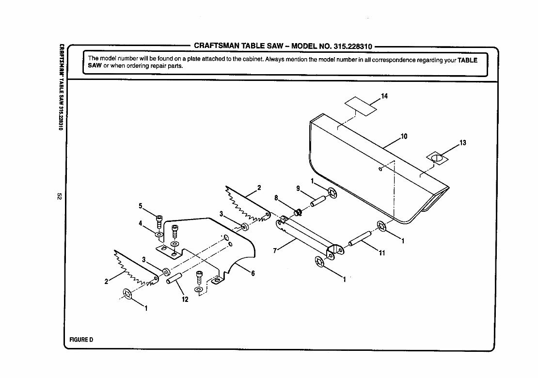
iO1I%1
CRAFTSMAN TABLE SAW - MODEL NO. 315.228310
I The model numberwill be found ona plateattachedto the cabinet.Always mentionthe modelnumberin allcorrespondenceregardingyour TABLE ISAW or when ordering repair parts. !
FIGURED
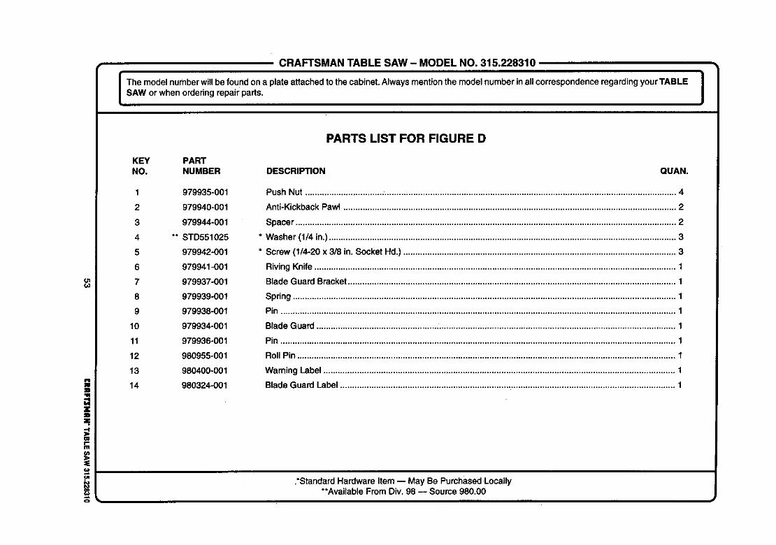
CRAFTSMAN TABLE SAW- MODEL NO. 315.228310
The modelnumberwillbe foundona plateattached tothe cabinet.Always mentionthe modelnumberin allcorrespondenceregardingyourTABLE JSAW or when orderingrepair parts. I
ol€.o
=W
W
111
o
PARTS LIST FOR FIGURE D
KEY PARTNO. NUMBER DESCRIPTION QUAN.
1 979935-001
2 979940-001
3 979944-001
4 ** STD551025
5 979942-001
6 979941-001
7 979937-001
8 979939-001
9 979938-001
10 979934-001
11 979936-001
12 980955-001
13 980400-001
14 980324-001
Push Nut .......................................................................................................................................................... 4
Anti-KickbackPawl .......................................................................................................................................... 2
Spacer .............................................................................................................................................................. 2
Washer (1/4 in.)................................................................................................................................................ 3
Screw (1/4-20 x 3/8 in. Socket Hd.) ................................................................................................................. 3
Riving Knife...................................................................................................................................................... 1
Blade Guard Bracket........................................................................................................................................ 1
Spring............................................................................................................................................................... 1
Pin .................................................................................................................................................................... 1
Blade Guard .................................................. :.................................................................................................. 1
Pin .................................................................................................................................................................... 1
RollPin ............................................................................................................................................................. 1
Warning Label .................................................................................................................................................. 1
Blade Guard Label ........................................................................................................................................... 1
.*StandardHardware Item-- May Be Pumhased Locally**Available From Div. 98 -- Source 980.00
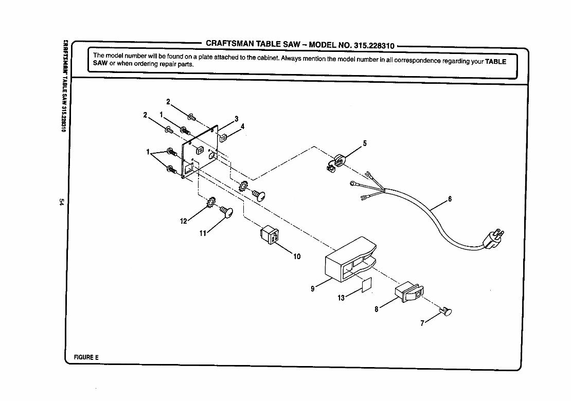
ol4==
CRAFTSMAN TABLE SAW - MODEL NO. 315.228310
The modelnumberwill be foundona plate attachedto the cabinet.Always mentionthe modelnumberin allcorrespondenceregardingyourTABLE ISAW orwhen orderingrepair parts. I
11
FIGUREEi I
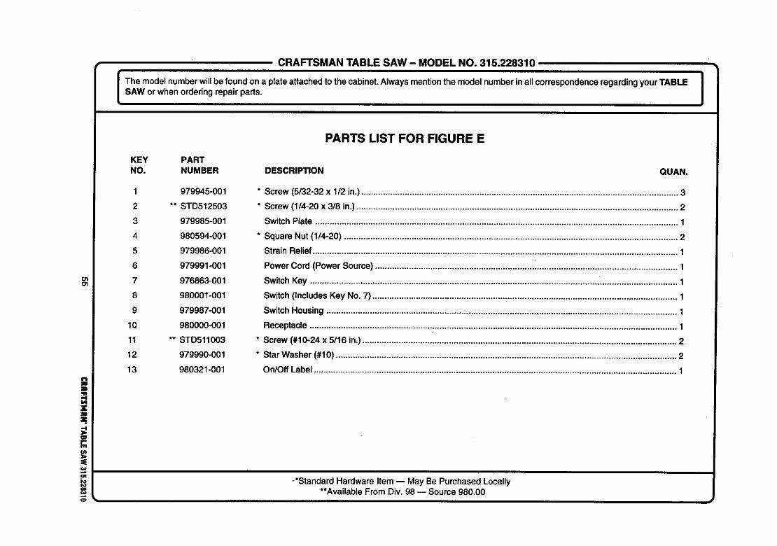
CRAFTSMAN TABLE SAW - MODEL NO. 315.228310
I The model number willbe foundon a plate attachedto the cabinet.Always mentionthe model numberinall correspondenceregardingyour TABLE I
I
SAW or when orderingrepair parts. I
otO1
=.
tJt
o
PARTS LIST FOR FIGURE E
KEY PARTNO. NUMBER DESCRIPTION QUAN.
1 979945-001
2 ** STD512503
3 979985-001
4 980594-001
5 979986-001
6 979991-001
7 976863-001
8 980001-001
9 979987-001
10 980000-001
11 ** STD511003
12 979990-001
13 980321-001
* Screw (5/32-32 x 1/2 in.)................................................................................................................................... 3
* Screw (1/4-20 x 3/8 in.)..................................................................................................................................... 2
Switch Plate ...................................................................................................................................................... 1
* Square Nut (1/4-20) .......................................................................................................................................... 2
Strain Relief....................................................................................................................................................... 1
PowerCord (Power Source) ............................................................................................................................. 1
SwitchKey ........................................................................................................................................................ 1
Switch(Includes Key No. 7) .............................................................................................................................. 1
SwitchHousing ................................................................................................................................................. 1
Receptacle ........................................................................................................................................................ 1
* Screw (#10-24 x 5/16 in.).................................................................................................................................. 2
* Star Washer (#10) ............................................................................................................................................. 2
On/Off Label ...................................................................................................................................................... 1
-*Standard Hardware Item -- May Be Purchased Locally**Available From Div. 98 -- Source 980.00
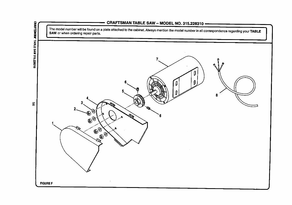
OlCb
CRAFTSMAN TABLE SAW - MODEL NO. 315.228310
I The model numberwillbe foundon a plateattached to the cabinet.Always mention the model numberin allcorrespondence regarding your TABLE |
I
SAW or when orderingrepair parts. I
6
FIGUREF
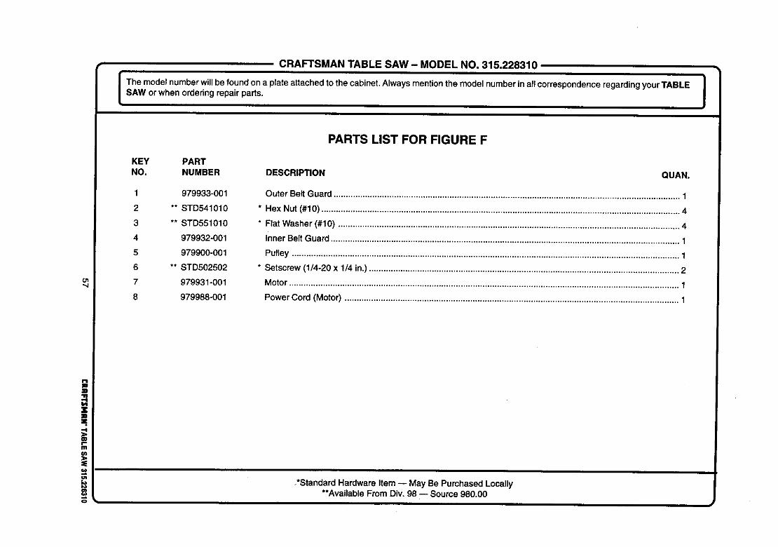
CRAFTSMAN TABLE SAW- MODEL NO. 315.228310
em°0ew °'° ° e °0enum °°c°0°0 0Is,worw ono°e00
ol
Wf,.m
P_
KEY PARTNO. NUMBER DESCRIPTION
1
2
3
4
5
6
7
8
979933-001
** STD541010
** STD551010
979932-001
979900-001
** STD502502
979931-001
979988-001
PARTS LIST FOR FIGURE F
QUAN.
Outer Belt Guard ............................................................................................................................................... 1
* Hex Nut (#10) .................................................................................................................................................... 4
* Flat Washer (#10) ............................................................................................................................................. 4
Inner Belt Guard ................................................................................................................................................ 1
Pulley ................................................................................................................................................................ 1
* Setscrew (1/4-20 x 1/4 in.) ................................................................................................................................ 2
Motor................................................................................................................................................................. 1
Power Cord (Motor) .......................................................................................................................................... 1
,*Standard Hardware Item -- May Be Purchased Locally**Available From Div. 98 -- Source 980.00
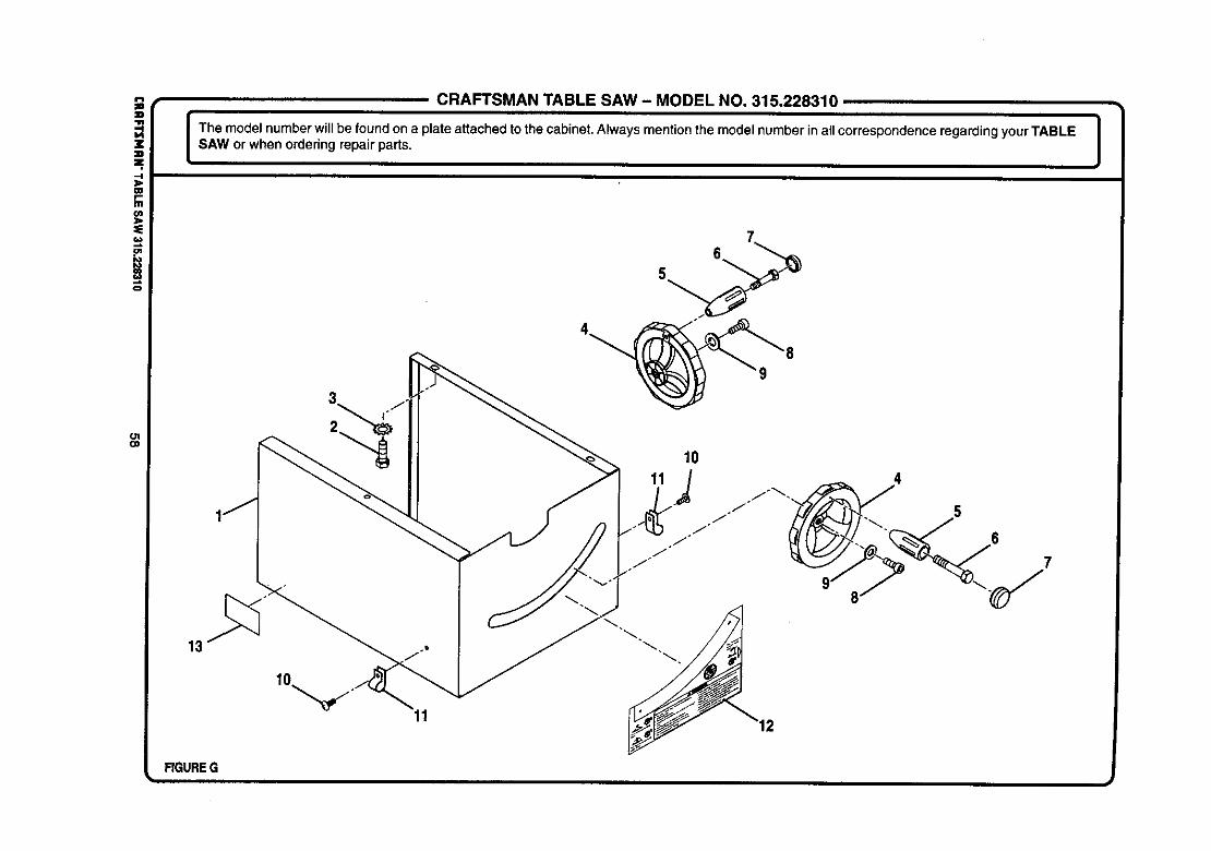
io
OlO1
CRAFTSMAN TABLE SAW - MODEL NO. 315.228310
The model number willbe found on a plate attached to the cabinet. Always mention the model number inall correspondence regarding your TABLE |SAW or when ordering repair parts. I
17
FIGUREG
11
65

CRAFTSMANTABLE SAW- MODELNO.315.228310
The model number will be foundon a plate attached to the cabinet.Always mentionthe model numberin allcorrespondenceregardingyourTABLE |SAW or when orderingrepair parts. I
Ol(D
i=.
CDr"Ill
PARTS LIST FOR FIGURE G
KEY PARTNO. NUMBER DESCRIPTION QUAN.
1 979992-001
2 ** STD523105
3 980588-001
4 979918-001
5 977229-001
6 977491-001
7 977481-001
8 980602-001
9 ** STD551010
10 ** STD511005
11 980599-001
12 980320-001
13 980325-001
Base .................................................................................................................................................................. 1
* Bolt (5/16-18 x 1/2 in. Hex Hd.) ........................................................................................................................ 3
* Star Washer (5/16 in.) ....................................................................................................................................... 3
Handwheel Assembly (Includes Key Nos. 5, 6, and 7) ..................................................................................... 2
Handle ............................................................................................................................................................... 2
Screw (M8 x 1.25 in.) ........................................................................................................................................ 2
End Cap ............................................................................................................................................................ 2
* Screw (3/16-24 x 1/2 in. Socket Hd.) ................................................................................................................ 2
* Washer (#10) .................................................................................................................................................... 2
* Screw (#10) ....................................................................................................................................................... 2
Cord Clip ........................................................................................................................................................... 2
Bevel Scale Label ............................................................................................................................................. 1
Data Plate ......................................................................................................................................................... 1
•*Standard Hardware Item -- May Be Purchased Locally**Available From Div. 98 -- Source 980.00

!¢3
o_o
CRAFTSMAN TABLE SAW- MODEL NO. 315.228310
I Them_de_numberwi'_bef_und_nap_ateattachedt_thecabinet_A_waysmenti_nthem_de_numberina__c_rresp_ndencer_gardingy_urTABLE_sAwor when orderingrepair parts.
2
FIGUREHi

CRAFTSMAN TABLE SAW- MODEL NO. 315.228310
The model numberwillbe found on a plateattachedto the cabinet.Always mentionthe modelnumberin allcorrespondenceregardingyour TABLE iSAW or when orderingrepair parts. I
i"4
O_
=E
f.w
io
o
PARTS LIST FOR FIGURE H
KEY PARTNO. NUMBER DESCRIPTION QUAN.
1 979945-001
2 979946-001
3 979947-001
4 979948-001
5 979870-001
6 979956-001
7 979950-001
8 979951-001
9 979949-001
10 979879-001
11 ** STD523112
12 ** STD551131
13 ** STD541031
14 979873-001
15 79871-001
16 979872-00_
17 979869-001
18 979974-001
19 979875-001
20 980323-001
* Screw (5/32-32 x 1/2 in.)................................................................................................................................... 4
End Cap (Left Rear) .......................................................................................................................................... 1
Real Rail ........................................................................................................................................................... 1
End Cap (Right Rear) ....................................................................................................................................... 1
Extension Table ................................................................................................................................................. 2
Scale ................................................................................................................................................................. 1
Front Rail (Includes Key No. 6) ......................................................................................................................... 1
End Cap (Right Front) ....................................................................................................................................... 1
End Cap (Left Front) ......................................................................................................................................... 1
* Bolt (5/16-18 x 1 in. Square Hd.) .................................................................................................................... 12
* Bolt (5/16-18 x 1-1/4 in. Hex Hd.) ..................................................................................................................... 8
* Washer (5/16 in.) ............................................................................................................................................. 28
* Hex Nut (5/16-18) ........................................................................................................................................... 20
* Setscrew (3/16-24 x 3/16 in.) ............................................................................................................................ 4Throat Plate ....................................................................................................................................................... 1
* Screw (3/16-24 x 3/4 in.) ........................................................... i ....................................................................... 1
Saw Table .......................................................................................................................................................... 1
* Setscrew (5/16-18 x 5/8 in.) .............................................................................................................................. 2
Align-A-Cut Insert .............................................................................................................................................. 1Label ................................................................................................................................................................. 1
• *Standard Hardware Item -- May Be Purchased Locally**Available From Div. 98 -- Source 980.00
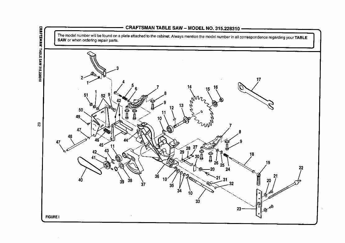
i(J1
,e.o
o')Po
CRAFTSMAN TABLE SAW - MODEL NO. 315.228310
I he model numberwill be foundon a plate attachedto the cabinet.Alwaysmentionthe model numberinall correspondenceregardingyour TABLE ISAW or when ordering repairparts. I
50
151
49,
47
4847
12
1t 15 16
7
17
4036
3837 35
34 10
33
IB
1922
FIGURE I
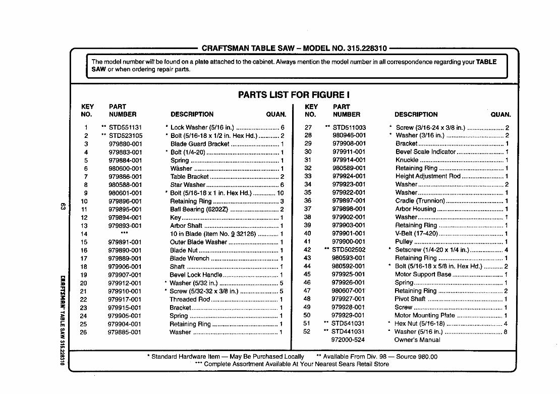
CRAFTSMAN TABLE SAW - MODEL NO. 315.228310
I The model numberwillbe foundon a plate attachedto the cabinet.Alwaysmentionthe modelnumber inall correspondenceregarding yourTABLE I
I
SAW or when ordedngrepair pads. I
o)
zIIz-4
OIr-I11u)
Io€o
o
KEY PARTNO. NUMBER DESCRIPTION QUAN.
1 ** STD5511312 ** STD5231053 979880-0014 979883-0015 979884-0016 980600-0017 979886-0018 980588-0019 980601-001
10 979896-00111 979895-00112 979894-00113 979893-00114 ***15 979891-00116 979890-00117 979889-00118 979906-00119 979907-00120 979912-00121 979910-00122 979917-00123 979915-00124 979905-00125 979904-00126 979885-001
PARTS LIST FOR FIGURE I
KEY PART
* Lock Washer (5/16 in.) ......................... 6* Bolt (5/16-18 x 1/2 in. Hex Hd.) ............ 2
Blade Guard Bracket ............................ 1
* Bolt (1/4-20) .......................................... 1Spdng ................................................... 1Washer ................................................. 1Table Bracket ........................................ 2Star Washer .......................................... 6
* Bolt (5/16-18 x 1 in. Hex Hd.) ............. 10Retaining Ring ...................................... 3Ball Beadng (8202Z) ............................ 2Key ........................................................ 1Arbor Shaft ........................................... 1
10 in Blade (Item No. 9 32126) ............ 1Outer Blade Washer ............................. 1Blade Nut .............................................. 1Blade Wrench ....................................... 1Shaft ..................................................... 1Bevel Lock Handle ................................ 1
* Washer (5/32 in.) .................................. 5* Screw (5/32-32 x 3/8 in.) ...................... 5
Threaded Rod ....................................... 1Bracket .................................................. 1
Spring ................................................... 1Retaining Ring ...................................... 1Washer ................................................. 1
NO. NUMBER DESCRIPTION QUAN.
27 ** STD51100328 980946-001
29 979908-001
30 979911-001
31 979914-001
32 980589-001
33 979924-001
34 979923-001
35 979922-001
36 979897-001
37 979898-001
38 979902-001
39 979903-001
40 979901-001
41 979900-001
42 ** STDS02502
43 980593-001
44 980592-001
45 979925-001
46 979926-001
47 980607-001
48 979927-001
49 979928-001
50 979929-001
51 ** STD541031
62 ** STD441031
972000-524
* Screw (3/16-24 x 3/8 in.) ..................... 2* Washer (3/16 in.) ................................. 2
Bracket ................................................. 1Bevel Scale Indicator ........................... 1Knuckle ................................................ 1
Retaining Ring ..................................... 1Height Adjustment Rod ........................ 1Washer ................................................. 2Washer ................................................. 1Cradle (Trunnion)................................. 1Arbor Housing ...................................... 1Washer ................................................. 1
Retaining Ring ..................................... 1V-Belt (17-420) ..................................... 1Pulley ................................................... 1
* Setscrew (1/4-20 x 1/4 in.) ................... 4Retaining Ring ..................................... 1
* Bolt (5/16-18 x 5/8 in. Hex Hd.) ........... 2Motor Support Base ............................. 1Spring ................................................... 1Retaining Ring ..................................... 2Pivot Shaft ........................................... 1Screw ................................................... 1Motor Mounting Plate .......................... 1
* Hex Nut (5/16-18) ................................ 4* Washer (5/16 in.) ................................. 8
Owner's Manual
* Standard Hardware Item -- May Be PurchasedLocally ** Available From Div. 98 -- Source 980.00*** Complete AssortmentAvailableAt Your Nearest Sears Retail Store

For in-home major brand repair service:
Call 24 hours a day, 7 days a week
1-800-4-MY-Home s" (1-800-469-4663)
Para pedir servicio de reparaci6n a domicilio - 1-800-676-5811
In Canada for all your service and parts needs call _ 1-800-665-4455Au Canada pour tout le service ou les pi_ces
For the repair or replacement parts you need:
Call 7 am - 7 pro, 7 days a week
1-800-366-PART (1-800-366-7278)
Para ordenar piezas con entrega a domicilio - 1-800-659-7084
For the location of a Sears Parts and Repair Center in your area:
Call 24 hours a day, 7 days a week
1-800-488-1222
For information on purchasing a Sears Maintenance Agreementor to inquire about an existing Agreement:
Call 9 am - 5 pro, Monday - Saturday
1-800-827-6655
I
The Service Side of Sears"