Owner's Manual · a. Use No.10 AWG (5.3mm2) copper, No.8 AWG (8.4mm2) aluminum, No.17 AWG (1.0mm 2)...
43
BW AUTO 6.0 4.0 2.3 1.8 0.5 MODE AM SYNC LSB USB CW FM RTTY SCAN MEM LIST A-B SEEK TIME CARR MEM TUNE VFO A = B A = B PRE ATTN ANT 1 2 VHF AGC S F NOTCH NB N W NAME 12 ON OFF TIMER STEP CLK/FREQ LOCK TUNE SCAN NOTCH TONE SCAN MEM 6.0 4.0 AM/ SYNC FM 2.3 1.8 LSB USB 0.5 AUTO CW RTTY BANDWIDTH MODE LIST 2 A - B 3 SEEK 4 TIME 5 CARR 6 CLK 7 LAMP 8 BEEP 9 F DEL 0 V M M V SQUELCH PASSBAND OFFSET VOL RF MIN 0 - + R8A Communications Receiver 1 3 5 7 9 20 40 60 S UNITS DECIBLES SIGNAL M/KHz MEM 1 CLR F kHz MHz R8A Communications Receiver Owner's Manual ® © Copyright 1997 R. L. Drake Company P/N: 3851299H-1-1997 Printed in the U. S. A. is a registered trademark of the R. L. Drake Company ®
Transcript of Owner's Manual · a. Use No.10 AWG (5.3mm2) copper, No.8 AWG (8.4mm2) aluminum, No.17 AWG (1.0mm 2)...

BW
AUTO
6.0 4.0
2.3 1.8
0.5
MODE
AM SYNC
LSB USB
CW FM
RTTY
SCAN
MEM
LIST
A-B
SEEK
TIME
CARR
MEM
TUNE
VFO A = B
A = B
PRE ATTN
ANT 1 2 VHF
AGC S F
NOTCH
NB N W
NAME
12 ON OFF
TIMER
STEP
CLK/FREQ
LOCK
TUNE
SCAN
NOTCH
TONE
SCAN
MEM
6.0
4.0
AM/
SYNC
FM
2.3
1.8
LSB
USB
0.5
AUTO
CW
RTTY
BANDWIDTH
MODE
LIST
2
A - B
3
SEEK
4
TIME
5
CARR
6
CLK
7
LAMP
8
BEEP
9
F
DEL
0
V M
M V
SQUELCH
PASSBAND
OFFSET
VOL
RF
MIN
0
-
+
R8A Communications Receiver
1 3 5
7
9 20 4
0 60
S UNITS
DECIBLES
SIGNAL
M/KHz
MEM
1
CLR
F
kHzMHz
R8A Communications Receiver
Owner's Manual
®
© Copyright 1997 R. L. Drake Company P/N: 3851299H-1-1997 Printed in the U. S. A.
is a registered trademark of the R. L. Drake Company®

Date: October 16, 1995 Signature ___________________
Ref. No. 953427 Name: G. Raithel Dipl.-Ing.
Signature ____________________
Date: January 01, 1997 Name: Ronald E. Wysong____(Stamp)®
Declaration of ConformityWe, Manufacturer/Importer
(Full address)R. L. Drake Company230 Industrial Drive
Franklin, Ohio 45005 United States of America
declare that the product(Description of the apparatus, system, installation to which it refers)
R8A Communications Receiver1293
is in conformity with(reference to the specifications under which conformity is declared)
in accordance with 89/336 EEC-EMC Directive
EN 55011
EN 55013
EN 55014
EN 55015
EN 55020
EN 55022
DIN V VDE 0855part 10part 12
CE marking
EN 60065
Cabled distribution systems; Equipmentfor receiving and/or distribution fromsound and television signals
Limits and methods of measurementof radio disturbance characteristics ofindustrial, scientific and medical (ISM)high frequency equipment
Limits and methods of measurementof radio disturbance characteristics ofbroadcast receivers and associatedequipment
Limits and methods of measurementof radio disturbance characteristics ofhousehold electrical appliances,portable tools and similar electricalapparatus
Limits and methods of measurementof radio disturbance characteristics offlourescent lamps and luminaries
immunity from radio interference ofbroadcast receivers and associatedequipment
Limits and methods of measurementof radio disturbance characteristics ofinformation technology equipment
Disturbances in supply systems causedby household appliances and similarelectrical equipment "Harmonics"
Disturbances in supply systems causedby household appliances and similarelectrical equipment "Voltage fluctuations"
Generic emission standard
Generic immunity standard
EN 61000-3-2*
EN 61000-3-3*
EN 50081-1
EN 50082-1
prEN 55024-2
prEN 55024-3
pr EN 55024-4
prENV 50142
ENV 50141
Electrostatic discharge requirements"ESD" (IEC 801-2)
Radiated, radio frequency electromagneticfield (IEC 801-3)
Electrical fast transient requirements"Burst" (IEC 801-4)
Surge immunity requirements(IEC 801-5)
Immunity to conducted disturbancesinduced by radio frequency fieldsabove 9kHz (IEC 801-6)
* Replacement of EN60555-2/-3
Safety requirements for mains operatedelectronic and related apparatus forhousehold and similar general use
The manufacturer also declares the conformity of above mentioned productwith the actual required safety standards in accordance with LVD 73/23 EEC.
(EC conformity marking)
Manufacturer/Importer
EN 60950 Safety for information technology equipmentincluding electrical business equipment
EMC Tested by electronic GmbH

1 Important Safeguards
TO REDUCE THE RISK OF FIRE OR ELECTRIC SHOCK, DO NOT EXPOSE THIS APPLIANCETO RAIN OR MOISTURE.DO NOT OPEN THE CABINET, REFER SERVICING TO QUALIFIED PERSONNEL ONLY.
TO PREVENT ELECTRIC SHOCK, DO NOT USE THE THREE WIRE CORD WITH AN EXTENSIONCORD RECEPTACLE OR OTHER OUTLET UNLESS THE BLADES CAN BE FULLY INSERTED TOPREVENT BLADE EXPOSURE.
POUR PREVENIR LES CHOCS ELECTRIQUES, NE PAS UTILISER CETTE FICHE POLARISEEAVEC UN PROLONGATEUR, UNE PRISE DE COURANT OU UNE AUTRE SORTIE DE COUR-ANT, SAUF SI LES LAMES PEUVENT ETRE INSEREES A FOND SANS EN LAISSER AUCUNEPARTIE A DECOUVERT.
WARNING:
CAUTION:
ATTENTION:
An appliance and cart combination should be movedwith care. Quick stops, excessive force and unevensurfaces may cause the appliance and cart combina-tion to overturn.
The lightning flash with arrow head symbol, within anequilateral triangle, is intended to alert the user to thepresence of uninsulated "dangerous voltage" withinthe product's enclosure that may be of sufficientmagnitude to constitute a risk of electric shock topersons.
The exclamation point within an equilateral triangle isintended to alert the user to the presence of impor-tant operating and maintenance (servicing) instruc-tions in the literature accompanying the appliance.
¡WARNING!
WARNING: TO PREVENT FIRE ORELECTRICAL SHOCK DO NOT
EXPOSE TO RAIN OR MOISTURE
RISK OF ELECTRIC SHOCKDO NOT OPEN
WARNING: TO REDUCE THE RISK OF ELECTRICSHOCK,
DO NOT REMOVE COVER (OR BACK)NO USER-SERVICABLE PARTS INSIDE
REFER SERVICING TO QUALIFIED PERSONNEL
1. Read Instructions —All the safety and operating instructions should be
read before the appliance is operated.
2. Retain Instructions —The safety and operating instructions should be
retained for future reference.
3. Heed Warnings —All warnings on the appliance should be adhered to.
4. Follow Instructions —All operating and use instructions should be
followed.
5. Cleaning —Unplug this appliance from the wall outlet before cleaning.
Do not use liquid cleaners or aerosol cleansers. Use a damp cloth for
cleaning.
6. Do Not Use Attachments —not recommended by the manufacturer or
they may cause hazards.
7. Water and Moisture —Do not use this product near water—for example,
near a bathtub, wash bowl, kitchen sink, laundry tub, in a wet basement,
or near a swimming pool—and the like.
8. Accessories —Do not place this product on an unstable cart, stand,
tripod, bracket, or table. The product may fall, causing serious injury to a
child or adult, and serious damage to the appliance.
9. Ventilation —This product should never be placed near or over a
radiator or heat register. This product should not be placed in a built-in
installation such as a bookcase or rack unless proper ventilation is provided
or the manufacturer’s instructions have been adhered to. Any slots or
openings in the cabinet are provided for ventilation. To ensure reliable
operation of the video product and to protect it from overheating, these
openings must not be blocked or covered. The openings should never be
blocked by placing the product on a bed, sofa, rug, or other similar surface.
10. Grounding or Polarization —This product is equipped with a 3- wire
line cord receptacle. It is intended for use with a 3-wire properly grounded
power socket. Do not defeat the safety purpose of the supplied line cord
and plug.
10A. Mise à la terre ou Polarisation —Cet appareil est équipé avec un
cordon d'alimentation à trois fils. Il est a brancher sur une prise ayant un
connecteur a la terre. Assurez-vous que la connection a la terre ne manque
pas.
11. Power Sources —This product should be operated only from the type
of power source indicated on the marking label. If you are not sure of the
type of power supplied to your home, consult your appliance dealer or local
power company.
12. Power-cord Protection —Power-supply cords should be routed so
they are not likely to be walked on or pinched by items placed upon or
against them. Pay particular attention to cords at plugs, convenience
receptacles, and the point where they exit from the appliance.
13. Lightning —For added protection for this product during a lightning
storm, or when it is left unattended and unused for long periods of time,
unplug it from the wall outlet.
14. Power Lines —An outside antenna system should not be located in the
vicinity of overhead power lines, other electric light or power circuits, where
it can fall into such power lines or circuits. When installing an outside
antenna system, extreme care should be taken to keep from touching such
power lines or circuits as contact with them may be fatal.

" INSTALL WIRING ACCORDING TO THE CANADIAN ELECTRICAL CODE""EFFECTUER LE CABLAGE CONFORMEMENT AU CODE CANADIEN DE L' ELECTRICITE"
Important Safeguards cont'd 2
15. Overloading —Do not overload wall outlets and extension cords as this
can result in a risk of fire or electric shock.
16. Object and Liquid Entry —Never push objects of any kind into this
product through openings as they may touch dangerous voltage points or
short-out parts that could result in a fire or electric shock. Never spill liquid
of any kind on the product.
17. Servicing —Do not attempt to service this product yourself as opening
or removing covers may expose you to dangerous voltage or other
hazards. Refer all servicing to qualified service personnel.
18. Damage Requiring Service —Unplug this product from the wall outlet
and refer servicing to qualified service personnel under the following
conditions:
a. When the power-supply cord or plug is damaged.
b. If liquid has been spilled, or objects have fallen into the product.
c. If the product has been exposed to rain or water.
d. If the product does not operate normally by following the operating
instructions. Adjust only those controls that are covered by the operating
instructions. An improper adjustment may result in damage and will often
require extensive work by a qualified technician to restore the product to its
normal operation.
e. If the product has been dropped or the cabinet has been damaged.
f. When the product exhibits a distinct change in performance—this
indicates a need for service.
19. Replacement Parts —When replacement parts are required, be sure
the service technician has used replacement parts specified by the
manufacturer or have the same characteristics as the original parts.
Unauthorized substitutes may result in fire, electric shock or other hazards.
20. Safety Check —Upon completion of any service or repairs to this
product, ask the service technician to perform safety checks to determine
that the product is in proper operating condition.
21. Outdoor Antenna Grounding —Before attempting to install this prod-
uct, be sure the antenna or cable system is grounded so as to provide some
protection against voltage surges and built-up static charges.
a. Use No.10 AWG (5.3mm2) copper, No.8 AWG (8.4mm2) aluminum,
No.17 AWG (1.0mm2) copper-clad steel or bronze wire or larger, as ground
wire.
b. Secure antenna lead-in and ground wires to house with stand-off
insulators spaced from 4 feet (1.22m) to 6 feet (1.83m) apart.
c. Mount antenna discharge unit as close as possible to where lead-in
enters house.
d. A driven rod may be used as the grounding electrode where other types
of electrode systems do not exist. Refer to the National Electrical Code,
ANSI/NFPA 70-1990for information.
e. Use jumper wire not smaller than No.6 AWG 13.3mm2) copper or
equivalent, when a separate antenna grounding electrode is used.
POWER SERVICE GROUNDINGELECTRODE SYSTEM(NEC ART 250, PART H)
GROUND CLAMPS
GROUNDING CONDUCTORS(NEC SECTION 810-21)
ANTENNADISCHARGE UNIT(NEC SECTION 810-20)
ANTENNALEAD IN WIRE
ELECTRICSERVICEEQUIPMENT
GROUND CLAMP
NEC - NATIONAL ELECTRIC CODE
EXAMPLE OF ANTENNA GROUNDING

3 Table of Contents
Thank you for purchasing a Drake R8A CommunicationsReceiver. This receiver has been designed and manu-factured to high quality standards, and will providereliable operation for many years.
Please carefully read the Owner's Manual in order totake advantage of the many interesting features thatwill provide enjoyable listening to radio broadcastsaround the world.
Important Safeguards
Introduction Safety / Voltage Selection
General Description
Specifications / Accessories
Installation Unpacking Location Fixed Installation Mobile Installation Antenna Requirements Installation Diagram
Front Panel Description
Front Panel Display
Rear Panel Description
Mute Operation of the Receiver
Getting Started General Operating Information Microprocessor Reset Beep Tones Getting Started Frequency Step Selection Dual VFO's Direct Frequency Entry Front Panel Lock Passband Offset Operation Notch Operation AM Synchronous Detector RF Function (Attenuator/Preamplifier) Noise Blanker CW Operation RTTY Operation SSB Operation FM Operation Gain and AGC Operation
202121212121
222223232424
25252525252628
29292929292929
30
34
35
36
3838
39
40
1
4
5
6
7
8
9
11
13
14
15151515151516161717171717181818181819
Memory Functions Memory Location Programming Recalling A Memory Location Deleting A Memory Location Erase All Memory Channels Locking A Memory Location
Scan Functions Scan Memory Scan Memory List Block Locking A Memory Location Scan A - B Important Notes About Scanning
Clock and Timer Functions Time Display Setting The 24 Hour Clocks Timer Operation Setting Timer On/Off Times Enabling/Disabling Timer Operation Timer Connector Interface
Special Use Features and Functions Function Line Invert Setting Power Off (On) Lamp Brightness 10 kHz/9 kHz Scan Delete All Memory Locations Power On Button Functions Held Button Functions
RS232C Interface
Glossary of Terms
Suggested References
Quick Reference Guide
Troubleshooting Special Display Messages
Service
Warranty
Warning: The R8A Communications Receiver complies with FCCrule Part 15. Any changes or modifications to the receiver, withoutexpressed approval of the R. L. Drake Company, could cause thereceiver to violate the FCC Compliance rules.
SAFETY/VOLTAGE SELECTION
WARNING!!!Please read before applying power
The receiver is normally shipped with the input line voltageselector switch set to 108-132 VAC for operation in the U.S.and Canada. If your operating voltage is different thanthis, please refer to FIGURE 1 below. The voltage selectswitch is located on the rear panel and must be set to theproper voltage range for your area. In addition, theproper mains fuse may need to be installed. The unit maybe set to operate over the following voltage ranges: 90-110 VAC, 108-132 VAC, 180-220 VAC and 216-264 VAC.Most countries outside the U.S. and Canada use either220 VAC or 240 VAC line voltage. Please be certain of theoperating voltage before connecting to the mains source.The receiver will operate on either 50 Hz or 60 Hz linefrequency.
_________________________________________________________________Note: The warranty does not cover damage as a result ofimproper voltage selection, or replacement of fuse withratings other than those specified._________________________________________________________________
Introduction 4
Setting for 108-132 VACFuse rating 400mA
Setting for 90-110 VACFuse rating 400mA
Setting for 180-220 VACFuse rating 200mA
Setting for 216-264 VACFuse rating 200mA
FIGURE 1 VOLTAGE SELECTOR SWITCH SETTINGS
Antenna grounding is necessary if the unit is connected toan outdoor antenna. Grounding of the antenna systemis required to protect against static build up and voltagesurges. Refer to section 810-21 of the National ElectricCode, ANSI/NFPA No. 70-1990.
The power cord and antenna lead-in should be discon-nected if the unit is not to be used for an extended periodof time or if threatening weather containing damaginglightning is likely.
CAUTION
In accordance with international safetystandards, this instrument is equipped witha three-wire power cable receptacle. Theunit is shipped with a detachable type three-wire power cable intended for nominal115/127 VAC mains supply. When con-nected to an appropriate power line out-let, this cable grounds the instrument cabi-net. For operation of this unit on nominal220/240 VAC mains supply, use the properpower cable assembly approved by yourlocal codes.
For use of this product outside the U. S. A. orCanada on supply voltages of 220 VAC orgreater, the discharge resistor (4.7 MegOhm) connected from the neutral wire ter-minal of the AC input receptacle to thereceiver chassis must be removed.
Refer modification to a qualified servicetechnician.
108- 132V 90-
110V
216- 264V
180-
22
0V
DISCONNECT FROM SUPPLY BEFORE
CHANGING RANGES
WARNING
108-
13
2V
90- 110V
216-
264V
180-
220V
DISCONNECT FROM SUPPLY BEFORE
CHANGING RANGES
WARNING
108-
132V90-
110V
216-
264V
180- 220V
DISCONNECT FROM SUPPLY BEFORE
CHANGING RANGES
WARNING
108-
132V
90- 11
0V
216- 264V 180-
220V
DISCONNECT FROM SUPPLY BEFORE
CHANGING RANGES
WARNING

A PASSBAND OFFSET control also aids in reducing oreliminating interfering signals by electronically shifting thereceiver's IF frequencies without disturbing the operatingfrequency. This action allows the operator to electroni-cally move interfering signals out of the receiver’s pass-band thus utilizing the high degree of selectivity providedby the High-Q, 8-pole IF filter.
Other built-in reception aids include selectable AGCspeed, dual antenna inputs, noise blanker(NB), RF pream-plifier for enhancing weak signals, RF attenuator for furtherimprovement of strong signal handling capabilities, ad-justable RF gain, NOTCH, TONE and SQUELCH controls.
Two independent, real time clocks provide a local andalternative time selection. Also provided is a two eventtimer.
A programmable memory area allows for 440 independ-ent receive memories. In addition, these memories arestored in an electronically eraseable memory chip whichdoes not require a battery backup and is thus imperviousto power line failure. Any of these memories may bealtered by the operator and re-stored. These memorychannels may be accessed manually or by various scan-ning methods.
Finally, a built-in RS-232 compatible interface allows com-plete digital control of the receiver including memory andscanning functions.
The R8A communications receiver is a microprocessorcontrolled, synthesized, all mode, world band receiverwith continuous coverage capability from 100 through30,000 kHz. The receiver offers excellent sensitivity, selec-tivity, high dynamic range and offers features for the mostdemanding shortwave reception. Conveniently locatedfront panel controls allow for rapid operator program-ming and ease of use. Operating mode and correspond-ing bandwidth are quickly selected by front panel but-tons. The selectable AC input allows for operation aroundthe world. In addition, a DC input is provided for mobileoperation.
A High-Q, 8-pole, electronically switched IF filter providesa range of five commonly used bandwidths. These band-widths are automatically selected by mode, howeverany bandwidth may be selected at the touch of a button.
The front panel liquid crystal display provides visual feed-back to the operator of the current status of the receiver.The seven digit frequency display allows tuning resolutionto 10 Hz accuracy.
In the AM mode, a selectable synchronous detector(SYNCHRO) allows for enhanced reception by eliminatingor reducing distortion due to fading signals and allowingthe passband to be shifted toward one sideband, toreject interference, without causing audio distortion.
5 General Description
BW AUTO 6.0 4.0 2.3 1.8
0.5
MODE AM SYNC LSB USB CW FM RTTY
SCANMEM LIST A-B
SEEK TIME CARR
MEM TUNE
VFO A = B A = B
PRE ATTN ANT 1 2 VHF
AGC S F NOTCH
NB N W NAME
12 ON OFF
TIMER STEP
CLK/FREQ LOCK
F
TUNESCANNOTCH TONE
SCAN
MEM
6.0 4.0 AM/ SYNC
FM
2.3 1.8 LSB USB
0.5 AUTO CW RTTY
BANDWIDTH MODE
LIST
2 A - B
3
SEEK
4 TIME
5CARR
6
CLK
7LAMP
8BEEP
9
F DEL
0
V M
M V
SQUELCHPASSBAND OFFSET
VOL RF
MIN
0 - +
R8A Communications Receiver
1 3 5 7 9 20 40 60
S UNITS DECIBLES
SIGNAL
M/KHz
MEM
1
CLR
kHz
MHz

Frequency RangeModes
Sensitivity: SSB, CW (10dBS+N/N)
Sensitivity: AM(10dB S+N/N, 1000 Hz,
30% mod)
Sensitivity: FM(12 dB SINAD)
Frequency Stability
Frequency Accuracy
Selectivity: AM, LSB, USB,RTTY, CW
FM Only
Ultimate Selectivity
Image Rejection
IF Rejection
Dynamic Range
100-30,000 kHzAM, LSB, USB, CW, RTTY, FM
0.5 µV nominal, 100-30,000 kHz(preamp off)Less than 0.25µV, 100-30,000 kHz(preamp on)
1.5 µV nominal, 100-30,000 kHz(preamp off)Less than 1.0 µV, 100-30,000 kHz(preamp on)
Less than 0.5 µV, 100-30,000 kHz
±5ppm, -100 to 500 C
Better than ±100 Hz, -100 to500 C
6 KHz @ -6 dB, less than 12 kHz@ -60 dB4 KHz @ -6 dB, less than 8 kHz@ - 60 dB2.3 KHz @ -6 dB, less than4.5 KHz @ -60 dB1.8 KHz @ -6 dB, less than3.6 KHz @ -60 dB500 Hz @ -6 dB, less than1.5 KHz @ -60 dB
12 KHz @ -6 dB, less than25 KHz @ -60 dB
Greater than 95 dB
Greater than 80 dB,100-30,000 kHz
Greater than 80 dB, 45 MHzGreater than100 dB, 50 kHz
97 dB, 100-30,000 kHz @ 100 kHzspacing
IP3 - Intercept Point
(preamp off)
1st IF2nd IF
AGC
Ant 1, ConverterAnt 2
Notch Filter Attenuation
External Speaker Output
Line Outputs
AC Power Requirements
DC Power Requirements
Operating Temperature
Weight
Size
+20 dBm @100 kHz spacing-20 dBm @5 kHz spacing
45 MHz50 kHz
Threshold: 0.8 µVAttack time: 1mSRelease time: SLOW: 2 Sec FAST: 300mSecNominal 6 dB change in au-dio output for 100 dB inputchange above AGCthreshold
50 Ohms unbalanced50 or 500 Ohms unbal-anced
AF type, 40 dB min. Depth(500-5000 Hz)
2.5 W, 4 Ohms @ less than5% distortion
300 mV, 4.7K Ohms
100/120/200/240VAC,±10%50 or 60 Hz, 40 Wattsnominal
11-16 VDC @ 2 A
-100 to +500 Celsius
13 lbs. (5.9 Kg)
Width 13 1/8" (33.4 cm)Height 5 1/4" (13.4 cm) in-cluding feetDepth 13" (33 cm), includ-ing front knobs and rearconnectors
Specifications/Accessories 6
ACCESSORIESAccessories for the receiver include:
1) A VHF converter with frequency coverage of 35-55 MHzand 108-174 MHz.
2) A complementary styled MS8 external speaker.
CAUTION: The optional VHF Converter accessory shouldbe installed by a qualified service technician to preventpersonal injury or damage to the equipment.

UNPACKING
Carefully remove the receiver from the shipping cartonand examine it for evidence of damage. If any damageis noted, immediately contact the transportation com-pany responsible for delivery or return the unit to thedealer from whom it was purchased. Keep the shippingcarton and all packing material for the transportationcompany to inspect. The original carton and packingmaterial should be retained for repackaging should it benecessary to return the unit. Inspect the packing materialfor any accessories or printed material before storing thebox. Locate the registration card, fill out, and immedi-ately return to the R. L. Drake Company to insure registra-tion and validation of warranty.
FIXED INSTALLATION
After unpacking the unit and checking the voltage selectswitch for proper setting and correct fusing, connectantenna system to the appropriate antenna input. Con-nect AC cord to mains voltage. Connect ground systemto ground screw on rear panel of radio. Connect anyother external equipment at this time. Refer to Figure 3 forthe diagram of a typical fixed installation.
MOBILE INSTALLATION
For use in a mobile environment, the receiver includes afused external DC input connector. This connector islocated on the rear panel. The receiver works well with aDC input voltage of 11-16 VDC. Typical automotivesystems supply 13.8 VDC. Due to the relatively low currentdraw, the receiver may be powered from the vehicle’scigarette lighter socket. Connect DC power cord observ-ing the correct polarity. An internal protection device willprotect the receiver from reverse polarity hookup. Con-nect the mobile antenna(s) to appropriate antennainput(s). This will typically be a whip antenna with acoaxial cable thus permitting the cable to be run underfloor mats, etc. Connect a grounding wire from thegrounding screw on the rear panel to the vehicle's chas-sis. To further reduce current draw from the vehicle’sbattery system, it is recommended the LCD backlightingbe turned off for extended listening periods.
LOCATION
The location of the receiver is not critical so long asadequate clearance is provided to allow air circulation inand around the unit. Do not cover any ventilation slots intop cover or overheating may result. The ventilation slotsalso double as a speaker grill and any blockage mayresult in poor sound quality. For added operating conven-ience, the front bail may be flipped down to elevate thefront of the unit. Refer to Figure 2
7 Installation
Side View of Receiver
FIGURE 2 ADJUSTING FRONT BAIL
ANTENNA REQUIREMENTS
The receiver incorporates internal switching to allow twoseparate antenna systems to be connected simulta-neously. Refer to Figure 3. Ant 1 is a 50 Ohm , SO-239coaxial input requiring a mating PL-259 connector. Thisinput would typically be used as the primary antennainput. Antennas such as dipoles, trapped dipoles, verti-cals and beams will provide the best results. Ant 2 is acompression terminal type connection, providing a choiceof high impedance (500 Ohms typical) or low impedance(50 Ohms typical). Antennas such as long wires or end fedZepps will provide the best results. The best antenna willdepend on the frequency range and time of day for theparticular signal in question. Refer to publications such asthe ARRL Handbook or ARRL Antenna Manual (availablein most public libraries) for help on selection and/or con-struction of the antennas mentioned above.

A N T 2CONV ANT 1
50 50
50 GND 500
EXT 11 - 16 VDC IN
- +
108- 132V 90-
110V
216- 264V18
0-
220V
W A R N I N G RISK OF ELECTRIC
SHOCK DO NOT OPEN
RISQUE DE CHOC ELECTRIQUE NE PAS OUVRIRAVIS
CAUTION: - RISK OF FIRE - REPLACE FUSE AS MARKED AFTER DISCONNECTING UNIT FROM AC LINE.
ATTENTION: - RISQUE D'INCENDIE - REMPLACEZ FUSIBLE DU TYPE INDIQUÉ APRÉS DEBRANCHER DU SECTEUR.
INT EXT
BOTH
EXT OUT OUT MUTE
SPEAKER LINE AUDIO
INTERFACE
RS - 232C
DC
ACDISCONNECT FROM SUPPLY BEFORE
CHANGING RANGES
WARNING40 WATTS 50/60 Hz
100VAC 400 mA 120VAC 400 mA 200VAC 200 mA 240VAC 200 mA TYPE T
GND
TIMER
MADE IN U. S. A. BY ®
4
2A TYPE T
Installation cont'd. 8
FIGURE 3 INSTALLATION DIAGRAM
MS8 Speaker
EXTERNAL SPEAKER(MS8)
TO PERIPHERALEQUIPMENT WITH LINE AUDIO
INPUTS SUCH AS CW/RTTYDEMODULATORS, TAPE
RECORDERS , ETC.
TERMINAL
TO PERIPHERALEQUIPMENT PROVIDINGMUTING CONTROL SUCH ASTRANSMITTERS
TO GOOD EARTH GROUND(POWER SERVICE GROUND-ING, ELECTRODE SYSTEM ORWATER PIPE)
TO PERIPHERALEQUIPMENT WITH TIMED ON/OFF CONTROL SUCH ASTAPE RECORDERS
DC POWER PLUG TOVEHICLE'S LIGHTER SOCKET
FOR USE WITHOPTIONAL VHF
CONVERTER
DIPOLELOW IMPEDANCE
LONGWIREHIGH IMPEDANCE
OR
PL-259
AC POWER CORDCONNECTION
50 OHMCOAXIAL
CABLE
50 OHM COAXIAL CABLE
- OR -
ATTENTION: LOCATE ANYRECEIVER ANTENNAS SOMEDISTANCE AWAY FROMTRANSMITTER ANTENNAS TOAVOID POSSIBLE DAMAGE TOTHE RECEIVER
BW AUTO 6.0 4.0 2.3 1.8
0.5
MODE AM SYNC LSB USB CW FM RTTY
SCANMEM LIST A-B
SEEK TIME CARR
MEM TUNE
VFO A = B A = B
PRE ATTN ANT 1 2 VHF
AGC S F NOTCH
NB N W NAME
12 ON OFF
TIMER STEP
CLK/FREQ LOCK
F
TUNESCANNOTCH TONE
SCAN
MEM
6.0 4.0 AM/ SYNC
FM
2.3 1.8 LSB USB
0.5 AUTO CW RTTY
BANDWIDTH MODE
LIST
2 A - B
3
SEEK
4 TIME
5CARR
6
CLK
7LAMP
8BEEP
9
F DEL
0
V M
M V
SQUELCHPASSBAND OFFSET
VOL RF
MIN
0 - +
R8A Communications Receiver
1 3 5 7 9 20 40 60
S UNITS DECIBLES
SIGNAL
M/KHz
MEM
1
CLR
kHz
MHz
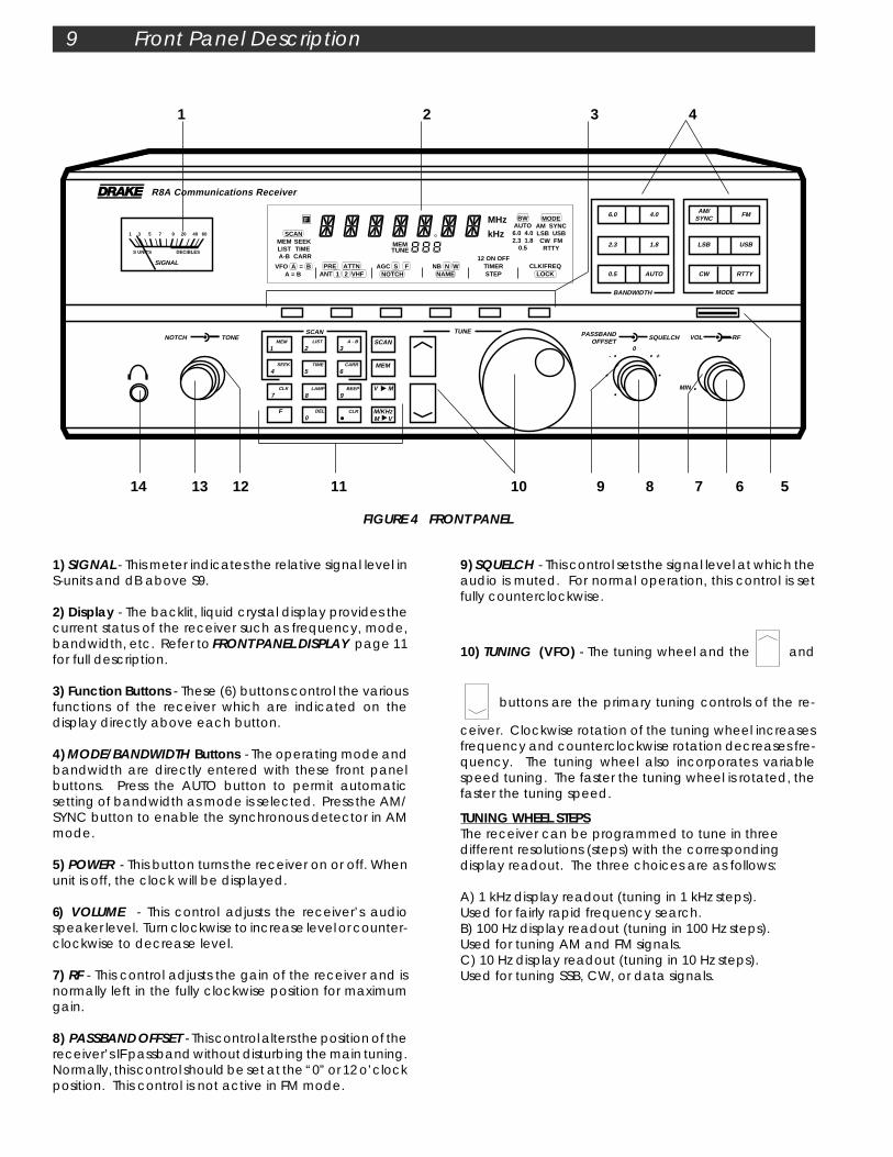
9) SQUELCH - This control sets the signal level at which theaudio is muted. For normal operation, this control is setfully counterclockwise.
10) TUNING (VFO) - The tuning wheel and the and
buttons are the primary tuning controls of the re-
ceiver. Clockwise rotation of the tuning wheel increasesfrequency and counterclockwise rotation decreases fre-quency. The tuning wheel also incorporates variablespeed tuning. The faster the tuning wheel is rotated, thefaster the tuning speed.
1) SIGNAL - This meter indicates the relative signal level inS-units and dB above S9.
2) Display - The backlit, liquid crystal display provides thecurrent status of the receiver such as frequency, mode,bandwidth, etc. Refer to FRONT PANEL DISPLAY page 11for full description.
3) Function Buttons - These (6) buttons control the variousfunctions of the receiver which are indicated on thedisplay directly above each button.
4) MODE/BANDWIDTH Buttons - The operating mode andbandwidth are directly entered with these front panelbuttons. Press the AUTO button to permit automaticsetting of bandwidth as mode is selected. Press the AM/SYNC button to enable the synchronous detector in AMmode.
5) POWER - This button turns the receiver on or off. Whenunit is off, the clock will be displayed.
6) VOLUME - This control adjusts the receiver’s audiospeaker level. Turn clockwise to increase level or counter-clockwise to decrease level.
7) RF - This control adjusts the gain of the receiver and isnormally left in the fully clockwise position for maximumgain.
8) PASSBAND OFFSET - This control alters the position of thereceiver’s IF passband without disturbing the main tuning.Normally, this control should be set at the “0” or 12 o’clockposition. This control is not active in FM mode.
FIGURE 4 FRONT PANEL
1 2 3 4
9 Front Panel Description
14 13 12 11 10 9 8 7 6 5
TUNING WHEEL STEPSThe receiver can be programmed to tune in threedifferent resolutions (steps) with the correspondingdisplay readout. The three choices are as follows:
A) 1 kHz display readout (tuning in 1 kHz steps).Used for fairly rapid frequency search.B) 100 Hz display readout (tuning in 100 Hz steps).Used for tuning AM and FM signals.C) 10 Hz display readout (tuning in 10 Hz steps).Used for tuning SSB, CW, or data signals.

Front Panel Description cont'd 10
ModeLSB, USB, RTTY, CW
AM, FM
Tuning andDisplay Resolution (Hz)
10100
Table 1
The step size may be programmed per mode. The re-ceiver, as shipped from the factory, has step sizes pro-grammed as shown in Table 1 below:
To reset the receiver to the factory settings for STEP size,AGC setting, BANDWIDTH, etc.:Press the POWER button to turn the receiver off. Press the
CLR button and hold while pressing the POWER button toturn Power on. After three seconds, the receiver will reset.
The tuning wheel incorporates variable rate tuning. Thefaster the tuning wheel is rotated, the greater the fre-quency change per tuning wheel revolution.
BUTTON STEPS
The button increases and the button de-
creases the frequency by fixed steps with each depres-sion as programmed. Pressing and holding either buttonwill allow continuous stepping up or down as long as thebutton is depressed. The fixed steps are as follows:
To tune in 100 kHz steps, press the F button. With the
F displayed, press the / buttons, as desired,
to tune in 100 kHz increments.
Note that, regardless of the / button step
increments, the display always indicates the programmedtuning resolution (step) available by using the tuningwheel at any frequency.
11) Program Buttons -SCAN (Scan) - Pressing this button starts a scan as definedby the scan indicators ( ) on the display.
Please refer to SCAN FUNCTIONS on pages 22-23 fordetails.
MEM (Memory) - Pressing this button in VFO mode switchesthe receiver to memory mode. Please refer to MEMORYFUNCTIONS on pages 20-21 for details.
V M (VFO to Memory) - Pressing this button in VFO modetransfers the current status of the receiver, for example,frequency, mode, bandwidth, etc., into memory. Pleaserefer to MEMORY FUNCTIONS on pages 20-21 for details.
M VM/KHz (MHz or kHz Frequency Readout or Memory to VFO)
- Pressing the F button followed by the M VM/KHz button,
changes the frequency readout to MHz or kHz as desired.Pressing this button in memory mode transfers the con-tents of the current memory location, i.e., frequency,mode, bandwidth, etc. to the selected VFO. Refer toMEMORY FUNCTIONS on pages 20-21 for details.
F (Function) - Pressing this button accesses secondaryfunctions, printed in orange, on the numeric buttons 0-9and switches the function line on the display above the 6function buttons.
DEL
0 to BEEP
9 - These buttons are normally used for directnumeric entries in VFO, memory, clock, and timer modes.Each button also has a secondary function printed inorange. These secondary functions are used as follows:Press F , MEM
1 to CARR
6 for programming scan methods.Refer to SCAN FUNCTIONS pages 22-23.Press F , CLK
7 to access the clock. Refer to CLOCK &TIMER FUNCTIONS page 25-26.Press F , LAMP
8 to adjust display and signal meter back-light intensity.
Press F , BEEP
9 to turn audible beep on or off. Refer to BEEPTONES page 15.Press F , DEL
0 to delete a program from a memorylocation. Refer to DELETING A MEMORY LOCATION page21.
CLR (Decimal) - This button is used when entering afrequency directly with the numeric buttons. Also used inconjunction with the F button to provide a Clear entryfunction. Refer to DIRECT FREQUENCY ENTRY page 16.
12) TONE - This control is used to modify the tonal qualityof the audio. Counterclockwise rotation increases bassresponse. Flat response occurs at the 12 o'clock setting.
13) NOTCH - This control is used to “tune” the notchfrequency and is active when
AGC S FNOTCH is displayed. This
control is not active in FM mode.
14) Headphone - This connector accepts a standard1/4" diameter 2-circuit (monaural) or 3-circuit (stereo)phone plug. Audio is monaural in either case. All speakeroutputs are automatically switched off when using head-phones.
FrequencyRange
100-540 kHz540-1800 kHz
1800-30,000 kHz
Step5 kHz
10 kHz (9 kHz ifprogrammed)
5 kHz
SCANMEM LIST A-B
SEEK TIME CARR
BW AUTO 6.0 4.0 2.3 1.8
0.5
MODE AM SYNC LSB USB CW FM RTTY
SCANMEM LIST A-B
SEEK TIME CARR
MEM TUNE
VFO A = B A = B
PRE ATTN ANT 1 2 VHF
AGC S F NOTCH
NB N W NAME
12 ON OFF
TIMER STEP
CLK/FREQ LOCK
F
kHz
MHz
11 Front Panel Display
8 FIGURE 5 FRONT PANEL DISPLAY
315
4
6
7
9 11 210 13 12 15 14
17
16
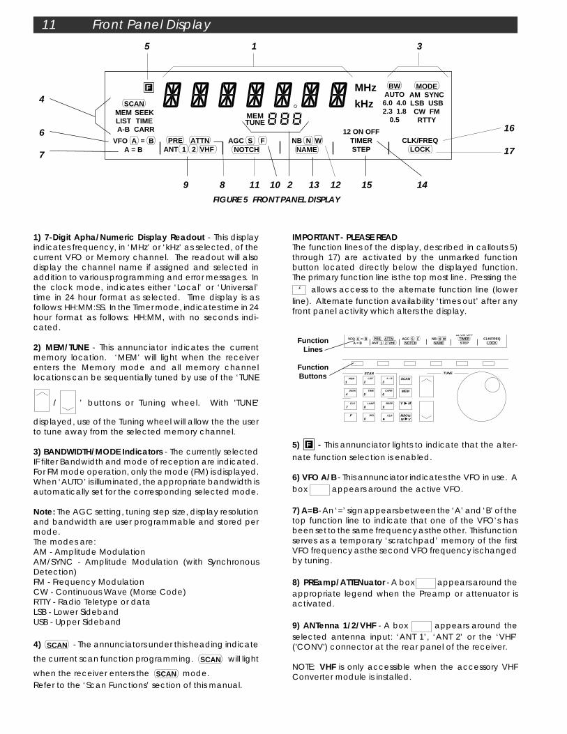
IMPORTANT - PLEASE READThe function lines of the display, described in callouts 5)through 17) are activated by the unmarked functionbutton located directly below the displayed function.The primary function line is the top most line. Pressing the
F allows access to the alternate function line (lowerline). Alternate function availability ‘times out’ after anyfront panel activity which alters the display.
5) F - This annunciator lights to indicate that the alter-
nate function selection is enabled.
6) VFO A/B - This annunciator indicates the VFO in use. Abox appears around the active VFO.
7) A=B - An ‘=’ sign appears between the ‘A’ and ‘B’ of thetop function line to indicate that one of the VFO’s hasbeen set to the same frequency as the other. This functionserves as a temporary ‘scratchpad’ memory of the firstVFO frequency as the second VFO frequency is changedby tuning.
8) PREamp/ATTENuator - A box appears around theappropriate legend when the Preamp or attenuator isactivated.
9) ANTenna 1/2/VHF - A box appears around theselected antenna input: ‘ANT 1’, ‘ANT 2’ or the ‘VHF’('CONV') connector at the rear panel of the receiver.
NOTE: VHF is only accessible when the accessory VHFConverter module is installed.
1) 7-Digit Apha/Numeric Display Readout - This displayindicates frequency, in ‘MHz’ or ‘kHz’ as selected, of thecurrent VFO or Memory channel. The readout will alsodisplay the channel name if assigned and selected inaddition to various programming and error messages. Inthe clock mode, indicates either ‘Local’ or ‘Universal’time in 24 hour format as selected. Time display is asfollows: HH:MM:SS. In the Timer mode, indicates time in 24hour format as follows: HH:MM, with no seconds indi-cated.
2) MEM/TUNE - This annunciator indicates the currentmemory location. ‘MEM’ will light when the receiverenters the Memory mode and all memory channellocations can be sequentially tuned by use of the ‘TUNE
/ ’ buttons or Tuning wheel. With 'TUNE'
displayed, use of the Tuning wheel will allow the the userto tune away from the selected memory channel.
3) BANDWIDTH/MODE Indicators - The currently selectedIF filter Bandwidth and mode of reception are indicated.For FM mode operation, only the mode (FM) is displayed.When ‘AUTO’ is illuminated, the appropriate bandwidth isautomatically set for the corresponding selected mode.
Note: The AGC setting, tuning step size, display resolutionand bandwidth are user programmable and stored permode.The modes are:AM - Amplitude ModulationAM/SYNC - Amplitude Modulation (with SynchronousDetection)FM - Frequency ModulationCW - Continuous Wave (Morse Code)RTTY - Radio Teletype or dataLSB - Lower SidebandUSB - Upper Sideband
4) SCANMEM SEE
- The annunciators under this heading indicate
the current scan function programming. SCANMEM SEE
will light
when the receiver enters the SCANMEM SEE
mode.Refer to the ‘Scan Functions’ section of this manual.
FunctionLines
FunctionButtons
TUNESCAN
SCAN
MEM
LIST
2 A - B
3
SEEK
4 TIME
5CARR
6
CLK
7LAMP
8BEEP
9
F DEL
0
V M
M V
A-B CARR
VFO A = B A = B
PRE ATTN ANT 1 2 VHF
AGC S F NOTCH
NB N W NAME
12 ON OFF
TIMER STEP
CLK/FREQ LOCK
M/KHz
MEM
1
CLR
Front Panel Display, cont'd. 12
10) AGC S/F - A box appears around the selectedAGC setting. With no box illuminated, the AGC is Off. Asthe receiver is factory supplied, two choices are possible:S or F. Select either the Slow or Fast AGC setting for mostall modes of operation. However, to add the 'Off' condi-tion as a third selection: Press and hold the AGC functionline button for three seconds. The choices for AGC settingwill now be among three possible conditions: ,or no box displayed (AGC Off).AGC is not displayed when the FM mode is selected.
11) NOTCH - A box appears around this annunciatorto indicate that the variable frequency audio notchcontrol is active.
12) Noise Blanker Narrow/Wide - A box appearsaround the selected noise blanking range, either Narrowor Wide. No box indicates that the noise blanker is notactivated.
13) NAME - Whenever a box appears around thisannunciator, the receiver will display channel names ifthe tuned frequency is within ± 1kHz of a stored memorychannel frequency with a name assigned. It is importantto note that, if a name is not assigned to a memorychannel, only the frequency will be displayed for thatchannel when it is recalled even though isilluminated.When the frequency first enters the 1kHz window, thename will be displayed. It will remain until the frequencyis tuned out of the window. If tuning is stopped inside thewindow (such as when the listener is interested in thesignal) name display is reversed; when tuning resumes,the name will be replaced by the frequency to allow finetuning of the tuned signal. The frequency will remain onthe display until tuning is stopped for 2 seconds, then thename will return.If, while fine tuning, the frequency goes outside the win-dow, the display will revert to the original name and will bedisplayed as soon as the frequency enters the window.
14) TIMER - The number 1 or 2 will light to indicate whichtimer is selected. If one or both timers (Timer 1 and/orTimer 2) is/are enabled, the 1 and/or 2 annunciator(s) willcontinue to be displayed after the receiver is turned off.The ON and OFF annunciators are displayed to indicatewhich respective time is being programmed.
15) STEP - When selected, permits setting of three differentstep sizes and corresponding display resolutions. Refer to‘FREQUENCY STEP SELECTION’ on page 16.
16) CLOCK/FREQUENCY - Either the Time or Frequencycan be displayed by pressing the function button belowthis annunciator.
17) LOCK - A box appears around this annunciatorto indicate that all front panel buttons and Tuning wheelentries are locked out.
F H
S OTCH
NB N WNAME

A N T 2CONV ANT 1
50 50
50 GND 500
EXT 11 - 16 VDC IN
- +
108- 132V 90-
110V
216- 264V
180-
22
0V
W A R N I N G RISK OF ELECTRIC
SHOCK DO NOT OPEN
RISQUE DE CHOC ELECTRIQUE NE PAS OUVRIRAVIS
CAUTION: - RISK OF FIRE - REPLACE FUSE AS MARKED AFTER DISCONNECTING UNIT FROM AC LINE.
ATTENTION: - RISQUE D'INCENDIE - REMPLACEZ FUSIBLE DU TYPE INDIQUÉ APRÉS DEBRANCHER DU SECTEUR.
INT EXT
BOTH
EXT OUT OUT MUTE
SPEAKER LINE AUDIO
INTERFACE
RS - 232C
DC
ACDISCONNECT FROM SUPPLY BEFORE
CHANGING RANGES
WARNING40 WATTS 50/60 Hz
100VAC 400 mA 120VAC 400 mA 200VAC 200 mA 240VAC 200 mA TYPE T
GND
TIMER
MADE IN U. S. A. BY ®
4
2A TYPE T
13 Rear Panel Description
15 14 13 12 11 10 9
1 2 3 4 5 6 7 8
1) CONV - This connector is the antenna input to theoptional VHF Converter. Attach a 50 OHMS nominalimpedance coaxial feed line from the antenna. Thisconnector accepts a standard PL-259 plug.
2) ANT 1 - This connector is used when attaching receivingantennas with coaxial feed lines of 50 OHMS nominalimpedance. Accepts a standard PL-259 plug.
3) ANT 2 - This connector can be used to attach either alow impedance (50 OHMS nominal) or high impedance(500 Ohm nominal) antenna. The center clip is groundand its connection should be as short as possible.
4) EXT 11-16 VDC IN - This connector is used for poweringthe receiver from an external DC source such as a carbattery. Observe proper polarity when attaching wires.This connector is internally protected from reverse polar-ity.
5) DC Fuse - This is a 2 ampere type T fuse. Replace withsame type and rating.
6) AC LINE Voltage Selector - This switch is used to selectthe proper line voltage setting for your particular area. BECERTAIN OF THE OPERATING VOLTAGE BEFORE CONNECT-ING THIS RECEIVER TO THE MAINS SOURCE. Also, theproper mains fuse and line cord may need to be installed.See items (7) and (8).
7) Fuse - Check for proper fusing prior to connecting thisreceiver to the mains source (see page 4). Fuse is 5x20 mmSLO-BLO®, T400 mA for nominal 115/127 VAC operation;T200 mA, 250V for nominal 220/240 VAC operation.
8) Power Line Cord Receptacle - This receptacle acceptsa three-wire power cable. When the cable is connectedto an appropriate power line outlet, the instrument isgrounded.
This unit is shipped with a cord intended for nominal 115/127 VAC mains supply. For operation of this unit onnominal 220/240 VAC mains supply, use the proper cableassembly approved by your local codes.
9) GND (Ground) - The earth ground wire connected hereshould be as short as possible.
10) TIMER - This 5 pin din connector provides switchingcontacts for on/off control of an external device such asa cassette tape recorder. Refer to CLOCK & TIMER FUNC-TIONS page 25.
11) MUTE - The RCA connector provides a method ofmuting the receiver for use with a transmitter. Groundcenter pin to mute.
12) Interface RS-232C - This 9 pin DB-9 connector providesa standard RS-232C interface to a keyboard terminal.Refer to RS-232C INTERFACE page 30.
13) LINE AUDIO OUT - Both RCA connectors provide aconstant low level audio source independent of thesetting of the volume control. They are designed tointerface to tape recorders, CW/RTTY demodulators,amplifiers, etc.
14) EXT (External Speaker) - This connector accepts astandard 1/4" diameter, 2-circuit, (monaural) phone plugfor connection of a 4-8 ohm external speaker.
15) Speaker Switch (INT/BOTH/EXT) - This 3 position switchallows selection of internal only, both internal and exter-nal, or external only speaker outputs.
FIGURE 6 REAR PANEL

MUTE OPERATION OF THE R8A COMMUNICATIONS RECEIVER
The mute line does not disconnect the antenna. OlderDrake equipment required the mute line to be groundedfor receive. This receiver requires ground to mute.When using the receiver with older Drake equipment,an external relay is recommended to operate themute line. Sometimes this may be accomplished byusing a spare set of relay contacts on the antennaswitch-over relay.
If you are not operating a linear amplifier, you can usethe vox relay contacts to provide control of the re-ceiver muting. Simply connect the two pin jack or RCAphono socket of the AC-4, PS-75, PS-7, power supply tothe mute jack on the R8A.
When using this receiver with an external transmitter, itis often desirable to be able to externally mute thereceiver during transmission. The receiver provides thisexternal control by use of the "MUTE" connectorlocated on the rear panel. Grounding the center pinof this connector forces the AGC circuitry to shut downall RF/IF stages, thus quieting or muting the receiver.
Mute Operation of the Receiver 14
ANTENNA COAX
ANTENNA RELAY CONTROL ANTENNA RELAYe.g. DOW-KEY,
ETC.
R8A RECEIVERANTENNA COAXTRANSMITTER
OR
MUTE CABLE
FIGURE 7 SUGGESTED HOOKUP FOR MUTE OPERATION

BW AUTO 6.0 4.0 2.3 1.8
0.5
MODE AM SYNC LSB USB CW FM RTTY
SCANMEM LIST A-B
SEEK TIME CARR
MEM TUNE
VFO A = B A = B
PRE ATTN ANT 1 2 VHF
AGC S F NOTCH
NB N W NAME
12 ON OFF
TIMER STEP
CLK/FREQ LOCK
F
TUNESCANNOTCH TONE
SCAN
MEM
6.0 4.0 AM/ SYNC
FM
2.3 1.8 LSB USB
0.5 AUTO CW RTTY
BANDWIDTH MODE
LIST
2 A - B
3
SEEK
4 TIME
5CARR
6
CLK
7LAMP
8BEEP
9
F DEL
0
V M
M V
SQUELCHPASSBAND OFFSET
VOL RF
MIN
0 - +
R8A Communications Receiver
1 3 5 7 9 20 40 60
S UNITS DECIBLES
SIGNAL
M/KHz
MEM
1
CLR
kHz
MHz
15 Getting Started
TONECENTERED
NOTCHCENTERED
VOLUMECOUNTER-CLOCKWISE
FIGURE 8
SQUELCHCOUNTER-CLOCKWISE
PASSBAND OFFSETCENTERED
RF GAINCLOCKWISE
GENERAL OPERATING INFORMATIONThis receiver is easy to use. Please take a few moments toread through this section and familarize yourself withgeneral operating information.
MICROPROCESSOR RESETA power-up reset is activated each time the unit isconnected to an AC or DC power source. This may beconfirmed by the front panel display illuminating allannunciators for 3 seconds, followed by the clock display.If, for any reason, the receiver display or operationbecomes confused or a ‘PWRFAIL’ message is displayed,unplug the receiver from the power source andreconnect. Normal operations of the receiver are haltedin the ‘PWRFAIL’ mode. Note: Any programmed memorylocations will NOT be lost under a power-up reset or undera ‘PWRFAIL’ mode due to the memory design of thereceiver.
BEEP TONESThe receiver responds to all button depressions with anaudible beep. They are as follows:
1 short tone for any button depression.1 long, high tone when programming in memory mode.1 long, low tone for any illegal button depression.
GETTING STARTED1. Please refer to FIGURE 8 and adjust controls as shown.2. Press the (power) button.3. Press VFO button to select VFO A.4. Press F button followed by the ANT button to selectdesired antenna input.5. Press one of the MODE buttons to select the desiredmode of reception. Press the AUTO (bandwidth) buttonfor automatic bandwidth selection with mode change orpress one of the BANDWIDTH buttons to select the desiredIF Bandwidth.
AUTO MODE, and the Default BANDWIDTH/STEP/AGC Set-tings
If the AUTO mode is selected, the default Bandwidth, Stepand AGC setting are automatically recalled when themode is changed. These defaults are user program-mable. To set the default, turn AUTO off (press the AUTObutton until AUTO is extinguished in the display area). Setthe Bandwidth, Step and AGC as desired for the defaults.Press and hold the corresponding MODE button for whichthe defaults are being set. A memory beep will indicatethat the defaults have been stored. Repeat the aboveprocedure for all modes that are to be programmed.Once the defaults are programmed, and the AUTO modeis selected, changing modes will recall the user pro-grammed BANDWIDTH, STEP and AGC settings.
6. Check that 'SPEAKER' switch on rear panel is on desiredsetting.7. Adjust VOLUME (VOL) control for desired level.Adjust SQUELCH control fully counterclockwise. Adjust RFGAIN control fully clockwise.Press the F button followed by
M VM/KHz to set frequency
entry units.8. Press the CLK/FREQ button as required, to displayfrequency. Use the numeric keypad to enter frequency,
in MHz or kHz, as indicated, directly or use the or
tuning buttons to rapidly tune near a frequency, then finetune with the tuning knob.
FREQUENCY STEP SELECTIONTUNING WHEEL STEPSThe receiver can be programmed to tune in three differ-ent resolutions (steps) with the corresponding displayreadout.

The three choices are as follows: A) 1 kHz display readout (tuning in 1 kHz steps).Used for fairly rapid frequency search. B) 100 Hz display readout (tuning in 100 Hz steps).Used for tuning AM and FM signals. C) 10 Hz display readout (tuning in 10 Hz steps).Used for tuning SSB, CW, or data signals.
The step size may be programmed per mode. The re-ceiver, as shipped from the factory, has step sizes pro-grammed as shown in Table 2 below:
To change the step, press the F button followed by theSTEP function line button.To reset the receiver to the factory settings for STEP size,AGC setting, BANDWIDTH, etc.:Press the POWER button to turn the receiver off. Press the
CLR button and hold while pressing the POWER button toturn Power on. After three seconds, the receiver will reset.The tuning wheel incorporates variable rate tuning. Thefaster the tuning wheel is rotated, the greater the fre-quency change per tuning wheel revolution.
BUTTON STEPS
The button increases and the button de-
creases the frequency by fixed steps with each depres-sion as programmed. Pressing and holding either buttonwill allow continuous stepping up or down as long as thebutton is depressed. The fixed steps are as follows:
To tune in 100 kHz steps, press the F button. With the
F displayed, press the / buttons, as desired,
to tune in 100 kHz increments. Note that, regardless of the
/ button step increments, the display always
indicates the programmed tuning resolution (step) avail-able by using the tuning wheel at any frequency.
Getting Started cont,d. 16
For example, suppose you want WWV at 10 MHz in VFO Bwhile using VFO A to tune other frequencies.Press: VFO to select BPress: AM mode buttonPress: MEM
1 DEL
0 CLR CLR - WWV is now stored in VFO B.Press: VFO to select ATune other frequencies with VFO A. To recall WWV, pressVFO function button. NOTE: See 'DIRECT FREQUENCY EN-TRY' section below for explanation of second CLR entry.B) A=BThis function is used to transfer the frequency of the activeVFO into the inactive VFO. This is handy if you are tuningand would like to temporarily hold a certain frequency asyou continue tuning. For example, suppose you aretuning in VFO B and come across a station at 4.5 MHz youwould like to occasionally check.Press: F , then A=B. Equal (=) symbol now appearsbetween VFO A = B.Continue tuning and recall station at 4.5 MHz anytime bypressing the VFO button.
DIRECT FREQUENCY ENTRYDirect keyboard entry of a frequency is possible usingnumeric buttons 0-9 and decimal CLR allowing for rapid
frequency change. Pressing the button sequence F , CLR will cancel any frequency or memory channel num-
ber entry in progress and return the setting to its previousstate.NOTE: With the optional VHF Converter installed, enteringa three digit frequency (in MHz) is possible after firstselecting antenna.Press: VFO to select VFO A or VFO B
TO ENTER FREQUENCY IN MHz:Press: F ,
M VM/KHz to select 'MHz' display mode if required.
Enter frequency in MHz beginning with the most signifi-cant digit. You do not need to enter leading or trailingzeros.Examples:1) 1.410 MHz - Press: MEM
1 CLR SEEK
4 MEM
1 CLR
2) 29.660 MHz - Press: SCAN
LIST
2 BEEP
9 CLR CARR
6 CARR
6 CLR
The second depression of the decimal CLR button acts asan 'Enter' and causes immediate response to the entereddigits. If you forget to press the decimal CLR button asecond time, the receiver will automatically do so for you,but with a slight delay.3) 700 KHz (= .70 MHz) - Press: CLR CLK
7 . After 3 second
pause, frequency will be entered.
TO ENTER FREQUENCY IN kHz:Press: F ,
M VM/KHz to select 'kHz' display mode if not already
selected. Enter frequency in kHz beginning with the mostsignificant digit, followed by a double depression of the
CLR button. Example:
1) 700 kHz - Press: CLK
7 DEL
0 DEL
0 CLR CLR
Frequency will be immediately displayed. Attempting toenter a frequency outside of the tuning range of thereceiver will cause the word ERROR to be displayed alongwith the error beep to be heard. The receiver will thenreturn to the last displayed frequency.
ModeLSB, USB, RTTY, CW
AM, FM
Tuning andDisplay Resolution (Hz)
10100
Table 2
DUAL VFO'sA) VFO A/VFO BTwo VFOs (A and B) are provided on the receiver. Selec-tion is made with the VFO function key. Each VFO can beset to any frequency and act as a temporary memorylocation.
FrequencyRange
100-540 kHz540-1800 kHz
1800-30,000 kHz
Step5 kHz
10 kHz* (9 kHz ifprogrammed)
5 kHz
N VHF
17 Getting Started cont'd.
AM SYNCHRONOUS DETECTOR OPERATIONFor general tuning and listening, the normal AM detectoris best. It allows normal AM reception while providing thecapability to offset the IF passband without causing distor-tion. If the received signal is experiencing severe fading asis common on many SW and BC bands, the synchronousdetector should be engaged. Make sure the main tuningis set to within 1 kHz of the station’s transmitting frequency.Adjust the PASSBAND OFFSET control and change band-width as required to minimize any interference. Press AM/SYNC to activate the synchronous detector. The wordSYNC is diplayed following AM to indicate the synchro-nous detector is selected and locked. SYNC will flash toindicate that the detector is acquiring lock. This detectorprovides a very powerful aid in reducing the severe audiodistortion that can occur during the time period when thecarrier of the received AM signal is cancelled or reducedby propagation effects.When the synchronous detector has been activated,moving the main tuning over ±200 Hz will automaticallyswitch the receiver out of synchronous detection whilethe synchronous detector re-aquires lock. The ‘SYNC’annunciator will flash briefly until lock is achieved. Also,moving the PASSBAND OFFSET control while the synchro-nous detector is engaged, will cause the receiver tomomentarily switch out of synchronous detection whilethe synchronous detector re-aquires lock. The ‘SYNC’annunciator will flash briefly until lock is achieved.
FRONT PANEL LOCK (UNLOCK)First be sure the receiver is in the VFO mode, ( MEM orSCAN not displayed). All button entries, display settingsand the large tuning knob can be locked if desired.Press F LOCK to lock front panel. All analog controlknob functions, except tuning, will still remain operable.Press F LOCK to unlock front panel if previously locked.
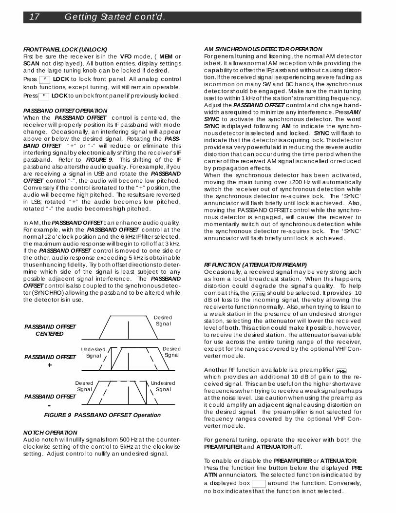
PASSBAND OFFSET OPERATIONWhen the PASSBAND OFFSET control is centered, thereceiver will properly position its IF passband with modechange. Occasionally, an interfering signal will appearabove or below the desired signal. Rotating the PASS-BAND OFFSET “+” or “-” will reduce or eliminate thisinterfering signal by electronically shifting the receiver’s IFpassband. Refer to FIGURE 9. This shifting of the IFpassband also alters the audio quality. For example, if youare receiving a signal in USB and rotate the PASSBANDOFFSET control “-”, the audio will become low pitched.Conversely if the control is rotated to the “+” position, theaudio will become high pitched. The results are reversedin LSB; rotated “+” the audio becomes low pitched,rotated “-” the audio becomes high pitched.
In AM, the PASSBAND OFFSET can enhance audio quality.For example, with the PASSBAND OFFSET control at thenormal 12 o’clock position and the 6 kHz IF filter selected,the maximum audio response will begin to roll off at 3 kHz.If the PASSBAND OFFSET control is moved to one side orthe other, audio response exceeding 5 kHz is obtainablethus enhancing fidelity. Try both offset directions to deter-mine which side of the signal is least subject to anypossible adjacent signal interference. The PASSBANDOFFSET control is also coupled to the synchronous detec-tor (SYNCHRO) allowing the passband to be altered whilethe detector is in use.
NOTCH OPERATIONAudio notch will nullify signals from 500 Hz at the counter-clockwise setting of the control to 5kHz at the clockwisesetting. Adjust control to nullify an undesired signal.
DesiredSignalPASSBAND OFFSET
CENTERED
DesiredSignal
UndesiredSignalPASSBAND OFFSET
+
UndesiredSignal
PASSBAND OFFSET
-FIGURE 9 PASSBAND OFFSET Operation
DesiredSignal
RF FUNCTION (ATTENUATOR/PREAMP)Occasionally, a received signal may be very strong suchas from a local broadcast station. When this happens,distortion could degrade the signal’s quality. To helpcombat this, the ATTN should be selected. It provides 10dB of loss to the incoming signal, thereby allowing thereceiver to function normally. Also, when trying to listen toa weak station in the presence of an undesired strongerstation, selecting the attenuator will lower the receivedlevel of both. This action could make it possible, however,to receive the desired station. The attenuator is availablefor use across the entire tuning range of the receiver,except for the ranges covered by the optional VHF Con-verter module.
Another RF function available is a preamplifier PRE which provides an additional 10 dB of gain to the re-ceived signal. This can be useful on the higher shortwavefrequencies when trying to receive a weak signal perhapsat the noise level. Use caution when using the preamp asit could amplify an adjacent signal causing distortion onthe desired signal. The preamplifier is not selected forfrequency ranges covered by the optional VHF Con-verter module.
For general tuning, operate the receiver with both thePREAMPLIFIER and ATTENUATOR off.
To enable or disable the PREAMPLIFIER or ATTENUATOR:Press the function line button below the displayed PREATTN annunciators. The selected function is indicated bya displayed box around the function. Conversely,no box indicates that the function is not selected.
RLIST A-B
TIME CARR
TUNE
VFO A = B A = B
PRE ATTN ANT 1 2 VHF
AGC S F NOTCH
NB N W NAME
12 ON OFF
TIMER STEP
CLK/FREQ LOCK
TUNESCANNOTCH TONE
SCAN
MEM
0.5 AUTO CW RTTY
BANDWIDTH MODE
LIST
2 A - B
3
SEEK
4 TIME
5CARR
6
CLK
7LAMP
8BEEP
9
F DEL
0
V M
M V
SQUELCHPASSBAND OFFSET
VOL RF
MIN
0 - +
S UNITS DECIBLES
SIGNAL
M/KHz
MEM
1
CLR
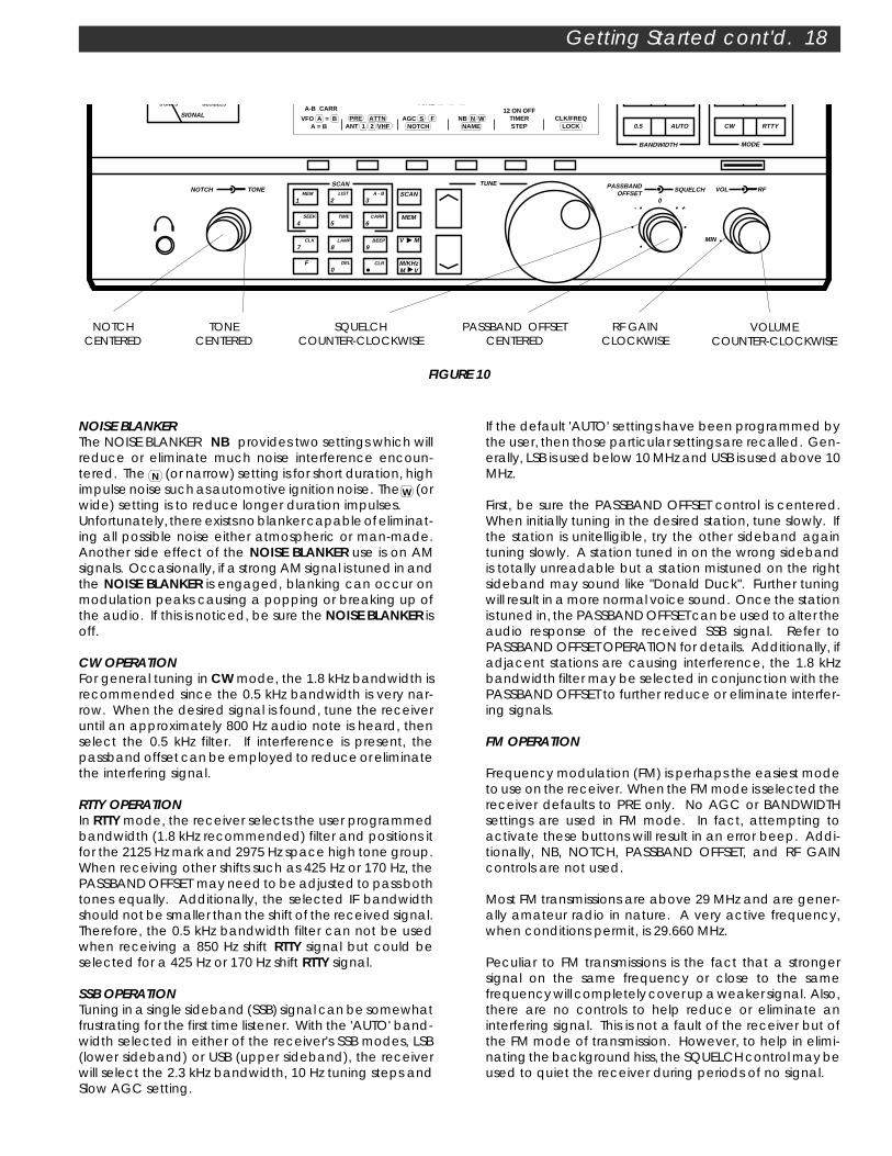
Getting Started cont'd. 18
TONECENTERED
NOTCHCENTERED
VOLUMECOUNTER-CLOCKWISE
SQUELCHCOUNTER-CLOCKWISE
PASSBAND OFFSETCENTERED
RF GAINCLOCKWISE
FIGURE 10
If the default 'AUTO' settings have been programmed bythe user, then those particular settings are recalled. Gen-erally, LSB is used below 10 MHz and USB is used above 10MHz.
First, be sure the PASSBAND OFFSET control is centered.When initially tuning in the desired station, tune slowly. Ifthe station is unitelligible, try the other sideband againtuning slowly. A station tuned in on the wrong sidebandis totally unreadable but a station mistuned on the rightsideband may sound like "Donald Duck". Further tuningwill result in a more normal voice sound. Once the stationis tuned in, the PASSBAND OFFSET can be used to alter theaudio response of the received SSB signal. Refer toPASSBAND OFFSET OPERATION for details. Additionally, ifadjacent stations are causing interference, the 1.8 kHzbandwidth filter may be selected in conjunction with thePASSBAND OFFSET to further reduce or eliminate interfer-ing signals.
FM OPERATION
Frequency modulation (FM) is perhaps the easiest modeto use on the receiver. When the FM mode is selected thereceiver defaults to PRE only. No AGC or BANDWIDTHsettings are used in FM mode. In fact, attempting toactivate these buttons will result in an error beep. Addi-tionally, NB, NOTCH, PASSBAND OFFSET, and RF GAINcontrols are not used.
Most FM transmissions are above 29 MHz and are gener-ally amateur radio in nature. A very active frequency,when conditions permit, is 29.660 MHz.
Peculiar to FM transmissions is the fact that a strongersignal on the same frequency or close to the samefrequency will completely cover up a weaker signal. Also,there are no controls to help reduce or eliminate aninterfering signal. This is not a fault of the receiver but ofthe FM mode of transmission. However, to help in elimi-nating the background hiss, the SQUELCH control may beused to quiet the receiver during periods of no signal.
NOISE BLANKERThe NOISE BLANKER NB provides two settings which willreduce or eliminate much noise interference encoun-tered. The N
ME (or narrow) setting is for short duration, high
impulse noise such as automotive ignition noise. The W E
(orwide) setting is to reduce longer duration impulses.Unfortunately, there exists no blanker capable of eliminat-ing all possible noise either atmospheric or man-made.Another side effect of the NOISE BLANKER use is on AMsignals. Occasionally, if a strong AM signal is tuned in andthe NOISE BLANKER is engaged, blanking can occur onmodulation peaks causing a popping or breaking up ofthe audio. If this is noticed, be sure the NOISE BLANKER isoff.
CW OPERATIONFor general tuning in CW mode, the 1.8 kHz bandwidth isrecommended since the 0.5 kHz bandwidth is very nar-row. When the desired signal is found, tune the receiveruntil an approximately 800 Hz audio note is heard, thenselect the 0.5 kHz filter. If interference is present, thepassband offset can be employed to reduce or eliminatethe interfering signal.
RTTY OPERATIONIn RTTY mode, the receiver selects the user programmedbandwidth (1.8 kHz recommended) filter and positions itfor the 2125 Hz mark and 2975 Hz space high tone group.When receiving other shifts such as 425 Hz or 170 Hz, thePASSBAND OFFSET may need to be adjusted to pass bothtones equally. Additionally, the selected IF bandwidthshould not be smaller than the shift of the received signal.Therefore, the 0.5 kHz bandwidth filter can not be usedwhen receiving a 850 Hz shift RTTY signal but could beselected for a 425 Hz or 170 Hz shift RTTY signal.
SSB OPERATIONTuning in a single sideband (SSB) signal can be somewhatfrustrating for the first time listener. With the 'AUTO' band-width selected in either of the receiver's SSB modes, LSB(lower sideband) or USB (upper sideband), the receiverwill select the 2.3 kHz bandwidth, 10 Hz tuning steps andSlow AGC setting.

BW AUTO 6.0 4.0 2.3 1.8
0.5
MODE AM SYNC LSB USB CW FM RTTY
SCANMEM LIST A-B
SEEK TIME CARR
MEM TUNE
VFO A = B A = B
PRE ATTN ANT 1 2 VHF
AGC S F NOTCH
NB N W NAME
12 ON OFF
TIMER STEP
CLK/FREQ LOCK
F
TUNESCANNOTCH TONE
SCAN
MEM
6.0 4.0 AM/ SYNC
FM
2.3 1.8 LSB USB
0.5 AUTO CW RTTY
BANDWIDTH MODE
LIST
2 A - B
3
SEEK
4 TIME
5CARR
6
CLK
7LAMP
8BEEP
9
F DEL
0
V M
M V
SQUELCHPASSBAND OFFSET
VOL RF
MIN
0 - +
R8A Communications Receiver
1 3 5 7 9 20 40 60
S UNITS DECIBLES
SIGNAL
M/KHz
MEM
1
CLR
kHz
MHz
19 Getting Started cont'd.
Gain and AGC OPERATIONIn a basic sense, gain means amplification. AGC is anabbreviation for Automatic Gain Control. Thus, AGChelps tune in weak signals by conveniently amplifyingthem automatically. When a strong signal is tuned in, theAGC automatically reduces the amplification since it isnot needed. This also prevents overloading the receiverand minimizes distortion. When factory supplied, AGCcan be selected to operate S(LOW) or F(AST). The SLOWAGC setting is used for reception of slowly changing signallevels such as SSB signals. The FAST AGC setting allowsmore rapid automatic receiver gain adjustment to fastchanging signal levels such as AM signals. The user canselect an off position, if desired. To select this feature,press and hold the AGC function button until a memoryconfirmation beep is heard. The AGC button will nowpermit SLOW, FAST or OFF settings. The OFF condition isindicated by the display not showing a around S orF. To remove the OFF selection option, repeat the press-and-hold sequence. If the AGC is turned off, the receivergain must be manually set by using the RF (gain) controlknob to produce distortion free reception.
HOW AGC, RF GAIN AND THE SIGNAL METER WORK TO-GETHERThe AGC function button, RF Gain control knob and theSIGNAL METER work together in the same circuit in threebasic ways.1) Fully Automatic Gain Control -Selecting either the S(LOW) or F(AST) AGC setting and fullclockwise RF Gain setting makes the gain (amplification)control fully automatic. No other gain adjustments arerequired. Using the AGC is the most convenient way tooperate the receiver and is recommended for almost allreceiving conditions.The Signal Meter needle automatically fluctuates with the
strength of the signal received. A weak signal is indicatedby the signal meter needle moving to the left (for example- 3). A strong signal is indicated by the signal meter needlemoving to the right (for example - 40).
2) Manual Gain Control With AGC On (Slow or Fast) -The maximum gain level can be reduced manually, asdesired, by using the RF control knob. Turning the RFcontrol knob counterclockwise will reduce the gain, caus-ing the signal meter needle to move upscale. With thegain reduced manually, there will be less backgroundnoise when no signal is present, but signals stronger thanthe S-meter setting will be received normally.
3) Manual Gain Control With AGC Off -With the AGC off, the RF Gain control must be rotatedcounterclockwise until the gain is reduced to the pointwhere no signal distortion occurs. This mode of operationis seldom used.
RF control knob (gain)(CLOCKWISE and COUNTERCLOCKWISE)
AGC function button and dislpay(FAST, SLOW and OFF)
SIGNAL METER
FIGURE 11

BW AUTO 6.0 4.0 2.3 1.8
0.5
MODE AM SYNC LSB USB CW FM RTTY
SCANMEM LIST A-B
SEEK TIME CARR
MEM TUNE
VFO A = B A = B
PRE ATTN ANT 1 2 VHF
AGC S F NOTCH
NB N W NAME
12 ON OFF
TIMER STEP
CLK/FREQ LOCK
F
TUNESCANNOTCH TONE
SCAN
MEM
6.0 4.0 AM/ SYNC
FM
2.3 1.8 LSB USB
0.5 AUTO CW RTTY
BANDWIDTH MODE
LIST
2 A - B
3
SEEK
4 TIME
5CARR
6
CLK
7LAMP
8BEEP
9
F DEL
0
V M
M V
SQUELCHPASSBAND OFFSET
VOL RF
MIN
0 - +
R8A Communications Receiver
1 3 5 7 9 20 40 60
S UNITS DECIBLES
SIGNAL
M/KHz
MEM
1
CLR
kHz
MHz
Memory Functions 20
PREPROGRAMMED MEMORY CHANNELS LIST
MEMORYCHANNEL
MEM 00MEM 01MEM 02MEM 03MEM 04MEM 05MEM 06MEM 07MEM 08MEM 09MEM 10MEM 11MEM 12MEM 13MEM 14MEM 15MEM 16MEM 17MEM 18MEM 19
All above are stored as VFO A, ANT 1, PREAMPLIFIER Off,AGC S and BW as selected by the particular mode.
MEMORY FUNCTIONS
The receiver contains 440 programmable memory loca-tions that can be used to store and recall commonlymonitored frequencies. These 440 locations are dividedinto blocks of 10, ie, 00-09, 10-19, 20-29, etc. This allowsconvenient grouping of frequencies. As an example, 00-09 could be broadcast stations, 10-19 could be timestations such CHU and WWV, frequencies for listening atdifferent times of day, etc. The receiver is preprogrammed(at the factory) with (20) useful frequencies and corre-sponding mode in memory channels 00-19. With memorylocations programmed, you can use the various scanfunctions to automatically monitor desired memory fre-quencies. The following may be stored in any memorylocation:1) Frequency2) Mode3) Bandwidth4) AGC setting5) PRE or ATTN setting6) Antenna7) Notch ON/OFF8) Noise blanker setting9) Synchronous detector ON/OFF
FIGURE 12
FREQUENCY
53023003200390047505800710095001160013570151001748021450256005000100001500020000733514670
MODE
AMAMAMAMAMAMAMAMAMAMAMAMAMAMAMAMAMAMAMAM
NAME
AM BCB120M90M75M60M49M41M31M25M22M19M16M13M11M
WWVWWVWWVWWVCHUCHU

21 Memory Functions cont'd.
MEMORY LOCATION PROGRAMMING
First be sure the receiver is in the VFO mode (MEM, MEMTUNE or SCAN not displayed).A) Select the desired frequency, mode, bandwidth, etc.B) Press: V M and within three seconds, enter a three digitnumber from 000 to 439. A confirmation beep is heard.C) Receiver will switch to NAME mode. The receiver is nowready to accept a 7-digit name for this particular memorychannel as indicated by the blinking NAME annunciator.Name Assignment
BW AUTO 6.0 4.0 2.3 1.8
0.5
MODE AM SYNC LSB USB CW FM RTTY
SCANMEM LIST A-B
SEEK TIME CARR
VFO A = B A = B
PRE ATTN ANT 1 2 VHF
AGC S F NOTCH
NB N W NAME
12 ON OFF
TIMER STEP
CLK/FREQ LOCK
F
If you do not want to store a name with this memorychannel, press the V M button.To assign a name to this memory channel, turn the Tuningwheel slowly to select the desired character or blank
space at each flashing digit location. Press the
button to scroll right. Press the button to scroll left.
After entering all desired name information, press V M tostore the information and return the receiver to the VFOmode. The stored name and assigned memory channelnumber will be displayed.
RECALLING A MEMORY LOCATION
First, be sure that the receiver is in the VFO mode (MEM,MEM TUNE or SCAN
EM SEE not displayed). There are two basic
methods for selecting a memory location. The MEM TUNEmethod permits frequency tuning after recalling a memorylocation by turning the Tuning wheel. Additional pro-grammed memory locations are conveniently recalled
by pressing the or buttons or by directly entering
the three digit memory number. The MEM method, doesnot permit frequency retuning, but does permit conve-nient selection of programmed memory channels by
turning the Tuning wheel, pressing the buttons, or
by directly entering the three digit memory number.
A) MEM TUNEFirst , be sure that the receiver is in the VFO mode (MEM,MEM TUNE or SCAN
EM SEE not displayed). Press the MEM button.
MEM TUNE should be displayed. If not, press the MEM
button and hold to switch to MEM TUNE. A confirmation
beep will be heard. Press the buttons or directly
enter the desired three digit memory number.Normal VFO operation will resume and the MEM TUNEindicator will extinguish if the Tuning wheel is turned. Torecall the original memory settings, press the MEM button.
To save any altered settings, press the V M button, and
within three seconds, enter the three digit memory num-ber.
B) MEMFirst be sure that the receiver is in the VFO mode (MEM,MEM TUNE or SCAN
EM SEE not displayed). MEM should be
displayed. If not, press and hold the MEM button until aconfirmation beep is heard and the MEM annunciator isdisplayed. Select the desired memory channel by turning
the Tuning wheel, pressing the buttons, or
directly entering the three digit memory number. To
retune the frequency, press the M VM/KHz button and the
receiver will return to VFO mode. Contents of the memorylocation are not lost. Alternately, to return to the VFOmode, press the VFO function line button. The receiverreturns to the VFO mode and restores the last used fre-quency before MEM was pressed.
DELETING A MEMORY LOCATION
A) Press MEM and select desired memory location with
the buttons, or by direct entry of a three digit
memory location. If recalling an unprogrammed locationwith direct entry, an error beep is heard and Error isdisplayed.B) Press F , DEL
0 and hold until a short, high pitchedbeep is heard. Display will show a new memory channelnumber.
C) Press M VM/KHz or VFO to return to VFO mode.
ERASE ALL MEMORY CHANNELS
With power off, Press DEL
0 and hold while turning power
on. Hold DEL
0 for 3 seconds until a confirmation beep isheard and the display shows a single '-' in the MemoryNumber display.
LOCKING A MEMORY LOCATION
First be sure the receiver is in the VFO mode (MEM or SCAN
not displayed).A) Press MEM and select desired memory location with
the buttons, or by direct entry of a three digit
memory location. If recalling an unprogrammed locationwith direct entry, an error beep is heard and Error isdisplayed.
B) To lock memory location: Press F LOCK. A confirma-tion beep will be heard and MEM will now flash.
To unlock a locked memory location: Press F LOCK. Aconfirmation beep will be heard and MEM will stop flash-ing.C) Press
M VM/KHz or VFO to return to VFO mode.

BW AUTO 6.0 4.0 2.3 1.8
0.5
MODE AM SYNC LSB USB CW FM RTTY
SCANMEM LIST A-B
SEEK TIME CARR
MEM TUNE
VFO A = B A = B
PRE ATTN ANT 1 2 VHF
AGC S F NOTCH
NB N W NAME
12 ON OFF
TIMER STEP
CLK/FREQ LOCK
F
TUNESCAN
SCAN
MEM
LIST
2 A - B
3
SEEK
4 TIME
5CARR
6
CLK
7LAMP
8BEEP
9
F DEL
0
V M
M V
P
Receiver
M/KHz
MEM
1
CLR
kHz
MHz
Scan Functions 22
SCAN MEMORYTo scan all unlocked memory locations from 000 to 439:
Press: F , MEM
1 ; selects memory scan;Result: MEM lights in status area.
Select method: SEEK F , SEEK
4 or TIME F , TIME
5
or CARRIER F , CARR
6
Result: SEEK, TIME, or CARR lights in status area.Adjust squelch to quiet receiver audio.Press: SCAN ; SCAN
EM SEE flashes in status area and MEM SCAN is
displayed when the scan is activated.
Scan direction may be reversed with the buttons.
Scanning can be stopped or restarted with repeateddepressions of the SCAN button. When scan action isstopped, the receiver remains in MEMORY mode. PressVFO to return to last VFO frequency before entering the
SCAN mode or M VM/KHz to load contents of indicated memory
location into indicated VFO.
Table 3 Scan Functions
Scan AllUnlockedMemory
Locationsof User-
SelectedLists
Scan AllUnlockedMemory
Locations
FIGURE 13
METHOD
(F) (1)(F) (4)
(F) (1)(F) (5)
(F) (1)(F) (6)
Stop at First Carrier detected
Pause at Detected Carrier 5Seconds Then Resume SCAN.
Pause at Detected Carrier untilCarrier Drops for 5 Seconds,Then Resume SCAN.
MODE
SEEK
4
TIME
5
CARR
6
MEM
1
(F) (2)(F) (4)
(F) (2)(F) (5)
(F) (2)(F) (6)
SCAN LIST
2
Scan FromA to B
(F) (3)(F) (4)
(F) (3)(F) (5)
(F) (3)(F) (6)
A - B
3
SCAN FUNCTIONS
The receiver provides nine distinct scan functions whichare programmed with keys 1-6 on the numeric keypadand indicated in the scan status area of the display.
Keys 1-3 are considered modes.1 - MEM
1 Scans all unlocked memory locations.
2 - SCAN
LIST
2 Scans all unlocked memory locations withina user selected group or groups of channels.3 - A - B
3 Scans from frequency A to frequency B.
Keys 4-6 are considered methods.4 - SEEK
4 Stops scan at first carrier detected.
5 - TIME
5 Stops at detected carrier for five seconds,then resumes scan.6 - CARR
6 Stops at detected carrier until carrier dropsfor five seconds, then resumes scan.
A scan program therefore consists of any combination ofa mode and method. For example, scanning A to B andstopping at a detected carrier five seconds, then resum-ing would be programmed with:
F A - B
3 F TIME
5 and display would indicate
A-B and TIME
Table 3 charts the nine (9) scan functions.
Scan methods can be changed while the receiver isscanning. The STEP size can be changed while thereceiver is scanning. Press the F button followed bythe STEP function line button. The PREAMPLIFIER and/orATTENUATOR setting is unchanged from the setting priorto starting the scan, but may be changed while thereceiver is scanning. Press the F button followed bythe PREamp/ATTEN function line button. The clockdisplay can be accessed while the receiver is in thescan mode, but only after the receiver stops on astation. All other functions are locked out until scanfunctions are terminated.
Pressing the buttons during scan will reverse the
scan direction. When starting a scan, the direction isalways the same as the last time a scan was ended.

23 Scan Functions cont'd.
SCAN MEMORY LIST BLOCKThe memory locations 000 to 439 are partitioned into 44LISTS (blocks), with each block having ten memory loca-tions (total of 440 locations). See Table 4.
A) Single list scan
Press: F , SCAN
LIST
2 selects list scan;Result: LIST flashes in status area prompting list numberentry, 00 - 43. Enter desired list number. For example, to
scan 340 to 349, press A - B
3 , SEEK
4 .
BW AUTO 6.0 4.0 2.3 1.8
0.5
MODE AM SYNC LSB USB CW FM RTTY
LIST
SEEK
VFO A = B A = B
PRE ATTN ANT 1 2 VHF
AGC S F NOTCH
NB N W NAME
12 ON OFF
TIMER STEP
CLK/FREQ LOCK
F
kHz
MHz
B) Multiple LIST scan
Press: F SCAN
LIST
2 selects list scan.Result: LIST flashes in status area and the memory channelnumber will display the first list number in the current setup.At first, this will be - - -, indicating that no list has beenentered. Enter first list number as two digits, 00 through 43.
To enter another list number, press the button, fol-
lowed by the second list number. For example, to scan340 to 349, and 400 to 409,
press A - B
3 , SEEK
4 , , SEEK
4 , DEL
0 .
To review the current setup, press the button.
Attempting to scan an empty list will result in an error toneand request for a new value. To clear a single entry, press
CLR . To clear the entire list, press F , CLR .
Select method: SEEK F , SEEK
4 or TIME F , TIME
5
or CARRIER F , CARR
6
Result: SEEK, TIME, or CARR lights in status area.Adjust squelch to quiet receiver audio.
Press: SCAN ; SCANEM SEE
flashes in status area when scan isactivated, and display will indicate MEM SCAN until scan-ning detects a carrier on a scanned channel.
Pressing the , button during scan will reverse the
scan direction. Scanning can be stopped or re-startedwith repeated depressions of the SCAN button. When scanaction is stopped, the receiver remains in MEMORY mode.Press VFO to return to the last VFO frequency before
entering scan or M VM/KHz to load contents of indicated memory
location into indicated VFO.
LOCKING A MEMORY LOCATION
First be sure the receiver is in the VFO mode (MEM or SCAN
not displayed).A) Press MEM and select desired memory location with
the buttons, or by direct entry of a two digit
memory location. If recalling an unprogrammed locationwith direct entry, an error beep is heard and Error isdisplayed.B) To lock memory location: Press F LOCK. A confirma-tion beep will be heard and MEM will now flash.
To unlock a locked memory location: Press F LOCK. Aconfirmation beep will be heard and MEM will stop flash-ing.
C) Press M VM/KHz or VFO to return to VFO mode.
Table 4 Examples of Memory Location Blocks
MemoryLocation260 - 269
310 - 319
370 - 379
420 - 429
430 - 439
MemoryLocation000 - 009
050 - 059
100 - 109
150 - 159
200 - 209
ListNumber
0
5
10
15
20
ListNumber
26
31
37
42
43
Select method: SEEK F , SEEK
4 or TIME F , TIME
5
or CARRIER F , CARR
6
Result: SEEK, TIME, or CARR lights in status area.
Adjust squelch to quiet receiver audio.
Press: SCAN ; SCANEM SEE
lights in status area when scan isactivated and display will indicate MEM SCAN until scan-ning detects a carrier on a scanned channel. Uponcarrier detection, the SCAN
EM SEE will flash.
Pressing the buttons during scan will reverse the
scan direction. Scanning can be stopped or re-startedwith repeated depressions of the SCAN button. When scanaction is stopped, the receiver will be in MEMORY mode.Press VFO to return to last VFO frequency before enteringscan or
M VM/KHz to load contents of indicated memory loca-
tion into indicated VFO.

Scan Functions cont'd. 24
To program a 9 kHz step rate for overseas broadcast bandreception-
Press POWER to turn receiver offHold TIMER/STEP function buttonPress POWER to turn receiver on
9 kHz step in broadcast band is now programmed. Thissetting is saved even if power is removed from the re-ceiver. To change back to 10 kHz, repeat above steps.
SCAN A - BAn A - B scan allows continuous tuning of frequenciesbetween two programmed limits. Table 4 charts the tun-ing step size and and display resolution for all models. Ifthe selected scan range includes the AM broadcastband, the receiver automatically switches to a 10 kHz stepsize (9 kHz selectable) while in the AM broadcast bandrange.
To perform an A - B scan, press F , A - B
3 .Result: A - B flashes and the frequency display changes toshow one of the current scan frequency endpoints. Tochange this endpoint, enter a new frequency. To set the
second endpoint, press the or button. The
display now shows the other frequency endpoint. Enter anew frequency, if desired. To review the endpoints, press
the or buttons.
Select method: SEEK F SEEK
4 or TIME F TIME
5
or CARRIER F CARR
6
Result: SEEK, TIME, or CARR lights in status area.
Select desired mode, bandwidth (BW), antenna, etc.
Adjust squelch to quiet receiver audio.
Press SCAN ; SCANEM SEE
flashes in status area when scanis activated.
To adjust step rate: Press F STEP and step size willchange as per table 5.
Display will indicate scanned frequency. Scanning canbe stopped or restarted with repeated depressions of theSCAN button. When scan action is stopped, the receiver willbe in the VFO mode.
Scanning Resolution(Hz)
Display Resolution(Hz)
Mode
USB, LSB,CW, RTTY,AM, FM
AMBroadcast
Band
Default
1K
1K
Step 1
5K
10K*
Step 2
100
100
Default
1K
1K
Step 1
1K
1K
Step 2
100
100
(*or 9kHz if programmed)
Table 5 Scan Tuning Rates
Important Notes About ScanningTo avoid impaired scanning action, it is recommendednot intermix HF with VHF channels, which imposes rapidswitching on the antenna select relay.
In all scanning modes the setting of the SQUELCH controlis important for proper scanning action. Due to atmos-pheric noises alone, using a squelch control in the HFspectrum is, at best, a compromise. A more exact methodof SQUELCH setting is provided here.
First, be sure the SQUELCH control is counterclockwise.Next, adjust the RF gain control slowly counterclockwiseuntil the S METER reads the signal level desired to trip thesquelch circuit. For example, if you want only signals S-7 or stronger to break the SQUELCH, rotate the RF GAINcontrol until the S-METER is reading S-7. Next, leaving theRF GAIN control alone, advance the SQUELCH controlclockwise until the receiver audio just quiets. Finally,advance the RF GAIN fully clockwise. The receiver is nowready for accurate scanning.

BW AUTO 6.0 4.0 2.3 1.8
0.5
MODE AM SYNC LSB USB CW FM RTTY
SCANMEM LIST A-B
SEEK TIME CARR
MEM TUNE
VFO A = B A = B
PRE ATTN ANT 1 2 VHF
AGC S F NOTCH
NB N W NAME
12 ON OFF
TIMER STEP
CLK/FREQ LOCK
F
TUNESCANNOTCH TONE
SCAN
MEM
6.0 4.0 AM/ SYNC
FM
2.3 1.8 LSB USB
0.5 AUTO CW RTTY
BANDWIDTH MODE
LIST
2 A - B
3
SEEK
4 TIME
5CARR
6
CLK
7LAMP
8BEEP
9
F DEL
0
V M
M V
SQUELCHPASSBAND OFFSET
VOL RF
MIN
0 - +
R8A Communications Receiver
1 3 5 7 9 20 40 60
S UNITS DECIBLES
SIGNAL
M/KHz
MEM
1
CLR
kHz
MHz
25 Clock and Timer Functions
Example for Local Clock Set:With either frequency or time displayed, suppose it isdesired to set 13:01:00 -Press the F button, then press and hold the CLK
7
button until the colons flash rapidly.Press the following sequence of numeric buttons:
MEM
1 A - B
3 DEL
0
00:00:01 L 00:00:13 L 00:01:30 L
MEM
1 DEL
0 DEL
0
00:13:01 L 01:30:10 L 13:01:00 L
When the actual time is 13:01:00, Press the F button.The clock is now started.
TIMER OPERATIONTwo programmable event timers allow the receiver toturn ON or OFF at preset times. The timers may be usedseparately or together and may recall a currentlydisplayed frequency, memory channel or a combina-tion of both. In addition, programming only an OFFtime provides a Sleep timer; programming only an ONtime provides a Wake timer. Note that the timers, whenactivated, respond to the last displayed clock.Programming the timers is a two step process. Stepone is to set the ON and OFF times. Step two is toassign a frequency or memory channel to a timer. Thisassignment occurs when the desired timer is actuallyenabled.
SETTING TIMER ON/OFF TIMESPress and hold the TIMER function button for approxi-mately 2 seconds until the ON annunciator flashes. TheON Time will also be indicated in the frequency portionof the display (same readout format as the clock) aswell as the number 1 or 2 displayed to the left of theON annunciator. The number 1 or 2 indicates whichone of the two event timers you are programming.
TIME DISPLAYThe receiver incorporates dual time clocks allowing two24 hour clocks to be set and maintained. During loss ofAC power, clock operation is maintained for a periodof approximately 30 minutes. The two-event timerfunctions are also derived from the last displayed clock,therefore the clocks must be set first for proper TIMERoperation. TIMER Settings are maintained through apower loss.Pressing the CLK/FREQ function button will toggle thedisplay between the time of the current clock and theoperating frequency. Press the F button followed by
the CLK
7 button to toggle between the two clocks, Land U. Normally the clock accompanied by the L onthe display will be set with the local time, while thealternate clock will be set to display GMT (UTC) time.The receiver will display the selected clock when thePOWER is turned off.
SETTING THE 24 HOUR CLOCKSSelect local (L) or alternate time clock by pressing the
F button followed by the CLK
7 button.
With the F displayed, press and hold the CLK
7 buttonfor three seconds until the colons begin flashing rapidly.If the L is illuminated, you are setting the local clock.With U displayed, you are setting the alternate clock.Either clock can be set first. Time is entered in a 24 hourformat.Enter the time in ‘HH:MM:SS’, with the ‘colons’ under-stood.If an erroneous entry is made, simply enter the correcttime again. The incorrect entry will scroll off the display.Press the F button to start the clock when theactual time value agrees with the entered time.
FIGURE 14

Clock and Timer Functions cont'd. 26
Press the desired numeric buttons to enter a new ONtime. Enter the time in ‘HH:MM’ and in 24 hour format.Press the F button followed by the CLR button toremove the ‘On Time’ to use the timer as a Sleep timer.For a Wake timer, program an 'On Time' and removethe 'OFF' time.
To set the OFF time, Press the TIMER function buttonagain to display OFF time.Press the desired numeric buttons to enter a new OFFtime. Enter the time in ‘HH:MM’ and in 24 hour format.
Press the F button followed by the CLR button toremove the OFF time, if desired.
Press the TIMER function button again to enter TIMER 2ON time.
Press the TIMER function button again to enter TIMER 2OFF time.
Finally, press the TIMER function button to save thesettings and switch the display to normal readoutvalues.
Timer 1 Enabled; Timer 2 Disabled
BW AUTO 6.0 4.0 2.3 1.8
0.5
MODE AM SYNC LSB USB CW FM RTTY
SCANMEM LIST A-B
SEEK TIME CARR
MEM TUNE
VFO A = B A = B
PRE ATTN ANT 1 2 VHF
AGC S F NOTCH
NB N W NAME
1
TIMER STEP
CLK/FREQ LOCK
F
If either one or both the timer 1 or timer 2 are enabled,the 1 or 2 annunciator will continue to be displayedafter the receiver is turned off. Be certain to leave thevolume setting at the desired level. The receiver willautomatically turn on and off as programmed. If bothtimers are disabled, the timer programming in either orboth timers is retained, but no TIMER action will takeplace until one or both are enabled.
1) Example for Setting Timer ‘1’
With frequency displayed, suppose it is desired to setTimer 1 for a local ON Time: ‘16:59’ OFF Time: ‘18:01’Action:Press and hold the TIMER function button until the 1 ONannunciator flashes.
BW AUTO 6.0 4.0 2.3 1.8
0.5
MODE AM SYNC LSB USB CW FM RTTY
SCANMEM LIST A-B
SEEK TIME CARR
MEM TUNE
VFO A = B A = B
PRE ATTN ANT 1 2 VHF
AGC S F NOTCH
NB N W NAME
CLK/FREQ LOCK
F
1 ON TIMER STEP
Press the sequence: MEM
1 , CARR
6 , TIME
5 , BEEP
9
BW AUTO 6.0 4.0 2.3 1.8
0.5
MODE AM SYNC LSB USB CW FM RTTY
SCANMEM LIST A-B
SEEK TIME CARR
MEM TUNE
VFO A = B A = B
PRE ATTN ANT 1 2 VHF
AGC S F NOTCH
NB N W NAME
1 ON
TIMER STEP
CLK/FREQ LOCK
F
Press the TIMER function button.Press the sequence: MEM
1 , LAMP
8 , DEL
0 , MEM
1
BW AUTO 6.0 4.0 2.3 1.8
0.5
MODE AM SYNC LSB USB CW FM RTTY
SCANMEM LIST A-B
SEEK TIME CARR
MEM TUNE
VFO A = B A = B
PRE ATTN ANT 1 2 VHF
AGC S F NOTCH
NB N W NAME
1 OFF
TIMER STEP
CLK/FREQ LOCK
F
Press the TIMER function
BW AUTO 6.0 4.0 2.3 1.8
0.5
MODE AM SYNC LSB USB CW FM RTTY
SCANMEM LIST A-B
SEEK TIME CARR
MEM TUNE
VFO A = B A = B
PRE ATTN ANT 1 2 VHF
AGC S F NOTCH
NB N W NAME
CLK/FREQ LOCK
F
2 ON TIMER STEP
If it is desired to set 'Timer 2', use the same procedure asthat for 'Timer 1', otherwise, press the TIMER functionbutton twice to exit setting Timer operation and returnto normal frequency display.
ENABLING/DISABLING TIMER OPERATIONPress the TIMER function button. A '1' or '2' or '- - ' willbe displayed. After two seconds with no entry, thedisplay reverts back to frequency or time readout.Timer ‘1’ can be disabled/enabled by pressing thenumeric digit MEM
1 on the keypad while the timerenable display is showing.Timer 2 can be disabled/enabled by pressing the
numeric digit SCAN
LIST
2 on the keypad while the timerenable display is showing.
Prior to enabling either or both timers, consider one oftwo possible cases for each timer:eg.) - To Enable TIMER 1 —
1) '- -' is displayed: Press the MEM
1 button todisplay 1.
2) '1 -' is displayed: Press the MEM
1 button twice toagain display 1.
Setting a - for either timer DISABLES the respectivetimer.
Timers 1 and 2 Enabled
BW AUTO 6.0 4.0 2.3 1.8
0.5
MODE AM SYNC LSB USB CW FM RTTY
SCANMEM LIST A-B
SEEK TIME CARR
MEM TUNE
VFO A = B A = B
PRE ATTN ANT 1 2 VHF
AGC S F NOTCH
NB N W NAME
12
TIMER STEP
CLK/FREQ LOCK
F

27 Clock and Timer Functions cont'd.
It is important to note that the timer is enabled only whenthe timer is deliberately changed from a - to 1, or - to 2.Even if the 1 or 2 is already displayed, the timer is notenabled unless the - to 1 or 2 transition occurs.
2) Example for Setting Events on Two Different MemoryChannels:eg.) PROGRAMMING MEM 008 in Timer 1; MEM 029 in Timer 2:With frequency displayed,Press MEM followed with the numeric button sequence:
DEL
0 , DEL
0 , LAMP
8 .
Press the timer function button followed within 2 secondsby depression(s) of the MEM
1 button until the 1 is displayedwith MEM 008 indicated. Even if the 1 is already dis-played, the timer is not enabled unless the '-' to 1transition occurs.
BW AUTO 6.0 4.0 2.3 1.8
0.5
MODE AM SYNC LSB USB CW FM RTTY
SCANMEM LIST A-B
SEEK TIME CARR
MEM TUNE
VFO A = B A = B
PRE ATTN ANT 1 2 VHF
AGC S F NOTCH
NB N W NAME
1
TIMER STEP
CLK/FREQ LOCK
F
After 3 seconds, the display reverts to the frequencyreadout.
With frequency displayed,Press MEM followed with the button sequence: DEL
0 ,SCAN
LIST
2 , BEEP
9
Press the timer function button followed within 2 seconds
by depression(s) of the SCAN
LIST
2 button until the 2 is displayedwith MEM 029 indicated. Even if the 2 is already dis-played, the timer is not enabled unless the '-' to 2transition occurs.
BW AUTO 6.0 4.0 2.3 1.8
0.5
MODE AM SYNC LSB USB CW FM RTTY
SCANMEM LIST A-B
SEEK TIME CARR
MEM TUNE
VFO A = B A = B
PRE ATTN ANT 1 2 VHF
AGC S F NOTCH
NB N W NAME
12
TIMER STEP
CLK/FREQ LOCK
F
After 3 seconds, the display reverts to the frequencyreadout.
To set a timer without recalling a specific memorychannel, exit the memory mode before enabling thetimer. In this case, the receiver maintains its currentsettings. Refer to 'ENABLING/DISABLING TIMER OPERA-TION' to enable or disable either of the two timers.
3) Example for Setting Overlapping Events:
With frequency displayed, suppose it is desired torecord a one hour program on one frequency with abeginning time of ‘16:59’ and anending time of ‘18:00’;and a second program on the same frequency with abeginning time of ‘18:00’ and anending time of ‘19:01’.
Action:Press and hold the TIMER function button until the 1 ONannunciator flashes.
BW AUTO 6.0 4.0 2.3 1.8
0.5
MODE AM SYNC LSB USB CW FM RTTY
SCANMEM LIST A-B
SEEK TIME CARR
MEM TUNE
VFO A = B A = B
PRE ATTN ANT 1 2 VHF
AGC S F NOTCH
NB N W NAME
CLK/FREQ LOCK
F
1 ON TIMER STEP
Press the sequence: MEM
1 , CARR
6 , TIME
5 , BEEP
9
BW AUTO 6.0 4.0 2.3 1.8
0.5
MODE AM SYNC LSB USB CW FM RTTY
SCANMEM LIST A-B
SEEK TIME CARR
MEM TUNE
VFO A = B A = B
PRE ATTN ANT 1 2 VHF
AGC S F NOTCH
NB N W NAME
1 ON
TIMER STEP
CLK/FREQ LOCK
F
Press the TIMER function button.Press the TIMER function button (enters no OFF Time fortimer 1)
BW AUTO 6.0 4.0 2.3 1.8
0.5
MODE AM SYNC LSB USB CW FM RTTY
SCANMEM LIST A-B
SEEK TIME CARR
MEM TUNE
VFO A = B A = B
PRE ATTN ANT 1 2 VHF
AGC S F NOTCH
NB N W NAME
CLK/FREQ LOCK
F
1 OFF TIMER STEP
Press the TIMER function button
BW AUTO 6.0 4.0 2.3 1.8
0.5
MODE AM SYNC LSB USB CW FM RTTY
SCANMEM LIST A-B
SEEK TIME CARR
MEM TUNE
VFO A = B A = B
PRE ATTN ANT 1 2 VHF
AGC S F NOTCH
NB N W NAME
CLK/FREQ LOCK
F
2 ON TIMER STEP
Press the sequence: MEM
1 , LAMP
8 , DEL
0 , DEL
0
BW AUTO 6.0 4.0 2.3 1.8
0.5
MODE AM SYNC LSB USB CW FM RTTY
SCANMEM LIST A-B
SEEK TIME CARR
MEM TUNE
VFO A = B A = B
PRE ATTN ANT 1 2 VHF
AGC S F NOTCH
NB N W NAME
2 ON
TIMER STEP
CLK/FREQ LOCK
F
Press the TIMER function button
BW AUTO 6.0 4.0 2.3 1.8
0.5
MODE AM SYNC LSB USB CW FM RTTY
SCANMEM LIST A-B
SEEK TIME CARR
MEM TUNE
VFO A = B A = B
PRE ATTN ANT 1 2 VHF
AGC S F NOTCH
NB N W NAME
2 OFF
TIMER STEP
CLK/FREQ LOCK
F
Press the button sequence: MEM
1 , BEEP
9 , DEL
0 , MEM
1
BW AUTO 6.0 4.0 2.3 1.8
0.5
MODE AM SYNC LSB USB CW FM RTTY
SCANMEM LIST A-B
SEEK TIME CARR
MEM TUNE
VFO A = B A = B
PRE ATTN ANT 1 2 VHF
AGC S F NOTCH
NB N W NAME
2 OFF
TIMER STEP
CLK/FREQ LOCK
F
Press the TIMER function button for normal frequencydisplay.

Clock and Timer Functions cont'd. 28
R8A
USE PINS 2 & 5 TOCONTROL MOTOR
TO "PAUSE" OR MOTORCONTROL ON/OFF
FIGURE 16
TO "LINE AUDIO IN"LINE AUDIO
OUT
TIMER
BATTERY POWEREDRECORDER
NoConnection
Common
13
45
2
Normally Open(Timer On)
Normally Closed(Timer Off)
Figure 15 Timer ConnectionsContacts shown with TIMER OFF
Rear Panel View
Pin 1:
Pin 2:
Pin 3:
Pin 4:
Pin 5:
No Connection.
Timer Relay Common Connection.This connection switches between Pins 3 and 5depending on the state of Timer 1 or 2.
Timer Relay Normally Closed Connection.Connected to relay Common when Timer 1or2 is OFF.
Chassis Ground Connection.
Timer Relay Normally Open Connection.Connected to relay Common when Timer 1 or2 is ON.As mentioned above, a common usage of theinternal timer relay is to control a tape recorderto provide automatic, unattended recordingsof received programs. By programming Timer 1or 2 On/Off times into the receiver, the re-corder will be turned On at the Timer ON time,record the program, and then turn off at theTimer OFF time.A typical connection diagram is shown inFIGURE 16 .
TIMER CONNECTOR INTERFACE
A standard 5 pin DIN connector located on the rear panelprovides the connections for unattended, programmedTimer control of cassette recorders, RTTY or FAX demodu-lators, etc. Please refer to Figure 15 for a pin by pindescription of this connector.
WARNING!!!DO NOT USE TIMER CONNECTIONS TO SWITCH STANDARD120 VAC LINE OPERATED EQUIPMENT DIRECTLY. MAXIMUMRATINGS OF TIMER CONNECTIONS ARE 30 VDC AT 1 AM-PERE. IF IT IS NECESSARY TO SWITCH THE 120 VAC LINEUNDER TIMER CONTROL, IT WILL REQUIRE THE ADDITION OFAN EXTERNAL RELAY WITH THE PROPER CONTACT RATINGTHAT IS DRIVEN FROM THE RECEIVER's TIMER CONNECTOR.
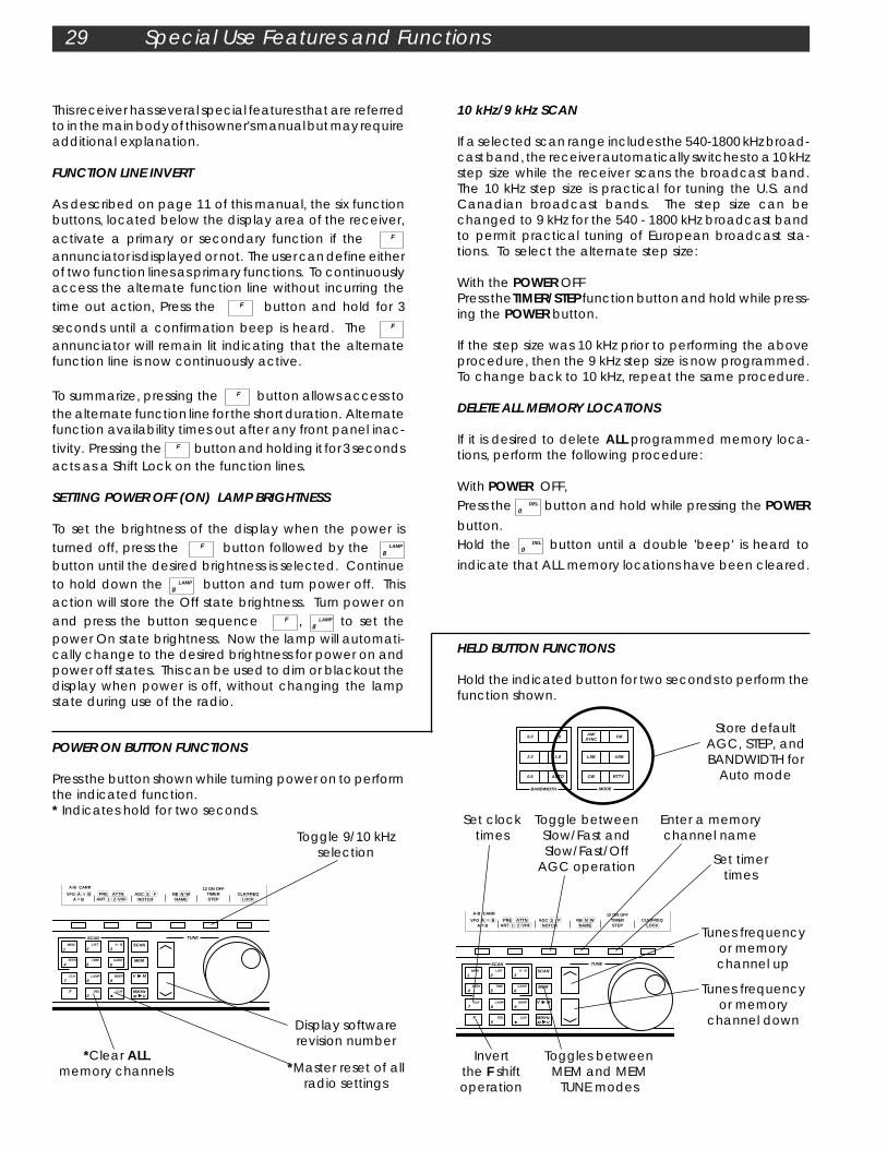
RLISTA-B
TIMECARR
TUNE
VFO A = B A = B
PRE ATTN ANT 1 2 VHF
AGC S F NOTCH
NB N W NAME
12 ON OFF
TIMER STEP
CLK/FREQ LOCK
TUNESCAN
SCAN
MEM
LIST
2 A - B
3
SEEK
4 TIME
5CARR
6
CLK
7LAMP
8BEEP
9
F DEL
0
V M
M V
M/KHz
MEM
1
CLR
RLISTA-B
TIMECARR
TUNE
VFO A = B A = B
PRE ATTN ANT 1 2 VHF
AGC S F NOTCH
NB N W NAME
12 ON OFF
TIMER STEP
CLK/FREQ LOCK
TUNESCAN
SCAN
MEM
LIST
2 A - B
3
SEEK
4 TIME
5CARR
6
CLK
7LAMP
8BEEP
9
F DEL
0
V M
M V
M/KHz
MEM
1
CLR
10 kHz/9 kHz SCAN
If a selected scan range includes the 540-1800 kHz broad-cast band, the receiver automatically switches to a 10 kHzstep size while the receiver scans the broadcast band.The 10 kHz step size is practical for tuning the U.S. andCanadian broadcast bands. The step size can bechanged to 9 kHz for the 540 - 1800 kHz broadcast bandto permit practical tuning of European broadcast sta-tions. To select the alternate step size:
With the POWER OFFPress the TIMER/STEP function button and hold while press-ing the POWER button.
If the step size was 10 kHz prior to performing the aboveprocedure, then the 9 kHz step size is now programmed.To change back to 10 kHz, repeat the same procedure.
DELETE ALL MEMORY LOCATIONS
If it is desired to delete ALL programmed memory loca-tions, perform the following procedure:
With POWER OFF,Press the DEL
0 button and hold while pressing the POWERbutton.Hold the DEL
0 button until a double 'beep' is heard to
indicate that ALL memory locations have been cleared.
29 Special Use Features and Functions
POWER ON BUTTON FUNCTIONS
Press the button shown while turning power on to performthe indicated function.* Indicates hold for two seconds.
Toggle 9/10 kHzselection
Set clocktimes
Toggle betweenSlow/Fast andSlow/Fast/Off
AGC operation
Enter a memorychannel name
Set timertimes
Tunes frequencyor memory
channel down
Tunes frequencyor memorychannel up
Invertthe F shiftoperation
Toggles betweenMEM and MEM
TUNE modes
HELD BUTTON FUNCTIONS
Hold the indicated button for two seconds to perform thefunction shown.
Store defaultAGC, STEP, andBANDWIDTH for
Auto mode
6.0 4.0 AM/ SYNC
FM
2.3 1.8 LSB USB
0.5 AUTO CW RTTY
BANDWIDTH MODE
This receiver has several special features that are referredto in the main body of this owner's manual but may requireadditional explanation.
FUNCTION LINE INVERT
As described on page 11 of this manual, the six functionbuttons, located below the display area of the receiver,activate a primary or secondary function if the F
annunciator is displayed or not. The user can define eitherof two function lines as primary functions. To continuouslyaccess the alternate function line without incurring thetime out action, Press the F button and hold for 3
seconds until a confirmation beep is heard. The F
annunciator will remain lit indicating that the alternatefunction line is now continuously active.
To summarize, pressing the F button allows access tothe alternate function line for the short duration. Alternatefunction availability times out after any front panel inac-tivity. Pressing the F button and holding it for 3 secondsacts as a Shift Lock on the function lines.
SETTING POWER OFF (ON) LAMP BRIGHTNESS
To set the brightness of the display when the power isturned off, press the F button followed by the LAMP
8
button until the desired brightness is selected. Continueto hold down the LAMP
8 button and turn power off. Thisaction will store the Off state brightness. Turn power onand press the button sequence F , LAMP
8 to set thepower On state brightness. Now the lamp will automati-cally change to the desired brightness for power on andpower off states. This can be used to dim or blackout thedisplay when power is off, without changing the lampstate during use of the radio.
Display softwarerevision number
*Clear ALLmemory channels *Master reset of all
radio settings

RS232C Interface 30
The receiver rear panel provides a common DB-9 con-nector which conforms to the RS-232C serial data com-munications standard with the receiver configured asDCE. This connector may be attached to a basic dumbASCII terminal or a personal computer such as an IBM XT/AT running a terminal emulation program such asPROCOMM PLUS TM or BITCOM TM. Standard BASIC terminalprograms will run equally well.
The interface provides complete control and program-ming capability of the receiver. Only the analog controlssuch as volume, RF gain, etc. are not controllable. Thereceiver front panel buttons and tuning wheel are nor-mally operable when the receiver is under computercontrol. The buttons and tuning wheel can be locked out,if desired, either by pressing the button sequence: F ,LOCK function line button or by use of the ‘LO’ computercommand.
Please refer to FIGURE 17 for interface connector pin out.
NOTE:The following additional items apply when using theRS232C Interface capability of the receiver:
WARNING:SHIELDED INTERFACE CABLES MUST BE USED WITH THISRECEIVER FOR FCC COMPLIANCE TO LIMITS FOR A CLASSB DIGITAL DEVICE.
When interfacing the receiver to a computer utilizing a 25pin male connector for the RS-232C serial port, the follow-ing wiring convention should be followed:
Computer DB25Connector
83220764522
Receiver DB9Connector
123456789
Note: This equipment has been tested and found tocomply with the limits for a Class B digital device, pursuantto Part 15 of the FCC rules. These limits are designed toprovide reasonable protection against harmful interfer-ence in a residential installation. This equipment gener-ates, uses and can radiate radio frequency energy and,if not installed and used in accordance with the instruc-tions, may cause harmful interference to radio communi-cations. However, there is no guarantee that interfer-ence will not occur in a particular installation. If thisequipment does cause harmful interference to radio ortelevision reception, which can be determined by turningthe equipment off and on, the user is encouraged to tryto correct the interference by one or more of the follow-ing measures:
- Reorient or relocate the receiving antenna.
- Increase the separation between the equipment andthe receiver.
- Connect the equipment into an outlet on a circuitdifferent from that to which the receiver is connected.
- Consult the dealer or an experienced radio/TV techni-cian for help.
FIGURE 17 RS232C Interface Connections
PROCOMM PLUSTM is registered to DATASTORMTechnologies, Inc.P.O. Box 1471Columbia, MO 65205
BITCOMTM is registered to BIT Software, Inc.830 Hillview Court, Suite 160Milpitas, CA 95035
Signal Description
Scan Feedback;+5 Volts = ReceiverUnsquelchedRx DATATx DATANo ConnectionGroundNo ConnectionNo ConnectionNo ConnectionGround
Pin
1
23456789
INTERFACE
RS - 232C
Rear Panel View
2 3 4 51
6 8 97

31 RS232C Interface cont'd.
RESPONSE
CR AND LFCR AND LFCR AND LFCR AND LFCR AND LFCR AND LFCR AND LFCR AND LFCR AND LFCR AND LFCR AND LFCR AND LF
NONENONE
CR AND LFCR AND LF
S SCR AND LF
CR, LF or NONECR AND LFCR AND LFCR AND LFCR AND LFCR AND LFCR AND LF
R8A.n CR LFCR AND LF
Scan ReportScan Report
CR AND LFCR AND LFCR AND LFCR AND LF
CR AND LF
CR AND LFCR AND LFCR AND LFCR AND LFCR AND LFCR AND LF
TR LF
CR AND LFCR AND LFCR AND LFCR AND LFCR AND LFCR AND LFCR AND LF
FUNCTION
1. Basic Radio ControlsAGC SettingAntenna selectionBandwidth selectionFrequency entryMode selectionNoise blanker settingNotch settingPower on/off (5)Quick Set (7)RF gain settingStep size selection (2)Synchronous detector setting (2)Tune Up (2)Tune DownVFO selectionVFO A = VFO B
2. Memory ManagementBlock Read (7)Block Store (7) *(10)Erase AllErase ChannelMem Tune ControlName ChannelName Mode ControlRecall ChannelStore (Program) Channel
3. Information RetrievalIdentify Receiver (5)Output Control (8)Report (9)Report the Scan List (9)4. Scan FunctionsScan Method (2)Scan Mode (2)Start/Stop Scan (2)Scan [Transfers the current VFO (A or B) to the A - B scan limits]Scan List [Allows entry of lists to scan - any 10 of a possible 44 lists ('00' - '43')
5. Clock & Timer FunctionsTimer DisableTimer EnableTimer Relay ControlActivate Relay on Squelch BreakLocal Time Report,[Entry]UTC Time Report,[Entry]Timer Time Report,[Entry]
6. MiscellaneousLock Front PanelLoad DefaultsSet AM BCB Step sizeSelect MHz/kHzSelect Frequency Display ModeSelect Time Display ModeSelect Display Brightness
=Enter key
=Enter key
=Enter key
COMMAND GROUP
AF, AS, AOA1, A2, AC
W0, W1, W2, W4, W6F[nnn.nnnnn],F[nnnnn.nn] or F[nnnnnnn]
M1, M2, M3, M4, M5, M6BF, BN, BW
NF, NOPF, PO
QdddddddG+, G-, G0
ST0, ST1, ST2, ST3, or STSF, SO
UD
VA, VBA E B
BR sss, eeeBS sss ddddddd
EA[Y]ECn[nn]CTF, CTO
NCcccccccNA, NIC[nnn]
PR [nnn]
IDOO, OF
R[A][F][C][M][SS][S][N][R]R (SL)
S1, S2, S3S4, S5, S6
SC, SCO, SCF SA, SB
SL XX, XX, XX, ...
TD[1,2]TE[1,2]TF, TO
TSF, TSOTL[hhmmss]TU[hhmmss]
T[1,2][F,O][hhmm]
LF, LOLD[Y]
SSE, SSUSM, SK
FRTILB
Index to Commands (listed by function group, then in alphabetical order of function)
Note: The Lock front panel commands (LO and LF) work as expected when locking and unlocking the front panel froma PC - (LO locks it and LF unlocks it). However, when locking and unlocking a scanned channel, LO toggles the lock onand off, and LF has no affect at all.

RS232C Interface cont'd. 32
NOTES:(1) All commands terminated by carriage return CR,except U and D. Commands ‘Cx’ and ‘Fxxxxxxx’ requirean optional Carriage Return as follows:- If ‘Cx’ is followed by a Carriage Return, response isimmediate.- If ‘Cxxx’ is entered, response is immediate (but note thatno Carriage Return was required in this case).(2) These commands may be used during scanning.Others are locked out.(3) A null entry (carriage return by itself) results in a LFresponse.Invalid commands result in a ‘Not recognized’ response.(4) Format: RS-232C levels at rear panel connector.9600 baud, half Duplex 1 start bit, 8 data, 1 stop bit, noparityData is ASCII encoded.(5) These commands allowed even if power is turned off(see PO/PF). Others are locked out.(6) Backspace can be used to correct typing error beforehitting return.(7) Commands Intended for use in computer control usehexadecimal data.(8) Causes a report from the receiver whenever anyreceiver setting is changed.(9) Report types may be entered in any combination forcustomized reports.*(10) Block Store might not work under PROCOMMPLUSTM. Use WindowsTM Terminal program or TelixTM pro-gram.
ASCII downloads are performed by selecting the‘Transfer’ menu and selecting the ‘Send Text File’. - OR -2) TELIXTM (V3.20) Instructions -Alt 0A
BCDEFGHIJKLMNO
Select ASCII Transfers:ABCDEFGHIJ
TelixTM V.20 was demonstrated to work with the Block Storecommand using the pacing character feature of TelixTM.The pacing character used is ‘*’ (decimal 42). This actionprevents the receiver from being overrun with data fromTelixTM.
The ASCII transfer setup parameter ‘E’ is set to 42. TheASCII transfer setup parameter ‘G’ is machinedependent. The delay of ‘999’ represents the greatestdelay and therefore ensures proper operation.
CTS handshaking is supported, but many PC programsoverrun the receiver’s RS232C buffer causing Block Storeoperations to fail when the overrun conditions exist.
Block Store download files are created using editorswhich support binary/hex editing modes or by using theBlock Read command to upload memory informationfrom the receiver.
Select Terminal optionsPort COM? Baud: 9600, Parity: None Data bits: 8, Stop bits: 1Emulate before translate table: OffDefault terminal type: ANSIStatus Line: BottomLocal echo: OnAdd line feeds after carriage returns: OffStrip high bit (in-coming data): OffReceived Backspace destructive: OffBackspace key sends: BSXON/XOFF software flow control: OffCTS/RTS hardware flow control: OffDSR/DTR hardware flow control: OffCompuserve Quick B transfers: OnZ Modem auto-downloads: OnAnswerback string
Strip high bit: OffRemote abort character: 0 (ASCII)Local echo: OffExpand blank lines: OffPace Character: 42 (ASCII)Line Pacing: 10Character Pacing: 999CR translation: NoneLF translation: NoneCR translation: None
NOTE that PROCOMM PLUSTM might not work with theBlock Store command. There are two suggestedmethods that will allow programming the Block Storecommand:
1) WINDOWSTM Terminal Instructions -The WINDOWSTM terminal can be used with the delayper character set to 1/10 second to permit ASCIIdownloads to function properly with Block Storecommands.
Under the ‘Settings’ menu, select ‘Text Transfers’. Under‘Flow Control’, select ‘A Character at a Time.
Under ‘Transfer a Character at at Time’, select ‘DelayBetween Characters 1 /10 second’.
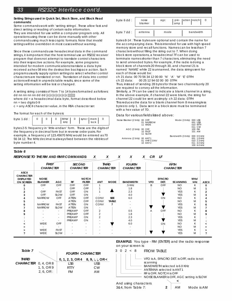
33 RS232C Interface cont'd.
Setting Strings used in Quick Set, Block Store, and Block Readcommands:Some commands work with ‘setting strings’. These allow fast anddirect setting or reading of certain radio information.They are intended for use within a computer program only. Alloperations using these can be done manually with othercommands using much less cryptic formats. Note that invalidsettings will be overridden in most cases without warning.
Since these commands use hexadecimal data in the commandstrings, it is important that the host terminal use an RS232 receiverprogram that does not attempt to translate control charactersinto their respective actions. For example, some programsintended for modem communications translate a data bytereceived as hex 08 into the destructive backspace action. Suchprograms usually supply option settings to select whether controlcharacters are translated or not. Translation of data into controlactions will result in unpredictable results, since some of thesetting information will be lost or changed.
A setting string consists of from 7 to 14 bytes formatted as follows:dd nn nn nn nn dd dd [c[c[c[c[c[c[c]]]]]]]where dd = a hexadecimal data byte, format described belownn = two digits 0-9c = any ASCII character value, in the R8A character set
The format for each of the bytes is:
bytes 2-5: frequency in ‘little-endian’ form. These are the digits ofthe frequency in decimal form but in reverse order pairs. Forexample, a frequency of 123.45670 MHz would be entered as 7056 34 12. The MHz decimal is always fixed between the nibbles ofbyte number 4.
bytes 8-14 : These bytes are optional and contain the name forthe accompanying data. This is intended for use with high speedmemory store and recall functions. Names can be less than 7characters without filling the string out to 7. When doingblock store operations, a hexadecimal 7F can be used toterminate names shorter than 7 characters, eliminating the needto send unneeded bytes. For example, if the radio is doing ablock store of channels 20 through 30, and channel 21 isnamed ‘NAME’ while 22 is unnamed, the data strings sent foreach of those would be:ch 21 data: 00 70 56 34 12 00 00 ‘N’ ‘A’ ‘M’ ‘E’ 07FHch 22 data: 00 25 12 94 02 00 00 07FHThus, instead of sending 28 bytes for these two channels,only 20are required to convey all the information.Similarly, a 7F can be used to indicate a blank channel in a string.In the above example, if channel 22 were blank, the string forchannel 22 could be sent as simply: ch 22 data: 07FHThis reduces the data for a blank channel from 8 meaninglessbytes to only 1. Data sent in a block store must be terminatedwith a hex value of 7D.
0, 1, 2, 3, OR 4LSBRTTYFM
8, 9, :, ;, OR <USBCWAM
0, 4, OR 81, 5, OR 92, 6, OR :
FOURTH CHARACTER
THIRDCHARACTER
Table 7 FROM TABLE
VFO is A, SYNCRO DET. is OFF, radio is notscanningBANDWIDTH selected is 6.0 KHzANTENNA selected is ANT 1RF is OFF, NOTCH is OFFNOISE BLANKER is OFF, AGC setting is SLOW
3 0 2 < 8
EXAMPLE: You type - RM (ENTER) and the radio responseon your screen is:
2 AM
<
Mode is AMAnd using characters3&4, from Table 7:
FOURTHCHARACTER
THIRDCHARACTER
BANDWIDTH.5 KHz
1.82.34.06.0---
0.51.82.34.06.0---
SYNCRODET.OFF
ON
OFF
ON
VFOB
A
ASCIICHARACTERDISPLAYEDON SCREEN
0123456789:;<=>?
ASCII0123456789:;<=>?
NOISEBLANKER
OFF-
OFFOFF
NARROW-
NARROWNARROW
----
WIDE-
WIDEWIDE
AGCOFF
-FAST
SLOWOFF
-FAST
SLOW----
OFF-
FASTSLOW
RFOFFOFFOFFOFF
ATTENATTENATTENATTEN
PREAMPPREAMPPREAMPPREAMP
----
NOTCHFILTEROFFOFFONONOFFOFFONONOFFOFFONON
----
SECONDCHARACTER
ANT111-
CONVCONVCONV
-222-----
MODE
SEETABLE
7
---
SCANNINGNONOYESYESNONOYESYESNONOYESYESNONOYESYES
MHz/kHzKMKMKMKMKMKMKMKM
FIFTHCHARACTER
FIRSTCHARACTER
RESPONSE TO THE RM AND RMR COMMANDS: X X X X X CR LFTable 6
byte 6 dd : 0notchattenpre-amp
noiseblanker
agc
byte 7 dd : antenna mode bandwidth
byte 1 dd : memlock
MHz/kHz
0 0 0 0 syncr 0Data for various fields listed above:Noise Blanker (2 bits):
AGC (2 bits):
Antenna (2 bits):
00 OFF01 NARROW11 WIDE
00 OFF10 FAST11 SLOW
00 ANT 101 VHF CONV10 ANT 2
Mode (3 bits):
Bandwidth (3 bits):
000 LSB001 USB010 RTTY011 CW100 FM101 AM
000 0.5 kHz001 1.8 kHz010 2.3 kHz011 4.0 kHz100 6.0 kHz

Glossary of Terms 34
1) AC Input - Alternating Current power source availableat wall outlet sockets.
2) AM - Amplitude Modulated signals in which the infor-mation or intelligence being transmitted changes theinstantaneous amplitude of the transmitted carrier.Not to be confused with the AM Broadcast Band (fre-quencies of 540 to 1610 kHz).
3) AGC - Automatic Gain Control which is employed inreceivers to adjust the amount of gain in the receiver'scircuitry to prevent distortion and maintain a nearly con-stant audio volume level over wide variations in receivedsignal strength.
4) Attenuation - Loss, as applied in the text of this manual,added prior to the input stages of the receiver to reducethe level of very strong signals that may occur on certainbands, in certain locations, at certain times or a combina-tion of all three factors. Each 10 dB (decibel) step reducesthe power of the received signal by a factor of ten.
5) CW - Continuous Wave transmission signals. Actually,the signal is keyed on and off at precise intervals toconvey information. Morse code is the most common CWsignal.
6) DC Input - Direct Current power source such as isavailable from batteries or regulated power supplies.Lead acid storage batteries, such as employed in carsand boats, have a 12-14 volt DC output which is theproper operating voltage for the receiver's DC input.Another requirement of the battery is its AMP-HR rating. Todetermine the number of hours of operation before bat-tery recharging is required, divide the AMP-HR rating ofthe battery by (2 AMPS) the current requirement of thereceiver.
7) Dynamic Range - Ability of the receiver to faithfullyreproduce high quality audio over a wide range of signalstrength conditions - from very weak signals to very strongsignals.
8) Frequency - Rate of reoccurrence in hertz or cycles/second of electromagnetic wave or carrier.
9) FM - Frequency Modulated signals in which the infor-mation or intelligence being transmitted changes theinstantaneous frequency of the transmitter carrier.Not to be confused with the FM Broadcast Band (frequen-cies of 88 to 108 MHz).
10) High Q, Electronically Switched Filter - A multi band-width filter with high adjacent channel attenuationswitched electronically.
11) GMT - Greenwich Mean Time.
12) LCD - Liquid-crystal display - composed of two
parallel glass plates with conductive coatings sandwich-ing a liquid-crystal compound between them. The com-pound becomes opaque and reflective when subjectedto an electric field. LCD displays are used as informationdisplays on many types of electronic equipment.
13) LSB - Lower Side Band, the mirror image of the USBcontaining all of the modulation information of amplitudemodulation in one half the bandwidth. The lower half,excluding the carrier, of an AM signal.
14) Notch - A response producing attenuation of signalsover a narrow range of frequencies.
15) Passband Offset - A frequency conversion techniquewhich skews the desired channel off center of the detec-tion filters allowing low or high frequency components tobe selectively attenuated.
16) Passive Double Balanced Mixer - A frequency conver-sion device requiring a locally generated oscillator (LO) tooperate. An incoming RF signal is shifted relative to the LOproducing an intermediate or IF frequency.
17) RF - Radio frequency
18) RS232 - Electronics Industries Association standardphysical-level interface between DTE (terminal) and DCE(modem).
19) RTTY - Radio Teletype communications.
20) Squelch - A user controlled adjustment which mutesthe audio output below a certain signal strength.
21) Synchronous Detector - An amplitude modulationdetector which utilizes a replica of the original transmittedcarrier signal to improve the reception of weak signals.
22) Synthesized - Capable of generating a large numberof different output frequencies, all related to a single,highly stable reference source.
23) Up Conversion - A frequency conversion techniquethat translates an incoming RF signal to a higher fre-quency.
24) USB - Upper side band, the mirror image of the LSBcontaining all of the modulation information of amplitudemodulation in one half the band width. The upper half,excluding the carrier, of an AM signal.
25) UTC - Universal Time Coordinated.
26) VFO - Variable frequency oscillator
27) VHF - Very High Frequency band extends from ap-proximately 30MHz to 300 MHz.

35 Suggested References
SUGGESTED REFERENCES
1) Passport to World Band RadioPublished by:International Broadcasting Services, Ltd.P. O. Box 300Penn's Park, Pennsylvania 18943
2) World Radio TV HandbookVolume 37Published by:Billboard Publications Inc.1515 BroadwayNew York, NY 10036
3) The ARRL Antenna BookPublished by:The American Radio Relay LeagueNewington, CT USA 06111Copyright © 1988 by The American Radio Relay LeagueLibrary of Congress Catalog Card Number: 55-8966
4) The ARRL HandbookPublished by:The American Radio Relay LeagueNewington, CT USA 06111Copyright © 1989 by The American Radio Relay LeagueLibrary of Congress Catalog Card Number: 41-3345
5) Radio Interference - How to Find it and Cure itPublished by:The American Radio Relay LeagueNewington, CT 06111U. S. A.
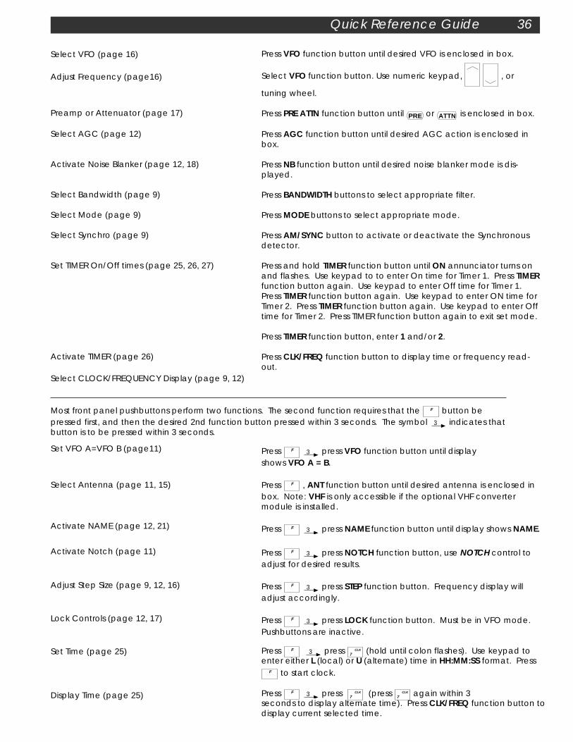
Quick Reference Guide 36
Press VFO function button until desired VFO is enclosed in box.
Select VFO function button. Use numeric keypad, , or
tuning wheel.
Press PRE ATTN function button until PRE or ATTN is enclosed in box.
Press AGC function button until desired AGC action is enclosed inbox.
Press NB function button until desired noise blanker mode is dis-played.
Press BANDWIDTH buttons to select appropriate filter.
Press MODE buttons to select appropriate mode.
Press AM/SYNC button to activate or deactivate the Synchronousdetector.
Press and hold TIMER function button until ON annunciator turns onand flashes. Use keypad to to enter On time for Timer 1. Press TIMERfunction button again. Use keypad to enter Off time for Timer 1.Press TIMER function button again. Use keypad to enter ON time forTimer 2. Press TIMER function button again. Use keypad to enter Offtime for Timer 2. Press TIMER function button again to exit set mode.
Press TIMER function button, enter 1 and/or 2.
Press CLK/FREQ function button to display time or frequency read-out.
Select VFO (page 16)
Adjust Frequency (page16)
Preamp or Attenuator (page 17)
Select AGC (page 12)
Activate Noise Blanker (page 12, 18)
Select Bandwidth (page 9)
Select Mode (page 9)
Select Synchro (page 9)
Set TIMER On/Off times (page 25, 26, 27)
Activate TIMER (page 26)
Select CLOCK/FREQUENCY Display (page 9, 12)
Most front panel pushbuttons perform two functions. The second function requires that the F button bepressed first, and then the desired 2nd function button pressed within 3 seconds. The symbol 3 indicates thatbutton is to be pressed within 3 seconds.
Press F 3 press VFO function button until displayshows VFO A = B.
Press F , ANT function button until desired antenna is enclosed inbox. Note: VHF is only accessible if the optional VHF convertermodule is installed.
Press F 3 press NAME function button until display shows NAME.
Press F 3 press NOTCH function button, use NOTCH control toadjust for desired results.
Press F 3 press STEP function button. Frequency display willadjust accordingly.
Press F 3 press LOCK function button. Must be in VFO mode.Pushbuttons are inactive.
Press F 3 press CLK
7 (hold until colon flashes). Use keypad toenter either L (local) or U (alternate) time in HH:MM:SS format. Press
F to start clock.
Press F 3 press CLK
7 (press CLK
7 again within 3seconds to display alternate time). Press CLK/FREQ function button todisplay current selected time.
Set VFO A=VFO B (page11)
Select Antenna (page 11, 15)
Activate NAME (page 12, 21)
Activate Notch (page 11)
Adjust Step Size (page 9, 12, 16)
Lock Controls (page 12, 17)
Set Time (page 25)
Display Time (page 25)
37 Quick Reference Guide
Dim Lamp (10,29)
Disable Beep (10)
MEMORY FUNCTIONS
Program Memory Channel (page 21)
Recall Memory Channel (page 21)
Recall Memory Tune Channel (page 21)
Move Memory to VFO (page 21)
Lock Memory Channel (page 21)
Delete Memory Channel (page 21)
Select VFO & mode, adjust frequency & bandwidth.Press V M (MEM will flash), 3 use keypad to enter 3 digit memorychannel number. Use the Tuning Wheel to enter character at each
location for NAME. Press to advance cursor and press to
backspace. Press V M to exit.
Press MEM use keypad to enter channel number, or use or the
tuning wheel.
Press MEM (hold until MEM TUNE is displayed). Use keypad or .
Use tuning wheel to change frequency.
Press M VM/KHz . Will move memory contents to last used VFO.
Select memory channel to be locked, F 3 press LOCK.
Select memory channel to be deleted. Press F 3 press DEL
0
(hold until 2nd beep).
SCAN MODESAll SCAN modes require selecting one of three SCAN METHODS. Select desired SCAN MODE and then select 'SEEK','TIME' or 'CARRIER'.
Scan Memory (page 22)
Scan List (page23)
Scan Multiple Lists (page 23)
Scan A - B (page24)
Other Controls Used in Scan Mode.
Passband Offset
Squelch/RF
Adjust for optimum reception.
Set squelch counterclockwise. Adjust RF (gain) counterclockwise until S-meterindicates desired signal level to trip squelch. Advance the Squelch controlclockwise until the audio just quiets. Advance the RF (gain) fully clockwise.
Press F 3 press MEM
1 then select method,
Press F 3 press SEEK
4 or press F 3 press TIME
5 or
Press F 3 press CARR
6 . Press SCAN .
Press F 3 press SCAN
LIST
2 then select method,
Press F 3 press SEEK
4 or press F 3 press TIME
5 or
Press F 3 press CARR
6 . Press SCAN .
Press F 3 press SCAN
LIST
2 , Enter number, to enter additional
number, to review list. Select method. Press SCAN .
Press F 3 press SEEK
4 or press F 3 press TIME
5 or
Press F 3 press CARR
6 or press SCAN .
Press F 3 press A - B
3 , Enter one endpoint frequency.
Press or , Enter second endpoint frequency.
Press SCAN .
Press F 3 press LAMP
8 Press until dial lighting is at desired level.
Press F 3 press BEEP
9 to enable or disable beep.

Troubleshooting 38
Symptom
No front panel display or lightswhen power is depressed
Scrambled front panel displaywhen power is depressed
No signals heard when antennais connected or sensitivity low
S meter indication, but remainsconstant
S meter indication, but no soundheard
SSB signals have excessivelyhigh or low frequency response
No front panel operation i.e.tuning, frequency entry, etc.
Timer does not operate
Direct frequency entry will not work
Corrective Action
A) Check power supply cablesB) Check fuseC) Contact service
A) Unplug from power source and re-connect to reset microprocessor
A) Turn squelch counterclockwiseB) Select correct antenna inputC) Turn off RF ATTND) Turn RF gain clockwise
A) Turn RF gain clockwise
A) Check mode selectionB) Check external speaker switch onrear panel
A) Center PASSBAND OFFSET control
A) Press F ”LOCK” to unlock frontpanel
A) Program timer ON/OFF times
A) Press F for confirmation beepand F annunciator not displayed
Probable Cause
A) Power connectionB) Blown supply fuse
A) Microprocessor malfunction
A) Squelch enabledB) Incorrect antenna input selectedC) RF ATTN enabledD) RF gain improperly set
A) RF gain improperly set
A) Improper mode selectedB) External speaker selectedC) Squelch enabled
A) PASSBAND OFFSET improperly set
A) Lock enabled
A) Timer not properly setB) Alternate clock selected
A) Alternate button functions enabledi.e.) F is displayed
TROUBLESHOOTING
R8A Special Display Messages
"PWRLOSL" or "PWRLOSU" (power lost) indicates that powerhas been disrupted to the receiver and the clocks havelost their time settings. There is no problem with thereceiver, and it may be operated as normal. To extinguishthis message, simply reset the clocks.
"PWRFAIL" (Power Fail) indicates that the power suppliedto the receiver does not meet the specified requirements.This could be caused by an improperly selected AC linevoltage, low AC line voltage (brown out), or low DCvoltage. Normal operations of the receiver are halted inthe "PWRFAIL" mode. To return to normal operation,disconnect the receiver from the power source. Makesure the proper AC Voltage range is selected from therear panel switch, then reconnect the power.Continued "PWRFAIL" messages under a known good
power source could indicate receiver power supply prob-lems. Should this occur, contact the Service Department.
"UNLOCKD" (unlocked) indicates that the synthesizer ofthe phased locked loop circuit is not locking to the properfrequency. If this should occur with the receiver, contactthe Service Department with details on what operationsare affected.

39 Service
SERVICE INFORMATION
You may contact the R. L. DRAKE Service Department foradditional information or assistance by calling (513)746-6990, Monday through Friday, 8:00 A.M. -5:00 P.M. EST, except on holidays.
You may also contact the R. L. DRAKE Service Departmentby E-mail at the following address:[email protected]
or by Telefax:+1 (513) 743-4576.
Should you want to return your unit for service, packagethe receiver carefully using the original carton or othersuitable container. Write your return address clearly onthe shipping carton and on an enclosed cover letterdescribing the service required, symptoms or problems.Also include your daytime telephone number and a copyof your proof of purchase.
The receiver will be serviced under the terms of the R. L.Drake Company Limited Warranty and returned to you.

Warranty 40
ONE YEAR LIMITED WARRANTY
R. L. DRAKE COMPANY warrants to the original purchaserthis product shall be free from defects in material orworkmanship for one year from the date of original pur-chase.
During the warranty period the R. L. DRAKE COMPANY oran authorized Drake service facility will provide, free ofcharge, both parts and labor necessary to correct de-fects in material and workmanship. At its option, R. L.Drake Company may replace a defective unit.
To obtain such warranty service, the original purchasermust:
(1) Complete and send in the Warranty Registration Cardwithin ten (10) days of purchase.
(2) Notify the R. L. DRAKE COMPANY or the nearest autho-rized service facility, as soon as possible after discovery ofa possible defect, of:(a) the model and serial number.(b) the identity of the seller and the approximate date ofpurchase.(c) a detailed description of the problem, including de-tails on the electrical connection to associated equip-ment and the list of such equipment.
(3) Deliver the product to the R. L. DRAKE COMPANY or thenearest authorized service facility, or ship the same in itsoriginal container or equivalent, fully insured and shippingcharges prepaid.
Correct maintenance, repair, and use are important toobtain proper performance from this product. Thereforecarefully read the Instruction Manual. This warranty doesnot apply to any defect that R. L. DRAKE COMPANYdetermines is due to:
(1) Improper maintenance or repair, including the instal-lation of parts or accessories that do not conform to thequality and specification of the original parts.
(2) Misuse, abuse, neglect or improper installation.
(3) Accidental or intentional damage.
All implied warranties, if any, including warranties of mer-chantability and fitness for a particular purpose, termi-nate one (1) year from the date of the original purchase.
The foregoing constitutes R. L. DRAKE COMPANY’S entireobligation with respect to this product, and the originalpurchaser shall have no other remedy and no claim forincidental or consequential damages, losses or expenses.Some states do not allow limitations on how long animplied warranty lasts or do not allow the exclusions orlimitation of incidental or consequential damages, so theabove limitation and exclusion may not apply to you.
This warranty gives you specific legal rights and you mayalso have other rights which vary from state to state.This warranty shall be construed under the laws of Ohio.

®
R. L. Drake Company230 Industrial Drive
Franklin, Ohio 45005 U.S.A.Customer Service and Parts Telephone:
+1 (513) 746-6990Telefax:
+1 (513) 743-4576World Wide Web Site:
http://www.rldrake.com