OWNER’S MANUAL - Electric Generators Direct · Generator LIT-19626-01-67 PRINTED ON RECYCLED...
58
Generator LIT-19626-01-67 7CG-28199-14 EF1000iS OWNER’S MANUAL Read this manual carefully before operating this machine.
Transcript of OWNER’S MANUAL - Electric Generators Direct · Generator LIT-19626-01-67 PRINTED ON RECYCLED...
Generator
LIT-19626-01-677CG-28199-14PRINTED ON RECYCLED PAPER
PRINTED IN JAPAN2011.04-0.5×1 !
(E)
EF1000iS
OWNER’S MANUAL
Read this manual carefully before operating this machine.
7CG-28199-14_hyoshi 11.4.18 10:14 Page 1

Read this manual carefully before operating this machine. This manualshould stay with this machine if it is sold.
7CG-28199-14_hyoshi 11.4.18 10:14 Page 2

AE00012
IDENTIFICATION NUMBER RECORDSRecord your Primary I.D., and serial num-bers in the spaces provided, to assist youin ordering spare parts from a Yamahadealer.Also record and keep these I.D. numbersin a separate place in case your machineis stolen.
AE00011
MACHINE IDENTIFICATIONThe machine serial number is stamped inthe location as shown.
TIPThe first three digits of these numbers arefor model identification; the remaining dig-its are the unit production number. Keep arecord of these numbers for referencewhen ordering parts from a Yamaha deal-er.
AE00002
INTRODUCTION
Congratulations on your purchase of your new Yamaha.This manual will provide you with a good basic understanding of the operation andmaintenance of this machine.If you have any questions regarding the operation or maintenance of your machine,please consult a Yamaha dealer.
PRI-I.D. NUMBER
PRI-I.D.CODE SERIAL No.
EF1000iSOWNER’S MANUAL
© 2011 by Yamaha Motor Corporation, U.S.A.1st Edition, February 2011
All rights reserved. Any reprinting or unauthorized usewithout the written permission of
Yamaha Motor Corporation, U.S.A.is expressly prohibited.
Printed in Japan.P/N LIT-19626-01-67
MODEL
790-065b
7CG-24163-00
AE00022
7CG-28199-14 11.3.21 14:56 Page A-1
Particularly important information is distin-guished in this manual by the followingnotations.
This is the safety alert symbol. It isused to alert you to potential personalinjury hazards. Obey all safety mes-sages that follow this symbol to avoidpossible injury or death.
A WARNING indicates a hazardous sit-uation which, if not avoided, couldresult in death or serious injury.
A NOTICE indicates special precau-tions that must be taken to avoid dam-age to the machine or other property.
TIPA TIP provides key information to makeprocedures easier or clearer.
NOTICE
WARNING
AE00032
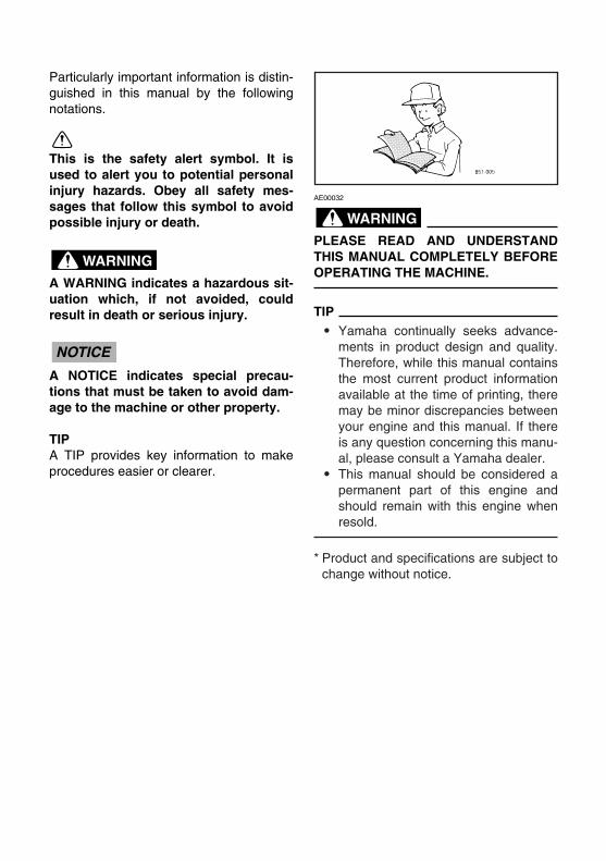
PLEASE READ AND UNDERSTANDTHIS MANUAL COMPLETELY BEFOREOPERATING THE MACHINE.
TIP9 Yamaha continually seeks advance-
ments in product design and quality.Therefore, while this manual containsthe most current product informationavailable at the time of printing, theremay be minor discrepancies betweenyour engine and this manual. If thereis any question concerning this manu-al, please consult a Yamaha dealer.
9 This manual should be considered apermanent part of this engine andshould remain with this engine whenresold.
* Product and specifications are subject tochange without notice.
WARNING
7CG-28199-14 11.3.21 14:56 Page A-2

AE00041
CONTENTS
SPARK PLUG INSPECTION.............24
CARBURETOR ADJUSTMENT.........25
ENGINE OIL REPLACEMENT ..........25
MUFFLER SCREEN AND SPARKARRESTER .......................................27
AIR FILTER........................................29
FUEL TANK FILTER..........................30
TROUBLESHOOTING..........................31
STORAGE.............................................33
DRAIN THE FUEL .............................33
ENGINE .............................................35
EXHAUST EMISSION CONTROL SYSTEM AND COMPONENTS ............36
SPECIFICATIONS ................................37
DIMENSIONS ....................................37
ENGINE .............................................37
GENERATOR ....................................37
WIRING DIAGRAM...............................38
YAMAHA MOTOR CORPORATION,U.S.A. EF SERIES GENERATORS 3-YEAR LIMITED WARRANTY ............39
YAMAHA OUTDOOR POWER EQUIPMENTCALIFORNIA EVAPORATIVE EMISSION CONTROL WARRANTY STATEMENT ..................42
YAMAHA MOTOR CORPORATION,U.S.A.SMALL OFF ROAD ENGINESCALIFORNIA EMISSION CONTROL WARRANTY.......................43
YAMAHA EXTENDED SERVICE (Y.E.S.)..................................................47
LOCATION OF IMPORTANT LABELS ..................................................1
SAFETY INFORMATION........................2
EXHAUST FUMES ARE
POISONOUS .......................................2
FUEL IS HIGHLY FLAMMABLE ANDPOISONOUS .......................................3
ENGINE AND MUFFLER MAY
BE HOT................................................3
ELECTRIC SHOCK PREVENTION.....4
CONNECTION NOTES .......................5
CONNECTION.....................................5
EXTENSION CORD NOTES ...............5
DESCRIPTION........................................6
CONTROL PANEL...............................6
ENGINE SWITCH................................7
OIL WARNING LIGHT (red).................7
ECONOMY CONTROL SWITCH.........7
DC PROTECTOR ................................8
FUEL TANK CAP AIR VENT KNOB....8
FUEL COCK KNOB .............................9
PRE-OPERATION CHECK...................10
FUEL..................................................10
ENGINE OIL ......................................12
GROUND (earth) TERMINAL ............12
OPERATION .........................................13
STARTING THE ENGINE..................13
APPLICATION RANGE .....................15
CONNECTION...................................16
OVERLOAD INDICATOR LIGHT(red) ..................................................17
BATTERY CHARGING......................18
STOPPING THE ENGINE .................21
PERIODIC MAINTENANCE .................22
MAINTENANCE CHART ...................22
7CG-28199-14 11.3.21 14:56 Page A-3

– 1 –
4 58 3 2
6 7 1
HOT EXHAUST7VV-28176-10
AE00062
LOCATION OF IMPORTANT LABELS
Please read the following labels carefully before oper-ating this generator.
TIPMaintain or replace safety and instruction labels, asnecessary.
WARNINGq
7CG-24162-10
Read the owner’s manual and all labels before operating.8Only operate in well-ventilated areas.Exhaust gas contains poisonous carbon monoxide.8
Check for spilled fuel or fuel leaks.8Stop engine before refueling.8Do not operate near flammable materials.8Electrocution can occur if generator is used in rain, snow,or near water. Keep this unit dry at all times.8
Electrocution or property damage can occur:Do not connect this generator to any building’s electricalsystem unless an isolation switch has been installed by alicensed electrician. Refer to the owner’s manual.
8
When operating the generator:Never place a partition or other barrier around the generator.Do not cover the generator with a box.Do not place any objects on the generator.
8
2 6
The air index of this engine is 3(California only)
MOST CLEAN LEAST CLEAN0 2 4 6 8 10
Note: The lower the air index, the less the pollution.This engine is certified to be emissions compliantfor the following use:
Check owner's manual for further details.( *** HOURS) ( *** HOURS) ( *** HOURS)MODERATE INTERMEDIATE EXTENDEDX
EMISSION CONTROL INFORMATIONYAMAHA MOTOR POWERED PRODUCTS CO.,LTD.
emission regulations for small off-road engines.This engine meets 20** California exhaust and evaporative
THIS ENGINE MEETS U.S. EPA EXH EVP REGS FOR 20**.
EVAP F: ********EF: ***********
EMISSION CONTROL SYSTEM: **DISPLACEMENT: *** cc
EMISSION COMPLIANCE PERIOD : *** HOURS
This engine is certified to operate on unleaded gasoline.
No other adjustments needed.ENGINE OIL: SAE***** TYPE : **
5
4
OIL
EF1000isAC output 60Hz Rated 900VA 120V Phase SingleDC output 12V 8AFuel Gasoline
YAMAHA MOTOR POWERED PRODUCTS CO.,LTD.MADE IN JAPAN
7VV-24164-11
3
STARTING INSTRUCTION
8Disconnect all
electrical devices.
Turn ECON. switch to OFF
Open fuel cap vent
Turn fuel knob ON
Turn engine switch to ON
Pull choke knob out
Pull recoil starter
Push choke knob in
8
8
8
8
8
8
8
7CG-25134-10
7
1 DANGERUsing a generator indoors CAN KILL YOU IN MINUTES.
Generator exhaust contains carbon monoxide.This is a poison you cannot see or smell.
NEVER use inside a home or garage, EVEN IF doors and windows are open.
Only use OUTSIDE and far away from windows, door, and vents.
NOTICEUse the specified spark plug only.
Specified plug:CR4HSB(NGK)
8
7CG-28199-14 11.3.21 14:56 Page 1
– 2 –
AE00071
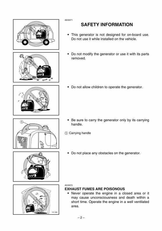
SAFETY INFORMATION
9 This generator is not designed for on-board use.Do not use it while installed on the vehicle.
9 Do not modify the generator or use it with its partsremoved.
9 Do not allow children to operate the generator.
741-077
19 Be sure to carry the generator only by its carrying
handle.
1 Carrying handle
9 Do not place any obstacles on the generator.
741-080
AE00072
EXHAUST FUMES ARE POISONOUS9 Never operate the engine in a closed area or it
may cause unconsciousness and death within ashort time. Operate the engine in a well ventilatedarea.
7CG-28199-14 11.3.21 14:56 Page 2
– 3 –
AE01018
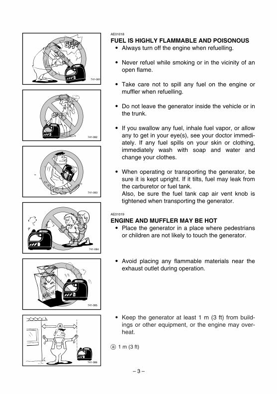
FUEL IS HIGHLY FLAMMABLE AND POISONOUS9 Always turn off the engine when refuelling.
9 Never refuel while smoking or in the vicinity of anopen flame.
9 Take care not to spill any fuel on the engine ormuffler when refuelling.
9 Do not leave the generator inside the vehicle or inthe trunk.
9 If you swallow any fuel, inhale fuel vapor, or allowany to get in your eye(s), see your doctor immedi-ately. If any fuel spills on your skin or clothing,immediately wash with soap and water andchange your clothes.
9 When operating or transporting the generator, besure it is kept upright. If it tilts, fuel may leak fromthe carburetor or fuel tank.Also, be sure the fuel tank cap air vent knob istightened when transporting the generator.
741-081
741-082
741-083
741-084
741-085
AE01019
ENGINE AND MUFFLER MAY BE HOT9 Place the generator in a place where pedestrians
or children are not likely to touch the generator.
9 Avoid placing any flammable materials near theexhaust outlet during operation.
741-086
a
9 Keep the generator at least 1 m (3 ft) from build-ings or other equipment, or the engine may over-heat.
a 1 m (3 ft)
7CG-28199-14 11.3.21 14:56 Page 3

– 4 –
741-088
741-089
AE01020
ELECTRIC SHOCK PREVENTION9 Never operate the engine in rain or snow.
9 Do not operate the engine with a dust cover orother objects covering it.
9 When covering the generator, be sure to do soonly after the engine and muffler have completelycooled down.
9 Never touch the generator with wet hands or elec-trical shock will occur.
741-087
1
9 Connect the ground lead of the generator to theground terminal and connect the end to theground electrode buried in the ground.
1 Ground (earth) terminal
7CG-28199-14 11.3.21 14:56 Page 4

– 5 –
1
2
1
2
741-090
AE00088
CONNECTION NOTES9 Avoid connecting the generator to commercial
power outlet.
9 Avoid connecting the generator in parallel with anyother generator.
1 Correct2 Incorrect
AE00091
CONNECTION
Before the generator can be connected to a build-ing’s electrical system, a licensed electrician mustinstall an isolation (transfer) switch in the build-ing’s main fuse box. The switch is the connectionpoint for generator power and allows selection ofgenerator or main line power to the building. Thiswill prevent the generator from charging the mainpower line (backfeeding) when the main powersupply has failed or has been turned off for linerepair. Backfeeding can electrocute or injure linemaintenance personnel. Also, generator and build-ing electrical system damage can occur when nor-mal operating power returns if unit is used withoutan isolation switch.
WARNING
AE00086
EXTENSION CORD NOTES9 Extension cords should be protected by a tough
flexible rubber sheath (IEC 245) or the equivalentto withstand mechanical stresses.
7CG-28199-14 11.3.21 14:56 Page 5

– 6 –
793-104a
1
6
3 4
7
8
52
9
1
793-105a
w
0
2
q
35
AE00101
DESCRIPTION
1 2 3 4
q 0 9 8 7 793-106a
5 6
AE00103
CONTROL PANEL1 Overload indicator light2 AC pilot light3 Oil warning light4 Engine switch5 Choke knob6 Fuel cock knob7 Ground (earth) terminal8 Economy control switch9 DC protector0 AC receptacleq DC receptacle
1 Fuel tank2 Fuel tank cap3 Fuel tank cap air vent knob4 Spark plug5 Carrying handle6 Fuel cock knob7 Choke knob8 Ground (earth) terminal9 Recoil starter0 Air filter coverq Oil filler capw Muffler
7CG-28199-14 11.3.21 14:56 Page 6

AE00111
OIL WARNING LIGHT (red)When the oil level falls below the lower level, the oilwarning light (red) comes on and then the enginestops automatically. Unless you refill with oil, theengine will not start again.
TIPIf the engine stalls or does not start, turn the engineswitch to “ON” and then pull the recoil starter. If the oilwarning light flickers for a few seconds, the engine oilis insufficient. Add oil and restart.
– 7 –
763-221
1
2
700-115
763-220
1
2
AE00939
ENGINE SWITCHThe engine switch controls the ignition system.
1 7 “ON”Ignition circuit is switched on.The engine can be started.
2 5 “STOP”Ignition circuit is switched off.The engine will not run.
AE00988
ECONOMY CONTROL SWITCH 1 I “ON”When the economy control switch is turned to “ON”,the economy control unit controls the engine speedaccording to the connected load. The results are betterfuel consumption and less noise.
2 3 “OFF”When the economy control switch is turned to “OFF”,the engine runs at the rated r/min (5,000 r/min) regard-less of whether there is a load connected or not.
7CG-28199-14 11.3.21 14:56 Page 7

– 8 –
TIPThe economy control switch must be turned to “OFF”when using electric devices that require a large start-ing current, such as a compressor or a submersiblepump.
AE01099
DC PROTECTORThe DC protector turns “OFF” automatically whenelectric device being connected to the generator isoperating and current above the rated flows. To usethis equipment again, turn on the DC protector bypressing its button to “RESET”.
1 I “RESET” Direct current is output. (This is the default position.)
2 3 “OFF” Direct current is not output.
Reduce the load of the connected electric devicebelow the specified rated output of the generator ifthe DC protector turns off. If the DC protectorturns off again, stop using the device immediatelyand consult a Yamaha dealer.
NOTICE
763-224a
763-238a
1
2
707-096
2
1
AE01021
FUEL TANK CAP AIR VENT KNOBThe fuel tank cap is provided with an air vent knob tostop fuel flow.The air vent knob must be turned 1 turn counterclock-wise from the tightened position. This will allow fuel toflow to the carburetor and the engine to run.When the engine is not in use, tighten the air ventknob clockwise until it is finger-tight to stop fuel flow.
1 Air vent knob2 Fuel tank cap
7CG-28199-14 11.3.21 14:56 Page 8
– 9 –
763-227
1 2
3
707-098
OFF
ON5 4
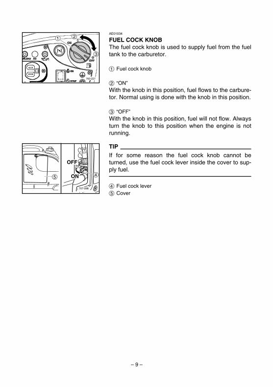
AE01034
FUEL COCK KNOBThe fuel cock knob is used to supply fuel from the fueltank to the carburetor.
1 Fuel cock knob
2 “ON”With the knob in this position, fuel flows to the carbure-tor. Normal using is done with the knob in this position.
3 “OFF”With the knob in this position, fuel will not flow. Alwaysturn the knob to this position when the engine is notrunning.
TIPIf for some reason the fuel cock knob cannot beturned, use the fuel cock lever inside the cover to sup-ply fuel.
4 Fuel cock lever5 Cover
7CG-28199-14 11.3.21 14:56 Page 9
741-091
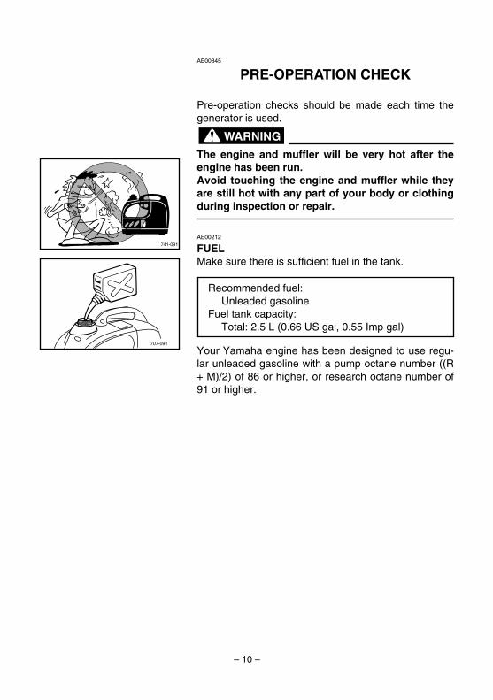
AE00845
PRE-OPERATION CHECK
Pre-operation checks should be made each time thegenerator is used.
The engine and muffler will be very hot after theengine has been run.Avoid touching the engine and muffler while theyare still hot with any part of your body or clothingduring inspection or repair.
AE00212
FUELMake sure there is sufficient fuel in the tank.
Your Yamaha engine has been designed to use regu-lar unleaded gasoline with a pump octane number ((R+ M)/2) of 86 or higher, or research octane number of91 or higher.
WARNING
– 10 –
707-091
Recommended fuel:Unleaded gasoline
Fuel tank capacity:Total: 2.5 L (0.66 US gal, 0.55 Imp gal)
7CG-28199-14 11.3.21 14:56 Page 10

– 11 –
707-095
9 Fuel is highly flammable and poisonous.Check “SAFETY INFORMATION” (See page 3)carefully before refueling.
9 Do not fill above the “LEVEL” mark (red) in thefuel filter or it may overflow when the fuelheats up later and expands.
9 After refueling, make sure the tank cap is tight-ened securely.
1 “LEVEL” mark (red)
9 Immediately wipe off spilled fuel with a clean,dry, soft cloth, since fuel may deterioratepainted surfaces or plastic parts.
9 Use only unleaded gasoline. The use of leadedgasoline will cause severe damage to internalengine parts.
NOTICE
WARNING
707-092
1
7CG-28199-14 11.3.21 14:56 Page 11
700-116
700-119
1
1
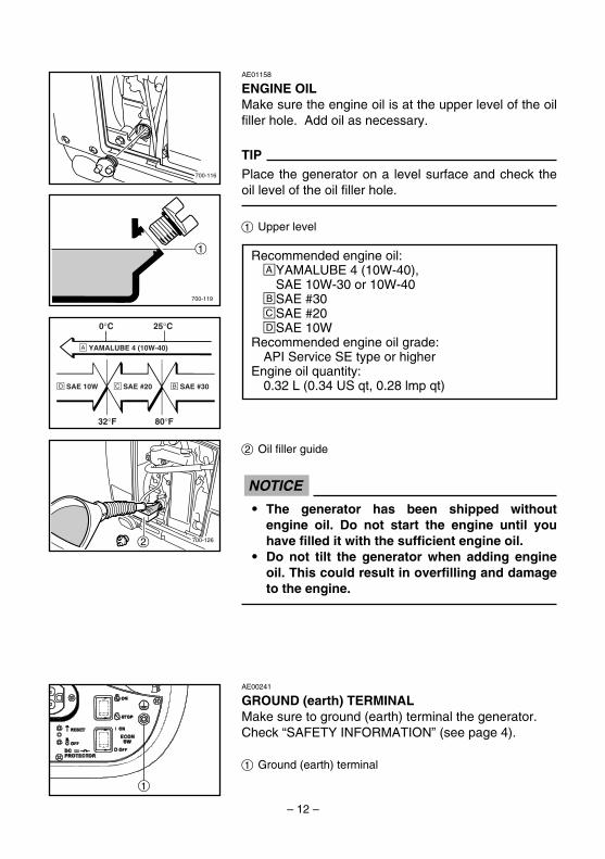
AE01158
ENGINE OILMake sure the engine oil is at the upper level of the oilfiller hole. Add oil as necessary.
TIPPlace the generator on a level surface and check theoil level of the oil filler hole.
1 Upper level
2 Oil filler guide
9 The generator has been shipped withoutengine oil. Do not start the engine until youhave filled it with the sufficient engine oil.
9 Do not tilt the generator when adding engineoil. This could result in overfilling and damageto the engine.
NOTICE
– 12 –
0°C
å YAMALUBE 4 (10W-40)
∂ SAE 10W ç SAE #20 ∫ SAE #30
32°F
25°C
80°F
700-1262
AE00241
GROUND (earth) TERMINALMake sure to ground (earth) terminal the generator.Check “SAFETY INFORMATION” (see page 4).
1 Ground (earth) terminal
Recommended engine oil:åYAMALUBE 4 (10W-40),
SAE 10W-30 or 10W-40∫SAE #30çSAE #20∂SAE 10W
Recommended engine oil grade:API Service SE type or higher
Engine oil quantity:0.32 L (0.34 US qt, 0.28 lmp qt)
7CG-28199-14 11.3.21 14:56 Page 12

– 13 –
AE01109
OPERATION
9 Never operate the engine in a closed area or itmay cause unconsciousness and death withina short time. Operate the engine in a well ven-tilated area.
9 Before starting the engine, do not connect anyelectric devices.
9 Clean dusts, dirt or water off the receptaclebefore use.
9 The generator has been shipped withoutengine oil. Do not start the engine until youhave filled it with the sufficient engine oil.
9 Do not tilt the generator when adding engineoil. This could result in overfilling and damageto the engine.
1 Upper level
NOTICE
WARNING
AE01104
STARTING THE ENGINE1. Turn the economy control switch to “OFF”.
1 3 “OFF”
3. Turn the fuel cock knob to“ON”.
1 “ON”
2. While holding the fuel tank cap so that it will notmove, turn the air vent knob 1 turn counterclock-wise to open the fuel tank air vent.
1 Air vent knob
700-127
1
705-071c
1ON
OFF
761-078
763-222
1
707-097
1
7CG-28199-14 11.3.21 14:56 Page 13
– 14 –
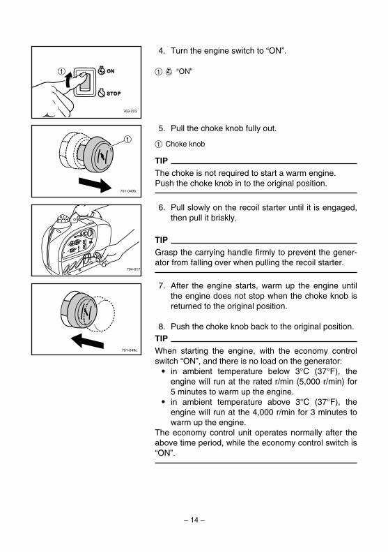
4. Turn the engine switch to “ON”.
1 7 “ON”
763-223
1
5. Pull the choke knob fully out.
1 Choke knob
TIPThe choke is not required to start a warm engine.Push the choke knob in to the original position.
6. Pull slowly on the recoil starter until it is engaged,then pull it briskly.
TIPGrasp the carrying handle firmly to prevent the gener-ator from falling over when pulling the recoil starter.
7. After the engine starts, warm up the engine untilthe engine does not stop when the choke knob isreturned to the original position.
8. Push the choke knob back to the original position.TIPWhen starting the engine, with the economy controlswitch “ON”, and there is no load on the generator:9 in ambient temperature below 3°C (37°F), the
engine will run at the rated r/min (5,000 r/min) for5 minutes to warm up the engine.
9 in ambient temperature above 3°C (37°F), theengine will run at the 4,000 r/min for 3 minutes towarm up the engine.
The economy control unit operates normally after theabove time period, while the economy control switch is“ON”.
701-049c
704-017
701-049b
1
7CG-28199-14 11.3.21 14:56 Page 14
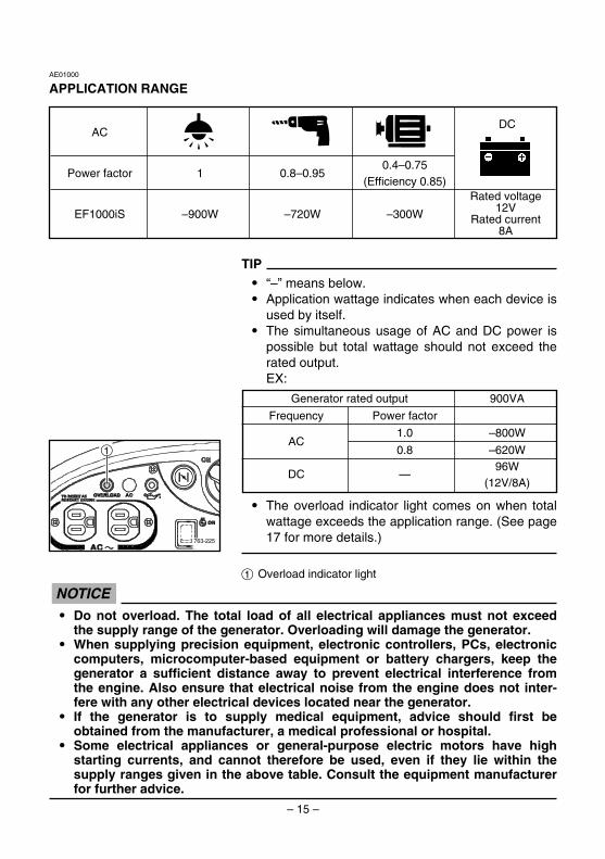
TIP9 “–” means below.9 Application wattage indicates when each device is
used by itself.9 The simultaneous usage of AC and DC power is
possible but total wattage should not exceed therated output.EX:
9 The overload indicator light comes on when totalwattage exceeds the application range. (See page17 for more details.)
1 Overload indicator light
– 15 –
AE01000
APPLICATION RANGE
763-225
1
Generator rated output 900VA
Frequency Power factor
1.0 –800WAC
0.8 –620W96W
DC —(12V/8A)
9 Do not overload. The total load of all electrical appliances must not exceedthe supply range of the generator. Overloading will damage the generator.
9 When supplying precision equipment, electronic controllers, PCs, electroniccomputers, microcomputer-based equipment or battery chargers, keep thegenerator a sufficient distance away to prevent electrical interference fromthe engine. Also ensure that electrical noise from the engine does not inter-fere with any other electrical devices located near the generator.
9 If the generator is to supply medical equipment, advice should first beobtained from the manufacturer, a medical professional or hospital.
9 Some electrical appliances or general-purpose electric motors have highstarting currents, and cannot therefore be used, even if they lie within thesupply ranges given in the above table. Consult the equipment manufacturerfor further advice.
NOTICE
DCAC
Power factor 1 0.8–0.950.4–0.75
(Efficiency 0.85)
EF1000iS –900W –720W –300W
Rated voltage12V
Rated current8A
7CG-28199-14 11.3.21 14:56 Page 15

763-222a
1
– 16 –
763-226
1
761-078a
AE01023
CONNECTIONAlternating Current (AC)
Be sure any electric devices are turned off beforeplugging them in.
9 Be sure all electric devices including the linesand plug connections are in good conditionbefore connection to the generator.
9 Be sure the total load is within generator ratedoutput.
9 Be sure the receptacle load current is withinreceptacle rated current.
1. Start the engine.
2. Plug in to the AC receptacle.
NOTICE
WARNING
3. Make sure the AC pilot light (green) is on.
1 AC pilot light (green)
4. Turn the economy control switch to “ON” and turnon any electric devices.
1 I “ON”
TIPThe economy control switch must be turned to “OFF”when using electric devices that require a large start-ing current, such as a compressor or a submersiblepump.
7CG-28199-14 11.3.21 14:56 Page 16
763-225
1AE00953
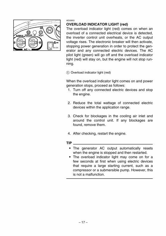
OVERLOAD INDICATOR LIGHT (red)The overload indicator light (red) comes on when anoverload of a connected electrical device is detected,the inverter control unit overheats, or the AC outputvoltage rises. The electronic breaker will then activate,stopping power generation in order to protect the gen-erator and any connected electric devices. The ACpilot light (green) will go off and the overload indicatorlight (red) will stay on, but the engine will not stop run-ning.
1 Overload indicator light (red)
When the overload indicator light comes on and powergeneration stops, proceed as follows:1. Turn off any connected electric devices and stop
the engine.
2. Reduce the total wattage of connected electricdevices within the application range.
3. Check for blockages in the cooling air inlet andaround the control unit. If any blockages arefound, remove them.
4. After checking, restart the engine.
TIP9 The generator AC output automatically resets
when the engine is stopped and then restarted.9 The overload indicator light may come on for a
few seconds at first when using electric devicesthat require a large starting current, such as acompressor or a submersible pump. However, thisis not a malfunction.
– 17 –
7CG-28199-14 11.3.21 14:56 Page 17

AE01100
BATTERY CHARGING
Do not connect a VRLA (Valve Regulated LeadAcid) battery. To charge a VRLA battery, a special(constant-voltage) battery charger is required.
TIP9 The generator DC rated voltage is 12V.9 Start the engine first, and then connect the gener-
ator to the battery for charging.9 Before starting to charge the battery, make sure
that the DC protector is turned on.
1. Start the engine.
NOTICE
2. Press in the DC protector.1 “RESET”2 “OFF”
3. Connect the red battery charger lead to the posi-tive (+) battery terminal.
1 Red wire2 Black wire
4. Connect the black battery charger lead to the neg-ative (–) battery terminal.
5. Turn the economy control switch “OFF” to startbattery charging.
– 18 –
762-040
12
6v 6v 12v762-041
763-238a
1
2
7CG-28199-14 11.3.21 14:56 Page 18

– 19 –
9 Be sure the economy control switch is turned“OFF” while charging the battery.
9 Be sure to connect the red battery chargerlead to the positive (+) battery terminal, andconnect the black lead to the negative (–) bat-tery terminal. Do not reverse these positions.
9 Connect the battery charger leads to the bat-tery terminals securely so that they are notdisconnected due to engine vibration or otherdisturbances.
9 Charge the battery in the correct procedure byfollowing instructions in the owner’s manualfor the battery.
9 The DC protector turns off automatically if cur-rent above the rated flows during batterycharging.To restart charging the battery, turn the DCprotector on by pressing its button to“RESET”. If the DC protector turns off again,stop charging the battery immediately andconsult a Yamaha dealer.
TIP9 Follow instructions in the owner’s manual for the
battery to determine the end of battery charging.9 Measure the specific gravity of electrolyte to deter-
mine if the battery is fully charged. At full charge,the electrolyte specific gravity is between 1.26 and1.28.
9 It is advisable to check the specific gravity of theelectrolyte at least once every hour to preventovercharging the battery.
NOTICE
7CG-28199-14 11.3.21 14:56 Page 19

– 20 –
762-012
9 Electrolyte is poisonous and dangerous sinceit contains sulfuric acid, which causes severeburns. Avoid any contact with skin, eyes orclothing and always shield your eyes whenworking near batteries. In case of contact,administer the following FIRST AID.9 EXTERNAL: Flush with plenty of water.9 INTERNAL: Drink large quantities of water or
milk and immediately call a physician.9 EYES: Flush with water for 15 minutes and
seek prompt medical attention.9 Batteries produce explosive hydrogen gas.
Therefore, keep sparks, flames, cigarettes,etc., away from the battery and provide suffi-cient ventilation when charging it in anenclosed space.
9 KEEP THIS AND ALL BATTERIES OUT OF THEREACH OF CHILDREN.
Operating range of DC power supply (exclusively for charging 12V battery)This power source is designed to charge batteries upto 40Ah that are half-discharged. Do not charge batter-ies of a higher capacity than 40Ah.12V batteryThe time required for recharging a battery variesdepending on the discharge level of the battery. Whenthe specific gravity of the battery reaches 1.26 to 1.28,charging is complete. When charging, check the bat-tery’s specific gravity once an hour.The average time for charging a half-discharged 40Ahbattery is approximately 5 hours. Be sure to check thebattery fluid level before charging.
9 Do not connect any load to the battery or usethe engine starter motor while charging.This causes high current to flow through thegenerator which will burn out the coil.
9 Do not connect a VRLA (Valve Regulated LeadAcid) battery. To charge a VRLA battery, a spe-cial (constant-voltage) battery charger isrequired.
NOTICE
WARNING
7CG-28199-14 11.3.21 14:56 Page 20
– 21 –
763-222
1
761-078
763-223a
1
705-071d
1
ON
OFF
707-097a
AE01025
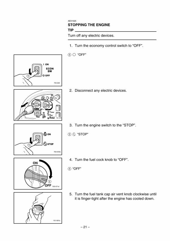
STOPPING THE ENGINETIPTurn off any electric devices.
1. Turn the economy control switch to “OFF”.
1 3 “OFF”
4. Turn the fuel cock knob to “OFF”.
1 “OFF”
5. Turn the fuel tank cap air vent knob clockwise untilit is finger-tight after the engine has cooled down.
3. Turn the engine switch to the “STOP”.
1 5 “STOP”
2. Disconnect any electric devices.
7CG-28199-14 11.3.21 14:56 Page 21
– 22 –
AE00401
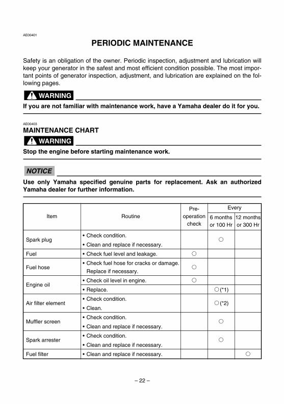
PERIODIC MAINTENANCE
Safety is an obligation of the owner. Periodic inspection, adjustment and lubrication willkeep your generator in the safest and most efficient condition possible. The most impor-tant points of generator inspection, adjustment, and lubrication are explained on the fol-lowing pages.
If you are not familiar with maintenance work, have a Yamaha dealer do it for you.
AE00403
MAINTENANCE CHART
Stop the engine before starting maintenance work.
Use only Yamaha specified genuine parts for replacement. Ask an authorizedYamaha dealer for further information.
NOTICE
WARNING
WARNING
Item RoutinePre-
operationcheck
Every
6 months or 100 Hr
12 monthsor 300 Hr
Spark plug• Check condition.
1• Clean and replace if necessary.
Fuel • Check fuel level and leakage. 1
Fuel hose• Check fuel hose for cracks or damage.
1Replace if necessary.
Engine oil• Check oil level in engine. 1
• Replace. 1(*1)
Air filter element• Check condition.
1(*2)• Clean.
Muffler screen• Check condition.
1• Clean and replace if necessary.
Spark arrester• Check condition.
1• Clean and replace if necessary.
Fuel filter • Clean and replace if necessary. 1
7CG-28199-14 11.3.21 14:56 Page 22

– 23 –
*1····· Initial replacement of the engine oil is after one month or 20 hours of operation.*2·····The air filter element needs to be cleaned more frequently when using in unusually wet or dusty areas.�····· Since these items require special tools, data and technical skills, have a Yamaha dealer perform the ser-
vice.
Item RoutinePre-
operationcheck
Every
6 months or 100 Hr
12 monthsor 300 Hr
Crankcase breather • Check breather hose for cracks or
hosedamage. 1
• Replace if necessary.
Cylinder head• Decarbonize cylinder head.
�• More frequently if necessary.
Valve clearance • Check and adjust when engine is cold. �
Fittings / fasteners• Check all fittings and fasteners.
�• Correct if necessary.
The point where abnormality was recognized by use. 1
7CG-28199-14 11.3.21 14:56 Page 23

– 24 –
760-024
760-0251
4. Check the spark plug type and gap.
a Gap
TIPThe spark plug gap should be measured with a wirethickness gauge and, if necessary, adjusted to specifi-cation.
5. Install the spark plug.
TIPIf a torque wrench is not available when installing aspark plug, a good estimate of the correct torque is1/4-1/2 turn past finger tight. However, the spark plugshould be tightened to the specified torque as soon aspossible.
6. Install the spark plug cap, and then install thecover.
a
760-001a
Standard spark plug:CR4HSB (NGK)
Spark plug gap:0.6–0.7 mm (0.024–0.028 in)
Spark plug torque:13 Nm (1.3 m·kgf, 9.4 ft·lbf)
AE01026
SPARK PLUG INSPECTIONThe spark plug is an important engine component,which should be checked periodically.1. Remove the cover, and then remove the spark
plug cap.
1 Cover
2. Remove the spark plug with a tool.
3. Check for discoloration and remove the carbon.The porcelain insulator around the center elec-trode of spark plug should be a medium-to-lighttan color.
7CG-28199-14 11.3.21 14:56 Page 24

– 25 –
AE00431
CARBURETOR ADJUSTMENTThe carburetor is a vital part of the engine. Adjustingshould be left to a Yamaha dealer with the profession-al knowledge, specialized data, and equipment to doso properly.
3
4
700-124
700-118b
5
AE01159
ENGINE OIL REPLACEMENT
Avoid draining the engine oil immediately afterstopping the engine. The oil is hot and should behandled with care to avoid burns.
1. Place the generator on a level surface and warmup the engine for several minutes.Then stop the engine and turn the fuel cock knobto “OFF”. Turn the fuel tank cap air vent knobclockwise.
WARNING
3. Remove the oil drain joint pushing downward fromthe bottom of the generator and remove the oilfiller cap.
3 Oil drain joint 4 Oil filler cap
788-009
1
2
4. Attach the oil drain joint to the oil filler hole.
5 Oil drain joint
2. Remove the screw and the cover.
1 Screw 2 Cover
7CG-28199-14 11.3.21 14:56 Page 25

– 26 –
7. Add engine oil to the upper level of the filler holeusing the oil filler guide.
6 Oil filler guide
9 Do not tilt the generator when adding engineoil. This could result in overfilling and damageto the engine.
9 Be sure no foreign material enters thecrankcase.
NOTICE700-126a6
700-120
5. Place an oil pan under the engine. Tilt the genera-tor to drain the oil completely.
6. Place the generator on a level surface andremove the oil drain joint.
Recommended engine oil:åYAMALUBE 4 (10W-40),
SAE 10W-30 or 10W-40∫SAE #30çSAE #20∂SAE 10W
Recommended engine oil grade:API Service SE type or higher
Engine oil quantity:0.32 L (0.34 US qt, 0.28 lmp qt)
0°C
å YAMALUBE 4 (10W-40)
∂ SAE 10W ç SAE #20 ∫ SAE #30
32°F
25°C
80°F
8. Wipe the oil drain joint clean, and wipe up anyspilled oil.
9. Install the oil filler cap.
10. Install the oil drain joint in its original position.
11. Install the cover and the screw.
700-117a
788-010
7CG-28199-14 11.3.21 14:56 Page 26

– 27 –
711-068
1
AE01028
MUFFLER SCREEN AND SPARK ARRESTER
The engine and muffler will be very hot after theengine has been run.Avoid touching the engine and muffler while theyare still hot with any part of your body or clothingduring inspection or repair.
1. Remove the cover.
1 Cover
WARNING
741-091
711-069
3
2
2. Remove the muffler screen.
2 Muffler screen3 Bolt
4. Remove the spark arrester.
4 Spark arrester
711-070
3. Use a flathead screw driver to pry the sparkarrester out from the muffler.
711-071
4
7CG-28199-14 11.3.21 14:56 Page 27

– 28 –
5. Remove the carbon deposits on the mufflerscreen and spark arrester using a wire brush.
When cleaning, use the wire brush lightly to avoiddamaging or scratching of the muffler screen andspark arrester.
6. Check the muffler screen and spark arrester.Replace them if damaged.
NOTICE
711-075
711-069a
7. Install the spark arrester.
TIPAlign the spark arrester lump to the hole in the mufflerpipe.
1 Spark arrester lump
2 Hole
8. Install the muffler screen.
711-068a
9. Install the cover.
711-071a21
7CG-28199-14 11.3.21 14:56 Page 28
– 29 –
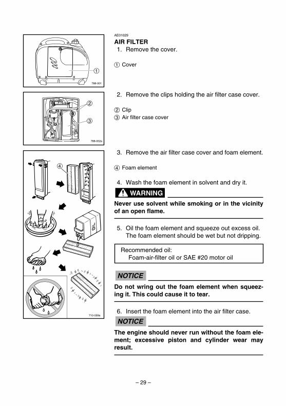
AE01029
AIR FILTER1. Remove the cover.
1 Cover
2. Remove the clips holding the air filter case cover.
2 Clip 3 Air filter case cover
788-001
1
788-002a
3
2
3. Remove the air filter case cover and foam element.
4 Foam element
4. Wash the foam element in solvent and dry it.
Never use solvent while smoking or in the vicinityof an open flame.
5. Oil the foam element and squeeze out excess oil.The foam element should be wet but not dripping.
Do not wring out the foam element when squeez-ing it. This could cause it to tear.
6. Insert the foam element into the air filter case.
The engine should never run without the foam ele-ment; excessive piston and cylinder wear mayresult.
NOTICE
NOTICE
WARNING
710-059a
4
Recommended oil:Foam-air-filter oil or SAE #20 motor oil
7CG-28199-14 11.3.21 14:56 Page 29
– 30 –
707-094
1
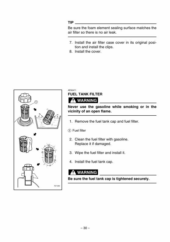
AE00471
FUEL TANK FILTER
Never use the gasoline while smoking or in thevicinity of an open flame.
1. Remove the fuel tank cap and fuel filter.
1 Fuel filter
2. Clean the fuel filter with gasoline.Replace it if damaged.
3. Wipe the fuel filter and install it.
4. Install the fuel tank cap.
Be sure the fuel tank cap is tightened securely.
WARNING
WARNING
TIPBe sure the foam element sealing surface matches theair filter so there is no air leak.
7. Install the air filter case cover in its original posi-tion and install the clips.
8. Install the cover.
7CG-28199-14 11.3.21 14:56 Page 30

– 31 –
707-091
AE01097
TROUBLESHOOTING
Engine won’t start1. Fuel systems
No fuel supplied to combustion chamber.2 No fuel in tank .... Supply fuel.2 Fuel in tank .... Fuel tank cap air vent knob and
fuel cock knob to “ON”.2 Clogged fuel line .... Clean fuel line.2 Clogged carburetor .... Clean carburetor.
705-072
ON
OFF
700-006
763-223b
791-001d
AE00785
Generator won’t produce power2 Safety device (AC) to “OFF” .... Stop the engine,
then restart.2 Safety device (DC protector) to “OFF” .... Press to
“RESET” the DC protector.
2. Engine oil systemInsufficient
2 Oil level is low .... Add engine oil.
3. Electrical systems2 Engine switch to “ON” and pull the recoil starter.
Poor spark2 Spark plug dirty with carbon or wet .... Remove
carbon or wipe spark plug dry.2 Faulty ignition system .... Consult a Yamaha deal-
er.
7CG-28199-14 11.3.21 14:56 Page 31

T Consult a Yamaha dealer.
S Engine does not start.
R OKCleanor
replace
Q
– 32 –
B
P OK
O Clogged
C Does not flicker D Flickers.
AE00515
A ENGINE DOES NOT START
Turn the engine switch to “ON”, then pullthe recoil starter and check if the oilwarning light flickers.
H Pull the recoil starter and check thespark plug for spark strength.(See “WARNING”)
w9 To prevent FIRE HAZARDS be
sure fuel is not present in thespark plug area.
9 To prevent FIRE HAZARDS besure to place the spark plug asfar away as possible from thespark plug hole and carburetorarea.
9 To prevent ELECTRIC SHOCK donot hold spark plug lead withhand while testing.
Dose not sparkJ
Check the following9 Fuel line clogging9 Air cleaner element
clogging.
N
K Check the spark plug.9 Type: CR4HSB9 Gap: 0.6–0.7 mm (0.024–0.028 in)
L Incorrect M OKReplace oradjust gap.
Clean the sparkplug.
E Check engine oil level.
F OK G Level lowConsult aYamaha dealer.
Add engine oil.
OKI
7CG-28199-14 11.3.21 14:56 Page 32

– 33 –
AE00601
STORAGE
Long term storage of your machine will require somepreventive procedures to guard against deterioration.
AE01177
DRAIN THE FUEL1. Turn the engine switch to “STOP”.
1 5 “STOP”
2. Remove the fuel tank cap. Extract the fuel fromthe fuel tank into an approved gasoline containerusing a commercially available handsiphon. Then,install the fuel tank cap.
Fuel is highly flammable and poisonous. Check“SAFETY INFORMATION” (See page 3) carefully.
Immediately wipe off spilled fuel with a clean, dry,soft cloth, since fuel may deteriorate painted sur-faces or plastic parts.
3. Turn the engine switch to “ON”.
1 7 “ON”
4. Turn the fuel cock knob to “ON”.
1 “ON”
5. Start the engine and leave it run until it stops.The engine stops in approximately 20 minutestime by running out of fuel.
TIP9 Do not connect with any electrical devices.
(unloaded operation)9 Duration of the running engine depends on the
amount of the fuel left in the tank.
NOTICE
WARNING
763-223a
1
763-223
1
705-071c
1ON
OFF
704-017
7CG-28199-14 11.3.21 14:56 Page 33
– 34 –
788-001
1
707-103
1
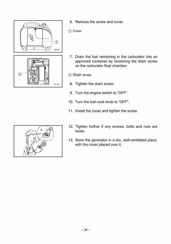
6. Remove the screw and cover.
1 Cover
7. Drain the fuel remaining in the carburetor into anapproved container by loosening the drain screwon the carburetor float chamber.
1 Drain screw
8. Tighten the drain screw.
9. Turn the engine switch to “OFF”.
10. Turn the fuel cock knob to “OFF”.
11. Install the cover and tighten the screw.
12. Tighten further if any screws, bolts and nuts areloose.
13. Store the generator in a dry, well-ventilated place,with the cover placed over it.
7CG-28199-14 11.3.21 14:56 Page 34

– 35 –
712-026
AE00621
ENGINEPerform the following steps to protect the cylinder, pis-ton ring, etc. from corrosion.1. Remove the spark plug, pour about one table-
spoon of SAE 10W-30 or 20W-40 motor oil intothe spark plug hole and reinstall the spark plug.Recoil start the engine by turning over severaltimes (with ignition off) to coat the cylinder wallswith oil.
2. Pull the recoil starter until you feel compression.Then stop pulling. (This prevents the cylinder andvalves from rusting).
3. Clean exterior of the generator and apply a rustinhibitor.
4. Store the generator in a dry, well-ventilated place,with the cover placed over it.
5. The generator must remain in a vertical positionwhen stored, carried or operated.
7CG-28199-14 11.3.21 14:56 Page 35

– 36 –
AE00789
EXHAUST EMISSION CONTROL SYSTEMAND COMPONENTS
Item Acronym9 CARB. ASSY., LH. & JT., .......................CARB (Carburetor)
CARBURETOR29 T.C.I. MAGNETO ASSY. & .....................EI (Electronic Ignition)
PLUG, SPARK9 CRANKCASE1 & HEAD, ........................PCV (Positive Crankcase
CYLINDER1 Ventilation)9 AIR FILTER ASSY. .................................ACL (Air Cleaner)9 MUFF., 2, CAP, NET, WIRE2 &
ARRESTER, SPARK
The above items and the corresponding acronyms are provided in accordancewith U.S. EPA REGULATIONS FOR NEW NONROAD SPARK-IGNITIONNONHANDHELD ENGINES and the CALIFORNIA REGULATIONS FOR 1995AND LATER SMALL OFF-ROAD ENGINES.The acronyms conform to the latest version of the SAE’s recommended prac-tice document J1930, “Diagnostic Acronyms, Terms, and Definitions ForElectrical/Electronic System”.
It is recommended that these items be serviced by a Yamaha dealer.
7CG-28199-14 11.3.21 14:56 Page 36

– 37 –
Unit EF1000iSType Air cooled 4-stroke gasoline OHVCylinder Arrangement Vertical 1 cylinderDisplacement cm3 50Bore × Stroke mm (in) 41.0 × 38.0 (1.61 × 1.50)Operation Hours Hr 4.3–12.0 (rated load–1/4 load)Fuel Unleaded gasolineFuel Tank Capacity L (US gal, Imp gal) 2.5 (0.66, 0.55)Engine Oil Quantity L (US qt, Imp qt) 0.32 (0.34, 0.28)Ignition System TCI
Spark Plug: Type CR4HSB (NGK)Spark Plug: Gap mm (in) 0.6–0.7 (0.024–0.028)
Noise Level*dB / LWA 86
dB (A) / 7 m 48.5–60.5
Unit EF1000iSAC Output
Rated Voltage V 120Rated frequency Hz 60Rated current A 7.5Rated Output VA 900Safety Device: Type Electronic
DC OutputRated voltage V 12Rated current A 8Safety Device: Type DC protector
Unit EF1000iSOverall Length mm (in) 450 (17.7)Overall Width mm (in) 240 (9.4)Overall Height mm (in) 380 (15.0)Dry Weight kg (lb) 12.7 (28.0)
AE00701
SPECIFICATIONSAE00702
DIMENSIONS
AE00704
ENGINE
AE00707
GENERATOR
* : Noise level is measured when the economy control switch is turned to “ON”.LWA shows the sound power level under the ISO3744 satisfied test conditions.The noise level in “dB (A) / 7 m” is the arithmetic mean value in four directions measured 7meters away from each side of the generator. The noise level may vary in different environments.
7CG-28199-14 11.3.21 14:56 Page 37

– 38 –
770-044f
W
W
W
WW
WW
BrBrBr
Br
BrBrBrWWW
BrBrBr
BrBr
WWW
WWW
WWW
R
RR
Br
R
Br
R
W W L L
L
L
L Y B
B
B B B
B
B
B
B
B
R
R
R
RLL
L L
GGYY
O
RL
GY
O
O
B/W
B/WB/W
B/W
B/W
B/WB/W
G/Y
G/Y
B/W
B/W
Y
YY
Y
O
O
1
43
2 5
a
pu
iy
8r
eot
w
q
0
9
776
AE00751
WIRING DIAGRAM
1 Main coil2 Sub coil3 DC coil4 DC rectifier5 Control unit6 AC pilot light7 AC receptacle8 Ground (earth) terminal9 Economy control switch0 Overload indicator lightq DC protector
w DC receptaclee Engine switchr Oil warning lightt Speed limitery Oil level gaugeu Ignition coili Spark plugo TCI unitp TCI magnetoa Stepping motor
Color codeB BlackBr BrownG GreenL BlueO OrangeR RedW WhiteY YellowB/W Black/WhiteG/Y Green/Yellow
7CG-28199-14 11.3.21 14:56 Page 38

– 39 –
YAMAHA MOTOR CORPORATION, U.S.A. EF SERIES GENERATORS
3-YEAR LIMITED WARRANTY
Yamaha Motor Corporation, U.S.A. hereby war-rants that new Yamaha generators purchasedfrom an authorized Yamaha generator dealer inthe United States will be free from defects in mate-rial and workmanship for the period of time statedherein, subject to certain stated limitations.
THE PERIOD OF WARRANTY Any new EF-series Yamaha generator purchased from anauthorized Yamaha generator dealer in the UnitedStates will be warranted against defects in materi-al or workmanship for a period of three (3) yearsfrom date of purchase for pleasure or (exceptEF1000iS) commercial use, subject to exclusionsnoted herein. Yamaha EF1000iS generators pur-chased for commercial use from an authorizedYamaha generator dealer in the continental UnitedStates will be warranted against defects in materi-als or workmanship for a period of two (2) yearsfrom the date of purchase, subject to exclusionsnoted herein.
DURING THE PERIOD OF WARRANTY anyauthorized Yamaha generator service dealer will,free of charge, repair or replace, at Yamaha’soption, any part judged defective by Yamaha dueto faulty workmanship or material from the factory.Parts used in warranty repairs will be warrantedfor the balance of the product’s warranty period.All parts replaced under warranty become theproperty of Yamaha Motor Corporation, U.S.A.
GENERAL EXCLUSIONS from this warranty shallinclude any failures caused by:a. Installation of parts or accessories that are not
qualitatively equivalent to genuine Yamahaparts.
b. Abnormal strain, neglect, or abuse.c. Lack of proper maintenance.d. Accident or collision damage.
SPECIFIC EXCLUSIONS from this warranty shallinclude parts replaced due to normal wear or rou-tine maintenance.
THE CUSTOMER’S RESPONSIBILITY under thiswarranty shall be to:1. Operate and maintain the generator as speci-
fied in the appropriate Owner’s Manual.2. Give notice to an authorized Yamaha con-
sumer generator service dealer of any and allapparent defects within ten (10) days after dis-
covery, and make the machine available atthat time for inspection and repairs at suchdealer’s place of business. You may locateyour nearest authorized Yamaha generatorservice dealer online at www.yamaha-motor.com.
EMISSION CONTROL SYSTEM WARRANTYYamaha Motor Corporation, U.S.A. also warrantsto the ultimate purchaser and each subsequentpurchaser of each 1995 and later YamahaGenerator covered by this warranty that the prod-uct is designed, built, and equipped so as to con-form at the time of sale with all U.S. emissionsstandards applicable at the time of manufactureand that it is free from defects in materials andworkmanship which would cause it not to meetthese standards within the period listed immedi-ately below. Failures other than those resultingfrom defects in material or workmanship whicharise solely as a result of owner abuse and/or lackof proper maintenance are not covered by thiswarranty.All 1995 and Later EF ModelsTwo (2) years from the original purchase date
WARRANTY TRANSFER: To transfer anyremaining warranty from the original purchaser toany subsequent purchaser, it is imperative that theunit be inspected and registered for warranty byan authorized Yamaha consumer generator deal-er. In order for this warranty to remain in effect,this inspection and registration must take placewithin ten (10) days after transfer. A reasonabledealer imposed fee may be charged for theinspection.
YAMAHA MOTOR CORPORATION, U.S.A. MAKESNO OTHER WARRANTY OF ANY KIND,EXPRESSED OR IMPLIED. ALL IMPLIED WAR-RANTIES OF MERCHANTABILITY AND FITNESSFOR A PARTICULAR PURPOSE WHICH EXCEEDTHE OBLIGATIONS AND TIME LIMITS STATED INTHIS WARRANTY ARE HEREBY DISCLAIMED BYYAMAHA MOTOR CORPORATION, U.S.A. ANDEXCLUDED FROM THIS WARRANTY.
SOME STATES DO NOT ALLOW LIMITATIONS ONHOW LONG AN IMPLIED WARRANTY LASTS, SOTHE ABOVE LIMITATIONS MAY NOT APPLY TOYOU. ALSO EXCLUDED FROM THIS WARRANTYARE ANY INCIDENTAL OR CONSEQUENTIAL
7CG-28199-14 11.3.21 14:56 Page 39

– 40 –
DAMAGES INCLUDING LOSS OF USE. SOMESTATES DO NOT ALLOW THE EXCLUSION ORLIMITATION OF INCIDENTAL OR CONSEQUEN-TIAL DAMAGES, SO THE ABOVE EXCLUSIONMAY NOT APPLY TO YOU.
THIS WARRANTY GIVES YOU SPECIFIC LEGALRIGHTS, AND YOU MAY ALSO HAVE OTHERRIGHTS WHICH VARY FROM STATE TO STATE.
YAMAHA MOTOR CORPORATION, U.S.A.Post Office Box 6555
Cypress, California 90630
7CG-28199-14 11.3.21 14:56 Page 40
– 41 –
WARRANTY QUESTIONS AND ANSWERS
Q. Is the warranty transferable to second own-ers?
A. Yes. The remainder of the existing warrantycan be transfered upon request.The unit has to be inspected and reregisteredby an authorized Yamaha generator dealer forthe policy to remain effective.
CUSTOMER SERVICE
If your machine requires warranty service, youmust take it to any authorized Yamaha generatordealer within the continental United States. Besure to bring your warranty registration identifica-tion or other valid proof of the original date of pur-chase. If a question or problem arises regardingwarranty, first contact the owner of the dealership.Since all warranty matters are handled at the deal-er level, this person is in the best position to helpyou. If you are still not satisfied and require addi-tional assistance, please write:
YAMAHA MOTOR CORPORATION U.S.A. CUSTOMER RELATIONS DEPARTMENT
P.O. BOX 6555Cypress, California 90630
CHANGE OF ADDRESS
The federal government requires each manufac-turer to maintain a complete, up-to-date list of allfirst purchasers against the possibility of a safety-related defect and recall. This list is compiled fromthe purchase registrations sent to Yamaha MotorCorporation, U.S.A. by the selling dealer at thetime of your purchase. If you should move afteryou have purchased your new generator, pleaseadvise us of your new address by sending a post-card listing your Yamaha model name, enginenumber, dealer number (or dealer’s name) as it isshown on your warranty identification, your nameand new mailing address. Mail to:
YAMAHA MOTOR CORPORATION, U.S.A.WARRANTY DEPARTMENT
P.O. Box 6555Cypress, California 90630
This will ensure that Yamaha Motor Corporation,U.S.A. has an up-to-date registration record inaccordance with federal law.
Q. What costs are my responsibility during thewarranty period?
A. The customer’s responsibility includes allcosts of normal maintenance service, non-warranty repairs, accident damages, as wellas oil and spark plugs.
Q. What are some examples of “abnormal” strain,neglect, or abuse?
A. These terms are general and overlap eachother in areas. Specific examples include:Running the machine out of oil; lack of propermaintenance; operating the machine with abroken or damaged part which causes anoth-er part to fail; and so on. If you have anyspecific questions on operation or mainte-nance, please contact your dealer for advice.
Q. Does the warranty cover incidental costs suchas transportation due to a failure?
A. No. The warranty is limited to repair of themachine itself.
Q. May I perform any or all of the recommendedmaintenance shown in the Owner’s Manualinstead of having the dealer do them?
A. Yes, if you are a qualified mechanic and followthe procedures specified in the Owner’s andService Manual. We do recommend, however,that items requiring special tools or equipmentbe done by a Yamaha generator dealer.
Q. Will the warranty be void or cancelled if I donot operate or maintain my new Yamahaexactly as specified in the Owner’s Manual?
A. No. The warranty on a new Yamaha cannotbe “voided” or “cancelled.”However, if a particular failure is caused byoperation or maintenance other than asshown in the Owner’s Manual, that failuremay not be covered under warranty.
Q. What responsibility does my dealer haveunder this warranty?
A. Each Yamaha generator dealer is expectedto:1. Check the operation of the generator
before sale.2. Explain the operation, maintenance, and
warranty requirements to your satisfactionat the time of sale, and upon your requestat any later date.
In addition, each Yamaha generator dealer isheld responsible for his setup, service andwarranty repair work.
7CG-28199-14 11.3.21 14:56 Page 41

– 42 –
YAMAHA OUTDOOR POWER EQUIPMENTCALIFORNIA EVAPORATIVE EMISSION CONTROL WARRANTY STATEMENT
YOUR WARRANTY RIGHTS AND OBLIGATIONS
The California Air Resources Board and YamahaMotor Corporation, USA are pleased to explain theevaporative emission control system’s warranty onyour 2006 or later outdoor power equipment. InCalifornia, new equipment that use small off-roadengines must be designed, built, and equipped tomeet the State’s stringent anti-smog standards.Yamaha Motor Corporation, USA must warrant theevaporative emission control system on your out-door power equipment for the period listed belowprovided there has been no abuse, neglect, orimproper maintenance of your equipment.
Your evaporative emission control system mayinclude parts such as: carburetors, fuel tanks, fuellines, fuel caps, valves, canisters, filters, vaporhoses, clamps, connectors, and other associatedcomponents. For engines less than or equal to80cc, only the fuel tank is subject is the evapora-tive emission control warranty requirements of thissection.
MANUFACTURER’SWARRANTY COVERAGE:This evaporative emission control system is war-ranted for two years. If any evaporative emission-related part on your equipment is defective, thepart will be repaired or replaced by Yamaha.
OWNER’SWARRANTY RESPONSIBILITIES:9 As the outdoor power equipment owner, you
are responsible for the performance of therequired maintenance listed in your owner’smanual. Yamaha recommends that you retainall receipts covering maintenance of your out-door power equipment, but Yamaha cannotdeny warranty solely for the lack of receipts.
9 As the outdoor power equipment owner, youshould however be aware that Yamaha maydeny you warranty coverage if your outdoorpower equipment or a part has failed due toabuse, neglect, or improper maintenance, orunapproved modifications.
9 You are responsible for presenting your out-door power equipment to a Yamaha servicecenter as soon as the problem exists. Thewarranty repairs should be completed in areasonable amount of time, not to exceed 30days.
If you have a question regarding your warrantycoverage, you should contact Yamaha CustomerRelations at 1-800-962-7926.
YAMAHA MOTOR CORPORATION, USAPost Office Box 6555
Cypress, California 90630
7CG-28199-14 11.3.21 14:56 Page 42
– 43 –
YAMAHA MOTOR CORPORATION, U.S.A.SMALL OFF ROAD ENGINESCALIFORNIA EMISSION CONTROL WARRANTYYOUR WARRANTY RIGHTS AND OBLIGATIONS
The California Air Resources Board and Yamaha Motor Corporation, U.S.A. are pleased to explain theemission control system warranty on your 2008 and later Small Off Road Engine (SORE). In California,new SORE engines must be designed, built and equipped to meet the State’s stringent anti-smog stan-dards. Yamaha must warrant the emission control system on your SORE engine for the periods of timelisted below provided there has been no abuse, neglect or improper maintenance of your SORE engine.
Your emission control system may include parts such as the carburetor or fuel-injection system, the igni-tion system, and catalytic converter. Also included may be hoses, belts, connectors and other emission-related assemblies.
Where a warrantable condition exists, Yamaha will repair your SORE engine at no cost to you includingdiagnosis, parts and labor.
MANUFACTURER’S WARRANTY COVERAGE
The 2008 and later SORE engines are warranted for two years. If any emissions-related part on yourengine is defective, the part will be repaired or replaced by Yamaha.
OWNER’S WARRANTY RESPONSIBILITIES
9 As the SORE engine owner, you are responsible for the performance of the required maintenancelisted in your owner’s manual. Yamaha recommends that you retain all receipts covering maintenanceon your SORE engine, but Yamaha cannot deny warranty solely for the lack of receipts or for yourfailure to ensure the performance of all scheduled maintenance.
9 As the SORE engine owner, you should however be aware that Yamaha may deny you warranty cov-erage if your SORE engine or a part has failed due to abuse, neglect, improper maintenance or unap-proved modifications.
9 You are responsible for presenting your SORE engine to a Yamaha dealer as soon as a problemexists. The warranty repairs should be completed in a reasonable time, not to exceed 30 days.
If you have any questions regarding your warranty rights and responsibilities, you should contact theYamaha Customer Relations Department at 1-800-962-7926.
Yamaha Motor Corporation, U.S.A. warrants to the ultimate purchaser and each subsequent purchaserthereafter that each new SORE engine certified for sale and registered in California are:
1. Designed, built, and equipped so as to conform, at the time of sale, with all applicable regulationsadopted by the California Air Resources Board, and
2. All warranted parts are free from defects in material and workmanship for the warranty period of theSORE engine or the period prior to the first scheduled replacement point of the warranted part asrequired by the maintenance schedule, if applicable, whichever is less. A defect exists when a defi-ciency in material or workmanship is such that an emission-related warranted part does not functionas designed.
The warranty period begins on the date that the SORE engine is delivered to an ultimate purchaser or onthe date it is first placed in service.
The warranty on emissions-related parts will be interpreted as follows:(1) Any warranted part that is not scheduled for replacement as required maintenance in the written
7CG-28199-14 11.3.21 14:56 Page 43

– 44 –
instructions required by subsection (d) must be warranted for the warranty period defined inSubsection (b)(2). If any such part fails during the period of warranty coverage, it must be repaired orreplaced by the manufacturer according to Subsection (4) below. Any such part repaired or replacedunder the warranty must be warranted for the remaining warranty period.
(2) Any warranted part that is scheduled only for regular inspection in the written instructions required bysubsection (d) must be warranted for the warranty period defined in Subsection (b)(2). A statement insuch written instructions to the effect of “repair or replace as necessary” will not reduce the period ofwarranty coverage. Any such part repaired or replaced under warranty must be warranted for theremaining warranty period.
(3) Any warranted part that is scheduled for replacement as required maintenance in the written instruc-tions required by subsection (d) must be warranted for the period of time prior to the first scheduledreplacement point for that part. If the part fails prior to the first scheduled replacement, the part mustbe repaired or replaced by the engine manufacturer according to Subsection (4) below. Any suchpart repaired or replaced under warranty must be warranted for the remainder of the period prior tothe first scheduled replacement point for the part.
(4) Repair or replacement of any warranted part under the warranty must be performed at no charge tothe owner at a warranty station.
(5) Notwithstanding the provisions of Subsection (4) above, warranty services or repairs must be provid-ed at all manufacturer distribution centers that are franchised to service the subject engines.
(6) The owner must not be charged for diagnostic labor that leads to the determination that a warrantedpart is in fact defective, provided that such diagnostic work is performed at a warranty station.
(7) The manufacturer is liable for damages to other engine components proximately caused by a failureunder warranty of any warranted part.
(8) Throughout the emissions warranty period defined in Subsection (b)(2), the manufacturer must main-tain a supply of warranted parts sufficient to meet the expected demand for such parts.
(9) Any replacement part may be used in the performance of any warranty maintenance or repairs andmust be provided without charge to the owner. Such use will not reduce the warranty obligations ofthe manufacturer.
(10)Add-on or modified parts that are not exempted by the Air Resources Board may not be used. Theuse of any non-exempted add-on or modified parts will be grounds for disallowing a warranty claim.The manufacturer will not be liable to warrant failures of warranted parts caused by the use of a non-exempted add-on or modified part.
(11)The manufacturer issuing the warranty shall provide any documents that describe that manufacturer’swarranty procedures or policies within five working days of request by the Air Resources Board.
WARRANTED PARTS INCLUDE the following:
1. Fuel Metering SystemCarburetor and internal parts (or fuel injection system)Air/fuel ratio feedback and control systemCold start enrichment system
2. Air Induction systemControlled hot air intake systemIntake manifoldAir filter
3. Ignition SystemSpark plugs*Magneto or electronic ignition systemSpark advance/retard system
4. Exhaust Gas Recirculation (EGR) SystemEGR valve body, and carburetor spacer if applicableEGR rate feedback and control system
7CG-28199-14 11.3.21 14:56 Page 44

– 45 –
5. Air Injection SystemAir pump or pulse valveValves affecting distribution of flowDistribution manifold
6. Catalyst or Thermal Reactor SystemCatalytic converterThermal reactorExhaust manifold
7. Particulate ControlsTraps, filters, precipitators, and any other deviceused to capture particulate emissions
8. Miscellaneous Items Used in Above SystemsVacuum, temperature, and time sensitivevalves and switchesElectronic controlsHoses, belts, connectors, and assemblies
9. Engine components damaged due to a failure under warranty or a warranted part
*The original spark plug(s) are warranted for the period of replacement indicated in the Owner’s Manualand not the useful life of the SORE engine (see your Owner’s Manual).
DURING THE PERIOD OF THIS WARRANTY
Yamaha Motor Corporation, U.S.A. will repair or replace any warranted part deemed defective by Yamahaduring the scope of the warranty without charge to the owner, including parts, labor, and diagnosis. Thiswork must be done at an authorized Yamaha dealer. Give notice to an authorized Yamaha dealer of anyapparent defects(s) within a reasonable period of time after discovery. The SORE engine must be madeavailable for inspection by an authorized Yamaha dealer.
OWNER’S RESPONSIBILITY:
The owner of the SORE engine is responsible for the performance of required maintenance (see yourOwner’s Manual). Receipts and maintenance records covering the performance of regular maintenanceshould be retained in the event questions arise concerning maintenance. The receipts should be trans-ferred to each subsequent owner of this SORE engine.
The emission control systems of your Yamaha SORE engine were designed, built, tested, and certified asbeing in conformity with California emission control regulations using genuine Yamaha parts. Accordingly,it is recommended that any replacement part(s) used for maintenance, replacement, or repair of emissioncontrol systems be Yamaha parts. The owner may elect to have maintenance, replacement, or repair ofthe emission control devices and systems performed by any repair establishment or individual, and mayelect to use parts other than Yamaha parts for such maintenance, replacement, or repair without invalidat-ing this warranty. However, the cost of such service or parts will not be covered under the warranty.
EXCLUSIONS: No warranty coverage will be allowed if the part(s) failure was caused by owner/operatorabuse, neglect, tampering, improper adjustment unless performed by a dealer during warranty repairwork, modification, misuse, alteration, or improper maintenance (see your Owner’s Manual).
Use of parts which are not qualitatively equivalent to genuine Yamaha parts, improper service, or lack ofrequired maintenance which causes failure of a warranted part may constitute abuse and/or improper ser-vice, thereby invalidating warranty liability hereunder.
7CG-28199-14 11.3.21 14:56 Page 45

– 46 –
This warranty does not cover damage resulting from accidents, acts of nature, or other events or occur-rences beyond the control of Yamaha. Yamaha Motor Corporation, U.S.A. expressly disclaims responsi-bility for any and all consequential damages, such as loss of time, inconvenience, loss or use of theSORE engine, or commercial loss.
YAMAHA MOTOR CORPORATION, U.S.A.Post Office Box 6555
Cypress, California 90630
7CG-28199-14 11.3.21 14:56 Page 46
– 47 –
YAMAHA EXTENDED SERVICE (Y.E.S.)
Keep your Yamaha Generator protected even after your warranty expires with genuine Yamaha ExtendedService (Y.E.S.).
9 Y.E.S. is designed and administered by Yamaha Motor Corporation to provide maximum owner satis-faction. You get uninterrupted factory-backed coverage for extra peace of mind.
9 Y.E.S. is flexible. You can choose the plan that’s right for you: 12 months, 24 months or 36 monthscoverage.
9 Y.E.S. is administered by the same Yamaha people that handle your warranty - and it shows in thecomprehensive coverage benefits. There are no hour limitations and Y.E.S. covers manufacturingdefects just like your warranty. See a sample contract at your Yamaha dealer and see how comfort-ing uninterrupted factory backed protection can be.
9 There are no “out-of-pocket” expenses for covered repairs. Yamaha will never ask you to pay adeductible.
9 Nationwide coverage. Y.E.S. coverage is honored at any authorized Yamaha Outdoor PowerEquipment Service dealer.
9 Y.E.S. coverage is transferable to a new owner if you sell or trade-in. That can make you Yamahamuch more valuable.
This excellent Y.E.S. plan coverage is only available to Yamaha owners like you, and only while yourYamaha is still within the Yamaha Limited Warranty period. So visit your authorized Yamaha dealer toget all the facts. He can show you how easy it is to protect your investment with Yamaha ExtendedService.
Special note:If visiting your dealer isn’t convenient, contact Yamaha with your Primary ID number (your frame number).We’ll be happy to help you get the Y.E.S. coverage you need.
Yamaha Service MarketingP.O. Box 6555
Cypress, CA 906301-866-YES-EXTD(1-866-937-3983)
7CG-28199-14 11.3.21 14:56 Page 47

— MEMO —
7CG-28199-14 11.3.21 14:56 Page 48

— MEMO —
7CG-28199-14 11.3.21 14:56 Page 49

Read this manual carefully before operating this machine. This manualshould stay with this machine if it is sold.
7CG-28199-14_hyoshi 11.4.18 10:14 Page 2

Generator
LIT-19626-01-677CG-28199-14PRINTED ON RECYCLED PAPER
PRINTED IN JAPAN2011.04-0.5×1 !
(E)
EF1000iS
OWNER’S MANUAL
Read this manual carefully before operating this machine.
7CG-28199-14_hyoshi 11.4.18 10:14 Page 1

To b
egin
yo
ur
3 ye
ar w
arra
nty
cov
erag
e, p
leas
e re
gis
ter
on
line
wit
hin
30
day
s o
f p
urc
has
e:w
ww
.yam
ahaw
arra
nty
reg
istr
atio
n.c
om
If yo
u pr
efer
, you
can
com
plet
e an
d m
ail t
his
card
. Be
sure
to a
ttach
pro
per
post
age.
Ow
ner’s
Nam
e
Add
ress
City
S
tate
Zip
Pho
ne N
umbe
r (
)
-
E-m
ail a
ddre
ss
Yam
aha
Gen
erat
or M
odel
Nam
e:
Yam
aha
Gen
erat
or P
rimar
y I.D
. Ser
ial N
umbe
r:(S
ee “
Mac
hine
Iden
tifica
tion”
in y
our
Ow
ner’s
Man
ual f
or lo
catio
n of
this
num
ber)
(The
eng
ine
stam
p is
not
the
valid
Prim
ary
ID S
eria
l Num
ber)
-
(Exa
mpl
e) E
F20
00IS
(Exa
mpl
e) 7
DK
- 0
0000
00
Dat
e P
urch
ased
/
/
S
ellin
g D
eale
r N
ame
Mon
th
D
ay
Yea
r
9 P
leas
e re
gist
er o
nlin
e or
com
plet
e an
d m
ail t
his
form
. It
will
hel
p en
sure
that
Yam
aha
has
accu
rate
ly r
egis
tere
d yo
ur p
urch
ase
for
war
rant
y.9 M
anuf
actu
rers
are
req
uire
d to
mai
ntai
n a
com
plet
e up
-to-
date
list
of a
ll fir
st p
urch
aser
s of
pro
duct
s in
the
even
t of a
saf
ety-
rela
ted
defe
ct o
r re
call.
REG
ISTE
R O
NLI
NE
OR
MAI
L TH
IS C
ARD
TO
YAM
AHA
MO
TOR
CO
RPO
RAT
ION
, U.S
.A.
Gen
erat
or W
arra
nty
Reg
istr
atio
n
Reg
iste
r You
r Gen
erat
or a
t
ww
w.y
amah
awar
rant
yreg
istr
atio
n.co
mO
r co
mpl
ete
the
card
bel
ow a
nd M
ail
PLACESTAM
PHERE
YAM
AH
A M
OTO
R C
OR
PO
RA
TIO
N U
.S.A
.P.O
. BO
X 6555
CY
PR
ES
S, C
A 90630
AT
TN
: WA
RR
AN
TY
DE
PAR
TM
EN
T


![sistemasumma.files.wordpress.com · g _X? ^GZ cKkZ [AB g M p w I M f p 7 ¡ O ~¢ @7CG?A c_kKdEkX N | ?ACFCG Ix]£^8¤,BI^OEGBIKMEO?¥[A`\BDCGN PkZ vON§¦¨Z\Hb`©](https://static.fdocuments.us/doc/165x107/5e8097b9d51dd71cfa744750/g-x-gz-ckkz-ab-g-m-p-w-i-m-f-p-7-o-7cga-ckkdekx-n-acfcg-ix8bioegbikmeoabdcgn.jpg)