OWNER INSTRUCTIONS, DO NOT DESTROY NOTE: … JT Installation Manual.pdf · DO NOT DESTROY. PLEASE...
15
Copyright © 1998, Tjernlund Products, Inc. All rights reserved. P/N 8504034 REV. 11/97 OWNER INSTRUCTIONS, DO NOT DESTROY Recognize this symbol as an indication of important Safety Information! NOTE: FLUE GAS TEMPERATURES MUST NOT EXCEED 600 o F AT VENT SYSTEM INLET. THESE INSTRUCTIONS ARE INTENDED AS AN AID TO QUALIFIED, LICENSED SERVICE PERSONNEL FOR PROPER INSTALLATION, ADJUSTMENT AND OPERATION OF THIS UNIT. READ THESE INSTRUCTIONS THOROUGHLY BEFORE ATTEMPTING INSTALLATION OR OPERATION. FAILURE TO FOLLOW THESE INSTRUCTIONS MAY RESULT IN IMPROPER INSTALLATION, ADJUST- MENT, SERVICE OR MAINTENANCE POSSIBLY RESULTING IN FIRE, ELECTRI- CAL SHOCK, CARBON MONOXIDE POISONING, EXPLOSION, OR PERSONAL INJURY OR PROPERTY DAMAGE. ! DO NOT DESTROY. PLEASE READ CAREFULLY AND KEEP IN A SAFE PLACE ON JOB SITE FOR FUTURE REFERENCE. MODELS DESCRIPTION *GPAK-JT* FOR GAS APPLIANCES WITH A BTU/HR INPUT OF 120,000 OR LESS WHICH REQUIRE A POWER VENTER POST PURGE *GPAK-1T* FOR GAS APPLIANCES WITH A BTU/HR INPUT FROM 100,000 TO 250,000 WHICH REQUIRE A POWER VENTER POST PURGE NOTE: THE *GPAK* MODELS INCLUDE A 4” DRAFT CONTROL AND ARE AUTHORIZED FOR USE ON FURNACES ELIGIBLE FOR THE HTPV CORRECTIVE ACTION PROGRAM. INSTALLATIONS FOR THE HTPV CORRECTIVE ACTION PROGRAM MUST USE TYPE “B” VENT. TJERNLUND PRODUCTS, INC. 1601 Ninth Street • White Bear Lake, MN 55110-6794 PHONE (800) 255-4208 • (651) 426-2993 • FAX (651) 426-9547 Visit our web site • www.tjernlund.com
Transcript of OWNER INSTRUCTIONS, DO NOT DESTROY NOTE: … JT Installation Manual.pdf · DO NOT DESTROY. PLEASE...

Copyright © 1998, Tjernlund Products, Inc. All rights reserved. P/N 8504034
REV. 11/97
OWNER INSTRUCTIONS, DO NOT DESTROY
Recognize this symbol as an indication of important Safety Information!
NOTE: FLUE GAS TEMPERATURES MUST NOT EXCEED
600oF AT VENT SYSTEM INLET.
THESE INSTRUCTIONS ARE INTENDED AS AN AID TO QUALIFIED, LICENSEDSERVICE PERSONNEL FOR PROPER INSTALLATION, ADJUSTMENT ANDOPERATION OF THIS UNIT. READ THESE INSTRUCTIONS THOROUGHLYBEFORE ATTEMPTING INSTALLATION OR OPERATION. FAILURE TO FOLLOWTHESE INSTRUCTIONS MAY RESULT IN IMPROPER INSTALLATION, ADJUST-MENT, SERVICE OR MAINTENANCE POSSIBLY RESULTING IN FIRE, ELECTRI-CAL SHOCK, CARBON MONOXIDE POISONING, EXPLOSION, OR PERSONALINJURY OR PROPERTY DAMAGE.
!
DO NOT DESTROY. PLEASE READ CAREFULLY AND KEEPIN A SAFE PLACE ON JOB SITE FOR FUTURE REFERENCE.
MODELS DESCRIPTION
*GPAK-JT* FOR GAS APPLIANCES WITH A BTU/HR INPUT OF 120,000 OR LESS WHICH REQUIRE A POWER VENTER POST PURGE
*GPAK-1T* FOR GAS APPLIANCES WITH A BTU/HR INPUT FROM 100,000 TO 250,000 WHICH REQUIRE A POWER VENTER POST PURGE
NOTE: THE *GPAK* MODELS INCLUDE A 4” DRAFT CONTROL AND ARE AUTHORIZED FOR USE ON FURNACES ELIGIBLE FOR THE HTPV CORRECTIVE ACTION PROGRAM. INSTALLATIONS FOR THE HTPV CORRECTIVE ACTION PROGRAM MUST USE TYPE “B” VENT.
TJERNLUND PRODUCTS, INC.1601 Ninth Street • White Bear Lake, MN 55110-6794PHONE (800) 255-4208 • (651) 426-2993 • FAX (651) 426-9547Visit our web site • www.tjernlund.com

TABLE OF CONTENTS
PAGE(S)GPAK DESCRIPTION .................................................................................................................................................. 1GPAK SIZING ................................................................................................................................................................ 1SPECIFICATIONS ......................................................................................................................................................... 2INSTALLATION RESTRICTIONS .............................................................................................................................. 2-3INSTALLER NOTES...................................................................................................................................................... 3SAFETY INSPECTION OF EXISTING APPLIANCE INSTALLATION .......................................................................... 4VENT HOOD LOCATION & INSTALLATION ............................................................................................................. 4-5POWER VENTER INSTALLATION ............................................................................................................................ 5-7ELECTRICAL WIRING ................................................................................................................................................7-9
INSTALLATION RESTRICTIONS ................................................................................................................... 7SEQUENCE OF OPERATION ........................................................................................................................ 7WIRING TO GAS VALVE ................................................................................................................................ 8ALTERNATIVE WIRING WITH THERMOSTAT .............................................................................................. 9
OPERATION CIRCUIT CHECK .................................................................................................................................... 9SAFETY INTERLOCK/COMBUSTION AIR TEST .......................................................................................................10AIR FLOW ADJUSTMENT .......................................................................................................................................... 10TROUBLESHOOTING .......................................................................................................................................... 10 -12MAINTENANCE .......................................................................................................................................................... 12HOW TO OBTAIN SERVICE & LIMITED WARRANTY ......................................................................................... 12-13PERFORMANCE CURVES ........................................................................................................................................ 13VH1-4 VENT HOOD MOUNTING TEMPLATE ........................................................................................................... 14
Tjernlund Products welcomes your comments and questions. Call us at 1-800-255-4208, Fax 612-426-9547 or write to:Customer Service, Tjernlund Products, Inc., 1601 Ninth Street, White Bear Lake, MN 55110-6794.
GPAK DESCRIPTION
The *GPAK* Series is a complete venting system designed to Side Wall Vent Natural and LP gas heating appliances. Each *GPAK*comes with three major components: A Power Venter, Vent Hood and DC-4” Draft Control. The GPAK-JT can handle a maximumBTU/HR input of 120,000. The GPAK-1T can handle BTU/HR inputs from 100,000 to 250,000. The “T” of the GPAK-JT indicatesthese kits have a post purge Relay/Timer which allows the Power Venter to continue operating for a non-adjustable period of approxi-mately 45 seconds after the appliance burner shuts off.
GPAK SIZING
Verify that the GPAK you are about to install is properly sized for the appliance.
1. If installing the GPAK-JT, confirm that the BTU/HR. input of the appliance is 120,000 or less. If installing the GPAK-1T, confirm that the BTU/HR. input of the appliance is between 100,000 and 250,000.
2. Determine that the equivalent vent pipe length to be installed is within the appropriate GPAK’s performance. An example of calcu-lating the equivalent vent pipe length is shown on page 2.
NOTES1. If the appliance flue outlet is greater than 4”, install a
tapered reducer directly after the draft hood, draft diverter or barometric draft control, reducing vent pipe diameter to 4”. All vent pipe from the appliance to the Power Venter may be 4”.
2. Table is based on straight vent pipe. 90 degree elbows are equivalent to 6 feet of straight vent pipe, 45 degree elbows are equivalent to 3 feet of straight vent pipe. An example of calculating equivalent pipe length is on top of page 2.
3. Determine maximum pipe length from type of equip-ment being vented and GPAK Model. Category A pipe runs over 30 linear feet should use Type “B” vent. Category B & C pipe runs over 15 linear feet should use Type “B” vent. Installations for the HTPV Corrective Action Program must use Type “B” vent.
4. Column C allows for up to a 40,000 BTU/hr. Input atmospheric water heater common vented with a fan assisted appliance from column B.
5. All reducers and vent pipe are to be supplied by the installer and are available from your local heating wholesaler.
1
MODEL SELECTION TABLE
*GPAK-JT*
*GPAK-1T*
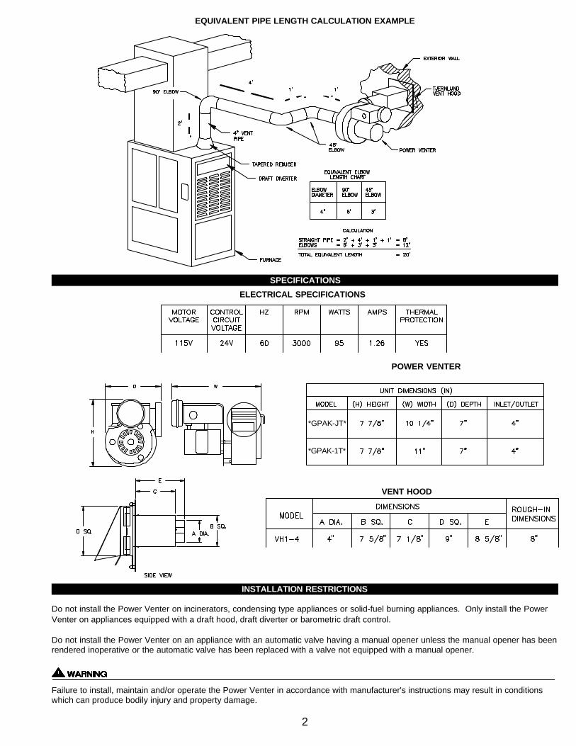
EQUIVALENT PIPE LENGTH CALCULATION EXAMPLE
SPECIFICATIONS
INSTALLATION
INSTALLATION RESTRICTIONS
Do not install the Power Venter on incinerators, condensing type appliances or solid-fuel burning appliances. Only install the PowerVenter on appliances equipped with a draft hood, draft diverter or barometric draft control.
Do not install the Power Venter on an appliance with an automatic valve having a manual opener unless the manual opener has beenrendered inoperative or the automatic valve has been replaced with a valve not equipped with a manual opener.
Failure to install, maintain and/or operate the Power Venter in accordance with manufacturer's instructions may result in conditionswhich can produce bodily injury and property damage.
2
ELECTRICAL SPECIFICATIONS
VENT HOOD
POWER VENTER
*GPAK-JT*
*GPAK-1T*
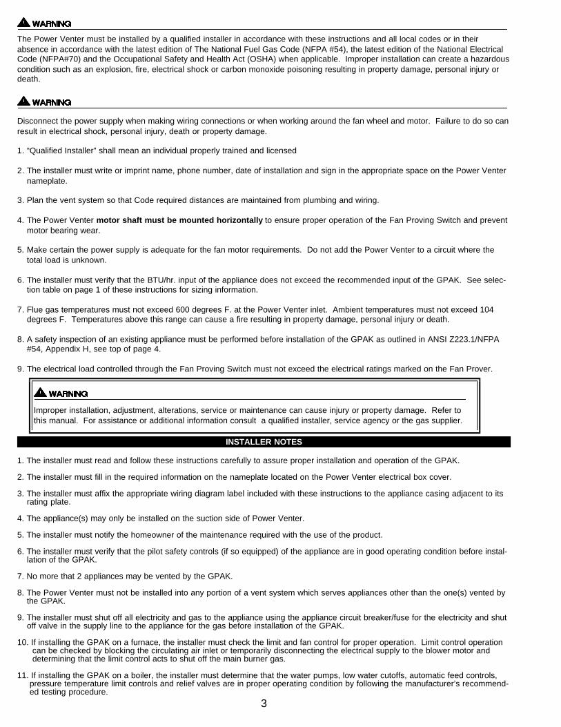
The Power Venter must be installed by a qualified installer in accordance with these instructions and all local codes or in theirabsence in accordance with the latest edition of The National Fuel Gas Code (NFPA #54), the latest edition of the National ElectricalCode (NFPA#70) and the Occupational Safety and Health Act (OSHA) when applicable. Improper installation can create a hazardouscondition such as an explosion, fire, electrical shock or carbon monoxide poisoning resulting in property damage, personal injury ordeath.
Disconnect the power supply when making wiring connections or when working around the fan wheel and motor. Failure to do so canresult in electrical shock, personal injury, death or property damage.
1. “Qualified Installer” shall mean an individual properly trained and licensed
2. The installer must write or imprint name, phone number, date of installation and sign in the appropriate space on the Power Venter nameplate.
3. Plan the vent system so that Code required distances are maintained from plumbing and wiring.
4. The Power Venter motor shaft must be mounted horizontally to ensure proper operation of the Fan Proving Switch and prevent motor bearing wear.
5. Make certain the power supply is adequate for the fan motor requirements. Do not add the Power Venter to a circuit where the total load is unknown.
6. The installer must verify that the BTU/hr. input of the appliance does not exceed the recommended input of the GPAK. See selec-tion table on page 1 of these instructions for sizing information.
7. Flue gas temperatures must not exceed 600 degrees F. at the Power Venter inlet. Ambient temperatures must not exceed 104 degrees F. Temperatures above this range can cause a fire resulting in property damage, personal injury or death.
8. A safety inspection of an existing appliance must be performed before installation of the GPAK as outlined in ANSI Z223.1/NFPA #54, Appendix H, see top of page 4.
9. The electrical load controlled through the Fan Proving Switch must not exceed the electrical ratings marked on the Fan Prover.
INSTALLER NOTES
1. The installer must read and follow these instructions carefully to assure proper installation and operation of the GPAK.
2. The installer must fill in the required information on the nameplate located on the Power Venter electrical box cover.
3. The installer must affix the appropriate wiring diagram label included with these instructions to the appliance casing adjacent to its rating plate.
4. The appliance(s) may only be installed on the suction side of Power Venter.
5. The installer must notify the homeowner of the maintenance required with the use of the product.
6. The installer must verify that the pilot safety controls (if so equipped) of the appliance are in good operating condition before instal-lation of the GPAK.
7. No more that 2 appliances may be vented by the GPAK.
8. The Power Venter must not be installed into any portion of a vent system which serves appliances other than the one(s) vented by the GPAK.
9. The installer must shut off all electricity and gas to the appliance using the appliance circuit breaker/fuse for the electricity and shut off valve in the supply line to the appliance for the gas before installation of the GPAK.
10. If installing the GPAK on a furnace, the installer must check the limit and fan control for proper operation. Limit control operation can be checked by blocking the circulating air inlet or temporarily disconnecting the electrical supply to the blower motor anddetermining that the limit control acts to shut off the main burner gas.
11. If installing the GPAK on a boiler, the installer must determine that the water pumps, low water cutoffs, automatic feed controls, pressure temperature limit controls and relief valves are in proper operating condition by following the manufacturer’s recommend-ed testing procedure.
3
Improper installation, adjustment, alterations, service or maintenance can cause injury or property damage. Refer tothis manual. For assistance or additional information consult a qualified installer, service agency or the gas supplier.

*SAFETY INSPECTION OF A PREVIOUSLY USED GAS APPLIANCE(Perform prior to GPAK installation)
The following procedure is intended as a guide to aid in determining that an appliance is properly installed and is in safe condition forcontinuing use.
The following procedure is based on central furnace and boiler installations and it should be recognized that generalized procedurescannot anticipate all situations. Accordingly, in some cases deviation from this procedure may be necessary to determine safe opera-tion of the equipment.
a. Perform this procedure prior to any attempt at modifications of the appliance or installation of the GPAK.b. If it is determined there is a condition which could result in unsafe operation, shut off the appliance and advise the owner of the
unsafe condition.
Follow the steps below in making the safety inspection:
1. Conduct a gas leakage test of the appliance piping and control system downstream of the shutoff valve in the supply line to the appliance.
2. Visually inspect the venting system and determine there is no blockage or restriction, leakage, corrosion and other deficiencies which could cause an unsafe condition.
3. Shut off all gas to the appliance(s).4. Inspect burners and crossovers for blockage and corrosion.5. Applicable only to furnaces: Inspect heat exchanger for cracks, openings or excessive corrosion. Check both the limit control
and fan control for proper operation.6. Applicable only to boilers: Inspect for evidence of water or combustion product leaks. Determine that the water pumps are in
operating condition. Test low water cutoffs, automatic feed controls, pressure and temperature limit controls and relief valves in accordance with the manufacturer's recommendations to determine that they are in operating order.
* Excerpts from the National Fuel Gas Code (ANSI Z223.1/NFPA #54), Appendix H.
VENT HOOD LOCATION
If possible, locate the Vent Hood on a wall that does not face the direction of prevailing winds. This will diminish the possibility ofappliance interruption during periods of extreme winds.
If possible, locate the Vent Hood no closer than 3 feet from an inside corner of an L-shaped structure.
CODE REQUIREMENTS
Terminate the vent system so that proper minimum clearances are maintained as cited in the latest edition of the National Fuel GasCode (NFPA # 54) and the latest edition of NFPA #211, or as follows:
• Not be less than 7 feet above grade when located adjacent to public walk ways.• At least 3 feet above any forced air inlet located within 10 feet.• At least 4 feet below, 4 feet horizontally from or 1 foot above any door, window or gravity air inlet into any building. • At least 12 inches above grade.• So that the flue gases are not directed so as to jeopardize people, overheat combustible structures or enter buildings, and• Not less than 2 feet from an adjacent building.
4

VENT HOOD INSTALLATION
1. Attach the template on page 14 to the interior of the wall the vent hood will be penetrating.
2. Verify that wall penetration will not come in contact with concealed wiring or plumbing. Using a 1/2” drill bit, drill two pilot holes where noted on the template. The drill bit must be long enough to penetrate to the building exterior.
3. Attach the template to the building exterior aligning the pilot holes on the template with the pilot holes drilled in step 2.
4. Using a reciprocating saw, cut an opening through the building siding, wall board, etc., following the appropriate lines of the template.
5. Slide the Vent Hood through the opening and fasten to exterior wall using provided screws.
6. Once Power Venter is completely installed and secured, apply a bead of exterior rated caulk between Vent Hood flange and exteri-or of building.
POWER VENTER INSTALLATION
CODE REQUIREMENTS
The Power Venter installation must be done in accordance with the following requirements of the latest Edition of the National FuelGas Code (NFPA #54):
• All portions of the vent system under positive pressure during operation (on the outlet side of Power Venter) shall be designed and installed so as to prevent leakage of flue or vent gases into the building,
• All appliances must enter the vent system on the inlet side of the Power Venter,
• Provision shall be made to interlock the appliance(s) to prevent the flow of gas to the main burners when the draft system is not performing so as to satisfy the operating requirements of the equipment for safe performance. See “Electrical Wiring” section of this manual for details.
INSTALLER NOTES
1. All vent pipe and reducers must be supplied by the installer and are available from your heating wholesaler.
2. To prevent motor bearing wear and to ensure proper Fan Proving Switch operation, the Power Venter must be mounted with shaft of the motor horizontal, (See Diagram A).
3. If the appliance flue is greater than 4 inch, install a taperedreducer on the appliance and run 4 inch vent pipe from the appliance to the Power Venter, (See Diagram B).
4. The Power Venter housing is single wall, a 6 inch clearance to combustible materials must be maintained, (See Diagram C).
5
DIAGRAM A
DIAGRAM B
DIAGRAM C
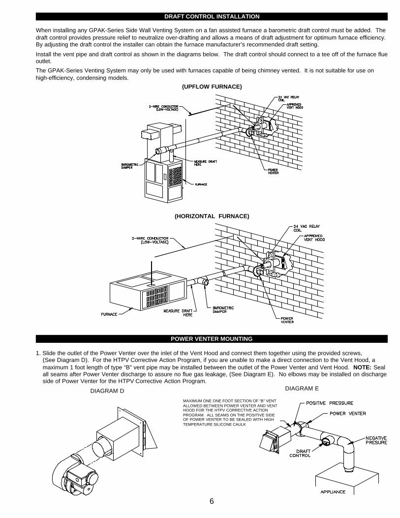
DRAFT CONTROL INSTALLATION
When installing any GPAK-Series Side Wall Venting System on a fan assisted furnace a barometric draft control must be added. Thedraft control provides pressure relief to neutralize over-drafting and allows a means of draft adjustment for optimum furnace efficiency.By adjusting the draft control the installer can obtain the furnace manufacturer’s recommended draft setting.
Install the vent pipe and draft control as shown in the diagrams below. The draft control should connect to a tee off of the furnace flueoutlet.
The GPAK-Series Venting System may only be used with furnaces capable of being chimney vented. It is not suitable for use onhigh-efficiency, condensing models.
POWER VENTER MOUNTING
1. Slide the outlet of the Power Venter over the inlet of the Vent Hood and connect them together using the provided screws,(See Diagram D). For the HTPV Corrective Action Program, if you are unable to make a direct connection to the Vent Hood, a maximum 1 foot length of type “B” vent pipe may be installed between the outlet of the Power Venter and Vent Hood. NOTE: Seal all seams after Power Venter discharge to assure no flue gas leakage, (See Diagram E). No elbows may be installed on dischargeside of Power Venter for the HTPV Corrective Action Program.
6
DIAGRAM D DIAGRAM E
(HORIZONTAL FURNACE)
(UPFLOW FURNACE)
MAXIMUM ONE ONE FOOT SECTION OF “B” VENTALLOWED BETWEEN POWER VENTER AND VENTHOOD FOR THE HTPV CORRECTIVE ACTIONPROGRAM. ALL SEAMS ON THE POSITIVE SIDEOF POWER VENTER TO BE SEALED WITH HIGHTEMPERATURE SILICONE CAULK

2. To facilitate installation and reduce vibration we have included 2 mounting brackets, 2 rubber isolaters and 2 rubber grommets. One of the brackets may be used temporarily as a third hand while positioning it for permanentinstallation.
3. When installing the Power Venter for horizontal mount, install one of the brackets to the electrical box using the nut/screw provided. Install the other to the damper rod as shown to the right. When installing the Power Venter for vertical mount, only one bracket is needed. This bracket should be mounted to the motor as shown to the right. Temporarily support the Power Venter using wire or a ladder and assemble the mount-ing brackets, (See Diagram F).
4. Install plumbers strap from the Power Venter to the floor joist, (See Diagram F).
5. Install 4 inch vent pipe from the Power Venter inlet to the appliance flue outlet avoiding elbows when possible.
ELECTRICAL WIRING
INSTALLATION RESTRICTIONS
1.The installer must ensure that all electrical connections between the appliance and Power Venter are tight and that all wires are positioned and secured so they cannot come in contact with high temperature locations. Use adequate conduit supports where necessary.
2. The installer must ensure that the internal appliance transformer is rated no lower than 40VA..3. The installer must ensure that the heat anticipator in the comfort thermostat is adjusted according to the thermostat manufacturers
recommendation.4. All wiring From the Power Venter to the appliance must be appropriate Class 1 wiring as follows: installed in rigid metal conduit,
intermediate metal conduit, rigid non-metallic conduit, electrical metallic tubing Type MI, Type MC Cable, or otherwise be suitably protected from physical damage.
5. The Fan Proving Switch is not suitable for loads which exceed the limitations below. The electrical contact ratings for the Fan Proving Switch are as follows:
3 AMPS (full load) at 120VAC; 28VA Pilot Duty (1.16 Amps) at 24VAC; 125VA Pilot Duty at 120VAC
6. All 24V wiring must be at least 18 AWG. All 115V wiring must be at least 14 AWG.7. All wiring must be in compliance with local codes or in their absence, with the latest Edition of the National Electric Code (NFPA #70).8. Disconnect 115V power before attempting to wire the Power Venter to the appliance. Power may be disconnected by means of
the appliance circuit breaker/fuse.
*GPAK-JT* / *GPAK-1T* SEQUENCE OF OPERATION WIRED TO GAS VALVE:As the thermostat/aquastat senses a need for heat, the internal switch of the thermostat/aquastat will close. The Switch closure com-pletes the 24V electrical circuit to the internal controls of the appliance. Before the 24V signal reaches the appliance gas valve, it isinterrupted by the Power Venter Relay/Timer and Fan Proving Switch. When the Power Venter Relay/Timer receives the 24V signal,the contact side closes completing the 115V circuit to the Power Venter motor. The air movement generated by the Power Ventercloses the Fan Proving Switch and completes the circuit to the appliance gas valve. The appliance gas valve will only receive powerwhen the appliance thermostat/aquastat is calling for heat and the Power Venter is operating. When the appliance thermostat/aquas-tat is satisfied, 24V will be discontinued to the Relay/Timer and the Power Venter will continue to operate for a non-adjustable postpurge period of approximately 45 seconds.
NOTES: While it is impossible to include every possible wiring scenario, the following diagrams represent the most common. If wiring theGPAK to an appliance not equipped with the controls shown on the following diagrams, determine which terminals of the gas valveare considered “HOT” and “COMMON” and follow the steps on the bottom of page 8 for the GPAK-JT/GPAK-1T.
When wiring Power Venter to the gas valve wire all thermostats, zones, circulators and limits as would normally be done if venting intoa chimney.NAT
If you are unable to wire the GPAK as outlined in these instructions, call our Customer Service department toll free at 1-800-255-4208for fast assistance.
7
DIAGRAM F

8

ALTERNATIVE THERMOSTAT WIRING FOR SINGLE ZONE INSTALLATIONS
SEQUENCE OF OPERATION ON PAGE 7 CHANGES AS FOLLOWS WHEN WIRING WITH SINGLE ZONE THERMOSTAT:Adjust the furnace thermostat to call for heat. The Power Venter should start. After a slight delay, the furnace burner should fire. The delay is caused by the Power Venter fan proving switch. The delay will be no more than 4 seconds, if you are unable to detect aslight delay, contact Tjernlund Products, Inc. at 1-800-255-4208 for assistance. When the fan proving switch closes, the furnace com-bustion relay is energized. Normal combustion sequence for the furnace begins: Induced draft furnace blower starts, its provingswitch makes energizing ignition control and/or gas valve. DO NOT OPERATE THE FURNACE WITHOUT THE FAN PROVINGSWITCH WIRED INTO THE 24V FURNACE CIRCUIT!
NOTE: When Power Venter is interlocked with thermostat wire all zones, circulators and limits as would normally be done if venting into a chimney.
If you are unable to wire the GPAK as outlined in these instructions, call Tjernlund’s Customer Service Department toll free at 1-800-255-4208 for fast assistance.
OPERATION CIRCUIT CHECK
1. After all appliance and GPAK wiring is complete, establish 115V power to the appliance and Power Venter with the appliance thermostat/aquastat not calling for heat. The Power Venter may operate when power is first established, wait until the PowerVenter shuts off before continuing.
2. Adjust the appliance thermostat/aquastat to call for heat. At this point, the Power Venter should start. After a slight delay, the appliance burner should fire. The delay is caused by the Power Venter Fan Proving Switch. The delay will be no more than 4 seconds, if you are unable to detect a slight delay, contact Tjernlund Products, Inc. at 1-800-255-4208 for assistance.
A) Wired to gas valve: When the Power Venter Fan Proving Switch closes, the circuit to the gas valve is completed.
B) Wired to thermostat: When the Power Venter Fan Proving Switch closes, the furnace combustion relay is energized, Normal combustion sequence for the furnace begins: Induced draft furnace blower starts, its proving switch makes energizing ignition control and/or gas valve.
DO NOT OPERATE THE APPLIANCE WITHOUT THE FAN PROVING SWITCH WIRED INTO THE 24V APPLIANCE CIRCUIT!
3. Adjust the appliance thermostat/aquastat so that no heat is required. At this point the Power Venter and appliance should shut off. NOTE: With the GPAK-JT or GPAK-1T, the Power Venter will continue to run for a non-adjustable time of approximately 45 seconds after the appliance burner shuts off.
9
WIRING GPAK-JT/GPAK-1T WITH THERMOSTAT

COMBUSTION AIR
Adequate combustion air is vital for proper combustion and for safe venting. Likewise, for proper GPAK performance, adequate com-bustion air must be available to the appliance. Many installers assume adequate combustion air is present, especially in older homes.In some cases this is a false assumption, because many older homes have been made "tight" due to weatherization. Size the com-bustion air opening(s) into the appliance room as outlined NFPA 54/NFPA 211. Tjernlund’s IN-FORCERTM engineered combustion airintakes provide a convenient, interlocked way to supply combustion air to the utility room. When installing a GPAK it is not necessaryto supply any more combustion air than normally required when conventional venting.
SAFETY INTERLOCK / COMBUSTION AIR TEST
The Power Venter Fan Proving Switch is designed to disable the appliance gas valve upon Power Venter failure only! It is notdesigned and cannot replace, regular vent system inspection, appliance servicing and combustion testing.
1. Close all doors and windows of the building. If the appliance is installed in a utility room or closet, close the entrance door to this room. Close fireplace dampers.
2. Turn on clothes dryer and all exhaust fans such as range hoods, bathroom exhausts and whole house fans to maximum speeds. (Do not operate a fan used strictly for Summer exhausting).
3. Following the appliance manufacturer’s instructions, place the appliance in operation, set thermostat for continuous operation.
4. Allow fans and appliance to operate for 5 minutes.
5. Test for spillage at the appliance draft hood, draft control or draft diverter relief opening using the flame of a match, candle or smoke from a cigarette, cigar or pipe and determine the following:
A) The flame or smoke is being drawn into the draft hood, draft control or draft diverter.
B) The main burner is burning properly, i.e. no floating, lifting or flashback. Adjust the primary air shutter(s) and Power Venter air flow adjustment as required.
C)If the appliance is equipped with high and low flame controlling or flame modulation, check for proper main burner operation at low flame, (See Diagram G).
If the draw of the flame or smoke appears to be excessive, follow the “AirFlow Adjustment” procedure outlined below.
6. Sign and date these instructions to verify that the safety interlock / combustion air test was completed. These instructions must remain on premises.
SIGN:____________________________________
DATE:_____________________
AIR FLOW ADJUSTMENT
1. With all exhaust fans and appliance operating as instructed in “Safety Interlock/Combustion Air Test”, set the Air Flow Adjustment by loosening locknut and turning rod handle. CAUTION: HANDLE MAY BE HOT, USE PLIERS TO MOVE HANDLE. Position of rod handle indicates the positionof Air Flow Adjustment inside housing.
2. Using pliers, move handle towards minimum draft setting until spillage is detected at draft hood relief opening, then re-open Air Flow Adjustment just enough to eliminate spillage.
3. Lock Air Flow Adjustment at desired setting by tightening locknut.
4. Return appliance, doors, windows, exhaust fans and fireplace dampers to their previous conditions of use.
TROUBLESHOOTING
The following guide is intended to be used if a problem occurs during the use of the GPAK side wall vent system. At several stepsthroughout the guide you will come in close contact with 115 Volts. Extreme caution must be exercised to prevent injury. If youare unable to determine the defective part with the use of this guide, call your Tjernlund distributor or Tjernlund Products direct at 1-800-255-4208 for further assistance.
10
DIAGRAM G
11
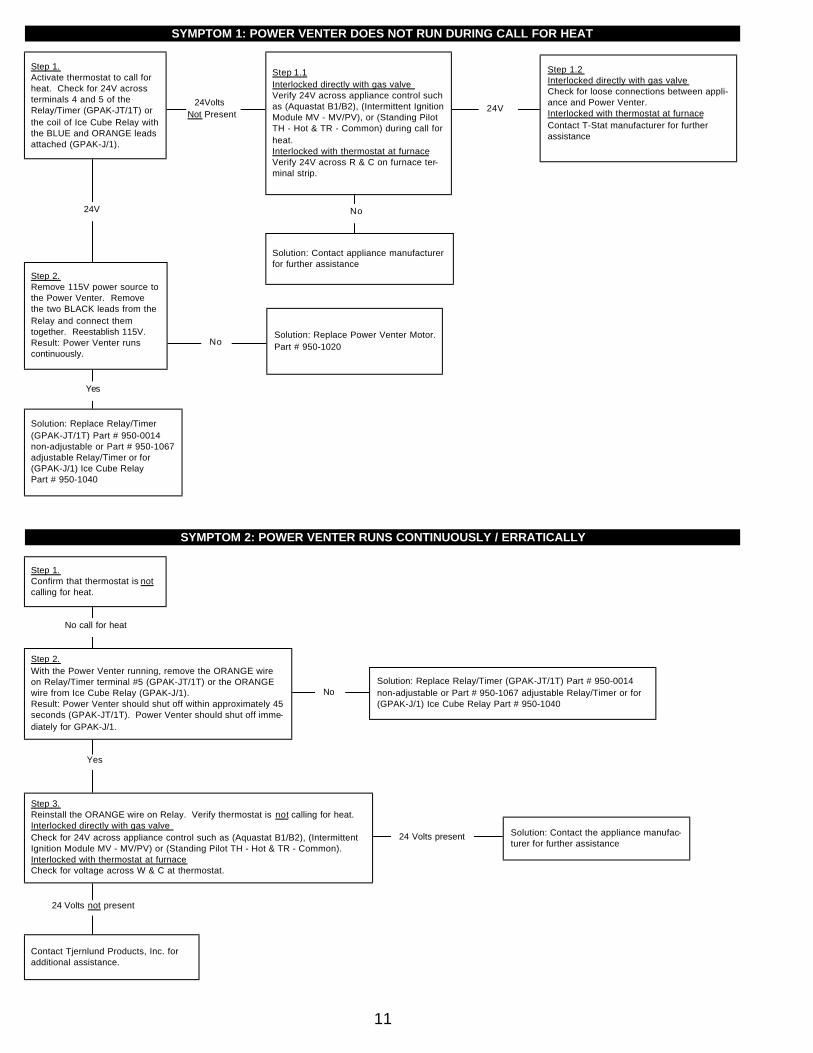
SYMPTOM 1: POWER VENTER DOES NOT RUN DURING CALL FOR HEAT
Step 1.2 Interlocked directly with gas valve Check for loose connections between appli-ance and Power Venter.Interlocked with thermostat at furnaceContact T-Stat manufacturer for furtherassistance
24V24Volts
Not Present
No
No
Solution: Contact appliance manufacturerfor further assistance
Step 1.1Interlocked directly with gas valve Verify 24V across appliance control suchas (Aquastat B1/B2), (Intermittent IgnitionModule MV - MV/PV), or (Standing PilotTH - Hot & TR - Common) during call forheat. Interlocked with thermostat at furnaceVerify 24V across R & C on furnace ter-minal strip.
Step 2.Remove 115V power source tothe Power Venter. Removethe two BLACK leads from theRelay and connect themtogether. Reestablish 115V.Result: Power Venter runscontinuously.
Solution: Replace Relay/Timer(GPAK-JT/1T) Part # 950-0014non-adjustable or Part # 950-1067adjustable Relay/Timer or for(GPAK-J/1) Ice Cube Relay Part # 950-1040
24V
Solution: Replace Power Venter Motor.Part # 950-1020
Yes
Step 1.Activate thermostat to call forheat. Check for 24V acrossterminals 4 and 5 of theRelay/Timer (GPAK-JT/1T) orthe coil of Ice Cube Relay withthe BLUE and ORANGE leadsattached (GPAK-J/1).
SYMPTOM 2: POWER VENTER RUNS CONTINUOUSLY / ERRATICALLY
NoSolution: Replace Relay/Timer (GPAK-JT/1T) Part # 950-0014non-adjustable or Part # 950-1067 adjustable Relay/Timer or for(GPAK-J/1) Ice Cube Relay Part # 950-1040
Solution: Contact the appliance manufac-turer for further assistance
Step 3.Reinstall the ORANGE wire on Relay. Verify thermostat is not calling for heat.Interlocked directly with gas valve Check for 24V across appliance control such as (Aquastat B1/B2), (IntermittentIgnition Module MV - MV/PV) or (Standing Pilot TH - Hot & TR - Common).Interlocked with thermostat at furnaceCheck for voltage across W & C at thermostat.
No call for heat
Contact Tjernlund Products, Inc. foradditional assistance.
24 Volts present
Step 1.Confirm that thermostat is notcalling for heat.
Step 2.With the Power Venter running, remove the ORANGE wireon Relay/Timer terminal #5 (GPAK-JT/1T) or the ORANGEwire from Ice Cube Relay (GPAK-J/1).Result: Power Venter should shut off within approximately 45seconds (GPAK-JT/1T). Power Venter should shut off imme-diately for GPAK-J/1.
Yes
24 Volts not present

MAINTENANCE
1. For optimum motor life, oil motor every six months with 2 drops of S.A.E. #20. The oil ports are located on the top of the motor. Magnetek motors do not need to be oiled.
2. The homeowner must semiannually inspect the Vent Hood and vent pipe for blockage, corrosion and leaks.
3. A vent system inspection must be performed annually by a qualified service agency. The inspection should include the operation circuit check, safety interlock test, combustion air test and a visual inspection of the complete vent system for corrosion, blockage or leaks. Any corrosion, blockage or leaks detected must be repaired or replaced immediately.
HOW TO OBTAIN SERVICE ASSISTANCE
1. If you have any questions about your Power Venter or if it requires adjustment, repair or routine maintenance, we suggest thatyou contact your installer, contractor or service agency.
2. If you require technical information contact Tjernlund Products, Inc. at 1-800-255-4208.
When contacting Tjernlund Products, Inc., please have the following information available:
1. Model name of the Power Venter as shown on the label attached to Power Venter.
2 Name and address of installer and any service agency who performed work on Power Venter.
3. Date of original installation and dates any service work was performed.
4. Details of the problem as you can best describe them.
LIMITED PARTS WARRANTY AND CLAIM PROCEDURE
Tjernlund Products, Inc. warrants the components of its products for one year from date of installation. This warranty covers defectsin material and workmanship. This warranty does not cover normal maintenance, transportation or installation charges for replace-ment parts or any other service calls or repairs. Products that are tampered with, damaged, or defective due to malfunctioning appli-ances are not covered under this warranty. This warranty DOES NOT cover the complete Power Venter if it is operative, except forthe defective part.
12
SYMPTOM 3: POWER VENTER RUNS BUT APPLIANCE DOESN’T
No BadTube
WheelDirty
Contact TjernlundProducts for replace-ment tube.
Clean Power Venter Wheel.
Supply ade-quate combus-tion air, properPower Venter orreduce vent pipelength.
Step 2.Remove the BLUE and YELLOW wires fromPower Venter Proving Switch. Activate ther-mostat to call for heat. With Power Venterrunning, check for continuity across the COMand N/O terminals of Fan Proving Switch.Result: Contacts on switch should be closed.
No call for heat
Contact Tjernlund Products, Inc. foradditional assistance.
Step 1.Confirm that thermostat is notcalling for heat.
Step 3.Replace BLUE to COM and YELLOW to N/O on Fan Proving Switch.Confirm that leads from Fan Prover are connected as follows:Interlocked directly with gas valve YELLOW wire is connected to the TH (HOT) on gas valve and BLUEis connected to appliance control (Aquastat B1), (Intermittent IgnitionModule MV) or (Standing Pilot TH - Hot ).Interlocked with thermostat at furnaceYELLOW wire connected to W on furnace terminal strip and BLUE isconnected to W from T-Stat.
Yes
Yes
Step 2.3Confirm adequate combustion air is present inappliance location, Power Venter is sized properlyfor application and vent runs do not exceed maxi -mum length.
Solution: Replace Fan ProvingSwitch Part # 950-1030
Step 2.2Examine Power Venter wheelfor particulate build-up.
Tube Ok
Yes
Wheel Clean
No
Step 2.1Examine Fan Prover sensing tube forkinks, misalignment or blockage. Sensingtube should be at an approx. 90 degreeangle to wheel.

Tjernlund Products, Inc. will issue credit to the original distributor or provide a free part to replace one that becomes defective during theone year warranty period. If the part is over 18 months old, proof of date of the installation in the form of the contractor sales/installa-tion receipt is necessary to prove the unit has been in service for under one year. All receipts should include the date code of the PowerVenter to ensure that the defective component corresponds with the complete unit. This will help preclude possible credit refusal.
1.) Follow troubleshooting guide to determine defective component. If unable to determine faulty component, contact your Tjernlund distributor or Tjernlund Products Technical Customer Service Department at 1-800-255-4208 for troubleshooting assistance.
2.) After the faulty component is determined, return it to your Tjernlund distributor for replacement. Please include Power Venter datecode component was taken from. The date code is located on the Electrical Box coverplate. If Power Venter date code is older than 18 months you will need to provide a copy of the original installation receipt to your distributor. Credit or replacement will onlybe issued to a Tjernlund distributor after the defective part has been returned prepaid to Tjernlund.
REPLACEMENT PARTS
DESCRIPTION PART NUMBERVent Hood* VH1-4Motor* 950-1020Fan Prover* 950-1030GPAK-JT Wheel 950-1010GPAK-1T Wheel 950-1011GPAK-JT/GPAK-1T Relay/Timer ** (approx. 45 second non-adjustable delay) 950-0014GPAK-JT/GPAK-1T Relay/Timer** (1 to 10 minute adjustable delay) 950-1067
* These parts are common to all GPAK’s ** Either Relay/Timer is suitable for the GPAK-JT/GPAK-1T
WHAT IS NOT COVERED
Product installed contrary to our installation instructionsProduct that has been altered, neglected or misusedProduct that has been wired incorrectlyProduct that has been damaged by a malfunctioning or mistuned burnerAny freight charges related to the return of the defective partAny labor charges related to evaluating and replacing the defective part
PERFORMANCE CURVES
13
TJERNLUND LIMITED ONE YEAR WARRANTY*
Tjernlund Products, Inc. warrants to the original purchaser of this product that the product will be free from defects due to faulty material or workmanship for a period of (1) year from thedate of original purchase or delivery to the original purchaser, whichever is earlier. Remedies under this warranty are limited to repairing or replacing, at our option, any product whichshall, within the above stated warranty period, be returned to Tjernlund Products, Inc. at the address listed below, postage prepaid. THERE ARE NO WARRANTIES WHICH EXTENDBEYOND THE DESCRIPTION ON THE FACE HEREOF, AND TJERNLUND PRODUCTS, INC. EXPRESSLY DISCLAIMS LIABILITY FOR INCIDENTAL OR CONSEQUENTIAL DAM-AGES ARISING FROM THE USE OF THIS PRODUCT. THIS WARRANTY IS IN LIEU OF ALL OTHER EXPRESS WARRANTIES AND NO AGENT IS AUTHORIZED TO ASSUMEFOR US ANY LIABILITY ADDITIONAL TO THOSE SET FORTH IN THIS LIMITED WARRANTY. IMPLIED WARRANTIES ARE LIMITED TO THE STATED DURATION OF THIS LIM-ITED WARRANTY. Some states do not allow limitation on how long an implied warranty lasts, so that limitation may not apply to you. In addition, some states do not allow the exclu-sion or limitation of incidental or consequential damages, so that above limitation or exclusion may not apply to you. This warranty gives you specific legal rights and you may also haveother rights which may vary from State to State. Send all inquiries regarding warranty work to Tjernlund Products, Inc. 1601 9th Street, White Bear Lake, MN 55110-6794. Phone (612)426-2993 • (800) 255-4208 • Fax (612) 426-9547.
*Installations for the HTPV Corrective Action Program have a limited 5 year warranty.
*GPAK-1T**GPAK-JT*

VH1-4 VENT HOOD MOUNTING TEMPLATE
1. Attach the Vent Hood Mounting Template to the interior of the wall the vent hood will be penetrating.
2. Ensure that proposed vent termination clearances are met before attempting to cut opening through exterior wall.
3. Verify that wall penetration will not come in contact with concealed wiring or plumbing. Using a 1/2” drill bit, drill two pilot holes where noted on the template. The drill bit must be long enough to penetrate to the building exterior.
4. Attach the template to the building exterior aligning the pilot holes on the template with the pilot holes drilled in step 3.
5. Using a reciprocating saw, cut an opening through the building siding, wall board, etc., following the appropriate lines of the template.
6. Slide the Vent Hood through the opening and fasten to exterior wall using provided screws.
7. Once Power Venter is completely installed and secured, apply a bead of exterior rated caulk between Vent Hood flange and exterior of building.
CUT OUT THIS SQUARE FOR THE VH1-4” VENT HOOD
14