11-OWB600206 SGSN9810 Gb Interface Data Configuration ISSUE1.0
Upload
elmanzanedaCategory
view
62download
0
www.huawei.com
Copyright © 2010 Huawei Technologies Co., Ltd. All rights reserved.
SGSN9810 Iu Interface Data Configuration
ISSUE2.0

Copyright © 2010 Huawei Technologies Co., Ltd. All rights reserved. Page2
References
3GPP TS 25.413
3GPP TS 23.110
HUAWEI SGSN9810 Serving GPRS Support Node
Operation Manual Data Configuration

Copyright © 2010 Huawei Technologies Co., Ltd. All rights reserved. Page3
Objectives
Upon completion of this course, you will be able to:
Describe the protocol stack and main functions of the
Iu interface.
Configure the data for the Iu over Asynchronous
Transfer Mode (ATM) interface.
Configure the data for the Iu over Internet Protocol (IP)
interface.

Copyright © 2010 Huawei Technologies Co., Ltd. All rights reserved. Page4
Contents
1. Basic Concepts
2. Data Configuration for the Iu over ATM Interface
3. Data Configuration for the Iu over IP Interface

Copyright © 2010 Huawei Technologies Co., Ltd. All rights reserved. Page5
Iu Interface The Iu interface is located between the serving GPRS
support node (SGSN) and the radio network controller
(RNC). On a UMTS network, the Iu interface is mandatory.
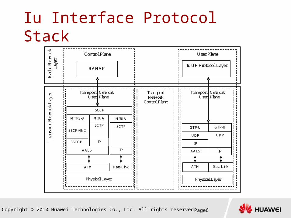
The Iu interface protocol stack consists of the user plane
and control plane.
The Iu user plane uses the GPRS Tunneling Protocol-User Plane
(GTP-U) protocol.
The Iu interface control plane uses the broadband SS7 network.
The transmission over Iu interface can be based on ATM or
IP.
Copyright © 2010 Huawei Technologies Co., Ltd. All rights reserved. Page6
Iu Interface Protocol Stack
IPSSCOP
AAL5
SCTP
MTP3-B M3UA
SCCP
M3UA
RANAPIu UP Protocol Layer
Tra
nspo
rt N
etw
ork
Lay
er
Physical Layer
TransportUser
NetworkPlane
Control Plane User Plane
TransportUser
NetworkPlane
TransportNetwork
Control Plane
Rad
io N
etw
ork
Lay
er
AAL5
IP
UDP
GTP-U
Physical Layer
ATM Data Link
IP
SCTP
Data LinkATM
IP
UDP
GTP-USSCF-NNI

Copyright © 2010 Huawei Technologies Co., Ltd. All rights reserved. Page7
Protocols over the Iu Interface RANAP
The RANAP protocol is used to process signaling message
between the SGSN and the UTRAN and manage the GTP
connection over the Iu interface.
Broadband MTP
The broadband Message Transfer Part (MTP) is implemented by
the MTP3 User Adaptation (M3UA) or Message Transfer Part layer
3-broadband (MTP3B). The signaling messages of the upper layer
are routed and forwarded through broadband MTP.
GTP-U
The GTP-U protocol uses the tunnel to transmit signaling or user
data.
Copyright © 2010 Huawei Technologies Co., Ltd. All rights reserved. Page8
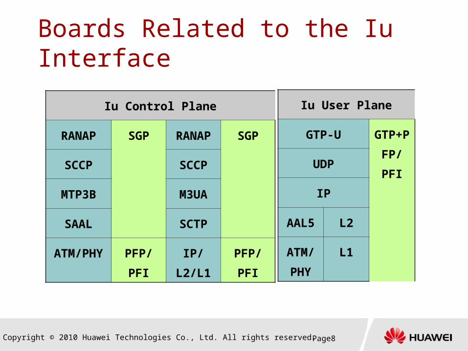
Boards Related to the Iu Interface
Iu Control Plane
RANAP SGP RANA
P
SGP
SCCP SCCP
MTP3B M3UA
SAAL SCTP
ATM/
PHY
PFP/
PFI
IP/L2/
L1
PFP/
PFI
Iu User Plane
GTP-U GTP+
PFP/
PFIUDP
IP
AAL5 L2
ATM/
PHY
L1
Copyright © 2010 Huawei Technologies Co., Ltd. All rights reserved. Page9
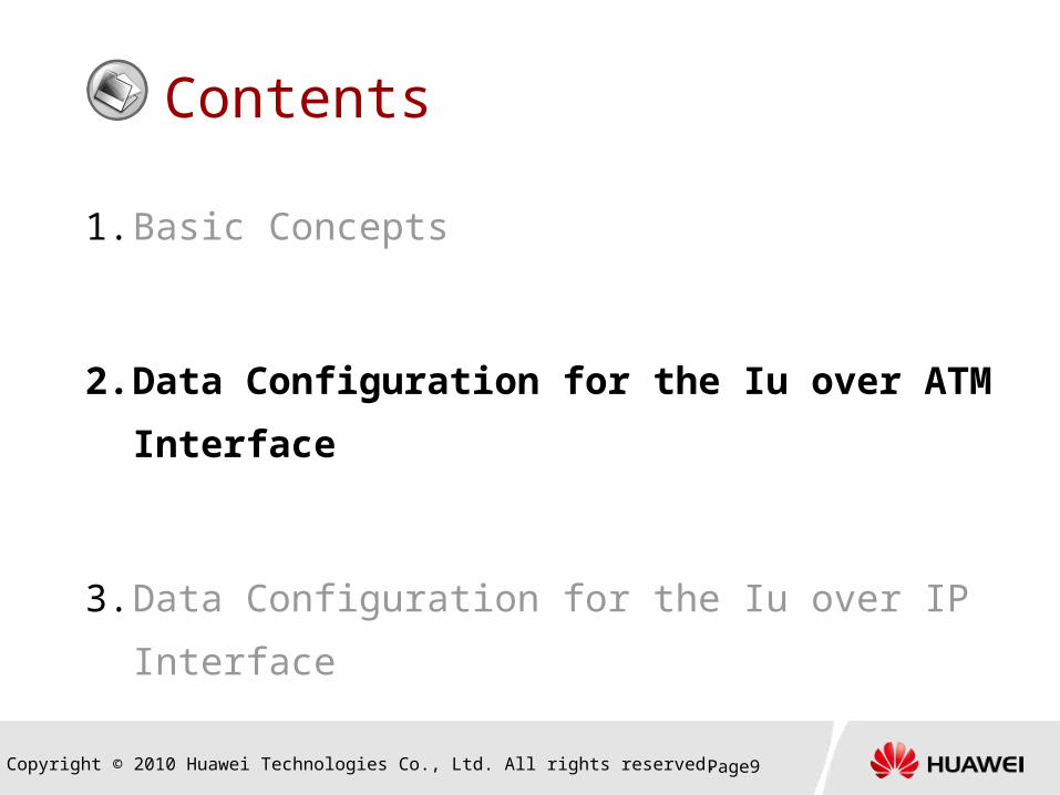
Contents
1. Basic Concepts
2. Data Configuration for the Iu over ATM
Interface
3. Data Configuration for the Iu over IP Interface

Copyright © 2010 Huawei Technologies Co., Ltd. All rights reserved. Page10
Iu over ATM
ATM backbone network
RANAP
SCCP
MTP3B
SAAL(AAL5)
ATM
GTP_U
UDP
IP
AAL5
ATM
RANAP
SCCP
MTP3B
SAAL(AAL5)
ATM
GTP_U
UDP
IP
AAL5
ATM
PVC exchange
IPOA
SAAL link
MTP3B link
PVC exchang
e
Copyright © 2010 Huawei Technologies Co., Ltd. All rights reserved. Page11
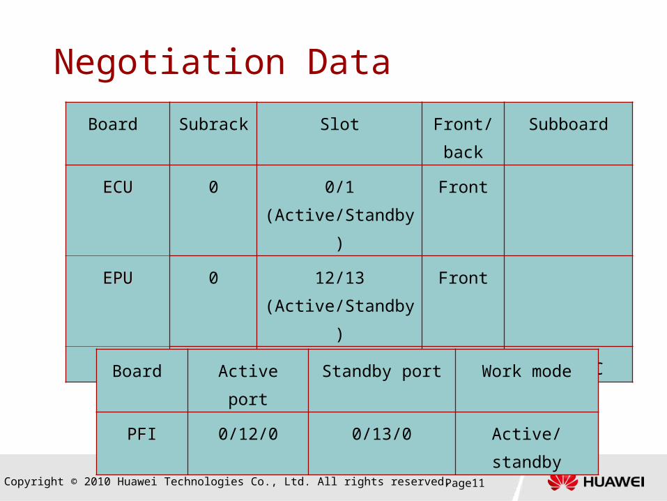
Negotiation Data
Board Subrack Slot Front/
back
Subboard
ECUECU 0 0/1
(Active/Standby)
Front
EPUEPU 0 12/13
(Active/Standby)
Front
PFIPFI 0 12/13 Back AIC/AICAIC/AIC
Board Active port Standby port Work mode
PFIPFI 0/12/0 0/13/0 Active/standby

Copyright © 2010 Huawei Technologies Co., Ltd. All rights reserved. Page12
Negotiation DataPVC traffic parameters
Item Service Type Peak Rate
User plane Uncertain rate 100000
Control plane Stationary rate 3708
User
plane SGSN RNC
IP address of the
user plane
217.164.95.65 100.1.1.1
IP address of IPoA 10.110.0.1/24 10.110.0.2/24
VPI/VCI 1/200
Copyright © 2010 Huawei Technologies Co., Ltd. All rights reserved. Page13
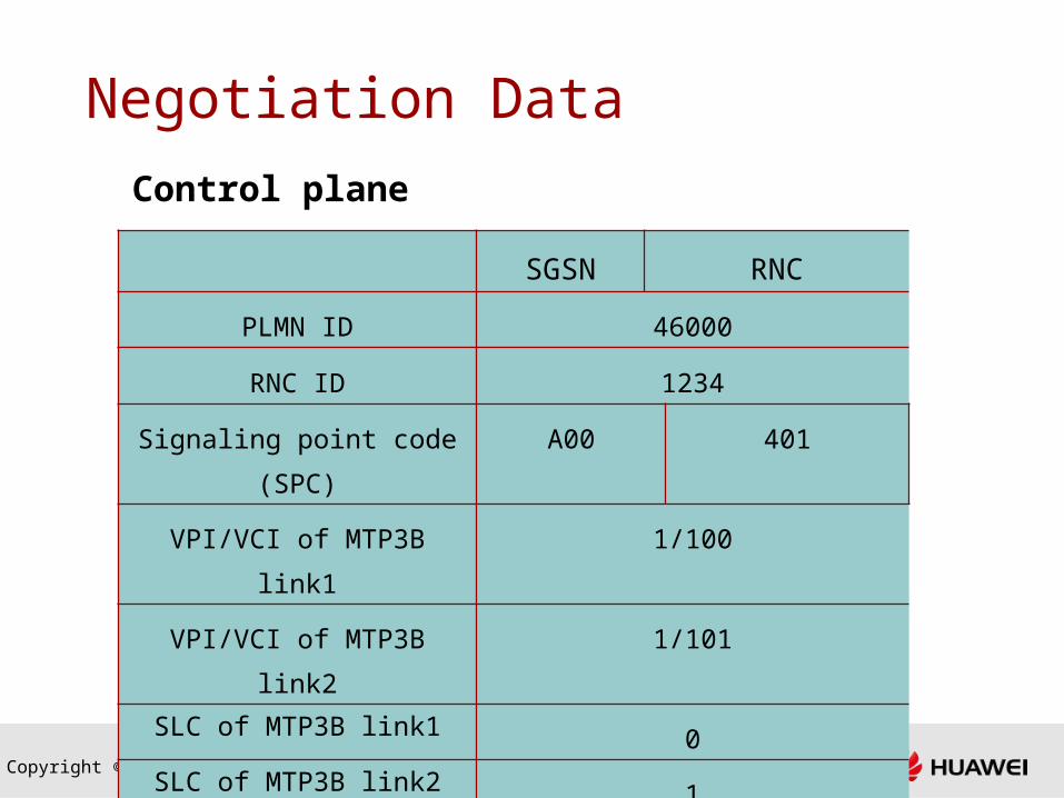
Negotiation Data
Control plane
SGSN RNC
PLMN ID 46000
RNC ID 1234
Signaling point code
(SPC)
A00 401
VPI/VCI of MTP3B link1 1/100
VPI/VCI of MTP3B link2 1/101
SLC of MTP3B link1 0
SLC of MTP3B link2 1

Copyright © 2010 Huawei Technologies Co., Ltd. All rights reserved. Page14
Configuration Steps
Step Operation
Performed on the CGP or SGSN Command
1Configure the
ECU. CGP ADD BRD
2Add ECU-related process groups. SGSN ADD PROCESSGRP
3 Activate the port. CGP ACT PORT
Configuring Boards and Optical InterfacesConfiguring Boards and Optical Interfaces

Copyright © 2010 Huawei Technologies Co., Ltd. All rights reserved. Page15
Configuration Steps
Step Operation Command
Set signaling attributes.
4Set the signaling attributes for the
SGSN. SET SIGATTR
Set the MTP3B attributes.
5Configure an MTP3B originating
signaling point code (OPC). ADD MTP3BOPC
6Configure an MTP3B destination
signaling point code (DPC). ADD MTP3BDPC
7 Configure an MTP3B link set. ADD MTP3BLKS
8Configure an MTP3B signaling
route. ADD MTP3BRT
9 (Optional) Set traffic parameters. ADD TRAFFIC
10 Configure an MTP3B signaling link. ADD MTP3BLNK
11 (Optional) Set the MTP3B timer. SET MTP3BTMR
Configuring Control PlaneConfiguring Control Plane

Copyright © 2010 Huawei Technologies Co., Ltd. All rights reserved. Page16
Configuration StepsStep Operation Command
Configure the signaling connection control part (SCCP).
12 Configure an OPC of the SCCP. ADD SCCPOPC
13 Configure a DPC of the SCCP. ADD SCCPDPC
14Configure the subsystem
number of the SCCP. ADD SCCPSSN
Configure the RNC.
15 Configure the RNC information. ADD RNC
16 Configure the 3G paging table. ADD IUPAGING
17
Configure the mapping between the RNC and the
EPU ADD RNCPFLNK

Copyright © 2010 Huawei Technologies Co., Ltd. All rights reserved. Page17
Configuration Steps
Step Operation Command
18Set the IP address for
the Iu interface. ADD IFIP
19 (Optional) Set traffic parameters. ADD TRAFFIC
20Configure an IPoA link destined for the RNC. ADD IPOA
21Configure the route to the RNC user plane. ADD IPRT
22 (Optional)
Configure the mapping between the RNC and
the UGFU. ADD RNCPFLNK
Configuring User PlaneConfiguring User Plane

Copyright © 2010 Huawei Technologies Co., Ltd. All rights reserved. Page18
Step 1: Configure the ECU
ADD BRD:
Configure the ECU
Example
ADD BRD: SRN=0, SN=0, METYPE=SGSN,
FBRDHTYP=UPBA3, APPTYPE=ECU;
ADD BRD: SRN=0, SN=1, METYPE=SGSN,
FBRDHTYP=UPBA3, APPTYPE=ECU;

Copyright © 2010 Huawei Technologies Co., Ltd. All rights reserved. Page19
Step 2: Add ECU-related Process Groups
ADD PROCESSGRP:
Set the two ECUs at SRN 0 and SN 0, and SRN 0 and SN
1 to operate in active/standby mode, and then add
related process groups on the ECUs.
ADD PROCESSGRP: SRN=0, SN=0, PSN=1,
PROCGRP=ECUGP_8;
Copyright © 2010 Huawei Technologies Co., Ltd. All rights reserved. Page20
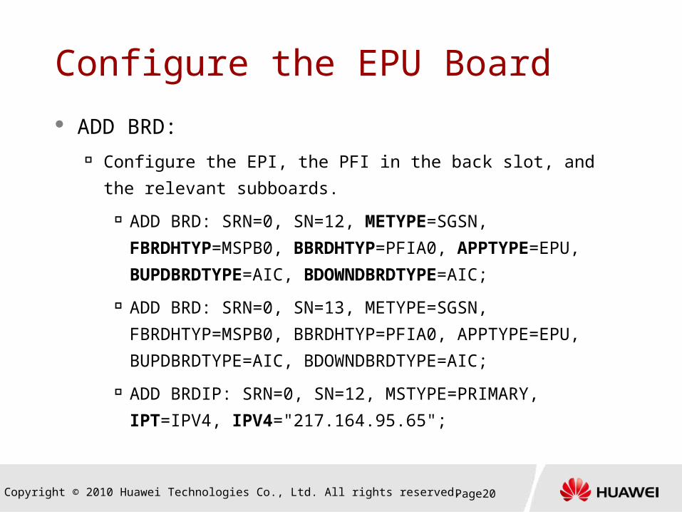
Configure the EPU Board
ADD BRD: Configure the EPI, the PFI in the back slot, and the relevant
subboards.
ADD BRD: SRN=0, SN=12, METYPE=SGSN,
FBRDHTYP=MSPB0, BBRDHTYP=PFIA0, APPTYPE=EPU,
BUPDBRDTYPE=AIC, BDOWNDBRDTYPE=AIC;
ADD BRD: SRN=0, SN=13, METYPE=SGSN,
FBRDHTYP=MSPB0, BBRDHTYP=PFIA0, APPTYPE=EPU,
BUPDBRDTYPE=AIC, BDOWNDBRDTYPE=AIC;
ADD BRDIP: SRN=0, SN=12, MSTYPE=PRIMARY,
IPT=IPV4, IPV4="217.164.95.65";
Copyright © 2010 Huawei Technologies Co., Ltd. All rights reserved. Page21
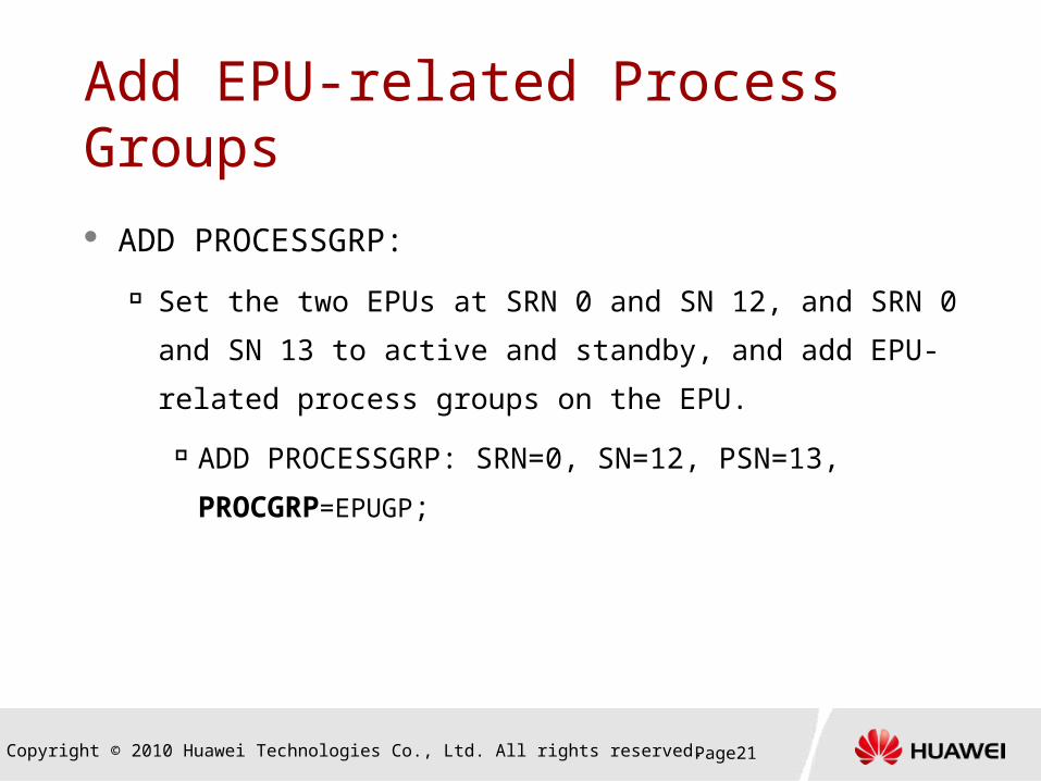
Add EPU-related Process Groups ADD PROCESSGRP:
Set the two EPUs at SRN 0 and SN 12, and SRN 0 and
SN 13 to active and standby, and add EPU-related
process groups on the EPU.
ADD PROCESSGRP: SRN=0, SN=12, PSN=13,
PROCGRP=EPUGP;

Copyright © 2010 Huawei Technologies Co., Ltd. All rights reserved. Page22
Step 3: Activate the Port
ACT PORT:
Activate the port of the SRN 0 and SN 12, and SRN0 and SN 13.
ACT PORT: SRN=0, SN=12, PORTID=1;
ACT PORT: SRN=0, SN=13, PORTID=1;
MOD PORT:
MOD PORT: SRN=0, SN=12, PORTID=1,
PORTTYPE=ATM, PEERSN=13, PEERPID=1,
FRAMEFMT=SDH;

Copyright © 2010 Huawei Technologies Co., Ltd. All rights reserved. Page23
Planning the IP Address for the Iu Interface
Optical cable Logical IP
217.164.95.65
10.110.0.1/2410.110.0.2/24
IPoA link
RNC SGSN
100.1.1.1

Copyright © 2010 Huawei Technologies Co., Ltd. All rights reserved. Page24
Step 4: Configure the Signaling Attributes for the Iu Interface SET SIGATTR
Set or modify the signaling attributes of the local
office.
The attributes of the signaling network determine the
signaling attributes supported by the local office.
Example
SET SIGATTR: IF=INVALID, IRF=INVALID,
NF=LABEL24, NRF=LABEL14, BSSAPPF=ENABLE,
SS7T=ITUT_SS7;
Copyright © 2010 Huawei Technologies Co., Ltd. All rights reserved. Page25
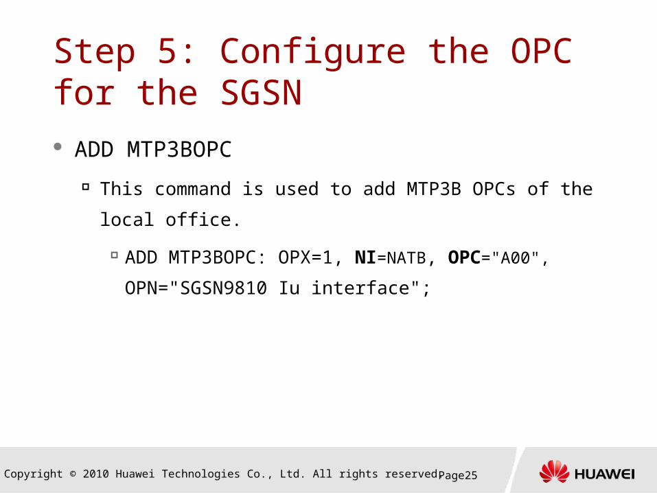
Step 5: Configure the OPC for the SGSN ADD MTP3BOPC
This command is used to add MTP3B OPCs of the local
office.
ADD MTP3BOPC: OPX=1, NI=NATB, OPC="A00",
OPN="SGSN9810 Iu interface";

Copyright © 2010 Huawei Technologies Co., Ltd. All rights reserved. Page26
ADD MTP3BDPC
Add the MTP3B DPC.
ADD MTP3BDPC: DPX=0, OPX=0, DPC="401",
SLSSM=B0000, STPF=DISABLE, ADJF=TRUE,
DPN="RNC Iu Interface";
Step 6: Configure the DPC for the RNC

Copyright © 2010 Huawei Technologies Co., Ltd. All rights reserved. Page27
Step 7: Configure the Signaling Link Set
ADD MTP3BLKS
Configure the MTP3B signaling link set between the
SGSN and the RNC.
ADD MTP3BLKS: LSX=1, DPX=1, SLSM=B0000;

Copyright © 2010 Huawei Technologies Co., Ltd. All rights reserved. Page28
Step 8: Configure the MTP3B Signaling Route
ADD MTP3BRT
Configure the MTP3B signaling route between the
SGSN and the RNC.
ADD MTP3BRT: RTX=1, DPX=1, LSX=1;
Copyright © 2010 Huawei Technologies Co., Ltd. All rights reserved. Page29
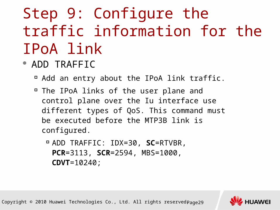
Step 9: Configure the traffic information for the IPoA link ADD TRAFFIC
Add an entry about the IPoA link traffic. The IPoA links of the user plane and control
plane over the Iu interface use different types of QoS. This command must be executed before the MTP3B link is configured.
ADD TRAFFIC: IDX=30, SC=RTVBR, PCR=3113, SCR=2594, MBS=1000, CDVT=10240;
Copyright © 2010 Huawei Technologies Co., Ltd. All rights reserved. Page30
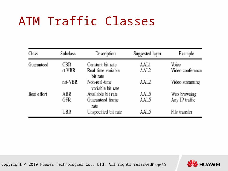
ATM Traffic Classes

Copyright © 2010 Huawei Technologies Co., Ltd. All rights reserved. Page31
Step 10: Configure the MTP3B Link ADD MTP3BLNK
Configure the signaling link between the SGSN9810 and the RNC.
When the configuration of this command takes effect, the SGSN9810 generates an SAAL link. An SAAL link corresponds to an MTP3B link.
Example ADD MTP3BLNK: LNK=1, IFSRN=0, IFSN=12,
IFPORT=0, PVPI=1, PVCI=100, SRN=0, SN=2, PRN=0, LSX=1, SLC=0, STRAFI=30;
Copyright © 2010 Huawei Technologies Co., Ltd. All rights reserved. Page32
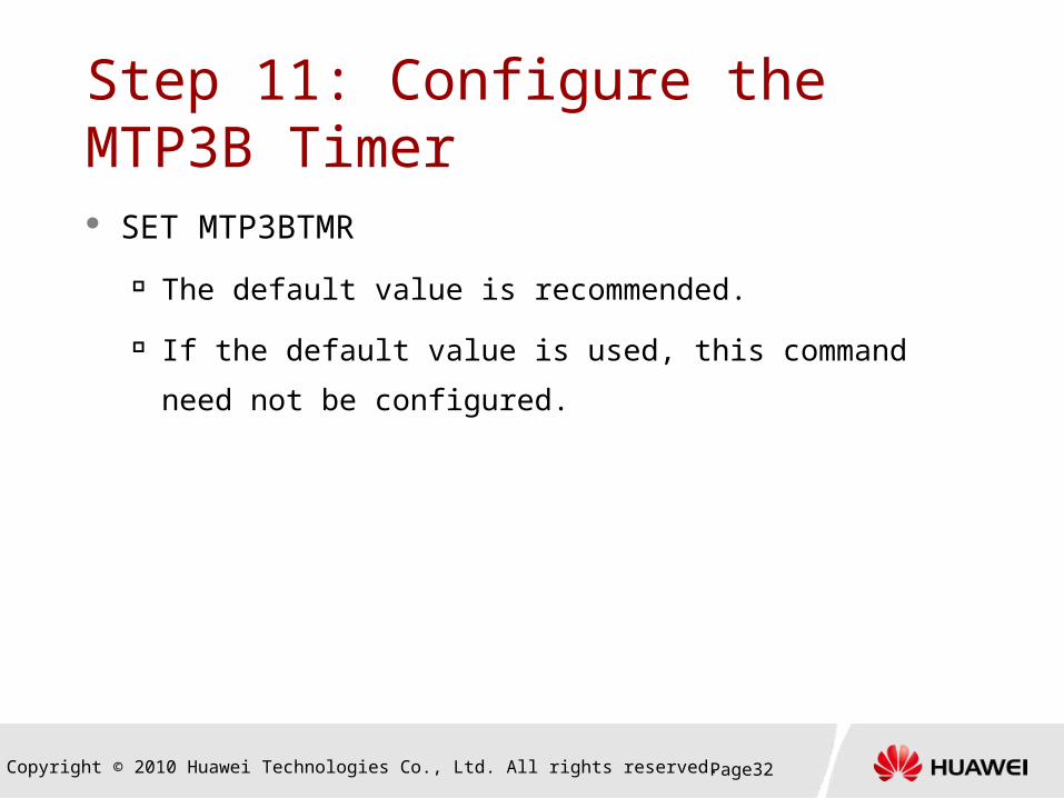
Step 11: Configure the MTP3B Timer SET MTP3BTMR
The default value is recommended.
If the default value is used, this command need not be
configured.

Copyright © 2010 Huawei Technologies Co., Ltd. All rights reserved. Page33
Step 12: Configure the OPC of the SCCP ADD SCCPOPC
Configure the OPC of the SCCP for the SGSN.
ADD SCCPOPC: OPX=1, NI=NATB,
OPC="a00", SPN=IUONLY;

Copyright © 2010 Huawei Technologies Co., Ltd. All rights reserved. Page34
Step 13: Configure the DPC of the SCCP ADD SCCPDPC
Configure the DPC of the SCCP for the SGSN.
The DPC of the SCCP must be the signaling
point that is defined in the MTP3B layer.
ADD SCCPDPC: DPX=1, OPX=1,
DPC="A00", LDP=nouse, DPN="RNC";

Copyright © 2010 Huawei Technologies Co., Ltd. All rights reserved. Page35
Step 14: Configure the subsystem number of the SCCP ADD SCCPSSN
Configure the subsystem number related to the Iu interface for the SGSN.
ADD SCCPSSN: SSNX=1, SSN=SCMG, NI=NATB, DPC="401", OPC="A00", SSNNAME="scmg";
ADD SCCPSSN: SSNX=2, SSN=RANAP, NI=NATB, DPC="401", OPC="A00", SSNNAME="RANAP";
Note: SSN is the user of the MTP3B.
SCMG: SCCP management subsystem
RANAP: radio access network application part subsystem

Copyright © 2010 Huawei Technologies Co., Ltd. All rights reserved. Page36
Step 15: Configure RNC information. ADD RNC
Configure the RNC information.
ADD RNC: RNCX=1, RNCMCC="460",
RNCMNC="00", RNCID=1234, NI=NATB,
SPC="401";
Copyright © 2010 Huawei Technologies Co., Ltd. All rights reserved. Page37
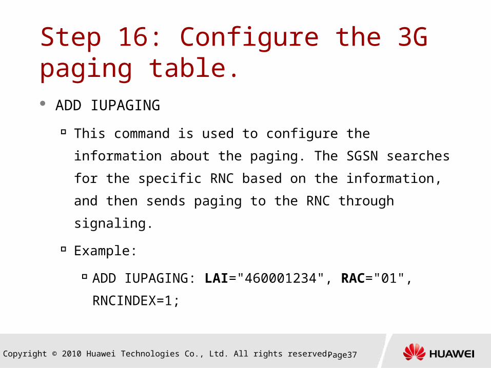
Step 16: Configure the 3G paging table. ADD IUPAGING
This command is used to configure the information
about the paging. The SGSN searches for the specific
RNC based on the information, and then sends paging
to the RNC through signaling.
Example:
ADD IUPAGING: LAI="460001234", RAC="01",
RNCINDEX=1;

Copyright © 2010 Huawei Technologies Co., Ltd. All rights reserved. Page38
Step 17: Add relation link of RNC and EPU
add a direct user plane IP link between the RNC and
the EPU. "Direct" means the link does not need to
be routed by other EPU.
ADD RNCPFLNK

Copyright © 2010 Huawei Technologies Co., Ltd. All rights reserved. Page39
Step 18: Set the IP address for the user plane of the Iu interface. ADD IFIP
This command is used to configure the IP
addresses for both the active port and sub-
interface on the EPU board.
ADD IFIP: SRN=0, SN=12, PN=0, IPT=PRI,
IP="10.110.0.1", MSK="255.255.255.0",
DESC="interface to RNC1";
EPU
IPOAIP1 IP2
IP4IP3
RNC SGSN
Copyright © 2010 Huawei Technologies Co., Ltd. All rights reserved. Page40
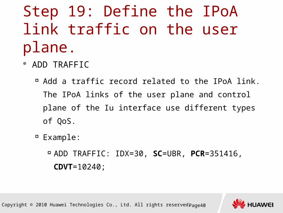
Step 19: Define the IPoA link traffic on the user plane.
ADD TRAFFIC
Add a traffic record related to the IPoA link. The IPoA
links of the user plane and control plane of the Iu
interface use different types of QoS.
Example:
ADD TRAFFIC: IDX=30, SC=UBR, PCR=351416,
CDVT=10240;

Copyright © 2010 Huawei Technologies Co., Ltd. All rights reserved. Page41
Step 20: Configure the IPoA link. ADD IPOA
Configure the IPoA link for the user plane of the Iu interface.
ADD IPOA: SRN=0, SN=12, PN=0, VPI=1, VCI=200,
TP=STATIC_MAP, IP="10.110.0.2", TRAF=30, QOS=0;
Copyright © 2010 Huawei Technologies Co., Ltd. All rights reserved. Page42
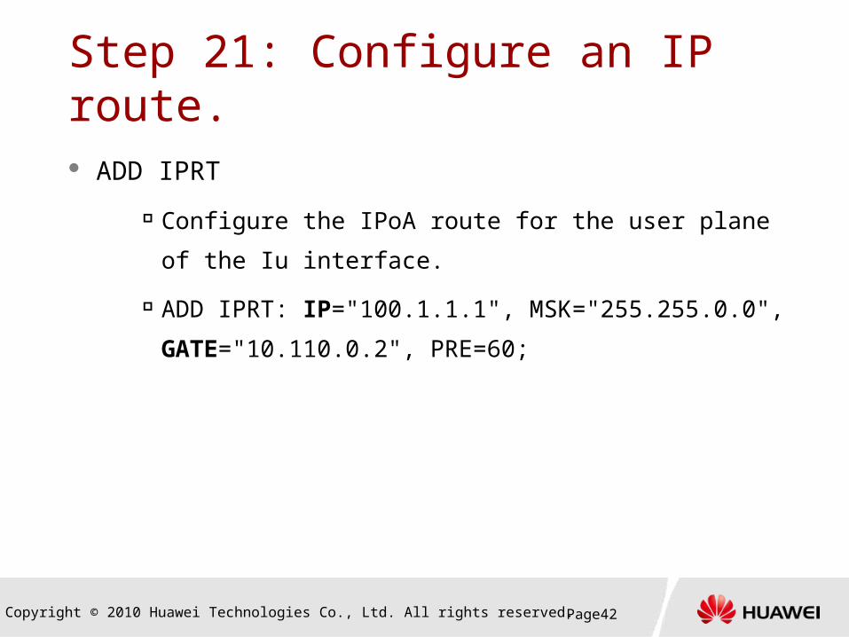
Step 21: Configure an IP route.
ADD IPRT
Configure the IPoA route for the user plane of the Iu
interface.
ADD IPRT: IP="100.1.1.1", MSK="255.255.0.0",
GATE="10.110.0.2", PRE=60;

Copyright © 2010 Huawei Technologies Co., Ltd. All rights reserved. Page43
Checking the Control Plane Status MTP3B link status
DSP MTP3BLNK: SRT=ALL;
SCCP DPC status
DSP SCCPDPC: SSNX=2, NI=NATB, DPC="401",
SSN=RANAP;
SCCP subsystem status
DSP SCCPSSN: SSNX=2, NI=NATB, DPC="401",
SSN=RANAP;

Copyright © 2010 Huawei Technologies Co., Ltd. All rights reserved. Page44
Checking the User Plane Status
The DSP GTPPATH command is used to
display the user plane status.
DSP GTPPATH: GTPPATHTYPE=GTPU,
SUBRACKNO=0, SLOTNO=12, PATHINTFTYPE=GU,
IPTYPE=IPV4, PEERIPV4ADDR="100.1.1.1";
Copyright © 2010 Huawei Technologies Co., Ltd. All rights reserved. Page45
Contents
1. Basic Concepts
2. Data Configuration for the Iu over ATM
Interface
3. Data Configuration for the Iu over IP
Interface

Copyright © 2010 Huawei Technologies Co., Ltd. All rights reserved. Page46
Iu over IP
IPIP
RNANP
SCCP
M3UA
SCTP
IP
GTP_U
UDP
IP
RNANP
SCCP
M3UA
SCTP
IP
GTP_U
UDP
IP
M3UA link
IPIP

Copyright © 2010 Huawei Technologies Co., Ltd. All rights reserved. Page47
Iu over IP Network
Ethernet interfaceLogical IP
address
10.110.0.1/2410.10.10.2/24
100.1.1.1
RNC SGSN
RR
10.110.0.3/24
DPC=3333
IP address of the signaling
plane = 10.11.12.12
OPC=1111
SGP
l M3UAl IP=10.10.12.14l GTP-U:
217.164.95.65
EPU ECU
Copyright © 2010 Huawei Technologies Co., Ltd. All rights reserved. Page48
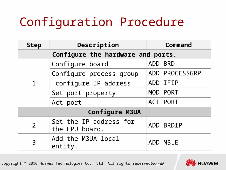
Configuration Procedure
Step Description Command
Configure the hardware and ports.
1
Configure board ADD BRD
Configure process group ADD PROCESSGRP
configure IP address ADD IFIP
Set port property MOD PORT
Act port ACT PORT
Configure M3UA
2Set the IP address for the EPU board.
ADD BRDIP
3 Add the M3UA local entity. ADD M3LE
Copyright © 2010 Huawei Technologies Co., Ltd. All rights reserved. Page49
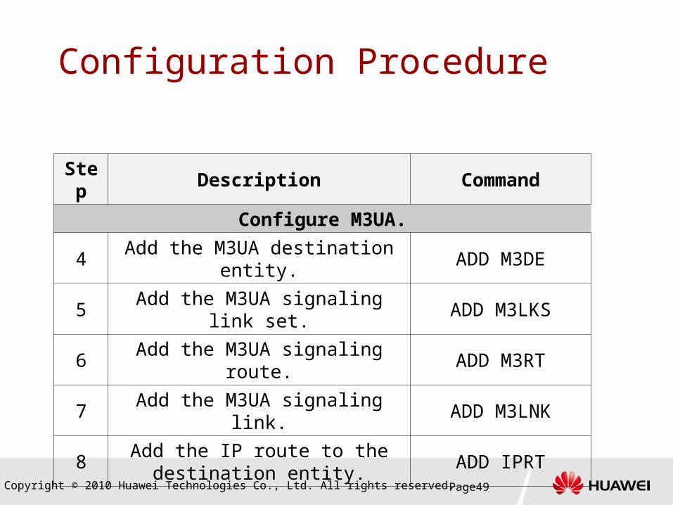
Configuration Procedure
Step
Description Command
Configure M3UA.
4Add the M3UA destination
entity.ADD M3DE
5Add the M3UA signaling link
set.ADD M3LKS
6 Add the M3UA signaling route. ADD M3RT
7 Add the M3UA signaling link. ADD M3LNK
8Add the IP route to the
destination entity.ADD IPRT

Copyright © 2010 Huawei Technologies Co., Ltd. All rights reserved. Page50
Configuration ProcedureStep Purpose Command
Configure the SCCP layer.
9 Add the SCCP OPC. ADD SCCPOPC
10 Add the SCCP DPC. ADD SCCPDPC
11 Add the SCCP subsystem. ADD SCCPSSN
Configure the RNC.
12 Add the RNC information. ADD RNC
13 Add the 3G paging table. ADD IUPAGING
14Configure the mapping
between the RNC and the EPU
ADD RNCPFLNK

Copyright © 2010 Huawei Technologies Co., Ltd. All rights reserved. Page51
Configuration Procedure
Step Purpose CommandConfigure the user plane information.
15(Optional)
Configure the UPIU port on the user plane.
ADD IFIPACT PORT
16 Add routes. ADD IPRT
17Configure the GTPU IP
addressADD
BINDGTPUIP

Copyright © 2010 Huawei Technologies Co., Ltd. All rights reserved. Page52
Step 1: Configure the Hardware ADD BRD
Add the ECU, EPU, or PFI.
ADD PROCESSGRP Add the process group on the ECU and EPU. Refer to the
information about Iu over ATM.
ADD IFIP Configure the interface IP address of PFI.
MOD PORT, ACT PORT Set the Ethernet port type and activate the port.
Copyright © 2010 Huawei Technologies Co., Ltd. All rights reserved. Page53
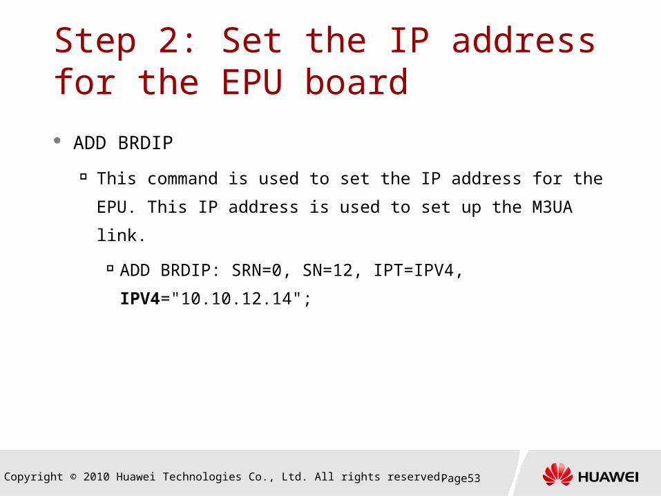
Step 2: Set the IP address for the EPU board
ADD BRDIP
This command is used to set the IP address for the
EPU. This IP address is used to set up the M3UA link.
ADD BRDIP: SRN=0, SN=12, IPT=IPV4,
IPV4="10.10.12.14";
Copyright © 2010 Huawei Technologies Co., Ltd. All rights reserved. Page54
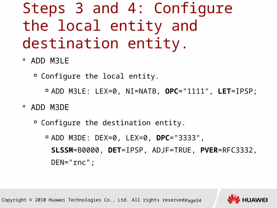
Steps 3 and 4: Configure the local entity and destination entity. ADD M3LE
Configure the local entity.
ADD M3LE: LEX=0, NI=NATB, OPC="1111", LET=IPSP;
ADD M3DE
Configure the destination entity.
ADD M3DE: DEX=0, LEX=0, DPC="3333",
SLSSM=B0000, DET=IPSP, ADJF=TRUE,
PVER=RFC3332, DEN="rnc";

Copyright © 2010 Huawei Technologies Co., Ltd. All rights reserved. Page55
M3UA Entity Type
M3UA link
IPSPIPSP
SGSN HLR
M3UA link
SGPASP
SGSN HLRSGMTP3 link
SP

Copyright © 2010 Huawei Technologies Co., Ltd. All rights reserved. Page56
Steps 5 and 6: Configure the link set and route.
ADD M3LKS
Configure the link set.
ADD M3LKS: LSX=0, ADX=0, SLSM=B0000,
WM=IPSP, TM=LOADSHARE, LSN="LINKSET1";
ADD M3RT
Configure the M3UA route.
ADD M3RT: RTX=0, DEX=0, LSX=0, PRI=0,
RTN="TO rnc";
Copyright © 2010 Huawei Technologies Co., Ltd. All rights reserved. Page57
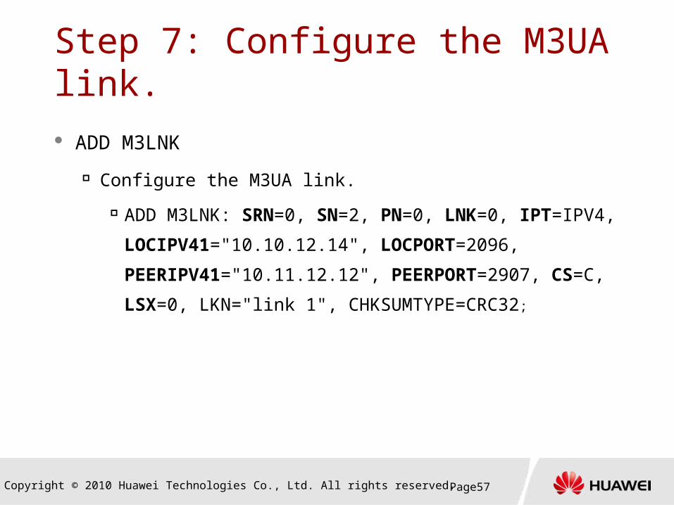
Step 7: Configure the M3UA link. ADD M3LNK
Configure the M3UA link.
ADD M3LNK: SRN=0, SN=2, PN=0, LNK=0,
IPT=IPV4, LOCIPV41="10.10.12.14",
LOCPORT=2096, PEERIPV41="10.11.12.12",
PEERPORT=2907, CS=C, LSX=0, LKN="link 1",
CHKSUMTYPE=CRC32;

Copyright © 2010 Huawei Technologies Co., Ltd. All rights reserved. Page58
Step 8: Configure the IP route for the control plane.
ADD IPRT
Configure the IP route for the control plane.
ADD IPRT: IP="10.11.12.12", MSK="255.255.255.0",
GATE="10.110.0.3";

Copyright © 2010 Huawei Technologies Co., Ltd. All rights reserved. Page59
Step 9 through Step 13
Step 9 through Step 13 are used to configure
the SCCP layer. The configuration procedure is
the same as that for the Iu over ATM interface.

Copyright © 2010 Huawei Technologies Co., Ltd. All rights reserved. Page60
Step 14: Add relation link of RNC and EPU
add a direct user plane IP link between the RNC and
the EPU. "Direct" means the link does not need to
be routed by other EPU.
ADD RNCPFLNK

Copyright © 2010 Huawei Technologies Co., Ltd. All rights reserved. Page61
Step 15: Configure the PFI port on the user plane. If the user plane and control plane use different
physical Ethernet ports, the following commands are
required to configure the port information and
interface IP address for the user plane.
ACT PORT
ADD IFIP
In this example, the user plane and control plane use
the same port.

Copyright © 2010 Huawei Technologies Co., Ltd. All rights reserved. Page62
Step 16: Configure the route on the user plane.
ADD IPRT
Configure the route on the user plane.
ADD IPRT: IP="100.1.1.1", MSK="255.255.255.0",
GATE="10.110.0.3";

Copyright © 2010 Huawei Technologies Co., Ltd. All rights reserved. Page63
Step 17: Configure the GTPU IP address
ADD BINDGTPUIP
Add IP address of a board to serve as the IP address of
the GTP user plane.
ADD BINDGTPUIP: IPT=IPV4, IPV4=" 10.10.12.14 ",
ITFDRT=IUPS;

Copyright © 2010 Huawei Technologies Co., Ltd. All rights reserved. Page64
Iu over IP Interface Status Checking Check the control plane status.
DSP M3DE: DEX=1;
DSP M3RT: RTX=1;
DSP M3LNK: SRT=LINK, SRN=0, SN=13, LNK=0;
DSP SCCPDPC: DPX=1;
DSP SCCPSSN: SSNX=2, NI=NATB, DPC="401", SSN=RANAP;
Check the user plane status.
TST GTPPATH: GTPPATHTYPE=GTPU, PATHINTFTYPE=GU,
IPTYPE=IPV4, LOCIPV4ADDR="217.164.95.65",
PEERIPV4ADDR="100.1.1.1";

Thank youwww.huawei.com