Overview of the Kemper County IGCC Project Using · PDF fileR = drag, inwc/(ft/min)/(lb/ft2) R...
18
Overview of the Kemper County IGCC Project Using Transport Integrated Gasification (TRIG TM ) Coal Barn Emergency Crushed Coal Coal Transport Integrated Gasification (TRIG TM ) Flare Derricks Control/Admin Bldg Coal Preparation Gasifiers, Syngas Coolers, PCDs Process Air Compressors Stack Coal Loading Hoppers Combined Water Treatment Bldg Sulfuric Acid Production Cooling Towers Cycle CO 2 /Sulfur Removal Area 2010 Gasification Technology Conference 2010 Gasification Technology Conference Washington, D. C. - November 1, 2010
Transcript of Overview of the Kemper County IGCC Project Using · PDF fileR = drag, inwc/(ft/min)/(lb/ft2) R...

Overview of the Kemper County IGCC Project Using Transport Integrated Gasification (TRIGTM)
Coal BarnEmergency Crushed Coal
Coal
Transport Integrated Gasification (TRIGTM)
Flare Derricks
Control/Admin Bldg
Coal Preparation
Gasifiers, Syngas Coolers, PCDsProcess Air
Compressors
StackCoal Loading Hoppers
Combined
Water Treatment Bldg
Sulfuric Acid Production
Cooling Towers
CycleCO2/Sulfur Removal Area
2010 Gasification Technology Conference2010 Gasification Technology ConferenceWashington, D. C. - November 1, 2010

Kemper County IGCC Project Overview2x1 Integrated Gasification Combined Cycle (IGCC)2x1 Integrated Gasification Combined Cycle (IGCC)
– 2 TRansport Integrated Gasifiers (TRIG™)– 2 Siemens SGT6 - 5000F CTs– 1 Toshiba Steam Turbine (Tandem Compound Double Flow)
582 MW k d 524 MW – 582 MW peak and 524 MW on syngas– Heat Rate 11,708 Btu/kWh (29.5% HHV Efficiency w/ CO2
control and 40+% moisture coal)– Selexol for H2S and CO2 removal
65+% CO t ( 800 lb/ Wh i i t )
Plant SitePlant Site
– 65+% CO2 capture (~800 lb/mWh emission rate)– Mine Mouth Lignite
Owner & Operator: Mississippi PowerOver $2 billion capital investmentCommercial Operating Date: May 2014Use treated effluent from Meridian as makeup waterBy-Products (TPY)
~3 000 000 - Carbon dioxide used for EOR– 3,000,000 - Carbon dioxide used for EOR– ~135,000 - Sulfuric acid– ~20,000 - Ammonia
Kemper Lignite CompositionAverage Min Max
Heat Content btu/lb 5,290 4,765 5,870Moisture % 45.5 42 50Ash % 12.0 8.6 17Sulfur % 1.0 0.35 1.7

Kemper County IGCC Project Map Plant Site
Meridian
~ 70 miles transmission
~ 60 miles CO2 pipeline (for EOR)2 p p ( )
~5 miles natural gas pipeline
~31,000 acre mine site
~2,900 acres plant siteNew CO2Pipeline
~ 30 miles treated effluent line
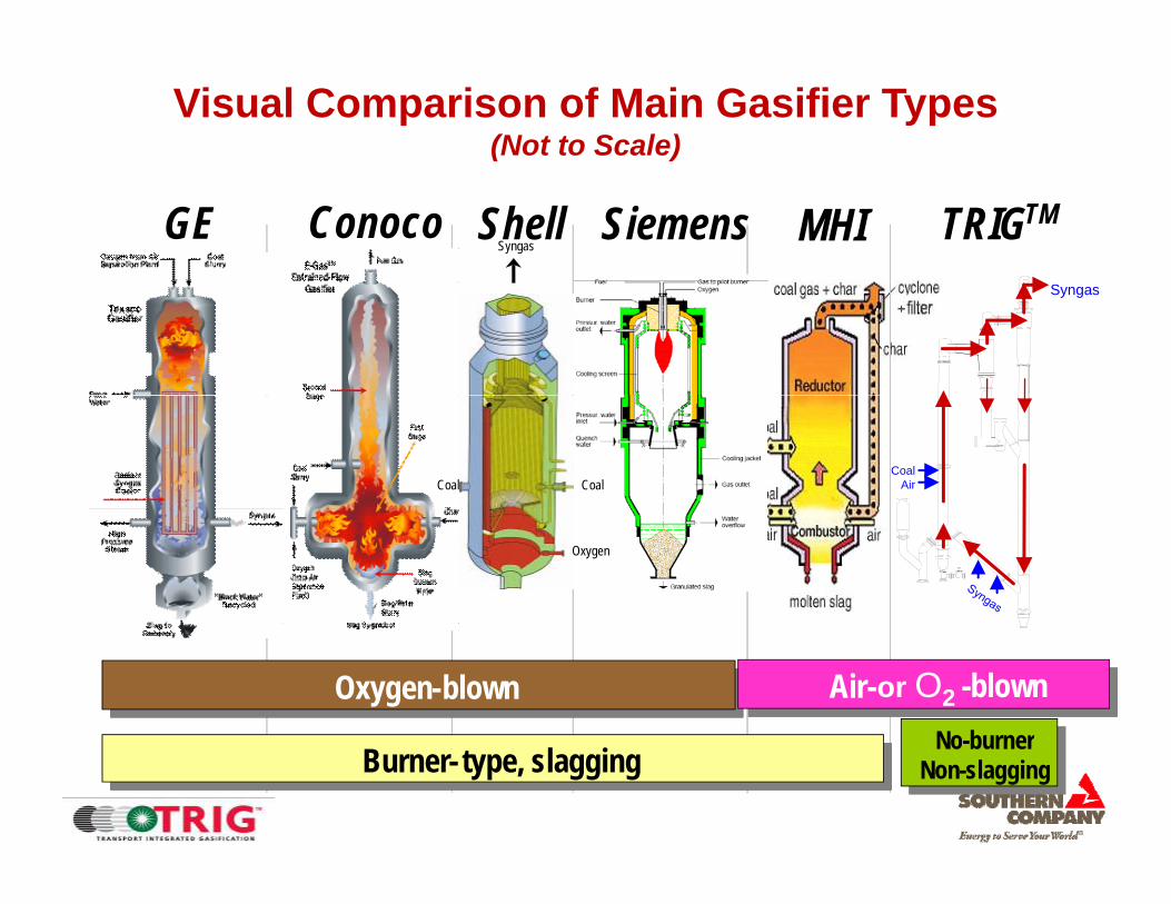
Visual Comparison of Main Gasifier Types(Not to Scale)
GE Conoco TRIGTMShell SiemensSyngas
MHISyngas
CoalCoalCoal
Air
Oxygen
Oxygen-blownThe image cannot be displayed. Your computer may not have enough memory to open the image, or the image may have been corrupted. Restart your computer, and then open the file again. If the red x still appears, you may have to delete the image and then insert it again.
Oxygen-blownThe image cannot be displayed. Your computer may not have enough memory to open the image, or the image may have been corrupted. Restart your computer, and then open the file again. If the red x still appears, you may have to delete the image and then insert it again.
No burner-blown
The image cannot be displayed. Your computer may not have enough memory to open the image, or the image may have been corrupted. Restart your computer, and then open the file again. If the red x still appears, you may have to delete the image and then insert it again.
Air- -blownor O2
Burner- type, slaggingThe image cannot be displayed. Your computer may not have enough memory to open the image, or the image may have been corrupted. Restart your computer, and then open the file again. If the red x still appears, you may have to delete the image and then insert it again.
Burner- type, slagging No-burnerNon-slaggingNo-burner
Non-slagging

Development of the TRIG™ for Power and Chemical ProductionChemical Production
TRIGTM Leverages Long History of KBR Fluid Catalytic Cracking (FCC) Expertise
FirstC i l Late
30's
1942
CommercialFCC Unit
for Exxon
Orthoflow™A Design
1951
Early
Orthoflow™C Design
ResidFCCs Early
1960's
19761980's 1990 1996 1996 China 2011 USA 2014
FCCs
Orthoflow™ F Design
Design Based on FCC Technology
Pilot PlantTech Center
Grand Forks, ND2,600 Hours Test Run
PSDF at Wilsonville, AL. >14,600 hrs in gasification >2,200 hrs on
TRIGTM In Kemper County, MS, USA & Dong Guan, China
Mississippi Lignitethru Dec ‘09

TRIGTM IGCC Attributes / Advantages
Simple, Well Established Design– Based on technology in use for 70 years
Either Air- or Oxygen-Blown
First Separation
Device
Syngas
yg– Air for power– Oxygen for liquid fuels and chemicals
High Reliability Design– Non-slagging design:
RiserSecond
Separation Device
Provides 10-20 year refractory life Eliminates black water systemProvides non-fouling syngas cooler operation
– No burners to fail and be replaced– Dry dust removal eliminates gray water system
Upper Mixing Zone
Seal Lower Fuel Costs
– Coarse, dry coal feed allows:Fewer, lower power pulverizersLess drying than other dry-feed gasifiers
Cost effective using high moisture high ash low
Standpipe
J-Leg
Seal LegCoal
Air
– Cost-effective using high moisture, high-ash, low rank coals (PRB and lignite)
Excellent Environmental Performance– Lower water use compared to pulverized coal (PC)– Excellent emissions performanceLower
Startup Burner
Stp
– Lower cost carbon capture compared to PCLower Mixing Zone
SteamOxygen

Kemper Primary Syngas Cooler(Commercial Design by Borsig)
PDSF cooler Inlet after 1300 hrs operation
Non-slagging design leads to no fouling vs slagging gasifier designsNever fouled with coal ash Temperature reduction ~800 to 1000 0F

Dry Particulate Filtration – Proven OperationPressure Drop – Note Return to Baseline after each Pulse
Beginning of run End of run
Pressure Drop – Note Return to Baseline after each Pulse
Sizing Hot Gas Filters Based on Ash Characteristics
Stable baseline pressure dropExcellent filtration performance >99.9999%Highly reliable failsafe system Typical Run Outlet Particle Loading
2 42.83.2
on, p
pmw
Turbine specification, 2.4 ppmw
Failsafes
R = drag, inwc/(ft/min)/(lb/ft2)
Relat
ive F
ilter S
ize
100150
200
250300
350
400 Subbituminous, 40% CarbonSubbituminous, 25% CarbonLignite, 10% CarbonLignite, 20% Carbon
0.40.81.21.6
22.4
e C
once
ntra
ti
Note Margin
Allowable Pressure Drop, inH2O60 80 100 120 140 160 180 200
R
050 0
0 100 200 300 400 500 600Run HoursPa
rtic
l

Kemper Dry Ash Filter(Commercial Design By Pall)( g y )

Continuous Coarse Ash DepressurizationContinuous Coarse Ash Depressurization(Gasifier Level Control Performance)
240
230
235
Level / SPT
220
225
210
215 • 100% Reliability since 1st Day of Operation • High Capacity• No Moving Parts
N P i i G N d d
CCAD Level Ctrlr CCAD Level Ctrlr 1:00 2:00 3:00 4:00 5:00 6:00 7:00 8:00 9:00 10:00 11:00 12:00 13:00 14:00 15:00 16:00 17:00
205
200
• No Pressurizing Gas Needed• Small & Clean Gas Venting• Transport using inherent gas
Confidential and Proprietary

Typical Coal Feed Particle SizeTransport Gasifier vs Pulverized Coal p
161820
mic
rons
, %
90
100
Sieve Size, Mesh
1420354248606580100
115
150
170
200
250
270
325
400
810121416
grea
ter t
han
1180
m
Moisture Content Must Also Be <25%
% P
assi
ng
50
60
70
80
02468
cent
age
of P
artic
le g
0 0 0 0 0 0 0 0 0 0 0 0 0 00 010
20
30
40
PC Boiler Transport Gasifier
0 5 10 15 20 25 30Percentage of Particle less than 45 microns, %
Perc
PDAC Feeder Operation
Particle Size, μm
40 50 60 70 80 90 200
300
400
500
600
700
800
900
100
1000
Feed
Rat
e, lb
/hr
M d C l F d R t
0 2 4 6 8 10 12 14 16 18 20 22 24Time, hours
Coa
l F Measured Coal Feed Rate
Coal Feed Rate Setpoint

Kemper CO2 Capture SchemeTwo Stages WGSSelexol Physical SolventRefrigerated to 40°F
Carbon Capture: 65+%CO2 Emissions: 800 lb CO2/MWhYield: >3 MM Tons/yr CO2

Kemper County TRIGTM 3-D PerspectiveHRSGs
Gas Turbines Steam Turbine
Air Compressors
HP Coal Feeders
CO2 and H2S RemovalRemoval
Gasifiers (2)
Fluid Bed Dryer System
Sulfuric Acid ProductionProduction

Flare Derricks
Kemper County TRIGTM 3-D Perspective
Sour Water/NH3 Recovery System
H2S Absorbers (2)
Particulate Collection Device (PCD)
Dry Ash Filters (4)
CO2 Compressors
AGR Regenerators
Crushed Coal Silos
Gasifiers (2)
CO2 Absorbers (6)
CO2 Flash Drums (8)
Main Syngas Coolers (4)
HP Coal Feeders (12)
2 ( )
Syngas COS Hydrolysis
NH3 Removal
Mercury Adsorbers
Coal Mills (6)Back-pulse
S D
WGS R t
y gHumidifiers
COS HydrolysisSurge Drums
Admin. Bldg.
Steam Turbine
Process Air Compressors
WGS ReactorsWarehouse

Kemper County TRIGTM(A Sense of Scale)( )
Water Gas Shift (WGS) Reactors
(12)WGS RecuperatorWGS R t
High Temp Syngas Recuperator (2)
Syngas Saturator/Scrubber Recuperator (2)
WGS Recuperator (2)
WGS Reactor Isolation Valves
Recuperator (2)
6’ Person

Kemper Status/Summary ScheduleOn June 3, 2010, the Mississippi Public Service Commission issued a Certificate of Convenience & Necessity for the project authorizing construction. Construction began after PSC certification. DOE has issued a Record of Decision on for the NEPA process related to CCPI funding.MDEQ i d th fi l PSD it M h 9 2010MDEQ issued the final PSD permit on March 9, 2010.2009
1st 2nd 3rd 4th2010 2013 201420122011
1st 2nd 3rd 4th 1st 2nd 3rd 4th 1st 2nd 3rd 4th1st 2nd 3rd 4th1st 2nd 3rd 4th
Detail DesignLong Lead Procurement
Bulk Equip. Procurement Sitework
Piling/CaissonsFoundations
Today
FoundationsGI General Contractor
CC General ContractorStart-up
CODy CO

Kemper CountyConstruction Mid-Oct 2010Initial clearing & grubbing for TRIG™ site complete
Earthwork to begin Week of 10/4g
Foundation work to begin next year.
Majority of construction work slated for 2012.

TRIGTM IGCC Attributes / Advantages
Simple, Well Established Design– Based on technology in use for 70 years
Either Air- or Oxygen-Blown
First Separation
Device
Syngas
yg– Air for power– Oxygen for liquid fuels and chemicals
High Reliability Design– Non-slagging design:
RiserSecond
Separation Device
Provides 10-20 year refractory life Eliminates black water systemProvides non-fouling syngas cooler operation
– No burners to fail and be replaced– Dry dust removal eliminates gray water system
Upper Mixing Zone
Seal Lower Fuel Costs
– Coarse, dry coal feed allows:Fewer, lower power pulverizersLess drying than other dry-feed gasifiers
Cost effective using high moisture high ash low
Standpipe
J-Leg
Seal LegCoal
Air
– Cost-effective using high moisture, high-ash, low rank coals (PRB and lignite)
Excellent Environmental Performance– Lower water use compared to pulverized coal (PC)– Excellent emissions performanceLower
Startup Burner
Stp
– Lower cost carbon capture compared to PCLower Mixing Zone
SteamOxygen