Overview Controls in CMS DCS Project Planning Controls in the CMS Experiment JCOP Review 10-12 March...
28
Overview Controls in CMS DCS Project Planning Controls in the CMS Experiment JCOP Review 10-12 March 2003 J. Varela, LIP-Lisbon
-
date post
19-Dec-2015 -
Category
Documents
-
view
220 -
download
0
Transcript of Overview Controls in CMS DCS Project Planning Controls in the CMS Experiment JCOP Review 10-12 March...

Overview
Controls in CMS
DCS Project Planning
Controls in the CMS Experiment
JCOP Review 10-12 March 2003
J. Varela, LIP-Lisbon
CMS-DCS, JCOP Review 10-03-03 J. Varela
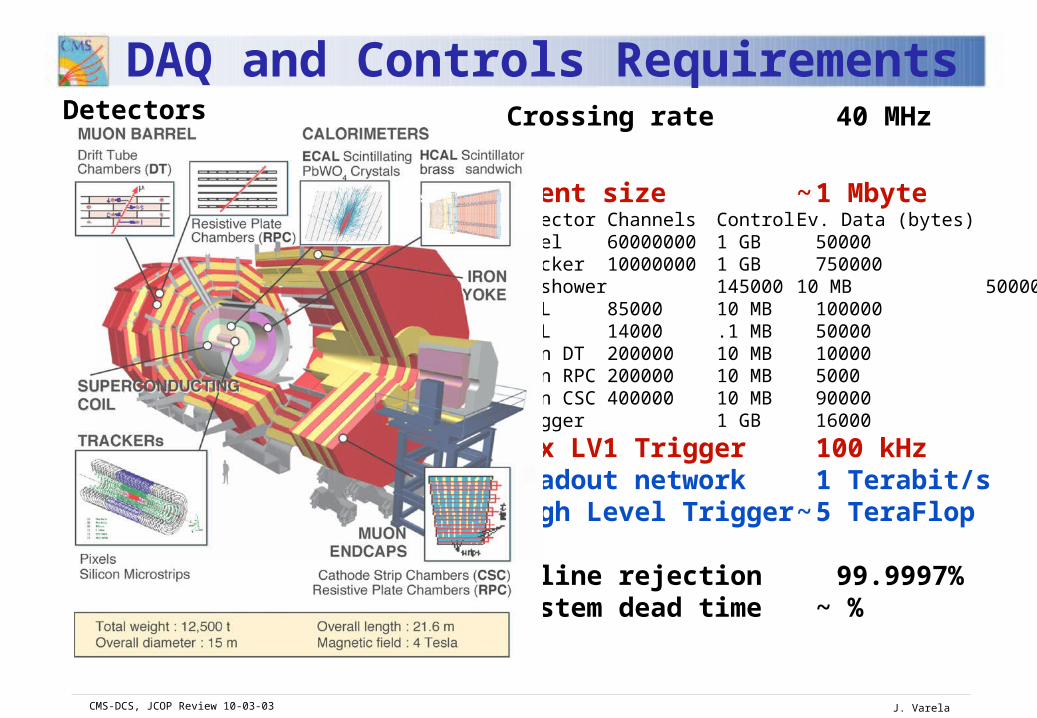
Crossing rate 40 MHz
Event size ~ 1 MbyteDetector Channels Control Ev. Data (bytes)Pixel 60000000 1 GB 50000Tracker 10000000 1 GB 750000Preshower 145000 10 MB 50000ECAL 85000 10 MB 100000HCAL 14000 .1 MB 50000Muon DT 200000 10 MB 10000Muon RPC 200000 10 MB 5000Muon CSC 400000 10 MB 90000Trigger 1 GB 16000
Max LV1 Trigger 100 kHzReadout network 1 Terabit/sHigh Level Trigger ~ 5 TeraFlop
Online rejection 99.9997%System dead time ~ %
Detectors
DAQ and Controls Requirements

CMS-DCS, JCOP Review 10-03-03 J. Varela
Experiment Controls
Run Controls (RCS):Configure and operate all local/global data taking sessionsMonitor and protect the measurements and the data flow
Based on the CMS online software framework (XDAQ, RCS) and commercial products (DBs, SOAP, XML, e-tools etc.)
Detector Controls (DCS):Setup and monitor thedetectors and the environment Monitor and protect the apparatus equipment
Based on industry standards (PLC, field buses, PVSS and JCOP tools)
CMS-DCS, JCOP Review 10-03-03 J. Varela
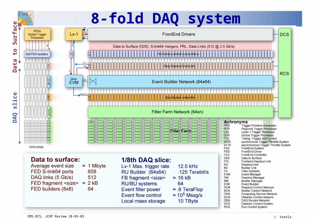
8-fold DAQ systemD
ata
to S
urf
ace
DA
Q s
lice
CMS-DCS, JCOP Review 10-03-03 J. Varela
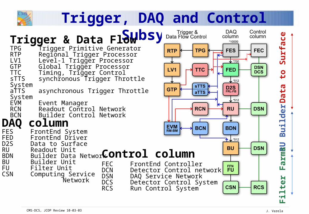
Trigger, DAQ and Control Subsystems
Da
ta t
o S
urf
ace
RU
Bu
ilder
Filt
er
Far
ms
Trigger & Data FlowTPG Trigger Primitive GeneratorRTP Regional Trigger ProcessorLV1 Level-1 Trigger ProcessorGTP Global Trigger ProcessorTTC Timing, Trigger Control sTTS synchronous Trigger Throttle SystemaTTS asynchronous Trigger Throttle SystemEVM Event ManagerRCN Readout Control NetworkBCN Builder Control Network
DAQ columnFES FrontEnd SystemFED FrontEnd DriverD2S Data to SurfaceRU Readout UnitBDN Builder Data NetworkBU Builder UnitFU Filter UnitCSN Computing Service Network
Control columnFEC FrontEnd ControllerDCN Detector Control networkDSN DAQ Service NetworkDCS Detector Control SystemRCS Run Control System
CMS-DCS, JCOP Review 10-03-03 J. Varela
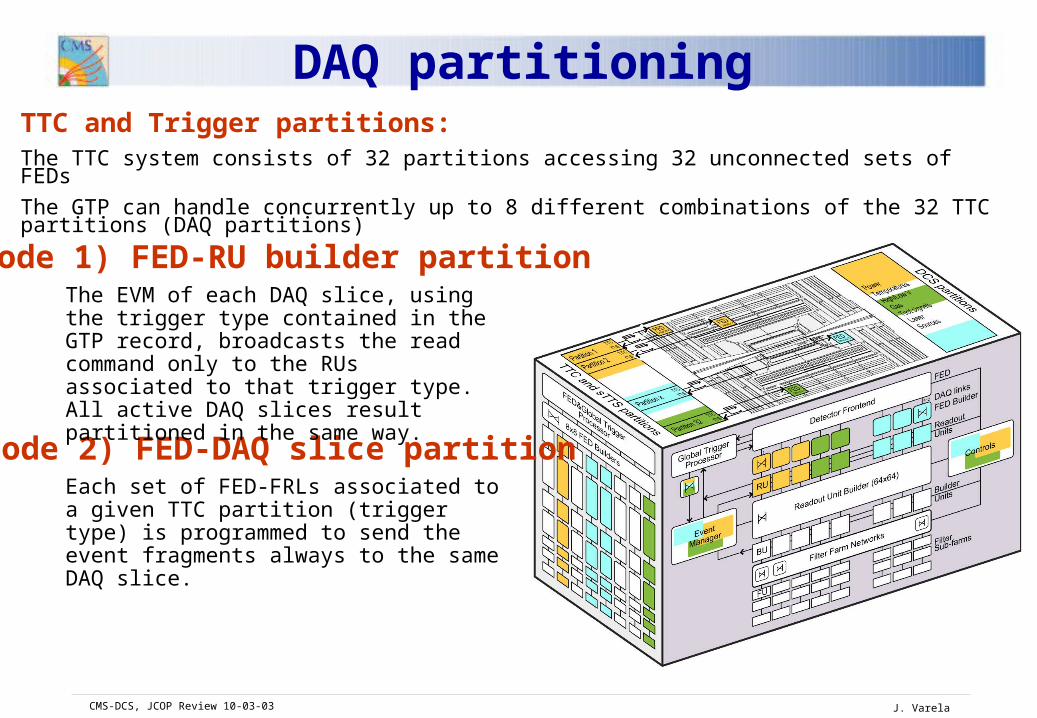
DAQ partitioningTTC and Trigger partitions: The TTC system consists of 32 partitions accessing 32 unconnected sets of FEDs
The GTP can handle concurrently up to 8 different combinations of the 32 TTC partitions (DAQ partitions)
Each set of FED-FRLs associated to a given TTC partition (trigger type) is programmed to send the event fragments always to the same DAQ slice.
Mode 1) FED-RU builder partition
Mode 2) FED-DAQ slice partition
The EVM of each DAQ slice, using the trigger type contained in the GTP record, broadcasts the read command only to the RUs associated to that trigger type. All active DAQ slices result partitioned in the same way.

CMS-DCS, JCOP Review 10-03-03 J. Varela
Trigger Fast Control
Global Trigger Global Trigger TTCmiTTCmi DAQ Event Managers
DAQ Event Managers
Partition ControlPartition Control
TTCrxTTCrx
FrontEnd
Partition ControlPartition Control
TTCrxTTCrx
FrontEnd
Partition ControlPartition Control
TTCTTC sTTSsTTS TTCTTC sTTSsTTS TTCTTC sTTSsTTS
TTCrxTTCrx
FrontEnd
Central Control aTTSaTTSLHC GPS
LHC GPS
Local Control
Local Control
Local Control
Local Control
Local Control
Local Control
Local Triggers
L1A Control
Front-end Emulators, Trigger Rules
Trigger Throttling System (sTTS and aTTS)
Calibration and Test Triggers
Dedicated runs, Special triggers during runs
Synchronization ControlTiming signals, Resync procedures
Partitioning
8 independent partition groups, 8 independent triggers
CMS-DCS, JCOP Review 10-03-03 J. Varela
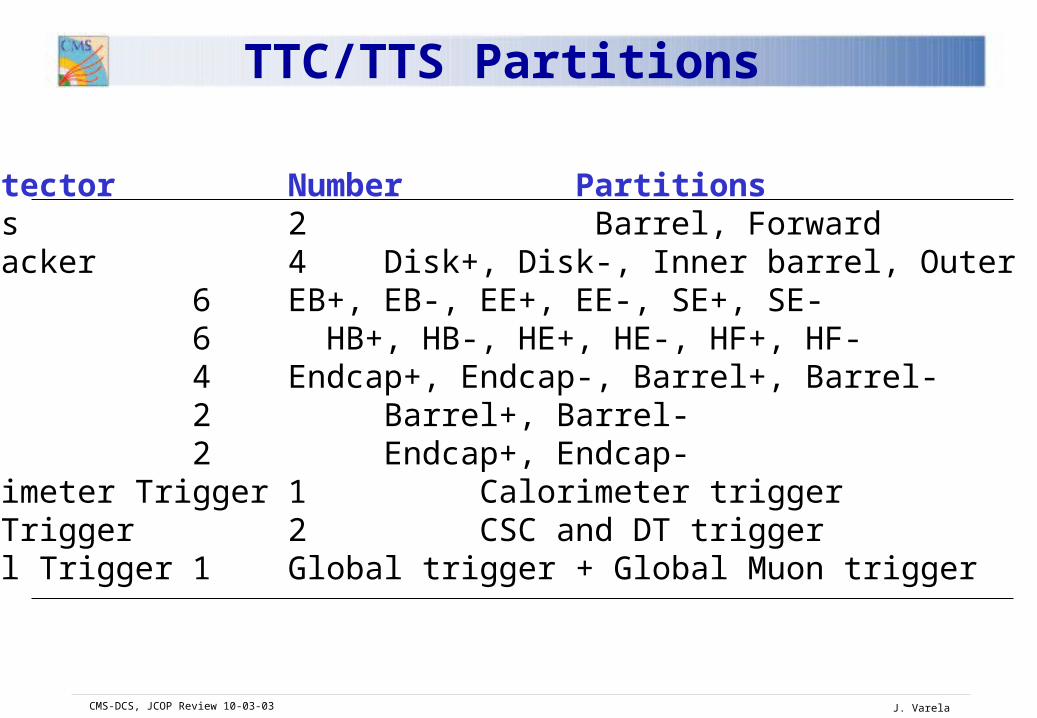
Subdetector Number PartitionsPixels 2 Barrel, ForwardSi-Tracker 4 Disk+, Disk-, Inner barrel, Outer barrelECAL 6 EB+, EB-, EE+, EE-, SE+, SE-HCAL 6 HB+, HB-, HE+, HE-, HF+, HF-RPC 4 Endcap+, Endcap-, Barrel+, Barrel-DT 2 Barrel+, Barrel-CSC 2 Endcap+, Endcap-Calorimeter Trigger 1 Calorimeter trigger Muon Trigger 2 CSC and DT triggerGlobal Trigger 1 Global trigger + Global Muon trigger
TTC/TTS Partitions

CMS-DCS, JCOP Review 10-03-03 J. Varela
Frontend Readout Systems

CMS-DCS, JCOP Review 10-03-03 J. Varela
LOCAL (VME)
GL
OB
AL
Slin
k-6
4
Detector Data Taking (DAQ systems)
Local DAQ- VME/PCI FED data acquisition- Test beam DAQ systems- Test and Calibration readout- Online passive readoutGlobal DAQ- Main DAQ data streamRun Control and Monitor- Supervision of all data taking operations- DAQ resource and partition handling- Readout subsystems configuration- Data flow monitoring- DCS communication

CMS-DCS, JCOP Review 10-03-03 J. Varela
FrontEnd Configuration and Monitor
Detector specific systems Access to the inner readout electronics, the power regulators, the programmable logics, the sensors to read currents, temperatures etc..Special requirements imposed detector specific solutions.
-Data links and interfaces-Programmable Logic (FPGA,..) controls-Sensors readout -Calibration and test procedures
The configuration data set are often very large. The collected data (temperature and currents) are data complementary of the measurement instead of control parameters.
All Detector Safety Units make use of dedicated and wired sensors

CMS-DCS, JCOP Review 10-03-03 J. Varela
Detector Control (DCS systems)Detector subsystems
-HV/LV-Fluids and environment-Cooling-Racks/Crates-Temperatures-Infrastructures-Test systems (Laser, LED, alignment camera etc..)
Detector safety (DSS)-Temperature-Gas-Radiation
Experiment supervision-DCS Resources handling-Alarm and loggings-History data base-External systems communication.
Supervisor structure etc.
TPG Trigger Primitive GeneratorRTP Regional Trigger ProcessorLV1 Level-1 Trigger ProcessorGTP Global Trigger ProcessorTTC Timing, Trigger Control sTTS synchronous Trigger Throttle SystemaTTS asynchronous Trigger Throttle SystemFES FrontEnd SystemFED FrontEnd DriverFEC FrontEnd ControllerD2S Data to SurfaceRU Readout UnitBU Builder UnitFS Filter SubfarmEVM Event ManagerRM Readout ManagerBM Builder ManagerEVB Event BuilderRCN Readout Control NetworkBCN Builder Control NetworkCSN Computing Service NetworkDCN Dtector Control networkDSN DAQ Service NetworkDCS Detector Control SystemRCS Run Control System

CMS-DCS, JCOP Review 11-03-03 J. Varela
Frontend Control Systems
CMS-DCS, JCOP Review 11-03-03 J. Varela
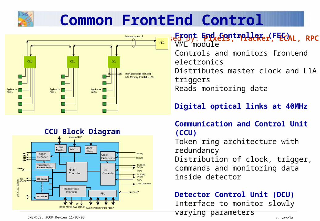
Common FrontEnd ControlUsed by: Pixels, Tracker, ECAL, RPC
CCU Block Diagram
Front End Controller (FEC) VME moduleControls and monitors frontend electronicsDistributes master clock and L1A triggersReads monitoring data
Digital optical links at 40MHz
Communication and Control Unit (CCU)Token ring architecture with redundancyDistribution of clock, trigger, commands and monitoring data inside detector
Detector Control Unit (DCU)Interface to monitor slowly varying parameters

CMS-DCS, JCOP Review 11-03-03 J. Varela
HCAL DCS Layout
Industrial PC, Linux
HV power supplies
RBXRBX
Private system servers
(PVSS systems)
User PCs(PVSS Uis)
200m
Co
un
tin
g r
oo
m
HCAL host
RS422
Hub-18 RS/RS
Cav
ern
RBXFE boards,
LED calibration module,Monitoring modules 18 RBXs
HV,LV
Laser,RBXs,
Sources
Hub-18 RS/RS
CCMLV power
supplyLV power supplyLV power
supply
Truncated CCM
RS422
RS422 fan-out HV power supplies
14 permanent drivers
PCI interface
Industrial PC, Linux
RS422 fan-out
To sources
RS485
RS485
HF radiation monitoring
Drivers for tmp srcs
To temporary sources

CMS-DCS, JCOP Review 11-03-03 J. Varela
CFEB
48 peripheral crates
VME
DCS PC(s)
DB
SCADA
PVSS II
Low VoltageDistribution Board
Anode LCT Board
Cathode FrontEnd Board
DAQ Mother Board Trigger Mother Board Clock Control Board Muon Port Card
Endcap Muon Chamber
Dyn
ate
m
D
MB
C
CB
T
MB
Crate PS
AL
CT
LV
DB
LV
MBLow Voltage
Mezzanine Board
Skewclear LV
HV
gas
cooling
alignment
Calibration local DAQ
M
PC
Ethernet 10-Base-FL
MuonCSC DCS Layout

CMS-DCS, JCOP Review 11-03-03 J. Varela
MuonDT DCS Layout
• SLOW CONTROL MASTER
– Sits in the counting room
– 250 RS232 optical connections
– Houses the DCS interface
• SERIAL LINKS
– One direct link from each control board to counting room
– One direct link from half wheel control board to counting room
– One daisy chained link from sector collector to control boards (half wheel)
– One local link for maintenance

CMS-DCS, JCOP Review 10-03-03 J. Varela
RCS: Data Acquisition SystemsBased on the CMS online software framework (XDAQ, RCS) and commercial products (DBs, SOAP, XML, e-tools etc.)-Run Control and Monitor-Local/Global DAQ systems-FrontEnd Electronics Configuration-Readout Electronics Configuration-PC clusters and applications control-Local/Remote Data Archive-Run Condition Data Base-Configuration Data Base
DCS: Classic ControlBased on industry standards (PLC, field buses, PVSS and JCOP tools)-Racks/Crates power-HV/LV supplies-Cooling and environment-Gas and fluids-Central supervision-Alarms, history data base-External system communication-Detector Safety
Detector specific monitoring and calibration tasksUser applications mainly based on XDAQ with direct interfaces with local/central DCS systems-On detector electronics sensors (temperatures, currents, …)-FrontEnd electronics test and commissioning procedures-Calibration (source, LED, Laser) sessions
RCS and DCS Domains

CMS-DCS, JCOP Review 10-03-03 J. Varela
Silicon Tracker
Pedestal run
Test pulse run
Synchronization run
Optical link special run
Linearity run
Alignment run
MIP calibration
PixelsCalibration run
PreshowerPedestal run
Test pulse run
Synchronization run
MIP calibration
Calibration with electrons
ECAL
Calibration data
Monitoring run
Slow control run
Test pattern run
Laser run
Synchronization run
HCAL
Radioactive source
Laser calibration
LED calibration
Charge injection
MUON DTThreshold run
Relative t0 calibration
Rates
Alignment run
Gap tests
Absolute synchronization
MUON CSCTest Pulse Run
Pedestals
Trigger thresholds
Trigger patterns
Test pulse run
Synchronization run
Alignment runMUON RPC
Test patterns runs
Synchronization runs
Calibration Runs

CMS-DCS, JCOP Review 10-03-03 J. Varela
Online software framework (CMS XDAQ and RCMS)-Local/Global DAQ systems-Local/Global Run Control-Detector specific electronics system configuration and monitoring-Job&Application control-Data taking monitoring and calibration-Local/Remote mass storage and data bases
DCS subsystem and supervision (PVSS and JCOP supported tools)-Classic detector slow control (Racks/Crates, HV/LV, Cooling, Gas, Security)-Generic DCS framework (exploiting industrial H/S implementations)-Experiment detector controls supervisory levels-Centralized functions (Alarms, History, Security)
Common features between the two systems:-XDAQ-PVSS interface (based on native PVSS API)-Access to external data bases for run conditions and experiment configuration both from XDAQ and PVSS
RCS and DCS Frameworks

CMS-DCS, JCOP Review 10-03-03 J. Varela
A collection of packages to
- Directly manipulate VME/PCI devices
- Perform network communication TCP, Ethernet, HTTP, Myrinet
- Execute user applications in a well controlled environment
- Provide control and configuration commands for applications and devices
- Provide access to configuration data XML files (disk or network)
databases
OS and Device Drivers
DBAccess Hardware Abstraction
Executive
User ApplicationModule
XDAQApplication
XDAQ Framework

CMS-DCS, JCOP Review 10-03-03 J. Varela
XDAQ Interfaces
XDAQHardware
abstraction layer
(PCI to VME,
direct VME,
direct PCI)
communication interfaces
(PVSS, TCP, HTTP,
Myrinet, raw Ethernet)
Data store
(Oracle, mySQL,
XML files)
user definedApplicationmodules
user definedApplicationmodules
user definedApplicationmodules
user definedApplicationmodules

CMS-DCS, JCOP Review 10-03-03 J. Varela
DCS Project Planning
~ 60 Subdetector Work Packages:
SubDetectors: Pixels, Tracker, ECAL, HCAL, CSC, DT, RPC, Alignment
Central DCS Work Packages FSM hierarchy and JCOP framework setup
DataBases
Interface RCS-DCS
Integration with Dedicated Control Systems
Environmental Measurements
Hardware Infrastructure
Machine Interface

CMS-DCS, JCOP Review 10-03-03 J. Varela
Pixels Tracker ECAL HCALGeneral Framework General Framework General Framework General Framework
Pixels Power Supplies
HV Power Supplies Control
High Voltage High Voltage
Pixels Temperature LV Power Supplies Control
Low Voltage Low Voltage
Pixels Cooling HV, LV and I_leak DCU Monitoring
Temperature Safety System (TSS)
Readout Boxes
Radiation Monitoring
Temperature DCU Monitoring
Cooling Source Calibration
Pixels Front-End Control
Temperature and Humidity non DCU Monitoring
Precision Temperature and Humidity Monitoring
Laser
Thermal screen Control
Monitoring Laser HF radiation monitoring
Thermal and other Interlock control
DCS Subdetector Work Packages (I)
CMS-DCS, JCOP Review 10-03-03 J. Varela
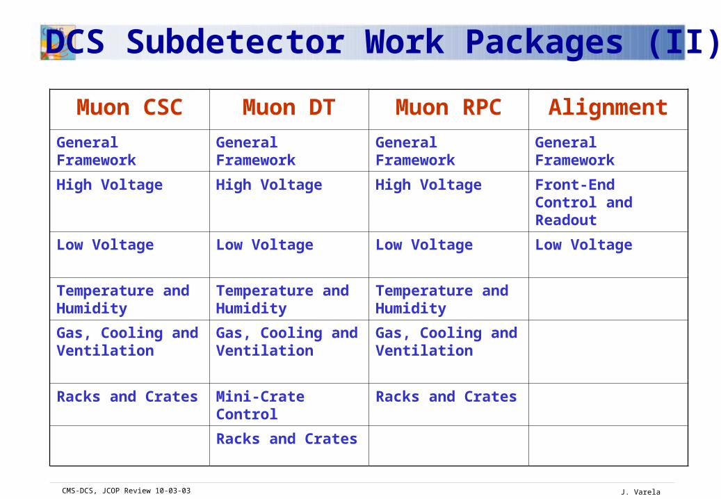
DCS Subdetector Work Packages (II)
Muon CSC Muon DT Muon RPC Alignment
General Framework General Framework General Framework General Framework
High Voltage High Voltage High Voltage Front-End Control and Readout
Low Voltage Low Voltage Low Voltage Low Voltage
Temperature and Humidity
Temperature and Humidity
Temperature and Humidity
Gas, Cooling and Ventilation
Gas, Cooling and Ventilation
Gas, Cooling and Ventilation
Racks and Crates Mini-Crate Control Racks and Crates
Racks and Crates

CMS-DCS, JCOP Review 10-03-03 J. Varela
2Q 3Q 4Q 1Q 2Q 3Q 4Q 1Q 2Q 3Q 4Q 1Q 2Q 3Q 4Q
TrackerGeneral FrameworkHigh voltageLow voltageDCU MonitoringTemperature, HumidityThermal screenInterlock control
ECALGeneral FrameworkHigh voltageLow voltageTemperature, HumidityTSSCoolingLaserPreshower
HCALGeneral FrameworkHigh voltageLow voltageReadout BoxesSource calibration LaserHF radiation monitoring
DTGeneral FrameworkHigh voltageLow voltageTemperature, HumidityGas and coolingMini-crate control
RPCGeneral FrameworkHigh voltageLow voltageTemperature, HumidityGas and coolingFront-end control
2006DCS MilestonesSub-detectors
2003 2004 2005
Subdetector DCS Milestones
First Prototype using PVSS framework
First Integration with Central DCS
Final System

CMS-DCS, JCOP Review 10-03-03 J. Varela
DCS Conventions and Interfaces Q2 03Naming scheme, Commands, States
Data Bases Specification Q3 03 Configuration, Conditions, Assets, Archive
Prototype Central DCS Q4 03 Including scaling tests
First prototype of complete DCS system Q4 04Integration of subdetectors (Slice test)Configuration DataBaseDAQ interface
Integration with Dedicated SystemsGas, Cooling, Racks, DSS Q1 05Magnet, Technical services Q1 06
Central DCS Milestones

CMS-DCS, JCOP Review 10-03-03 J. Varela
Requirements to JCOPHierarchy Control (2Q 2003)
Configuration Tools (2Q 2003)
HV Control (2Q 2003)
Detector Safety System (1Q 2004)
Data visualisation (1Q 2004)
Crate Control (1Q 2004)
Rack Control (1Q 2004)
Interface to Conditions Data Base (2Q 2004)
Large scale distribution system (2Q 2004)
Gas Control (4Q 2004)
Cooling and Ventilation Control (4Q 2004)
Web Access (4Q 2005)
Interface to Technical Services (1Q 2006)
Interface to LHC Accelerator (2Q 2006)