Overview 18-759: Wireless Networks Lecture 19: LTEprs/wirelessS16/handouts/L19-Cellular.pdf ·...
15
Page 1 Peter A. Steenkiste, CMU 1 18-759: Wireless Networks Lecture 19: LTE Peter Steenkiste Departments of Computer Science and Electrical and Computer Engineering Spring Semester 2016 http://www.cs.cmu.edu/~prs/wirelessS16/ Peter A. Steenkiste, CMU 2 Overview Motivation Architecture Resource management LTE protocols Radio access network » OFDM refresher LTE advanced Some slides based on material from “Wireless Communication Networks and Systems” © 2016 Pearson Higher Education, Inc. Peter A. Steenkiste, CMU 3 4G Technology High-speed, universally accessible wireless service capability Creating a revolution » Networking at all locations for tablets, smartphones, computers, and other devices » Similar to the revolution caused by Wi-Fi Our focus is LTE and LTE-Advanced » Goals and requirements, complete system architecture, core network (Evolved Packet System), LTE channel and physical layer » Will first study LTE Release 8, then enhancements from Releases 9-12 Peter A. Steenkiste, CMU 4 Purpose, motivation, and approach to 4G Ultra-mobile broadband access » For a variety of mobile devices International Telecommunication Union (ITU) 4G directives for IMT-Advanced » All-IP packet switched network. » Peak data rates – Up to 100 Mbps for high-mobility mobile access – Up to 1 Gbps for low-mobility access » Dynamically share and use network resources » Smooth handovers across heterogeneous networks, including 2G and 3G networks, small cells such as picocells, femtocells, and relays, and WLANs » High quality of service for multimedia applications
-
Upload
trinhduong -
Category
Documents
-
view
218 -
download
4
Transcript of Overview 18-759: Wireless Networks Lecture 19: LTEprs/wirelessS16/handouts/L19-Cellular.pdf ·...
Page 1
Peter A. Steenkiste, CMU 1
18-759: Wireless NetworksLecture 19: LTE
Peter SteenkisteDepartments of Computer Science andElectrical and Computer Engineering
Spring Semester 2016http://www.cs.cmu.edu/~prs/wirelessS16/
Peter A. Steenkiste, CMU 2
Overview
Motivation Architecture Resource management LTE protocols Radio access network
» OFDM refresher
LTE advanced
Some slides based on material from “Wireless Communication Networks and Systems”© 2016 Pearson Higher Education, Inc.
Peter A. Steenkiste, CMU 3
4G Technology
High-speed, universally accessible wireless service capability
Creating a revolution» Networking at all locations for tablets, smartphones,
computers, and other devices» Similar to the revolution caused by Wi-Fi
Our focus is LTE and LTE-Advanced» Goals and requirements, complete system architecture,
core network (Evolved Packet System), LTE channel and physical layer
» Will first study LTE Release 8, then enhancements from Releases 9-12
Peter A. Steenkiste, CMU 4
Purpose, motivation, and approach to 4G
Ultra-mobile broadband access» For a variety of mobile devices
International Telecommunication Union (ITU) 4G directives for IMT-Advanced
» All-IP packet switched network.» Peak data rates
– Up to 100 Mbps for high-mobility mobile access– Up to 1 Gbps for low-mobility access
» Dynamically share and use network resources» Smooth handovers across heterogeneous networks, including 2G
and 3G networks, small cells such as picocells, femtocells, and relays, and WLANs
» High quality of service for multimedia applications

Page 2
Peter A. Steenkiste, CMU 5
High Level Context
No support for circuit-switched voice» Instead providing Voice over LTE (VoLTE)
Replace spread spectrum with OFDM
Peter A. Steenkiste, CMU 6
3G versus 4G
Peter A. Steenkiste, CMU 7
LTE Architecture
Two candidates for 4G» IEEE 802.16 WiMax (described in Chapter 16)
– Enhancement of previous fixed wireless standard for mobility
» Long Term Evolution– Third Generation Partnership Project (3GPP)– Consortium of Asian, European, and North American
telecommunications standards organizations
Both are similar in use of OFDM and OFDMA LTE has become the universal standard for 4G
» All major carriers in the United States» WiMax is now mostly for fixed backhaul, last mile in rural
areas, …
Peter A. Steenkiste, CMU 8
WiMAX vs. LTEDiscussion
WiMAX first to market WiMAX is IEEE standard – equipment cheaper
» E.g., more emphasis on TDD, which is easier
LTE out of GSM, with a great install base already!
All 3GPP operators already have spectrum that can be used for LTE – not true for WiMAX
802.16m (in 2009) comparable speeds to LTE
Page 3
Peter A. Steenkiste, CMU 9
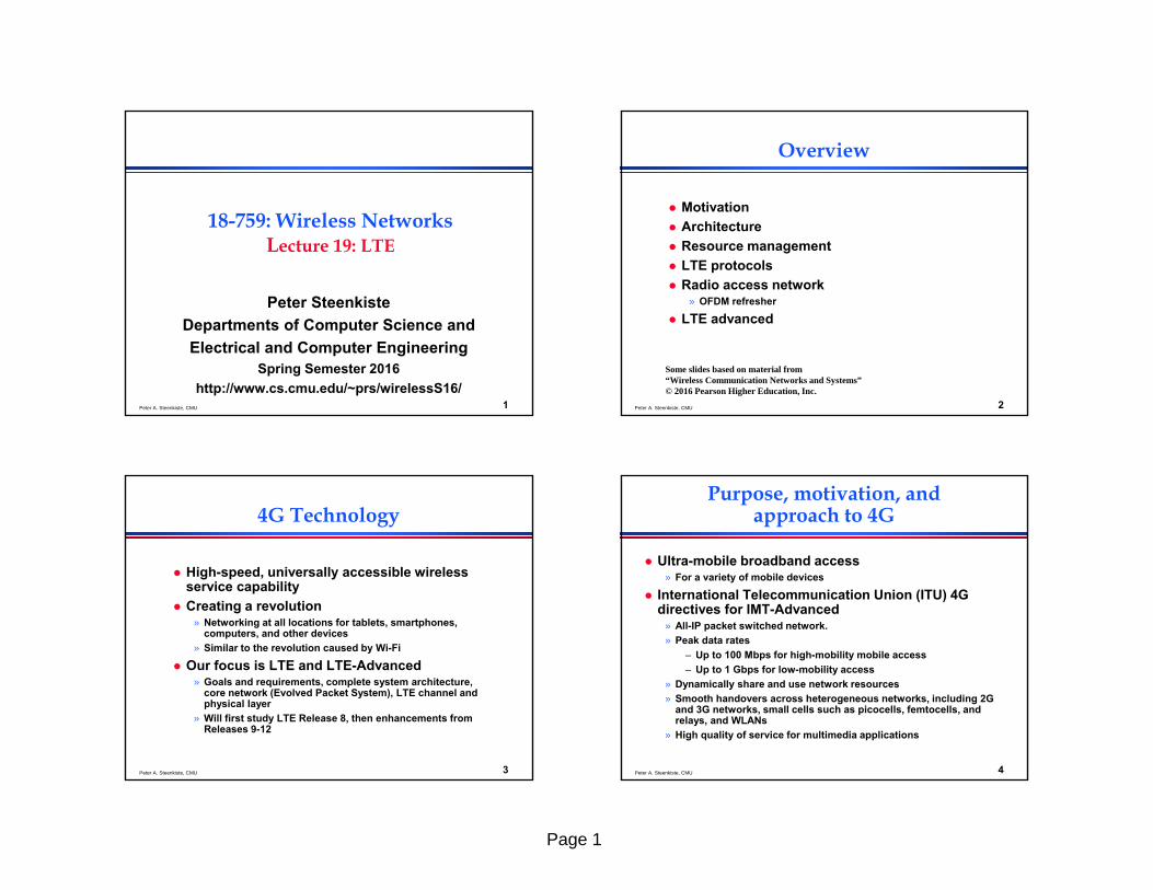
Comparison LTE and LTE-Advanced
Peter A. Steenkiste, CMU 10
Overview
Motivation Architecture Resource management LTE protocols Radio access network
» OFDM refresher
LTE advanced
Some slides based on material from “Wireless Communication Networks and Systems”© 2016 Pearson Higher Education, Inc.
Peter A. Steenkiste, CMU 11
LTE Architecture
evolved NodeB (eNodeB)» Most devices connect into the
network through the eNodeB Evolution of the previous
3GPP NodeB» Now based on OFDMA instead of
CDMA» Has its own control functionality,
rather than using the Radio Network Controller (RNC)
– eNodeB supports radio resource control, admission control, and mobility management
– Originally the responsibility of the RNC
Radio AccessNetwork
CoreNetwork
Peter A. Steenkiste, CMU 12
Evolved Packet System
Overall architecture is called the Evolved Packet System (EPS)
3GPP standards divide the network into» Radio access network (RAN)» Core network (CN)
Each evolve independently. Long Term Evolution (LTE) is the RAN
» Called Evolved UMTS Terrestrial Radio Access (E-UTRA)» Enhancement of 3GPP’s 3G RAN
– Called the Evolved UMTS Terrestrial Radio Access Network (E-UTRAN)
» eNodeB is the only logical node in the E-UTRAN» No RNC
Page 4
Peter A. Steenkiste, CMU 13
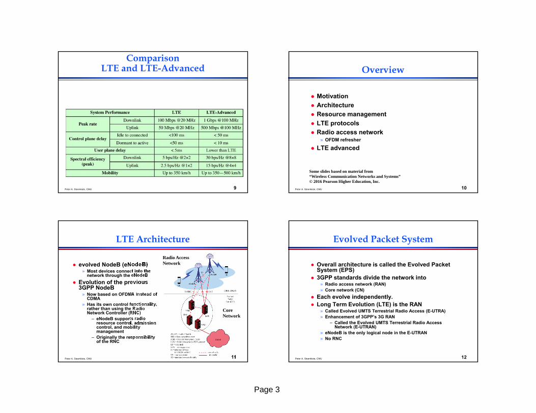
Evolved Packet System
Evolved Packet Core (EPC)» Operator or carrier core network –core of the system
Traditionally circuit switched but now entirely packet switched
» Based on IP - Voice supported using voice over IP (VoIP) Some of the design principles of the EPS
» Packet-switched transport for traffic belonging to all QoS classes including conversational, streaming, real-time, non-real-time, and background
» Radio resource management: end-to-end QoS, transport for higher layers, load sharing/balancing, policy management across different radio access technologies
» Integration with existing 3GPP 2G and 3G networks» Scalable bandwidth from 1.4 MHz to 20 MHz» Carrier aggregation for overall bandwidths up to 100 MHz
Peter A. Steenkiste, CMU 14
EPS Functions
Network access control, including network selection, authentication, authorization, admission control, policy and charging, and lawful interception
Packet routing and transfer Security, including ciphering, integrity protection, and
network interface physical link protection Mobility management to keep track of the current
location of the UE Radio resource management to assign, reassign, and
release radio resources taking into account single and multi-cell aspects
Network management (operation and maintenance) IP networking functions, connections of eNodeBs, E-
UTRAN sharing, emergency session support, etc.
Peter A. Steenkiste, CMU 15
EPC Components
Mobility Management Entity (MME)» Supports user equipment context, identity, authentication, and
authorization Serving Gateway (SGW)
» Receives and sends packets between the eNodeB and the core network
Packet Data Network Gateway (PGW)» Connects the EPC with external networks
Home Subscriber Server (HSS)» Database of user-related and subscriber-related information
Interfaces» S1 interface between the E-UTRAN and the EPC
– For both control purposes and for user plane data traffic» X2 interface for eNodeBs to interact with each other
– Again for both control purposes and for user plane data traffic
Peter A. Steenkiste, CMU 16
Overview
Motivation Architecture Resource management LTE protocols Radio access network
» OFDM refresher
LTE advanced
Some slides based on material from “Wireless Communication Networks and Systems”© 2016 Pearson Higher Education, Inc.

Page 5
Peter A. Steenkiste, CMU 17
LTE Resource Management
LTE uses bearers for quality of service (QoS) control instead of circuits
EPS bearers» Between PGW and UE» Maps to specific QoS parameters such as data rate, delay,
and packet error rate Service Data Flows (SDFs) differentiate traffic
flowing between applications on a client and a service
» SDFs must be mapped to EPS bearers for QoS treatment» SDFs allow traffic types to be given different treatment
End-to-end service is not completely controlled by LTE
Peter A. Steenkiste, CMU 18
LTE QoS Bearers
Peter A. Steenkiste, CMU 19
Bearer Management based on QoS Class Identifier
Guaranteed(minimum)
Bit Rate
NoGuarantees
Peter A. Steenkiste, CMU 20
Classes of bearers
Guaranteed Bit Rate (GBR) bearers» Guaranteed a minimum bit rate
– And possibly higher bit rates if system resources are available
» Useful for voice, interactive video, or real-time gaming
Non-GBR (GBR) bearers» Not guaranteed a minimum bit rate» Performance is more dependent on the number of UEs
served by the eNodeB and the system load» Useful for e-mail, file transfer, Web browsing, and P2P file
sharing.
Page 6
Peter A. Steenkiste, CMU 21
Bearer management
Each QCI is given standard forwarding treatments» Scheduling policy, admission thresholds, rate-shaping
policy, queue management thresholds, and link layer protocol configuration
For each bearer the following information is associated
» QoS class identifier (QCI) value» Allocation and Retention Priority (ARP): Used to decide if a
bearer request should be accepted or rejected Additionally for GBR bearers
» Guaranteed Bit Rate (GBR): minimum rate expected from the network
» Maximum Bit Rate (MBR): bit rate not to be exceeded from the UE into the bearer
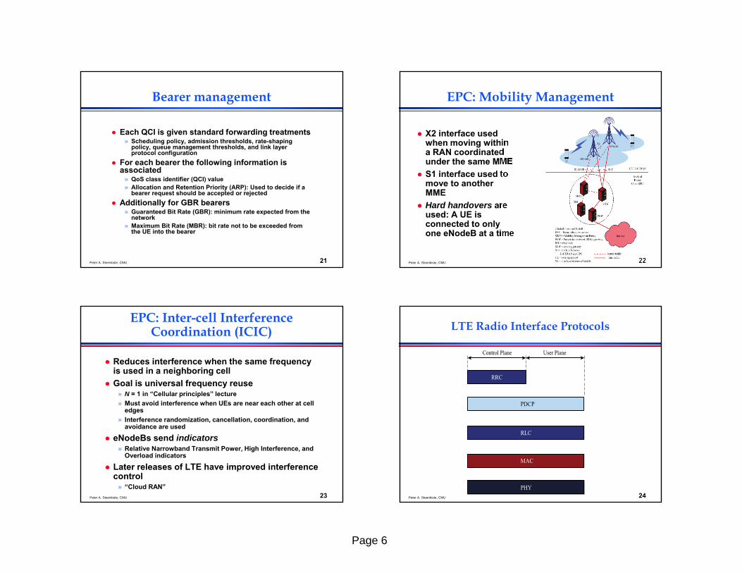
Peter A. Steenkiste, CMU 22
EPC: Mobility Management
X2 interface used when moving within a RAN coordinated under the same MME
S1 interface used to move to another MME
Hard handovers are used: A UE is connected to only one eNodeB at a time
Peter A. Steenkiste, CMU 23
EPC: Inter-cell Interference Coordination (ICIC)
Reduces interference when the same frequency is used in a neighboring cell
Goal is universal frequency reuse» N = 1 in “Cellular principles” lecture» Must avoid interference when UEs are near each other at cell
edges» Interference randomization, cancellation, coordination, and
avoidance are used
eNodeBs send indicators» Relative Narrowband Transmit Power, High Interference, and
Overload indicators
Later releases of LTE have improved interference control
» “Cloud RAN”Peter A. Steenkiste, CMU 24
LTE Radio Interface Protocols
Page 7
Peter A. Steenkiste, CMU 25
Overview
Motivation Architecture Resource management LTE protocols Radio access network
» OFDM refresher
LTE advanced
Some slides based on material from “Wireless Communication Networks and Systems”© 2016 Pearson Higher Education, Inc.
Peter A. Steenkiste, CMU 26
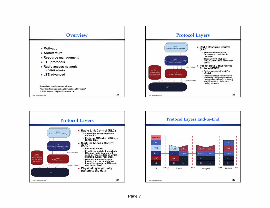
Protocol Layers
Radio Resource Control (RRC)
» Performs control plane functions to control radio resources
» Through RRC_IDLE and RRC_CONNECTED connection states
Packet Data Convergence Protocol (PDCP)
» Delivers packets from UE to eNodeB
» Involves header compression, ciphering, integrity protection, in-sequence delivery, buffering and forwarding of packets during handover
Peter A. Steenkiste, CMU 27
Protocol Layers
Radio Link Control (RLC)» Segments or concatenates
data units» Performs ARQ when MAC layer
H-ARQ fails Medium Access Control
(MAC)» Performs H-ARQ» Prioritizes and decides which
UEs and radio bearers will send or receive data on which shared physical resources
» Decides the transmission format, i.e., the modulation format, code rate, MIMO rank, and power level
Physical layer actually transmits the data
Peter A. Steenkiste, CMU 28
Protocol Layers End-to-End
Page 8
Peter A. Steenkiste, CMU 29
LTE Channel Structure usesThree Types of Channels
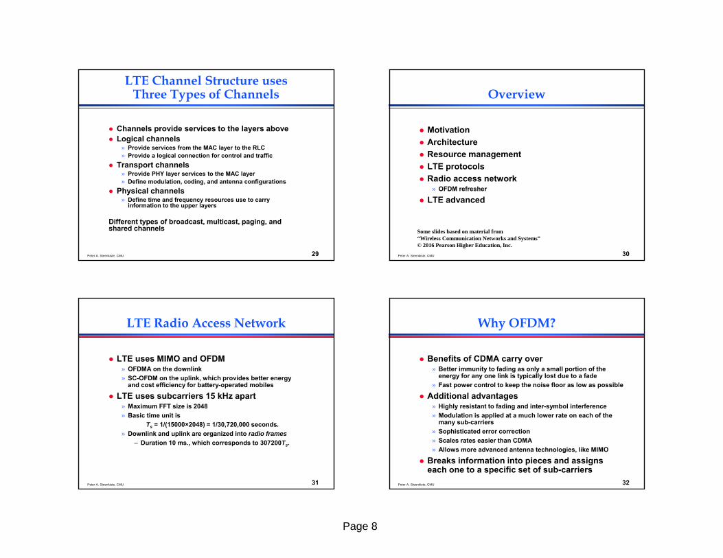
Channels provide services to the layers above Logical channels
» Provide services from the MAC layer to the RLC» Provide a logical connection for control and traffic
Transport channels» Provide PHY layer services to the MAC layer» Define modulation, coding, and antenna configurations
Physical channels» Define time and frequency resources use to carry
information to the upper layers
Different types of broadcast, multicast, paging, and shared channels
Peter A. Steenkiste, CMU 30
Overview
Motivation Architecture Resource management LTE protocols Radio access network
» OFDM refresher
LTE advanced
Some slides based on material from “Wireless Communication Networks and Systems”© 2016 Pearson Higher Education, Inc.
Peter A. Steenkiste, CMU 31
LTE Radio Access Network
LTE uses MIMO and OFDM» OFDMA on the downlink» SC-OFDM on the uplink, which provides better energy
and cost efficiency for battery-operated mobiles
LTE uses subcarriers 15 kHz apart» Maximum FFT size is 2048» Basic time unit is
Ts = 1/(15000×2048) = 1/30,720,000 seconds. » Downlink and uplink are organized into radio frames
– Duration 10 ms., which corresponds to 307200Ts.
Peter A. Steenkiste, CMU 32
Why OFDM?
Benefits of CDMA carry over» Better immunity to fading as only a small portion of the
energy for any one link is typically lost due to a fade» Fast power control to keep the noise floor as low as possible
Additional advantages» Highly resistant to fading and inter-symbol interference» Modulation is applied at a much lower rate on each of the
many sub-carriers» Sophisticated error correction» Scales rates easier than CDMA» Allows more advanced antenna technologies, like MIMO
Breaks information into pieces and assigns each one to a specific set of sub-carriers

Page 9
Peter A. Steenkiste, CMU 33
Example
Peter A. Steenkiste, CMU 34
OFDM Key Points
OFDM signals best described in the frequency domain with information carried in the amplitude and the phase
» Conversion to the time domain through Inverse Fast Fourier Transform (IFFT)
» Demodulation through Fast Fourier Transform (FFT)
Guard interval protects against inter-symbol interference caused by multi-path reception over path delays up to the length of the guard interval
» Guard interval is a cyclic prefix (CP in LTE)» A copy of the end of a symbol is added at the beginning» Helps fight multipath
Peter A. Steenkiste, CMU 35
Robustness to ISI
If time-sampling of the symbol is within the useful part, equalizers can take care of the path delay and the second path can be combined with the first to
increase the probability of correct reception Peter A. Steenkiste, CMU 36
Other benefits
OFDM channel equalizers are much simpler to implement than are CDMA equalizers as the OFDM signal is represented in the frequency domain rather than the time domain
OFDM is better suited to MIMO. The frequency domain representation of the signal enables easy pre-coding to match the signal to frequency and phase characteristics of the multipath radio channel
Page 10
Peter A. Steenkiste, CMU 37
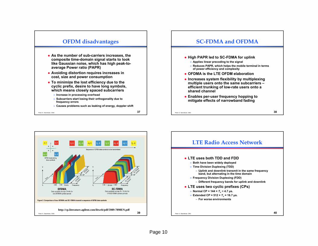
OFDM disadvantages
As the number of sub-carriers increases, the composite time-domain signal starts to look like Gaussian noise, which has high peak-to-average Power ratio (PAPR)
Avoiding distortion requires increases in cost, size and power consumption
To minimize the lost efficiency due to the cyclic prefix, desire to have long symbols, which means closely spaced subcarriers
» Increase in processing overhead» Subcarriers start losing their orthogonality due to
frequency errors» Causes problems such as leaking of energy, doppler shift
Peter A. Steenkiste, CMU 38
SC-FDMA and OFDMA
High PAPR led to SC-FDMA for uplink» Applies linear precoding to the signal» Reduces PAPR, which helps the mobile terminal in terms
of power efficiency and complexity
OFDMA is the LTE OFDM elaboration Increases system flexibility by multiplexing
multiple users onto the same subcarriers –efficient trunking of low-rate users onto a shared channel
Enables per-user frequency hopping to mitigate effects of narrowband fading
Peter A. Steenkiste, CMU 39http://cp.literature.agilent.com/litweb/pdf/5989-7898EN.pdf
Peter A. Steenkiste, CMU 40
LTE Radio Access Network
LTE uses both TDD and FDD» Both have been widely deployed» Time Division Duplexing (TDD)
– Uplink and downlink transmit in the same frequency band, but alternating in the time domain
» Frequency Division Duplexing (FDD)– Different frequency bands for uplink and downlink
LTE uses two cyclic prefixes (CPs)» Normal CP = 144 × Ts = 4.7 μs. » Extended CP = 512 × Ts = 16.7 μs.
– For worse environments

Page 11
Peter A. Steenkiste, CMU 41
Spectrum Allocation for FDD and TDD
Peter A. Steenkiste, CMU 42
FDD Frame Structure
Peter A. Steenkiste, CMU 43
TDD Frame Structure
Peter A. Steenkiste, CMU 44
Resource Blocks
A time-frequency grid is used to illustrate allocation of physical resources
Each column is 6 or 7 OFDM symbols per slot
Each row corresponds to a subcarrier of 15 kHz
» Some subcarriers are used for guard bands
» 10% of bandwidth is used for guard bands for channel bandwidths of 3 MHz and above
Page 12
Peter A. Steenkiste, CMU 45
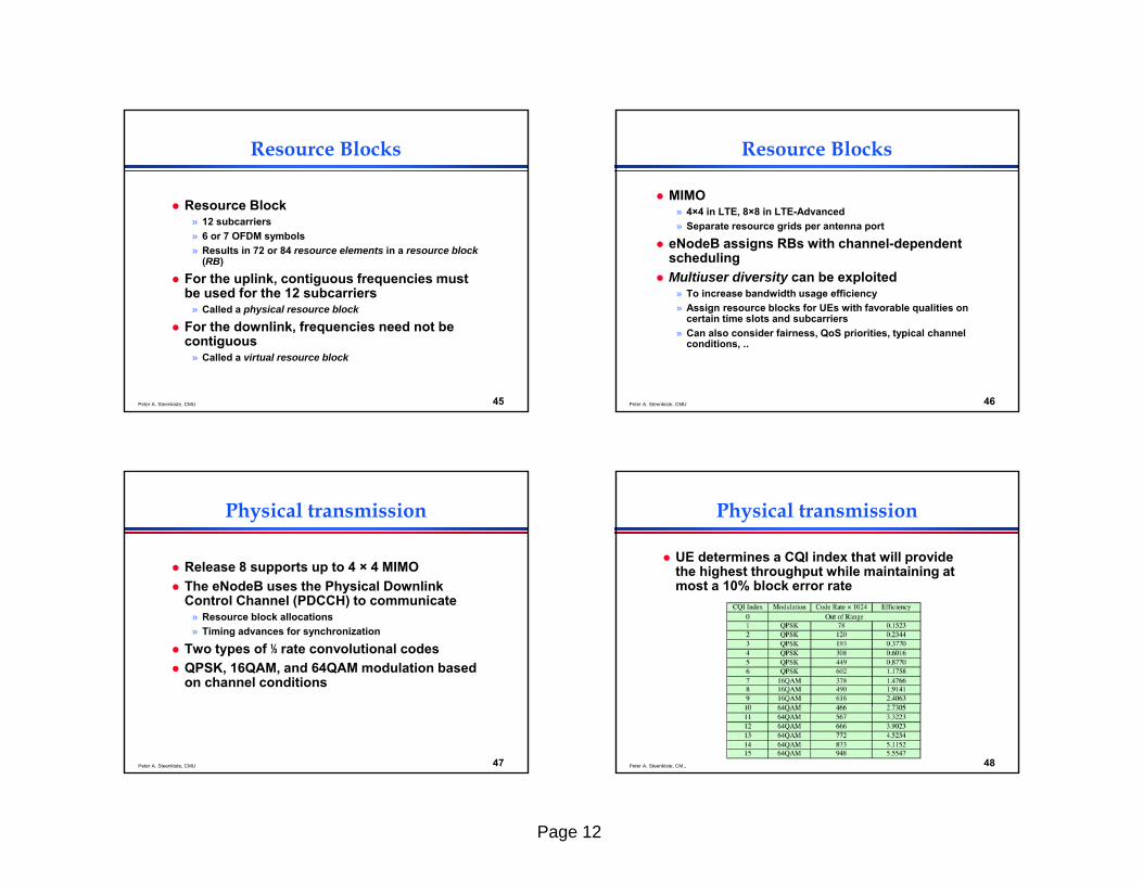
Resource Blocks
Resource Block» 12 subcarriers» 6 or 7 OFDM symbols» Results in 72 or 84 resource elements in a resource block
(RB)
For the uplink, contiguous frequencies must be used for the 12 subcarriers
» Called a physical resource block
For the downlink, frequencies need not be contiguous
» Called a virtual resource block
Peter A. Steenkiste, CMU 46
Resource Blocks
MIMO» 4×4 in LTE, 8×8 in LTE-Advanced» Separate resource grids per antenna port
eNodeB assigns RBs with channel-dependent scheduling
Multiuser diversity can be exploited» To increase bandwidth usage efficiency» Assign resource blocks for UEs with favorable qualities on
certain time slots and subcarriers» Can also consider fairness, QoS priorities, typical channel
conditions, ..
Peter A. Steenkiste, CMU 47
Physical transmission
Release 8 supports up to 4 × 4 MIMO The eNodeB uses the Physical Downlink
Control Channel (PDCCH) to communicate» Resource block allocations» Timing advances for synchronization
Two types of ⅓ rate convolutional codes QPSK, 16QAM, and 64QAM modulation based
on channel conditions
Peter A. Steenkiste, CMU 48
Physical transmission
UE determines a CQI index that will provide the highest throughput while maintaining at most a 10% block error rate

Page 13
Peter A. Steenkiste, CMU 49
Overview
Motivation Architecture Resource management LTE protocols Radio access network
» OFDM refresher
LTE advanced
Some slides based on material from “Wireless Communication Networks and Systems”© 2016 Pearson Higher Education, Inc.
Peter A. Steenkiste, CMU 50
LTE-Advanced
Carrier aggregation MIMO enhancements to support higher
dimensional MIMO Relay nodes Heterogeneous networks involving small cells
such as femtocells, picocells, and relays Cooperative multipoint transmission and
enhanced intercell interference coordination Voice over LTE
Peter A. Steenkiste, CMU 51
Carrier Aggregation
Ultimate goal of LTE-Advanced is 100 MHz bandwidth
» Combine up to 5 component carriers (CCs)
» Each CC can be 1.4, 3, 5, 10, 15, or 20 MHz
» Up to 100 MHz Three approaches to combine
CCs» Intra-band Contiguous: carriers
adjacent to each other» Intra-band noncontiguous: Multiple
CCs belonging to the same band are used in a noncontiguous manner
» Inter-band noncontiguous: Use different bands
Peter A. Steenkiste, CMU 52
Enhanced MIMO
Expanded to 8 × 8 for 8 parallel layers Or multi-user MIMO can allow up to 4 mobiles
to receive signals simultaneously» eNodeB can switch between single user and multi-user
every subframe
Downlink reference signals to measure channels are key to MIMO functionality
» UEs recommend MIMO, precoding, modulation, and coding schemes
» Reference signals sent on dynamically assigned subframes and resource blocks
Page 14
Peter A. Steenkiste, CMU 53
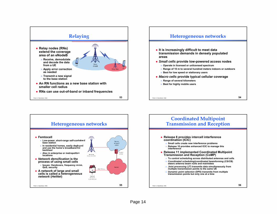
Relaying
Relay nodes (RNs) extend the coverage area of an eNodeB
» Receive, demodulate and decode the data from a UE
» Apply error correction as needed
» Transmit a new signal to the base station
An RN functions as a new base station with smaller cell radius
RNs can use out-of-band or inband frequencies
Peter A. Steenkiste, CMU 54
Heterogeneous networks
It is increasingly difficult to meet data transmission demands in densely populated areas
Small cells provide low-powered access nodes» Operate in licensed or unlicensed spectrum» Range of 10 m to several hundred meters indoors or outdoors» Best for low speed or stationary users
Macro cells provide typical cellular coverage» Range of several kilometers» Best for highly mobile users
Peter A. Steenkiste, CMU 55
Heterogeneous networks
Femtocell» Low-power, short-range self-contained
base station» In residential homes, easily deployed
and use the home’s broadband for backhaul
» Also in enterprise or metropolitan locations
Network densification is the process of using small cells
» Issues: Handovers, frequency reuse, QoS, security
A network of large and small cells is called a heterogeneous network (HetNet)
Peter A. Steenkiste, CMU 56
Coordinated Multipoint Transmission and Reception
Release 8 provides intercell interference coordination (ICIC)
» Small cells create new interference problems» Release 10 provides enhanced ICIC to manage this
interference Release 11 implemented Coordinated Multipoint
Transmission and Reception (CoMP)» To control scheduling across distributed antennas and cells» Coordinated scheduling/coordinated beamforming (CS/CB)
steers antenna beam nulls and mainlobes» Joint processing (JT) transmits data simultaneously from
multiple transmission points to the same UE» Dynamic point selection (DPS) transmits from multiple
transmission points but only one at a time

Page 15
Peter A. Steenkiste, CMU 57
Other Enhancements inLTE-Advanced
Traffic offload techniques to divert traffic onto non-LTE networks
Adjustable capacity and interference coordination
Enhancements for machine-type communications
Support for dynamic adaptation of TDD configuration so traffic fluctuations can be accommodated
Peter A. Steenkiste, CMU 58
Voice over LTE
The GSM Association is the cellular industry’s main trade association
» GSM Association documents provide additional specifications for issues that 3GPP specifications left as implementation options.
Defined profiles and services for Voice over LTE (VoLTE)
Uses the IP Multimedia Subsystem (IMS) to control delivery of voice over IP streams
» IMS is not part of LTE, but a separate network» IMS is mainly concerned with signaling.
The GSM Association also specifies services beyond voice, such as video calls, instant messaging, chat, and file transfer in what is known as the Rich Communication Services (RCS).