Overhead-Wire-Free Light Rail Systemsdocs.trb.org/prp/11-1332.pdfMargarita Novales 1 Overhead wires...
16
Margarita Novales 1 Overhead wires free light rail systems Submission date: July 29, 2010. Number of words: 5999. Number of tables: 1 Number of figures: 5 Equivalent number of words: 5999+6·250 = 7499 words. Corresponding author: Margarita Novales. Authors: Margarita Novales. Civil Engineer, PhD. Railways Associate Professor. La Coruña University. Address: ETS Ingenieros de Caminos, Canales y Puertos. Campus de Elviña, s/n. E-15071. A Coruña. Spain Telephone: +(34)981167000 Ext.:1452 Fax: +(34)981167170 E-mail: [email protected] TRB 2011 Annual Meeting Paper revised from original submittal.
Transcript of Overhead-Wire-Free Light Rail Systemsdocs.trb.org/prp/11-1332.pdfMargarita Novales 1 Overhead wires...
Margarita Novales 1
Overhead wires free light rail systems
Submission date: July 29, 2010.
Number of words: 5999.
Number of tables: 1
Number of figures: 5
Equivalent number of words: 5999+6·250 = 7499 words.
Corresponding author: Margarita Novales.
Authors:
Margarita Novales. Civil Engineer, PhD. Railways Associate Professor. La Coruña University.
Address: ETS Ingenieros de Caminos, Canales y Puertos. Campus de Elviña, s/n. E-15071. A Coruña.
Spain
Telephone: +(34)981167000 Ext.:1452
Fax: +(34)981167170
E-mail: [email protected]
TRB 2011 Annual Meeting Paper revised from original submittal.
Margarita Novales 2
ABSTRACT
Light rail systems are experiencing a revival in several countries in the world. Nevertheless, they are
facing a more and more demanding market which implies continuous new evolutions and technologies.
An example of this fact is related to the requirement of avoiding visual intrusion in some areas of cities
which are more sensitive to visual impact.
This fact has led to the implementation of new solutions that try to avoid the need for overhead
contact wires through the whole network or through the lengths between stations. These solutions are
based, generally, in the use of new embedded third-rail systems; the use of on-board energy storage
devices; or the use of electric energy produced on-board the vehicle.
This paper is focused in the explanation of these technologies, their applicability, as well as their
advantages, risks and inconveniences, in an attempt to clarify available options and their reliability.
1 INTRODUCTION
Although streetcars disappeared in many cities around the middle of the last century, nowadays a revival
of this technology is taking place, in most cases improving the performance of the system by the use of
type B right of way category [1], that is, giving to transit a longitudinally physically separated right of
way, which will improve operational speed, frequencies, availability and punctuality of the system.
Several countries can be cited as examples of this revival, such as Spain, France and the United States.
Nevertheless, nowadays light rail systems are facing a new requirement related to environmental
impact, specifically to the visual intrusion produced by overhead contact system (OCS). OCS typically
consists of vertical support poles located either on the center of the track, or on one or both of its sides,
from which the isolators and the wires which provide electric power to the vehicles are suspended.
Electrical energy is transferred from the overhead wire to the vehicle by a roof-mounted pantograph [2].
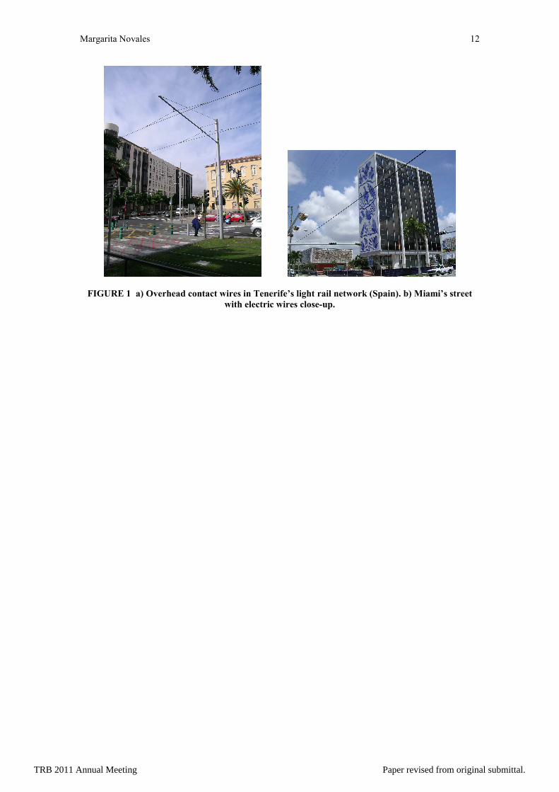
It is true that in most cases OCS should not be an important environmental problem, because the
solutions usually provided for urban systems (speeds up to 70 km/h), consists only of one contact wire
suspended directly from the poles, or by means of a short auxiliary wire. If this disposition is compared
with the initial state of many streets (see Figure 1), it is clear that the effect of OCS will be at most similar
to the one of the electrical cables existing in many cases.
On the other hand, there are several measures to minimize the negative visual effect of OCS,
which are very well explained in [3].
Nevertheless, there will be some situations in which special care must be taken in relation to
visual intrusion. This is the case of areas with high significance, as historic city centers, emblematic
places of a metropolitan area, parkways, etc. In addition, there are some other locations in which the
existence of OCS may cause problems, as when a light rail route travels under bridges without vertical
clearance to allow OCS installation, or in places where it is difficult to install wires, as in tunnels or at
large intersections. There are even some cities in whose centre the use of aerial wires is forbidden (as is
the case of some areas of Washington DC).
Finally, OCS normally uses the track rails as a return circuit for electric power to the substations.
This fact may lead to stray currents, a phenomenon by which the return current follows the least resistant
path to earth instead of the rails. In the case of soil and ferrous objects stray currents cause an electrolytic
effect which can rapidly corrode any electrically conducting objects and in severe cases can lead to
structural failure. To prevent this from happening, important isolation measures must be taken, which can
raise construction costs of light rail systems.
Through the history of trams several cases of OCS-free systems have been implemented, as it is
the case, for example, of New York and Washington DC. These solutions were the result of a possibly
overzealous desire by these cities to eliminate all exposed wiring in the downtown districts. It resulted in
an installation that was not only much more problem-prone than OCS, but it also was more costly to
construct, maintain, and operate [4].
Nowadays, mentioned reasons have led several streetcar manufacturers to search for new
solutions to provide electric power for the streetcar vehicles. In many cases these solutions are quite
similar to the ancient ones, although they are improved in several aspects. They can either be combined
with OCS on different stretches of the network, or substitute OCS in the whole track.
These new solutions will be presented in this paper.
2 EXISTING SOLUTIONS FOR OCS-FREE LIGHT RAIL SYSTEMS
There are, mainly, three alternatives to prevent the use of contact wires in light rail systems with right of
way categories C (shared) and B (reserved) [1], which are the following:
TRB 2011 Annual Meeting Paper revised from original submittal.
Margarita Novales 3
• The use of an embedded third rail (ETR), located between the running rails at the same level
as the rest of the street. The traction power supply can be either by contact or inductive. In
any case, as the right of way can be utilized, at least in some areas, by other street users
(pedestrians, cyclist, private cars), safety must be guaranteed. This is achieved by allowing
that only the areas of the ETR which are under the vehicle be energized.
• Energy storage on-board the vehicle, by means of batteries, super-capacitors, flywheels, etc.
These elements will have to be charged either during the vehicle circulation, or when it is
stopped at stations.
• Electric energy produced on-board the vehicle, by means of diesel-electric generators, fuel-
cells, etc.
These technologies will be explained in the next sections.
2.1 Embedded third rail (ETR) technology
This technology is the only one that means a real alternative to OCS if elimination of wires along the
whole network is desired. Nevertheless, existing implementations do usually not affect the whole
networks, but are combined with OCS, using the ETR solution only in sensitive areas.
General advantages of this solution are:
• Preservation of the urban visual environment.
• Total safety for pedestrians and road users.
• Avoidance of access problems for emergency vehicles (as firefighters) to building facades.
• Prevention of conflicts with arboreal vegetation of the streets.
On the other hand, there are still some inconveniences in this solution, which are supposed to be
counteracted with time and experience, as the concerns about its operation with rain, ice and salt; the
construction and maintenance costs; and the reliability of the system.
Nowadays, there are three different ETR technologies, designed by three different companies,
with their corresponding patents and with different levels of development.
2.1.1 Alstom’ APS system
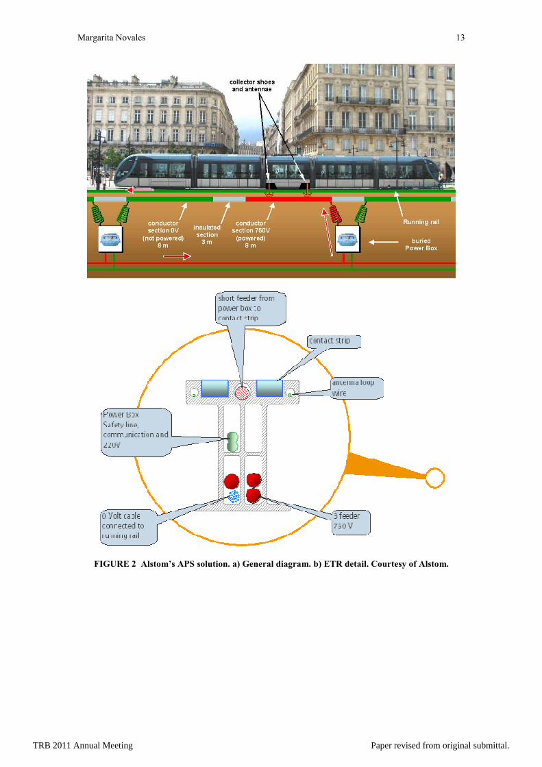
In this solution, the 750 V-dc ETR is made up of 8 m long conducting segments separated by 3 m insulating joints. Power is supplied to the conducting segments by underground boxes every 22 m.
The delivery of power to the conducting segments is triggered by coded radio dialogue between
the vehicle and the ground, and only occurs once the conducting segment has been covered by the tram,
ensuring total safety. The electricity transmitted through the ETR is picked up by two collector shoes
located in the mid-section of the tram, while a block of roof-mounted batteries allows the vehicle to
maintain power at stations or if a power control unit fails [5]. The whole system is shown in Figure 2.
Bordeaux (France) is the first city in the world to have opted for this completely new technology
on 14 km of its 44 km long tram network. It has been operating since the end of 2003 [5].
This solution had some initial troubles, due to drainage problems in buried power boxes. These
troubles were solved and APS is now operating successfully in Bordeaux at 99.8% reliability since the
end of 2005. Three other French cities, Angers, Reims and Orléans, decided in 2006 to install APS on
their new light rail networks, and Alstom won its first contract for a system outside Europe last year
(Dubai's Al Safooh Tramway) [5].
The main advantages of this solution, apart from the general ones of ETR solutions, are:
• It is a mature technology that has been proved in actual applications (initial problems
properly solved).
• Performance levels equal to those of a conventional tram in terms of comfort and speed.
The greater inconvenience of this technology, as of all ETR solutions, is related to the
infrastructure’s cost. Indeed, in the existing implementation the cost of each meter of APS system is
around 7 times the cost of the equivalent OCS. Nevertheless, it is important to note that OCS usually
represents only around 3% of the whole cost of a tramway project. If APS is applied in the most sensitive
zones (for example, 30% of the network, as is the case of Bordeaux), it will lead to an increase of project’
cost around 7·3·0.30=6.3%, which seems to be an affordable amount in a project of these characteristics.
For French applications, Bordeaux is the one with a greater percentage of APS in relation to the length of
the network. Only the Dubai project is going to have the complete network provided with APS.
APS leads to an increase of vehicle weight of around 1000 kg, which is not very significant. But
the ability to regenerate energy into the power distribution system is no longer possible. Therefore the
vehicle has to either store the energy locally or dissipate it into a brake resistor which must also be carried
TRB 2011 Annual Meeting Paper revised from original submittal.
Margarita Novales 4
in the vehicle [6]. In relation to maintenance costs, Alstom assures that maintenance overcost due to APS
is marginal (less than 3%).
Finally, concern exists in relation to the potential for stray currents where the roadway is wet or
wet with a salt solution for snow clearing [2]. On the other hand, it is probable that extra care must be
taken in the case of extreme-weather cities, for avoiding the contact strip to suffer from ice and salt build-
up across the conductors.
2.1.2 Ansaldo’s TRAMWAVE system
The TramWave technology is quite similar to APS. Again, the power supply system consists of a 750 V-
dc third rail embedded in the permanent way, provided by a contact line that only energizes a small
section as the vehicle passes over it.
TramWave is the result of the technical evolution and adaptation to tram vehicles of STREAM
(Electric Power System with Magnetic Attraction) system, developed by Ansaldo more than ten years
ago, and successfully tested in Trieste’s tyre vehicles (Italy), specifically in hybrid buses.
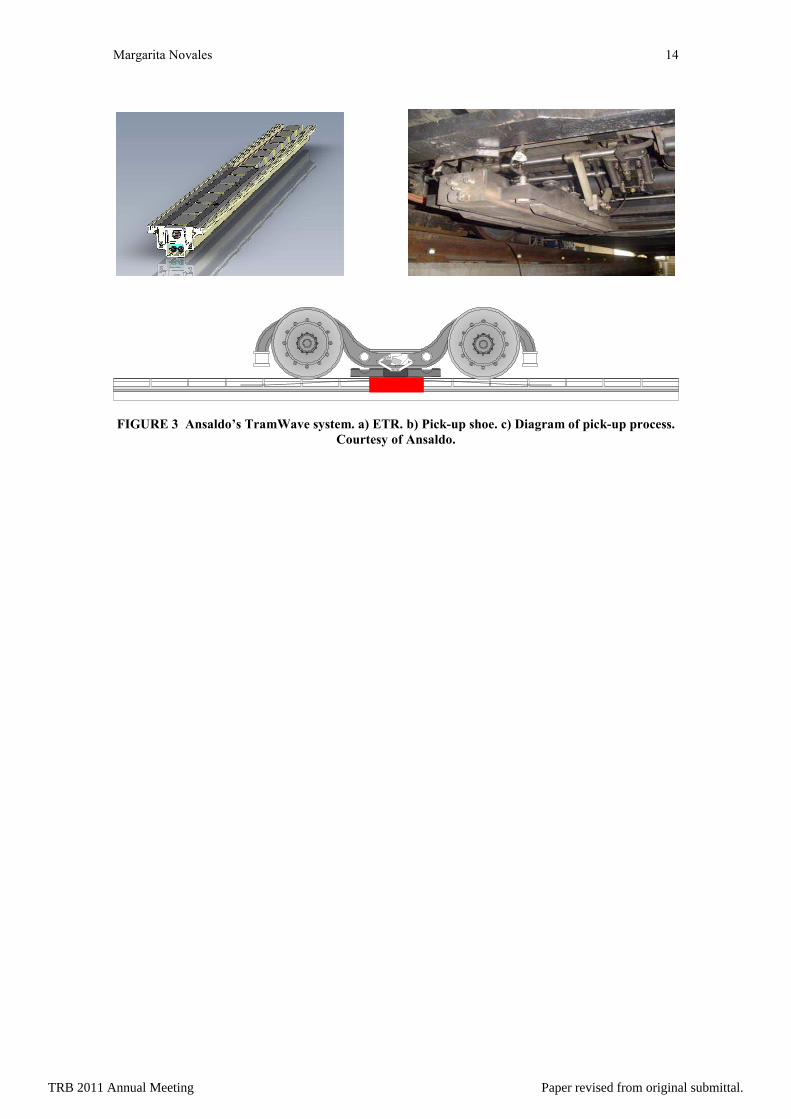
In this case, the basic building block of the TramWave system is a modular unit, 3 or 5 m long,
30 cm wide and 12 cm high, that contains all the elements needed for the correct functioning of the
ground-level power supply system.
A series of steel contact plates are located at intervals on the top of the box (see Figure 3). The
modular boxes are joined together to form the power supply of the light rail line. The modules are placed
in a “continuous conduit” that contains the positive feeder and a negative cable to protect the line.
The power collection is made by means of a retractable pickup shoe placed in the centre of
vehicle’s truck. It is equipped with hybrid magnets which attract the power element located at the bottom
of the module. The power element is flexible, in such a way that it can be elevated and when it is in
contact with the top part of the module the ETR segments in contact with the shoe are energized (see
Figure 3).
The system is designed in such a way that the energized length is not greater than 1.5 m (three
segments at the most), remaining always under the vehicle.
Ansaldo assures that this system has lower maintenance requirements than the OCS, because any
breakdown will affect only one module, which is automatically identified by the diagnosis system, and
can be replaced by another complete module in barely 30 minutes. In addition, the failure of one module
does not prevent the vehicles from running over the track, and the replacement can be made when the line
is in service.
TramWave can be commuted from overhead to ground supply, even when the vehicle is moving,
either automatically or by the driver’s order. In addition, it can be combined with on-board energy storage
systems, and the power supply can be used to recharge them. In the same way, the vehicle can be
disconnected from the supply line, even when it is moving, and run autonomously with energy stored on-
board.
An additional advantage of this system is the fact that the return current is transferred via the
contact plates and the tracks do not need to be used for this purpose. This is an important feature since in
this way the TramWave eliminates the effects of stray currents, avoiding the need for track electrical
isolation.
Finally, this power supply system can also be used by electrical vehicles which have rubber
tyres. Consequently, the tramway line equipped with the TramWave system can become the backbone
power line for different vehicle fleets and/or a global network that uses it as a mobile charging station for
battery-powered vehicles.
The main drawback of this system is that it has not been applied to any real system, although
tests for the feeding modules on the Naples (Italy) test track were successfully completed and there is now
an actual trial version of the system equipping 600 m of the Naples-Poggioreale experimental line.
Therefore, there are not enough data to make conclusions about cost and reliability of the system.
Finally, as for the case of Alstom’s APS solution, there is concern as to the potential for stray
currents where the roadway is wet or wet with a salt solution for snow clearing [2].
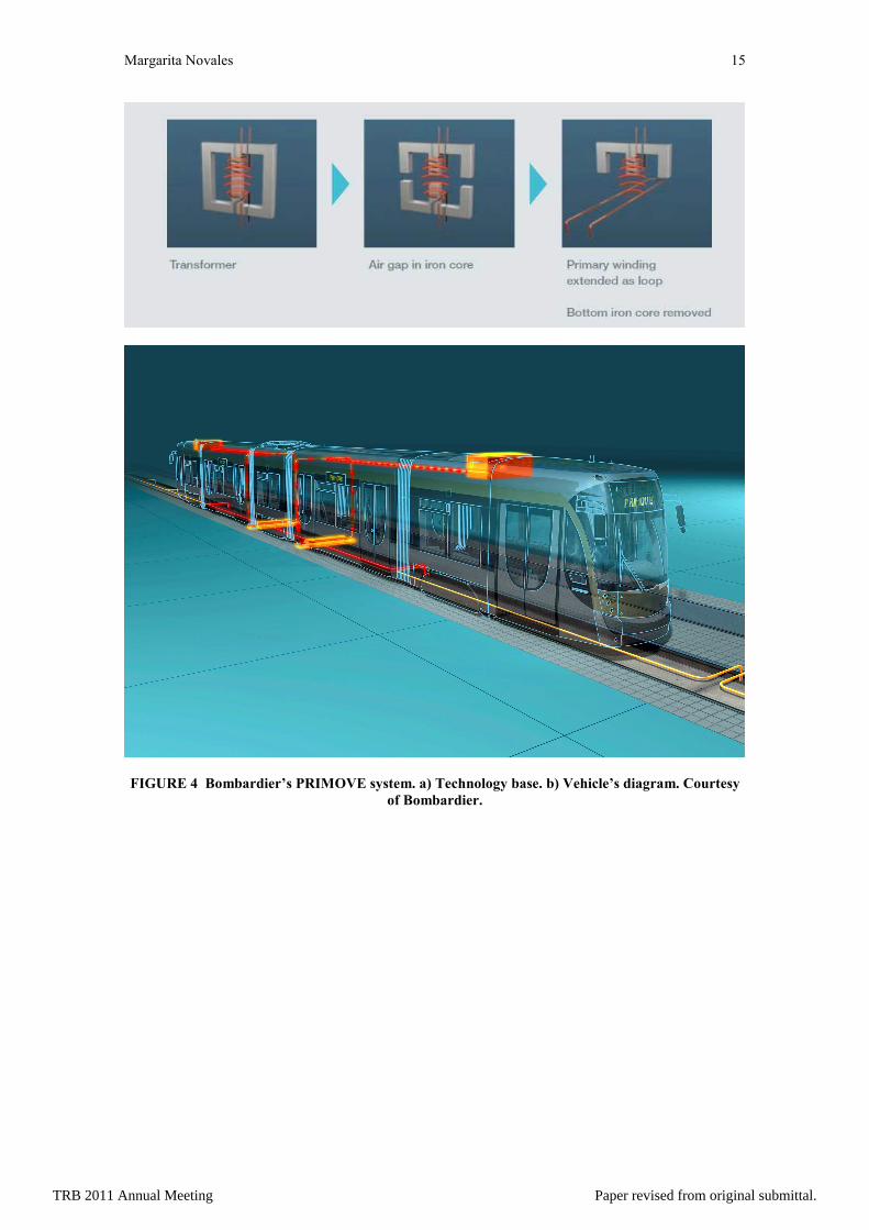
2.1.3 Bombardier’s PRIMOVE system
The PRIMOVE system is similar to APS and TramWave in some aspects, as that the wires laid beneath
the ground are connected to the power supply network, and are only energized when fully covered by the
vehicle.
Nevertheless, the technology for getting the energy from the ETR is very different, as it is based
on the inductive power transfer of a transformer (see Figure 4), without contact. While a magnetic field is
TRB 2011 Annual Meeting Paper revised from original submittal.
Margarita Novales 5
generated, energy is stored in the primary electric circuit, that is located between the rails of the track, and
the secondary circuit, under the vehicle, transforms this energy field in electric power for tram’s
operation.
In this case, to get the energy, a pick-up coil underneath the vehicle turns the magnetic field
created by the wires in the ground into an electric current that feeds the vehicle’s traction system.
This system is able to provide the energy needed for running up to 40 km/h over a 6% ramp.
Additionally, vehicles with PRIMOVE can be provided with the MITRAC energy saver
technology by Bombardier (see section 2.2.2).
PRIMOVE is undergoing extensive testing at the test track of the Bombardier site in Bautzen,
Germany, simulating regular operation. Additionally, Bombardier announced on May 2010 that
PRIMOVE is going to be tested in German Augsburg’s line 3 in a test branch 800 m long.
An important advantage of this system in relation to the two previously presented is that there is
no direct contact during energy transfer, and therefore, there is no wear of parts and components. This is
supposed to keep service and maintenance costs at a minimum.
On the other hand, Bombardier assures that this system is resistant to all weather and ground
conditions including storms, snow, ice, sand, rain and water, as well as that it gets the same vehicle
performance as with conventional OCS.
The main drawback is, as for the TramWave system, that it has not been tested yet in any real
application, although the results of the Augsburg test will be of interest to know more about its
performance. Bombardier assures that the initial construction costs lie far below those of any comparable
solution on the market, but it can not be contrasted until the Augsburg results are available.
Additionally, depending on the frequency of operation, the magnetic or inductive coupling may
also produce some local electromagnetic effects. On the other hand, this system has the same problem as
the Alstom’s one in which is related to energy regeneration [6].
2.2 Energy storage on-board the vehicle
The main disadvantage of ground power supply is, probably, that like in the case of OCS, it involves the
installation of fixed infrastructure, with the corresponding construction and maintenance costs, and the
additional problems to provide it to an existing network.
An alternative to these solutions is the use of on-board energy storage systems. These
technologies emerged, in the first stage, not in order to avoid the existence of overhead wires, but to
improve the energy efficiency of light rail systems.
Indeed, one way to reduce the energy consumption of trams is by using of regenerative braking,
which is widely extended in the railroad field, so as to make the most of the kinetics energy that has to be
dissipated during the braking process (that is very frequent in cities). But in the initial stages, for
regenerative braking to be effective, there had to be other vehicles around to absorb the surplus power
being fed back into the OCS, especially when traction is of dc type. Too often, power produced by
traction motors in braking mode ended up lost heating resistor banks.
To prevent this from happening, trams started to be provided with on-board energy storage
systems, in such a way that braking energy is saved for use when necessary due to points in the vehicle’s
demand, as is the case of acceleration. But very soon, the technicians were conscious of the additional
possibilities of this kind of technology to avoid the use of overhead wires in specific branches of the
network.
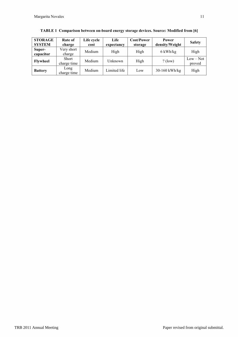
The most common technologies of on-board energy storage systems are batteries and, most
recently, super-capacitors. Other systems, as flywheels, have been used in some vehicles but they do not
seem to be a solid option. It can be due to the risk implied by having high speed rotating machinery in
close proximity with passengers, as well as to the flywheel’s concentrated weight and inertia. In any case,
perhaps further study of flywheels might be warranted because of their excellent charge/discharge cycle
life, even though they have not so far seen recent service acceptance comparable to batteries or super-
capacitors.
It must be highlighted that the vehicle which has an on-board energy storage system is able to
run even when it experiences poor contact on the wires, due, for example, to ice formation, maintaining
speed until electrical contact can be regained. On the other hand, the zones without overhead wires are
obtained without need for extra installations or special investments.
A comparison between different on-board energy storage devices is made in Table 1.
TRB 2011 Annual Meeting Paper revised from original submittal.
Margarita Novales 6
2.2.1 Batteries
Battery storage is a proven and mature technology. It provides a relatively good weight-to-power ratio
and low cost. One of its major disadvantages is that the battery is affected by temperature, which at low
temperatures results in loss of capacity, and at high temperatures can cause plate buckling leading to short
circuits and loss of voltage, or even electrical fires in extreme cases. Batteries are susceptible to rapid
charge cycles and deep discharges, which can result in some loss of life expectancy and overall
performance. A further disadvantage is that most batteries require routine maintenance and inspection and
also regular charge and discharge cycles to maintain peak performance [6].
Nevertheless, the rapid development of Nickel-metal hydride batteries (NiMH) in recent years
has allowed several tram manufacturers to offer an alternative to both overhead and ground power supply.
In November 2007, Nice became the first city in France to use battery-powered Alstom Citadis
vehicles. Each vehicle is equipped with roof-mounted NiMH batteries which are charged from the OCS
and allow the vehicles to run through two historic squares where OCS has not been installed. The
batteries allow the vehicle to operate at up to 30 km/h, albeit with a lower rate of acceleration than OCS
[5].
Alstom, CAF, and other manufacturers are also investigating the potential of lithium-ion (Li-Ion)
batteries, which offer higher density energy storage than the NiMH cells, and which are having an
important development due to automotive industry.
As another example of battery use, Kawasaki has been testing its Swimo OCS-free vehicles in
the Japanese city of Sapporo [7]. Swimo uses Kawasaki Gigacell NiMH batteries, which can be fully
charged in five minutes through the 600V-dc OCS. This allows Swimo to operate for up to 10 km on non-
electrified lines under standard Japanese operating conditions, although Kawasaki has run the vehicle for
37.5 km during tests without recharging the battery. Swimo can also store energy from regenerative
braking and use it for traction [5].
Nevertheless, although NiMH batteries have the necessary energy storage density in terms of
kWh/kg, it seems to be generally accepted that their life in terms of charge/discharge cycles in no way
matches the light rail vehicle’s requirement for 2 million cycles over 10 years [8]. On the other hand, Li-
Ion batteries technology seems to be in a very initial stage of research for their use in transit applications.
This is the reason that is leading to the imposition of super-capacitors instead of batteries. In any case, it
will be worthy to follow future developments in this field, given by automotive industry, and check their
applicability to transit systems.
2.2.2 Super-capacitors
Super-capacitors are an improved and more challenging version of capacitors for transit applications. In a
conventional capacitor, energy is stored by removing electrons from a metal plate and depositing them on
another. This charge separation between the two plates can then be harnessed in an external circuit. The
amount of charge stored is a function of the size and material properties of the plates, while the flow of
energy between the plates is dictated by the composition of the dielectric. By sandwiching different
materials between the plates, different voltages can be stored [5]. In any case, the capacity of
conventional capacitors is really low, and is not suitable to match the requirements of transit vehicles.
Super-capacitors do not have a conventional dielectric. Rather than two plates separated by an
intervening substance, these capacitors use plates that are in fact two layers of the same substrate, and
their electrical properties, the so-called electrical double layer, result in the effective separation of charge
despite the vanishingly thin (on the order of nanometers) physical separation of the layers. The lack of
need for a bulky layer of dielectric permits the packing of plates with a much larger surface area into a
given size, resulting in extraordinarily high capacitances in practical-sized packages.
The storage capacity of double-layer capacitors can be improved by using a nanoporous material
such as activated carbon. A single gram of activated carbon has the same surface area as half a soccer
pitch [9].
The advantage of the super-capacitor is that it has a high charge/discharge rate and can absorb
the immediate energy produced by braking energy regeneration. Its low equivalent series resistance
means that power loss in the device is small and the units can run at typically 95% efficiency.
Furthermore, super-capacitors can be completely discharged without reducing their service life, and
extreme temperatures have very little impact on their performance [6, 9].
In the last years, several trams provided with super-capacitors have been developed by
manufacturers. These solutions imply an increase in vehicle weight and cost, but it is compensated by
energy savings in general cases.
TRB 2011 Annual Meeting Paper revised from original submittal.
Margarita Novales 7
Alstom’s STEEM solution
Alstom has developed its STEEM (Maximal Energy Efficiency Tramway System), which is being tested
on line T3 in Paris (France). An Alstom Citadis vehicle has been fitted with a 1.4 tonne roof-mounted unit
housing 48 super-capacitor modules. These modules can be completely charged in 20 seconds through the
overhead system or a charging station, and can also take charge from the regenerative braking system [9].
The test vehicle is capable of travelling 300 m with 300 passengers on board at up to 23 km/h,
with 30% of the power remaining when it reaches the next stop. However, Alstom says that it is possible
to mount a second Steem unit on the roof of a Citadis to increase the range of OCS-free operation. The
super-capacitors can still take energy from the regenerative braking system, even when the vehicle is
drawing traction power from the Steem module [9].
Bombardier’s MITRAC solution
Bombardier has developed the MITRAC system, based on the super-capacitors technology, and made a
demonstration trial in the Manheim network (Germany), which has been in normal service since 2003 [8].
This vehicle has two powered trucks, each with two motors. One of them has been equipped with
a MITRAC unit, while the other is supplied conventionally so that the energy performance of the two
halves of the tram can be compared. Energy savings of around 30% were demonstrated by the MITRAC
half of the vehicle for most of the year, compared to its conventional twin [8].
MITRAC weighs about 450 kg, and the external dimensions are 1900 mm long, 950 mm wide
and 455 mm deep [8].
The vehicle provided with the MITRAC unit was consistently able to travel through a simulated
500 m gap reaching speeds up to 26 km/h with the pantograph lowered, despite the fact that it has only
one MITRAC unit fitted rather than a normal pair [8].
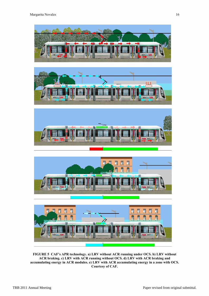
CAF’s ACR solution
CAF (Construcción y Auxiliar de Ferrocarriles) has been developing its ACR (Rapid Charge
Accumulator) OCS-free system in conjunction with Trainelec and Aragon Technical Institute [5].
The super-capacitors can be fully charged, while the train is stopped in a station, in around 20
seconds [5]. In addition, as for the rest of technologies, the system recovers the energy stored on the
journey and the braking energy too [10].
The roof-mounted accumulator is suitable for rolling stock of any manufacturer, as well as any
new or existing installations or infrastructure [10]. It can be complemented with NiMH batteries as back-
up for solving super-capacitor’s failure situations.
The implementation of ACR in a light rail vehicle increases its weight around 2 t per module.
With the common solution for OCR-free systems of two modules, this leads to an increase of 4 t. The
increase of weight is compensated with the energy saving.
The system has been tested during one year, in a first stage in Vélez-Málaga, and in May 2010,
the first tram provided with ACR initiated its commercial service in Seville (Spain). These vehicles will
allow the OCS to be definitely eliminated in the whole Seville network but at stations [11].
CAF assures that these vehicles can achieve a maximum autonomy of 1000 m, but in the
commercial service 500 m are guaranteed with active auxiliary systems [11].
In relation to vehicle’s overcost due to super-capacitor provision, CAF assures that in the next
developments it can be around 10-15%. Super-capacitor’s life depends on temperatures and
charge/uncharge cycles. For Seville, this life is expected to be around 7-8 years.
An illustration of ACR’s performance is presented in Figure 5.
Siemen’s Sitras HES solution
The Siemen’s Sitras-HES solution consists of two energy storage devices: the Sitras-MES (super-
capacitor mobile energy storage unit) and a NiMH battery. This concept combines, as CAF’s ACR, the
benefits of the super-capacitors with the characteristics of a traction battery. The capacitors recharge
faster and deliver the energy faster than traction batteries, which release their stored energy over longer
periods.
The roof-mounted modules have been installed in spare roof space on a Siemens Combino Plus
vehicle, and are electrically connected to the vehicle's energy supply point. This means that Sitras can be
easily retrofitted to older vehicles, including those of other manufacturers [5].
Sitras-HES can complete its charging cycle in 20 seconds, taking power from the catenary or a
charging point while the vehicle is standing in a station. This provides sufficient power for the vehicle to
run independently for up to 2.5 km, depending on the operating conditions [5].
Siemens began work on this system in September 2007, and it has been used on Lisbon's Metro
South light rail network (Portugal) since November 2008. Indeed, the Sitras-HES is being successfully
TRB 2011 Annual Meeting Paper revised from original submittal.
Margarita Novales 8
used in everyday passenger transport operation. The test vehicle is operated without overhead power
supply on a 2.6% gradient with auxiliary power of 5 kW and a maximum speed of 30 km/h [5].
In Germany Sitras has also been approved for use in public passenger transportation, in
accordance with BOStrab (a legal ordinance governing the manufacture and operation of streetcars) [5].
2.3 Electric energy produced on-board the vehicle
There are different possibilities to generate electric energy on-board the trams. They are, basically, fuel
systems such as hydrogen fuel-cells, hydrogen internal combustion engines, and diesel-electric generator
sets.
The hydrogen-based systems have not been yet advanced to a point where they can be applied to
a transit vehicle for commercial application. Fuel-cell technology continues to be developed along with
the infrastructure required for hydrogen fuel-cells (storage tanks and pumping equipment for refueling the
vehicles), and while it seems to be a promising technology, it is not still mature enough. Finally, diesel-
electric generator sets have been used in various applications in the world, but the industry is moving
away from fossil fuel based systems [2].
Therefore, this third range of solutions does not seem to be a good option for avoiding the use of
OCS wires in a short-term future.
3 CONCLUSIONS
The only solution that can absolutely avoid the use of OCS wires in the whole network is the ETR.
Among the different available technologies, some of them have a high degree of development and testing,
and others are more in the testing stage. In general, they are capital cost intensive, it is supposed that they
will have higher operation and maintenance costs and they will require more substantial safety
certification [2]. In some of them, it is necessary to assure the prevention of stray current problems under
some environmental conditions.
On the other hand, an additional concern can be related to the proprietary nature of the
technology and the potential to become dependent on a single supplier.
In general, it must be highlighted that the implementation of the ETR technology in all or part of
the network will represent an increase in the construction costs, although the statement from section 2.1.1
relating to the entailed percentage of total costs can be applied to every one of the existing technologies.
In a near future, it is possible that manufacturers will be able to keep the promise made to be
nearly cost neutral, and may some day even prove more cost-effective, but this is not the case today.
On the contrary, the technology that is more developed and more cost-effective nowadays is the
use of batteries/super-capacitors or a combination of them for energy storage in the vehicle. The storage
devices capture and hold energy, both from regenerative braking, from OCS wires where they are
provided, and from charging stations, and use it where the OCS is not available. The size and weight of
the energy storage device will be related to the amount of energy to store, and so, to the layout of the
track and the vehicle’s weight.
For these solutions, attention must be drawn to charging times, independence range, and
maximum power allowed by the system.
These solutions have the additional advantage that they can be mounted in old vehicles and in
the ones supplied by manufacturers that do not have this kind of technology. So, they are not so penalized
by proprietary problems.
In general, it is important to note that the equipment that is not service proven can result in costly
failures, train service delays, traffic disruptions, retrofits, equipment damage, or even employee or
passenger injury. Nevertheless, proven-technologies are emerging that will be able to avoid overhead
wires at least in the more sensitive areas of cities. This new advance can be the fact that propels the
implementation of light rail networks in some reticent communities.
ACKNOWLEDGEMENTS
The author thanks the collaborations of cited manufacturers for their contribution with documentation
about their systems.
REFERENCES
1. Vuchic, V.R. Urban Transit Systems and Technology. John Wiley & Sons Inc., New York,
2007. ISBN: 978-0-471-75823-5.
TRB 2011 Annual Meeting Paper revised from original submittal.
Margarita Novales 9
2. URS Corporation. Streetcar Technology Assessment. City of Charlotte Engineering &
Property Management, Charlotte, North Calorina, May 2010.
3. Boorse, J.W. Directly and Indirectly Reducing Visual Impact of Electric Railway Overhead
Contact Systems. In Transportation Research Record: Journal of the Transportation Research
Board, No. 1930, Transportation Research Board of the National Academies, Washington,
D.C., 2005, pp. 57-61.
4. Boorse, J.W. Dual-Mode Traction Power Distribution for Light Rail Transit. A Design Option.
In Transportation Research Record: Journal of the Transportation Research Board, No. 1677,
Transportation Research Board of the National Academies, Washington, D.C., 1999, pp. 67-
72.
5. Barrow, K. Wireless connections. International Railway Journal, Simmons-Boardman
Publishing Corporation, Cornwall, United Kingdom, June 2009.
6. City of Otawa. Power collection and distribution systems. On-line available:
http://www.ottawa.ca/residents/public_consult/tmp/lrt/discussion_papers/power_collect_en.ht
ml. Access on july 2010.
7. IRJ. Kawasaki Heavy Industries, Japan, could offer considerable savings in energy and
infrastructure costs. International Railway Journal, Simmons-Boardman Publishing
Corporation, Cornwall, United Kingdom, August 2008.
8. Hope, R. UltraCaps win out in energy storage. Raiway Gazette International, DVV Media UK
Ltd., July 2006.
9. Barrow, K. Power to the people: the development of supercapacitors has spawned a flurry of
'energy tank' systems from LRV manufacturers. International Railway Journal, Simmons-
Boardman Publishing Corporation, Cornwall, United Kingdom, September 2009.
10. Thomas, G. The CAF Rapid Charge Accumulator: Technology for Removing Catenary
Between Stations, Tecnirail, Montané Comunicación S.L., Madrid, Spain, June 2009.
11. Rodríguez, A. Tranvía sin catenaria desarrollado por CAF y basado en el empleo de
ultracondensadores. Vía Libre, Fundación de los Ferrocarriles Españoles, Madrid, Spain,
February 2009.
TRB 2011 Annual Meeting Paper revised from original submittal.
Margarita Novales 10
TABLE INDEX
Table 1: “Comparison between on-board energy storage devices”. Source: Modified from [6].
FIGURE INDEX
Figure 1: “a) Overhead contact wires in Tenerife’s light rail network (Spain). b) Miami’s street with
electric wires close-up”.
Figure 2: “Alstom’s APS solution. a) General diagram. b) ETR detail”.
Figure 3: “Ansaldo’s TramWave system. a) ETR. b) Pick-up shoe. c) Diagram of pick-up process”.
Figure 4: “Bombardier’s PRIMOVE system. a) Technology base. b) Vehicle’s diagram”.
Figure 5: “CAF’s APR technology. a) LRV without ACR running under OCS. b) LRV without ACR
braking. c) LRV with ACR running without OCS. d) LRV with ACR braking and accumulating energy in
ACR modules. e) LRV with ACR accumulating energy in a zone with OCS”.
TRB 2011 Annual Meeting Paper revised from original submittal.
Margarita Novales 11
TABLE 1 Comparison between on-board energy storage devices. Source: Modified from [6]
STORAGE
SYSTEM
Rate of
charge
Life cycle
cost
Life
expectancy
Cost/Power
storage
Power
density/Weight Safety
Super-
capacitor
Very short
charge Medium High High 6 kWh/kg High
Flywheel Short
charge time Medium Unknown High ? (low)
Low – Not
proved
Battery Long
charge time Medium Limited life Low 30-160 kWh/kg High
TRB 2011 Annual Meeting Paper revised from original submittal.
Margarita Novales 12
FIGURE 1 a) Overhead contact wires in Tenerife’s light rail network (Spain). b) Miami’s street
with electric wires close-up.
TRB 2011 Annual Meeting Paper revised from original submittal.
Margarita Novales 13
FIGURE 2 Alstom’s APS solution. a) General diagram. b) ETR detail. Courtesy of Alstom.
TRB 2011 Annual Meeting Paper revised from original submittal.
Margarita Novales 14
FIGURE 3 Ansaldo’s TramWave system. a) ETR. b) Pick-up shoe. c) Diagram of pick-up process.
Courtesy of Ansaldo.
TRB 2011 Annual Meeting Paper revised from original submittal.
Margarita Novales 15
FIGURE 4 Bombardier’s PRIMOVE system. a) Technology base. b) Vehicle’s diagram. Courtesy
of Bombardier.
TRB 2011 Annual Meeting Paper revised from original submittal.
Margarita Novales 16
FIGURE 5 CAF’s APR technology. a) LRV without ACR running under OCS. b) LRV without
ACR braking. c) LRV with ACR running without OCS. d) LRV with ACR braking and
accumulating energy in ACR modules. e) LRV with ACR accumulating energy in a zone with OCS.
Courtesy of CAF.
TRB 2011 Annual Meeting Paper revised from original submittal.