Power rail overhead Line - Bentley · design rules and checks Promote conformance to Standards...
4
PRODUCT DATA SHEET Power Rail Overhead Line Fast and Accurate Design for Rail Overhead Line Systems Integrated Rules and Design Checks Identify Potential Problems Power Rail Overhead Line utilizes the track geometry of Power Rail Track – Bentley’s application for preliminary and detailed 3D design of rail infrastructure. Integrated rules and design checks identify potential problems, alerting users when standards are exceeded. Power Rail Overhead Line provides flexibility and control for real-life design scenarios, enabling teams to improve quality, reduce rework, and meet project deadlines. Power Rail Overhead Line supports a diverse range of rail networks – high speed, conventional, and metro – as well as a variety of rail-related equipment manufacturers. The software effectively accom- modates hybrid systems where old and new technologies merge and often share OLE structures. Power Rail Overhead Line allows users to create relational, dynamic 3D models within which interactive changes can be made while element relationships such as mast, wires, structures, and assemblies are maintained and reflected immediately. Power Rail Overhead Line enables users to generate realistic 3D models for analysis and visualization. Users can also produce fully-annotated project drawings and deliverables for client approval and construction, and XML/XSL reports and schedules for design check sheets, cost estimates, delivery schedules, construction pick lists, and setting out on site. Power Rail Overhead Line promotes consistency and conformance to project standards. Connectivity throughout the entire process ensures OLE engineers can apply their engineering skill and judgment to achieve optimal design. After commissioning, data defining the OLE asset is provided to maintenance and operations for sustaining the network lifecycle – improving service, safety and reliability. Integrated CAD, Mapping and GIS for Improved Decision Making Power Rail Overhead Line delivers all the drafting and draw- ing production capabilities of MicroStation ® within a single application. The strengths of Power Rail Overhead Line are enhanced by Civil AccuDraw, the civil-specific version of MicroStation AccuDraw ® – an intuitive, precision drafting tool that anticipates the user’s intent, reducing the number of mouse clicks and other actions required to achieve drafting tasks. Civil AccuDraw streamlines the drafting process by supporting civil-specific drafting conventions with options for station and offsets, bearings and distances, azimuths, and more. Today’s engineers and designers face a paradigm shift. No longer are documents just for the current project or construc- tion. An engineer must provide information and designs that can carry beyond construction into operations, maintenance, and rehabilitation – and back to design if necessary. Power Rail Overhead Line uniquely supports this evolution of civil engineering information, encompassing the entire civil project lifecycle. The information-rich modeling of Power Rail Overhead Line integrates with CAD, mapping, GIS, and even business tools like 3D PDFs, offering powerful capabilities that makes the most of the engineer’s acquired knowledge while supporting traditional, proven methodologies. Power Rail Overhead Line is a comprehensive application for the system layout, preliminary and detailed design, and detailing of overhead traction power supply systems. The software follows established industry workflows and offers a high degree of automation, delivering significant productivity improvements and time savings for the design and maintenance of overhead line electrification (OLE) on global rail infrastructure projects. Built-in user-configurable design rules to optimize mast spacing, stagger and wind deflection, together with built-in design checking. Power Rail Overhead Line contains a comprehensive set of mapping and GIS data compilation and editing tools. Power Rail Overhead Line offers a com- plete range of tools to work automati- cally with survey, GPS, LiDAR, and other forms of field data. Image courtesy of Nave Newell, USA. Versatile editing tools highlight potential conflicts between proposed OLE structures and surrounding infrastructure, assuring collision-free design, optimal positioning and quantities.
Transcript of Power rail overhead Line - Bentley · design rules and checks Promote conformance to Standards...

Product data Sheet
Power rail overhead LineFast and Accurate Design for Rail Overhead Line Systems
Integrated rules and design checks Identify Potential ProblemsPower Rail Overhead Line utilizes the track geometry of Power Rail Track – Bentley’s application for preliminary and detailed 3D design of rail infrastructure. Integrated rules and design checks identify potential problems, alerting users when standards are exceeded. Power Rail Overhead Line provides flexibility and control for real-life design scenarios, enabling teams to improve quality, reduce rework, and meet project deadlines. Power Rail Overhead Line supports a diverse range of rail networks – high speed, conventional, and metro – as well as a variety of rail-related equipment manufacturers. The software effectively accom-modates hybrid systems where old and new technologies merge and often share OLE structures. Power Rail Overhead Line allows users to create relational, dynamic 3D models within which interactive changes can be made while element relationships such as mast, wires, structures, and assemblies are maintained and reflected immediately.
Power Rail Overhead Line enables users to generate realistic 3D models for analysis and visualization. Users can also produce fully-annotated project drawings and deliverables for client approval and construction, and XML/XSL reports and schedules for design check sheets, cost estimates, delivery schedules, construction pick lists, and setting out on site. Power Rail Overhead Line promotes consistency and conformance to project standards. Connectivity throughout the entire process ensures OLE engineers can apply their engineering skill and judgment to achieve optimal design. After commissioning, data defining the OLE asset is provided to maintenance and operations for sustaining the network lifecycle – improving service, safety and reliability.
Integrated cad, Mapping and GIS for Improved decision MakingPower Rail Overhead Line delivers all the drafting and draw-ing production capabilities of MicroStation® within a single application. The strengths of Power Rail Overhead Line are
enhanced by Civil AccuDraw, the civil-specific version of MicroStation AccuDraw® – an intuitive, precision drafting tool that anticipates the user’s intent, reducing the number of mouse clicks and other actions required to achieve drafting tasks. Civil AccuDraw streamlines the drafting process by supporting civil-specific drafting conventions with options for station and offsets, bearings and distances, azimuths, and more.
Today’s engineers and designers face a paradigm shift. No longer are documents just for the current project or construc-tion. An engineer must provide information and designs that can carry beyond construction into operations, maintenance, and rehabilitation – and back to design if necessary. Power Rail Overhead Line uniquely supports this evolution of civil engineering information, encompassing the entire civil project lifecycle. The information-rich modeling of Power Rail Overhead Line integrates with CAD, mapping, GIS, and even business tools like 3D PDFs, offering powerful capabilities that makes the most of the engineer’s acquired knowledge while supporting traditional, proven methodologies.
Power Rail Overhead Line is a comprehensive application for the system layout, preliminary and detailed design, and detailing of overhead traction power supply systems. The software follows established industry workflows and offers a high degree of automation, delivering significant productivity improvements and time savings for the design and maintenance of overhead line electrification (OLE) on global rail infrastructure projects.
Built-in user-configurable design rules to optimize mast spacing, stagger and wind deflection, together with built-in design checking.
Power Rail Overhead Line contains a comprehensive set of mapping and GIS data compilation and editing tools.
Power Rail Overhead Line offers a com-plete range of tools to work automati-cally with survey, GPS, LiDAR, and other forms of field data.
Image courtesy of Nave Newell, USA.
Versatile editing tools highlight potential conflicts between proposed OLE structures and surrounding infrastructure, assuring collision-free design, optimal positioning and quantities.

design rules and checks Promote conformance to Standards Power Rail Overhead Line includes user-configurable design rules to optimize mast spacing, stagger and wind deflection, and design checks to monitor parameters that include registration arm axial
force, wire gradient and change of wire gradient. Supporting scheme and detailed design processes, the system works the way an OLE designer works. An intuitive, graphical user interface provides easy access to interactive design tools for the layout of OLE structures, enabling users to sketch alternative layouts while investigating design options.
From the first step, design rules check the evolving system layout and geometry against requisite parameters. Streamlining users’ efforts, the software lays out structures and wire paths, automatically build-ing a fully-coordinated 3D model for design validation and use in such downstream activities as visualization and virtual reality modeling.
View, analyze and adjust height, stagger and wire gradient via an interactive, graphic interface.
Industry-recognized Workflow to Increase Productivity
data Import and analysisPower Rail Overhead Line offers a full complement of functionality that enables users to work automatically with survey, GPS, LiDAR, and other forms of field data including track geometry data. The software supports the leading devices and formats, handling a broad array of existing topography information. Users can calculate adjust-ments using any of the industry-standard methods, before modifying and processing the data as needed.
The software includes the ability to import geometry from 3D track models created and manipulated in Bentley Rail Track and Power Rail Track, existing graphics, or via LandXML. This enables Power Rail Overhead Line to view, annotate and report on any related topography and rail geometry used as the foundation for OLE design. In addition, other Bentley civil products provide information-rich, dynamic 3D models that are ready for immediate use in horizontal, vertical and cant dimensions.
obstacle Zones
Utilizing track geometry, OLE engineers identify restrictions along the length of the project. These restrictions or “fixed zones” determine the placement of masts to avoid bridges and other obstacles – even underground utilities. Overlaps and neutral sections are defined as
“Parametric structures deliver significant time savings in the design process, driving consistency and quality.”
ConfigurationData AssemblyContent Management Integration
Project Preparation
Track Network Model – Creation/Update
Indentification of Constraints
Design Planning
OLE Model Creation
Design Checking/Dynamic Editing
Automate Scheme Layout
Indentification of Constraints
Wiring Design – Contacts/Catenary/Droppers
Plan Preparation• Layout• Profiles• Cross-sections
Reports/Schedules• Dropper Schedules• Wiring Schedules• Bill of Materials
Project Deliverables
Direct from 3D Design Model• Data Export• 2D/3D Adobe PDF Creation• Visualization
Project Deliverables
Overhead Line System – Design Process.
well. Users can also identify over-track obstructions, enabling the software to compute maximum and minimum clearances for tunnels, crossings and any modeled encumbrance.
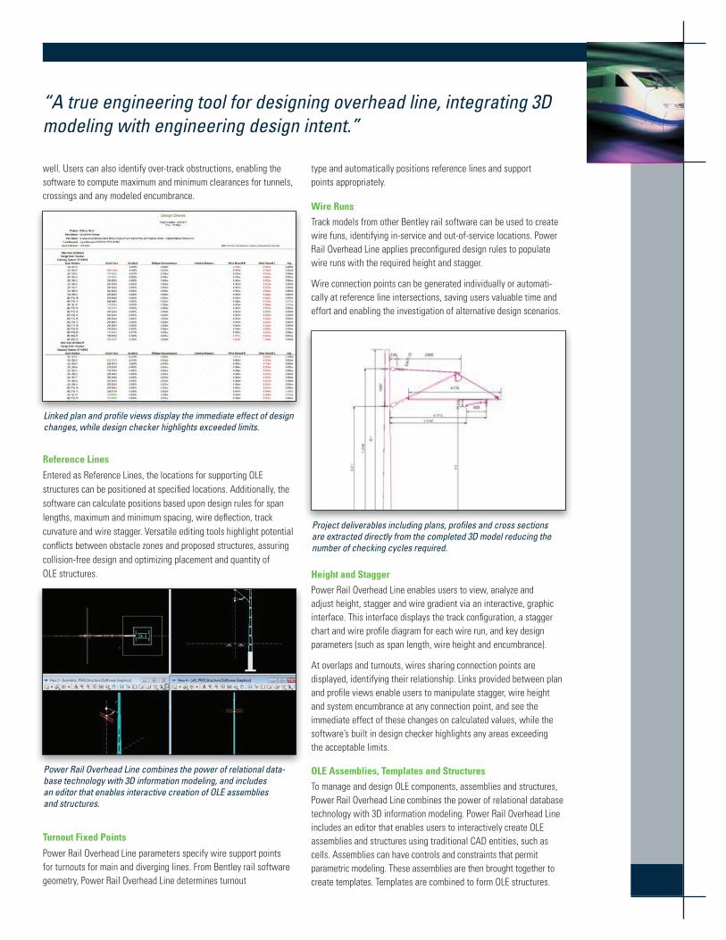
Linked plan and profile views display the immediate effect of design changes, while design checker highlights exceeded limits.
reference Lines
Entered as Reference Lines, the locations for supporting OLE structures can be positioned at specified locations. Additionally, the software can calculate positions based upon design rules for span lengths, maximum and minimum spacing, wire deflection, track curvature and wire stagger. Versatile editing tools highlight potential conflicts between obstacle zones and proposed structures, assuring collision-free design and optimizing placement and quantity of OLE structures.
Power Rail Overhead Line combines the power of relational data-base technology with 3D information modeling, and includes an editor that enables interactive creation of OLE assemblies and structures.
turnout Fixed Points
Power Rail Overhead Line parameters specify wire support points for turnouts for main and diverging lines. From Bentley rail software geometry, Power Rail Overhead Line determines turnout
type and automatically positions reference lines and support points appropriately.
Wire runs
Track models from other Bentley rail software can be used to create wire funs, identifying in-service and out-of-service locations. Power Rail Overhead Line applies preconfigured design rules to populate wire runs with the required height and stagger.
Wire connection points can be generated individually or automati-cally at reference line intersections, saving users valuable time and effort and enabling the investigation of alternative design scenarios.
Project deliverables including plans, profiles and cross sections are extracted directly from the completed 3D model reducing the number of checking cycles required.
height and Stagger
Power Rail Overhead Line enables users to view, analyze and adjust height, stagger and wire gradient via an interactive, graphic interface. This interface displays the track configuration, a stagger chart and wire profile diagram for each wire run, and key design parameters (such as span length, wire height and encumbrance).
At overlaps and turnouts, wires sharing connection points are displayed, identifying their relationship. Links provided between plan and profile views enable users to manipulate stagger, wire height and system encumbrance at any connection point, and see the immediate effect of these changes on calculated values, while the software’s built in design checker highlights any areas exceeding the acceptable limits.
oLe assemblies, templates and Structures
To manage and design OLE components, assemblies and structures, Power Rail Overhead Line combines the power of relational database technology with 3D information modeling. Power Rail Overhead Line includes an editor that enables users to interactively create OLE assemblies and structures using traditional CAD entities, such as cells. Assemblies can have controls and constraints that permit parametric modeling. These assemblies are then brought together to create templates. Templates are combined to form OLE structures.
“A true engineering tool for designing overhead line, integrating 3D modeling with engineering design intent.”
Components – additional items required for erection (such as nuts and bolts) – are assigned as attributes to assemblies and structures. Parametric assemblies and templates allow a single template to contain variations and dependencies supporting changes in track geometry and spacing, curvature, cant, wire height and wire stagger. When applied to a series of reference lines, templates create multiple structures in one process. Template automation and design checks:
• Identify where parameters have been exceeded;• Simplify the design process; • Deliver significant productivity improvements;• Drive consistency through the reduction of non-standard
OLE structures on a project; and • Improve overall quality of design in both heavy and light-
rail systems.
Power Rail Overhead Line provides a library of typical OLE configurations where assemblies, templates and structures can be stored for reuse or reconstitution into other templates and structures. This library can be saved as a corporate, project or individual standard.
© 2011 Bentley Systems, Incorporated. Bentley, the “B” Bentley logo, MicroStation, and AccuDraw are either registered or unregistered trademarks or service marks of Bentley Systems, Incorporated or one of its direct or indirect wholly owned subsidiaries. Other brands and product names are trademarks of their respective owners. BAA018990-1/0001 10/11
Find out about Bentley at www.bentley.comcontact Bentley1-800-BENTLEY (1-800-236-8539) Outside the US +1 610-458-5000
Global office Listingswww.bentley.com/contact
System requirementsProcessors:Intel Pentium-based or AMD Athlon-based PC or workstation
operating Systems:Microsoft Windows 7, Windows 7 x64, Windows Vista, Windows Vista x64, Windows XP Professional (SP3 or later)
Memory:1 GB minimum, 2 GB recommended, (more memory typically results in better performance)
disk Space:1.25 GB minimum free disk space
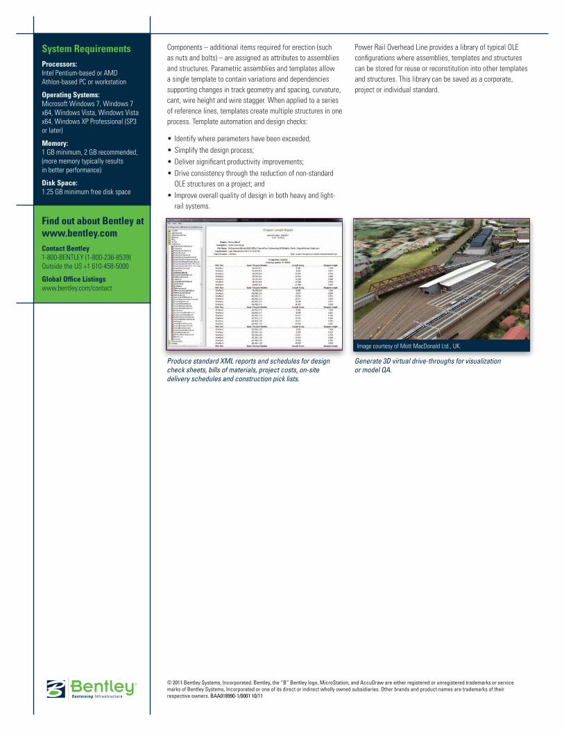
Produce standard XML reports and schedules for design check sheets, bills of materials, project costs, on-site delivery schedules and construction pick lists.
Generate 3D virtual drive-throughs for visualization or model QA.
Image courtesy of Mott MacDonald Ltd., UK.