Overhead Set Page 1 of 17 Overhead Set (003-004)€¦ · 03/11/2008 · Overhead Set (003-004)...
17
Overhead Set (003-004) Table of Contents Summary Summary General Information Preparatory Steps Adjust CELECT™ or CELECT™ Plus STC Finishing Steps Stepblock Disconnect batteries. Refer to Procedure 013-009 Stepblock Remove rocker lever covers. Refer to Procedure 003-011 Stepblock Remove engine brakes, if applicable. Refer to Procedure 020-001 Stepblock Adjust overhead. Engine must be cold. Max: 60°C [140°F]. Stepblock Tighten rocker lever shaft capscrews. Torque: 156 N•m [115 ft-lb]. Stepblock Tighten six rocker lever housing capscrews in proper sequence. See detail. Stepblock Tighten injector hold down capscrews. Torque: 41 N•m [30 ft-lb]. Stepblock Stepblock Stepblock Stepblock Stepblock Rotate accessory drive. Clockwise until “A” mark is aligned with gear cover mark. Firing order: 1-5- 3-6-2-4. Stepblock Verify valve rocker levers on cylinder number 1 closed. Stepblock If not closed, rotate accessory drive and align “A” with pointer. Stepblock Clean injector timing plunger on all injectors to be set. See detail. Page 1 of 17 Overhead Set 10/31/2008 https://quickserve.cummins.com/qs2/pubsys2/xml/en/procedures/09/09-003-004-tr.html
Transcript of Overhead Set Page 1 of 17 Overhead Set (003-004)€¦ · 03/11/2008 · Overhead Set (003-004)...

Overhead Set (003-004)
Table of Contents
Summary
Summary
General Information
Preparatory Steps
Adjust
CELECT™ or CELECT™ Plus
STC
Finishing Steps
Stepblock Disconnect batteries. Refer to Procedure 013-009
Stepblock Remove rocker lever covers. Refer to Procedure 003-011
Stepblock Remove engine brakes, if applicable. Refer to Procedure 020-001
Stepblock Adjust overhead. Engine must be cold. Max: 60°C [140°F].
Stepblock Tighten rocker lever shaft capscrews. Torque: 156 N•m [115 ft-lb].
Stepblock Tighten six rocker lever housing capscrews in proper sequence.
See detail.
Stepblock Tighten injector hold down capscrews. Torque: 41 N•m [30 ft-lb].
Stepblock Stepblock Stepblock Stepblock Stepblock Rotate accessory drive.
Clockwise until “A” mark is aligned with gear cover mark. Firing order: 1-5-3-6-2-4.
Stepblock Verify valve rocker levers on cylinder number 1 closed.
Stepblock If not closed, rotate accessory drive and align “A” with pointer.
Stepblock Clean injector timing plunger on all injectors to be set.
See detail.
Page 1 of 17Overhead Set
10/31/2008https://quickserve.cummins.com/qs2/pubsys2/xml/en/procedures/09/09-003-004-tr.html

Stepblock Loosen injector adjusting screw locknut.
Stepblock Tighten adjusting screw on injector rocker lever until timing plunger contacts bottom.
Stepblock Back out adjusting screw on rocker lever. 0.50 to 0.74 mm [0.020 to 0.029 in].
Stepblock Stepblock Hold adjusting screw and tighten lock nut.
Torque: 65 N•m [50 ft-lb].
Stepblock Stepblock Measure valve lash clearance.
Intake: 0.35 mm [0.014 in]. Exhaust: 0.68 mm [0.027 in]. Torque Wrench Method: 0.68 N•m [6 in-lb]. Feel Method: Tighten until slight drag.
Stepblock Hold adjusting screw in position and tighten.
Without wrench adapter: 68 N•m [50 ft-lb]. With wrench adapter: 54 N•m [40 ft-lb].
Stepblock Verify feeler gauge slides back and forth between crosshead and lever.
Slight drag felt.
Stepblock If feel method, insert feeler gauge between crosshead and rocker lever pad.
Feeler gauge: 0.03 mm [0.001 in].
Stepblock Rotate accessory drive. Firing order: 1-5-3-6-2-4.
Stepblock Adjust next valve set mark with pointer.
Stepblock Adjust proper injector and valves following chart.
See detail.
Stepblock Repeat process to adjust injectors and valves.
Stepblock Loosen lock nut on injector adjusting screw on cylinder number 5.
Stepblock Use dial type torque wrench and tighten injector rocker lever adjusting screw.
Torque: 14 N•m [125 in-lb].
Stepblock Tighten the lock nut. Torque: 65 N•m [50 ft-lb].
Stepblock Loosen locknuts on intake and exhaust valve adjusting screws.
Stepblock Select a feeler gauge for correct valve lash specification.
See detail.
Stepblock Choose method of adjusting. Torque Wrench Method.
Stepblock Choose method of adjusting. Feel Method.
Stepblock Check to make sure feeler gauge will slide backward and forward.
Stepblock(Feel Method) Install a thicker feeler gauge between crosshead and rocker lever pad.
Not correct if thicker feeler gauge fits.
Page 2 of 17Overhead Set
10/31/2008https://quickserve.cummins.com/qs2/pubsys2/xml/en/procedures/09/09-003-004-tr.html

Stepblock Rotate accessory drive for next adjustment.
Stepblock Injector and Valve adjusting chart See detail chart.
Stepblock Install rocker lever covers. Refer to Procedure 003-011.
Stepblock Install engine brakes, if applicable. Refer to Procedure 020-001.
Stepblock Connect the batteries. Refer to Procedure 013-009.
General Information TOC
WARNING Batteries can emit explosive gases. To reduce the possibility of personal injury, always ventilate the compartment before servicing the batteries. To reduce the possibility of arcing, remove the negative (-) battery cable first and attach the negative (-) battery cable last.
SMALL | MEDIUM | LARGE
Next
NOTE: Read the entire procedure for overhead adjustment before attempting to perform this operation.
Valves and injectors must be correctly adjusted for the engine to operate efficiently. Valve and injector adjustment must be performed using the values listed in this section.
Table 1, CELECT™ Plus Valve and Injector Adjustment Values
CELECT™ Plus Injector Adjustment: Bottom plunger, release, and bottom timing plunger. Back out two flats (120 degrees).
mm in
Intake Valve 0.35 0.014
Exhaust Valve 0.68 0.027
Engine brake 0.58 0.023
SMALL | MEDIUM | LARGE
Previous
Next
Page 3 of 17Overhead Set
10/31/2008https://quickserve.cummins.com/qs2/pubsys2/xml/en/procedures/09/09-003-004-tr.html

The preferred method of performing normal valve and step timing control (STC) injector overhead adjustment is to use the outer base circle (OBC) method, where the crush of the injector plunger to cup is set by tightening the injector rocker lever adjusting screw to a prescribed torque. If the STC injectors have been removed for cleaning and calibration, or if new ReCon injectors are being installed, use the OBC overhead set procedure.
Table 2, STC Valve and Injector Adjustment Values
STC Injector Adjustment (OBC Method): Torque to 14 N•m [125 in-lb].
mm in
Intake Valve 0.35 0.014
Exhaust Valve 0.68 0.027
Engine brake 0.58 0.023
SMALL | MEDIUM | LARGE
Previous
Next
Preparatory Steps TOC
� Disconnect the batteries. Refer to Procedure 013-009 � Remove the rocker lever covers. Refer to Procedure
003-011 � Remove the engine brakes, if applicable. Refer to
Procedure 020-001.
SMALL | MEDIUM | LARGE
Previous
Next
Summary 1
Summary 2
Summary 3
Adjust TOC
Page 4 of 17Overhead Set
10/31/2008https://quickserve.cummins.com/qs2/pubsys2/xml/en/procedures/09/09-003-004-tr.html

CELECT™ or CELECT™ Plus
All overhead (valve and injector) adjustments must be made when the engine is cold (any stabilized coolant temperature at 60°C [140°F] or below).
SMALL | MEDIUM | LARGE
Previous
Next
Summary 4
NOTE: After an engine rebuild or any major repair where the injector setting must be disturbed, set all the valves and injectors.
CELECT™ Plus injectors will provide acceptable engine performance with lash (OBC) anywhere from 0.51 to 2.04 mm [0.020 to 0.080 in]. The procedure for CELECT™ Plus injector reset will produce lash between 0.51 and 0.74 mm [0.020 and 0.029 in]. Under normal operation, there is never be a reason to adjust CELECT™ Plus injectors for excessive lash between scheduled maintenance intervals.
SMALL | MEDIUM | LARGE
Previous
Next
Tighten the rocker lever shaft capscrews.
Torque Value:
156 n.m
[115 ft-lb ]
SMALL | MEDIUM | LARGE
Previous
Next
Summary 5
Tighten the rocker lever housing capscrews in the sequence shown (1 through 6).
Page 5 of 17Overhead Set
10/31/2008https://quickserve.cummins.com/qs2/pubsys2/xml/en/procedures/09/09-003-004-tr.html

Tighten the rocker lever housing capscrews in the sequence shown (7 and 8).
1 Through 6 115 n.m [85 ft-lb ]
7 and 8 47 n.m [35 ft-lb ]
SMALL | MEDIUM | LARGE
Previous
Next
Summary 6
Tighten the injector hold down capscrews.
Torque Value:
41 n.m
[30 ft-lb ]
SMALL | MEDIUM | LARGE
Previous
Next
Summary 7
The valve set marks are located on the accessory drive pulley. The marks align with a pointer on the gear cover.
Use the accessory drive shaft to rotate the crankshaft.
WARNING Do not pull or pry on the fan to manually rotate the engine. To do so can damage the fan blades. Damaged fan blades can cause premature fan failures which can result in serious personal injury or property damage.
SMALL | MEDIUM | LARGE
Previous
Next
The crankshaft rotation is clockwise when viewed from the front of the engine.
The cylinders are numbered from the front end of the engine.
Page 6 of 17Overhead Set
10/31/2008https://quickserve.cummins.com/qs2/pubsys2/xml/en/procedures/09/09-003-004-tr.html

The engine firing order is 1-5-3-6-2-4.
SMALL | MEDIUM | LARGE
Previous
Next
Each cylinder has three rocker levers. The rocker lever nearest to the center of the housing is the intake lever.
Exhaust rocker lever (1)
Injector rocker lever (2)
Intake rocker lever (3)
The two levers closest to the center of each rocker housing are the intake rocker levers. The two levers closest to the ends of the rocker housing are the exhaust levers.
SMALL | MEDIUM | LARGE
Previous
Next
The valves and the injectors on the same cylinder are adjusted at the same index mark on the accessory drive pulley.
One pair of valves and one injector are adjusted at each pulley index mark before rotating the accessory drive to the next index mark.
Two crankshaft revolutions are required to adjust all of the valves and injectors.
Table 3, CELECT™ Plus Engines
Injector and Valve Adjustment Sequence
Bar Engine in Direction of Rotation
Pulley Position
Set Cylinder
Injector Valve
Start A 1 1
SMALL | MEDIUM | LARGE
Page 7 of 17Overhead Set
10/31/2008https://quickserve.cummins.com/qs2/pubsys2/xml/en/procedures/09/09-003-004-tr.html

Advance to B 5 5
Advance to C 3 3
Advance to A 6 6
Advance to B 2 2
Advance to C 4 4
Firing Order: 1-5-3-6-2-4
Previous
Next
Rotate the accessory drive in the direction of engine rotation. The accessory drive will rotate clockwise , on a right hand engine, when looking at the front of the engine. Align the "A" or "1-6 VS" mark on the accessory drive pulley with the pointer on the gear cover.
SMALL | MEDIUM | LARGE
Previous
Next
Summary 8
Check the valve rocker levers on cylinder number 1 to see if both valves are closed.
Both valves are closed when both rocker levers are loose and can be moved from side to side. If both valves are not closed, rotate the accessory drive one complete revolution; and align the "A" mark with the pointer again.
If the valve rocker lever adjusting screws have been loosened and not yet adjusted, watch the valve push tubes as the engine rolls upon the "A" mark. Both valve push tubes will have moved to the downward (valve closed) position if the engine is on the correct stroke.
SMALL | MEDIUM | LARGE
Previous
Next
Summary 9
Summary 10
WARNING When using solvents, acids, or alkaline materials for
Page 8 of 17Overhead Set
10/31/2008https://quickserve.cummins.com/qs2/pubsys2/xml/en/procedures/09/09-003-004-tr.html
Clean the timing plunger to remove the varnish from the top edge.
Apply a non-chlorinated carburetor cleaner (Pyroil or equivalent) using a narrow bore orifice or extension tube of 2 mm [0.79 in] maximum outside diameter, into the injector weep hole.
If the entire overhead is to be reset, every injector is to be sprayed at this time.
cleaning, follow the manufacturer's recommendations for use. Wear goggles and protective clothing to reduce the possibility of personal injury.
WARNING Some solvents are flammable and toxic. Read the manufacturer's instructions before using.
SMALL | MEDIUM | LARGE
Previous
Next
Summary 11
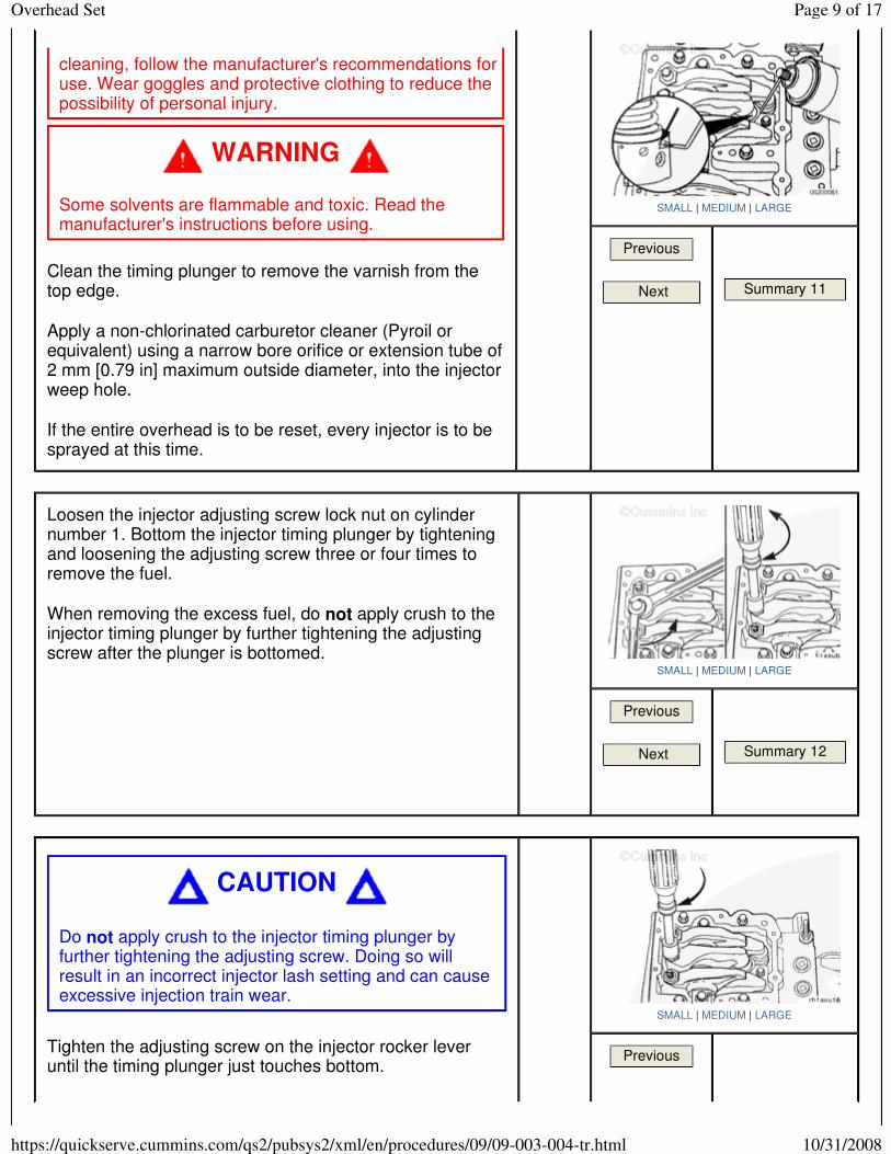
Loosen the injector adjusting screw lock nut on cylinder number 1. Bottom the injector timing plunger by tightening and loosening the adjusting screw three or four times to remove the fuel.
When removing the excess fuel, do not apply crush to the injector timing plunger by further tightening the adjusting screw after the plunger is bottomed.
SMALL | MEDIUM | LARGE
Previous
Next
Summary 12
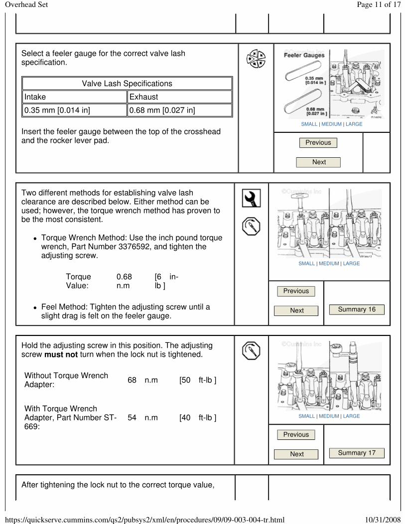
Tighten the adjusting screw on the injector rocker lever until the timing plunger just touches bottom.
CAUTION
Do not apply crush to the injector timing plunger by further tightening the adjusting screw. Doing so will result in an incorrect injector lash setting and can cause excessive injection train wear.
SMALL | MEDIUM | LARGE
Previous
Page 9 of 17Overhead Set
10/31/2008https://quickserve.cummins.com/qs2/pubsys2/xml/en/procedures/09/09-003-004-tr.html

Next
Summary 13
Back out the adjusting screw on the injector rocker lever two flats (120 degrees).
Two flats will provide 0.56 mm [0.022 in] lash. The specification is 0.50 to 0.74 mm [0.020 to 0.029 in] lash.
CAUTION
After bottoming the CELECT™ Plus injector timing plunger, make certain to back out the adjusting screw two flats (120 degrees) or damage to the injector will result.
SMALL | MEDIUM | LARGE
Previous
Next
Summary 14
Hold the adjusting screw and tighten the lock nut.
Torque Value:
65 n.m
[50 ft-lb ]
SMALL | MEDIUM | LARGE
Previous
Next
After setting the injector on a given cylinder, set the valves on the same cylinder.
With the "A" set mark aligned with the pointer on the gear cover and both valves closed on cylinder number 1, loosen the lock nuts on the intake and the exhaust valve adjusting screws.
SMALL | MEDIUM | LARGE
Previous
Next
Summary 15
Page 10 of 17Overhead Set
10/31/2008https://quickserve.cummins.com/qs2/pubsys2/xml/en/procedures/09/09-003-004-tr.html
Select a feeler gauge for the correct valve lash specification.
Insert the feeler gauge between the top of the crosshead and the rocker lever pad.
Valve Lash Specifications
Intake Exhaust
0.35 mm [0.014 in] 0.68 mm [0.027 in]
SMALL | MEDIUM | LARGE
Previous
Next
Two different methods for establishing valve lash clearance are described below. Either method can be used; however, the torque wrench method has proven to be the most consistent.
� Torque Wrench Method: Use the inch pound torque wrench, Part Number 3376592, and tighten the adjusting screw.
� Feel Method: Tighten the adjusting screw until a slight drag is felt on the feeler gauge.
Torque Value:
0.68 n.m
[6 in-lb ]
SMALL | MEDIUM | LARGE
Previous
Next
Summary 16
Hold the adjusting screw in this position. The adjusting screw must not turn when the lock nut is tightened.
Without Torque Wrench Adapter:
68 n.m [50 ft-lb ]
With Torque Wrench Adapter, Part Number ST-669:
54 n.m [40 ft-lb ]
SMALL | MEDIUM | LARGE
Previous
Next
Summary 17
After tightening the lock nut to the correct torque value,
Page 11 of 17Overhead Set
10/31/2008https://quickserve.cummins.com/qs2/pubsys2/xml/en/procedures/09/09-003-004-tr.html

check to make sure the feeler gauge will slide backward and forward between the crosshead and the rocker lever with only a slight drag.
SMALL | MEDIUM | LARGE
Previous
Next
Summary 18
Summary 20
If using the feel method, attempt to insert a feeler gauge that is 0.03 mm [0.001 in] thicker between the crosshead and the rocker lever pad. The valve lash is not correct when a thicker feeler gauge will fit.
SMALL | MEDIUM | LARGE
Previous
Next
Summary 19
After adjusting the injector on cylinder number 1 and the valves on cylinder number 1, rotate the accessory drive; and align the next valve set mark with the pointer.
SMALL | MEDIUM | LARGE
Previous
Next
Summary 21
Adjust the appropriate injector and valves following the Injector and Valve Adjustment Sequence in Table 4.
Repeat the process to adjust all injectors and valves
Page 12 of 17Overhead Set
10/31/2008https://quickserve.cummins.com/qs2/pubsys2/xml/en/procedures/09/09-003-004-tr.html

STC
correctly.
Table 4, CELECT™ Plus Engines
Injector and Valve Adjustment Sequence
Bar Engine in Direction of Rotation
Pulley Position
Set Cylinder
Injector Valve
Start A 1 1
Advance to B 5 5
Advance to C 3 3
Advance to A 6 6
Advance to B 2 2
Advance to C 4 4
Firing Order: 1-5-3-6-2-4
SMALL | MEDIUM | LARGE
Previous
Next
Summary 22
Summary 23
Loosen the lock nut on the injector adjusting screw on the cylinder number 5.
SMALL | MEDIUM | LARGE
Previous
Next
Summary 24
Use a dial type torque wrench to tighten the injector rocker lever adjusting screw to the specified torque. If the screw
CAUTION
An overtightened setting on the injector adjusting screw will produce increased stress on the injector train and the camshaft injector lobes, which can result in engine damage.
SMALL | MEDIUM | LARGE
Page 13 of 17Overhead Set
10/31/2008https://quickserve.cummins.com/qs2/pubsys2/xml/en/procedures/09/09-003-004-tr.html

causes chattering during setting, repair the screw and lever as required.
Hold the torque wrench in a position that allows the direct view of the dial. This is to make certain that the reading on the dial is accurate.
Torque Value:
14 n.m
[125 in-lb ]
Previous
Next
Summary 25
Hold the adjusting screw in this position. The adjusting screw must not turn when the lock nut is tightened. Tighten the lock nut.
Torque Value:
65 n.m
[50 ft-lb ]
SMALL | MEDIUM | LARGE
Previous
Next
Summary 26
With the “B” mark aligned with the pointer on the gear cover and both valves closed on cylinder number 5, loosen the locknuts on the intake and the exhaust valve adjusting screws.
SMALL | MEDIUM | LARGE
Previous
Next
Summary 27
Select a feeler gauge for the correct valve lash specification.
Valve Lash Specifications
mm in
Intake 0.35 NOM [0.014]
Exhaust 0.68 NOM [0.027]
SMALL | MEDIUM | LARGE
Page 14 of 17Overhead Set
10/31/2008https://quickserve.cummins.com/qs2/pubsys2/xml/en/procedures/09/09-003-004-tr.html

Insert the feeler gauge between the top of the crosshead and the rocker lever nose.
Previous
Next
Summary 28
Two different methods for establishing valve lash clearance are described below. Either method can be used: however, the torque wrench method has proven to be the most consistent.
Torque Wrench Method
� Use the inch-pound torque wrench, Part Number 3376592, or equivalent, (normally used to set preload on STC injectors), and tighten the adjusting screw.
Torque Value:
0.56 to 0.68 n.m
[5 to 6 in-lb ]
SMALL | MEDIUM | LARGE
Previous
Next
Summary 29
Feel Method
� Hold the adjusting screw in this position. The adjusting screw must not turn when the locknut is tightened. Tighten the locknut.
With torque wrench adapter, Part Number 3163196, or equivalent:
Without torque wrench adapter:
Torque Value:
55 n.m
[40 ft-lb ]
Torque Value:
65 n.m
[50 ft-lb ]
SMALL | MEDIUM | LARGE
Previous
Next
Summary 30
After tightening the locknut to the correct torque value, check to make sure the feeler gauge will slide backward and forward between the crosshead and the rocker lever with only a slight drag.
SMALL | MEDIUM | LARGE
Page 15 of 17Overhead Set
10/31/2008https://quickserve.cummins.com/qs2/pubsys2/xml/en/procedures/09/09-003-004-tr.html

Previous
Next
Summary 31
If using the feel method, attempt to insert a feeler gauge that is 0.03 mm [0.001 in] thicker between the crosshead and the rocker lever pad. The valve lash is not correct when a thicker feeler gauge will fit.
SMALL | MEDIUM | LARGE
Previous
Next
Summary 32
After adjusting the injector on cylinder number 5 and the valves on cylinder number 5, rotate the accessory drive.
Align the next valve set mark with the pointer.
SMALL | MEDIUM | LARGE
Previous
Next
Summary 33
Adjust the appropriate injector and valves following the Injector and Valve Adjustment Sequence in Table 5.
Repeat the process to adjust all injectors and valves correctly.
Table 5, STC Engine Outer Base Circle (OBC)
Injector and Valve Adjustment Sequence
Bar Engine in Direction of Rotation
Pulley Position
Set Cylinder
Injector Valve
SMALL | MEDIUM | LARGE
Page 16 of 17Overhead Set
10/31/2008https://quickserve.cummins.com/qs2/pubsys2/xml/en/procedures/09/09-003-004-tr.html

Last Modified: 06-Feb-2006
Feedback / Help
Copyright © 2006 Cummins Inc. All rights reserved
Start B 5 5
Advance to C 3 3
Advance to A 6 6
Advance to B 2 2
Advance to C 4 4
Advance to A 1 1
Firing Order: 1-5-3-6-2-4
Previous
Next
Summary 34
Finishing Steps TOC
� Install the rocker lever covers. Refer to Procedure 003-011
� Install the engine brakes, if applicable. Refer to Procedure 020-001
� Connect the batteries. Refer to Procedure 013-009
SMALL | MEDIUM | LARGE
Previous
Summary 35
Summary 36
Summary 37
Page 17 of 17Overhead Set
10/31/2008https://quickserve.cummins.com/qs2/pubsys2/xml/en/procedures/09/09-003-004-tr.html