OVER THE RANGE MICROWAVE OVEN SERVICE MANUAL
44
! ATTENTION ! This service manual is intended for use by persons having electrical and mechanical training and a level of knowledge of these subjects generally considered acceptable in the appliance repair trade. Electrolux Home Products cannot be responsible, nor assume any liability, for injury or damage of any kind arising from the use of this manual. OVER THE RANGE MICROWAVE OVEN SERVICE MANUAL Models FMV157GS FMV157GB FMV157GM FMV157GQ FMV157GC CFMV157GS CFMV157GB CFMV157GM CFMV157GQ CFMV157GC Part # 316439269 Publication # 5995528261 November 2008
Transcript of OVER THE RANGE MICROWAVE OVEN SERVICE MANUAL
! ATTENTION !This service manual is intended for use by persons having electrical and mechanical training and a level of knowledge of these subjects generally considered acceptable in the appliance repair trade. Electrolux Home Products cannot be responsible, nor assume any liability, for injury or damage of any kind arising from the use of this manual.
OVER THE RANGE MICROWAVE OVENSERVICE MANUAL
Models FMV157GSFMV157GBFMV157GMFMV157GQFMV157GC
CFMV157GSCFMV157GBCFMV157GMCFMV157GQCFMV157GC
Part # 316439269Publication # 5995528261 November 2008

Page 2
CONTENTS
TABLE OF CONTENTSPage
PRECAUTIONS TO BE OBSERVED BEFORE AND DURING SERVICING TOAVOID POSSIBLE EXPOSURE TO EXCESSIVE MICROWAVE ENERGY................................................................. 3BEFORE SERVICING.................................................................................................................................................. 3WARNING TO SERVICE PERSONNEL....................................................................................................................... 4MICROWAVE MEASUREMENT PROCEDURE........................................................................................................... 5FOREWORD AND WARNING ..................................................................................................................................... 6 PRODUCT SPECIFICATIONS ..................................................................................................................................... 7GENERAL INFORMATION........................................................................................................................................... 7OPERATION............................................................................................................................................................... 10TROUBLESHOOTING GUIDE .................................................................................................................................. 14TEST PROCEDURE .................................................................................................................................................. 16TOUCH CONTROL PANEL ASSEMBLY..................................................................................................................... 26COMPONENT REPLACEMENT AND ADJUSTMENT PROCEDURE....................................................................... 30SCHEMATIC DIAGRAM............................................................................................................................................. 38WIRING DIAGRAM .................................................................................................................................................... 39EXPLODED PARTS DIAGRAM.................................................................................................................................. 40PACKING AND ACCESSORIES ................................................................................................................................ 44

Page 32
PRECAUTIONS TO BE OBSERVED BEFORE AND DURING SERVICING TO AVOID POSSIBLE EXPO-SURE TO EXCESSIVE MICROWAVE ENERGY(a) Do not operate or allow the oven to be operated with the door open.(b) Make the following safety checks on all ovens to be serviced before activating the magnetron or other
microwave source, and make repairs as necessary: (1) interlock operation, (2) proper door closing, (3) seal and sealing surfaces (arcing, wear, and other damage), (4) damage to or loosening of hinges and latches, (5) evidence of dropping or abuse.
(c) Before turning on microwave power for any service test or inspection within the microwave generating compartments, check the magnetron, wave guide or transmission line, and cavity for proper alignment, integrity, and connections.
(d) Any defective or misadjusted components in the interlock, monitor, door seal, and microwave genera-tion and transmission systems shall be repaired, replaced, or adjusted by procedures described in this manual before the oven is released to the owner.
(e) A microwave leakage check to verify compliance with the Federal Performance Standard should be performed on each oven prior to release to the owner.
(RD8100U)
BEFORE SERVICINGBefore servicing an operative unit, perform a microwave emission check as per the Microwave Measurement Procedure outlined in this service manual.If microwave emissions level is in excess of the specified limit, contact ELECTROLUX HOME PRODUCTS, INC. immediately.
If the unit operates with the door open, service person should 1) tell the user not to operate the oven and 2) contact ELECTROLUX HOME PRODUCTS, INC. and Food and Drug Administration's Center for Devices and Radiological Health immediately.
Service personnel should inform ELECTROLUX HOME PRODUCTS, INC. of any certified unit found with emissions in excess of 4mW/cm2. The owner of the unit should be instructed not to use the unit until the oven has been brought into compliance.
FMV157GSFMV157GBFMV157GMFMV157GQFMV157GC
Page 4
3
WARNING TO SERVICE PERSONNELMicrowave ovens contain circuitry capable of pro-ducing very high voltage and current, contact with following parts may result in a severe, possibly fatal, electrical shock.(Example)High Voltage Capacitor, High Voltage Power Transformer, Magnetron, High Voltage Rectifier Assembly, High Voltage Harness etc..Read the Service Manual carefully and follow all instructions.
Before Servicing
1. Disconnect the power supply cord , and then remove outer case.
2. Open the door and block it open.3. Discharge high voltage capacitor.
WARNING:RISK OF ELECTRIC SHOCK. DISCHARGE THE HIGH-VOLTAGE CAPACITOR BEFORE SERVICING.
The high-voltage capacitor remains charged about 60 seconds after the oven has been switched off. Wait for 60 seconds and then short-circuit the connection of the high-voltage capacitor (that is the connecting lead of the high-voltage rectifier) against the chassis with the use of an insulated screwdriver.
Whenever troubleshooting is performed the power supply must be disconnected. It may, in some cases, be necessary to connect the power supply after the outer case has been removed, in this event,1. Disconnect the power supply cord, and then remove
outer case.2. Open the door and block it open.3. Discharge high voltage capacitor.4. Disconnect the leads to the primary of the power
transformer.5. Ensure that these leads remain isolated from other
components and oven chassis by using insulation tape.
6. After that procedure, reconnect the power supply cord.
When the testing is completed,1. Disconnect the power supply cord, and then remove
outer case.2. Open the door and block it open.3. Discharge high voltage capacitor.4. Reconnect the leads to the primary of the power
transformer.5. Reinstall the outer case (cabinet).6. Reconnect the power supply cord after the outer case
is installed.7. Run the oven and check all functions.
After repairing1. Reconnect all leads removed from components during
testing.2. Reinstall the outer case (cabinet).3. Reconnect the power supply cord after the outer case
is installed.4. Run the oven and check all functions.
Microwave ovens should not be run empty. To test for the presence of microwave energy within a cavity, place a cup of cold water on the oven turntable, close the door and set the power to HIGH and set the microwave timer for two (2) minutes. When the two minutes has elapsed (timer at zero) carefully check that the water is now hot. If the water remains cold carry out Before Servicing procedure and re-examine the connections to the component being tested.
When all service work is completed and the oven is fully assembled, the microwave power output should be checked and microwave leakage test should be carried out.
Don't Touch !Danger High Voltage
FMV157GSFMV157GBFMV157GMFMV157GQFMV157GC

Page 54
MICROWAVE MEASUREMENT PROCEDURE
A. Requirements:
1) Microwave leakage limit (Power density limit): The power density of microwave radiation emitted by a microwave oven should not exceed 1mW/cm2 at any point 5cm or more from the external surface of the oven, measured prior to acquisition by a purchaser, and thereafter (through the useful life of the oven), 5 mW/cm2 at any point 5cm or more from the external surface of the oven.
2) Safety interlock switches: Primary interlock switch shall prevent microwave radiation emission in excess of the requirement as above mentioned, secondary interlock relay and door sensing switch shall prevent microwave radiation emission in excess of 5 mW/cm2 at any point 5cm or more from the external surface of the oven.
B. Preparation for testing:Before beginning the actual measurement of leakage, proceed as follows:1) Make sure that the actual instrument is operating normally as specified in its instruction booklet.
Important:Survey instruments that comply with the requirement for instrumentation as prescribed by the performance standard for microwave ovens, 21 CFR 1030.10(c)(3)(i), must be used for testing.
2) Place the oven tray in the oven cavity.3) Place the load of 275±15 ml (9.8 oz) of tap water initially at 20±5½C (68½F) in the center of the oven cavity.
The water container shall be a low form of 600 ml (20 oz) beaker with an inside diameter of approx. 8.5 cm (3-1/2 in.) and made of an electrically nonconductive material such as glass or plastic.The placing of this standard load in the oven is important not only to protect the oven, but also to insure that any leakage is measured accurately.
4) Set the cooking control on Full Power Cooking Mode 5) Close the door and select a cook cycle of several minutes. If the water begins to boil before the survey is completed,
replace it with 275 ml of cool water.
C. Leakage test:
Closed-door leakage test (microwave measurement)1) Grasp the probe of the survey instrument and hold it perpendicular to the gap between the door and the body of the
oven.2) Move the probe slowly, not faster than 1 in./sec. (2.5 cm/sec.) along the gap, watching for the maximum indication on
the meter.3) Check for leakage at the door screen, sheet metal seams and other accessible positions where the continuity of the
metal has been breached (eg., around the switches, indicator, and vents).While testing for leakage around the door pull the door away from the front of the oven as far as is permitted by the closed latch assembly.
4) Measure carefully at the point of highest leakage and make sure that the highest leakage is no greater than 4mW/cm2,and that the primary interlock switch does turn the oven OFF before any door movement.
FMV157GSFMV157GBFMV157GMFMV157GQFMV157GC

Page 65
PRODUCT DESCRIPTION
GENERAL INFORMATION
OPERATION
TROUBLESHOOTING GUIDE AND TEST PROCEDURE
TOUCH CONTROL PANEL
COMPONENT REPLACEMENT AND ADJUSTMENT PROCEDURE
WIRING DIAGRAM
PARTS LIST
ELECTROLUX HOME PRODUCTS, INC.
SERVICE MANUAL
ELECTROLUX
OVER THE RANGEMICROWAVE OVEN
FMV156DBE / FMV156DSEFMV156DQE / FMV156DCF
FOREWORD
This Manual has been prepared to provide Electrolux Home Prod-uctsService Personnel with Operation and Service Information for the ELECTROLUX OVER THE RANGE MICROWAVE OVENS, FM-V156DBE, FMV156DSE, FMV156DQE, FMV156DCF.
It is recommended that service personnel carefully study the entire text of this manual so that they will be qualified to render satisfactory customer service.
Check the interlock switches and the door seal carefully. Special attention should be given to avoid electrical shock and microwave radiation hazard.
WARNINGNever operate the oven until the following points are ensured.(A) The door is tightly closed.(B) The door brackets and hinges are not defective.(C) The door packing is not damaged.(D) The door is not deformed or warped.(E) There is not any other visible damage with the oven.
Servicing and repair work must be carried out only by trained service personnel.
DANGERCertain initial parts are intentionally not grounded and present a risk of electrical shock only during servicing. Service personnel - Do not contact the following parts while the ap-pliance is energized; High Voltage Capacitor, Power Transformer, Magnetron, High Voltage Rectifier Assembly, High Voltage Harness; If provided, Vent Hood, Fan assembly, Cooling Fan Motor.
All the parts marked “ * ” on parts list are used at voltages more than 250V.
Removal of the outer wrap gives access to voltage above 250V.
All the parts marked “ ∆ ” on parts list may cause undue mi-crowave exposure, by themselves, or when they are damaged,
FMV157GSFMV157GBFMV157GMFMV157GQFMV157GC

Page 7
6
ITEM DESCRIPTIONPower Requirements 20 Volts / 15 Amperes
60 HertzSingle phase, 3 wire grounded
Power Output 1000 watts (IEC TEST PROCEDURE)Operating frequency of 2450MHz
Case Dimensions Width 29-7/8"Height 16-13/32Depth 15-1/32"
Cooking Cavity Dimensions Width 20-/4"Height 9-/4"
Depth 14-13/32"
Hood lamp 2 bulbs, 30W x 2, Incandescent light bulbs
Hood fan Approx. 300 C.F. (High mode)
Control Complement Touch Control SystemClock ( :00 - 2:59 )Timer (0 - 99 min. 99 seconds)
Microwave Power for Variable Cooking
Repetition Rate;P-HI .................................................. Full power throughout the cooking timeP-90..................................................................... approx. 90% of Full PowerP-80..................................................................... approx. 80% of Full PowerP-70..................................................................... approx. 70% of Full PowerP-60..................................................................... approx. 60% of Full PowerP-50..................................................................... approx. 50% of Full PowerP-40..................................................................... approx. 40% of Full PowerP-30 .................................................................... approx. 30% of Full PowerP-20..................................................................... approx. 20% of Full PowerP-0..................................................................... approx. 0% of Full PowerP-0..................................................... No power throughout the cooking time
Popcorn pad, Reheat pad, Cook pad, Defrost pad, Number selection pads Power Level pad, Timer / Clock pad Light button, Fan button,Clear/Off button, START/ Plus Min button,
Oven Cavity Light 30W x Incandescent light bulb
Safety Standard UL Listed FCC Authorized
DHHS Rules, CFR, Title 2, Chapter , Subchapter J
Weight Approx. 63.9lbs.
PRODUCT SPECIFICATION
GENERAL INFORMATION
GROUNDING INSTRUCTIONS
This oven is equipped with a three prong grounding plug. It must be plugged into a wall receptacle that is properly installed and grounded in accordance with the National Electrical Code and local codes and ordinances.In the event of an electrical short circuit, grounding reduces the risk of electric shock by providing an escape wire for the electric current.WARNING: Improper use of the grounding plug can result in a risk of electric shock.
FMV157GSFMV157GBFMV157GMFMV157GQFMV157GC
.5 Cubic Feet

Page 8
7
OVEN DIAGRAM
3-Pronged Plug
GroundedReceptacle Box
Grounding Pin
3-Pronged Receptacle
10
11
12
8
7
14
6
9
3
4
5
1
9
13
2
Electrical RequirementsThe oven is equipped with a 3-prong grounding plug. DO NOT UNDER ANY CIRCUMSTANCES CUT OR REMOVE THE GROUNDING PIN FROM THE PLUG.The power supply cord and plug must be connected to a separate 120 Volt AC, 60 Hz, 15 Amp. or more dedicated line, using a grounded receptacle. The receptacle should be located inside the cabinet directly above the Microwave Oven/Hood system mounting location.
1. Oven door with see-through window.2. Door hinges.3. Waveguide cover.4. Turntable motor shaft.5. Oven lamp.
It will light when oven is operating or door is open.
6. Door latches.The oven will not operate unless the door is securely closed.
7. Auto Touch control panel8. Time display: Digital display, 99 minutes 99
seconds.9. Ventilation openings.
10.Light Cover.11.Grease filters.12.Removable turntable.
The turntable will rotate clockwise or counterclockwise.Only remove for cleaning.
13.Removable turntable support.14. Power supply cord
FMV157GSFMV157GBFMV157GMFMV157GQFMV157GC
Page 9
8
CONTROL PANEL
FMV157GSFMV157GBFMV157GMFMV157GQFMV157GC

Page 109
OPERATION
DESCRIPTION OF OPERATING SEQUENCE
The following is a description of component functions dur-ing oven operation.
OFF CONDITIONClosing the door activates the door sensing switch and secondary interlock switch. (In this condition, the monitor switch contacts are opened.)When oven is plugged in, 120 volts A.C. is supplied to the control unit. (Figure O-1).
1. The display will show "WELCOME, PRESS CLEAR AND PRESS CLOCK".To set any program or set the clock, you must first touch the STOP/CLEAR pad. The display will clear, and " : " will appear .
COOKING CONDITIONProgram desired cooking time touching the NUMBER pads. When the START pad is touched, the following operations occur:
1. The contacts of relays are closed and components connected to the relays are turned on as follows.(For details, refer to Figure O-2)
RELAY CONNECTED COMPONENTS
RY1 Oven lamp / Fan motor
RY2 Power transformer
RY3 Cooktop lampRY4/5 Hood fan motor
2. 120 volts A.C. is supplied to the primary winding of the power transformer and is converted to about 3.3 volts A.C. output on the filament winding, and approximately 2200 volts A.C. on the high voltage winding.
3. The filament winding voltage heats the magnetron filament and the H.V. winding voltage is sent to a voltage doubler circuit.
4. The microwave energy produced by the magnetron is channelled through the waveguide into the cavity feed-box, and then into the cavity where the food is placed to be cooked.
5. Upon completion of the cooking time, the power transformer, oven lamp, etc. are turned off, and the generation of microwave energy is stopped. The oven will revert to the OFF condition.
6. When the door is opened during a cook cycle, monitor switch, door sensing switch, primary interlock switch, and secondary interlock relay are activated with the following results. The circuits to the stirrer motor, the cooling fan motor, the turntable motor, and the high voltage components are de-energized, and the digital read-out displays the time still remaining in the cook cycle when the door was opened.
7. The monitor switch is electrically monitoring the
of the primary interlock switch, and door sensing switch is mechanically associated with the door so that it will function in the following sequence.(1) When the door opens from a closed position, the
secondary interlock relay, door sensing switch, and primary interlock switch open their contacts, and then the monitor switch contacts close.
(2) When the door is closed from the open position, the monitor switch contacts open first. Then the contacts of the primary interlock switch and door sensing switch close. And contacts of the relay (RY1) open.
If the primary interlock switch and secondary interlock relay (RY2) fail with the contacts closed when the door is opened, the closing of the monitor switch contacts will form a short circuit through the monitor fuse, primary interlock switch, relay (RY1) and secondary interlock relay (RY2), causing the monitor fuse to blow.
POWER LEVEL P-0 TO P-90 COOKINGWhen Variable Cooking Power is programmed, the 120volts A.C. is supplied to the power transformer intermittently through the contacts of relay (RY2) which is operated by the control unit within an interval second time base. Microwave power operation is as follows:
VARI-MODE ON TIME OFF TIME
Power 10(P-HI) 29 sec. 0 sec.(100% power)
Power 9(P-90) 26 sec. 3 sec.(approx. 90% power)
Power 8(P-80) 23 sec. 6 sec.(approx. 80% power)Power 7(P-70) 20 sec. 9 sec.(approx. 70% power)
Power 6(P-60) 17 sec. 12 sec.(approx. 60% power)
Power 5(P-50) 14 sec. 15 sec.(approx. 50% power)
Power 4(P-40) 11 sec. 18 sec.(approx. 40% power)
Power 3(P-30) 8 sec. 21 sec.(approx. 30% power)
Power 2(P-20) 5 sec. 24 sec.(approx. 20% power)
Power 1(P-10) 3 sec. 26 sec.(approx. 10% power)
Note: The ON/OFF time ratio does not correspond with the percentage of microwave power, because approx. 2 seconds are needed for heating of the magnetron
FMV157GSFMV157GBFMV157GMFMV157GQFMV157GC
Page 11 10
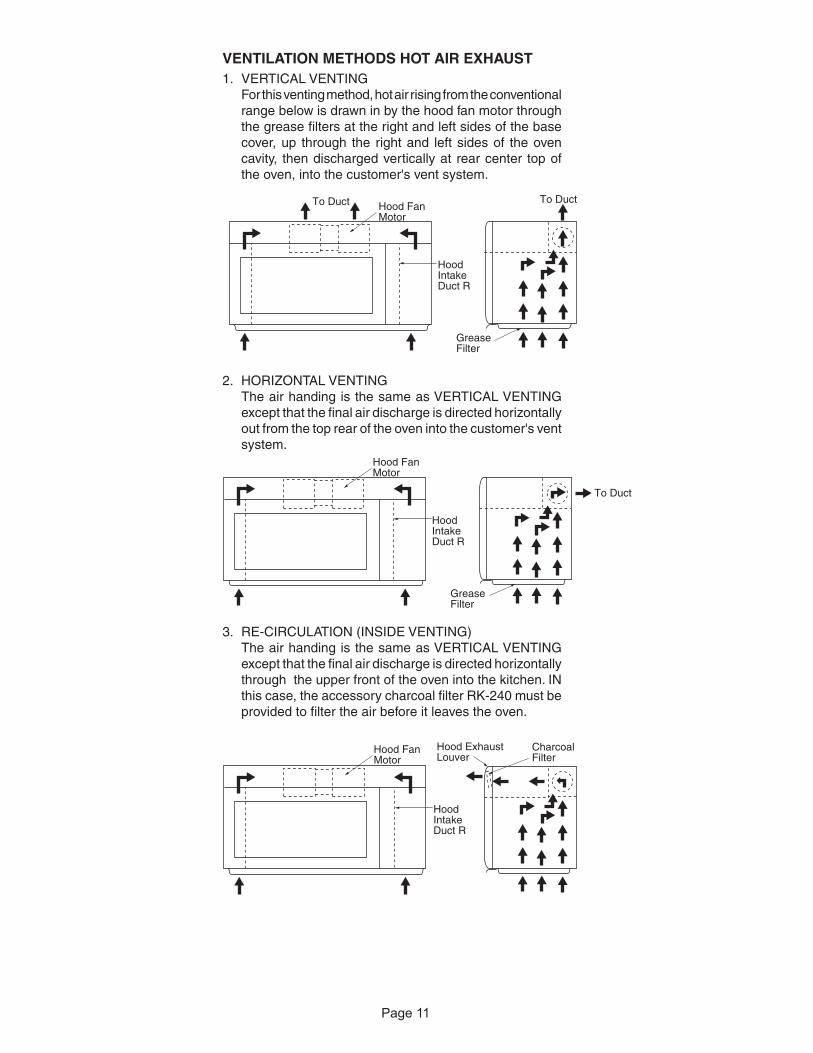
VENTILATION METHODS HOT AIR EXHAUST1. VERTICAL VENTING
For this venting method, hot air rising from the conventional range below is drawn in by the hood fan motor through the grease filters at the right and left sides of the base cover, up through the right and left sides of the oven cavity, then discharged vertically at rear center top of the oven, into the customer's vent system.
2. HORIZONTAL VENTINGThe air handing is the same as VERTICAL VENTING except that the final air discharge is directed horizontally out from the top rear of the oven into the customer's vent system.
3. RE-CIRCULATION (INSIDE VENTING)The air handing is the same as VERTICAL VENTING except that the final air discharge is directed horizontally through the upper front of the oven into the kitchen. IN this case, the accessory charcoal filter RK-240 must be provided to filter the air before it leaves the oven.
To DuctTo Duct
GreaseFilter
HoodIntakeDuct R
Hood Fan Motor
GreaseFilter
To Duct
HoodIntakeDuct R
Hood Fan Motor
HoodIntakeDuct R
Hood Exhaust Louver
Hood Fan Motor
CharcoalFilter
FMV157GSFMV157GBFMV157GMFMV157GQFMV157GC

Page 1211
SCHEMATICNOTE: CONDITION OF OVEN1. DOOR CLOSED.2. COOKING TIME PROGRAMMED.3. VARIABLE COOKING CONTROL
"HIGH".
Figure O-2. Oven Schematic-Cooking Condition
Figure O-1. Oven Schematic-Off Condition
SCHEMATICNOTE: CONDITION OF OVEN1. DOOR CLOSED.2. CLOCK APPEARS ON DISPLAY.
FMV157GSFMV157GBFMV157GMFMV157GQFMV157GC

Page 1312
DESCRIPTION AND FUNCTION OF COMPONENTS
vapors given off from the heating foods. It is then exhausted through the exhausting air vents at the oven cavity.
HOOD FAN MOTORThe hood fan motor is a two-speeds, single-phase, double pole induction type, requiring a hood fan capacitor. It is located outside the upper rear part of the oven cavity, is to remove, from around the oven, hot air rising from the conventional electric or gas range over which it is installed. This air is then expelled either vertically or horizontally through the customer supplied duct system, or discharged back into the kitchen.
HOOD LAMPThe hood lamps are mounted at the hood lamp angle on the base cover. The hood lamps can be turned off and on
Latch hook
Primary interlock switch
Latch heads
Monitor switch
Door sensing switch
Door
DOOR OPEN MECHANISMThe door is opened by pulling the door handle, refer to the Figure D-1.
CAUTION: BEFORE REPLACING A BLOWN MONITOR FUSE TEST THE DOOR SENSING SWITCH, SECONDARY INTERLOCK RELAY (RY2), RE-LAY (RY1), PRIMARY INTERLOCK SWITCH AND MONITOR SWITCH FOR PROPER OPERATION. (REFER TO CHAPTER "TEST PROCEDURE").
NOTE: MONITOR FUSE AND MONITOR SWITCH ARE REPLACED AS AN ASSEMBLY.
THERMAL CUT-OUT (HOOD )This thermal cut-out located on the right base plate. It is designed to automatically turn on the hood fan motor whenever the hot air rising from the conventional range below causes the temperature at the thermal cut-out to rise to158OF (70OC) or higher, thus removing this hot air from around microwave oven. When the temperature around the thermal cut-out drops to 104OF (40OC) or lower, the thermal cut-out shuts off the hood fan motor.
THERMAL CUT-OUT (CAVITY )This thermal cut-out is located on the top of the oven cavity. It is designed to prevent damage to the oven unit if the food in the oven catches fire due to overheating produced by improper setting of cooking time or failure of control unit.Under normal operation, the thermal cut-out remains closed. However, the thermal cut-out will open at 230OF (110OC)causing the oven to shut down.
TURNTABLE MOTORThe turntable motor rotates the turntable located on the bottom of the oven cavity, so that the foods on the turnta-ble cook evenly during cooking. Turntable will turn in either
COOLING FAN MOTORThe cooling fan motor drives a blade which draws external cool air. This cool air is directed through the air vanes sur-rounding the magnetron and cools the magnetron. This air is channelled through the oven cavity to remove steam and
Figure D-1. Door Open Mechanism
DOOR SENSING SWITCH, PRIMARY INTERLOCK SWITCHThe primary interlock switch is mounted in the upper positionof the latch hook, the door sensing switch in the primary interlock system is mounted in the lower position of the latch hook is mounted on upper position of the latch hook. They are activated by the latch heads on the door. When the door is opened, the switches interrupt the circuit to all components. A cook cycle cannot take place until the door is firmly closed thereby activating both interlock switches. The primary interlock system consists of the door sensing switch and secondary interlock relay located on the control circuit board.
MONITOR SWITCHThe monitor switch is activated (the contacts opened) by the latch head on the door while the door is closed. The switch is intended to render the oven inoperative, by means of blowing the monitor fuse, when the contacts of the second-ary interlock relay (RY2) and primary interlock switch fail to open when the door is opened.
Functions:1. When the door is opened, the monitor switch contact
close (to the ON condition) due to their being normally closed. At this time the secondary interlock relay (RY2), primary interlock switch are in the OFF condition (contacts open) due to their being normally open contact switches. And the contacts of relay (RY1) are in the ON condition (contacts close).
2. As the door goes to a closed position, the monitor switch contacts are first opened and then the door sensing switch and the primary interlock switch contacts close. (On opening the door, each of these switches operate inversely.)
3. If the door is opened, and the secondary interlock relay (RY2) and primary interlock switch contacts fail to open, the monitor fuse blows simultaneously with closing of the
direction.
FMV157GSFMV157GBFMV157GMFMV157GQFMV157GC

Page 1413
TROUBLESHOOTING GUIDE
Never touch any part in the circuit with your hand or an uninsulated tool while the power supply is con-nected.
When troubleshooting the microwave oven, it is helpful to follow the Sequence of Operation in performing the checks. Many of the possible causes of trouble will require that a specific test be performed. These tests are given a procedure letter which will be found in the "Test Procedure "section.
IMPORTANT: If the oven becomes inoperative because of a blown monitor fuse, check the monitor switch, relay (RY1)secondary interlock relay (RY2), door sensing switch and primary interlock switch before replacing the moni-tor fuse. If the monitor fuse is replaced, the monitor switch must also be replaced. Use part FFS-BA016/KITas an assembly.
IMPORTANT: Whenever troubleshooting is performed with the power supply cord disconnected. It may in, some cases, be necessary to connect the power supply cord after the outer case has been removed, in this event,1. Disconnect the power supply cord, and then remove outer case.2. Open the door and block it open.3. Discharge high voltage capacitor.4. Disconnect the leads to the primary of the power transformer.5. Ensure that the leads remain isolated from other components and oven chassis by using insulation
tape.6. After that procedure, reconnect the power supply cord.
When the testing is completed1. Disconnect the power supply cord, and then remove outer case.2. Open the door and block it open.3. Discharge high voltage capacitor.4. Reconnect the leads to the primary of the power transformer.5. Reinstall the outer case (cabinet).6. Reconnect the power supply cord after the outer case is installed.
FMV157GSFMV157GBFMV157GMFMV157GQFMV157GC

Page 1514
CK = Check / RE = Replace
POSSIBLE CASE ANDDEFECTIVE PARTS
PR
OB
LEM
TES
TP
RO
CE
DU
RE
CO
ND
ITIO
N
OF
FC
ON
DIT
ION
IDLE
CO
ND
ITIO
N
MIC
RO
WAV
EC
OO
KIN
GC
ON
DIT
ION
Hom
efu
sebl
ows
whe
npo
wer
cord
ispl
ugge
din
tow
all r
ecep
tacl
e.M
onito
rfu
sebl
ows
whe
npo
wer
cord
ispl
ugge
din
tow
all r
ecep
tacl
e.D
ispl
aydo
esno
till
umin
ate
whe
npo
wer
cord
isfir
stpl
ugge
din
tow
all
rece
ptac
le.
Dis
play
does
not
oper
ate
prop
erly
whe
nS
TO
P/C
LEA
Rke
yis
touc
hed.
(The
time
ofda
ysh
ould
appe
aron
the
disp
lay
with
beep
soun
ddu
ring
norm
alco
nditi
on.)
Ove
nla
mp
does
not l
ight
with
door
isop
ened
.H
ood
fan
mot
orop
erat
esw
hen
pow
erco
rdis
first
plug
ged
into
wal
lre
cept
acle
.T
empe
ratu
reof
oven
base
seem
sm
ore
than
140û
F(6
0ûC
)be
caus
eof
oper
atio
nof
the
rang
ebe
low
.B
utho
odfa
nm
otor
does
not
turn
onau
tom
atic
ally
.(N
orm
ally
,fo
odfa
nm
otor
shou
ldbe
oper
atin
gat
low
spee
d.)
Hoo
dlig
hts
dono
ttu
rnon
whe
nW
OR
KLI
GH
Tpa
dor
NIG
HT
LIG
HT
pad
ispr
esse
d.H
ood
fan
mot
ordo
esno
t rot
ate
atal
l with
touc
hed
FA
NH
I/LO
pad.
Spe
edof
the
hood
fan
mot
ordo
esno
tch
ange
whe
nth
eF
AN
HI/L
Opa
dis
touc
hed
for
this
func
tion.
Ove
nla
mp
does
not
light
inco
okcy
cle.
(But
itdo
eslig
htw
hen
door
isop
ened
.)F
anm
otor
does
not o
pera
te. (
Ove
nla
mp
and
turn
tabl
em
otor
oper
ate.
)T
urnt
able
mot
ordo
esno
top
erat
e(O
ven
lam
plig
hts
and
fan
mot
orop
erat
e.)
Ove
ndo
esno
t go
into
cook
cycl
ew
hen
ST
AR
Tpa
dis
touc
hed
Ove
nse
ems
tobe
oper
atin
gbu
tlit
tleor
nohe
atis
prod
uced
inov
enlo
ad.
(Foo
din
com
plet
ely
cook
edor
not c
ooke
dat
all a
t end
ofco
okcy
cle.
)O
ven
goes
into
aco
okcy
cle
but
extr
emel
yun
even
heat
ing
ispr
oduc
edin
oven
load
(foo
d).
Var
iabl
eco
okin
gdo
esno
top
erat
epr
oper
lyex
cept
Coo
king
Pow
er10
(P-
HI)
mod
e.F
unct
ion
ofC
OM
PU
DE
FR
OS
Tdo
esno
t ope
rate
prop
erly
.S
tirre
rm
otor
does
not o
pera
te. (
Oth
erpa
rts
oper
ate.
)O
ven
goes
into
CO
MP
UD
EF
RO
ST
but f
ood
isno
t def
rost
edw
ell.
CK LOW VOLTAGECK NO POWER AT OUTLETRE SHORTED IN POWER CORDCK OPENED OR SHORTED WIRINGCK HOOD MOTOR CAPACITORRE HOOD LAMP OR SOCKETCK TURNTABLE OFF CONDITIONRE TURNTABLE MOTORRE FAN MOTORRE OVEN LAMP OR SOCKET
FOIL PATERN ON P.W.B.O
N RELAY (RY-5)N RELAY (RY-4)N RELAY (RY-3)N RELAY (RY-2)N RELAY (RY-1)M KEY UNIT
L CONTROL UNITK HOOD FAN MOTORJ HOOD HERMAL CUT-OUTI MONITOR FUSEH MONITOR SWITCHG SECONDARY INTERLOCK SYSTEMF PRIMARY INTERLOCK SWITCHE TEMPERATURE FUSE OR THERMAL CUT-OUTD HIGH VOLTAGE CAPACITORC H.V. RECTIFIERB POWER TRANSFORMERA MAGNETRON
The
oven
stop
san
d"E
RR
OR
"is
disp
laye
dor
does
not
end
durin
gS
enso
rC
ooki
ngco
nditi
on. (
Ove
ndo
esno
t shu
t off
afte
ra
cup
ofw
ater
isbo
iling
byS
enso
rC
ooki
ng.)
Ove
nst
ops
at32
seco
nds
afte
rst
artin
g.
SE
NS
OR
CO
OK
ING
CO
ND
ITIO
N
FMV157GSFMV157GBFMV157GMFMV157GQFMV157GC

Page 1615
B POWER TRANSFORMER TEST
TEST PROCEDURESPROCEDURE
LETTER COMPONENT TEST
1. Disconnect the power supply cord, and then remove outer case.2. Open the door and block it open.3. Discharge high voltage capacitor.4. To test for an open filament, isolate the magnetron from the high voltage circuit. A continuity check
across the magnetron filament leads should indicate less than 1 ohm.5. To test for a shorted magnetron, connect the ohmmeter leads between the magnetron filament leads
and chassis ground. This test should indicate an infinite resistance. If there is little or no resistance the magnetron is grounded and must be replaced.
6. Reconnect all leads removed from components during testing.7. Reinstall the outer case (cabinet).8. Reconnect the power supply cord after the outer case is installed.9. Run the oven and check all functions.
MICROWAVE OUTPUT POWERThe following test procedure should be carried out with the microwave oven in a fully assembled condi-tion (outer case fitted).
HIGH VOLTAGES ARE PRESENT DURING THE COOK CYCLE, SO EXTREME CAUTION SHOULD BE OBSERVED.
Power output of the magnetron can be measured by performing a water temperature rise test. This test should only be used if above tests do not indicate a faulty magnetron and there is no defect in the following components or wiring: silicon rectifier, high voltage capacitor and power transformer. This test will require a 16 ounce (453cc) measuring cup and an accurate mercury thermometer or thermocouple type temperature tester. For accurate results, the following procedure must be followed carefully:
1. Fill the measuring cup with 16 oz. (453cc) of tap water and measure the temperature of the water with a thermometer or thermocouple temperature tester. Stir the thermometer or thermocouple through the water until the temperature stabilizes. Record the temperature of the water.
2. Place the cup of water in the oven. Operate oven at POWER 10(HIGH) selecting more than 60 seconds cook time. Allow the water to heat for 60 seconds, measuring with a stop watch, second hand of a watch or the digital read-out countdown.
3. Remove the cup from the oven and again measure the temperature, making sure to stir the thermometer or thermocouple through the water until the maximum temperature is recorded.
4. Subtract the cold water temperature from the hot water temperature. The normal result should be 29.2 to 54.2οF(16.2 to 30.1οC) rise in temperature. If the water temperatures are accurately measured and tested for the required time period the test results will indicate if the magnetron tube has low power output (low rise in water temperature) which would extend cooking time or high power output (high rise in water temperature) which would reduce cooking time. Because cooking time can be adjusted to compensate for power output, the magnetron tube assembly should be replaced only if the water temperature rise test indicates a power output well beyond the normal limits. The test is only accurate if the power supply line voltage is 120 volts and the oven cavity is clean.
A MAGNETRON ASSEMBLY TEST
1. Disconnect the power supply cord, and then remove outer case.2. Open the door and block it open.3. Discharge high voltage capacitor.4. Disconnect the primary input terminals and measure the resistance of the transformer with an
ohmmeter. Check for continuity of the coils with an ohmmeter. On the R x 1 scale, the resistance of the primary coil should be less than 1 ohm and the resistance of the high voltage coil should be approximately 83 ohms; the resistance of the filament coil should be less than 1 ohm.
5. Reconnect all leads removed from components during testing.6. Reinstall the outer case (cabinet).7. Reconnect the power supply cord after the outer case is installed.8. Run the oven and check all functions.
FMV157GSFMV157GBFMV157GMFMV157GQFMV157GC

Page 1716
TEST PROCEDURESPROCEDURE
LETTER COMPONENT TEST
1. Disconnect the power supply cord, and then remove outer case.2. Open the door and block it open.3. Discharge high voltage capacitor.4. If the capacitor is open, no high voltage will be available to the magnetron. Disconnect input leads
and check for short or open between the terminals using an ohmmeter.Checking with a high ohm scale, if the high voltage capacitor is normal, the meter will indicate continuity for a short time and should indicate an open circuit once the capacitor is charged. If the above is not the case, check the capacitor with an ohmmeter to see if it is shorted between either of the terminals and case. If it is shorted, replace the capacitor.
5. Reconnect all leads removed from components during testing.6. Reinstall the outer case (cabinet).7. Reconnect the power supply cord after the outer case is installed.8. Run the oven and check all functions.
D HIGH VOLTAGE CAPACITOR TEST
E CAVITY THERMAL CUT-OUT TEST
C HIGH VOLTAGE RECTIFIER TEST1. Disconnect the power supply cord, and then remove outer case.2. Open the door and block it open.3. Discharge high voltage capacitor.4. Isolate the rectifier from the circuit. Using the highest ohm scale of the meter, read the resistance
across the terminals and observe, reverse the leads to the rectifier terminals and observe meter reading. If a short is indicated in both directions, or if an infinite resistance is read in both directions, the rectifier is probably defective and should be replaced.
5. Reconnect all leads removed from components during testing.6. Reinstall the outer case (cabinet).7. Reconnect the power supply cord after the outer case is installed.8. Run the oven and check all functions.
NOTE: Be sure to use an ohmmeter that will supply a forward bias voltage of more than 6.3 volts.
(HIGH VOLTAGES ARE PRESENT AT THE HIGH VOLTAGE TERMINAL, SO DO NOT ATTEMPT TO MEASURE THE FILAMENT AND HIGH VOLTAGE.)
1. Disconnect the power supply cord, and then remove outer case.2. Open the door and block it open.3. Discharge high voltage capacitor.4. A continuity check across the thermal cut-out terminals should indicate a closed circuit unless the
temperature of the thermal cut-out reaches approximately 230OF(110OC). An open thermal cut-out indicates overheating of the oven, exchange the oven thermal cut-out and check inside of oven cavity and for improper setting of cooking time or operation of control unit. Check for restricted air flow through the vent holes of the oven cavity, especially the cooling fan and air guide.
5. Reconnect all leads removed from components during testing.6. Reinstall the outer case (cabinet).7. Reconnect the power supply cord after the outer case is installed.
MAGNETRON TEMPERATURE FUSE TEST1. Disconnect the power supply cord, and then remove outer case.2. Open the door and block it open.3. Discharge high voltage capacitor.4. A continuity check across the magnetron temperature fuse terminals should indicate a closed circuit
unless the temperature of the magnetron temperature fuse reaches approximately 302OF(150OC). An open magnetron temperature fuse indicates overheating of the magnetron. Check for restricted air flow to the magnetron, especially the cooling fan air guide.
FMV157GSFMV157GBFMV157GMFMV157GQFMV157GC

Page 1817
TEST PROCEDURESPROCEDURE
LETTER COMPONENT TEST
1. Disconnect the power supply cord, and then remove outer case.2. Open the door and block it open.3. Discharge high voltage capacitor.4. Isolate the switch and connect the ohmmeter to the common (COM.) and normally open (NO) terminal
of the switch. The meter should indicate an open circuit with the door open and a closed circuit with the door closed. If improper operation is indicated, replace the secondary interlock switch.
5. Reconnect all leads removed from components during testing.6. Reinstall the outer case (cabinet).7. Reconnect the power supply cord after the outer case is installed.8. Run the oven and check all functions.5. Reconnect all leads removed from
components during testing.6. Reinstall the outer case (cabinet).7. Reconnect the power supply cord after
the outer case is installed.8. Run the oven and check all functions.
F PRIMARY INTERLOCK SWITCH TEST
CAUTION: IF THE TEMPERATURE FUSE INDICATES AN OPEN CIRCUIT AT ROOM TEMPERATURE, REPLACE TEMPERATURE FUSE.
G PRIMARY INTERLOCK SYSTEM TEST
DOOR SENSING SWITCH1. Disconnect the power supply cord, and then remove outer case.2. Open the door and block it open.3. Discharge high voltage capacitor.4. Isolate the switch and connect the ohmmeter to the common (COM.) and normally open (NO)
terminal of the switch. The meter should indicate an open circuit with the door open and a closed circuit with the door closed. If improper operation is indicated, replace the door sensing switch.
5. Reconnect all leads removed from components during testing.6. Reinstall the outer case (cabinet).7. Reconnect the power supply cord after the outer case is installed.8. Run the oven and check all functions.
NOTE: If the door sensing switch contacts fail in the open position and the door is closed, the cooling fan motor, stirrer motor and oven light will be activated by RY1.
5. Reconnect all leads removed from components during testing.6. Reinstall the outer case (cabinet).7. Reconnect the power supply cord after the outer case is installed.8. Run the oven and check all functions.
CAUTION: IF THE TEMPERATURE FUSE INDICATES AN OPEN CIRCUIT AT ROOM TEMPERATURE, REPLACE TEMPERATURE FUSE.
FMV157GSFMV157GBFMV157GMFMV157GQFMV157GC

Page 1918
TEST PROCEDURESPROCEDURE
LETTER COMPONENT TEST
H MONITOR SWITCH TEST
SECONDARY INTERLOCK RELAY (RY2)1. Disconnect the power supply cord, and then remove outer case.2. Open the door and block it open.3. Discharge high voltage capacitor.4. Disconnect two (2) wire leads from the male tab terminals of the Secondary Interlock Relay. Check
the state of the relay contacts using a ohmmeter. The relay contacts should be open. If the relay contacts are closed, replace the circuit board entirely or the relay itself.
5. Reconnect all leads removed from components during testing.6. Reinstall the outer case (cabinet).7. Reconnect the power supply cord after the outer case is installed.8. Run the oven and check all functions.
plate of the oven cavity with the door opened (in this condition the plunger of the monitor switch is pushed in), the meter should indicate an open circuit. If improper operation is indicated, the switch may be defective. After testing the monitor switch, reconnect the wire lead to the monitor switch (COM) terminal and check the continuity of the monitor circuit.
Doorsensing switchh Monitor Switch
Screw Driver
Ohmmeter
White / White
1. Disconnect the power supply cord, and then remove outer case.2. Open the door and block it open.3. Discharge high voltage capacitor.4. Before performing this test, make sure that the secondary interlock switch and the primary interlock
relay are operating properly, according to the above Switch Test Procedure. Disconnect the wire lead from the monitor switch (COM) terminal. Check the monitor switch operation by using the ohmmeter as follows. When the door is open, the meter should indicate a closed circuit. When the monitor switch actuator is pushed by a screw driver through the lower latch hole on the front plate of the oven cavity with the door opened (in this condition the plunger of the monitor switch is pushed in), the meter should indicate an open circuit. If improper operation is indicated, the switch may be defective. After testing the monitor switch, reconnect the wire lead to the monitor switch (COM) terminal and check the continuity of the monitor circuit.
5. Reconnect all leads removed from components during testing.6. Reinstall the outer case (cabinet).7. Reconnect the power supply cord after the outer case is installed.8. Run the oven and check all functions. of the oven cavity with the door opened (in this condition the plunger of the monitor switch is pushed
in), the meter should indicate an open circuit. If improper operation is indicated, the switch may be defective. After testing the monitor switch, reconnect the wire lead to the monitor switch (COM) terminal and check the continuity of the monitor circuit.
5. Reconnect all leads removed from components during testing.6. Reinstall the outer case (cabinet).7. Reconnect the power supply cord after the outer case is installed.8. Run the oven and check all functions.
FMV157GSFMV157GBFMV157GMFMV157GQFMV157GC

Page 209
TEST PROCEDURESPROCEDURE
LETTER COMPONENT TEST J HOOD THERMAL CUT-OUT TEST
. Disconnect the power supply cord, and then remove outer case.2. Open the door and block it open.3. Discharge high voltage capacitor.4. A continuity check across the thermal cut-out terminals should indicate an open circuit unless the
temperature of the thermal cut-out reaches approximately 158½F(70½C) or more. At that temperature, the contacts will close. The thermal cut-out opens automatically at approximately 104½F(40½C).
5. Reconnect all leads removed from components during testing.6. Reinstall the outer case (cabinet).7. Reconnect the power supply cord after the outer case is installed.8. Run the oven and check all functions.
K HOOD FAN MOTOR TEST . Disconnect the power supply cord, and then remove outer case.
2. Open the door and block it open.3. Discharge high voltage capacitor.4. If the motor does not turn, touch the FAN button once and check voltage between pins "" and "2"
(Blue and Black wires) of the 6 pin connector. If 20 Volts appear and the hood capacitor is good, replace the hood fan assembly. If 20 Volts does not appear, check the motor circuit. The resistance values of motor terminals are as follows:
5. Reconnect all leads removed from components during testing.6. Reinstall the outer case (cabinet).7. Reconnect the power supply cord after the outer case is installed.8. Run the oven and check all functions.
Resistance between;
WHT() AND YLW (4) = 0Ω (Shorted)BLU (2) AND YLW (4) = 34ΩWHT() AND BLK (2) = 34ΩRED(5) AND WHT() = 77ΩRED(5) AND BLU (2) = 43ΩYLW(4) AND RED (5) = 77Ω
6-PIN CONNECTOROF HOOD FAN MOTOR
RED YLW
ORG BLU WHT
5
3 2 1
4
FMV157GSFMV157GBFMV157GMFMV157GQFMV157GC

Page 2120
TEST PROCEDURESPROCEDURE
LETTER COMPONENT TEST L TOUCH CONTROL PANEL ASSEMBLY TEST
The touch control panel consists of circuits including semiconductors such as LSI, ICs, etc. Therefore, unlike conventional microwave ovens, proper maintenance cannot be performed with only a voltmeter and ohmmeter. In this service manual, the touch control panel assembly is divided into two units, Con-trol Unit and Key Unit, and also the Control Unit is divided into two units, LSI Unit and Power Unit, and troubleshooting by unit replacement is described according to the symptoms indicated.Before testing,
1) Disconnect the power supply cord, and then remove outer case. Refer to procedure of " HOOD EXHAUST LOUVER REMOVAL ", " REMOVAL OF OVEN FROM WALL " and " OUTER CASE REMOVAL ".
2) Open the door and block it open.3) To discharge high voltage capacitor, wait for 60 seconds.4) Remove two (2) screws holding the hood intake duct R to the ovencavity top plate and the base
plate R. And remove the hood intake duct R. 5) Disconnect the leads to the primary of the power transformer.6) Ensure that these leads remain isolated from other components and oven chassis by using
insulation tape.1. Key Unit.
NOTE ;1) Check key unit ribbon connection before replacement.2) Reconnect all leads removed from components during testing.3) Re-install the hood intake duct R with two (2) screws.4) Re-install the outer case (cabinet).5) Reconnect the power supply cord after the outer case is installed.6) Run the oven and check all functions.
The following symptoms indicate a defective key unit.a) When touching the pads, a certain pad produces no signal at all.b) When touching a number pad, two figures or more are displayed.c) When touching the pads, sometimes a pad produces no signal.If the key unit is defective.1) Disconnect the power supply cord, and then remove outer case.2) Open the door and block it open.3) To discharge high voltage capacitor, wait for 60 seconds.4) Replace the key unit.5) Reconnect all leads removed from components during testing.6) Re-install the outer case (cabinet).7) Reconnect the power supply cord after the outer case is installed.8) Run the oven and check all functions.
2. Control Unit.The following symptoms indicate a defective control unit. Before replacing the control unit, perform the Key unit test (Procedure M) to determine if control unit is faulty.
2-1 In connection with pads.a) When touching the pads, a certain group of pads do not produce a signal.b) When touching the pads, no pads produce a signal.
2-2 In connection with indicatorsa) At a certain digit, all or some segments do not light up.b) At a certain digit, brightness is low.c) Only one indicator does not light. d) The corresponding segments of all digits do not light up; or they continue to light up.e) Wrong figure appears.f) A certain group of indicators do not light up.g) The figure of all digits flicker.
2-3 Other possible problems caused by defective control unit.a) Buzzer does not sound or continues to sound.b) Clock does not operate properly.c) Cooking is not possible.
FMV157GSFMV157GBFMV157GMFMV157GQFMV157GC

Page 2221
When testing is completed,1) Disconnect the power supply cord.2) Open the door and block it open.3) To discharge high voltage capacitor, wait for 60 seconds. 4) Reconnect all leads removed from components during testing.5) Re-install the hood intake duct R.6) Re-install the outer case (cabinet).7) Reconnect the power supply cord after the outer case is installed.8) Run the oven and check all functions.
TEST PROCEDURESPROCEDURE
LETTER COMPONENT TEST
N RELAY TEST
1. Disconnect the power supply cord.2. Open the door and block it open.3. To discharge high voltage capacitor, wait for 60 seconds.4. Remove the control panel assembly.5. If the display fails to clear when the CLEAR-OFF pad is depressed, first verify the flat ribbon cable is
making good contact, verify that the door sensing switch (stop switch) operates properly; that is the contacts are closed when the door is closed and open when the door is open. If the door sensing switch (stop switch) is good, disconnect the flat ribbon cable that connects the key unit to the control unit and make sure the door sensing switch is closed (either close the door or short the door sensing switch connecter). Use the Key unit matrix indicated on the control panel schematic and place a jumper wire between the pins that correspond to the CLEAR-OFF pad making momentary contact. If the control unit responds by clearing with a beep the key unit is faulty and must be replaced. If the control unit does not respond, it is faulty and must be replaced. If a specific pad does not respond, the above method may be used (after clearing the control unit) to determine if the control unit or key pad is at fault.
6. Reconnect all leads removed from components during testing.7. Re-install the control panel assembly.8. Reconnect the power supply cord.9. Run the oven and check all functions.
M KEY UNIT TEST
1. Disconnect the power supply cord, and then remove outer case. Refer to procedure of " HOOD EXHAUST LOUVER REMOVAL ", " REMOVAL OF OVEN FROM WALL " and " OUTER CASE REMOVAL ".
2. Open the door and block it open.3. To discharge high voltage capacitor, wait for 60 seconds.4. Remove the hood intake duct R.5. Disconnect the leads to the primary of the power transformer.6. Ensure that these leads remain isolated from other components and oven chassis by using insulation
tape.
G2
G1
G4
G 5
KEY UNIT
Cook
Reheat
Defrost
PowerLevel
TIMERCLOCK
Popcorn Light
Fan
1
2
4 5
3
8
6
9
0
7
G 6 G 7 G 8 G 9 G10 G11 G12
G3
ClearOff
STARTPlus 1 Min
G1
FMV157GSFMV157GBFMV157GMFMV157GQFMV157GC

Page 2322
TEST PROCEDURESPROCEDURE
LETTER COMPONENT TEST
7. After that procedure, re-connect the power supply cord.8. Check voltage between normal open terminal of the relay RY2 and the normal open terminal of the
relay RY1 on the control unit with an A.C. voltmeter.The meter should indicate 120 volts, if not check oven circuit.
RY1, RY2, RY4, and RY5 Relay Test These relays are operated by D.C. voltageCheck voltage at the relay coil with a D.C. voltmeter during the microwave cooking operation.
DC. voltage indicated Defective relay.DC. voltage not indicated Check diode which is connected to the relay coil. If diode
is good, control unit is defective.
RELAY SYMBOL OPERATIONAL VOLTAGE CONNECTED COMPONENTS
RY1 Approx. 26.6V D.C. Oven lamp / Fan motor / Turntable motor
RY2(COOK) Approx. 26.0V D.C. Power transformer
RY4 Approx. 26.6V D.C. Hood motor
RY3 Approx. 26.6V D.C. Hood lamp
9. Disconnect the power supply cord.10. Open the door and block it open.11. To discharge high voltage capacitor, wait for 60 seconds.12. Reconnect all leads removed from components during testing.13. Re-install the hood intake duct R.14. Re-install the outer case (cabinet).15. Reconnect the power supply cord after the outer case is installed.16. Run the oven and check all functions.
O DEFROST CENTER TEST(1) Open the door.(2) Place one cup of water in the center of the turntable tray in the oven cavity.(3) Close the door.(4) Touch the " DEFROST" pad once.(5) Touch the number pad "2".(6) Touch the number pad "5".(7) Touch the " START " button.(8) The oven is in Defrost center cooking condition.(9) The oven will operate as follows.
Menu 1ST STAGE 2ND STAGESteaks/Chops LEVEL TIME LEVEL TIME
0.5lbs 60% 57sec. 40% 17sec.
(8) If improper operation is indicated, the control unit is probably defective and should be checked.
To protect the electronic circuits, this model is provided with a fine foil pattern added to the primary on the PWB, this foil pattern acts as a fuse.1. Foil pattern check and repairs.
1) Disconnect the power supply cord.2) Open the door and block it open.3) To discharge high voltage capacitor, wait for 60 seconds.4) Remove the control unit, referring to the procedure of " CONTROL PANEL ASSEMBLY, CONTROL
UNIT AND KEY UNIT REMOVAL ".5) Follow the troubleshooting guide given below for repair.
P FOIL PATTERN ON THE PRINTED WIRING BOARD TEST
FMV157GSFMV157GBFMV157GMFMV157GQFMV157GC

Page 2423
CN
-A
VR
S1
P
T1
RY3(J1)
ac
d
b
7
TEST PROCEDURESPROCEDURE
LETTER COMPONENT TEST
STEPS OCCURRENCE CAUSE OR CORRECTION 1 Only pattern at "a" is broken. *Insert jumper wire J1 and solder.
2 Pattern at "a" and "b" are broken. *Insert the coil RCILF2003YAZZ between "c" and "d".
6) Make a visual inspection of the varistor. Check for burned damage and examine the transformer with a tester for the presence of layer short-circuit (check the primary coil resistance which is approximately 215Ω ± 10%). If any abnormal condition is detected, replace the defective parts.
7) Reconnect all leads removed from components during testing.8) Re-install the control unit to the control panel and re-install the control panel to the oven.9) Reconnect the power supply cord.
10) Run the oven and check all functions.2. Follow the troubleshooting guide given below, if indicator does not light up after above check and
repairs are finished.1) Disconnect the power supply cord, and then remove outer case. Refer to procedure of " HOOD
EXHAUST LOUVER REMOVAL ", " REMOVAL OF OVEN FROM WALL " and " OUTER CASE REMOVAL ".
2) Open the door and block it open.3) To discharge high voltage capacitor, wait for 60 seconds.4) Remove the hood intake duct R.5) Disconnect the leads to the primary of the power transformer.6) Ensure that these leads remain isolated from other components and oven chassis by using
insulation tape.7) After that procedure, re-connect the power supply cord.8) Follow the troubleshooting guide given below for repair.
STEPS OCCURRENCE CAUSE OR CORRECTION
The rated AC voltage is not present between 1 the normal open terminal of the relay RY2 and Check supply voltage and oven power cord. the normal open terminal of the relay RY1.
2 The rated AC voltage is present at primary Low voltage transformer or secondary circuit defective. side of low voltage transformer. Check and repair.
9) Disconnect the power supply cord.10) Open the door and block it open.11) To discharge high voltage capacitor, wait for 60 seconds.12) Reconnect all leads removed from components during testing.13) Re-install the hood intake duct R.14) Re-install the outer case (cabinet).15) Reconnect the power supply cord after the outer case is installed.16) Run the oven and check all functions.
FMV157GSFMV157GBFMV157GMFMV157GQFMV157GC

Page 2524
TEST PROCEDURESPROCEDURE
LETTER COMPONENT TEST Q NOISE FILTER TEST
1. Disconnect the power supply cord, and then remove outer case.2. Open the door and block it open.3. Discharge high voltage capacitor.4. Disconnect the leads to the primary of the power transformer.5. Using an ohm-meter, check between the terminals as described in the following table:
MEASURING POINT INDICATION OF OHM-METER
Between N and H Open Circuit
Between terminal N and LOAD Short Circuit
Between terminal H and LOAD Short Circuit
If incorrect readings are obtained, replace the noise filter.
6. Reconnect all leads removed from components during testing.7. Re-install the outer case (cabinet).8. Reconnect the power supply cord after the outer case is installed.9. Run the oven and check all functions.
NOISE FILTER UNIT
NOISE SUPPRESSION COIL
LINE CROSS CAPACITOR
RESISTOR
LINE BYPASS CAPACITORLINE BYPASS CAPACITOR
0.0033uF/ 250v0.0033uF/ 250v
LOADLOAD
HN
MONITORFUSE
FMV157GSFMV157GBFMV157GMFMV157GQFMV157GC
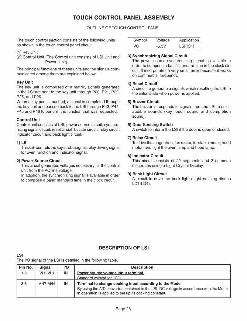
Page 2625
DESCRIPTION OF LSILSIThe I/O signal of the LSI is detailed in the following table.
Pin No. Signal I/O Description1-2 VL2-VL1 IN Power source voltage input terminal.
Standard voltage for LCD.
3-6 AN7-AN4 IN Terminal to change cooking input according to the Model. By using the A/D converter contained in the LSI, DC voltage in accordance with the Model
in operation is applied to set up its cooking constant.
TOUCH CONTROL PANEL ASSEMBLY
OUTLINE OF TOUCH CONTROL PANEL
Symbol Voltage Application
VC -5.3V LSI(IC1)
3) Synchronizing Signal CircuitThe power source synchronizing signal is available in order to compose a basic standard time in the clock cir-cuit. It incorporates a very small error because it works on commercial frequency.
4) Reset CircuitA circuit to generate a signals which resetting the LSI to the initial state when power is applied.
5) Buzzer CircuitThe buzzer is responds to signals from the LSI to emitaudible sounds (key touch sound and completion sound).
6) Door Sensing SwitchA switch to inform the LSI if the door is open or closed.
7) Relay CircuitTo drive the magnetron, fan motor, turntable motor, hood motor, and light the oven lamp and hood lamp.
8) Indicator CircuitThis circuit consists of 22 segments and 3 common electrodes using a Light Crystal Display.
9) Back Light CircuitA circuit to drive the back light (Light emitting diodes LD1-LD4).
The touch control section consists of the following unitsas shown in the touch control panel circuit.
(1) Key Unit (2) Control Unit (The Control unit consists of LSI Unit and
Power U nit)
The principal functions of these units and the signals com-municated among them are explained below.
Key UnitThe key unit is composed of a matrix, signals generated in the LSI are sent to the key unit through P20, P21, P22, P25, and P26.When a key pad is touched, a signal is completed through the key unit and passed back to the LSI through P43, P44, P45 and P46 to perform the function that was requested.
Control Unit Control unit consists of LSI, power source circuit, synchro-nizing signal circuit, reset circuit, buzzer circuit, relay circuit indicator circuit and back light circuit.
1) LSIThis LSI controls the key strobe signal, relay driving signal for oven function and indicator signal.
2) Power Source CircuitThis circuit generates voltages necessary for the control unit from the AC line voltage.In addition, the synchronizing signal is available in order to compose a basic standard time in the clock circuit.
FMV157GSFMV157GBFMV157GMFMV157GQFMV157GC
Page 27
26
Maximumoutput
70% ofmaximumoutput
H : GND
L : -5V
H : GND
L : -5V
ON
ON
OFF
OFF OFF
24 sec.
8 sec.
16.7 msec.
H : GND
L : -5V
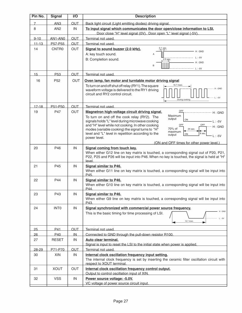
7 AN3 OUT Back light circuit (Light emitting diodes) driving signal.
8 AN2 IN To input signal which communicates the door open/close information to LSI. Door close "H" level signal (0V). Door open "L" level signal (-5V).
9-10 AN1-AN0 OUT Terminal not used.
11-13 P57-P55 OUT Terminal not used.
14 CNTR0 OUT Signal to sound buzzer (2.0 kHz). A: key touch sound.
B: Completion sound.
15 P53 OUT Terminal not used.
16 P52 OUT Oven lamp, fan motor and turntable motor driving signal To turn on and off shut off relay (RY1). The square
waveform voltage is delivered to the RY1 driving circuit and RY2 control circuit.
17-18 P51-P50 OUT Terminal not used.
19 P47 OUT Magnetron high-voltage circuit driving signal. To turn on and off the cook relay (RY2). The
signals holds "L" level during microwave cooking and "H" level while not cooking. In other cooking modes (variable cooking) the signal turns to "H" level and "L" level in repetition according to the power level.
(ON and OFF times for other power level.)
20 P46 IN Signal coming from touch key. When either G12 line on key matrix is touched, a corresponding signal out of P20, P21,
P22, P25 and P26 will be input into P46. When no key is touched, the signal is held at "H" level.
21 P45 IN Signal similar to P46. When either G11 line on key matrix is touched, a corresponding signal will be input into
P45.
22 P44 IN Signal similar to P46. When either G10 line on key matrix is touched, a corresponding signal will be input into
P44.
23 P43 IN Signal similar to P46. When either G9 line on key matrix is touched, a corresponding signal will be input into
P43.
24 INT0 IN Signal synchronized with commercial power source frequency. This is the basic timing for time processing of LSI.
25 P41 OUT Terminal not used.
26 P40 IN Connected to GND through the pull-down resistor R100.
27 RESET IN Auto clear terminal. Signal is input to reset the LSI to the initial state when power is applied.
28-29 P71-P70 OUT Terminal not used.
30 XIN IN Internal clock oscillation frequency input setting. The internal clock frequency is set by inserting the ceramic filter oscillation circuit with
respect to XOUT terminal.
31 XOUT OUT Internal clock oscillation frequency control output. Output to control oscillation input of XIN.
32 VSS IN Power source voltage: -5.0V. VC voltage of power source circuit input.
Pin No. Signal I/O Description
A
B
0.1 sec.
2.0 sec.
H : GND
L : -5V
H : GND
L : -5V
16.7 msec.
During cooking
H : GND
L : -5V
FMV157GSFMV157GBFMV157GMFMV157GQFMV157GC

Page 2827
34 P26 OUT Key strobe signal. Signal applied to touch-key section. A pulse signal is input to P43-P46 terminal while one
of G7 line keys on key matrix is touched.
35 P25 OUT Key strobe signal. Signal applied to touch-key section. A pulse signal is input to P43-P46 terminal while one
of G6 line keys on key matrix is touched.
36 P24 OUT Terminal not used.
37 P23 OUT Terminal not used.
38 P22 OUT Key strobe signal. Signal applied to touch-key section. A pulse signal is input to P43-P46 terminal while one
of G3 line keys on key matrix is touched.
39 P21 OUT Key strobe signal. Signal applied to touch-key section. A pulse signal is input to P43-P46 terminal while one
of G2 line keys on key matrix is touched.
40 P20 OUT Key strobe signal. Signal applied to touch-key section. A pulse signal is input to P43-P46 terminal while one
of G1 line keys on key matrix is touched.
41 P17 OUT Terminal not used.
42 P16 OUT Hood lamp driving signal. To turn on and off relay(RY5). " L " level: During
Hood lamp ON. "H" level: During Hood lamp OFF.
43 P15 OUT Terminal not used.
44 P14 OUT Hood motor driving signal. To turn on and off relay(RY4). "L" level: During
Hood motor ON. "H" level: During Hood motor OFF.
45-47 P13-P11 OUT Terminal not used.
48-50 SEG24-SEG22 OUT Terminal not used.
51-72 SEG21-SEG0 OUT Segment data signal. Connected to LCD.
The relation between signals are as follows: LSI signal (Pin No.) LCD (Pin No.) LSI signal (Pin No.) LCD (Pin No.) SEG 21 (51) -------------------- SEG21 ( 1) SEG 10 (62) --------------------- SEG10 (12) SEG 20 (52) -------------------- SEG20 ( 2) SEG 9 (63) ---------------------- SEG 9 (13) SEG 19 (53) -------------------- SEG19 ( 3) SEG 8 (64) ---------------------- SEG 8 (14) SEG 18 (54) -------------------- SEG18 ( 4) SEG 7 (65) ---------------------- SEG 7 (15) SEG 17 (55) -------------------- SEG17 ( 5) SEG 6 (66) ---------------------- SEG 6 (16) SEG 16 (56) -------------------- SEG16 ( 6) SEG 5 (67) ---------------------- SEG 5 (17) SEG 15 (57) -------------------- SEG15 ( 7) SEG 4 (68) ---------------------- SEG 4 (18) SEG 14 (58) -------------------- SEG14 ( 8) SEG 3 (69) ---------------------- SEG 3 (19) SEG 13 (59) -------------------- SEG13 ( 9) SEG 2 (70) ---------------------- SEG 2 (20) SEG 12 (60) --------------------SEG12 (10) SEG 1 (71) ---------------------- SEG 1 (21) SEG 11 (61) --------------------SEG11 (11) SEG 0 (72) ---------------------- SEG 0 (22)
73/74 VCC/VREF IN Connected to GND.
75 AVSS IN Connected to VC.
76 COM3 OUT Terminal not used.
77 COM2 OUT Common data signal: COM2. Connected to LCD signal COM2.
78 COM1 OUT Common data signal: COM1. Connected to LCD signal COM1.
79 COM0 OUT Common data signal: COM0. Connected to LCD signal COM0.
80 VL3 IN Power source voltage input terminal. Standard voltage for LCD.
Pin No. Signal I/O Description
ON
OFFH : GND
L
ON
OFFH : GND
L
FMV157GSFMV157GBFMV157GMFMV157GQFMV157GC
Page 2928
1. Precautions for Handling Electronic ComponentsThis unit uses CMOS LSI in the integral part of the circuits. When handling these parts, the following precautions should be strictly followed. CMOS LSI have extremely high impedance at its input and output terminals. For this reason, it is easily influenced by the surrounding high voltage power source, static electricity charge in clothes, etc. and sometimes it is not fully protected by the built-in protection circuit.In order to protect CMOS LSI.
1) When storing and transporting, thoroughly wrap them in aluminium foil. Also wrap all PW boards containing them in aluminium foil.
2) When soldering, ground the technician as shown in the figure and use grounded soldering iron and work table.
2. Shapes of Electronic Components
3. Servicing of Touch Control PanelWe describe the procedures to permit servicing of the touch control panel of the microwave oven and the precautions you must take when doing so. To perform the servicing, power to the touch control panel is available either from the power line of the oven itself or from an external power source.
(1) Servicing the touch control panel with power supply of the oven:CAUTION: THE HIGH VOLTAGE TRANSFORMER OF THE MICROWAVE OVEN IS STILL LIVE DURING SERVICING AND PRESENTS A HAZARD.Therefore, before checking the performance of the touch control panel,1) Disconnect the power supply cord, and then remove
outer case.2) Open the door and block it open.3) Discharge high voltage capacitor.4) Disconnect the leads to the primary of the power
transformer.5) Ensure that these leads remain isolated from other
components and oven chassis by using insulation tape.
6) After that procedure, re-connect the power supply cord.
After checking the performance of the touch control panel,1) Disconnect the power supply cord.2) Open the door and block it open.3) Re-connect the leads to the primary of the power
transformer.4) Re-install the outer case (cabinet).5) Re-connect the power supply cord after the outer
case is installed.6) Run the oven and check all functions.
A. On some models, the power supply cord between the touch control panel and the oven itself is so short that the two can’t be separated. For those models, check and repair all the controls (sensor-related ones included) of the touch control panel while keeping it connected to the oven.
B. On some models, the power supply cord between the touch control panel and the oven proper is long enough that they may be separated from each other. For those models, it is possible to check and repair the controls of the touch control panel while keeping it apart from the oven proper; in this case you must short both ends of the door sensing switch (on PWB) of the touch control panel with a jumper, which activates an operational state that is equivalent to the oven door being closed. As for the sensor-related controls of the touch control panel, checking them is possible if dummy resistor(s) with resistance equal to that of the controls are used.
(2) Servicing the touch control panel with power supply from an external power source:Disconnect the touch control panel completely from the oven proper, and short both ends of the door sensing switch (on PWB) of the touch control panel, which activates an operational state that is equivalent to the oven door being closed. Connect an external power source to the power input terminal of the touch control panel, then it is possible to check and repair the controls of the touch control panel it is also possible to check the sensor-related controls of the touch control panel by using the dummy resistor(s).
4. Servicing ToolsTools required to service the touch control panel assembly.1) Soldering iron: 30W
(It is recommended to use a soldering iron with a grounding terminal.)
2) Oscilloscope: Single beam, frequency range: DC-10MHz type or more advanced model.
3) Others: Hand tools
5. Other Precautions1) Before turning on the power source of the control
unit, remove the aluminium foil applied for preventing static electricity.
2) Connect the connectors of the key unit to the control unit being sure that the lead wires are not twisted.
3) After aluminium foil is removed, be careful that abnormal voltage due to static electricity etc. is not applied to the input or output terminals.
4) Attach connectors, electrolytic capacitors, etc. to PWB, making sure that all connections are tight.
SERVICING
approx. 1M ohm
TransistorKRC243M
EC B
FMV157GSFMV157GBFMV157GMFMV157GQFMV157GC

Page 3029
result in severe, possibly fatal, electric shock.(Example)High Voltage Capacitor, Power Transformer, Magnetron, High Voltage Rectifier Assembly, High Voltage Harness etc..
WARNING: Avoid possible exposure to microwave energy. Please follow the instructions below before operat-ing the oven.
WARNING AGAINST HIGH VOLTAGE:Microwave ovens contain circuitry capable of producing very high voltage and current, contact with following parts may
COMPONENT REPLACEMENT AND ADJUSTMENT PROCEDURE
To prevent an electric shock, take the following pre-cautions.1. Before wiring,
1) Disconnect the power supply cord.2) Open the door block it open.3) Discharge the high voltage capacitor and wait for 60
seconds.2. Don’t let the wire leads touch to the followiong parts;
1) High voltage parts:Magnetron, High voltage transformer, High voltage capacitor and High voltage rectifier assembly.
2) Hot parts:Oven lamp, Magnetron, High voltage transformer and Oven cavity.
WARNING FOR WIRING
1. Disconnect the power supply cord.2. Make sure that a definite” click” can be heard when
the microwave oven door is unlatched. (Hold the door in a closed position with one hand, then push the door open button with the other, this causes the latch leads to rise, it is then possible to hear a “click’ as the door switches operate.)
3. Visually check the door and cavity face plate for damage (dents, cracks, signs of arcing etc.).
Carry out any remedial work that is necessary before operating the oven.Do not operate the oven if any of the following conditions exist;
1. Door does not close firmly.2. Door hinge, support or latch hook is damaged.3. The door gasket or seal is damaged.4. The door is bent or warped.5. There are defective parts in the door interlock
system.6. There are defective parts in the microwave generating
and transmission assembly.7. There is visible damage to the oven.
Do not operate the oven:1. Without the RF gasket (Magnetron).2. If the wave guide or oven cavity are not intact.3. If the door is not closed.4. If the outer case (cabinet) is not fitted.
3) Sharp edge:Bottom plate, Oven cavity, Waveguide flange, Chassis support and other metallic plate.
4) Movable parts (to prevent a fault)Fan blade, Fan motor, Switch, Open lever, Open button.
3. Do not catch the wire leads in the outer case cabinet.4. Insert the positive lock connector until its pin is locked
and make sure that the wire leads do not come off even if the wire leads are pulled.
5. To prevent an error function, connect the wire leads correctly, referring to the Pictorial Diagram.
Please refer to ‘OVEN PARTS, CABINET PARTS, CONTROL PANAL PARTS, DOOR PARTS’, when carrying out any of the following removal procedures:
THE FOLLOWING ADJUSTMENTS OR COMPONENT REPLACEMENT CAN BE PERFORMED WITHOUT REMOVING THE OVEN FROM THE WALL
1. Hood lamps, sockets, grease filter and charcoal filter.2. Base cover and hood lamp glass assembly.3. Turntable motor.
4. Hood exhaust louver.5. Control panel assembly or components.
HOOD EXHAUST LOUVER REMOVAL
1. Disconnect the power supply cord.2. Open the door and block it open.3. To discharge the high voltage capacitor, wait for 60
seconds.4. Remove the two (2) screws on the top holding the hood
exhaust louver to the oven cavity front face plate.
FMV157GSFMV157GBFMV157GMFMV157GQFMV157GC

Page 31
30
REMOVAL OF OVEN FROM WALL (Two persons recommended to remove the oven)1. Disconnect the power supply cord, and uncoil the power supply cord.2. To discharge the high voltage capacitor, wait for 60
seconds.3. Remove the turntable tray and support from the oven
cavity.4. If the exhaust damper assembly is installed, remove the
one (1) screw holding the exhaust damper assembly to the rear stay, and remove the exhaust damper assembly by sliding it backward.
5. Remove theThree (3) screws holding the oven (outer case cabinet) to the top cabinet.
6. While supporting the front of the oven, pull down the Three(3) mounting levers and release the oven from the unit mounting plate.
7. Pull the power cord out of the wall cabinet and remove the oven.
8. The oven is now free and can be placed on the work surface selected for servicing the oven.
9. Installation is the reverse of this procedure.
OUTER CASE REMOVALRemove the oven from the wall, referring to "REMOVAL OFOVEN FROM WALL" and proceed as follows;1. Disconnect the power supply cord.2. Open the door and block it open.3. To discharge the high voltage capacitor, wait for 60
seconds.4. Remove two (2) screws holding the top stay to the hood
fan motor or the oven, and remove it.5. Remove the six (6) screws from the rear of the outer
case cabinet and two (2) screws at right,and five (5) screws at top. 6. Slide the outer case cabinet back about 1 inch (3 cm) to free it from retaining clips on the cavity face plate.7. Disconnect the three (3) pin connector of the power supply cord from the wiring harness and remove the
power supply cord together with the outer case.8. Nip the cord bushing with bushing pliers and release it
from the outer case cabinet.9. Remove the cord bushing and the power supply cord
from the outer case cabinet.10.Now, the power supply cord is free.CAUTION: 1. DISCONNECT OVEN FROM POWER
SUPPLY BEFORE REMOVING OUTERCASE.
2. DISCHARGE THE HIGH VOLTAGECAPACITOR BEFORE TOUCHING ANYOVEN COMPONENTS OR WIRING.
POWER TRANSFORMER REMOVAL1. Disconnect the power supply cord, remove the oven Re-install
from wall, and remove outer case. (Refer to procedure of "REMOVAL OF OVEN FROM WALL" AND "OUTERCASE REMOVAL".) And proceed as follows.
2. Open the door and block it open.3. To discharge the high voltage capacitor, wait for 60
seconds.4. Remove three (3) screws holding the base plate to the
oven cavity on the bottom , disconnect the wires from turntable motor and two cooktop lamps. And remove
the base plate.5. Disconnect main wire harness from transformer.6. Disconnect high voltage wire from the transformer.7. Disconnect filament leads of transformer from the
magnetron and capacitor.8. Remove four (4) screws holding the transformer to bottom plate.
1. Install by sliding the transformer on the bottom plate with its primary terminals toward the control panel.
2. Secure the transformer with four (4) screws to bottomplate.
3. Re-connect wire leads (primary and high voltage) to the transformer and filament leads of transformer to magnetron and high voltage capacitor. Refer to "PICTORIAL DIAGRAM".
4. Re-install the base plate on the bottom of cavity,Re-connect wire leads to the turntable motor and two cooktoplamps.Re-install the base plat to the cavity with four (4)screws.
5. Re-install the outer case and check that oven is operating properly.CAUTION: MAKE SURE THE WIRE LEADS NEVER
TOUCH THE FAN BLADE.
5. Pull the hood exhaust louver from the oven cavity by pushing the right and left tabs of the hood exhaust louver to remove.
6. Now, the hood exhaust louver is free.
HOOD FAN MOTOR REMOVAL1. Disconnect the power supply cord and remove the oven from wall and remove outer case. (Refer to procedure of "Removal
of Oven from Wall" and "Outer case Removal")2. Open the door and block it open.3. To discharge the high voltage capacitor, wait for 60
seconds.4. Disconnect the 6-pin connector of the hood fan motor
from the main wire harness located at the right edge of
Hood exhaustlouver
Tab (left )
Tab (right)
Push
Push
FMV157GSFMV157GBFMV157GMFMV157GQFMV157GC

Page 3231
the hood duct and release the snap band from the hood duct.Remove one (1) screw holding the
Hood fan motor on the rear cavity5. Remove the hood fan motor from the oven cavity top
plate by lifting it up.
6. Now, the hood fan motor is free.
1. Disconnect the power supply cord , remove the oven from wall and remove outer case (Refer to procedure of "Removal of Oven from Wall" and "Outer case Removal".)
2. Open the door and block it open.3. To discharge the high voltage capacitor, wait for 60
seconds.4. Disconnect the high voltage wire lead of the high voltage
rectifier assembly from the magnetron.5. Disconnect the filament lead of the transformer from the
magnetron.6. Disconnect the wire leads of magnetron TCO.
MAGNETRON REMOVAL
7. Carefully remove three (3) mounting screws holding the magnetron to waveguide. When removing the screws hold the magnetron to prevent it from falling.
8. Remove the magnetron from the unit with care so the magnetron tube should not be hit by any metal object around the tube.
CAUTION: WHEN REPLACING THE MAGNETRON, BE SURE THE R.F. GASKET IS IN PLACE AND MOUNTING SCREWS ARE TIGHTENED SE-CURELY.
1. Disconnect the power supply cord , remove the oven from wall and remove outer case (Refer to procedure of "Removal of Oven from Wall" and "Outer case Removal".)
2. Open the door and block it open.3. To discharge the high voltage capacitor, wait for 60
seconds.4. Disconnect the high voltage wire lead with high voltage
rectifier from the magnetron.5. Disconnect filament lead of the transformer from high
voltage capacitor.6. Disconnect high voltage wire from capacitor.
HIGH VOLTAGE RECTIFIER AND HIGH VOLTAGE CAPACITOR REMOVAL
7. Remove one (1) screw holding capacitor holder and high voltage rectifier to the fan duct.
8. Disconnect the high voltage rectifier assembly from the high voltage capacitor.
9. Now, the high voltage rectifier assembly is free.Remove capacitor from the holder.
10.Now, the high voltage capacitor is free.
CAUTION: WHEN REPLACING THE HIGH VOLTAGE RECTIFIER ASSEMBLY, THE GROUND SIDE TERMINAL MUST BE SECURED FIRMLY WITH A GROUNDING SCREW.
THERMAL CUT-OUT (CAVITY) REMOVAL
1. Disconnect the power supply cord.and remove the oven from wall and remove outer case. (Refer to procedure of "Removal of Oven from Wall" and "Outer case Removal")
2. Open the door and block it open.3. To discharge the high voltage capacitor, wait for 60
1. Disconnect the power supply cord and remove the hoodexhaust louver from the cavity. (Refer to procedure of"Removal of Hood exhaust louverl"
2. Open the door and block it open.3. Remove the one (1) screw holding the control panel to
the oven cavity front plate.4. Up push the control panel and remove it from cavity and
HOOD FAN THERMAL CUT-OUT REMOVAL
hold it at the from plate by the control panel flange.Disconnect the wire leads from the control panel.
4. Disconnect the wire leads from the hood fan thermal cut-out.
5. Remove one (1) screw holding the thermal cut-out to the bottom plate (outer case side).6. Remove the hood fan thermal cut-out from the bottom
plate.7. Now, the hood fan thermal cut-out is free.
seconds.4. Disconnect the wire leads from the thermal cut-out
(cavity).5. Remove the thermal cut-out (cavity) from the holder at
the air duct.6. Now, the thermal cut-out (cavity) is free.
FMV157GSFMV157GBFMV157GMFMV157GQFMV157GC

Page 33
32
1. Disconnect the power supply cord, remove the HoodExhaust louver from the cavity. (Refer to procedure of "Removal of Hood Exhaust louver".)
2. Open the door and block it open.3. Remove the one (1) screw holding the control panel to the oven cavity front plate.4. Up push the control panel and remove it from cavity and
hold it at the fron plate by the control panel flange.
5. Disconnect the wire leads from the control panel.6. Remove two (2) screws holding the fan motor to fan
duct.7. Remove the fan motor from the fan duct and the fan blade by pulling the fan motor with your hand.
COOLING FAN MOTOR REMOVAL
be falling to the bottom plate.
INSTALLATION
1. Install the fan blade to the fan motor shaft according to the following procedure.
2. Pick the fan blade by one hand and insert the fan motorshaft to the fan blade hole by another hand.
screws.
* Do not hit the fan blade with excesive force when installing because the bracket may be disfigured.
* Make sure that the fan blade rotates smooth after installation.
* Make sure that the axis of the shaft is not slanted.
and reverse their procedure to re-install hood exhaust
3. Install the fan motor to the fan duct with the two (2) 4. Reconnect the wire leads to the fan motor.
6. Re-install the control panel with one (1) screw.CAUTION:
5. Reconnect the wire leads to the control panel.
7. Refer to procedure of "Removal of hood exhaust louver"
8. Now, the fan motor will be free and fan blade will
FMV157GSFMV157GBFMV157GMFMV157GQFMV157GC

Page 3433
. Disconnect the power supply cord.2. Open the door and block it open.
the oven cavity front face plate.
the terminal hole of the oven lamp socket with the small flat type screw driver.
TURNTABLE MOTOR
the oven cavity.
HOOD LAMP SOCKET9. Disconnect the wire leads from the lamp socket.0.Remove the two lamp cover.and remove the two (2)
screws holding the lamp socket to the base plate.Remove the lamps .
. Now, the lamp socket is free.
. Disconnect the power supply cord, remove the hood exhaust louver. (Refer to procedure of "REMOVAL OFHOOD EXHAUST LOUVERN ".).
to the oven cavity front flange, and remove the air protector R.
OVEN LAMP AND LAMP SOCKET REMOVAL
2. Open the door and block it open.3. To discharge the high voltage capacitor, wait for 60
seconds.4. Remove two (2) screws holding the hood exhaust louver
to oven cavity front face plate.5. Remove the hood exhaust louver from the oven by
pushing the right and left tabs of the hood exhaust louver. (Refer to procedure of "HOOD EXHAUST LOUVER REMOVAL")
6. Remove one () screw holding the control panel to the oven cavity front face plate.
CONTROL PANEL ASSEMBLY, CONTROL UNIT AND KEY UNIT REMOVAL. Disconnect the power supply cord.
7. Release the control panel from the oven cavity front face plate by lifting it up.
8. Disconnect the wire leads from the relays RY and RY2.
9. Disconnect the connectors CN-A, CN-C and CN-E from the control unit.
0. Remove the control panel assembly from the oven..Now, the control panel assembly is free.2.Disconnect the connector CN-G from the control unit.3.Remove two (2) screws holding the power unit to the key
4. Open the front base cover from cavity front face plate .
3. Remove the three (3) screws holding the base cover to
5. Now,the base plate is hanging on the rear cavity .
6. Disconnect the wire leads from the turntable motor.
TURNTABLE MOTOR AND FOOD LAMP SOCKETS REMOVAL
7. Remove one () screw holding turntable motor to
8.Now the turntable motor is free.
2. Remove the two (2) screws holding the air protector R
3. Disconnect the wire leads from lamp socket.
5. Turn the oven lamp off from the lamp socket.
7. Now, the oven lamp socket is free.
4. Turn the lamp socket and release it from the air duct.
6. Now, the oven lamp is free.
FMV157GSFMV157GBFMV157GMFMV157GQFMV157GC

Page 3534
fixing plate.14.Release the two (2) tabs holding the power unit to the
key fixing plate.15.Release the three (3) tabs holding the LCD to the LCD
holder.16.Release the two (2) tabs holding the LSI unit to the LCD
holder.17.Remove the LCD holder and the LED sheet.18.Now, the control unit is free.19.Remove the one (1) screw holding the key fixing plate
to the control panel.20.Release the six (6) tabs holding the key fixing plate to
the control panel.21.Remove the key fixing plate from the control panel.22.Remove the key unit from the key fixing plate.23.Now, the key unit is free
NOTES FOR KEY UNIT REPLACEMENT1. Do not reuse the torn key unit because the performance
of the adhesive becomes weak.2. Before attaching a new key unit, wipe off remaining
adhesive on the key fixing plate surfaces completely with a soft cloth soaked in alcohol.
3. When attaching the key unit to the key fixing plate, adjust the upper edge and right edge of the key unit to the correct position of key fixing plate. See key unit location.
4. Stick the key unit firmly to the key fixing plate by rubbing with soft cloth not to scratch.
Key unit location
1. Disconnect the power supply cord and remove the oven from wall and remove outer case. (Refer to procedure of "Removal of Oven from Wall" and "Outer case Removal")
2. Open the door and block it open.3. To discharge the high voltage capacitor, wait for 60
seconds.4. Remove the three (3) screws holding the hood intake duct
R to the oven cavity top plate, the oven cavity front flange and the fan duct. And remove the hood intake duct R.
5. Remove the control panel assembly, referring to the procedure of "CONTROL PANEL ASSEMBLY , CONTROL UNIT AND KEY UNIT REMOVAL".
6. Remove the two (2) screws holding the latch hook to the oven cavity front flange.
7. Remove the latch hook from the oven cavity front flange.
DOOR SENSING SWITCH, PRIMARY INTERLOCK SWITCH AND MONITOR SWITCH REMOVAL8. Disconnect the wire leads of each switch.9. Remove each switch from the latch hook by pushing the
one (1) stopper tab holding each switch.10.Now, each switch is free.
Re-install1. Re-install each switch in its place. The primary interlock
switch is in the lower position, door sensing switch is in the upper position and the monitor switch is in the middle position.
2. Re-connect wire leads to each switch. Refer to pictorial diagram.
3. Secure the latch hook (with two (2) mounting screws) to oven cavity front flange.
4. Make sure that the monitor switch is operating properly and check continuity of the monitor circuit. Refer to chapter "Test Procedure" and "Adjustment procedure".
1. Disconnect the power supply cord and remove the oven from wall and remove outer case. (Refer to procedure of "Removal of Oven from Wall" and "Outer case Removal")
2. Open the door and block it open.3. To discharge the high voltage capacitor, wait for 60
seconds.4. Remove the three (3) screws holding the hood intake duct
R to the oven cavity top plate, the oven cavity front flange and the fan duct. And remove the hood intake duct R.
5. Remove the control panel assembly, referring to the procedure of "CONTROL PANEL ASSEMBLY , CONTROL UNIT AND KEY UNIT REMOVAL".
If the door sensing switch, primary interlock switch and moni-tor switch do not operate properly due to a misadjustment, the following adjustment should be made.6. Loosen the two (2) screws holding latch hook to the oven
DOOR SENSING SWITCH, PRIMARY INTERLOCK SWITCH AND MONITOR SWITCH ADJUSTMENTcavity front flange.
7. With door closed, adjust latch hook by moving it back and forth, and up and down. In and out play of the door allowed by the upper and lower position of the latch hook should be less than 0.5mm. The vertical position of the latch hook should be adjusted so that the door sensing switch and primary interlock switch are activated with the door closed. The horizontal position of the latch hook should be adjusted so that the monitor switch is activated with the door closed.
8. Secure the screws with washers firmly.9. Check all of the switches operation. If any switch has not
activated with the door closed, loosen screw and adjust the latch hook position.
FMV157GSFMV157GBFMV157GMFMV157GQFMV157GC

Page 36
35
After adjustment, check the following. 1. In and out play of door remains less than 0.5mm when
in the latched position. First check upper position of latch hook, pushing and pulling upper portion of door toward the oven face. Then check lower portion of the latch hook, pushing and pulling lower portion of the door toward the oven face. Both results (play in the door) should be less than 0.5mm.
2. The door sensing switch and primary interlock switch interrupt the circuit before the door can be opened.
3. Monitor switch contacts close when door is opened.4. Re-install outer case and check for microwave leakage
around door with an approved microwave survey meter. (Refer to Microwave Measurement Procedure.) Figure C-1. Latch Switch Adjustments
2. Open the door and block it open.3. To discharge the high voltage capacitor, wait for 60
seconds.4. Remove the three (3) screws holding the hood exhaust
louver to the oven cavity front face plate.5. Remove the hood exhaust louver from the oven cavity
by pushing the right and left tabs of the hood exhaust louver. (Refer to the procedure of "HOOD EXHAUSTLOUVER REMOVAL".)
6. Insert a putty knife (thickness of about 0.5mm) into the gap A between the door stopper and the choke cover as shown in Figure C-3 to free engaging parts.
7. Lift up the door stopper.8. Now, the door stopper is free from the door assembly.9. Lift up the door assembly to release the upper and lower
door hinge pins from the upper and lower oven hinges.10.Now, the door assembly is free.
Note: When the individual parts are replaced, refer to "Door Disassembly".
DOOR ASSEMBLY RE-INSTALL1. On re-installing door, insert the lower oven hinge to lower
door hinge pin.2. Insert the upper oven hinge to the upper door hinge
pin.3. Shut the door (close the contacts of interlock
switches).4. Make sure upper and lower oven hinges are inserted
into the upper an lower door hinge pins.5. Make sure the door is parallel with oven face lines (left
and upper side lines) and door latch heads pass through latch holes correctly.
6. Re-install the door stopper to the door assembly.7. Re-install the hood exhaust louver to the oven cavity
front face plate with the three (3) screws.
Note: After any service to the door;(A) Make sure that door sensing switch and primary
interlock switch are operating properly. (Refer to chapter "Test Procedures".)
(B) An approved microwave survey meter should be used to assure compliance with proper microwave radiation emission limitation standards.
DOOR REPLACEMENTDOOR ASSEMBLY REMOVAL
1. Disconnect the power supply cord. After any servicing, make sure of the following :1. Door latch heads smoothly catch latch hook through
latch holes and that latch head goes through center of latch hole.
2. Deviation of door alignment from horizontal line of cavity face plate is to be less than 1.0mm.
3. Door is positioned with its face pressed toward cavity face plate.
4. Re-install outer case and check for microwave leakage around door with an approved microwave survey meter. (Refer to Microwave Measurement Procedure.)
Note: The door on a microwave oven is designed to act as an electronic seal preventing the leakage of microwave energy from oven cavity during cook cycle. This function does not require that door be air-tight, moisture (condensation)-tight or light-tight. Therefore, occasional appearance of moisture, light or sensing of gentle warm air movement around oven door is not abnormal and do not of themselves indicate a leakage of microwave energy from oven cavity.
Figure C-2. Door Replacement and adjustment
Latch hook
Door sensingswitch
Latch heads
Monitor switch
Primary interlock switch
Door
Upper DoorHige Pin
UpperOvenHige
LowerOven Hige
Lower DoorHige Pin
RE-INSTALL
RE-INSTALL
Door Stopper
Door assembly
LatchHeads
Hood Exhaust LouverTab
Tab
FMV157GSFMV157GBFMV157GMFMV157GQFMV157GC
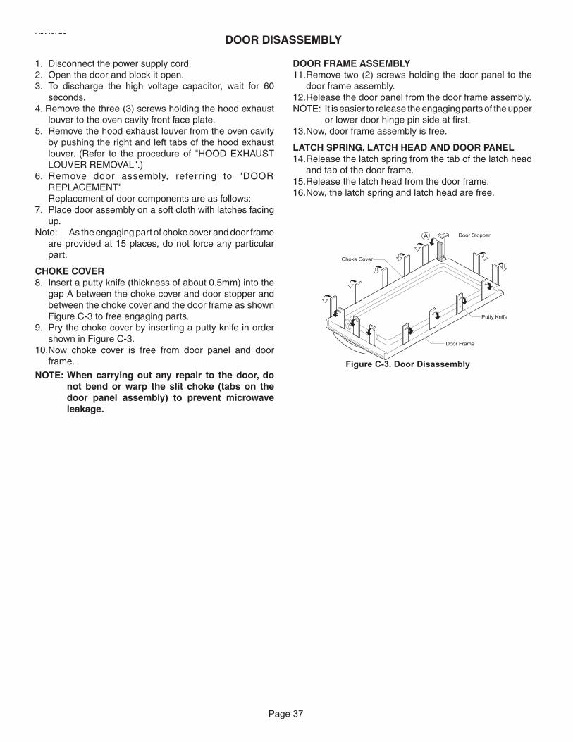
Page 3736
1. Disconnect the power supply cord.2. Open the door and block it open.3. To discharge the high voltage capacitor, wait for 60
seconds.4. Remove the three (3) screws holding the hood exhaust
louver to the oven cavity front face plate.5. Remove the hood exhaust louver from the oven cavity
by pushing the right and left tabs of the hood exhaust louver. (Refer to the procedure of "HOOD EXHAUSTLOUVER REMOVAL".)
6. Remove door assembly, referr ing to "DOORREPLACEMENT".Replacement of door components are as follows:
7. Place door assembly on a soft cloth with latches facing up.
Note: As the engaging part of choke cover and door frame are provided at 15 places, do not force any particular part.
CHOKE COVER8. Insert a putty knife (thickness of about 0.5mm) into the
gap A between the choke cover and door stopper and between the choke cover and the door frame as shown Figure C-3 to free engaging parts.
9. Pry the choke cover by inserting a putty knife in order shown in Figure C-3.
10.Now choke cover is free from door panel and door frame.
NOTE: When carrying out any repair to the door, do not bend or warp the slit choke (tabs on the door panel assembly) to prevent microwave leakage.
DOOR DISASSEMBLY
DOOR FRAME ASSEMBLY11.Remove two (2) screws holding the door panel to the
door frame assembly.12.Release the door panel from the door frame assembly.NOTE: It is easier to release the engaging parts of the upper
or lower door hinge pin side at first. 13.Now, door frame assembly is free.
LATCH SPRING, LATCH HEAD AND DOOR PANEL14.Release the latch spring from the tab of the latch head
and tab of the door frame.15.Release the latch head from the door frame.16.Now, the latch spring and latch head are free.
Figure C-3. Door Disassembly
A
Choke Cover
Door Frame
Door Stopper
Putty Knife
FMV157GSFMV157GBFMV157GMFMV157GQFMV157GC

Page 38
MAGNETRON
POWER RELAY(RELAY 2)
12
TTM
TURNTABLEMOTOR
120V
FM
FAN MOTOR
120VOVENLAMP
L
4
3
L
L
COOKTOP LAMP
6
MO
TOR
CAPACITO
R
9
HO
OD
THERM
AL C
UT-O
UT
(40/70)
8
1LAM
P RELAY
SUB RELAY(RELAY 1)
L.V.T
ON (RY3)
LOW (RY4)
T.P.VENTMOTOR
7HI (RY5)
VENT R
ELAY
MONITOR INTERLOOKSWITCH
9 WH
11 WH
12 WH
CO
NTR
OL P.W
.B. ASS'Y
4 BK3 BK
2 BK
1 BK
GN
GN
WH
BKFU
SE
FILTER ASS'Y
ON
LY
POW
ER SUPPLY :
SING
LE PHASE
PRIM
ARYIN
TERLO
CK ( UPPER)
(12 0/0 )
BOTTO
M TH
ERM
AL C
UT-O
UT
MG
T THER
MAL
CU
T-OU
T(1
6 0/95 )
CAVITY THERMAL CUT-OUT
(1 10/0)
DOORSENSESWITCH (BOTTOM)
27 OG
31 WH
32 YW
24 BK25 BL
26 GY
5 RD
30 WH
28 GN
29 YW
23 GN 21 YW
19 YW20 BL
6 YW
17 BK
16 WH
15 WH
18 OG
7 YW
8 BK
10 BK22 BR
H.V.DIODE
H.V.TRANS
FAF11
H.V.CAPACITOR
Schematic DiagramWarning : Power must be disconnected before servicing this appliance
MODEL NO. : FMV157GB, GS,GQ,GM,GC
NOTE: Door is open
BR:BROWNOG:ORANGE
WH:WHITE
GY:GREY
BK:BLACKRD:RED
YW:YELLOW
BL:BLUEGN:GREEN PK:PINK

Page 39
Wiring DiagramWarning : Power must be disconnected before servicing this applianceMODEL NO. : FMV157GB, GS,GQ,GM,GC
NOTE: For servicing replacement use 16GA,105 C thermoplastic covered wire
except for high voltage leads or as noted on special leads.
WH-11
1
12
RD-5
BR-22
OG-18
GN-23GY-26
BL-25
BK-24
WH-31
YW-32 BK-17
WH-15T/TABLEMOTOR
FANMOTORWH-16
WH-7
WH-15
OG-18
WH-16
BL-20
YW-6
BK-17OVENLAMP
GN-23
BL-20 YW-19
YW-21COOKTOPLAMP
WH-12
BK-10POWERRELAY
WH-30
GN-28YW-29
OG-27
BL-25
VENTMOTOR
CAVITYTHERMOSTATBK-2
BK-1
BK-2
BK-3MGTTHERMOSTAT
BOTTOMTHERMOSTATBK-4
BK-3
GY-26
BK-24HOODTHERMOSTATA
OG-27
WH-31
YW-32 DOORSENSINGSWITCH
YW-7
YW-6
PRIMARYSWITCH
BK
-4
WH
-9
MONITORSWITCH
WH
-11
BK
-8
YW-2
9
GN
-28
MOTORCONDENSER
BK
WH
BK
WH
GND
NOISEFILTER
BK
-1
WH
-12
OUT IN
BK
WH
POWERCORD
BK
-10
WH
-9B
K-8
H.V.TRANS
H.V.CAPACITOR
MGT TUBEFA
F
H.V.DIODE
WHRD
RD
RD
P C B
PK:PINKGN:GREENBL:BLUE
YW:YELLOWRD:RED BK:BLACK
GY:GREY
WH:WHITEOG:ORANGEBR:BROWN
GROUND
HARNESS LEADS
PARTS LEADS

Page 40
Publication No: 5995503355 FMV157G
11/07 2
OVEN,CABINET

Page 41
POS. NO1234 #5 #6 #7 #8 #9 #10 #11 #1213 #14 #15 #16 #17 #1819 #20 #21 #22 #2324252627 #28
DESCRIPTIONCover, waveguideCover, unit base, blackBase, transformer, right sideMagnetronThermostat, cutout, magnetronThermostat, cutout, oven cavityTransformer, power, HVCapacitor, HVDiode, HVFilter, noise, electronicFuseLampLampholder, socketPower Cord, electricThermostat, cutout, transformerThermostat, cutout, vent motorCapacitor, startLatch HookSwitch, leverSwitch, interlockSwitch, monitorWiring Harness, mainDuct, airFrame, lens holderLens, cooktop lamp, glassCover, lampFilter, greasePlate, mounting, rear
FMV157G
OVEN,CABINET
POS. NO 2930313233 #34 #3536373839 #40 #4142434445 #4647484950**
DESCRIPTIONGrille, exhaustCover, control shield, rightCover, lamp, oven cavityHardware Kit, installationFilter, charcoal, inside exhaustMotor, turntableCoupler, turntable/motorSupport, turntable ringTray, turntable, glassDuct, cooling fanFan Blade, cooling fanMotor, cooling fanDuct, hood intake, right sideVent, air outletDamper, doorFrame, damper housingMotor, hood/vent fanCover, vent motorRetainer, capacitor strapSpacerCabinet, outer casingMounting Nut KitScrew Kit, blackScrew Kit, white
#Functional Parts*Non Illustrated Parts
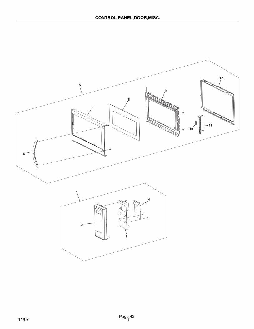
Page 42
Publication No: 5995503355 FMV157G
11/07 6
CONTROL PANEL,DOOR,MISC.
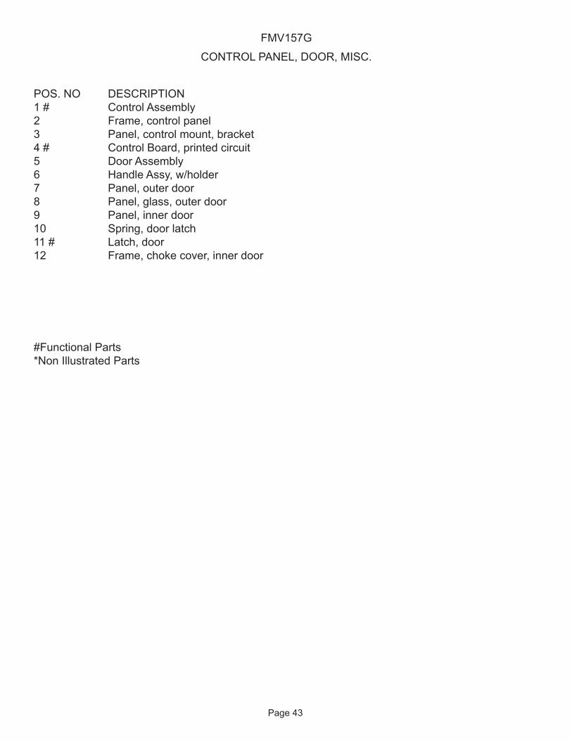
Page 43
POS. NO1 #234 #567891011 #12
DESCRIPTIONControl AssemblyFrame, control panelPanel, control mount, bracketControl Board, printed circuitDoor AssemblyHandle Assy, w/holderPanel, outer doorPanel, glass, outer doorPanel, inner doorSpring, door latchLatch, doorFrame, choke cover, inner door
FMV157G
CONTROL PANEL, DOOR, MISC.
#Functional Parts*Non Illustrated Parts

Page 44
64 51 2 3
64 51 2 3
A
B
C
D
E
F
G
H
A
B
C
D
E
F
G
H
31 TURNTABLE TRAY
TOP PAD
BOTTOM PAD
PACKING CASE
ACCESSORY PACK
WRAP COVER
DOOR PAD
Non-replaceable items
DOOR PROTECTOR
GREASE FILTER (x 2)77
INSTALL MATERIAL ASSEMBLY61
69 OPERATION MANUAL
70 TOP/WALL TEMPLATE
EXHAUST DAMPERASSEMBLY
78
50 INSTALLATION INSTRUCTIONS
PACKING AND ACCESSORIES
40
FMV157GSFMV157GBFMV157GMFMV157GQFMV157GC