Outline of Unified Process and Usecase-Driven … Ochimizu, JAIST UP outline 1 Schedule(3/3) •...
25
Koichiro Ochimizu, JAIST UP outline 1 Schedule(3/3) • March 18th – 13:00 Unified Process and Usecase-Driven Approach – 14:30 Case Study of Elevator Control System (problem definition, use case model) • March 19th – 13:00 Case Study of Elevator Control System (finding analysis classes by developing a consolidated communication diagram) – 14:30 Case Study of Elevator Control System (sub system structuring and task structuring) (sub-system structuring and task structuring) • March 24th – 13:00 Case Study of Elevator Control System ( performance analysis) – 14:30 UML2.0, Contribution of OO in SE Outline of Unified Process and Usecase-Driven Approach K i hi OCHIMIZU Koichiro OCHIMIZU School of Information Science JAIST
Transcript of Outline of Unified Process and Usecase-Driven … Ochimizu, JAIST UP outline 1 Schedule(3/3) •...

Koichiro Ochimizu, JAIST
UP outline 1
Schedule(3/3)• March 18th
– 13:00 Unified Process and Usecase-Driven Approach– 14:30 Case Study of Elevator Control Systemy y
(problem definition, use case model)• March 19th
– 13:00 Case Study of Elevator Control System(finding analysis classes by developing a consolidated communication diagram)
– 14:30 Case Study of Elevator Control System(sub system structuring and task structuring)(sub-system structuring and task structuring)
• March 24th– 13:00 Case Study of Elevator Control System
( performance analysis)– 14:30 UML2.0, Contribution of OO in SE
Outline of Unified Processand
Usecase-Driven Approach
K i hi OCHIMIZUKoichiro OCHIMIZU
School of Information Science
JAIST
Koichiro Ochimizu, JAIST
UP outline 2
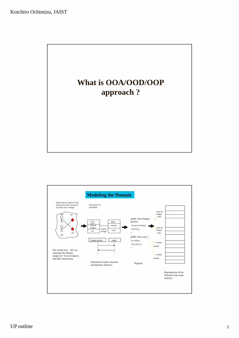
Wh t i OOA/OOD/OOPWhat is OOA/OOD/OOP approach ?
Abstraction of entities in the domain from the viewpoint of satisfy-one’s-hunger
h1 a1
h
Description of possibility
lpublic class hungry-
{
state-of-hunger
eat()
Modeling the Domain
The world view:We can represent the domain simply by “A set of objects
h2a2
hungrypersonstate of hunger
eat
apple
volume
eatensatisfy hunger
:hungry person :apple
person {
int state-of-hunger
void eat ()
}
public class apple {
int volume
void eaten ()
}
state-of-hungereat()
volume
eaten()
volume
and their interaction)Definition of static structure and dynamic behavior
Program
Reproduction of the Domain in the main memory
eaten()

Koichiro Ochimizu, JAIST
UP outline 3
How to incorporate three major merits of OOT into a system structure through OOSD
• Project the real world into the computer as you recognize and understand itrecognize and understand it.
• Maintain the virtual world constantly corresponding to mismatches between the real world and the virtual world and evolution of the real world.
RealWorld
VirtualWorld
Easy-to-change
Easy-to-reuse
Easy-to-evolve
Object Oriented Analysis/Design/Programming
Definition of Construction ofDomain ProgramModel
OOA OOD/OOP
Iterative and Incremental
Definition of the problem
Construction of the solution
Koichiro Ochimizu, JAIST
UP outline 4
What is SPM and SDM ?
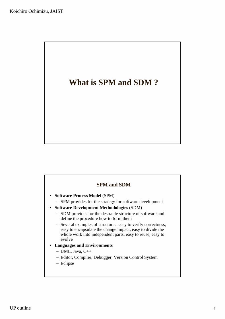
SPM and SDM
• Software Process Model (SPM)– SPM provides for the strategy for software development
• Software Development Methodologies (SDM)Software Development Methodologies (SDM)– SDM provides for the desirable structure of software and
define the procedure how to form them – Several examples of structures :easy to verify correctness,
easy to encapsulate the change impact, easy to divide the whole work into independent parts, easy to reuse, easy to evolve
• Languages and Environments– UML, Java, C++– Editor, Compiler, Debugger, Version Control System– Eclipse
Koichiro Ochimizu, JAIST
UP outline 5
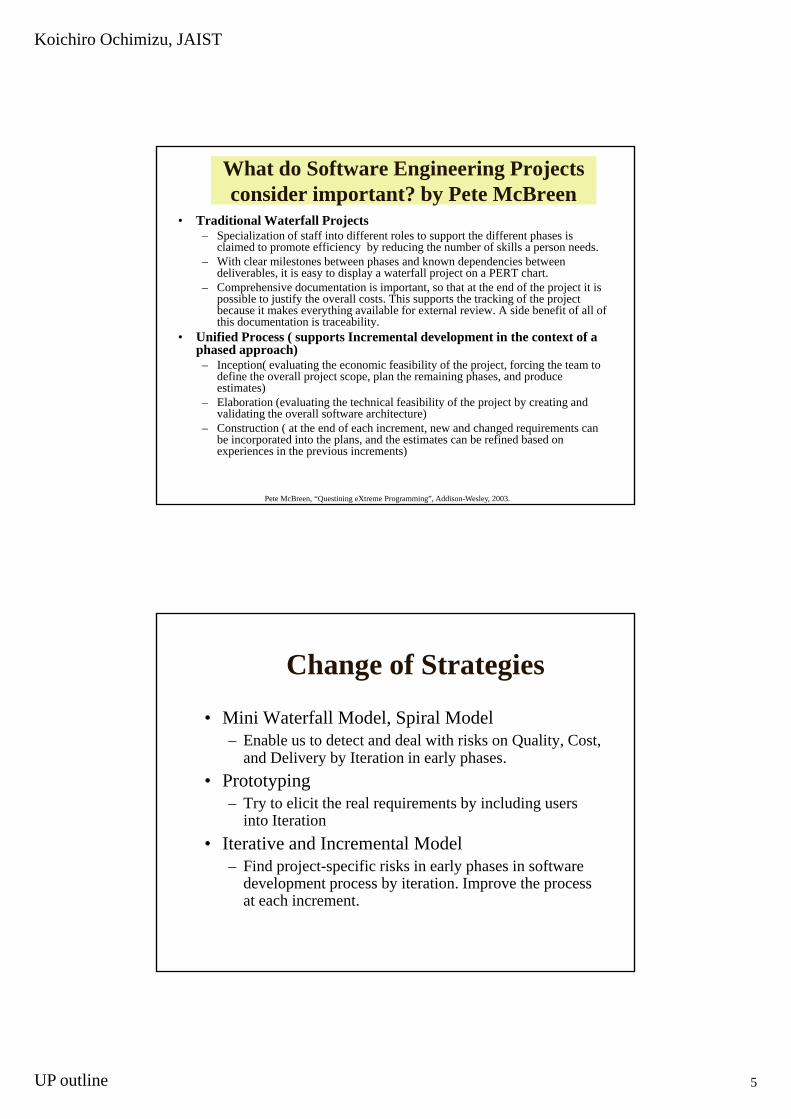
What do Software Engineering Projects consider important? by Pete McBreen
• Traditional Waterfall Projects– Specialization of staff into different roles to support the different phases is
claimed to promote efficiency by reducing the number of skills a person needs.– With clear milestones between phases and known dependencies between p p
deliverables, it is easy to display a waterfall project on a PERT chart.– Comprehensive documentation is important, so that at the end of the project it is
possible to justify the overall costs. This supports the tracking of the project because it makes everything available for external review. A side benefit of all of this documentation is traceability.
• Unified Process ( supports Incremental development in the context of a phased approach)
– Inception( evaluating the economic feasibility of the project, forcing the team to define the overall project scope, plan the remaining phases, and produce
ti t )estimates)– Elaboration (evaluating the technical feasibility of the project by creating and
validating the overall software architecture)– Construction ( at the end of each increment, new and changed requirements can
be incorporated into the plans, and the estimates can be refined based on experiences in the previous increments)
Pete McBreen, “Questining eXtreme Programming”, Addison-Wesley, 2003.
Change of Strategies
• Mini Waterfall Model, Spiral Model– Enable us to detect and deal with risks on Quality, Cost,
and Delivery by Iteration in early phases.• Prototyping
– Try to elicit the real requirements by including users into Iteration
• Iterative and Incremental Model– Find project-specific risks in early phases in software
development process by iteration. Improve the process at each increment.

Koichiro Ochimizu, JAIST
UP outline 6
What is the Unified Process ?
Activities are overlapping !(Relative levels of effort expected across the phases)
Inception Elaboration Construction Transition(Idea) (Architecture) (Beta-Releases) (Products)
Management
Environment
Requirements
Design
Walker Royce, “Software Project Management A Unified Framework”, ADDISON-WESLY, 1998.
Implementation
Assessment
Deployment
Koichiro Ochimizu, JAIST
UP outline 7
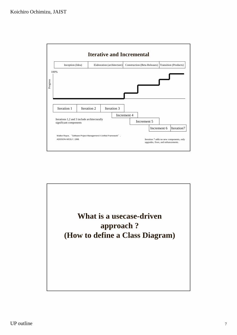
Iterative and Incremental
Inception (Idea) Elaboration (architecture) Construction (Beta Releases) Transition (Products)
100%
sPr
ogre
ss
Iteration 1 Iteration 2 Iteration 3
Increment 4Increment 4
Increment 5
Increment 6 Iteration7
Iterations 1,2 and 3 include architecturally significant components
Iteration 7 adds no new components, only upgrades, fixes, and enhancements.
Walker Royce, “Software Project Management A Unified Framework”,
ADDISON-WESLY, 1998.
What is a usecase-driven approach ?
(How to define a Class Diagram)
Koichiro Ochimizu, JAIST
UP outline 8
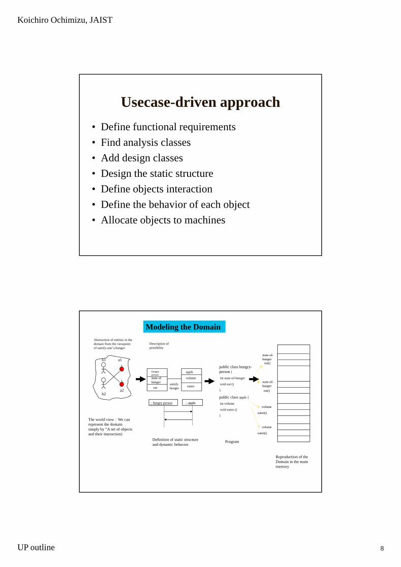
Usecase-driven approach• Define functional requirements• Find analysis classes• Add design classes • Design the static structure• Define objects interaction• Define the behavior of each object• Allocate objects to machines
Abstraction of entities in the domain from the viewpoint of satisfy-one’s-hunger
h1 a1
h
Description of possibility
lpublic class hungry-
{
state-of-hunger
eat()
Modeling the Domain
The world view:We can represent the domain simply by “A set of objects
h2a2
hungrypersonstate of hunger
eat
apple
volume
eatensatisfy hunger
:hungry person :apple
person {
int state-of-hunger
void eat ()
}
public class apple {
int volume
void eaten ()
}
state-of-hungereat()
volume
eaten()
volume
and their interaction)Definition of static structure and dynamic behavior
Program
Reproduction of the Domain in the main memory
eaten()
Koichiro Ochimizu, JAIST
UP outline 9
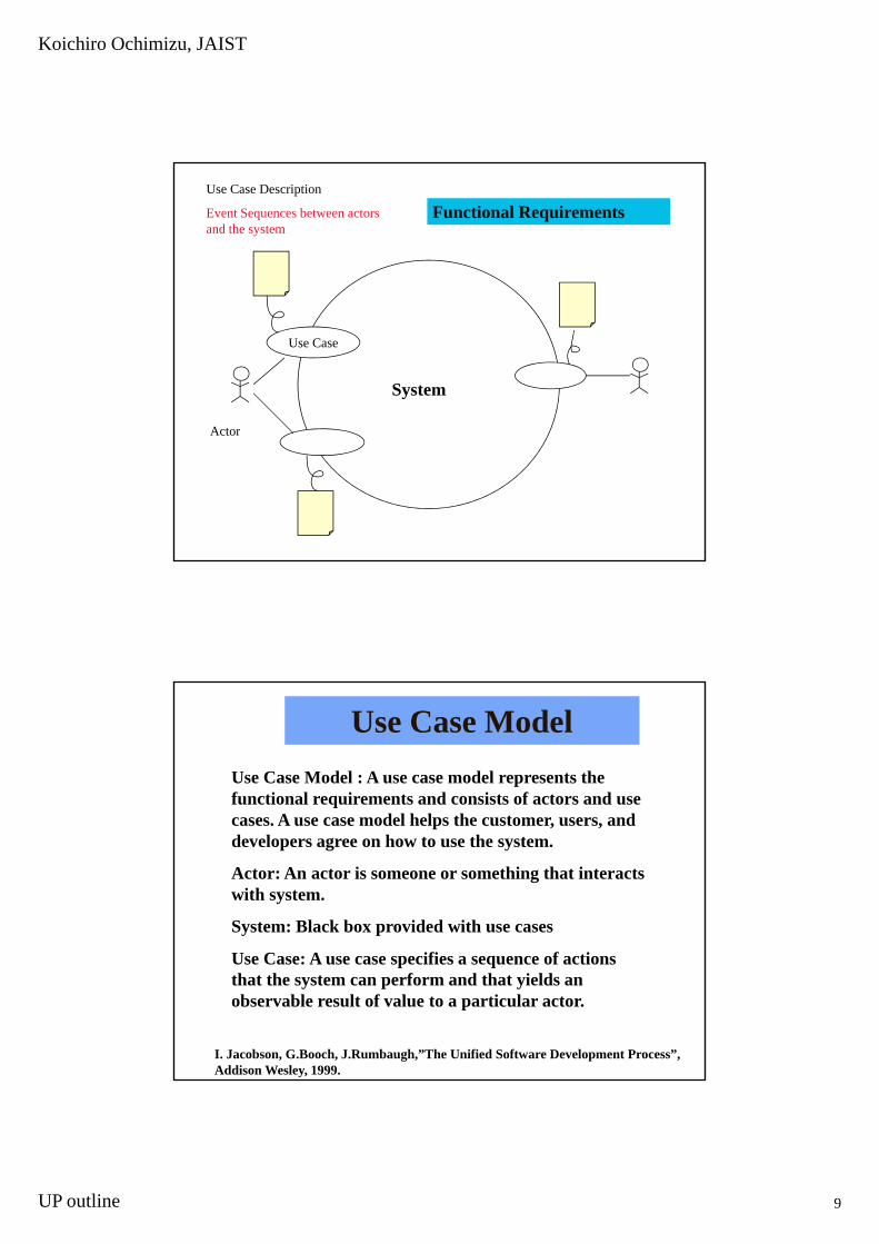
Use Case Description
Event Sequences between actors and the system
Functional Requirements
Use Case
System
A tActor
Use Case ModelUse Case Model : A use case model represents the functional requirements and consists of actors and use
A d l h l h dcases. A use case model helps the customer, users, and developers agree on how to use the system.
Actor: An actor is someone or something that interacts with system.
System: Black box provided with use cases
Use Case: A use case specifies a sequence of actionsthat the system can perform and that yields an observable result of value to a particular actor.
I. Jacobson, G.Booch, J.Rumbaugh,”The Unified Software Development Process”, Addison Wesley, 1999.
Koichiro Ochimizu, JAIST
UP outline 10
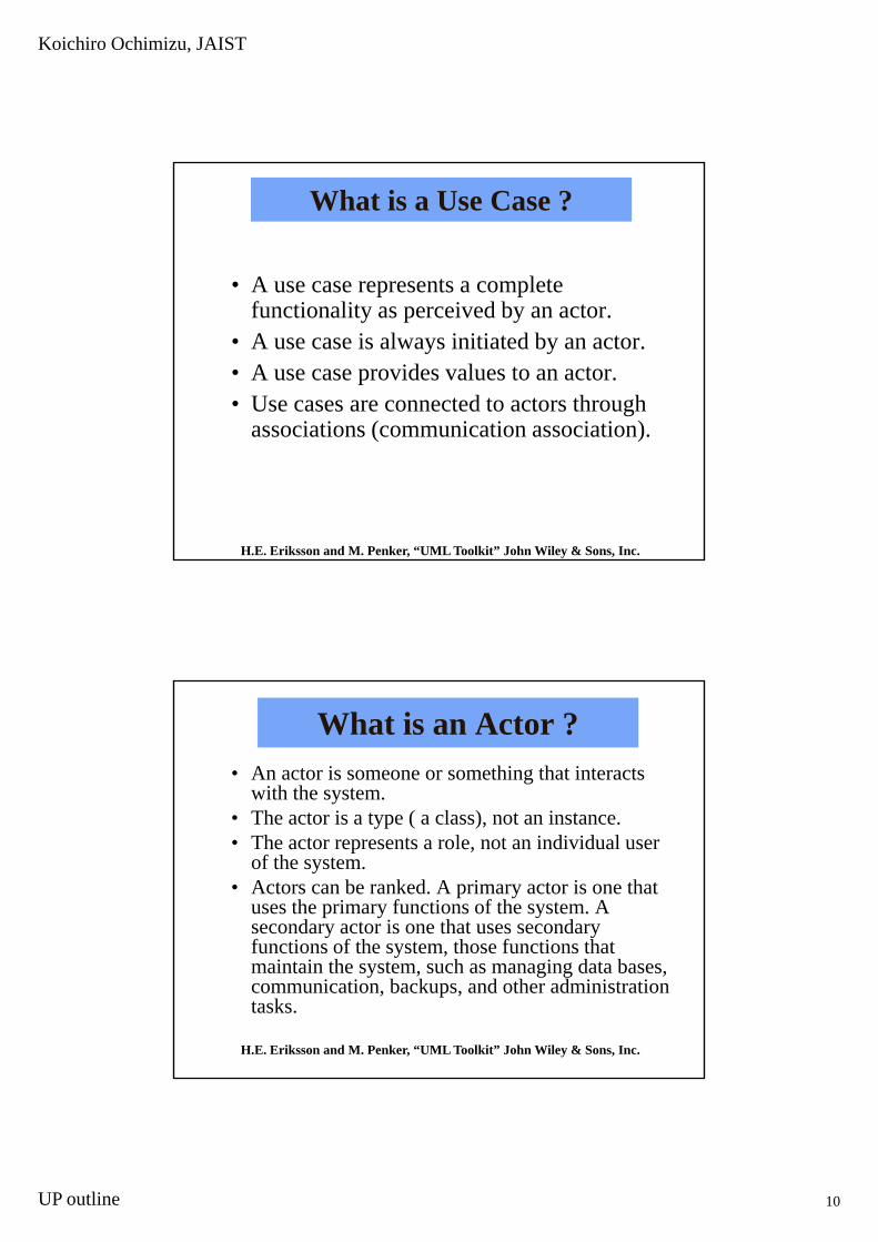
What is a Use Case ?
• A use case represents a complete p pfunctionality as perceived by an actor.
• A use case is always initiated by an actor.• A use case provides values to an actor.• Use cases are connected to actors through
associations (communication association)associations (communication association).
H.E. Eriksson and M. Penker, “UML Toolkit” John Wiley & Sons, Inc.
What is an Actor ?• An actor is someone or something that interacts
with the system.Th t i t ( l ) t i t• The actor is a type ( a class), not an instance.
• The actor represents a role, not an individual user of the system.
• Actors can be ranked. A primary actor is one that uses the primary functions of the system. A secondary actor is one that uses secondary functions of the system those functions thatfunctions of the system, those functions that maintain the system, such as managing data bases, communication, backups, and other administration tasks.
H.E. Eriksson and M. Penker, “UML Toolkit” John Wiley & Sons, Inc.
Koichiro Ochimizu, JAIST
UP outline 11
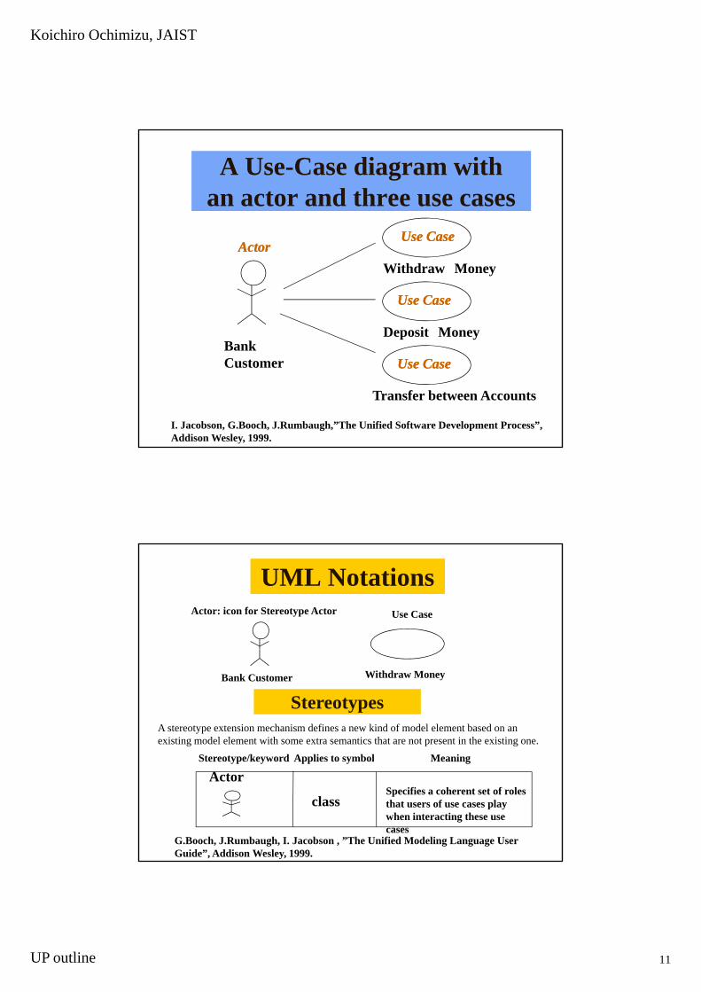
A Use-Case diagram withan actor and three use cases
Use CaseUse Case
B kDeposit Money
Withdraw MoneyActorActor
Use CaseUse Case
Use CaseUse Case
Bank Customer
Transfer between Accounts
I. Jacobson, G.Booch, J.Rumbaugh,”The Unified Software Development Process”, Addison Wesley, 1999.
Use CaseUse Case
UML NotationsActor: icon for Stereotype Actor Use Case
Bank Customer Withdraw Money
Stereotypes
St t /k d A li t b l M i
A stereotype extension mechanism defines a new kind of model element based on an existing model element with some extra semantics that are not present in the existing one.
G.Booch, J.Rumbaugh, I. Jacobson , ”The Unified Modeling Language User Guide”, Addison Wesley, 1999.
Stereotype/keyword Applies to symbol Meaning
classSpecifies a coherent set of roles that users of use cases play when interacting these use cases
Actor

Koichiro Ochimizu, JAIST
UP outline 12
Use Case Description
Event Sequences between actors and the system
Analysis of inside of the system
Use Case
A t
Collaboration
Collaboration
ActorCollaboration
UML notation
C iCollaborationcollaboration name
A collaboration gives a name to the mechanism of the system
It also serve as the realization of a use case
It defines a group of objects and their
<<trace>>
interaction
A directed dashed line means dependency
In this case, trace dependency
G.Booch, J.Rumbaugh, I. Jacobson , ”The Unified Modeling Language User Guide”, Addison Wesley, 1999.
Koichiro Ochimizu, JAIST
UP outline 13
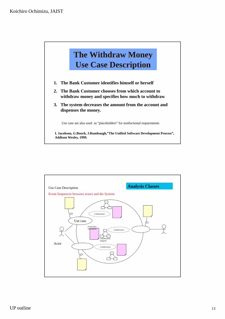
The Withdraw Money Use Case Description
1. The Bank Customer identifies himself or herself
2. The Bank Customer chooses from which account to withdraw money and specifies how much to withdraw
3. The system decreases the amount from the account and dispenses the moneydispenses the money.
Use case are also used as “placeholders” for nonfuctional requirements
I. Jacobson, G.Booch, J.Rumbaugh,”The Unified Software Development Process”, Addison Wesley, 1999.
Use Case Description
Event Sequences between actors and the System
Analysis Classes
Use case
A t
Collaboration
Collaboration
Collaboration Diagram
Event Flow Description
ActorCollaboration

Koichiro Ochimizu, JAIST
UP outline 14
• Focus on functional requirements in defining analysis class. D l i h f i l i i d i h
Analysis Class
Deal with non functional requirements in design phase or implementation phase.
• Make the class responsibility clear• Define attributes that exist in a real world• Define association but do not Include details like
navigationg• Use stereotype classes; <<boundary>>, <<control>>, and
<<entity>>.
Analysis Stereotypes• <<boundary>> classes in general are used to
model interaction between the system and its actors.
• <<entity>> classes in general are used to model information that is long-lived and often persistent.
• <<control>> classes are generally used to represent coordination sequencing transactionsrepresent coordination, sequencing, transactions, and control of other objects. And it is often used to encapsulate control related to a specific use case.
I. Jacobson, G.Booch, J.Rumbaugh,”The Unified Software Development Process”, Addison Wesley, 1999.

Koichiro Ochimizu, JAIST
UP outline 15
Analysis StereotypesIn the analysis model, three different stereotypes on classes are used: <<boundary>> <<control>> <<entity>>
Dispenser Cashier InterfaceBoundary
Withd lControl
classes are used: <<boundary>>, <<control>>, <<entity>>.
AccountEntity
Withdrawal
I. Jacobson, G.Booch, J.Rumbaugh,”The Unified Software Development Process”, Addison Wesley, 1999.
The Realization of a Use Case in the Analysis Model
<<trace>>UseUse--Case ModelCase Model Analysis ModelAnalysis Model
Withdraw Money Withdraw Money
<<trace>>CollaborationCollaborationUse CaseUse Case
Dispenser CashierInterface
Withdrawal Account
I. Jacobson, G.Booch, J.Rumbaugh,”The Unified Software Development Process”, Addison Wesley, 1999.
Koichiro Ochimizu, JAIST
UP outline 16
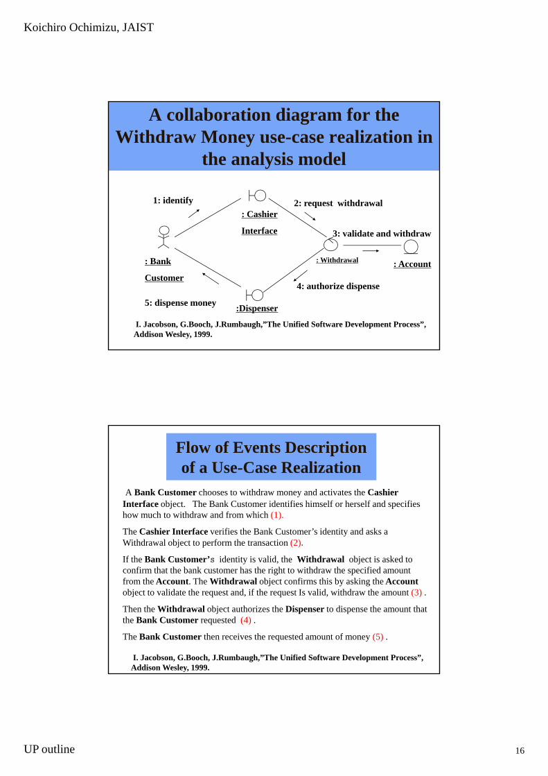
A collaboration diagram for the Withdraw Money use-case realization in
the analysis model
: Account
: Cashier
Interface
: Withdrawal
3: validate and withdraw
2: request withdrawal
: Bank
1: identify
:Dispenser
4: authorize dispense
5: dispense money
Customer
I. Jacobson, G.Booch, J.Rumbaugh,”The Unified Software Development Process”, Addison Wesley, 1999.
Flow of Events Description of a Use-Case Realization
A Bank Customer chooses to withdraw money and activates the Cashier Interface object. The Bank Customer identifies himself or herself and specifies j phow much to withdraw and from which (1).
The Cashier Interface verifies the Bank Customer’s identity and asks a Withdrawal object to perform the transaction (2).
If the Bank Customer’s identity is valid, the Withdrawal object is asked to confirm that the bank customer has the right to withdraw the specified amount from the Account. The Withdrawal object confirms this by asking the Account
bj t t lid t th t d if th t I lid ithd th t (3)object to validate the request and, if the request Is valid, withdraw the amount (3) .
Then the Withdrawal object authorizes the Dispenser to dispense the amount that the Bank Customer requested (4) .
The Bank Customer then receives the requested amount of money (5) .
I. Jacobson, G.Booch, J.Rumbaugh,”The Unified Software Development Process”, Addison Wesley, 1999.
Koichiro Ochimizu, JAIST
UP outline 17
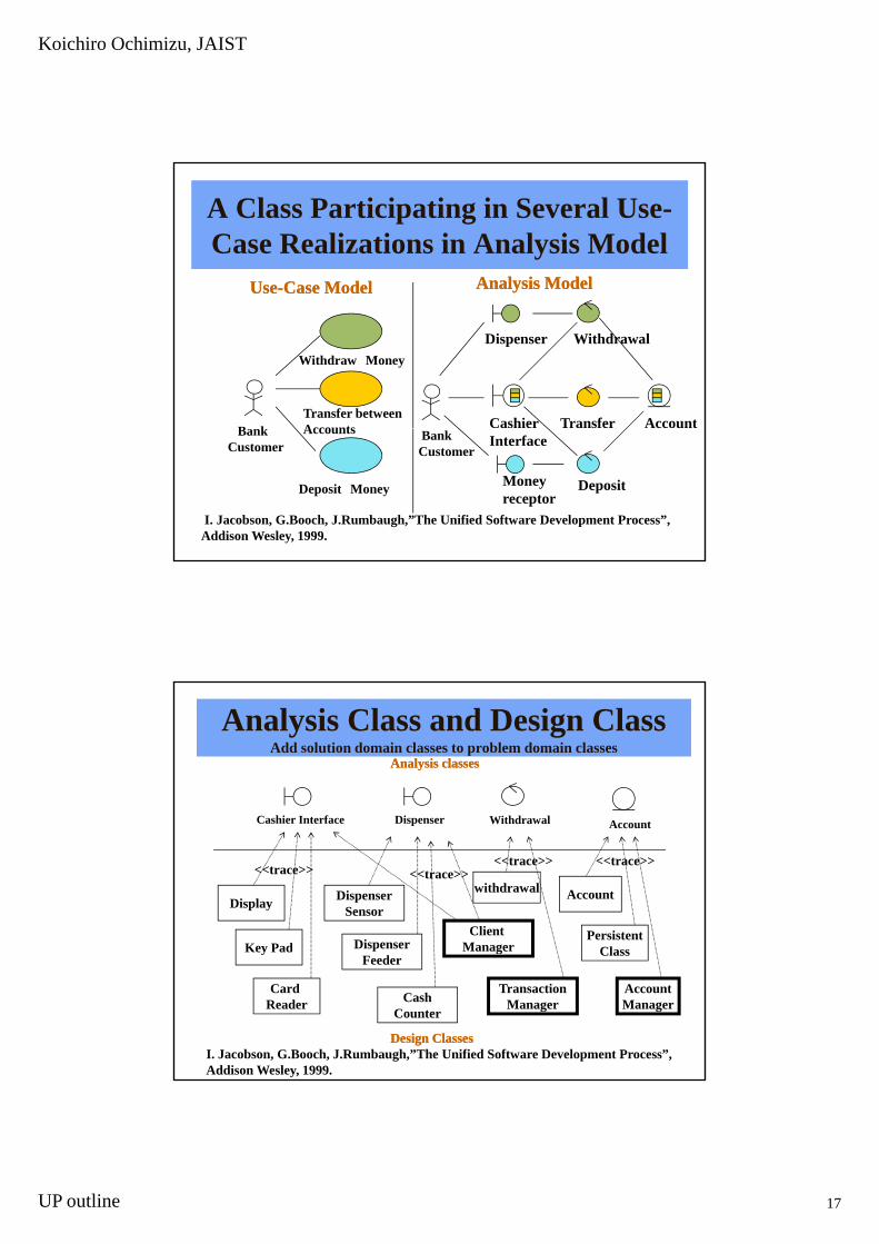
A Class Participating in Several Use-Case Realizations in Analysis Model
UseUse--Case ModelCase Model Analysis ModelAnalysis Model
B k
Withdraw Money
Transfer between Accounts
Dispenser
Cashier Account
Withdrawal
Transfer
I. Jacobson, G.Booch, J.Rumbaugh,”The Unified Software Development Process”, Addison Wesley, 1999.
Bank Customer
Deposit Money
Accounts Bank Customer
Interface
Money receptor
Deposit
Analysis Class and Design ClassAdd solution domain classes to problem domain classes
Analysis classesAnalysis classes
AccountCashier Interface Dispenser Withdrawal
DispenserSensor
Dispenser
<<trace>>
Display
Key Pad
withdrawal<<trace>>
PersistentCl
Account
<<trace>> <<trace>>
Client Manager
Card Reader Cash
Counter
DispenserFeeder
Key Pad
TransactionManager
AccountManager
Class
Design ClassesDesign Classes
Manager
I. Jacobson, G.Booch, J.Rumbaugh,”The Unified Software Development Process”, Addison Wesley, 1999.

Koichiro Ochimizu, JAIST
UP outline 18
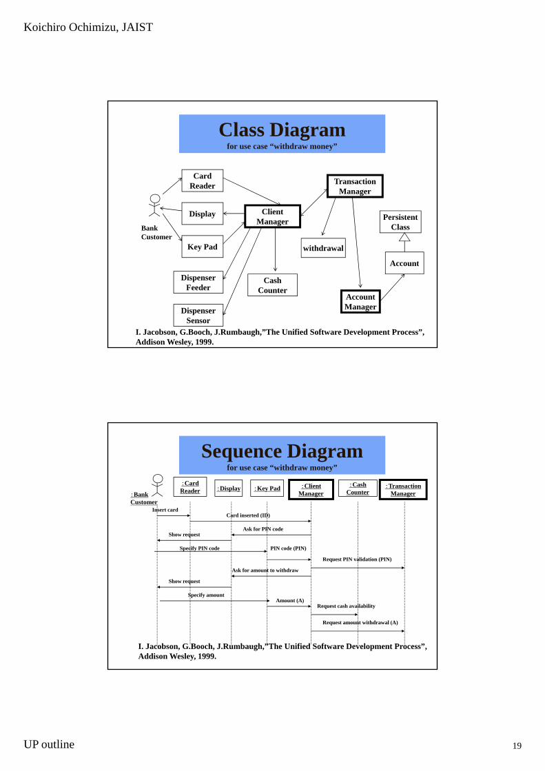
Class Diagram (Analysis Class + Design Class)
Use Case
A tActor
Final Step of Modeling (Definition of Static Structure and Dynamic Behavior)
Use case
A tActor
Koichiro Ochimizu, JAIST
UP outline 19
CardR d Transaction
Class Diagramfor use case “withdraw money”
Reader
Display
Key Pad withdrawal
ClientManager
TransactionManager
PersistentClass
Account
Bank Customer
DispenserSensor
CashCounter
DispenserFeeder
AccountManager
Account
I. Jacobson, G.Booch, J.Rumbaugh,”The Unified Software Development Process”, Addison Wesley, 1999.
:CardReader
:CashCounter:Display :Key Pad :Client
Manager:Transaction
Manager
Sequence Diagramfor use case “withdraw money”
:Bank Customer
Insert cardCard inserted (ID)
Ask for PIN code
PIN code (PIN)
Ask for amount to withdraw
Show request
Show request
Specify PIN code
Request PIN validation (PIN)
Specify amountAmount (A)
Request cash availability
Request amount withdrawal (A)
I. Jacobson, G.Booch, J.Rumbaugh,”The Unified Software Development Process”, Addison Wesley, 1999.

Koichiro Ochimizu, JAIST
UP outline 20
Communication Association between nodes
ClientA:Compaq Pro PC
ApplicationServer:
Silicon GraphicsO2
DatabaseServer:VAX
“TCP/IP” <<DecNet>>
ClientB:Compaq Pro PC “TCP/IP”
H.E. Eriksson and M. Penker, “UML Toolkit” John Wiley & Sons, Inc.
UML notation
NodeA physical element that exists at run time and that represents a computational resource, generally having at least some memory and, often times, processing capability
ATMData
Server
processing capability
G.Booch, J.Rumbaugh, I. Jacobson , ”The Unified Modeling Language User Guide”, Addison Wesley, 1999.
Koichiro Ochimizu, JAIST
UP outline 21
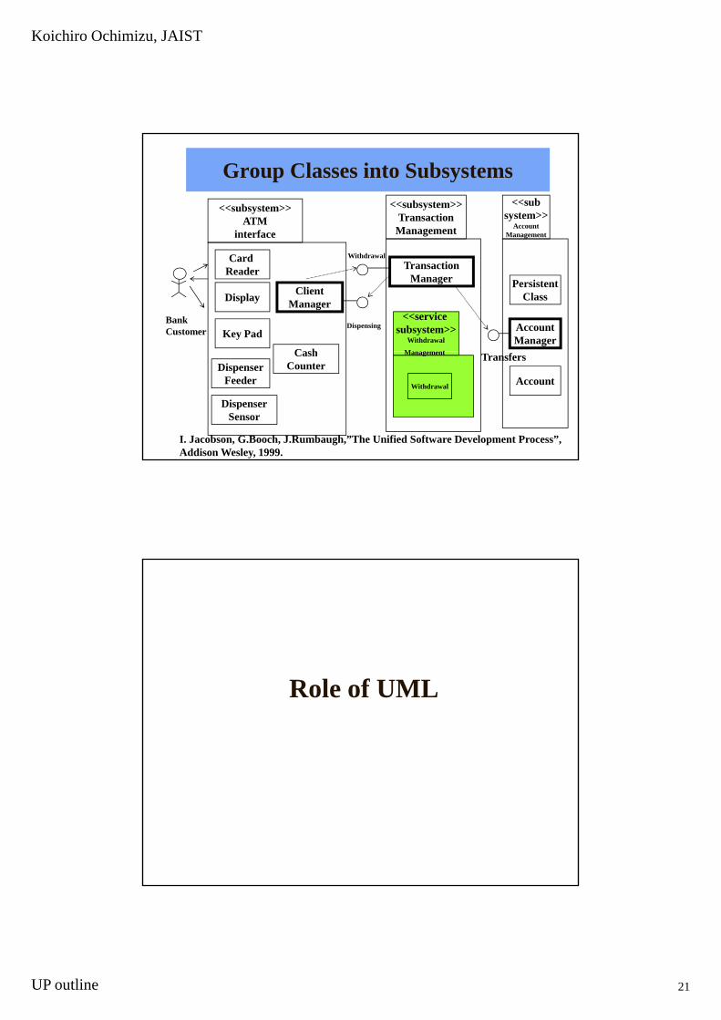
Group Classes into Subsystems<<subsystem>>
ATMinterface
<<subsystem>>Transaction
Management
<<subsystem>>
AccountManagement
AccountManager
PersistentClass
Card Reader
Cash
Display
Key Pad
ClientManager
TransactionManager
<<service subsystem>>
Withdrawal
Management
Withdrawal
DispensingBank Customer
Account
DispenserSensor
CashCounterDispenser
FeederWithdrawal
Management Transfers
I. Jacobson, G.Booch, J.Rumbaugh,”The Unified Software Development Process”, Addison Wesley, 1999.
Role of UML

Koichiro Ochimizu, JAIST
UP outline 22
Relationship between
Methods and UML
Method 1 Method 2 Method 3
Description
UML
The Views in UML
Use-CaseView
LogicalView
ComponentView
ConcurrencyView
DeploymentView
H.E. Eriksson and M. Penker, “UML Toolkit” John Wiley & Sons, Inc.
Koichiro Ochimizu, JAIST
UP outline 23
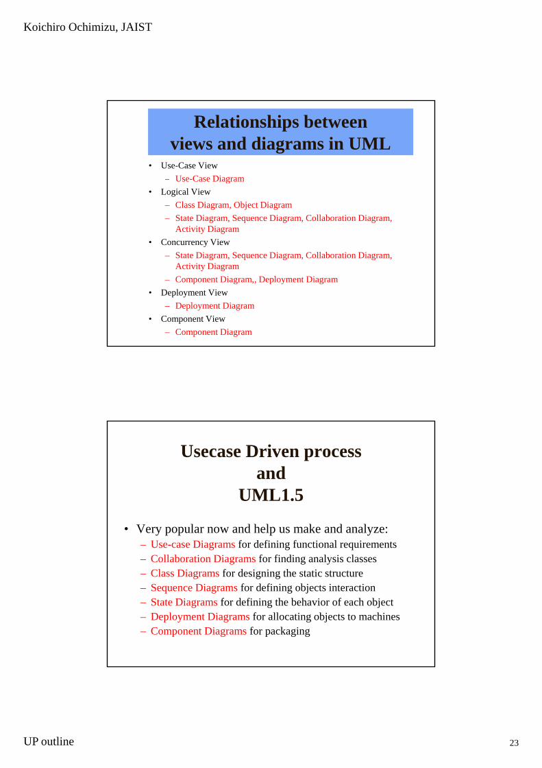
Relationships between views and diagrams in UML
• Use-Case View– Use-Case Diagramg
• Logical View– Class Diagram, Object Diagram– State Diagram, Sequence Diagram, Collaboration Diagram,
Activity Diagram• Concurrency View
– State Diagram, Sequence Diagram, Collaboration Diagram, A ti it DiActivity Diagram
– Component Diagram,, Deployment Diagram• Deployment View
– Deployment Diagram• Component View
– Component Diagram
Usecase Driven processand
UML1.5
• Very popular now and help us make and analyze:– Use-case Diagrams for defining functional requirements– Collaboration Diagrams for finding analysis classes – Class Diagrams for designing the static structure
S Di f d fi i bj t i t ti– Sequence Diagrams for defining objects interaction– State Diagrams for defining the behavior of each object– Deployment Diagrams for allocating objects to machines– Component Diagrams for packaging

Koichiro Ochimizu, JAIST
UP outline 24
The Unified SoftwareDevelopment Process
• Use-Case ModelU C Di– Use-Case Diagram
• Analysis Model– describe “Realization of a Use-Case” by a Collaboration
Diagram and a Flow of Event Description• Design Model
– Class Diagram , Sequence Diagram, and Statechart Diagram• Deployment Modelp y
– Deployment Diagram• Implementation Model
– Component Diagram• Test Model
– Test Case
UML2.0 Views• Major Area,
– View• Diagram
– Main Concepts• structural
– static view:class diagram– design view:internal structure (connector, interface, part, port, provided
interface, role, required interface), collaboration diagram (connector, collaboration use, role), component diagram (component, dependency, port, provided interface, realization, required interface, subsystem)
– use case view:usecase diagram• dynamic
– state machine view:state machine diagram– activity view:activity diagram– interaction view:sequence diagram, communication diagram
• physical– deployment view:deployment diagram
• model management– model management view:package diagram– profile:package diagram
Koichiro Ochimizu, JAIST
UP outline 25
Exercise• Review the content of my lecture by answering the following
simple questions. Please describe the definition of each technical p qterm.
1. Please describe the relationship between UML and methods.2. Why do we define the use case model?3. What is a use case description ?4. What is an collaboration of UML?5. What are analysis ( or problem domain ) classes?6. What are design classes?7 How can we define the interaction among objects using UML7. How can we define the interaction among objects using UML
notations?8. How can we define the behavior (or lifecycle) of an object using
UML notations?9. What is a stereotype of UML?