Outdoor Wall Hung Oil Boiler Range Installation...
44
Grant Condensing Outdoor Wall Hung Oil Boiler Range Installation & Servicing Instructions Part No. DOC 85. Rev 00. May 2009
Transcript of Outdoor Wall Hung Oil Boiler Range Installation...
Grant CondensingOutdoor Wall Hung Oil Boiler Range
Installation & Servicing Instructions
Part No. DOC 85. Rev 00. May 2009
Commissioning Report
2
Co
mm
issi
oni
ngR
epo
rt
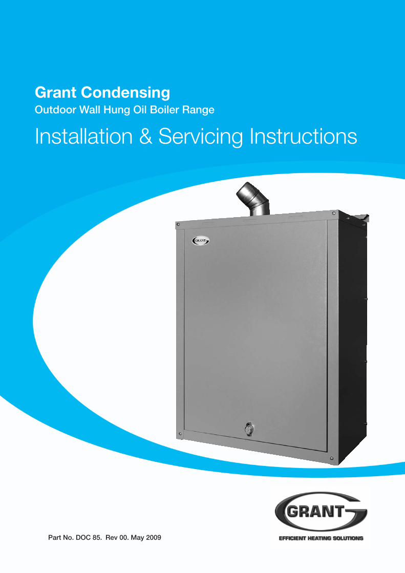
For use with Kerosene only.
After installing the boiler leave theseinstructions with the User.
This appliance is deemed a controlledservice and specific regional statutoryrequirements may be applicable.
Date:
Commissioning engineer: Tel. No:
Boiler model/output: kW
Fuel type: Kerosene
Nozzle size: Pump pressure:
Air setting: Flue gas % CO2:
Net flue gas temp: Smoke No:
GRANT ENGINEERING (IRELAND) LIMITEDCrinkle, Birr, Co. Offaly, IrelandTel: (057) 91 20089 Fax: (057) 91 21060Email: [email protected] www.grantengineering.ie
This manual is accurate at the date of printing but will be superseded and should be disregarded if specifications and/orappearances are changed in the interests of continued product improvement.All good sold are subject to our official Conditions of Sale, a copy of which may be obtained on application.© Grant Engineering (Ireland) Limited 2008. No part of this manual may be reproduced by any means without prior writtenconsent.
Contents
Co
nten
ts
3
1 Introduction 41.1 How a condensing boiler works 4
1.2 Boiler Description 4
1.3 Boiler Components 5
2 Technical Data 62.1 Boiler technical data –
Condensing Outdoor wall-hung boilers 6
2.2 Condensing boilers using Class C2 kerosene 7
2.3 Flue gas analysis 7
2.4 Outdoor boiler panel assembly 8
3 Oil Storage & Supply System 93.1 Fuel supply 9
3.2 Burner oil connection 11
4 Boiler Installation Information 134.1 Introduction 13
4.2 Boiler location 13
4.3 Preparation for installation 13
4.4 Dismantling the boiler 13
4.5 Installing the boiler 15
4.6 Regulations compliance 16
4.7 Completion 17
4.8 Before you commission 17
4.9 Heating system design considerations 17
4.10 Underfloor heating systems 17
4.11 Pipework materials 17
4.12 Underfloor pipework 17
5 Pipe Connections 185.1 Water connections 18
6 Condensate Disposal 196.1 General requirements 19
6.2 Connections 19
6.3 Pipework 19
6.4 External pipework 19
6.5 Condensate soakaway 19
6.6 Condensate trap 20
6.7 Condensate disposal pipework 20
6.8 Inspection and cleaning of trap 20
7 Electrical 217.1 Connecting the power supply 21
7.2 Frost protection 21
7.3 Control system wiring diagrams 21
7.4 Boiler control panel wiring diagrams 22
8 Flue System & Air Supply 238.1 Air supply 23
8.2 Conventional flue systems 23
8.3 External conventional flue 23
9 Commissioning 269.1 Before switching on 26
9.2 Switching on 26
9.3 Running the boiler 27
9.4 Balancing the system 27
9.5 Completion 27
10 Boiler Servicing 2810.1 Checking before servicing 28
10.2 Dismantling prior to servicing 28
10.3 Cleaning the boiler 28
10.4 Cleaning the burner 29
11 Fault Finding 3011.1 Burner fault finding 30
11.2 Boiler fault finding 33
12 Spare Parts 34
13 Health & Safety Information 3613.1 Insulation materials 36
13.2 Kerosene and gas oil fuels (mineral oils) 36
14 EC Declaration of Conformity 37
1 Introduction
4
Intr
od
ucti
on
This manual is intended to guideengineers in the installation andmaintenance of Grant CONDENSINGOutdoor Wall Hung boilers. A UserGuide for the operation of this boiler isattached to the reverse of this manual.
The following special text formats areused in this manual for the purposeslisted below:
Warning of possible human injury asa consequence of not following theinstructions in the warning.
1.1 How a CondensingBoiler WorksDuring the combustion process,hydrogen and oxygen combine toproduce heat and water vapour. Thewater vapour produced is in the form ofsuperheated steam in the heatexchanger. This superheated steamcontains sensible heat (available heat)and latent heat (heat locked up in theflue gas). A conventional boiler cannotrecover any of the latent heat and thisenergy is lost to the atmospherethrough the flue.
The Grant CONDENSING Outdoor WallHung condensing boiler contains anextra heat exchanger which is designedto recover the latent heat normally lostby a conventional boiler. It does this bycooling the flue gases to below 90°C,thus extracting more sensible heat andsome of the latent heat. This is achievedby cooling the flue gases to their dewpoint (approximately 55°C).
To ensure maximum efficiency, the boilerreturn temperature should be 55°C orless, this will enable the latent heat to becondensed out of the flue gases.
The boiler will achieve net thermalefficiencies of 100%.
To achieve maximum performance fromthe Grant CONDENSING Outdoor WallHung boiler, it is recommended that theheating system is designed so that atemperature differential of 20°C betweenthe flow and return is maintained. Theuse of modulating circulating pumps(now widely available) and effectivecontrol systems should be considered.
The Grant Condensing boiler willhowever still operate at extremely highefficiencies even when it is not incondensing mode and therefore issuitable for fitting to an existing heatingsystem without alteration to the radiatorsizes. The boiler is capable of amaximum flow temperature of 75°C.
1.2 Boiler DescriptionThe Condensing Outdoor Modules havean insulated weatherproof enclosuremade of galvanised steel with a powdercoated finish, and are designed forexternal installation, Mounted on asuitable external wall.
The Grant CONDENSING Outdoormodules are part of the Grant range ofautomatic pressure jet oil boilers, andhave been designed for use with a fullypumped central heating system withindirect domestic hot water cylinder.They are not suitable for use with eithera direct cylinder or a 'primatic' cylinderor gravity hot water.
The boilers are suitable for use on openvented or sealed central heatingsystems. All models are supplied withthe control panel and burner factoryfitted.
The boilers are supplied with a flueterminal, but can be connected to aconventional flue system.
An external conventional flue (Green)system is available from. Refer toChapter 9 for further details includingthe list of available components of thissystem.
Caution concerning likely damage toequipment or tools as aconsequence of not following theinstructions in the caution.
The flue system materials andconstruction must be suitable foruse with oil-fired condensing boilers.Failure to fit a suitable conventionalflue may invalidate the warranty onthe boiler.
Note text. Used for emphasis orinformation not directly concernedwith the surrounding text but ofimportance to the reader.
! WARNING
! CAUTION
! NOTE
! NOTE
Intr
od
ucti
on
5
1.3 Boiler ComponentsAll burners are pre-set for use withkerosene and are supplied ready toconnect to a two pipe fuel supplysystem with two flexible fuel lines and3/8" to 1/4" BSP male adaptor suppliedwith the boiler.
The temperature of the water leavingthe boiler to heat the radiators and hotwater cylinder is User adjustable.
The boiler is fitted with an overheatthermostat (which allows it to be usedon a sealed central heating system)which will automatically switch off theboiler if the heat exchanger exceeds apre-set temperature of 111°C ± 3°C.
The control panel is fitted with anON/OFF switch, boiler thermostatcontrol knob and the manual resetbutton for the overheat thermostat.
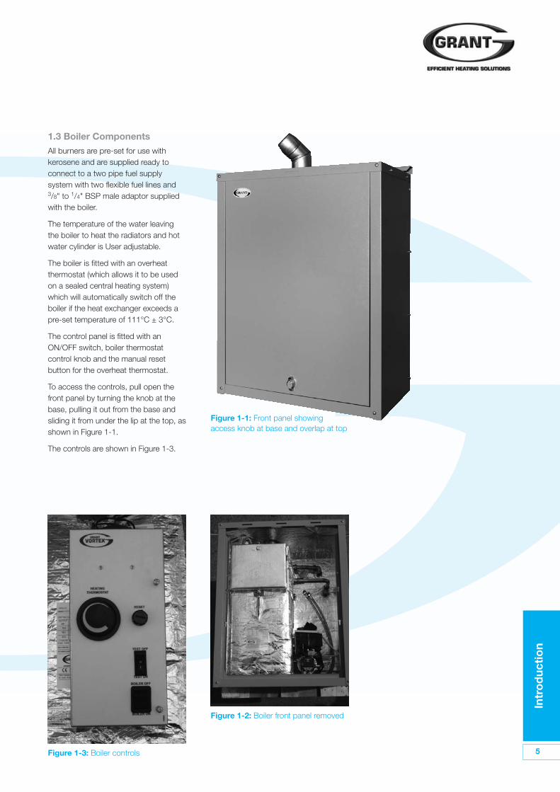
To access the controls, pull open thefront panel by turning the knob at thebase, pulling it out from the base andsliding it from under the lip at the top, asshown in Figure 1-1.
The controls are shown in Figure 1-3.
Figure 1-3: Boiler controls
Figure 1-2: Boiler front panel removed
Figure 1-1: Front panel showingaccess knob at base and overlap at top
2 Technical Data
6
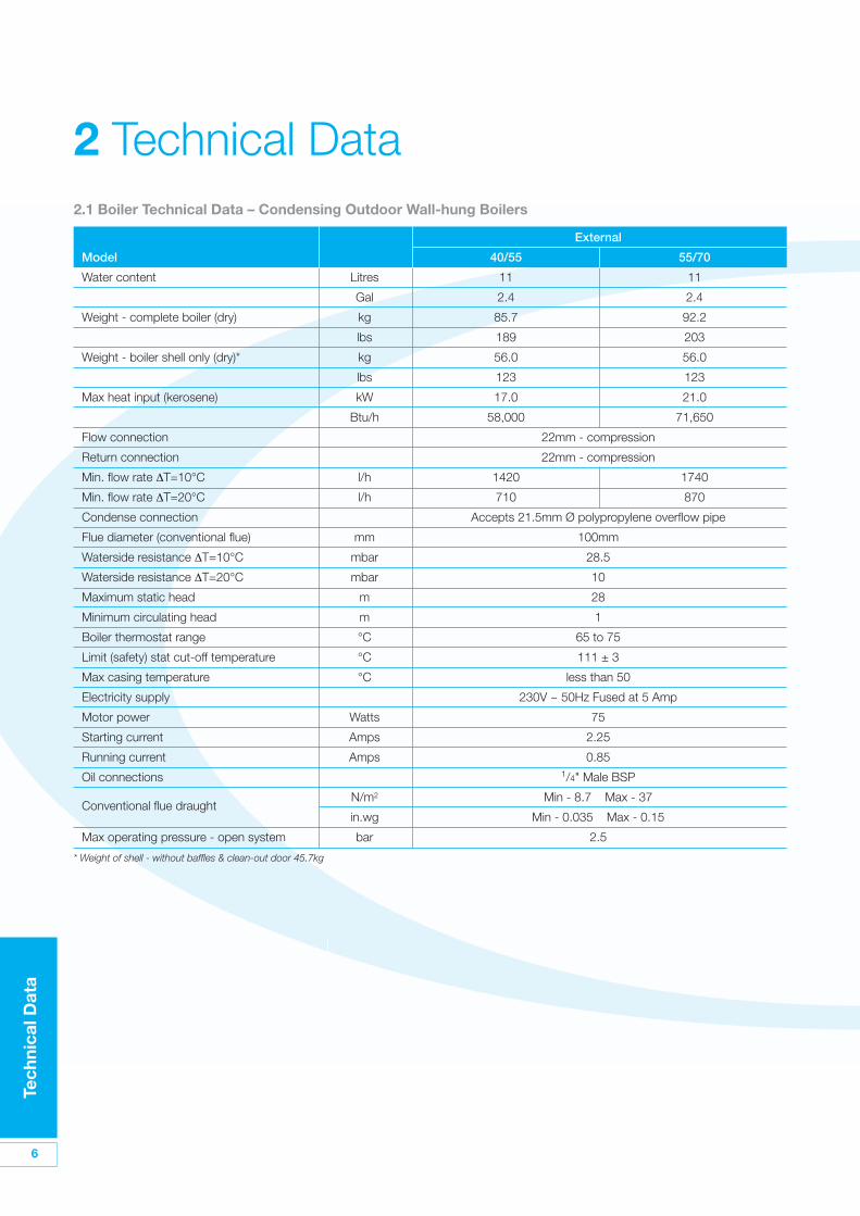
2.1 Boiler Technical Data – Condensing Outdoor Wall-hung Boilers
External
Model 40/55 55/70
Water content Litres 11 11
Gal 2.4 2.4
Weight - complete boiler (dry) kg 85.7 92.2
lbs 189 203
Weight - boiler shell only (dry)* kg 56.0 56.0
lbs 123 123
Max heat input (kerosene) kW 17.0 21.0
Btu/h 58,000 71,650
Flow connection 22mm - compression
Return connection 22mm - compression
Min. flow rate ΔT=10°C l/h 1420 1740
Min. flow rate ΔT=20°C l/h 710 870
Condense connection Accepts 21.5mm Ø polypropylene overflow pipe
Flue diameter (conventional flue) mm 100mm
Waterside resistance ΔT=10°C mbar 28.5
Waterside resistance ΔT=20°C mbar 10
Maximum static head m 28
Minimum circulating head m 1
Boiler thermostat range °C 65 to 75
Limit (safety) stat cut-off temperature °C 111 ± 3
Max casing temperature °C less than 50
Electricity supply 230V ~ 50Hz Fused at 5 Amp
Motor power Watts 75
Starting current Amps 2.25
Running current Amps 0.85
Oil connections 1/4" Male BSP
Conventional flue draughtN/m2 Min - 8.7 Max - 37
in.wg Min - 0.035 Max - 0.15
Max operating pressure - open system bar 2.5
* Weight of shell - without baffles & clean-out door 45.7kg
Tech
nica
l Dat
a
Tech
nica
l Dat
a
7
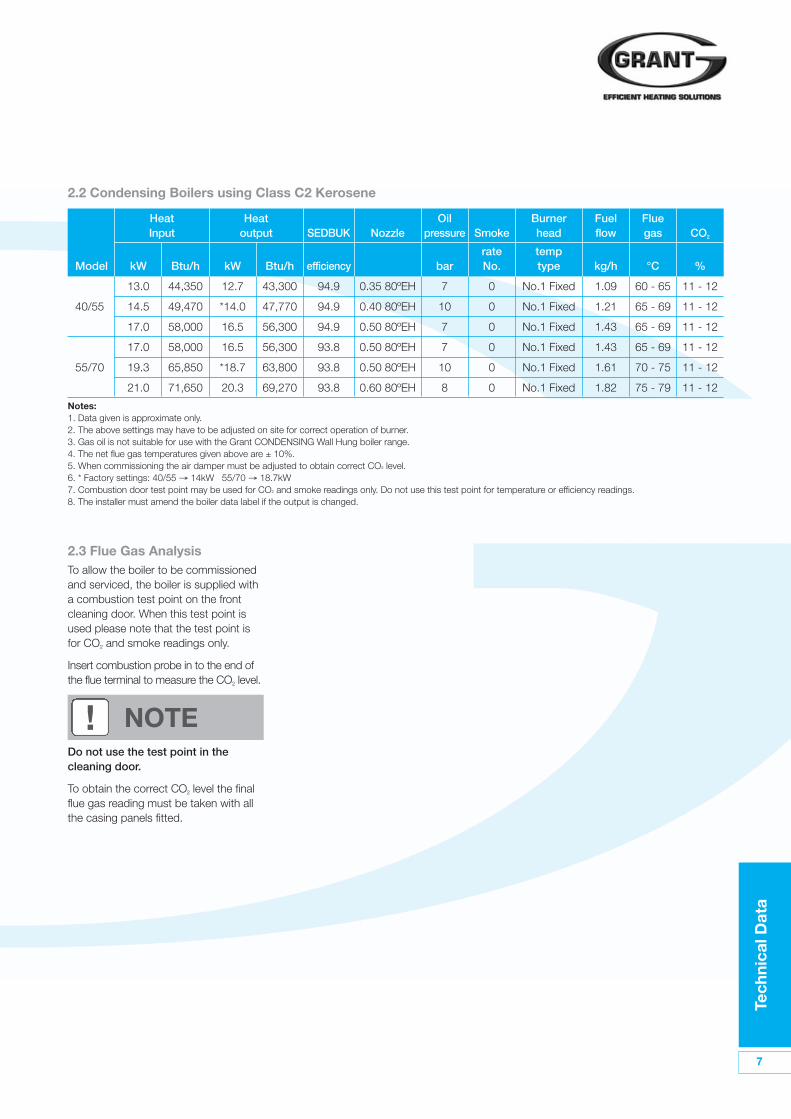
2.2 Condensing Boilers using Class C2 Kerosene
Heat Heat Oil Burner Fuel FlueInput output SEDBUK Nozzle pressure Smoke head flow gas CO2
rate tempModel kW Btu/h kW Btu/h efficiency bar No. type kg/h °C %
13.0 44,350 12.7 43,300 94.9 0.35 80ºEH 7 0 No.1 Fixed 1.09 60 - 65 11 - 12
40/55 14.5 49,470 *14.0 47,770 94.9 0.40 80ºEH 10 0 No.1 Fixed 1.21 65 - 69 11 - 12
17.0 58,000 16.5 56,300 94.9 0.50 80ºEH 7 0 No.1 Fixed 1.43 65 - 69 11 - 12
17.0 58,000 16.5 56,300 93.8 0.50 80ºEH 7 0 No.1 Fixed 1.43 65 - 69 11 - 12
55/70 19.3 65,850 *18.7 63,800 93.8 0.50 80ºEH 10 0 No.1 Fixed 1.61 70 - 75 11 - 12
21.0 71,650 20.3 69,270 93.8 0.60 80ºEH 8 0 No.1 Fixed 1.82 75 - 79 11 - 12
Notes:1. Data given is approximate only.2. The above settings may have to be adjusted on site for correct operation of burner. 3. Gas oil is not suitable for use with the Grant CONDENSING Wall Hung boiler range.4. The net flue gas temperatures given above are ± 10%.5. When commissioning the air damper must be adjusted to obtain correct CO2 level.6. * Factory settings: 40/55 → 14kW 55/70 → 18.7kW7. Combustion door test point may be used for CO2 and smoke readings only. Do not use this test point for temperature or efficiency readings.8. The installer must amend the boiler data label if the output is changed.
2.3 Flue Gas AnalysisTo allow the boiler to be commissionedand serviced, the boiler is supplied witha combustion test point on the frontcleaning door. When this test point isused please note that the test point isfor CO2 and smoke readings only.
Insert combustion probe in to the end ofthe flue terminal to measure the CO2 level.
Do not use the test point in thecleaning door.
To obtain the correct CO2 level the finalflue gas reading must be taken with allthe casing panels fitted.
! NOTE
8
Tech
nica
l Dat
a
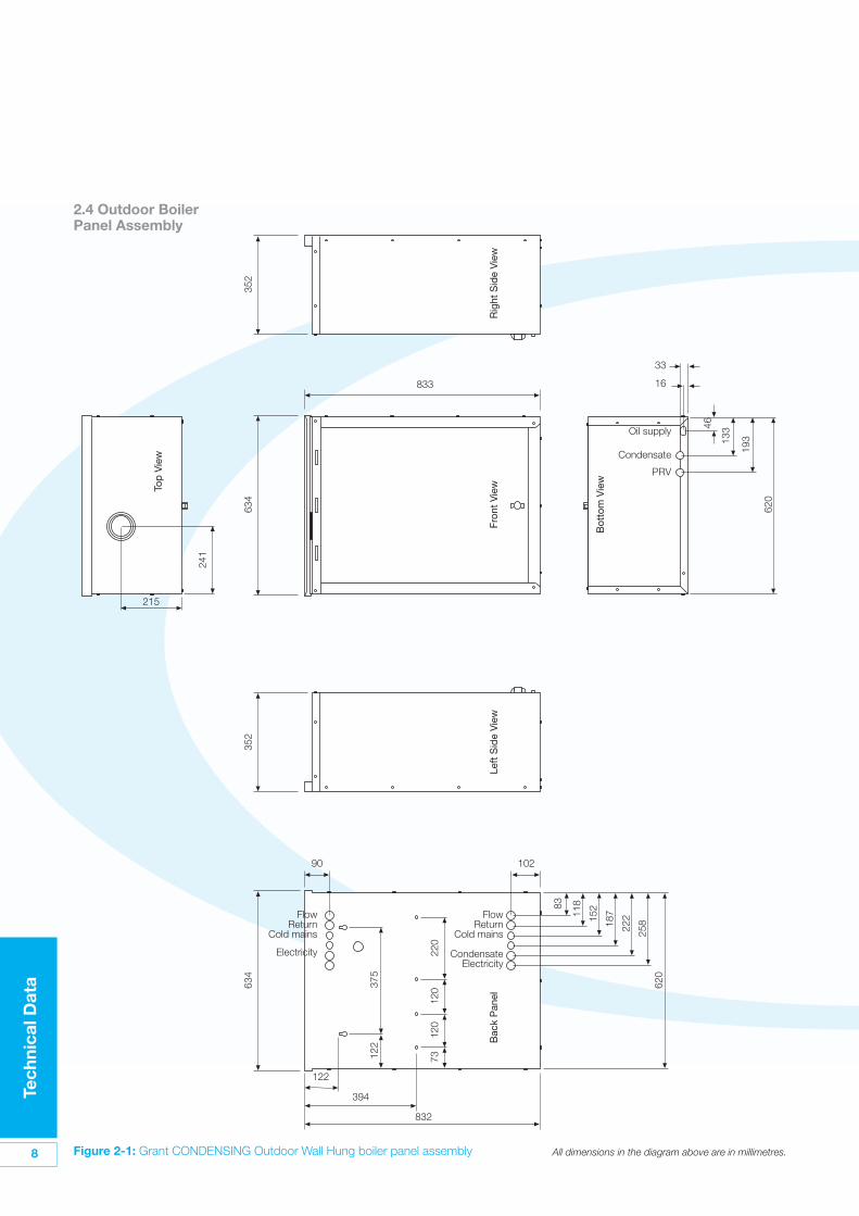
Figure 2-1: Grant CONDENSING Outdoor Wall Hung boiler panel assembly
16
33
620
19313
346
Bot
tom
Vie
w
Oil supply
Condensate
PRV
FlowReturn
Cold mains
CondensateElectricity
FlowReturn
Cold mains
Electricity
215
241
Top
Vie
w
634
122
375
220
620
258
222
187
152
11883
120
120
73
832
394
122
10290
Bac
k P
anel
352
352
Left
Sid
e V
iew
634
833
Fron
t V
iew
Rig
ht S
ide
Vie
w
2.4 Outdoor BoilerPanel Assembly
All dimensions in the diagram above are in millimetres.
Oil
Sto
rag
e &
Sup
ply
Sys
tem
9
3.1 Fuel SupplyFuel StorageThe tank should be positioned inaccordance with the recommendationsgiven in BS 5410:1:1997, which givesdetails of filling, maintenance andprotection from fire.
A steel tank may be used and must beconstructed to BS 799:5:1987 and OFST200.
A galvanized tank must not be used.
A plastic tank may be used and mustcomply with OFS T100.
Plastic tanks should be adequatelyand uniformly supported on asmooth level surface, across theirentire load bearing base area, that is,the area in contact with the ground.
Fuel PipesFuel supply pipes should be of coppertubing with an external diameter of atleast 10mm.
Galvanised pipe must not be used.
All pipe connections should preferablyuse flared fittings. Soldered connectionsmust not be used on oil pipes.
Flexible pipes must not be usedoutside the boiler case.
A remote sensing fire valve must beinstalled in the fuel supply line, with thesensing head located above the burner.
Recommendations are given inBS 5410:1:1997.
A metal bowl type filter with areplaceable micronic filter must be fittedin the fuel supply line adjacent to theboiler. A shut-off valve should be fittedbefore the filter, to allow the filter to beserviced.
Two flexible fuel lines, adaptor and 1/4"BSP isolation valve are supplied loosewith the boiler for the final connection tothe burner, with a two pipe system or'Tiger Loop' type de-aerator.
Metal braided flexible pipes should bereplaced annually when the boiler isserviced. Long life flexible pipes shouldbe inspected annually and replaced atleast every 60 months.
! CAUTION
! CAUTION
! NOTE
3 Oil Storage & Supply System
10
Oil
Sto
rag
e &
Sup
ply
Sys
tem
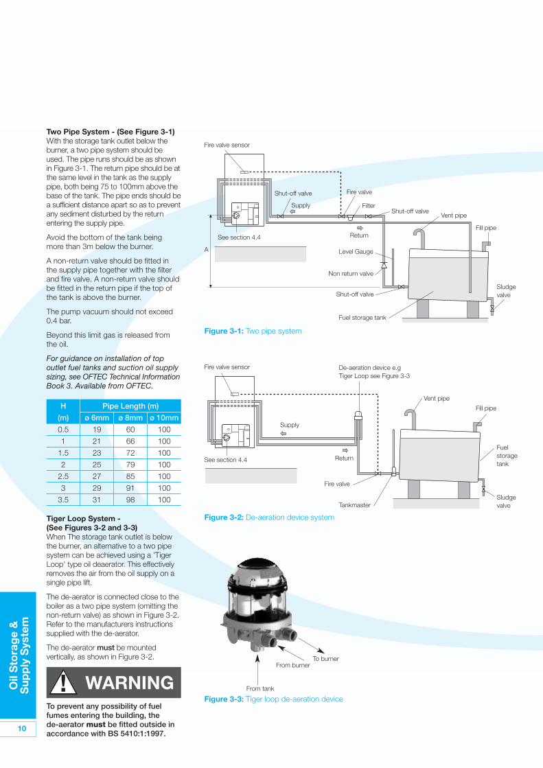
Two Pipe System - (See Figure 3-1)With the storage tank outlet below theburner, a two pipe system should beused. The pipe runs should be as shownin Figure 3-1. The return pipe should be atthe same level in the tank as the supplypipe, both being 75 to 100mm above thebase of the tank. The pipe ends should bea sufficient distance apart so as to preventany sediment disturbed by the returnentering the supply pipe.
Avoid the bottom of the tank beingmore than 3m below the burner.
A non-return valve should be fitted inthe supply pipe together with the filterand fire valve. A non-return valve shouldbe fitted in the return pipe if the top ofthe tank is above the burner.
The pump vacuum should not exceed0.4 bar.
Beyond this limit gas is released fromthe oil.
For guidance on installation of topoutlet fuel tanks and suction oil supplysizing, see OFTEC Technical InformationBook 3. Available from OFTEC.
Filter
Fire valve
Fire valve
Shut-off valve
Shut-off valve
Supply
Supply
Return
Return
A
Fire valve sensor
Fire valve sensor
Level Gauge
Non return valve
Shut-off valve
See section 4.4
Vent pipe
Vent pipe
Fill pipe
Fill pipe
Fuel storage tank
Sludgevalve
Sludgevalve
H Pipe Length (m)
(m) ø 6mm ø 8mm ø 10mm
0.5 19 60 100
1 21 66 100
1.5 23 72 100
2 25 79 100
2.5 27 85 100
3 29 91 100
3.5 31 98 100
Figure 3-1: Two pipe system
Tiger Loop System -(See Figures 3-2 and 3-3)When The storage tank outlet is belowthe burner, an alternative to a two pipesystem can be achieved using a 'TigerLoop' type oil deaerator. This effectivelyremoves the air from the oil supply on asingle pipe lift.
The de-aerator is connected close to theboiler as a two pipe system (omitting thenon-return valve) as shown in Figure 3-2.Refer to the manufacturers instructionssupplied with the de-aerator.
The de-aerator must be mountedvertically, as shown in Figure 3-2.
To prevent any possibility of fuelfumes entering the building, thede-aerator must be fitted outside inaccordance with BS 5410:1:1997.
! WARNING
Tankmaster
Fuelstoragetank
De-aeration device e.gTiger Loop see Figure 3-3
See section 4.4
Figure 3-2: De-aeration device system
Figure 3-3: Tiger loop de-aeration device
To burnerFrom burner
From tank
Oil
Sto
rag
e &
Sup
ply
Sys
tem
11
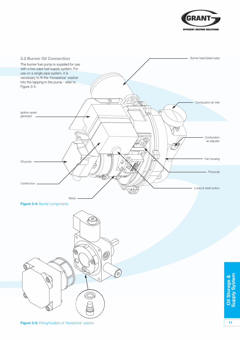
3.2 Burner Oil ConnectionThe burner fuel pump is supplied for usewith a two-pipe fuel supply system. Foruse on a single pipe system, it isnecessary to fit the ‘horseshoe’ washerinto the tapping in the pump - refer toFigure 3-5.
Figure 3-4: Burner components
Burner head (blast tube)
Combustion air inlet
Combustionair adjuster
Lockout reset button
Motor
Control box
Oil pump
Ignition sparkgenerator
Photocell
Fan housing
Figure 3-5: Fitting/location of ‘horseshoe’ washer
12
Oil
Sto
rag
e &
Sup
ply
Sys
tem
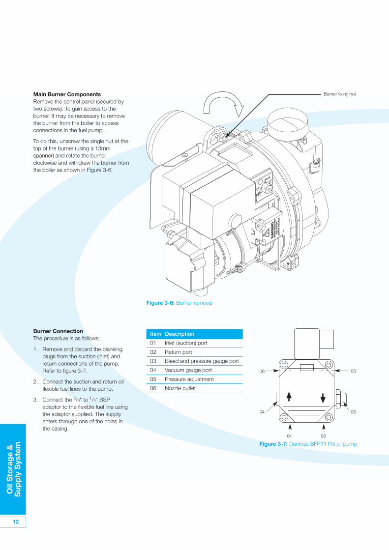
Main Burner ComponentsRemove the control panel (secured bytwo screws). To gain access to theburner. It may be necessary to removethe burner from the boiler to accessconnections in the fuel pump.
To do this, unscrew the single nut at thetop of the burner (using a 13mmspanner) and rotate the burnerclockwise and withdraw the burner fromthe boiler as shown in Figure 3-6.
Burner ConnectionThe procedure is as follows:
1. Remove and discard the blankingplugs from the suction (inlet) andreturn connections of the pump.Refer to figure 3-7.
2. Connect the suction and return oilflexible fuel lines to the pump.
3. Connect the 3/8" to 1/4" BSPadaptor to the flexible fuel line usingthe adaptor supplied. The supplyenters through one of the holes inthe casing.
Item Description
01 Inlet (suction) port
02 Return port
03 Bleed and pressure gauge port
04 Vacuum gauge port
05 Pressure adjustment
06 Nozzle outlet
Figure 3-6: Burner removal
Burner fixing nut
01
Figure 3-7: Danfoss BFP11 R3 oil pump
05
06
04
02
03
Bo
iler
Inst
alla
tio
nIn
form
atio
n
13
4 Boiler Installation Information4.1 IntroductionThe boiler is supplied already fullyassembled in a carton which is carefullypacked with packing materials. As theboiler is wall mounted all of the contentof the boiler casing must be removedwith the packaging before installationcan begin, to give access to the rearfixing panel. The installation proceduretherefore begins with unpacking anddismantling of the packed boiler.
4.2 Boiler LocationThe Module must be installed externally,fixed to an outdoor wall that is firm, flatand vertical. It does not require anyspecial base provisions as thetemperature of the boiler casing is lessthan 50°C.
The Module must be positioned suchthat the required clearances from thelow level flue outlet, as shown inFigure 9-3, are achieved.
Adequate clearance must be left aroundand in front of the Module for servicing.The Outdoor wall mounted boiler mustbe installed with the flue terminalterminating at least two metres aboveground level. (Refer to standard BS5410part 1). No terminal guard can be fittedif termination is less than two metresabove ground level. In this situation usethe Green flue system to achieve theminimum height. See Section 9.
The flue terminal must be a minimumdistance of 1.8m from an oil storagetank.
The flue terminal should be positionedso as to avoid products of combustionaccumulating in stagnant pocketsaround the building or entering intobuildings.
Once the outdoor boiler is fixedsufficient clearance must be allowed atthe front of and below the boiler toremove the burner and baffles forservicing.
4.3 Preparation for InstallationThe following procedure must beperformed before you can begindismantling the boiler for installation:
1. With boiler on pallet, open carton,remove packing and carton fromboiler.
2. Remove door - turn the handleanticlockwise and lift door awayfrom boiler, carefully sliding out fromtop flange.
3. Remove internal packaging fromwithin boiler casing.
4. Remove flue terminal and flexible oilhose packs from within boiler.
4.4 Dismantling the BoilerDismantle the boiler as follows, keepingall components, screws and washers forre-assembly:
1. Remove screws securing top paneland remove top casing panel fromboiler.
2. Disconnect burner electrical plug.
3. Unscrew inlet connection tocondensate trap and remove trapfrom boiler.
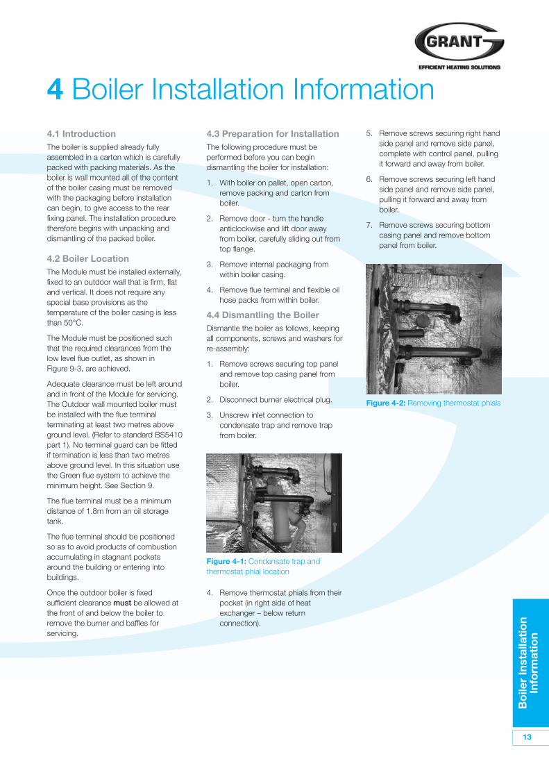
4. Remove thermostat phials from theirpocket (in right side of heatexchanger – below returnconnection).
5. Remove screws securing right handside panel and remove side panel,complete with control panel, pullingit forward and away from boiler.
6. Remove screws securing left handside panel and remove side panel,pulling it forward and away fromboiler.
7. Remove screws securing bottomcasing panel and remove bottompanel from boiler.
Figure 4-1: Condensate trap andthermostat phial location
Figure 4-2: Removing thermostat phials
14
Bo
iler
Inst
alla
tio
nIn
form
atio
n
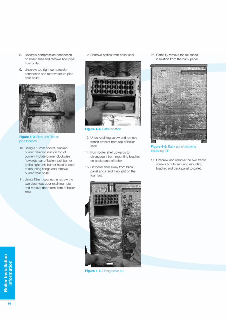
12. Remove baffles from boiler shell.
10. Using a 13mm socket, slackenburner retaining nut (on top ofburner). Rotate burner clockwise(towards rear of boiler), pull burnerto the right until burner head is clearof mounting flange and removeburner from boiler.
11. Using 13mm spanner, unscrew thetwo clean-out door retaining nutsand remove door from front of boilershell.
17. Unscrew and remove the two transitscrews & nuts securing mountingbracket and back panel to pallet.
13. Undo retaining screw and removetransit bracket from top of boilershell.
14. Push boiler shell upwards todisengage it from mounting bracketon back panel of boiler.
15. Lift boiler shell away from backpanel and stand it upright on thefour feet.
Figure 4-5: Lifting boiler out
16. Carefully remove the foil-facedinsulation from the back panel.
Figure 4-6: Back panel showinginsulating foil
Figure 4-4: Baffle location
8. Unscrew compression connectionon boiler shell and remove flow pipefrom boiler.
9. Unscrew top right compressionconnection and remove return pipefrom boiler.
Figure 4-3: Flow and Returnpipe location
Bo
iler
Inst
alla
tio
nIn
form
atio
n
15
3. Mark the position of the fourmounting bracket fixings on to thewall from the back panel. Also markthe positions of the flow and returnpipes, the cold mains (for fillingloop), the electrical power supply,and the condensate discharge pipe.
4. Remove the back panel from thewall. Drill the holes for the mountingbracket fixings and fit the wall plugsprovided. Drill all other necessaryholes. Re-mount the back panel onthe two keyhole slots.
5. Locate mounting bracket onto backpanel, aligning four holes in bracketwith those in back panel. Ensurethat mounting ‘hooks’ are pointingupwards and secure using thefixings supplied.
6. Carefully re-fit insulation into backpanel, passing mounting ‘hooks’through the two slits in theinsulation.
7. Lift boiler shell and hang it on themounting bracket – ensuring thatthe mounting plates on either side ofthe shell are fully located in thevertical slot of both mounting hooks.
8. Re-fit return pipe to top right handconnection on boiler shell. Passreturn pipe from system throughhole in wall and connect to boilerreturn pipe.
9. Re-fit flow pipe to compressionconnection on boiler shell. Pass flowpipe from system through hole inwall and connect to boiler flow pipe.
10. Re-fit burner. First remove burnersecuring nut, locate burner headinto hole in burner flange/boiler shelland locate mounting screw throughhole on top of burner. Re-fit nut andtighten to secure burner in place.Connect flexible oil lines from oilsupply pipework to burner. It isrecommended that the copper oillines are installed at this stage whilethe side panels are not in place.
11. Re-fit baffles into boiler shell –ensuring they are in the correctorder (check marking on each baffle)as shown below:
13. Locate clean-out door onto the twostuds, re-fit nuts and tighten tosecure door in place.
Figure 4-8: Re-fitting baffles intoboiler shell
4.5 Installing the Boiler
The boiler must be mounted suchthat the boiler flue terminal (suppliedwith the boiler) terminates at orabove 2 metres above ground level.
If this distance is to be less than this,Grant suggest using the Green systemto achieve a termination point of atleast 2 metres above ground level.
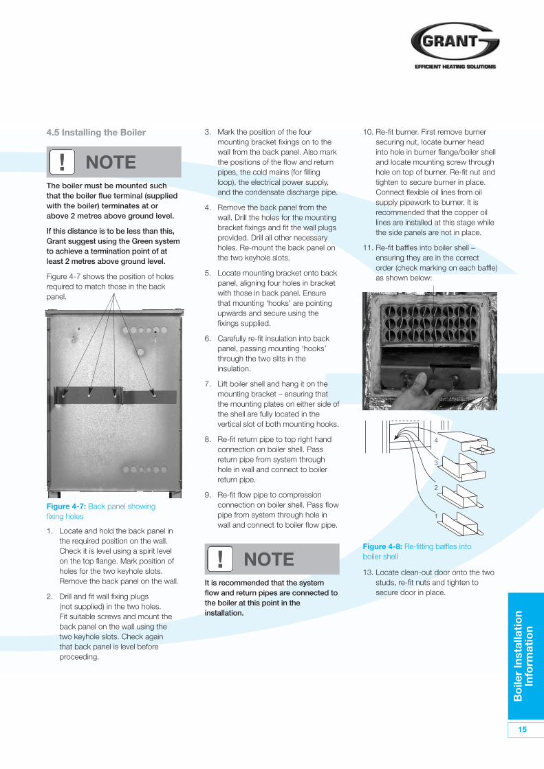
Figure 4-7 shows the position of holesrequired to match those in the backpanel.
1. Locate and hold the back panel inthe required position on the wall.Check it is level using a spirit levelon the top flange. Mark position ofholes for the two keyhole slots.Remove the back panel on the wall.
2. Drill and fit wall fixing plugs(not supplied) in the two holes.Fit suitable screws and mount theback panel on the wall using thetwo keyhole slots. Check againthat back panel is level beforeproceeding.
! NOTE
It is recommended that the systemflow and return pipes are connected tothe boiler at this point in theinstallation.
! NOTE
1
2
3
4
Figure 4-7: Back panel showingfixing holes
16
Bo
iler
Inst
alla
tio
nIn
form
atio
n
Failure to install and commissionappliances correctly may invalidatethe boiler warranty.
Before starting any work on theboiler, or fuel supply please read thehealth and safety information given inSection 14.
! NOTE
! WARNING
14. Re-fit left hand casing panel andsecure in place with screws (withwashers).
15. Re-fit bottom casing panel andsecure in place with screws (withwashers).
16. Re-fit right hand casing panelcomplete with control panel fitted.
17. Re-locate thermostat bulbs inpocket at rear right hand side ofboiler shell.
18. Re-connect burner plug.
19. Re-fit condensate trap. Connectcondensate discharge pipe to outletof trap. See also ‘CondensateDisposal’.
20. Re-fit top casing panel and securein place with screws (with washers).
21. Fit flue terminal, carefully pushing itthrough seal in hole in top panel.Ensure that seal is fitted to terminaland that it is pushed fully home intothe flue connector on the boilershell. Position the outlet to point tothe left and at an angle of 45° awayfrom the wall.
22. Re-fit front casing panel – locate topedge up under front flange of toppanel. Push bottom of front panelinto opening until flush with edge ofside panels before rotating handleclockwise to secure.
4.6 Regulations ComplianceInstallation of a Grant CONDENSINGOutdoor Wall Hung boiler must be inaccordance with the followingrecommendations:-
• Local Building Regulations andbuilding standards issued by theDepartment of the Environment andany local Byelaws which you mustcheck with the local authority for thearea.
• Model and local Water UndertakingByelaws.
• Applicable Control of PollutionRegulations.
• The following OFTEC requirements:
- OFS T100 Polythene oil storagetanks for distillate fuels.
- OFS T200 Fuel oil storage tanksand tank bunds for use withdistillate fuels, lubrication oils andwaste oils.
Further information may be obtainedfrom the OFTEC Technical InformationBook 3 (Installation requirements for oilfired boilers and oil storage tanks).
The installation should also be inaccordance with the latest edition of thefollowing British Standard Codes ofPractice:
• BS 715 Metal flue pipes, fittings,terminals and accessories.
• BS 799:5 Oil storage tanks.
• BS 1181 Clay flue linings and flueterminals.
• BS 4543:3 Factory made insulatedchimneys for oil fired appliances.
• BS 4876 Performance requirementsfor oil burning appliances.
• BS 5410:1 Code of Practice for oilfiring appliances.
• BS 5449 Forced circulation hotwater systems.
• BS 7593 Code of Practice fortreatment of water in heatingsystems.
• BS 7671 Requirements for electricalinstallations, IEE Wiring Regulations.
Bo
iler
Inst
alla
tio
nIn
form
atio
n
17
4.11 Pipework MaterialsGrant boilers are compatible with bothcopper and plastic pipe. Where plasticpipe is used it must be of the oxygenbarrier type and be of the correct class(to BS 7291:Part 1:1990) for theapplication concerned.
4.9 Heating System DesignConsiderationsTo achieve the maximum efficiencypossible from the Grant CONDENSINGOutdoor Wall Hung boiler, the heatingsystem should be designed to thefollowing parameters:
Radiators:-• Flow temperature 70°C
• Return temperature 50°C
• Differential 20°C
Underfloor:-• Flow temperature 50°C
• Return temperature 40°C
• Differential 10°C
Size radiators with a mean watertemperature of 60°C.
Design system controls withprogrammable room thermostats or useweather compensating controls tomaintain return temperatures below55°C.
The boiler should not be allowed tooperate with return temperatures ofless than 40°C when the system is upto operating temperature.
The use of a pipe stat is recommendedto control the return temperature whenusing weather compensating controls.
4.10 Underfloor Heating SystemsIn underfloor systems it is essentialthat the return temperature must bemaintained above 40°C to preventinternal corrosion of the boiler waterjacket.
4.7 CompletionPlease ensure that the OFTEC CD/10installation completion report (providedwith the boiler) is completed in full.
Leave the top copy with the User.
Retain the carbon copy.
Ensure that the User Information pack(supplied with the boiler) is handed overto the Householder.
4.8 Before you CommissionTo avoid the danger of dirt and foreignmatter entering the boiler the completeheating system should be thoroughlyflushed out - before the boiler isconnected and then again after thesystem has been heated and is still hot.This is especially important where theboiler is used on an old system.
For optimum performance afterinstallation, this boiler and its associatedcentral heating system must be flushedin accordance with the guidelines givenin BS 7593:1992 'Treatment of water indomestic hot water central heatingsystems'.
This must involve the use of aproprietary cleaner, such asBetzDearborn's Sentinel X300 or X400,or Fernox Restorer. Full instructions aresupplied with the products, but for moredetails of BetzDearborn’s products, viewthe website www.sentinel-solutions.netand for more details of Fernox productsview the website www.fernox.com.
For Long term protection againstcorrosion and scale, after flushing, it isrecommended that an inhibitor such asBetzdearborn's Sentinel X100 or FernoxMB-1 is dosed in accordance with theguidelines given in BS 7593:1992.
Failure to implement these guidelineswill invalidate the warranty.
The system should incorporate alow-pressure switch to shut offpower to the boiler if the systempressure drops below 0.2 bar. Asuitable low pressure switch kit isavailable to purchase from GrantEngineering (IRELAND) Limited, PartNo. MPCBS 62.
4.12 Underfloor PipeworkPlastic pipe may be used on Underfloorsystems where the plastic pipe is fittedafter the thermostatic mixing valve.Copper tube must be used for at leastthe first metre of flow and return primarypipework between the boiler and theunderfloor mixing/blending valves.
The first metre of pipeworkconnected to both the heating flowand return connections of the boilermust be made in copper on all typesof system - sealed or open-vented.
! NOTE
! WARNING
5 Pipe Connections
18
Pip
e C
onn
ecti
ons
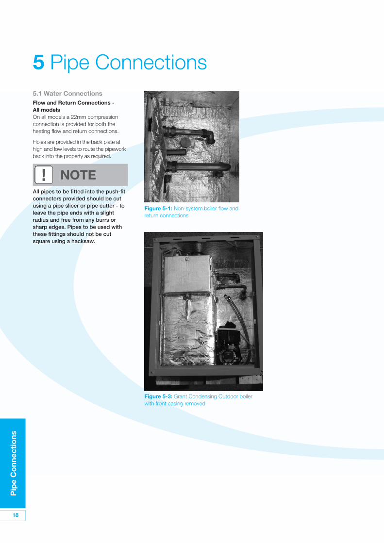
5.1 Water ConnectionsFlow and Return Connections -All modelsOn all models a 22mm compressionconnection is provided for both theheating flow and return connections.
Holes are provided in the back plate athigh and low levels to route the pipeworkback into the property as required.
All pipes to be fitted into the push-fitconnectors provided should be cutusing a pipe slicer or pipe cutter - toleave the pipe ends with a slightradius and free from any burrs orsharp edges. Pipes to be used withthese fittings should not be cutsquare using a hacksaw.
Figure 5-1: Non-system boiler flow andreturn connections
Figure 5-3: Grant Condensing Outdoor boilerwith front casing removed
! NOTE
Co
nden
sate
D
isp
osa
l
19
6 Condensate Disposal6.1 General RequirementsWhen in condensing mode the GrantCondensing wall-hung boilers producecondensate from the water vapour in theflue gases. This condensate is slightlyacidic with a ph value of around 3(similar to vinegar). Provision must bemade for the safe and effective disposalof this condensate.
Condensate can be disposed of usingone of the following methods ofconnection:
Internal Connection (preferred option):• Into an internal domestic waste
system (from kitchen sink, washingmachine, etc.).
• Directly into the soil stack
External Connection:• Into an external soil stack
• Into an external drain or gulley
• Into a rainwater hopper (that is partof a combined system where sewercaries both rainwater and foul water)
• Purpose made soakaway
All condensate disposal pipes mustbe fitted with a trap - whether they areconnected internally or externally to adomestic waste system/soil stack or runexternally to a gully, hopper or soakaway.
6.2 ConnectionsConnections into a rainwater hopper,external drain or gulley should beterminated inside the hopper/drain/gulley below the grid level butabove the water level.
Condensate disposal pipes should notbe connected directly into rainwaterdownpipes or to waste/soil systemsconnected to septic tanks.
Condensate should not be dischargedinto ’grey water’ systems that re-usewater used in the home (not includingwater from toilets).
It should be noted that connection of acondensate pipe to the drain may besubject to local Building Controlrequirement.
6.3 PipeworkCondensate disposal pipework mustbe plastic (plastic waste or overflowpipe is suitable).
Copper or steel pipe is not suitableand must not be used.
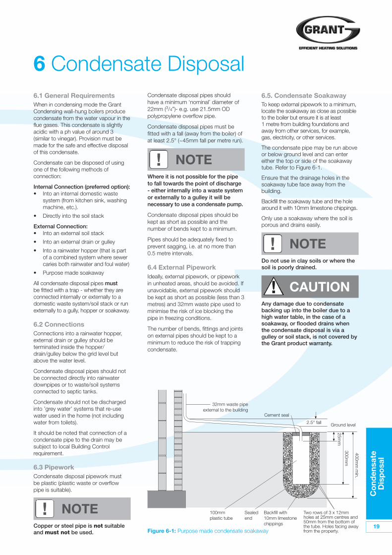
6.5. Condensate SoakawayTo keep external pipework to a minimum,locate the soakaway as close as possibleto the boiler but ensure it is at least1 metre from building foundations andaway from other services, for example,gas, electricity, or other services.
The condensate pipe may be run aboveor below ground level and can entereither the top or side of the soakawaytube. Refer to Figure 6-1.
Ensure that the drainage holes in thesoakaway tube face away from thebuilding.
Backfill the soakaway tube and the holearound it with 10mm limestone chippings.
Only use a soakaway where the soil isporous and drains easily.
Any damage due to condensatebacking up into the boiler due to ahigh water table, in the case of asoakaway, or flooded drains whenthe condensate disposal is via agulley or soil stack, is not covered bythe Grant product warranty.
Do not use in clay soils or where thesoil is poorly drained.
Where it is not possible for the pipeto fall towards the point of discharge- either internally into a waste systemor externally to a gulley it will benecessary to use a condensate pump.
Condensate disposal pipes should bekept as short as possible and thenumber of bends kept to a minimum.
Pipes should be adequately fixed toprevent sagging, i.e. at no more than0.5 metre intervals.
6.4 External PipeworkIdeally, external pipework, or pipeworkin unheated areas, should be avoided. Ifunavoidable, external pipework shouldbe kept as short as possible (less than 3metres) and 32mm waste pipe used tominimise the risk of ice blocking thepipe in freezing conditions.
The number of bends, fittings and jointson external pipes should be kept to aminimum to reduce the risk of trappingcondensate.
! NOTE
! NOTE
! NOTE
! CAUTION
Figure 6-1: Purpose made condensate soakaway
32mm waste pipeexternal to the building
Two rows of 3 x 12mmholes at 25mm centres and50mm from the bottom ofthe tube. Holes facing awayfrom the property.
Backfill with10mm limestonechippings
Sealedend
100mmplastic tube
Cement seal
Ground level2.5° fall
25mm
300mm
400mm
min.
Condensate disposal pipes shouldhave a minimum ‘nominal’ diameter of22mm (3/4”)- e.g. use 21.5mm ODpolypropylene overflow pipe.
Condensate disposal pipes must befitted with a fall (away from the boiler) ofat least 2.5° (~45mm fall per metre run).
20
Co
nden
sate
D
isp
osa
l
6.7. Condensate DisposalPipeworkThe boiler is supplied with a flexibleplastic condense disposal pipe, factory-fitted to the outlet of the trap.
This flexible discharge pipe must berouted through the boiler to exit via oneof the pre-cut ‘knock-outs’ in thebottom flange of the boiler back panel -at the right rear of the bottom casing.
Push out the ‘knock-out’ from the holetaking care not to distort the back panelflange.
The outlet end of this flexible pipe willaccept 21.5mm OD to 23mm ODPolypropylene overflow pipe forconnection of the condensate dischargepipe below the boiler.
When connecting plastic dischargepipe, ensure that the pipe is fullypushed into the outlet end connectoron the flexible pipe to prevent thepossibility of leakage.
6.8 Inspection and Cleaningof TrapThe trap must be checked at regularintervals (e.g. on every annual service)and cleaned as necessary to ensurethat it is clear and able to operate.
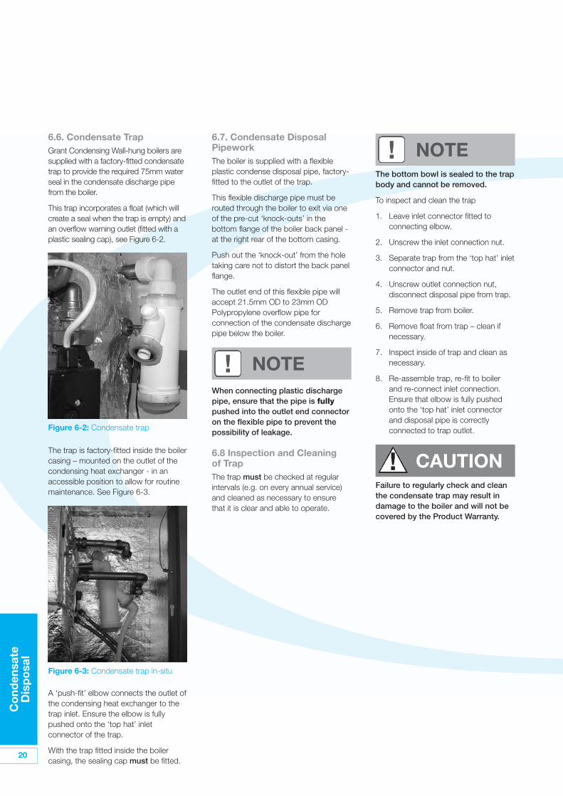
6.6. Condensate Trap Grant Condensing Wall-hung boilers aresupplied with a factory-fitted condensatetrap to provide the required 75mm waterseal in the condensate discharge pipefrom the boiler.
This trap incorporates a float (which willcreate a seal when the trap is empty) andan overflow warning outlet (fitted with aplastic sealing cap), see Figure 6-2.
The trap is factory-fitted inside the boilercasing – mounted on the outlet of thecondensing heat exchanger - in anaccessible position to allow for routinemaintenance. See Figure 6-3.
A ‘push-fit’ elbow connects the outlet ofthe condensing heat exchanger to thetrap inlet. Ensure the elbow is fullypushed onto the ‘top hat’ inletconnector of the trap.
With the trap fitted inside the boilercasing, the sealing cap must be fitted.
Figure 6-2: Condensate trap
Figure 6-3: Condensate trap in-situ
The bottom bowl is sealed to the trapbody and cannot be removed.
To inspect and clean the trap
1. Leave inlet connector fitted toconnecting elbow.
2. Unscrew the inlet connection nut.
3. Separate trap from the ‘top hat’ inletconnector and nut.
4. Unscrew outlet connection nut,disconnect disposal pipe from trap.
5. Remove trap from boiler.
6. Remove float from trap – clean ifnecessary.
7. Inspect inside of trap and clean asnecessary.
8. Re-assemble trap, re-fit to boilerand re-connect inlet connection.Ensure that elbow is fully pushedonto the ‘top hat’ inlet connectorand disposal pipe is correctlyconnected to trap outlet.
! NOTE
Failure to regularly check and cleanthe condensate trap may result indamage to the boiler and will not becovered by the Product Warranty.
! NOTE
! CAUTION
Ele
ctri
cal
21
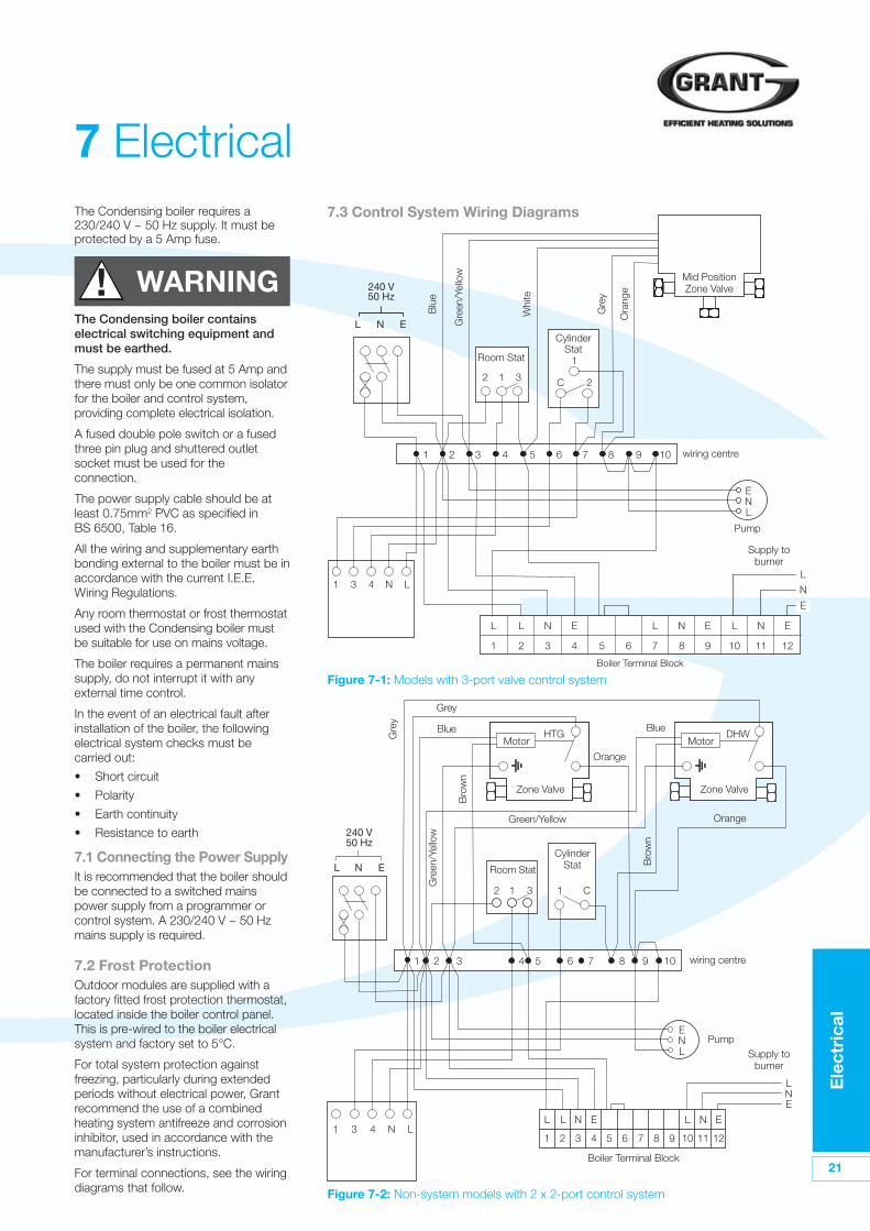
7.3 Control System Wiring Diagrams
Figure 7-2: Non-system models with 2 x 2-port control system
Room Stat
Gre
y
Whi
te
Gre
en/Y
ello
w
Blu
e
Ora
nge
CylinderStat
Mid PositionZone Valve
wiring centre
Supply toburner
Boiler Terminal Block
Pump
240 V50 Hz
L
1 3 4 N L
N E
L L N E
1
1 2
2 1
1
C 23
3 4 5 6 7 8 9 10
2 3 4 5 6
L
7
N
8
E
9
L
10
N
11
E
12
L
E
N
ENL
Grey
Blue Blue
Room Stat
Bro
wn
Bro
wn
Gre
en/Y
ello
w
Green/Yellow
Gre
y
Orange
Zone Valve Zone Valve
Motor MotorDHWHTG
Orange
CylinderStat
wiring centre
Supply toburner
Boiler Terminal Block
Pump
240 V50 Hz
L
1 3 4 N L
N E
L L N E
1 2 3 4 7 8 9
L
10
N
11
E
125 6
1 2
2 1 1 C3
3 4 5 6 7 8 9 10
EN
ENL
Figure 7-1: Models with 3-port valve control system
7 Electrical
L
The Condensing boiler containselectrical switching equipment andmust be earthed.
The supply must be fused at 5 Amp andthere must only be one common isolatorfor the boiler and control system,providing complete electrical isolation.
A fused double pole switch or a fusedthree pin plug and shuttered outletsocket must be used for theconnection.
The power supply cable should be atleast 0.75mm2 PVC as specified inBS 6500, Table 16.
All the wiring and supplementary earthbonding external to the boiler must be inaccordance with the current I.E.E.Wiring Regulations.
Any room thermostat or frost thermostatused with the Condensing boiler mustbe suitable for use on mains voltage.
The boiler requires a permanent mainssupply, do not interrupt it with anyexternal time control.
In the event of an electrical fault afterinstallation of the boiler, the followingelectrical system checks must becarried out:
• Short circuit
• Polarity
• Earth continuity
• Resistance to earth
7.1 Connecting the Power SupplyIt is recommended that the boiler shouldbe connected to a switched mainspower supply from a programmer orcontrol system. A 230/240 V ~ 50 Hzmains supply is required.
7.2 Frost ProtectionOutdoor modules are supplied with afactory fitted frost protection thermostat,located inside the boiler control panel.This is pre-wired to the boiler electricalsystem and factory set to 5°C.
For total system protection againstfreezing, particularly during extendedperiods without electrical power, Grantrecommend the use of a combinedheating system antifreeze and corrosioninhibitor, used in accordance with themanufacturer’s instructions.
For terminal connections, see the wiringdiagrams that follow.
The Condensing boiler requires a230/240 V ~ 50 Hz supply. It must beprotected by a 5 Amp fuse.
! WARNING
22
Ele
ctri
cal
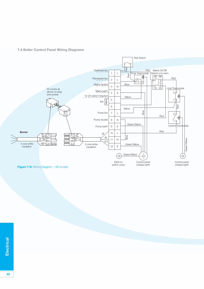
7.4 Boiler Control Panel Wiring Diagrams
4 core whiteinsulation
Burner
3 core whiteinsulation
Fit covers asabove on plugand socket
Red
Test Switch
Frost Thermostat
Earth toswitch cover
Control panelchassis earth
Control panelchassis earth
Limit Thermostat
Control Thermostat
Mains On/OffSwitch c/w neon
Red
Red
Red
Blue
Blu
e
Blu
e
Switched live
Pump live
Mains neutral
Pump neutral
Pump earth
Mains earth
link
To CH valve if required
Permanent live
Yellow
Yellow
Green/Yellow
Green/Yellow
Gre
en/Y
ello
w
Green/Yellow
Yello
w
Red
Red
Red
12
4B 5B
C
2
C
1
1A 2A
Br BrL1
NL2
L1
NL2
Bl
Blk
G/YBlG/Y
Br
1 L
2 L
3 N
4 E
5
6
7 L
8 N
9 E
10 L
11 N
12 E
Bl
G/Y
Figure 7-6: Wiring Diagram – All models
Flue
Sys
tem
and
Air
Sup
ply
23
8 Flue System and Air SupplyThe boiler is supplied with a flue terminal.Refer to Section 4.5 for fitting details.
As an alternative to the terminal suppliedthere are two external flue systems that canbe used with the Outdoor wall Hung boiler,both available from your local stockists:
• Grant Green System – This verticaltwin wall stainless steel insulatedsystem replaces the low levelterminal supplied with the boiler, andmay terminate at high level orvertically as required.
8.1 Air SupplyA sufficient permanent air supply to theboiler should be provided for propercombustion of fuel and effectivedischarge of combustion products tothe open air.
Grant module boilers draw their airsupply via the ventilation holes in thebottom of the boiler casing. These mustnot be obstructed.
Further details may be obtained fromBS 5410:1:1997.
8.2 Conventional Flue Systems
Grant condensing boilers have highoperating efficiencies and low flue gastemperatures. Care must be taken toensure the flue system is suitable for thevery low flue gas temperatures andcondensate in the flue gases.
The flue must terminate in a downdraught free area, i.e. at least 600mmabove the point of exit through the roofor preferably above the ridge level.
The condensate may be allowed to runback into the boiler. A condensate drain atthe base of the flue system is not required.
The high level flue terminal must be atleast 600mm from any opening into thebuilding, and 600mm above any verticalstructure or wall less than a horizontaldistance of 750mm from the terminal.
If an existing chimney is to be used, it mustbe lined with a smooth bore stainless steelliner suitable for use with oil firedcondensing boilers. The top and bottom ofthe annular space must be sealed.
The internal flue liner diameter for allmodels must be 100mm (4 in).
Grant recommends the use of the Grant'Orange' flue system components forthis application.
Twin-wall flues are recommended forexternally run flues to reduce thepossibility of the condensate freezing inthe flue.
No part of any flue system should bemade of an asbestos material;aluminium must not be used in any partof the flue. Only stainless steel fluecomponents should be used.
If the draught conditions aresatisfactory, the flue should terminatewith a standard cowl.
Refer to the locally applicable BuildingRegulations, BS 5410:1 and OFTECInstallation Requirements (OFTECBooks 2 and 3) for further guidance onconventional flue systems.
Under no circumstances can GrantCondensing boilers be installed withexisting flue systems. Only fluesystems and components suitable forwet flues should be used.
Failure to install the correct type of fluesystem will invalidate the warranty.
! NOTE
It is important to ensure that the fluesystem is sealed and that condensatecannot escape. Up to 1.5 l/h ofcondensate can be produced in aconventional flue system.
Do not use fire cement. The use of hightemperature silicone sealants isrecommended.
8.3 External Conventional Flue(Green System)The external system can terminate ateither high level or vertically (above rooflevel) as required. The vertical or high levelterminal must terminate in accordancewith BS 5410: Part 1. The minimumdimensions for locating the high levelterminal from building features (windows,doors, etc.) are shown in Figure 9-3.
The Green system comprises of fiveinsulated extension lengths, 45° elbows,a vertical terminal and a high levelhorizontal terminal. Locking bands areprovided with all vertical extensions andterminals. Ensure that the lockingbands are fitted.
Two types of wall bracket are alsoavailable (standard and adjustable) tosupport the vertical flue components.
The maximum vertical height (from the topof the boiler to the terminal) for the100mm diameter ‘Green’ system twin-wall flue is 8 metres. Only two 45° elbowsmay be used in the complete system.
If the flue terminal is fitted less than 2metres above a surface to which peoplehave access, the terminal must beprotected by a guard. The guard must bemanufactured from stainless steel andshould be fitted centrally over the flueterminal and securely fixed to the wall.
! CAUTION
24
Flue
Sys
tem
and
A
ir S
upp
ly
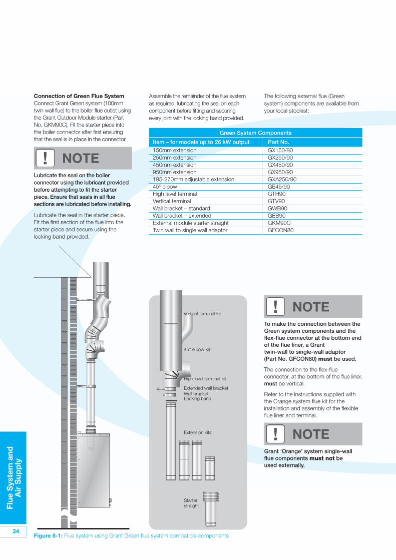
The following external flue (Greensystem) components are available fromyour local stockist:
Assemble the remainder of the flue systemas required, lubricating the seal on eachcomponent before fitting and securingevery joint with the locking band provided.
Green System Components
Item – for models up to 26 kW output Part No.150mm extension GX150/90250mm extension GX250/90450mm extension GX450/90950mm extension GX950/90195-270mm adjustable extension GXA250/9045º elbow GE45/90High level terminal GTH90Vertical terminal GTV90Wall bracket – standard GWB90Wall bracket – extended GEB90External module starter straight GKM90CTwin wall to single wall adaptor GFCON80
Figure 8-1: Flue system using Grant Green flue system compatible components
Vertical terminal kit
45° elbow kit
High level terminal kit
Extended wall bracket
Extension kits
Starterstraight
Wall bracketLocking band
Connection of Green Flue SystemConnect Grant Green system (100mmtwin wall flue) to the boiler flue outlet usingthe Grant Outdoor Module starter (PartNo. GKM90C). Fit the starter piece intothe boiler connector after first ensuringthat the seal is in place in the connector.
Lubricate the seal on the boilerconnector using the lubricant providedbefore attempting to fit the starterpiece. Ensure that seals in all fluesections are lubricated before installing.
Lubricate the seal in the starter piece.Fit the first section of the flue into thestarter piece and secure using thelocking band provided.
! NOTE
To make the connection between theGreen system components and theflex-flue connector at the bottom endof the flue liner, a Granttwin-wall to single-wall adaptor(Part No. GFCON80) must be used.
The connection to the flex-flueconnector, at the bottom of the flue liner,must be vertical.
Refer to the instructions supplied withthe Orange system flue kit for theinstallation and assembly of the flexibleflue liner and terminal.
! NOTE
Grant ‘Orange’ system single-wallflue components must not beused externally.
! NOTE
Flue
Sys
tem
and
A
ir S
upp
ly
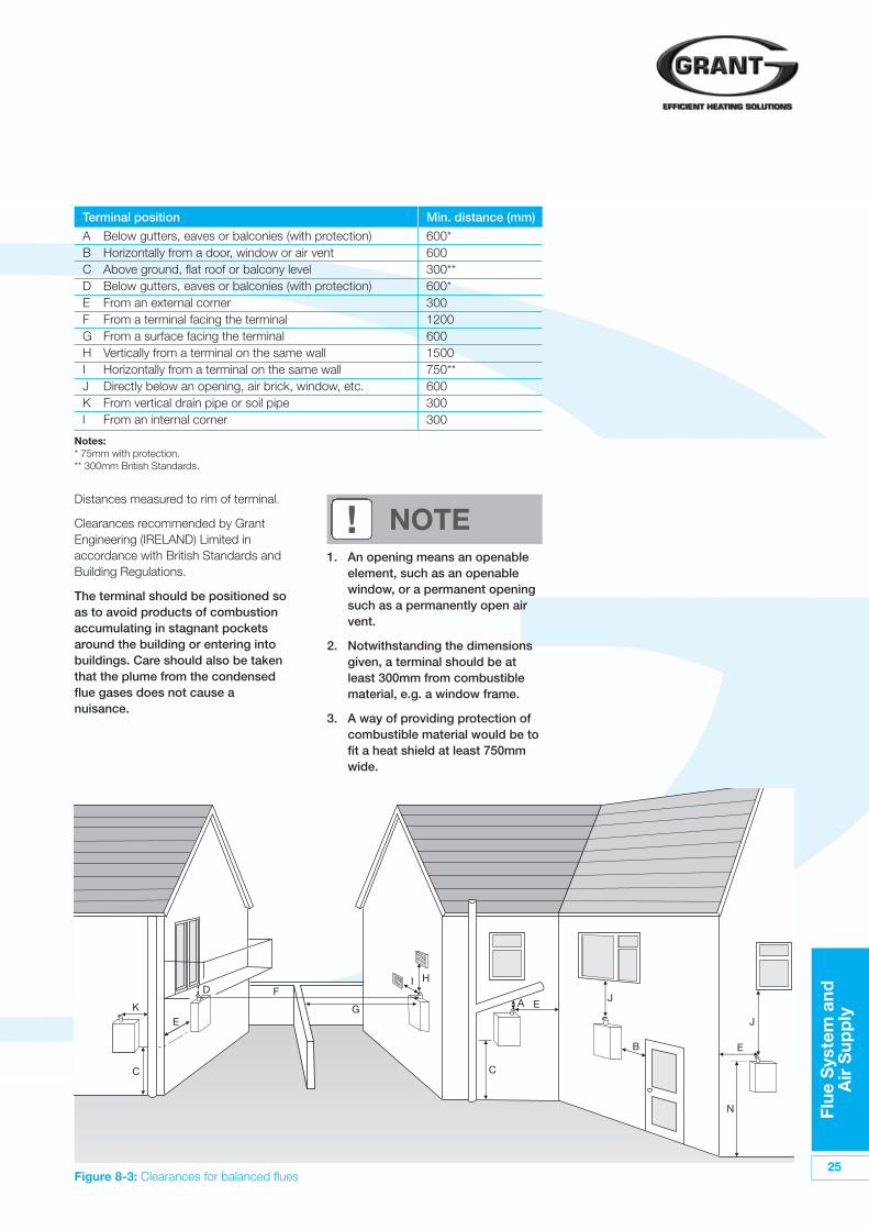
25Figure 8-3: Clearances for balanced flues
Terminal position Min. distance (mm)
A Below gutters, eaves or balconies (with protection) 600*B Horizontally from a door, window or air vent 600C Above ground, flat roof or balcony level 300**D Below gutters, eaves or balconies (with protection) 600*E From an external corner 300F From a terminal facing the terminal 1200G From a surface facing the terminal 600H Vertically from a terminal on the same wall 1500I Horizontally from a terminal on the same wall 750**J Directly below an opening, air brick, window, etc. 600K From vertical drain pipe or soil pipe 300l From an internal corner 300
Notes:* 75mm with protection.** 300mm British Standards.
D
K
C
F
B
E
N
A E
E
C
GJ
J
HI
1. An opening means an openableelement, such as an openablewindow, or a permanent openingsuch as a permanently open airvent.
2. Notwithstanding the dimensionsgiven, a terminal should be atleast 300mm from combustiblematerial, e.g. a window frame.
3. A way of providing protection ofcombustible material would be tofit a heat shield at least 750mmwide.
! NOTEDistances measured to rim of terminal.
Clearances recommended by GrantEngineering (IRELAND) Limited inaccordance with British Standards andBuilding Regulations.
The terminal should be positioned soas to avoid products of combustionaccumulating in stagnant pocketsaround the building or entering intobuildings. Care should also be takenthat the plume from the condensedflue gases does not cause anuisance.
26
Co
mm
issi
oni
ng
9 Commissioning
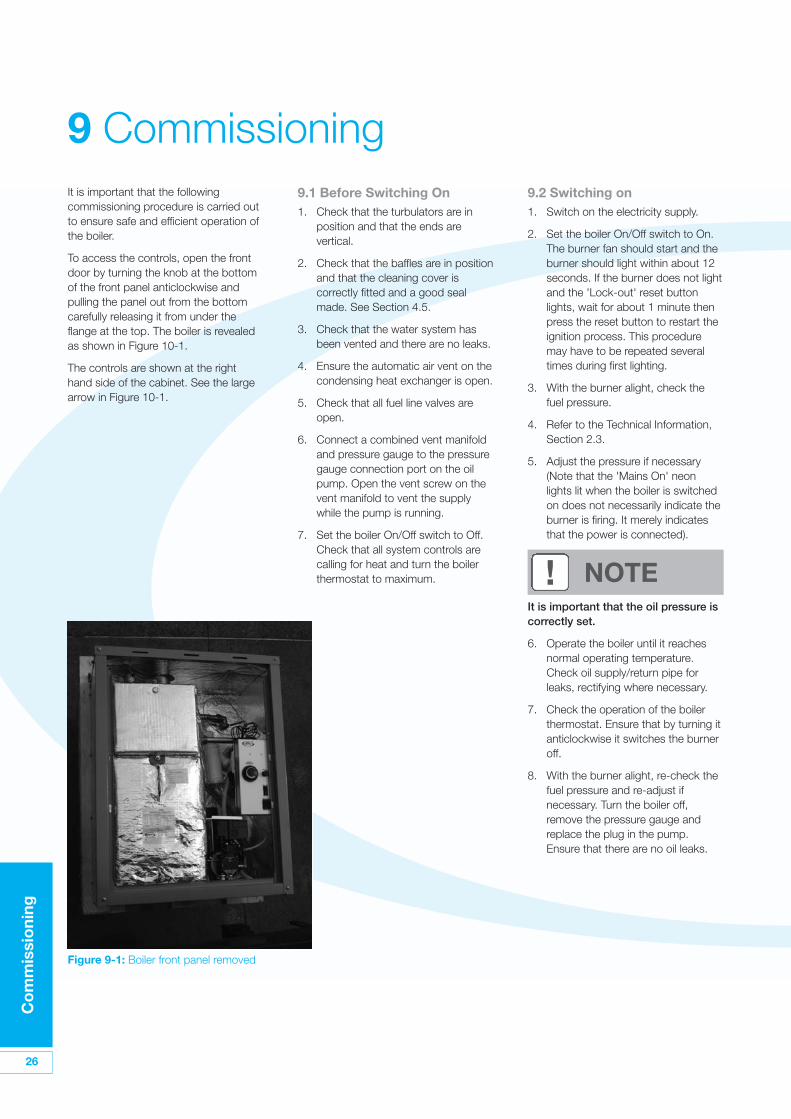
Figure 9-1: Boiler front panel removed
9.2 Switching on1. Switch on the electricity supply.
2. Set the boiler On/Off switch to On.The burner fan should start and theburner should light within about 12seconds. If the burner does not lightand the 'Lock-out' reset buttonlights, wait for about 1 minute thenpress the reset button to restart theignition process. This proceduremay have to be repeated severaltimes during first lighting.
3. With the burner alight, check thefuel pressure.
4. Refer to the Technical Information,Section 2.3.
5. Adjust the pressure if necessary(Note that the 'Mains On' neonlights lit when the boiler is switchedon does not necessarily indicate theburner is firing. It merely indicatesthat the power is connected).
9.1 Before Switching On1. Check that the turbulators are in
position and that the ends arevertical.
2. Check that the baffles are in positionand that the cleaning cover iscorrectly fitted and a good sealmade. See Section 4.5.
3. Check that the water system hasbeen vented and there are no leaks.
4. Ensure the automatic air vent on thecondensing heat exchanger is open.
5. Check that all fuel line valves areopen.
6. Connect a combined vent manifoldand pressure gauge to the pressuregauge connection port on the oilpump. Open the vent screw on thevent manifold to vent the supplywhile the pump is running.
7. Set the boiler On/Off switch to Off.Check that all system controls arecalling for heat and turn the boilerthermostat to maximum.
It is important that the followingcommissioning procedure is carried outto ensure safe and efficient operation ofthe boiler.
To access the controls, open the frontdoor by turning the knob at the bottomof the front panel anticlockwise andpulling the panel out from the bottomcarefully releasing it from under theflange at the top. The boiler is revealedas shown in Figure 10-1.
The controls are shown at the righthand side of the cabinet. See the largearrow in Figure 10-1.
! NOTEIt is important that the oil pressure iscorrectly set.
6. Operate the boiler until it reachesnormal operating temperature.Check oil supply/return pipe forleaks, rectifying where necessary.
7. Check the operation of the boilerthermostat. Ensure that by turning itanticlockwise it switches the burneroff.
8. With the burner alight, re-check thefuel pressure and re-adjust ifnecessary. Turn the boiler off,remove the pressure gauge andreplace the plug in the pump.Ensure that there are no oil leaks.
Co
mm
issi
oni
ng
27
9.3 Running the Boiler1. Relight the boiler and allow it to run
for at least 20 minutes.
2. Insert combustion probe into theend of the flue terminal to measurethe CO2 level. Do not use the boilertest point.
3. Turn the air control knob on theburner to adjust the burner airdamper (refer to Figure 3-3) asrequired. Turning the knobanti-clockwise closes the damperand increases CO2 level. Turning theknob clockwise opens the damperand reduces CO2 level.
4. Re-check the smoke number if thedamper has been moved. Under nocircumstances must the smokenumber be above 1.
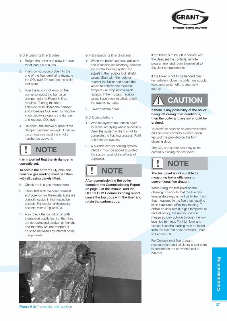
Figure 9-3: Thermostat phial position
! NOTEIt is important that the air damper iscorrectly set.
To obtain the correct CO2 level, thefinal flue gas reading must be takenwith all casing panels fitted.
5. Check the flue gas temperature.
6. Check that both the boiler overheatand boiler control thermostat bulbs arecorrectly located in their respectivepockets. For location of thermostatpockets, refer to Figure 10-3.
7. Also check the condition of boththermostat capillaries, i.e. that theyare not damaged, broken or kinked,and that they are not trapped orcrushed between any internal boilercomponents.
! NOTE! NOTE
After commissioning the boilercomplete the Commissioning Reporton page 2 of this manual and theOFTEC CD/11 commissioning report.Leave the top copy with the User andretain the carbon copy.
9.4 Balancing the System1. When the boiler has been adjusted
and is running satisfactorily, balancethe central heating system byadjusting the radiator lock shieldvalves. Start with the radiatornearest the boiler and adjust thevalves to achieve the requiredtemperature drop across eachradiator. If thermostatic radiatorvalves have been installed, checkthe system by-pass.
2. Switch off the boiler.
9.5 Completion1. With the system hot, check again
for leaks, rectifying where necessary.Drain the system while it is hot tocomplete the flushing process. Refilland vent the system.
2. A suitable central heating systeminhibitor must be added to protectthe system against the effects ofcorrosion.
If the boiler is to be left in service withthe User, set the controls, remoteprogrammer and room thermostat tothe User's requirements.
If the boiler is not to be handed overimmediately, close the boiler fuel supplyvalve and switch off the electricitysupply.
If there is any possibility of the boilerbeing left during frost conditions,then the boiler and system should bedrained.
To allow the boiler to be commissionedand serviced correctly a combustiontest point is provided on the frontcleaning door.
The CO2 and smoke test may all becarried out using this test point.
The test point is not suitable formeasuring boiler efficiency orconventional flue draught.
When using the test point on thecleaning cover note that the flue gastemperature reading will be higher thanthat measured in the flue thus resultingin an inaccurate efficiency reading. Toobtain an accurate flue gas temperatureand efficiency, the reading can bemeasured only outside through the lowlevel flue terminal. For high level andvertical flues the reading may be takenfrom the flue test point provided. Referto Section 2.3.
For Conventional flue draughtmeasurement and efficiency a test pointis provided in the conventional flueadaptor.
! CAUTION
28
Bo
iler
Ser
vici
ng
10 Boiler ServicingTo ensure efficient operation of theboiler it is recommended that it ischecked and serviced as necessary atregular intervals. The frequency ofservicing will depend upon the particularinstallation conditions and usage, but ingeneral once per year should beadequate.
Servicing and replacement of partsmust only be carried out by a suitablyqualified engineer.
7. With the fuel supply valve closed,clean/replace the filter element andclean the filter bowl.
8. Braided flexible fuel supply hoses assupplied with the boiler should bereplaced annually when the boiler isserviced. If long-life hoses havebeen installed, these should beinspected annually. If in doubtreplace the hoses. In any event,these hoses must be replaced everyfive years.
10.3 Cleaning the Boiler
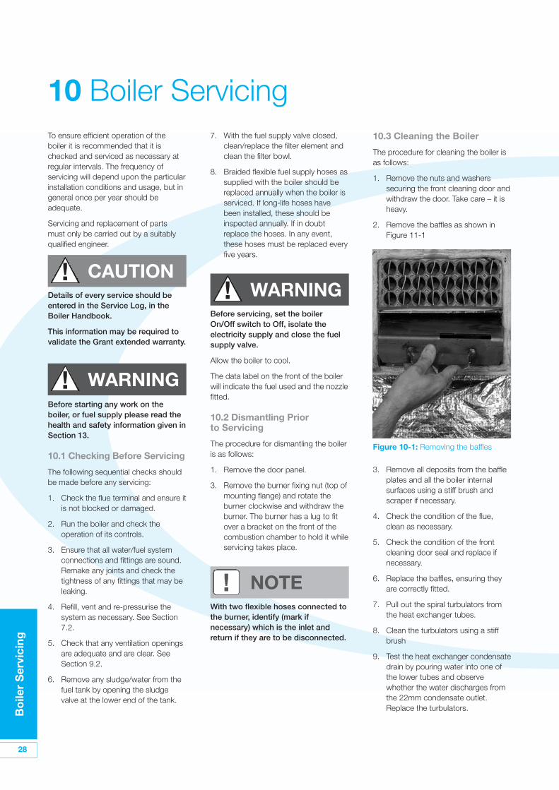
The procedure for cleaning the boiler isas follows:
1. Remove the nuts and washerssecuring the front cleaning door andwithdraw the door. Take care – it isheavy.
2. Remove the baffles as shown inFigure 11-1
3. Remove all deposits from the baffleplates and all the boiler internalsurfaces using a stiff brush andscraper if necessary.
4. Check the condition of the flue,clean as necessary.
5. Check the condition of the frontcleaning door seal and replace ifnecessary.
6. Replace the baffles, ensuring theyare correctly fitted.
7. Pull out the spiral turbulators fromthe heat exchanger tubes.
8. Clean the turbulators using a stiffbrush
9. Test the heat exchanger condensatedrain by pouring water into one ofthe lower tubes and observewhether the water discharges fromthe 22mm condensate outlet.Replace the turbulators.
Figure 10-1: Removing the baffles
! WARNING
! NOTE
! CAUTIONDetails of every service should beentered in the Service Log, in theBoiler Handbook.
This information may be required tovalidate the Grant extended warranty.
Before starting any work on theboiler, or fuel supply please read thehealth and safety information given inSection 13.
10.1 Checking Before Servicing
The following sequential checks shouldbe made before any servicing:
1. Check the flue terminal and ensure itis not blocked or damaged.
2. Run the boiler and check theoperation of its controls.
3. Ensure that all water/fuel systemconnections and fittings are sound.Remake any joints and check thetightness of any fittings that may beleaking.
4. Refill, vent and re-pressurise thesystem as necessary. See Section7.2.
5. Check that any ventilation openingsare adequate and are clear. SeeSection 9.2.
6. Remove any sludge/water from thefuel tank by opening the sludgevalve at the lower end of the tank.
Before servicing, set the boilerOn/Off switch to Off, isolate theelectricity supply and close the fuelsupply valve.
Allow the boiler to cool.
The data label on the front of the boilerwill indicate the fuel used and the nozzlefitted.
10.2 Dismantling Prior to Servicing
The procedure for dismantling the boileris as follows:
1. Remove the door panel.
3. Remove the burner fixing nut (top ofmounting flange) and rotate theburner clockwise and withdraw theburner. The burner has a lug to fitover a bracket on the front of thecombustion chamber to hold it whileservicing takes place.
With two flexible hoses connected tothe burner, identify (mark ifnecessary) which is the inlet andreturn if they are to be disconnected.
! WARNING
Bo
iler
Ser
vici
ng
29
10. Replace the front cleaning door,ensuring the seal is in goodcondition and secure it in positionwith the nuts and washerspreviously removed. Tighten to forma seal.
11. Remove the condensate trap andcheck that it is not blocked and isoperating correctly, i.e. the float is freeto move. Clean the trap and float asrequired.Refer to Section 6.8.
12. Check that the boiler condensateoutlet is unobstructed. Clean ifnecessary.
! NOTEThe condensate trap and condensateoutlet must be checked on everyservice and cleaned as necessary.
10.4 Cleaning the Burner
The procedure is:
1. Combustion head - Loosen the twoscrews securing the combustionhead and withdraw the head.
2. Clean the combustion head.
3. Inspect the ignition electrodes -Loosen the electrode clamp screwand withdraw the electrodeassembly. Wipe clean and check forany cracks in the ceramic insulation.Replace if necessary.
4. Nozzle - The nozzle should bereplaced on an annual service -Check that the nozzle size and typeare correct, refer to table in Section3.3 and boiler data label.
5. Do not attempt to clean the nozzle.
6. Remove the nozzle using a goodfitting spanner (16mm).
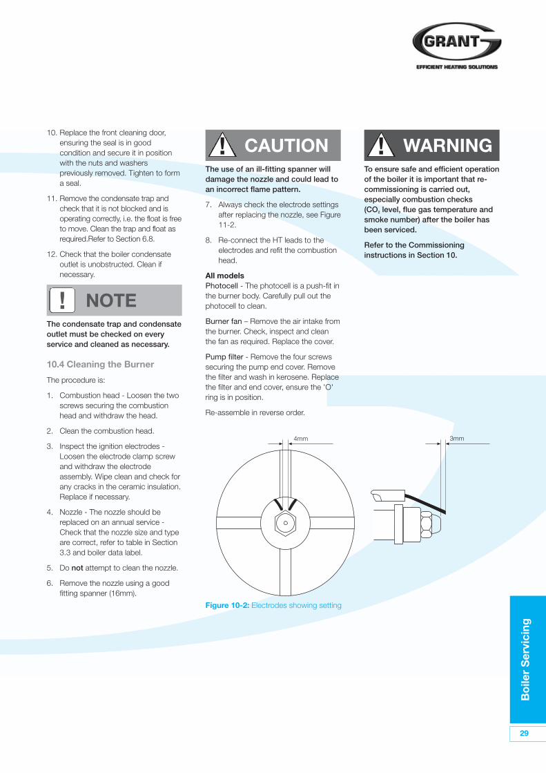
Figure 10-2: Electrodes showing setting
4mm 3mm
! CAUTIONThe use of an ill-fitting spanner willdamage the nozzle and could lead toan incorrect flame pattern.
7. Always check the electrode settingsafter replacing the nozzle, see Figure11-2.
8. Re-connect the HT leads to theelectrodes and refit the combustionhead.
All modelsPhotocell - The photocell is a push-fit inthe burner body. Carefully pull out thephotocell to clean.
Burner fan – Remove the air intake fromthe burner. Check, inspect and cleanthe fan as required. Replace the cover.
Pump filter - Remove the four screwssecuring the pump end cover. Removethe filter and wash in kerosene. Replacethe filter and end cover, ensure the 'O'ring is in position.
Re-assemble in reverse order.
To ensure safe and efficient operationof the boiler it is important that re-commissioning is carried out,especially combustion checks(CO2 level, flue gas temperature andsmoke number) after the boiler hasbeen serviced.
Refer to the Commissioninginstructions in Section 10.
! WARNING
30
Faul
t Fi
ndin
g
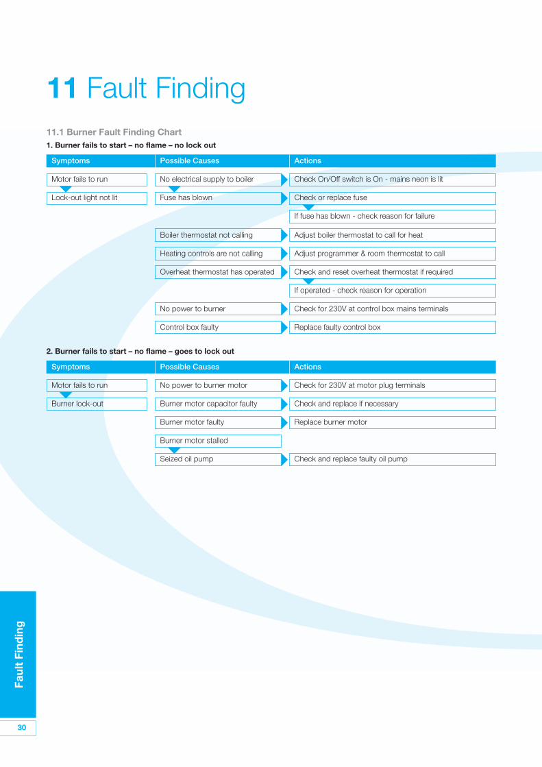
11 Fault Finding11.1 Burner Fault Finding Chart1. Burner fails to start – no flame – no lock out
Symptoms Possible Causes Actions
Motor fails to run No electrical supply to boiler Check On/Off switch is On - mains neon is lit
Lock-out light not lit Fuse has blown Check or replace fuse
If fuse has blown - check reason for failure
Boiler thermostat not calling Adjust boiler thermostat to call for heat
Heating controls are not calling Adjust programmer & room thermostat to call
Overheat thermostat has operated Check and reset overheat thermostat if required
If operated - check reason for operation
No power to burner Check for 230V at control box mains terminals
Control box faulty Replace faulty control box
2. Burner fails to start – no flame – goes to lock out
Symptoms Possible Causes Actions
Motor fails to run No power to burner motor Check for 230V at motor plug terminals
Burner lock-out Burner motor capacitor faulty Check and replace if necessary
Burner motor faulty Replace burner motor
Burner motor stalled
Seized oil pump Check and replace faulty oil pump
Faul
t Fi
ndin
g
31
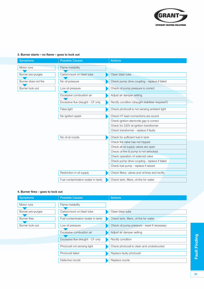
3. Burner starts – no flame – goes to lock out
Symptoms Possible Causes Actions
Motor runs Flame instability
Burner pre-purges Carbon/soot on blast tube Clean blast tube
Burner does not fire No oil pressure Check pump drive coupling - replace if failed
Burner lock-out Low oil pressure Check oil pump pressure is correct
Excessive combustion air Adjust air damper setting
Excessive flue draught - CF only Rectify condition (draught stabiliser required?)
False light Check photocell is not sensing ambient light
No ignition spark Check HT lead connections are sound
Check ignition electrode gap is correct
Check for 230V at ignition transformer
Check transformer - replace if faulty
No oil at nozzle Check for sufficient fuel in tank
Check fire valve has not tripped
Check all oil supply valves are open
Check oil line & pump is not airlocked
Check operation of solenoid valve
Check pump drive coupling - replace if failed
Check fuel pump - replace if seized
Restriction in oil supply Check filters, valves and oil lines and rectify
Fuel contamination (water in tank) Check tank, filters, oil line for water
4. Burner fires – goes to lock out
Symptoms Possible Causes Actions
Motor runs Flame instability
Burner pre-purges Carbon/soot on blast tube Clean blast tube
Burner fires Fuel contamination (water in tank) Check tank, filters, oil line for water
Burner lock-out Low oil pressure Check oil pump pressure - reset if necessary
Excessive combustion air Adjust air damper setting
Excessive flue draught - CF only Rectify condition
Photocell not sensing light Check photocell is clean and unobstructed
Photocell failed Replace faulty photocell
Defective nozzle Replace nozzle
32
Faul
t Fi
ndin
g
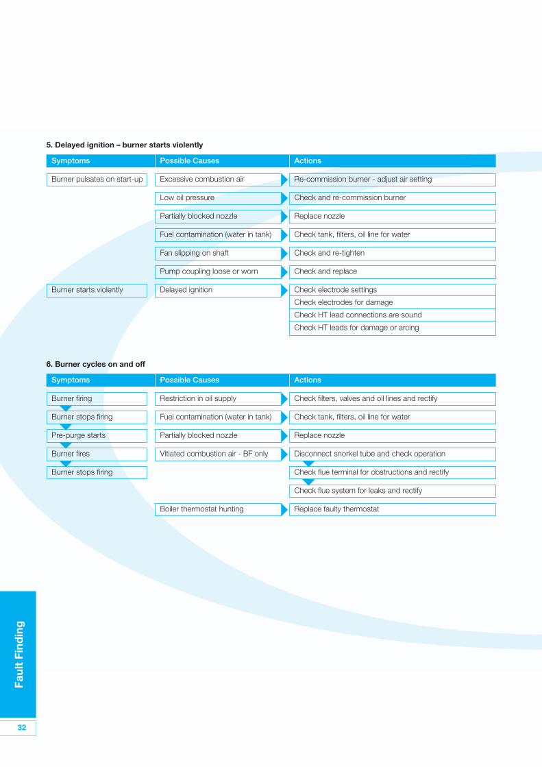
5. Delayed ignition – burner starts violently
Symptoms Possible Causes Actions
Burner pulsates on start-up Excessive combustion air Re-commission burner - adjust air setting
Low oil pressure Check and re-commission burner
Partially blocked nozzle Replace nozzle
Fuel contamination (water in tank) Check tank, filters, oil line for water
Fan slipping on shaft Check and re-tighten
Pump coupling loose or worn Check and replace
Burner starts violently Delayed ignition Check electrode settings
Check electrodes for damage
Check HT lead connections are sound
Check HT leads for damage or arcing
6. Burner cycles on and off
Symptoms Possible Causes Actions
Burner firing Restriction in oil supply Check filters, valves and oil lines and rectify
Burner stops firing Fuel contamination (water in tank) Check tank, filters, oil line for water
Pre-purge starts Partially blocked nozzle Replace nozzle
Burner fires Vitiated combustion air - BF only Disconnect snorkel tube and check operation
Burner stops firing Check flue terminal for obstructions and rectify
Check flue system for leaks and rectify
Boiler thermostat hunting Replace faulty thermostat
Faul
t Fi
ndin
g
33
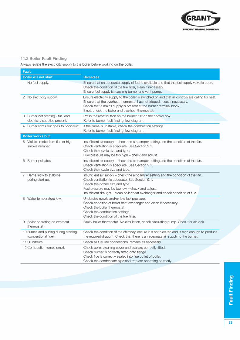
11.2 Boiler Fault FindingAlways isolate the electricity supply to the boiler before working on the boiler.
Fault
Boiler will not start: Remedies
1 No fuel supply. Ensure that an adequate supply of fuel is available and that the fuel supply valve is open.Check the condition of the fuel filter, clean if necessary. Ensure fuel supply is reaching burner and vent pump.
2 No electricity supply. Ensure electricity supply to the boiler is switched on and that all controls are calling for heat.Ensure that the overheat thermostat has not tripped, reset if necessary. Check that a mains supply is present at the burner terminal block. If not, check the boiler and overheat thermostat.
3 Burner not starting - fuel and Press the reset button on the burner if lit on the control box.electricity supplies present. Refer to burner fault finding flow diagram.
4 Burner lights but goes to ‘lock-out’. If the flame is unstable, check the combustion settings. Refer to burner fault finding flow diagram.
Boiler works but:
5 Visible smoke from flue or high Insufficient air supply – check the air damper setting and the condition of the fan.smoke number. Check ventilation is adequate. See Section 9.1.
Check the nozzle size and type. Fuel pressure may be too high – check and adjust.
6 Burner pulsates. Insufficient air supply – check the air damper setting and the condition of the fan.Check ventilation is adequate, See Section 9.1.Check the nozzle size and type.
7 Flame slow to stabilise Insufficient air supply – check the air damper setting and the condition of the fan.during start up. Check ventilation is adequate, See Section 9.1.
Check the nozzle size and type.Fuel pressure may be too low – check and adjust.Insufficient draught – clean boiler heat exchanger and check condition of flue.
8 Water temperature low. Undersize nozzle and/or low fuel pressure. Check condition of boiler heat exchanger and clean if necessary.Check the boiler thermostat.Check the combustion settings.Check the condition of the fuel filter.
9 Boiler operating on overheat Faulty boiler thermostat. No circulation, check circulating pump. Check for air lock.thermostat.
10 Fumes and puffing during starting Check the condition of the chimney, ensure it is not blocked and is high enough to produce(conventional flue). the required draught. Check that there is an adequate air supply to the burner.
11 Oil odours. Check all fuel line connections, remake as necessary.
12 Combustion fumes smell. Check boiler cleaning cover and seal are correctly fitted.Check burner is correctly fitted onto flange.Check flue is correctly sealed into flue outlet of boiler.Check the condensate pipe and trap are operating correctly.
34
Sp
are
Par
ts
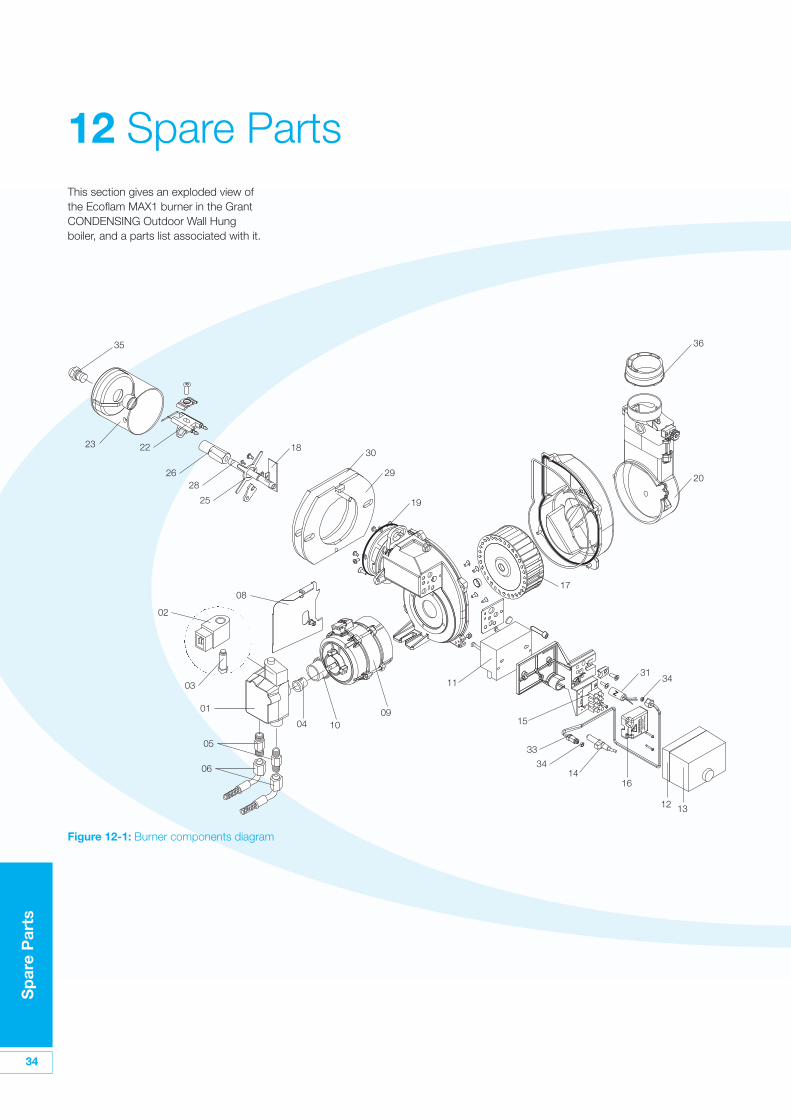
This section gives an exploded view ofthe Ecoflam MAX1 burner in the GrantCONDENSING Outdoor Wall Hungboiler, and a parts list associated with it.
12 Spare Parts
23 22
35
2628
25
02
08
01
05
06
03
04 1009
11
1416
12 13
33
34
15
18 30
29 20
36
19
3134
17
Figure 12-1: Burner components diagram

Sp
are
Par
ts
35
Key No. Description Ecoflam Part No. Grant Part No.
01 Oil Pump Danfoss BFP11 R3 P121/3 EBS01
02 Coil Danfoss V510/2 EBS02
03 Oil valve Danfoss V412/1 EBS03
04 Coupling AEG MP504 EBS04
05 Nipple TN 6X 700 BFRO1103/001 EBS05
06 Hoses NW 6X 700 S931/055 EBS06
09 Motor 75W AEG M181/12 EBS09
10 Capacitor 3µF x 75W AEG C107/9 EBS10
11 Ignition transformer Danfoss CM T130 EBS11
12 Control box base Landis A402 EBS12
13 Control box Landis LOA24 A117/1 EBS13
14 Photoresistor Landis A208/3 EBS14
15 Wiring terminal box E228 EBS15
16 Protection box BFC02046/056 EBS16
17 Fan 120 x 34 W123/2 EBS17
18 Fan scoop BFC02049/001 EBS18
19 O-ring BFG01043 EBS19
20 Cover air inlet - Wall-hung 40/55 BAA10019 EBS20
21 Cables BFE01401/3 EBS21
22 Electrodes BFE01109 EBS22
23 Burner head BFB01326/007 EBS23
25 Nozzle holder support BFC10031/001 EBS25
26 Nozzle holder BFC11017 EBS26
28 Rod BFA06429/001 EBS28
29 Flange BFF01022/001 EBS29
30 Gasket BFG02016 EBS30
31 Anti-jamming filter D.E.M S132/3 EBS31
33 Oil pipe BFT05258 EBS33
34 Pipe gasket BFG01042 EBS34
35 Nozzle - Wall-hung 12.7kW 0.35 80ºEH - M1BS27/75
Nozzle - Wall-hung 14.0kW 0.40 80ºEH - M1BS27/50
Nozzle - Wall-hung 16.5 & 18.7kW 0.50 80ºEH - M1BS27/46
Nozzle - Wall-hung 20.3kW 0.60 80ºEH - M1BS27/31
36 Ring BFC03039/4 EBS36

36
Hea
lth
and
Saf
ety
Info
rmat
ion
Under the Consumer Protection Act1987 and Section 6 of the Health &Safety at Work Act 2005, we arerequired to provide information onsubstances hazardous to health(COSHH Regulations 1988).
Adhesives, sealants and paints used inthe manufacture of the product arecured and present no known hazardswhen used in the manner for which theyare intended.
The following other materials arepresent in the product:
13.1 Insulation MaterialsMaterial Types: Ceramic fibre board,mineral wool.
Description: Rigid board, slabs, sleeves,gaskets, ropes.
Known Hazards: May cause temporaryirritation or rash to skin. High dust levelsmay irritate eyes and upper respiratorysystem.
Precautions: Avoid unnecessary orrough handling, or harsh abrasion ofboards. Normal handling and use ofmaterial should not produce high dustlevels.
Avoid inhalation, and contact with skinand eyes.
After handling always follow normalgood hygiene practices.
Protection: Use disposable gloves, facemask and eye protection.
First Aid: Eyes - If irritation occurs,wash eyes with copious amounts ofwater. If symptoms persist, seek
immediate medical advice.
Skin - If irritation occurs, wash underrunning water before washing with soapand water.
Inhalation - Remove to fresh air, drinkwater to clear throat and blow nose toremove dust/fibres.
Ingestion - Drink plenty of water.
Material Types: Silicone elastomer.
Description: Sealant and adhesive.
Known Hazards: Irritation to eyes.
Precautions: Avoid inhalation of vapour,contact with eyes and prolonged orrepeated contact with skin.
After handling always follow normalgood hygiene practices.
Protection: Use eye protection. Rubberor plastic gloves should be worn whererepeated contact occurs and a facemask worn when working in confinedspaces.
First Aid: Eyes - Flush eyes with waterfor 15 minutes. Seek immediate medicalattention.
Skin - Wipe off and wash with soap andwater.
Inhalation - Remove to fresh air.
13.2 Kerosene and Gas OilFuels (mineral oils)Known Hazards: The effect of mineraloils on the skin vary according to theduration of exposure and the type of oil.
The lighter fractions remove theprotective grease naturally present onthe skin, leaving it dry, liable
to crack and more prone to damage bycuts, abrasions and irritant chemicals.
Skin rashes (Oil acne) most often onarms, but also on any part of the bodyin contact with oil or oily clothing.
Contact with fuel oils can causedermatitis.
Precautions: Avoid as far as possibleany skin contact with mineral oil or withclothing contaminated with mineral oil.
The use of a lanolin-based barrier creamis recommended, in conjunction withregular washing with
soap and rinsing with water to ensure alloil is removed from the skin.
Take care to prevent clothing, especiallyunderwear, from becomingcontaminated with oil.
Do not put oily rags or tools in pockets,especially trouser pockets.
Have first-aid treatment at once for aninjury, however slight.
Do not inhale any vapours from mineraloils.
13 Health and Safety Information
EC
Dec
lara
tio
no
f C
onf
orm
ity
37
We declare that the Grant Condensingrange of Oil Boilers equipped withEcoflam MAX1 burners approved toEN 267: 1999 satisfy the requirementsof the following European Directives:-
1. 89/336/EEC - ElectromagneticCompatibility Directive.
Referred to the generic standards EN55014: 1993, EN 50082: 1: 1992.
2. 73/23/EEC - Electrical EquipmentSafety Regulations Directive.
Referred to the generic standardNO: 3260: The Electrical Equipment(Safety) Regulations: 1994.
3. 92/42/EEC - Hot Water BoilerEfficiency Directive.
Referred to the generic standardThe Boiler (Efficiency) (Amendment)Regulations 1994 (SI 1994/3083).
In non-EU CountriesIn non-EU countries, dispose ofelectrical and electronic equipment andall surplus packaging in accordancewith national and regional regulations.
Complies with EC Low voltageElectromagnetic compatibility and Boiler efficiency Directives.
89/336/EEC73/23/EEC92/42/EEC
In EU CountriesThe following information is provided toenable regulatory compliance with theEuropean Union (EU) directivesidentified and any amendments made tothese directives when using electrical orelectronic equipment in EU countries.
Disposal of Electrical andElectronic EquipmentEuropean Union (EU) Directive2002/96/EC Waste Electrical andElectronic Equipment (WEEE)
Do not dispose of electrical or electronicequipment in landfill sites. In the EU, it isthe individual recipient’s responsibility toensure that discarded electrical orelectronic materials are collected andrecycled according to the requirementsof EU environmental law.
Disposal of Surplus PackagingEuropean Parliament and CouncilDirective 94/62/EC Packaging andPackaging Waste
Do not dispose of surplus packaging inlandfill sites. In the EU, it is the individualrecipient’s responsibility to ensure thatpackaging materials are collected andrecycled according to the requirementsof EU environmental law.
14 EC Declaration of Conformity

User Instructio
ns
7
6
User Instructio
ns
Overheat ThermostatYour boiler is fitted with a safety overheatthermostat which will automaticallyswitch off the boiler in the case of acontrol malfunction causing overheating.If your boiler goes off and you try to lightit but nothing happens, and the LockoutReset button on the burner has nottriggered, the overheat thermostat hasprobably operated. The boiler will notlight until the thermostat is reset. Toreset, unscrew the small plastic capmarked Reset (see Figure 3), press thebutton then replace the cap.
If this condition continually repeats,contact your Service engineer.
Remote Programmer Refer to the instructions supplied withyour particular system programmer.
VentilationDo not attempt to 'box in' the boiler orbuild a compartment around it beforeconsulting you Installer.
Do notplace any combustible materialaround or on the boiler or flue pipe.
Flue TerminalThe flue terminal must notbeobstructed or damaged.
In severe conditions check that theterminal does not become blocked bysnow.
Frost ProtectionYour Installer may have fitted a frostthermostat. If not, and you are likely tobe away for a short time, leave theboiler on with the boiler thermostat setat a low setting. For longer periods theboiler and system should be drained.
The boiler has a built in frost thermostatfactory set to 5°C.
Contact your Service engineer fordraining and filling the system.
Cleaning and ServicingLightly wipe over the case with a dampcloth and a little detergent. Do notuseabrasive pads or cleaners.
You must have your boiler serviced atleast once a year to ensure safe andefficient operation. Contact your Serviceengineer for further details.
Failure of Electricity SupplyIf the electricity supply fails, the boiler willnot operate. It should relightautomatically when the supply isrestored.
If a remote programmer is connected, itmay retain the time settings for sometime and may not have to be reset to thecorrect time of day when the supply isrestored. Refer to the instructionssupplied with your programmer forfurther details.. It is recommended thatyou check the time settings after apower failure has occurred.
Electricity SupplyThe boiler requires a 230/240 V ~ 50 Hzsupply. It must be protected by a5 Amp fuse.
The electricity connections to theboiler must be earthed.
!WARNING
For Condensing modules werecommend that a combinedantifreeze and corrosion inhibitor beused in the primary water system.
!NOTE
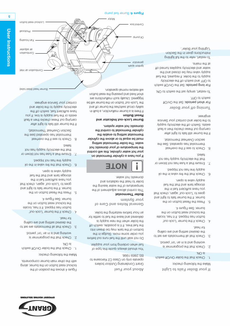
User Instructio
ns
5
If your Boiler Fails to LightMake the following checks:
1.Check that the boiler On/Off switchis ON.
2.Check that the programmer isworking and is in an 'on' period.
3.Check that all thermostats are set tothe desired setting and are callingfor heat.
4.Check if the burner 'Lock-out'button has tripped. If it has, locatethe lockout reset button on theburner. See Figure 4.
5.Press the Reset button on theburner. If the burner fails to light andgoes to 'Lock-out' again, check thatyou have sufficient fuel in thestorage tank and that the fuelsupply valve is open.
6.Check that the fire valve in the oilsupply line has not tripped.
7.Ensure that a fuse has not blown orthat the electricity supply has notfailed.
8.Check to see if the overheatthermostat has operated. See thesection Overheat thermostat.
If the burner still fails to light aftercarrying out these checks then a faultexists. Switch off the electricity supplyto the boiler and contact your Serviceengineer.
Turning off your BoilerFor short periods:Set the On/Offswitch to OFF.
To restart, simply set the switch to ON.
For long periods:Set the On/Off switchto OFF and switch off the electricitysupply to the boiler. If required, the fuelsupply valve may be closed and thewater and electricity supplies turned offat the mains.
To restart, refer to the full lightinginstructions given in the Section‘Lighting your Boiler’.
About your FuelGrant Condensing Outdoor boilersoperate only on Class C2 Kerosene toBS 2869:1998.
You should always quote this type offuel when ordering from your supplier.
Do not wait until the fuel runs out beforeyou order some more. Sludge in thebottom of the tank may be drawn intothe fuel lines. If it is possible, switch offthe boiler when the new supply isdelivered and leave the fuel to settle foran hour before restarting the boiler.
General Notes and Care ofyour SystemBoiler ThermostatThis control allows adjustment of thetemperature of the water leaving theboiler to heat the radiators anddomestic hot water.
Figure 4:Burner fuel pump
If you have a cylinder thermostat onyour hot water cylinder, this will controlthe temperature of your domestic hotwater. The boiler thermostat settingmust be equal to or above the cylinderthermostat setting to enable thecylinder thermostat to control thedomestic hot water system.
Burner Lock-out Indicator andReset ButtonIf there is a burner malfunction, a built-insafety circuit switches the burner off andthe 'Lock-out' button on the burner will betriggered. Usually such malfunctions areshort lived and pressing the reset buttonwill restore normal operation.
!NOTE
Figure 4 shows the position of thelockout reset button on the burner, alongwith the other main burner components.
Make the following checks:
1.Check that the boiler On/Off switchis ON.
2.Check that the programmer isworking and is in an 'on' period.
3.Check that all thermostats are set tothe desired setting and are callingfor heat.
4.Check if the burner 'Lock-out'button has tripped. If it has, locatethe lockout reset button on theburner. See Figure 4.
5.Press the Reset button on theburner. If the burner fails to light andgoes to 'Lock-out' again, check thatyou have sufficient fuel in thestorage tank and that the fuelsupply valve is open.
6.Check that the fire valve in the oilsupply line has not tripped.
7.Ensure that a fuse has not blown orthat the electricity supply has notfailed.
8.Check to see if the overheatthermostat has operated (see theSection Overheat Thermostat).
If the burner still fails to light aftercarrying out these checks then a faultexists or the fuel supply is low. If youhave sufficient fuel, switch off theelectricity supply to the boiler andcontact your Service engineer.
Burner head (blast tube)
Combustion air inlet
Combustionair adjuster
Lockout reset buttonMotor
Control box
Oil pump
Ignition sparkgenerator
Photocell
Fan housing
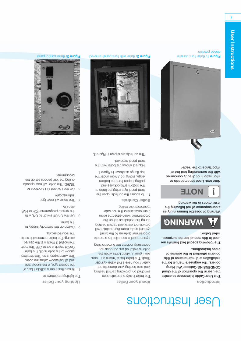
Lighting your BoilerThe lighting procedure is:
1.Ensure that there is sufficient fuel, ofthe correct type, in the supply tankand all fuel supply valves are open.The water supply is on. The electricitysupply to the boiler is off. The boilerOn/Off switch is set to OFF. The roomthermostat (if fitted) is at the desiredsetting. The boiler thermostat is set tothe required setting.
2.Switch on the electricity supply tothe boiler.
3.Set the On/Off switch to ON, withthe remote programmer (CH or HW)also ON.
4.The boiler will now lightautomatically.
5.Set the HW and CH functions toTIMED. The boiler will now operateduring the 'on' periods set on theprogrammer.
4
User Instructio
ns
IntroductionThis User Guide is intended to assistthe user in the operation of the GrantCONDENSING Outdoor Wall Hungboilers. The engineers manual for theinstallation and maintenance of thisboiler is attached to the reverse ofthese instructions.
The following special text formats areused in this manual for the purposeslisted below:
Warning of possible human injury asa consequence of not following theinstructions in the warning.
Note text. Used for emphasis orinformation not directly concernedwith the surrounding text but ofimportance to the reader.
Figure 1:Boiler front panel inclosed position
Figure 2:Boiler with front panel removedFigure 3:Boiler control panel
User Instructions
!WARNING
!NOTE
About your BoilerThe boiler is fully automatic onceswitched on, providing central heating(and also heating your domestic hotwater if you have a hot water cylinderfitted). The boiler has a 'mains on' neon,see Figure 3, which lights when theboiler is switched on, but does notnecessarily indicate the burner is firing.
If your model is controlled by a remoteprogrammer (external to the Grantsystem) and a room thermostat, it willprovide hot water and central heatingduring the periods as set on theprogrammer, when either the roomthermostat and/or the hot waterthermostat are calling.
Boiler Controls1.To access the controls, open the
front panel by turning the knob atthe bottom anticlockwise andpulling it open from the bottomedge, sliding it out from under thetop flange as shown in Figure 1.
Figure 2 shows the boiler with thefront panel removed.
The controls are shown in Figure 3.
Contents
Co
ntents
3
Overheat Thermostat6
Remote Programmer6
Ventilation6
Flue Terminal6
Frost Protection6
Cleaning and Servicing6
Failure of Electricity Supply6
Electricity Supply6
Introduction4
About your Boiler4
Boiler Controls4
Lighting your Boiler4
If your Boiler Fails to Light5
Turning off your Boiler5
About your Fuel5
General Notes and Careof your System5
Boiler Thermostat5
Burner Lock-out Indicator andReset Button5

2
Service Lo
g
For use with Kerosene only.
After installing the boiler leave theseinstructions with the User.
Service LogIt is recommended that the boiler shouldbe regularly serviced, at least once ayear, and the details entered in theBoiler Handbook by the serviceengineer.
GRANT ENGINEERING (IRELAND) LIMITEDCrinkle, Birr, Co. Offaly, IrelandTel: (057) 91 20089 Fax: (057) 91 21060 Email: [email protected] www.grantengineering.ie
This manual is accurate at the date of printing but will be superseded and should be disregarded if specifications and/orappearances are changed in the interests of continued product improvement.All good sold are subject to our official Conditions of Sale, a copy of which may be obtained on application.© Grant Engineering (Ireland) Limited 2008. No part of this manual may be reproduced by any means without prior writtenconsent.
Grant Condensing Outdoor Wall Hung Condensing Oil Boiler Range
User Instructions
Part No. DOC 85. Rev 0. November 2008