OTC-29278-MS The Subsea Sand Management Challenge – What ...
16
OTC-29278-MS The Subsea Sand Management Challenge – What to Do with the Sand? Charles H. Rawlins and John C. Ditria, eProcess Technologies Copyright 2019, Offshore Technology Conference This paper was prepared for presentation at the Offshore Technology Conference held in Houston, Texas, USA, 6 – 9 May 2019. This paper was selected for presentation by an OTC program committee following review of information contained in an abstract submitted by the author(s). Contents of the paper have not been reviewed by the Offshore Technology Conference and are subject to correction by the author(s). The material does not necessarily reflect any position of the Offshore Technology Conference, its officers, or members. Electronic reproduction, distribution, or storage of any part of this paper without the written consent of the Offshore Technology Conference is prohibited. Permission to reproduce in print is restricted to an abstract of not more than 300 words; illustrations may not be copied. The abstract must contain conspicuous acknowledgment of OTC copyright. Abstract Sand is a limiting design factor for facilities in terms of operability, throughput, and maintenance. These effects are more critical when dealing with subsea processing due to the equipment access and risk exposure. Technologies for erosion management, sand separation, and solids disposal are well proven for surface facilities. For example, the wellhead desander, located upstream of the choke, effectively separates sand from the multiphase well flow and can be marinized for subsea use. However, the crucial question is "What to do with the sand?" This white paper provides a focal point for the discussion on sand management in subsea processing. The broad categories for dealing with sand include neutralization of the effects, improvements in conventional design, and separation with disposal. These categories have been analyzed based on the conventional design, treatment of the solids, and removal of the solids. More than thirty discrete treatment routes were surveyed, including conventional production limits, flow path modification, chemical treatment, sand cleaning, mechanical attrition, slurry fracture injection, and accretion disposal. Many of these technologies have analogues in other particulate processing industries that can be adapted to upstream oil and gas production. This work is part of ongoing research in Facilities Sand Management with the goal of improving the hydrocarbon recovery through inclusionary sand production. Introduction A watershed Facilities Sand Management workshop was held on April 10, 2002. This SPE Gulf Coast Section event brought together more than 150 people to specifically discuss the effects of sand on all aspects of production and facilities in the upstream oil and gas industry. In analyzing the feedback from the attendees, the top five technology needs for the industry were collated. These were (in ascending order of importance) instrumentation, more case studies/examples, sand cleaning, integrated subsurface/surface approach, and seabed separation and disposal. The removal and handling of sand on the seabed was the number one technology interest identified at that time. This was near the start of the movement by operators to push more of the production into deeper waters – and they identified that handling solids in subsea processing would be an impediment to reliable, cost-effective operation. Now that subsea production is deployed in all major deepwater producing regions, has subsea sand management been properly addressed, if at all? Some steps have been taken, but overall, the main approach has been to (attempt to) prevent sand from appearing at the subsea facilities or hope that sand never arrives. The costs of foolproof deepwater well completions, both in time and finances, can be prohibitive
Transcript of OTC-29278-MS The Subsea Sand Management Challenge – What ...

OTC-29278-MS
The Subsea Sand Management Challenge – What to Do with the Sand?
Charles H. Rawlins and John C. Ditria, eProcess Technologies
Copyright 2019, Offshore Technology Conference
This paper was prepared for presentation at the Offshore Technology Conference held in Houston, Texas, USA, 6 – 9 May 2019.
This paper was selected for presentation by an OTC program committee following review of information contained in an abstract submitted by the author(s). Contents ofthe paper have not been reviewed by the Offshore Technology Conference and are subject to correction by the author(s). The material does not necessarily reflect anyposition of the Offshore Technology Conference, its officers, or members. Electronic reproduction, distribution, or storage of any part of this paper without the writtenconsent of the Offshore Technology Conference is prohibited. Permission to reproduce in print is restricted to an abstract of not more than 300 words; illustrations maynot be copied. The abstract must contain conspicuous acknowledgment of OTC copyright.
AbstractSand is a limiting design factor for facilities in terms of operability, throughput, and maintenance. Theseeffects are more critical when dealing with subsea processing due to the equipment access and risk exposure.Technologies for erosion management, sand separation, and solids disposal are well proven for surfacefacilities. For example, the wellhead desander, located upstream of the choke, effectively separates sandfrom the multiphase well flow and can be marinized for subsea use. However, the crucial question is "Whatto do with the sand?" This white paper provides a focal point for the discussion on sand managementin subsea processing. The broad categories for dealing with sand include neutralization of the effects,improvements in conventional design, and separation with disposal. These categories have been analyzedbased on the conventional design, treatment of the solids, and removal of the solids. More than thirty discretetreatment routes were surveyed, including conventional production limits, flow path modification, chemicaltreatment, sand cleaning, mechanical attrition, slurry fracture injection, and accretion disposal. Many ofthese technologies have analogues in other particulate processing industries that can be adapted to upstreamoil and gas production. This work is part of ongoing research in Facilities Sand Management with the goalof improving the hydrocarbon recovery through inclusionary sand production.
IntroductionA watershed Facilities Sand Management workshop was held on April 10, 2002. This SPE Gulf CoastSection event brought together more than 150 people to specifically discuss the effects of sand on allaspects of production and facilities in the upstream oil and gas industry. In analyzing the feedback fromthe attendees, the top five technology needs for the industry were collated. These were (in ascending orderof importance) instrumentation, more case studies/examples, sand cleaning, integrated subsurface/surfaceapproach, and seabed separation and disposal. The removal and handling of sand on the seabed was thenumber one technology interest identified at that time. This was near the start of the movement by operatorsto push more of the production into deeper waters – and they identified that handling solids in subseaprocessing would be an impediment to reliable, cost-effective operation.
Now that subsea production is deployed in all major deepwater producing regions, has subsea sandmanagement been properly addressed, if at all? Some steps have been taken, but overall, the main approachhas been to (attempt to) prevent sand from appearing at the subsea facilities or hope that sand neverarrives. The costs of foolproof deepwater well completions, both in time and finances, can be prohibitive

2 OTC-29278-MS
to achieving economic performance; thus, the option of handling sand in the facilities must be consideredduring the design phase of these fields. Ongoing research in Facilities Sand Management – which hasthe stated goal of improving hydrocarbon recovery through inclusionary sand production – includes thehandling of sand in subsea production.
This current work will (Rawlins 2014):
• Identify the reasons and motivation to research subsea facilities sand management
• Provide a subsea processing discussion focal point focused on the question "What to do with thesand?"
• Identify and analyze the existing conventional, unconventional, and unique sand handling optionsto reveal technology gaps
• Research methods that include neutralizing the effects of sand, improving conventional design,and sand separation with disposal
• Investigate technology analogues from other industries that may be applied to subsea use
Surface Sand Management – ReduxAll oil and gas wells produce sand; therefore, all production facilities must be capable of managing sandin the flow streams. When sand control is not economical or technically feasible or when controls fail, thesurface facilities (offshore or onshore) must manage the produced sand. Surface sand handling is termedFacilities Sand Management (FSM). Sand coproduction, which requires FSM technology, is shown toincrease hydrocarbon recovery (Rawlins 2017). This approach completes the well without a completionstring – either barefoot or open-hole with large slots. Sand is produced with hydrocarbons to increase thereservoir interface area, decrease skin, and improve inflow. The sand must be separated and handled in thesurface facilities without interfering with the equipment uptime.
The technologies for surface FSM are fully mature and are applied at one of the four nodes of sandseparation in the production system, as shown in Figure 1.
Figure 1—The four nodes of sand separation showing the locations in the process system.
Node 1: Upstream of the choke is the multiphase (wellhead) desander. This is the first, and the highest-pressure location where sand can be removed. The separation of sand with a wellhead desander (WHD)protects the choke, flow lines, separator, and produced water treating equipment (Rawlins 2017). Thisapplication has been in use for more than 20 years.
Node 2: The wellstream desander (WSD) operates in a similar way as the WHD but is mechanicallypackaged for multiphase flow between the choke and the separator. The WSD is installed on a manifold

OTC-29278-MS 3
or near the inlet to the separator, and it may be used to process multiple wells. This application has beenin use for more than 15 years.
Node 3: Solids are separated within the production separator, but on-line removal requires a jetting system(Rawlins 2016). Here, the separator and produced water system are not protected from sand, but sand ishandled without shutting down the facility. This application has been in use for more than 40 years.
Node 4: The final location where sand is removed from the produced water stream using a standard(liquid) desander. This technology protects the oil removal equipment (i.e., deoilers and flotation cells),injection equipment, and the disposal reservoir. This application has been in use for more than 50 years.
Subsea sand management is a specific case of Facilities Sand Management. The same principles andpractices are applied, but with a focus on the unique attributes of subsea processing. Facilities SandManagement handles sand and solids in any facilities equipment with a degree of skill. This is not a wastestream treatment exercise but a critical facilities flow assurance issue. The objective of FSM is to increaseor maximize the hydrocarbon production while reducing or minimizing the operating costs (Rawlins 2013).
Subsea Sand Management
Produced Solids in Subsea ProcessingThe produced solids are defined as inorganic, insoluble, particulate material that accompanies well fluidsto the surface (Rawlins and Hewett 2007). These solids originate from natural or artificial sources. Naturalsolids are indigenous reservoir materials that are produced in low, steady-state continuous production untila failure mode occurs (i.e., water breakthrough or completion failure), which results in an unplanned highconcentration erratic production (e.g., slugging) event. Artificial solids are introduced from external sourcesas a planned event – these include frac sand, proppant, corrosion products, etc.
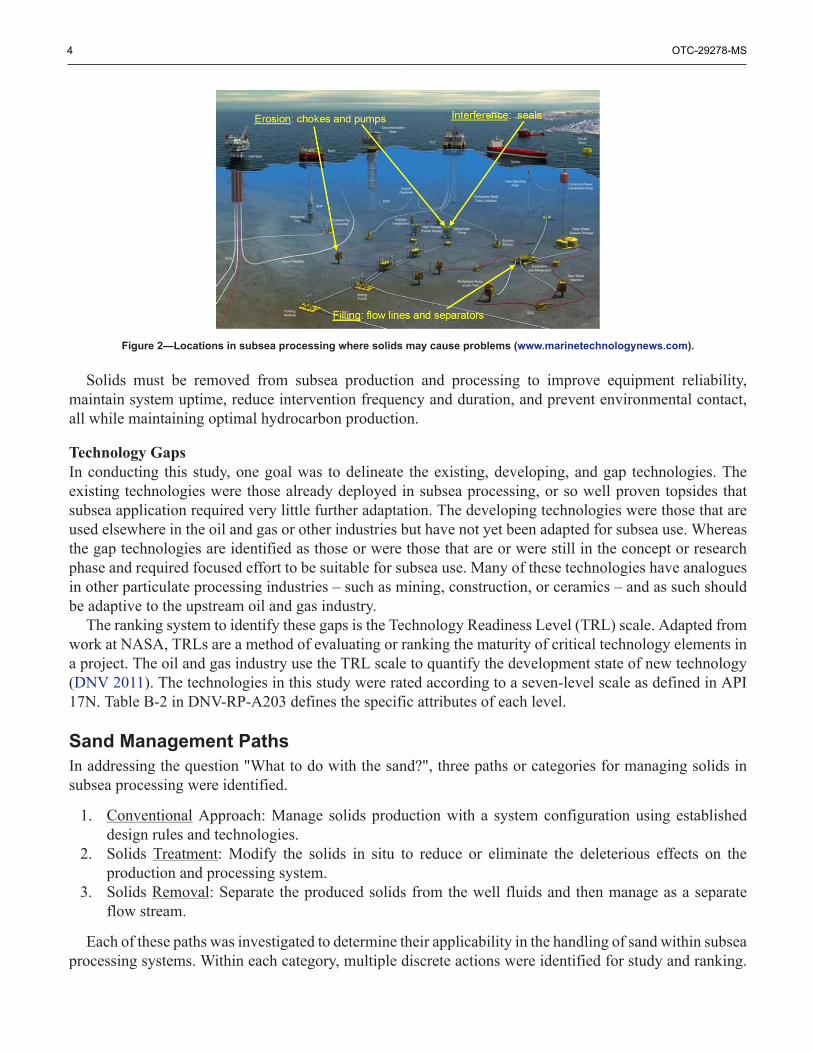
The four main issues caused by solids in production facilities – whether surface or subsea – are erosion,filling, interference, and oil-in-water content (Rawlins 2014). The specific issues that may occur in subseaprocessing equipment are illustrated in Figure 2. Erosive failure can occur in high-velocity flow regions,including the choke and control valves, pump and compressor rotors, short jumper flow lines that connectthe wellhead to the processing equipment, or long tie-back flow lines that connect the processing system tothe surface production facility (Shirazi et al 2010). Filling with solids occurs in low-velocity regions, suchas those found in the gravity separator vessels, pipe expansions, or oversized flow lines. Long tie-backswill experience reduced flow from settled solids, and gravity-based production separators will likewiseexperience a degradation of the performance or an imposed reduction in the production rate (Eriksson andKirkedam 2004). Interference occurs when the solid particles prevent a range of motion or movement offluid flow within components. Examples include the pump seals and rotor clearances, valve movement, andinstrument reading. An increased oil-in-water concentration is a concern when treating produced water forlocal discharge; however, local (subsea) discharge may never be allowed in subsea processing and is notcurrently investigated.
4 OTC-29278-MS
Figure 2—Locations in subsea processing where solids may cause problems (www.marinetechnologynews.com).
Solids must be removed from subsea production and processing to improve equipment reliability,maintain system uptime, reduce intervention frequency and duration, and prevent environmental contact,all while maintaining optimal hydrocarbon production.
Technology GapsIn conducting this study, one goal was to delineate the existing, developing, and gap technologies. Theexisting technologies were those already deployed in subsea processing, or so well proven topsides thatsubsea application required very little further adaptation. The developing technologies were those that areused elsewhere in the oil and gas or other industries but have not yet been adapted for subsea use. Whereasthe gap technologies are identified as those or were those that are or were still in the concept or researchphase and required focused effort to be suitable for subsea use. Many of these technologies have analoguesin other particulate processing industries – such as mining, construction, or ceramics – and as such shouldbe adaptive to the upstream oil and gas industry.
The ranking system to identify these gaps is the Technology Readiness Level (TRL) scale. Adapted fromwork at NASA, TRLs are a method of evaluating or ranking the maturity of critical technology elements ina project. The oil and gas industry use the TRL scale to quantify the development state of new technology(DNV 2011). The technologies in this study were rated according to a seven-level scale as defined in API17N. Table B-2 in DNV-RP-A203 defines the specific attributes of each level.
Sand Management PathsIn addressing the question "What to do with the sand?", three paths or categories for managing solids insubsea processing were identified.
1. Conventional Approach: Manage solids production with a system configuration using establisheddesign rules and technologies.
2. Solids Treatment: Modify the solids in situ to reduce or eliminate the deleterious effects on theproduction and processing system.
3. Solids Removal: Separate the produced solids from the well fluids and then manage as a separateflow stream.
Each of these paths was investigated to determine their applicability in the handling of sand within subseaprocessing systems. Within each category, multiple discrete actions were identified for study and ranking.

OTC-29278-MS 5
More than thirty discrete actions were categorized as shown in Figure 3. A description of each action withinits category is listed in the following sections.
Figure 3—Sand management paths and potential actions in subsea processing.
Conventional ApproachThe first path, entitled "Conventional Approach", manages solids production or configures the processingsystem using established rules or technologies. Seven actions within this category were identified as follows.
C-1: Downhole Completion. A completion includes a hardware barrier at the wellbore-reservoirinterface that permits oil and gas production while preventing solids from flowing with the fluids.Over-completion prevents full hydrocarbon flow, and under-completion permits sand production(Rawlins 2017). Completion hardware has a finite operating life, with replacement required uponfailure.C-2: Maximum Sand Free Production Rate. This is a production methodology that restricts thehydrocarbon flow to a limit that prevents solids from flowing into or up the wellbore to the surface.The maximum sand free rate is therefore the limit to the hydrocarbon production. Step-changes inproduction (e.g., water breakthrough) require changes in the choke setting. Over-control reduceshydrocarbon recovery, while under-control allows sand to the facility.C-3: Manage Pipe Velocity. The production flow line, either the jumper or tie-back, is sized to preventexcessive erosion (decrease the velocity) or solids settling (increase the velocity), whichever is themain concern. The resulting pipe diameter is appropriate for a specific range of flow rates only. Asthe production rate changes or wells are added/removed to/from the processing system, the velocityregime will change; however, the flow line cannot be changed in situ.C-4: Erosion Resistant Flow Line. To prevent solids from settling in the flow lines, a small diameterpipe is used to maintain the carrying velocity at all projected well conditions. The result may be thatthe flow line now experiences erosion from the particles. To prevent excessive wear on the flow line,

6 OTC-29278-MS
either a thicker pipe wall or wear-resistant pipe material is selected. The flow line may have a highercost due to the increased weight or selected material.C-5: Solids Pass-Through. This design paradigm applies to the subsea processing facility –specifically the gravity-based production separator. The velocity or flow path in the separator vesselis operated in a manner to keep the solids mobile and prevent settling. The solids pass through thevessel and are carried to the liquid outlet. The primary operation of the separator, two- or three-phaseprocessing, must be balanced with the resulting higher velocities.C-6: Erosion Management. This design paradigm also pertains to the subsea processing facility – inthis case, the equipment may experience erosion. Either the flow path is modified (e.g., the velocityreduced) or materials are appropriately selected (e.g., thicker or wear-resistant material) to minimizeerosion in that component. An example would be the choke valve plug and cage. The choke may beoversized to have lower velocity, or the cage be made thicker or of highly erosion-resistant material.The resulting choke may have a more limited operating range and/or a higher cost.C-7: Leave Sand in Place (Periodic Maintenance). A common approach in dry surface facilities withlow concentrations of sand is to allow the sand to settle and collect it in the production separator.Periodic or scheduled maintenance intervention removes the collected solids – either by shut-downand shovel or vacuum removal. While human intervention under subsea conditions is unlikely, theseparator could be brought to the surface for maintenance or a subsea vacuum system employedto remove the sand. This is a costly approach with regards to production downtime and equipmentaccess.
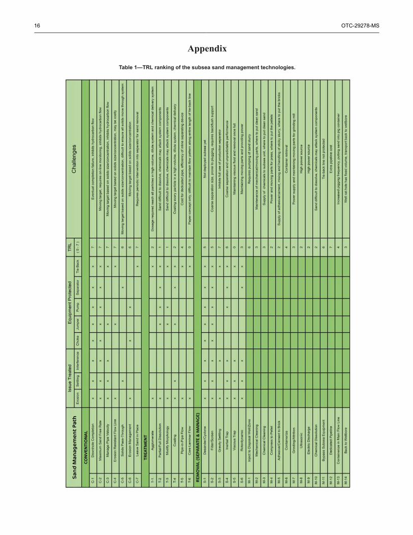
An evaluation of the conventional technologies C-1 to C-7 is provided in Table I in the Appendix. Thistable lists each action or approach, the issue treated (i.e., eliminating erosion, settling, or interference),the equipment protected (only major items shown), and the TRL. Additionally, specific challenges to thedeployment of that action are listed. For example, downhole completion (C-1) can solve all solids issues(i.e., if used properly, it prevents sand from coming to the surface), and its location (downhole) protects allsubsea processing equipment. The completions have a TRL of 7 – as they are widely deployed in all typesof fields around the world. However, two challenges with these completions are (1) that they eventuallyfail and need replacement, with the failure leading to the in-rush of sand and the replacement in deepwaterbeing costly, and (2) the completions inhibit maximum hydrocarbon recovery from the well.
All the technologies under the conventional path have a TRL at a level of 6 or 7, which is part of whatmakes them conventional. There are challenges to each of these actions. Actions C-2 through C-6 are alla moving target based on the expected solids size and concentration – as these parameters deviate fromthe design, which occurs during water breakthrough or commingling of new wells, the effectiveness ofthese actions may deteriorate. Actions C-2 and C-3 may inhibit maximum hydrocarbon recovery due tothe limited production rate. Action C-7 is easy to implement, but access to the separator for sand removalprohibits its effectiveness.
Solids TreatmentIn this path, the particulate solids are treated within the existing flow path to ameliorate the detrimentaleffects. The solids are not separated and then treated, but rather treated in situ. The treatment actions includechemical additions to modify the particle properties, so they cause less damage or change the flow pathto segment the solids from a particular section of the processing system while still allowing them to flow.Most of these actions are at the concept or R&D phase. They are listed as gap technologies that, if fullydeveloped, could provide a great advantage to production systems. These six action items are a target fordevelopment work.

OTC-29278-MS 7
T-1: Agglomerate. A chemical is added to gather the individual particles and adhere them together toform large/heavy agglomerates. These agglomerates, or clumps, settle to the bottom of the flow lineand are swept out during a pigging run. Flocculant chemicals are widely used in the water treatmentindustries for similar effects.T-2: Partial/Full Dissolution. A chemical is added to either partially or fully dissolve the solidparticles. Full dissolution may be overkill for the design, but partial dissolution is achievable. Thegoal is to reduce the particle diameter below a critical size, which then has a negligible erosive effect.Published work on erosion in pipe elbows shows a steep drop-off in the penetration rate below acritical particle size (McLaury et al. 1997). An example is shown in Figure 7 in this reference, whichshows several orders of magnitude decreases in the penetration rate for sand with a particle size below100 microns in water and of 20 microns in methane. Possible chemicals include NaOH or organicacids.T-3: Modify Size/Morphology. A chemical is added to remove the sharp, angular edges of the sandparticles and impart a smoother morphology. Improving the roundness and removing the angularcorners is shown to greatly reduce the erosive potential of sand particles. A sand sharpness factor isincluded in published erosion models (McLaury and Shirazi 1999). Table 2 of this reference showsthe reduction in the erosion rate by 80% with improving roundness. Possible chemicals include NaOHor organic acids.T-4: Coating (Buoyancy/Hardness/Morphology). A chemical is added that coats the free-floating sandparticles. This coating reduces the particle effective density, hardness, or sharpness, any of whichreduces the momentum transfer during impact with the flow line wall and reduces the erosiveness.This idea was patented for proppant injection and could be applied to the production side (de Grood2010). Possible coating materials stated in this patent include fluoropolymers or resins.T-5: Pipe-in-Pipe Flow. An in-line cyclonic or swirl device is used to direct and concentrate thesolids towards the center of the main pipe flow. The concentrated solids are directed into a smallerpipe contained within the main flow line. The center pipe has a small diameter and does not need tomaintain high-differential pressure to the outside environment. This sand-slurry pipe could be madeof erosion-resistant material, while the main fluid flow continues through the annulus within the pipeof standard material.T-6: Core Laminar Flow. This is a conceptual design where a series of in-line devices are used tocreate a swirling annular flow that is solids free, while the solids are directed towards the pipe centerto be carried in an enclosed laminar flow stream.
Most of the approaches in the treatment path are in the conceptual phase at a TRL level of 0-2. Theseare ideas for future R&D. A chemical injection scheme could treat solids in situ and would eliminate theneed for specific processing equipment. The challenge is to reach every single particle in a large-volume,dilute system and then make an effective change in that particle (i.e., make that particle smaller, smoother,or softer), and ensure that the injected chemical does not interfere with the existing equipment or treatmentof the fluids downstream.
The one approach in this category that is past the conceptual phase is to use pipe-in-pipe transporttechnology (at a TRL level of 4). Instead of making the entire full diameter of the tie-back line with a thickerwall or with erosion-resistant material, the idea is to concentrate the flowing solids, in-line, and direct thosesolids into a separate flow line that is contained within the tie-back piping. This separate flow line would besmall in diameter because it only needs to handle the solids and some carrying liquid, and it does not needto maintain a high differential with the outside pressure. The small diameter slurry line could be made fromerosion-resistant material, thus keeping the expenses down. Umbilical tie-backs already contain multiple,bundled flow lines for utilities, chemicals, etc., and this would be added to the existing design. The in-line

8 OTC-29278-MS
device to concentrate and direct the solids to the internal pipe is the primary gap that needs to be developed;however, in-line desanding systems have already been employed subsea (Daigle and Cox 2012).
Removal (Separate and Manage)The removal path involves the separation of solids from the flow stream and then managing them throughdisposal. The full definition follows the five-step methodology – applied subsea just the same as in surfaceproduction operation (Rawlins 2013).
1. Separation: partition of the solid particles from the multiphase stream2. Collection: gather the partitioned solids into one central location and isolate them from the process
flow and pressure3. Cleaning: remove the adsorbed hydrocarbons from the sand particles4. Dewatering: remove the free liquids in the collected sand to minimize the disposal volume5. Transport: bring the solids to a disposal location
The five-step methodology can be reduced to separate (steps 1-2) and then manage (steps 3-5) to delineatethe investigated actions along the removal path. Six separation actions (S-1 through S-6) and 14 management(M-1 through M-14) actions are detailed. These can be combined in multiple ways (e.g., a multiphasedesander S-1 to separate the sand, which is then put into a retrievable container M-6 or back into the tie-back line downstream of the separator M-13).
S-1: Desander/Cyclone. Cyclonic technology, embodied in the multiphase desander, removes sandfrom the flow stream upstream of the choke (wellhead desander) or upstream of the processingequipment (wellstream desander). This technology has the highest throughput-to-size ratio of anyseparation device and allows the separated sand to collect into a separate, isolatable accumulator. Themultiphase desander can remove solids down to 20 microns using the process pressure and has anadjustable performance (Loong et al, 2014, Rawlins, 2017).S-2: Filter/Screen. The filter-screen is an impact-retention device with a fixed separation size. Thistechnology can remove sand from multiphase flow upstream of the choke or production separator.The separated sand is collected within the body of the screen and requires a backflush for removal.The separation size is fixed and ranges from 150-400 microns.S-3: Gravity Settling. The sand is separated by settling to the bottom of the gravity-based productionseparator. The collected solids are removed periodically by jetting and flushing (a spray nozzle orcyclonic type). Gravity separation is effective at removing particles with a diameter of 75-150 microns(Fantoft et al. 2004, Olson et al. 2014, Rawlins 2016).S-4: Inertial Trap. The sand is collected in a pipe dead-leg or catch pot. The momentum of the sandcarries it straight at a bend into the trap, while the fluid turns and continues to flow. The sand fillsthe dead leg for periodic removal or flushing. The pipe catch pots have a separation size of >300microns (Han et al 2011).S-5: Viscous Trap. The flowing sand particles impact a viscous fluid (i.e., grease) contained in a tee-section of the pipe and are trapped. Similar in design to the inertial trap, except the grease ensuresthat the trapped particles cannot be re-entrained. The trap mucilage needs to be hydrophobic andoleophobic and must remain viscous at the process temperature. Once the grease is filled with solids,it is removed and replaced. The separation size is on the order of >300 microns.S-6: Rotordynamic. A rotordynamic separator, such as a disc-stack centrifuge or rotary separatorturbine, separates the sand from the multiphase flow stream. Rotordynamic devices can separatesolids down to 10 microns (Khatib et al. 1995, Rawlins and Ross 2001) and require power to operate.The separated sand is collected within the device for periodic flushing.

OTC-29278-MS 9
Given that the management actions of the removal path overlap with aspects of the conventional andtreatment paths, some of the items will be repeated here.
M-1: Inject into a Disposal Well/Zone. The collected sand is injected into a specific disposal wellor zone. This could be a slurry-fracture injection or an injection with the produced water. No sandcleaning is required. Sand disposal by well injection is used in both dry and subsea facilities (Nageland McLennan 2010, Shaiek et al. 2015).M-2: Mechanical Cleaning. The collected sand is cleaned by mechanical attrition to remove theadsorbed oil. The clean sand is disposed locally onto the sea floor as loose particles. Attrition-basedcleaning systems using cyclones, pumps, or thermal friction are used topsides to treat both producedsolids and drilling muds (Hodson, J.E. et al. 1994, Murray et al. 2008).M-3: Chemical Cleaning. The collected sand is cleaned with chemical agents to remove the adsorbedoil. The clean sand is disposed locally onto the sea floor as loose particles. Commercial andbiosurfactants are readily available for sand cleaning (Amani, H. 2015).M-4: Compress to Pellet. The collected sand is first cleaned (by mechanical or chemical means) andthen mechanically compressed into a hardened pellet without any binder additives (i.e., similar inaction to a ceramic Carver® press). The pellets are stacked locally on the sea floor for permanentstorage or periodic retrieval.M-5: Adhesive/Cement to Brick. The removed sand is cleaned (by mechanical or chemical means),then an adhesive or cement is used to bind the loose particles into an extruded brick. The bricks arestacked locally on the sea floor for permanent storage or periodic retrieval. Alternately, a 3D concreteprinter can be used to build a monolithic disposal pile.M-6: Containerize. The collected sand, without cleaning, is transferred to a storage and retrievalcontainer. This container can be a flexible bag, such as the geotextile containers used in soil washing,or a hard-sided bin or vessel (Loong et al. 2014). The container is periodically collected to the surfaceusing a tether line, ROV, or flotation bag used for underwater salvage.M-7: Grinding/Attrition. The collected sand is reduced in size below a critical limit, using grindingor attrition technology, and then put back into the process or flow line. Fine particle grindingtechnologies include mechanical methods (e.g., a ring and puck mill, disc pulverizer, or micropowdermill), media methods (e.g., a planetary or stirred media mill), or static methods (e.g., a jet mill). Sandcleaning is not required before grinding.M-8: Ultrasonic. The collected sand is reduced in size below a critical limit using ultrasonic energyand then put back into the process or flow line. An ultrasonic wet-mill provides microgrinding of thecollected particles (Heilscher 2018).M-9: Electric Discharge. The collected sand is reduced in size below a critical limit using electricdischarge energy and then put back into the process or flow line. This technology is being studied fordownhole fracture and stimulation use in oil and gas production (Vazhov et al. 2010).M-10: Chemical Dissolution. The collected sand is reduced in size below a critical limit usingchemical dissolution and then put back into the process or flow line. Possible chemicals includeNaOH, HF, and organic acids.M-11: Bypass Subsea Equipment (back into production line). The collected sand, without cleaning,modification, or packaging, is put back into the subsea flowline downstream of the process where itmay cause trouble (i.e., the multiphase pump or production separator). This flow scheme has alreadybeen employed in subsea processing (Shaiek et al. 2015).M-12: Dedicated Pipeline. The collected sand, without cleaning, is introduced as a slurry into aseparate flow line that takes the solids to the surface. A separate pump station may be required toprovide energy to the transport fluid.

10 OTC-29278-MS
M-13: Containerize (as pig) in Main Flow Line. The collected sand, without cleaning, is packagedinto a pig-based container that flows through the tie-back flow line to the surface.M-14: Back to Wellbore. The collected sand, without cleaning, is transported back to the productionwellbore and stored in a collection area below the production zone (i.e., the rat hole). A pump stationand transport line are required to provide energy for the slurry to be delivered to the wellbore.
The separate and manage paths are combined to form the removal path. The six actions in the separatepath are combined with the fourteen approaches of the manage path to form a full removal path. Most of theseparation technologies have been widely deployed in offshore surface systems. Desanders, screens, gravitysettling, and pipe dead-leg traps (all at a level of TRL of 5-7) are used around the world for separating andcollecting solids in oil and gas production. In addition, most of these technologies have been addressedor used subsea; thus, the technology to remove sand from the well flow is at least initially accepted forsubsea use.
Selecting the appropriate place to remove the sand – upstream of choke, upstream/in/downstream of theseparator, in the produced water stream, etc. – depends on what equipment needs to be protected and wherethe sand will be disposed. The leading technologies specific for sand removal are the multiphase desanderor gravity settling in the separator. A wellhead desander, such as that shown in Figure 4, is installed as aspecific module within the subsea template before the choke, separator, or multiphase pump/compressor.Gravity settling does not require an additional process module but requires the separator vessel to have sandjetting and flushing systems and controls.
Figure 4—Subsea wellhead desander module for sand removal.
Once the separating approach is selected, sand management (i.e., the cleaning, dewatering, and transport)comes next. Broadly, these approaches can be partitioned into disposal, bypass, or new flow streams. Sandcan be disposed of by injection into a well/zone (a TRL level of 6), cleaned for local (seafloor) discharge(a TRL level of 3), or disintegrated and put back into the flow stream (a TRL level of 2). Slurry injectionis fully mature for use at topsides and eliminates the need for cleaning, removing hazardous contaminantsor bringing the sand to the surface; thus, it is a leading candidate for subsea disposal (a TRL level of 6). Itdoes require a designated pump and well to inject the slurry, which increases the complexity of the subseatemplate. Local (seafloor) discharge of the produced sand will probably never be sanctioned; thus, cleaning,repackaging, and disintegration are of R&D interest only at this time. One area of merit is containerizing the

OTC-29278-MS 11
sand, which is then brought to the surface (a TRL level of 4). This can be accomplished using soft retrievalbags that are retrieved by wireline or ROV. Putting the sand back into the flow stream (i.e., bypassing criticalprocess equipment) is a very feasible approach (a level of the TRL of 6). The sand needs to be removedat the surface (again), but this approach does protect the critical subsea items. A dedicated slurry transportline (a TRL level of 7) is technically feasible but adds significant cost to the entire subsea template.
Installed Systems SummaryA report published by the Research Partnership to Secure Energy for America (RPSEA) in 2012 providesfurther details on the anticipated design conditions for solids removal in subsea processing and whatapproaches have been tried in a deployed system (Daigle and Cox 2012). The bulk of the report focuses onthe subsea produced water treatment and discharge, but the subsea solids discharge was also considered.Their results can be compared with previously detailed paths to compare feasible approaches.
Design Conditions and Disposal RequirementsThe produced solids design condition identified for a "typical" subsea well was a 100 ppm sandconcentration at both a low and high GOR (Table 2.4 of the RPSEA report) with a total solids production of700 lbs. (318 kg) per day (Table 2.7 of the report). These suspended solids were expected from both natural(silt, clay, sand, precipitates, etc.) and artificial (proppant or corrosion products) sources. No specific sizeor density of the solid particles was stated.
The disposal requirements for the produced solids vary based on geographic location. The U.S. Gulf ofMexico prohibits the discharge of produced sand; thus, a ship-to-shore or injection process is required. Incountries that allow ocean discharge of solids, the OSPAR convention (a limit of 1 wt.% oil in the dry sand)is followed. The requirements for produced water reinjection were solids at a ppmv concentration of <5and <2 micron in size.
Included in the RPSEA report was a rating of the technology gaps for the components to treat the producedwater. Most of the technologies were for oil removal; however, three components were rated regardingsolids handling. Both desanders and solids handling and storage were rated at a TRL level of 3, while solidsfiltration was rated at a TRL level of 0 (Section 1.8 Executive Summary and Section 10.4 in the main bodyof the report). These levels were based on a seven-level TRL scale.
Review of the Installed SystemsThe RPSEA report included a listing and review of the installed and planned subsea separation systems.Each of these installations was reviewed for the solids management path approach and grouped accordingto the design.
• Two-phase gas-liquid separation that keeps the sand flowing with liquids to the surface facilities
∘ Method C-5∘ Petrobras Marimba, Congro, Malhado, Corvina, Canapu / Shell BC-10 and Perdido / Total
Pazflor (includes backup sand flushing arrangement)
• Three-phase oil-water-gas separation with sand flowing with the produced water to the injectionwell
∘ Method S-3 with M-1∘ Statoil Troll C
• Three-phase oil-water-gas separation with sand jetting to the desander for disposal in an injectionwell (with the produced water). The design changed to solids being reintroduced to the flow lineto the surface.

12 OTC-29278-MS
∘ The initial design was method S-3 and M-1, but changed to S-3 and M-11∘ Statoil Tordis
• Sand removed before the separator, with jetting in the separator, and with a desander from theproduced water – all the sand was put back into the oil production line to the surface
∘ Combining methods S-1 and S-3 with M-11∘ Petrobras Marlim
Most installations followed the conventional approach, specifically C-5, to keep the sand moving throughthe processing system. The next most common approach was separation (method S-3 separated sand inthe production separator), followed by putting the collected solids back into the production line (methodM-11). However, there was no published information on the success or effectiveness of each of the installedsystems.
Report RecommendationsFrom the RPSEA study, three designs are recommended for subsea sand management. These conclusionsare based on the equipment TRL and existing environmental regulations.
1. Remove solids from the well flow before the processing system using a multiphase desander. Thecollected solids are put into a retrievable container (method S-1 and M-6).
2. The solids flow with the liquids after the two-phase separation and are removed using a liquiddesander. The collected solids are fluidized and reintroduced back into the production oil stream(combined methods C-5, S-1, and M-6).
3. Manage solids through the flow velocity in the processing and flow line systems (C-3 and C-5).
ConclusionsAll oil and gas wells produce sand; therefore, all production facilities (dry or subsea) must be capableof managing sand in the flow streams. Exclusionary methods, such as completions or a reduction in theproduction rate, may not be technically or economically feasible. When these fail, the facilities must managethe produced sand. Handling sand in the facilities is termed Facilities Sand Management (FSM).
Subsea processing requires sand management. The sand produced will create erosion, filling, orinterference problems with chokes, flow lines, pumps, separators, valves, and other subsea processingcomponents. No new equipment is required to separate the sand (should that route be chosen) – provenequipment from surface facilities is available for efficient sand removal from the well flow (e.g., amultiphase desander). This technology must be packaged effectively for subsea use and evaluated throughall TRL stages.
The primary concern with subsea sand management is what to do with the solids. Three categories,or paths for handling the solids, were investigated. These are the conventional approach to manage thesystem configuration using established rules or technology, treatment, which attempts to modify the solidsin situ to reduce or eliminate their deleterious effects, and removal, which combines the five steps of sandmanagement with the separation of solids from the well fluids and manages them as a separate flow stream.
Each subsea processing system will have different components depending on the field layout, processand fluid characteristics, and the tie-in to the topsides receiving station. There are common elements ineach, such as chokes, jumper lines, shut-down valves, and tie-back flow lines and unique elements to each,such as multiphase pumps, compressors, and two- or three-phase separators. Identifying the problems thatsolids could cause and the elements they will impact will drive the solids management approach. Therecommended approaches are as follows:

OTC-29278-MS 13
• Separate and bypass the critical equipment. The sand is separated upstream of the criticalprocessing elements (e.g., chokes, multiphase pumps or gravity separators), then put back intothe flow line downstream. The solids then flow along with the produced fluids to the surface forremoval and handling. This approach protects the critical processing elements and is the simplesthandling route for sand disposal.
• Separate and inject into a disposal well. The sand is separated upstream of the critical processingelements and then injected along with the produced water or as a separate stream into a disposalwell. The sand does not require cleaning, and any hazardous elements are put back into the reservoirfrom which they came. This approach protects the critical processing elements and the tie-back flowline and eliminates further separation and disposal of solids at the surface facility. This approachrequires a disposal well and an injection pump.
• Separate and put into retrievable containers. The sand is separated upstream of any criticalprocessing elements and then collected into a retrievable container next to the subsea processingstation. This container would be periodically retrieved using a tether line, ROV, or flotation lift.This method eliminates the need for a disposal well and injection pump but does require periodicretrieval of the sand container.
• Separate and put into a bag/tube/flexible container for seafloor storage. The sand is separatedupstream of any critical processing elements and then collected into a flexible seafloor storagecontainer, such as a geotextile bag located next to the subsea processing station. This containerwould be stored indefinitely, thus eliminating the retrieval of the sand container. The sand wouldnot be discharged as loose particles floating around but placed into long-term seafloor storage. Thisstorage container could be evacuated and retrieved during field decommissioning.
Further WorkThe number of subsea wells worldwide shut in due to excessive solids production is difficult to evaluate,but some estimates provide a figure of 20–25%. This is a substantial/massive cost of shut-in capitalequipment due to a solvable problem. Although this report addresses the design approaches identified fornew field applications, there are many existing opportunities to reinstate existing subsea wells or increasethe production with brownfield subsea wells.
Courses of action include the following:
• Identify shut-in subsea wells and choose the best candidates for action
• Evaluate the process design basis using wide contingencies - considering both start-up and ongoingproduction conditions
• Design an equipment package solution based on the design study outcome
• Fabricate the equipment-packaged solution and run in a subsea testing facility
• Install in a candidate shut-in subsea well – activate, commission, and monitor
NomenclatureAPI = American Petroleum Institute
DNV = Det Norske VeritasFSM = Facilities sand management
NASA = National Aeronautics and Space AdministrationOSPAR = Convention for the Protection of the Marine Environment of the North-East Atlantic
ppmv = parts per million by volumePWRI = Produced water reinjection

14 OTC-29278-MS
R&D = Research and developmentROV = Remotely operated vehicle
RPSEA = Research Partnership to Secure Energy for AmericaTRL = Technology readiness level
SI Metric Conversion Factors
micron x1.0 E-06 = m
lbs. x0.454 E-00 = kg
ReferencesAmani, H. 2015. "Evaluation of Biosurfactants and Surfactants for Crude Oil Contaminated Sand Washing", Petroleum
Science and Technology, Vol. 33, No. 5, pp. 510–519. https://doi.org/10.1080/10916466.2014.999941.Daigle, T.P. and Cox, L.D. 2012. "Ultra Deep Water Discharge of Produced Water and/or Solids at the Seabed", Report
09121-3100-01 for RPSEA, April 24.de Grood, R.J.C. 2010. "Use of Coated Proppant to Minimize Abrasive Erosion in High Rate Fracturing Operations",
U.S. patent 7,730,948.Det Norsk Veritas AS (DNV), 2011. "Qualification of New Technology", recommended practice DNV-RP-A203, July.Eriksson, K.G. and Kirkedam, E. 2004 "Monitoring of Sand Deposition in Subsea Separators", Presented at the Offshore
Technology Conference, Houston, TX, 3-6 May. OTC-16106-MS. https://doi.org/10.4043/16106-MS.Fantoft, R., Hendriks, T., and Chin, R. 2004 "Compact Subsea Separation System with Integrated Sand
Handling", Presented at the Offshore Technology Conference, Houston, TX, 3-6 May. OTC-16412-MS. https://doi.org/10.4043/16412-MS.
Han, G., Shepstone, K., Harmawan, I. et al. 2011. "A Comprehensive Study of Sanding Rate from a Gas Field: FromReservoir to Completion, Production, and Surface Facilities", SPE Journal, Vol. 16, Issue 2, June, pp. 463–481.SPE-123478-PA. https://doi.org/10.2118/123478-PA.
Heilscher Ultrasound Technology. 2018. https://www.hielscher.com/mill_01.htm.Hodson, J.E., Childs, G., and Palmer, A.J. 1994. "The Application of Specialist Hydrocyclones for Separation and Clean-
Up of Solids in the Oil and Gas Industry", Presented at the Offshore Technology Conference, Houston, TX, 2-5 May.OTC-7590-MS. https://doi.org/10.4043/7590-MS.
Khatib, Z.I., Faucher, M.S., and Sellman, E.L. 1995. "Field Evaluation of Disc-Stack Centrifuges for Separating Oil/WaterEmulsions on Offshore Platforms", Presented at the Annual Technical Conference and Exhibition, Dallas, TX, 22-25October. SPE-30674-MS. https://doi.org/10.2118/30674-MS.
Loong, Y., Rawlins, C.H., and Goo, D. 2014. "Upgrade of Spar Topsides with Comprehensive Facilities Sand ManagementSystem", Presented at the Offshore Technology Conference Asia, Kuala Lumpur, Malaysia, March 25-28. OTC-24705-MS. https://doi.org/10.4043/24705-MS.
McLaury, B.S., Wang, J., Shirazi, S.A. et al. 1997. "Solid particle erosion in long radius elbows and straight pipes,"Presented at the SPE Annual Technical Conference and Exhibition, San Antonio, TX, 5-8 Oct. SPE-38842-MS. https://doi.org/10.2118/38842-MS.
McLaury, B.S. and Shirazi, S.A. 1999., "Generalization of API RP 14E for Erosive Service in Multiphase Production",Presented at the SPE Annual Technical Conference and Exhibition, Houston, TX, 3-6 October. SPE-56812-MS. https://doi.org/10.2118/56812-MS.
Murray, A.J., Kapila, M.K., Ferrari, G. et al. 2008. "Friction-Based Thermal Desorption Technology: KashaganDevelopment Project Meets Environmental Compliance in Drill-Cuttings Treatment and Disposal", Presentedat the Annual Technical Conference and Exhibition, Denver, CO, 21-24, September. SPE-116169-MS. https://doi.org/10.2118/116169-MS.
Nagel, N.B. and McLennan, J.D. 2010. Solids Injection. SPE Monograph Volume 24, Society of Petroleum Engineers,Richardson, TX, USA.
Olson, M.D., Grave, E.J., Juarez, J.C. et al. 2014 "Qualification of a Subsea Separator with On-Line DesandingCapabilities for Shallow-Water Applications", Presented at the Offshore Technology Conference, Houston, TX, 5-8May. OTC-25367-MS. https://doi.org/10.4043/25367-MS.

OTC-29278-MS 15
Rawlins, C.H. and Ross, G.D. 2001. "Field Test Results of a Rotary Separator Turbine on the Ram/Powell TLP",Presented at the Offshore Technology Conference, Houston, TX, 30 Apr – 3 May. OTC-13218-MS. https://doi.org/10.4043/13218-MS.
Rawlins, C.H. and Hewett, T.J. 2007. "A Comparison of Methodologies for Handling Produced Sand and Solids to AchieveSustainable Hydrocarbon Production", Presented at the European Formation Damage Conference, Scheveningen, TheNetherlands, 30 May-June 1. SPE-107690-MS. https://doi.org/10.2118/107690-MS.
Rawlins, C.H. 2013. "Sand Management Methodologies for Sustained Facilities Operations", Oil & Gas Facilities, Vol.2, No. 5, October, pp. 27–34. SPE-1013-0027-OGF. https://doi.org/10.2118/1013-0027-OGF.
Rawlins, C.H. 2014. "The Subsea Sand Management Challenge: What to do with the sand?", 6th European SandManagement Forum, Aberdeen, UK, March 26-27.
Rawlins, C.H., 2016. "Design of a Cyclonic-Jetting and Slurry-Transport System for Separators", SPE Oil and GasFacilities, February, pp. 38–46. SPE-166118-PA. https://doi.org/10.2118/166118-PA.
Rawlins, C.H. 2017. "Separating Solids First – Design and Operation of the Multiphase Desander", Presented at theWestern Regional Meeting, Bakersfield, California, 23-27 April. SPE-185658-MS. https://doi.org/10.2118/185658-MS.
Shaiek, S., Anres, S., and Valdenaire, T. 2015. "Sand Management in Subsea Produced Water Separation Unit – Reviewof Technologies and Tests", Presented at the 12th Offshore Mediterranean Conference and Exhibition, Ravenna, Italy,25-27 March. OMC-2015-493.
Shirazi, S.A., McLaury, B.S., Sow, E. et al. 2010. "Sand Settling and Locations of High Erosion in Subsea ProductionSystem", Presented at the SPE Trinidad and Tobago Energy Resources Conference, Port of Spain, Trinidad, June27-30. SPE-132909-MS. https://doi.org/10.2118/132909-MS.
Vazhov, V.F., Gafarov, R.R., Datskevich, S.Y. et al. 2011. Technical Physics Letters, Vol. 37, Issue 4, Article 383, April.https://doi.org/10.1134/S1063785011040286.
Author BiographiesC. Hank Rawlins (P.E.) is the Technical Director for eProcess Technologies in Houston, TX, USA. Hehas 25 years of experience in research and process engineering in the upstream oil and gas industry. Heis responsible for development programs in facilities sand management, produced water treatment, andcompact separations systems. Dr. Rawlins has fifty-six publications and is an active member of SPE, wherehe served as past chair of the Separations Technology Technical Section (STTS) and is a DistinguishedLecturer (2018-2019). He holds a PhD in metallurgical engineering from Missouri S&T University and canbe contacted at [email protected].
John C. Ditria is CEO of the eProcess Technologies Group. He has 35 years of experience in the upstreamoil and gas industry where he started his career with Esso Australia Ltd. He has held senior managementpositions in engineering consultancy and equipment service companies in Australia, USA and Asia. Heis responsible for the strategic direction and management of the organization addressing Facilities SandManagement, Produced Water Treatment, and Compact Separations Systems. He is a member of SPE andholds a B.E. in Chemical Engineering from Adelaide University and an M.B.A. from Monash Universityand can be contacted at [email protected].
16 OTC-29278-MS
Appendix
Table 1—TRL ranking of the subsea sand management technologies.