
OTC-25465-MS Subsea Water Treatment and Injection for IOR ...
15
OTC-25465-MS Subsea Water Treatment and Injection for IOR and EOR T. Hegdal, D. Pinchin, Seabox AS Copyright 2014, Offshore Technology Conference This paper was prepared for presentation at the Offshore Technology Conference Asia held in Kuala Lumpur, Malaysia, 25–28 March 2014. This paper was selected for presentation by an OTC program committee following review of information contained in an abstract submitted by the author(s). Contents of the paper have not been reviewed by the Offshore Technology Conference and are subject to correction by the author(s). The material does not necessarily reflect any position of the Offshore Technology Conference, its officers, or members. Electronic reproduction, distribution, or storage of any part of this paper without the written consent of the Offshore Technology Conference is prohibited. Permission to reproduce in print is restricted to an abstract of not more than 300 words; illustrations may not be copied. The abstract must contain conspicuous acknowledgment of OTC copyright. Abstract The patented SWIT technology enables production and injection of treated sea water directly from the seabed in a flexible and cost effective manner. The technology, proven and ready to use, enables a step change in reservoir and asset management that can accelerate production and increase recovery. Recent testing has proved that a combination of SWIT and membranes can produce low salinity and sulphate free water for extended periods of time without any degradation in membrane performance. The Subsea Water Intake and Treatment (SWIT) technology offers a different approach to how reservoirs and assets are managed and produced. Cleaning the surrounding sea water at the seabed and feeding directly into subsea injection wells is a completely different concept than the traditional topside approach. The benefits are significant from many aspects; reduced weight and area required topside; no long reach platform water injectors (WI) required; acceleration of production; increased recovery through flexible and phased deployment of the WI capacity required. From 2009 – 2010, a 15 months full scale pilot test was carried out at the seabed in the Oslo fjord. The SWIT treated water was pumped to the onshore NIVA Marine Research Centre for monitoring and testing. The results exceeded expectations and documented superior water quality for WI compared to traditional topside facilities. The superior quality water achieved (including the ability to control the chlorine level very accurately), paved the way for developing a process for producing low sulphate and low salinity water at the seabed. A second Joint Industry Project completed mid 2013 has proved that SWIT feeding RO membranes can enable long membrane lifetime without any degradation in water quality. Both Joint Industry Projects (JIP) were verified by the oil company participants and have provided the data required to enable the technology to be passed through their own technology qualification programs.
Transcript of OTC-25465-MS Subsea Water Treatment and Injection for IOR ...

OTC-25465-MS
Subsea Water Treatment and Injection for IOR and EOR T. Hegdal, D. Pinchin, Seabox AS
Copyright 2014, Offshore Technology Conference This paper was prepared for presentation at the Offshore Technology Conference Asia held in Kuala Lumpur, Malaysia, 25–28 March 2014. This paper was selected for presentation by an OTC program committee following review of information contained in an abstract submitted by the author(s). Contents of the paper have not been reviewed by the Offshore Technology Conference and are subject to correction by the author(s). The material does not necessarily reflect any position of the Offshore Technology Conference, its officers, or members. Electronic reproduction, distribution, or storage of any part of this paper without the written consent of the Offshore Technology Conference is prohibited. Permission to reproduce in print is restricted to an abstract of not more than 300 words; illustrations may not be copied. The abstract mus t contain conspicuous acknowledgment of OTC copyright.
Abstract
The patented SWIT technology enables production and injection of treated sea water directly from the seabed in a flexible and
cost effective manner. The technology, proven and ready to use, enables a step change in reservoir and asset management that
can accelerate production and increase recovery. Recent testing has proved that a combination of SWIT and membranes can
produce low salinity and sulphate free water for extended periods of time without any degradation in membrane performance.
The Subsea Water Intake and Treatment (SWIT) technology offers a
different approach to how reservoirs and assets are managed and produced.
Cleaning the surrounding sea water at the seabed and feeding directly into
subsea injection wells is a completely different concept than the traditional
topside approach. The benefits are significant from many aspects; reduced
weight and area required topside; no long reach platform water injectors (WI)
required; acceleration of production; increased recovery through flexible and
phased deployment of the WI capacity required.
From 2009 – 2010, a 15 months full scale pilot test was carried out at the
seabed in the Oslo fjord. The SWIT treated water was pumped to the onshore
NIVA Marine Research Centre for monitoring and testing. The results exceeded expectations and documented superior water quality for WI
compared to traditional topside facilities.
The superior quality water achieved (including the ability to control the
chlorine level very accurately), paved the way for developing a process for
producing low sulphate and low salinity water at the seabed. A second Joint
Industry Project completed mid 2013 has proved that SWIT feeding RO
membranes can enable long membrane lifetime without any degradation in
water quality.
Both Joint Industry Projects (JIP) were verified by the oil company
participants and have provided the data required to enable the technology to be
passed through their own technology qualification programs.

2 OTC-25465-MS
Introduction
Maximizing recovery of the limited (and not renewable mineral) oil resources is vital in order to meet future demand. Rate of
new discoveries, size and recovery factor will be key to future supply, pricing of oil and project economics. Maximizing oil
recovery is an important issue in both existing and new fields, to optimize project economics and for resource management at
a corporate and national level.
Recovery mechanisms range from pure primary depletion to secondary and more sophisticated tertiary methods. Primary
depletion will recover only some 15 – 20 % of Original Oil in Place (OOIP), depending on reservoir and fluid characteristics.
Water Injection (WI) is by far the most used secondary recovery method, providing pressure support and sweeping oil
towards the producers, resulting in recovery of some 35 – 50% of OOIP (or higher) depending on reservoir and fluid characteristics.
Location of the WI wells in the reservoir, well spacing and distribution of the water are critical factors to achieving efficient
waterflooding. Unfortunately, planning and optimization of the waterflood requires dynamic data, gained by ongoing
production history. Production and pressure development give insight into the nature of the reservoir, faults and
heterogeneities – and basis for optimizing the waterflood. As such, the investment decision on WI capacity required, number
of slots and wells, is premature at platform design stage.
Treatment of water for WI systems and
wells represents a significant part of
development and operational cost. In
some cases field development projects become uneconomic. Therefore,
reducing cost and increasing flexibility
and regularity are vital to economic and
robust developments, and to maximize
recovery in both existing and new
fields.
Current global offshore water injection
is some 270 Million bpd of water, about
3 times oil production (Guan, L. et al,
2005, Rystad Energy UCube). As more and more major oil fields mature, oil
wells begin to produce more water
because of aquifer encroachment and
breakthrough of widely applied WI. By
2030 WI is expected to approach a total
some 500 million bpd of water, some 7
times the oil production (Rystad Energy
UCube). The scale of the business and the
opportunity for improvements and
‘changing the game’ are significant, as
indicated in Figure 1, based on evaluations
carried out by Rystad Energy.
An increasing number of new discoveries are made in deep water. Subsea solutions are required to develop deep water fields.
The industry is pushing the boundaries for new subsea technology and some Operators are aiming at moving the entire
development subsea. Statoil use the term ‘Subsea Factory’ – reflecting the ambition to cover all functions and processes at
the seabed and tie production and communication through pipelines and umbilicals to an onshore hub (Økland, O et al. 2013).
While most functions are covered or in the process of being developed, water treatment at the seabed is ‘a missing link’ in the
factory. The SWIT technology is closing that gap.
Figure 1 Global Water Injection Volumes by Offshore / Onshore Regions. Source: Rystad
Energy research and analysis, Rystad Energy UCube.
100
200
300
400
Mill
ion b
pd
Offshore Onshore

OTC-25465-MS 3
Figure 2 illustrates different modules of a Subsea Factory, including Subsea WI (based on Statoil illustration).
Figure 2 ‘Subsea Factory’ with Water Treatment and Injection (Illustration by Statoil)
This paper will present and discuss SWIT – a subsea water treatment technology which opens new ways of developing oil
fields – to reduce cost and emissions whilst maximizing oil recovery.
Reservoir Management and Water Injection
WI is increasingly becoming the base case development to maintain reservoir pressure and to deliver a high ultimate recovery.
As such, the term secondary drainage method may be misleading (Guan, L. et al, 2005). Pressure support is important to
maintain energy in the reservoir, to lift the liquid column in
the wells and to maintain pressure above the bubble point.
Allowing pressure to decline below the bubble point of the
reservoir fluid may severely affect ultimate recovery.
Injected water also sweeps the oil towards the producers. With increasing understanding of the architecture and
properties of the reservoir, and aquifer strength, new WI
wells can be better placed in the reservoir for an optimum
waterflood and oil recovery. The ability to gather
information from the reservoir and to build numerical
reservoir models has enabled a much greater understanding
of reservoir drainage in recent years. Flexibility to act on
new reservoir information and understanding, phasing in
more WI capacity where and when needed, has a potentially
significant impact on recovery and value.
Subsea Water Treatment
and Injection
Figure 3 Numerical Reservoir Model indicating the complexity of the
reservoir with extensive layering and compartmentalization

4 OTC-25465-MS
Water flooding sweeps movable oil in the reservoir. The sweep efficiency and ultimate oil recovery are dependent on location
and number of injection points in the reservoir, and the nature and complexity of the reservoir and fluid. Efforts to optimize
recovery of movable oil is normally referred to as Increased Oil Recovery (IOR). A certain amount of OOIP is bound to the
rock. The wettability characteristics of the rock determine how much of the oil is bound. A number of techniques are available
to influence the wettability and release oil from the rock.
Surfactants, polymers and low salinity water are examples.
These techniques are normally referred to as Enhanced Oil
Recovery (EOR), or tertiary drainage methods1 (Dake,
L.P. 1978 4.9). Unfortunately, one thing they all have in
common that they are costly to implement with current
technology.
The SWIT technology, enables subsea water treatment and
injection of water from the seabed. It therefore offers a new
flexible and cost effective approach to both IOR and EOR.
During millions of years, a chemical equilibrium between
‘crude oil, brine and rock’ (CBR) has been established in
the reservoir. The distribution of oil and water in the porous system in the reservoir is linked to the wetting properties of the
CBR-system, i.e. the contact between the rock surface and the two fluids, oil and brine. The wetting properties have strong
influence on the two-phase fluid flow in the porous medium because they dictate the capillary pressure and the relative
permeability’s of oil and water (Austad, T. 2012).
Today most of the oil reservoirs are waterflooded in order to improve oil recovery. As discussed above, the main reasons for
performing a waterflood are:
- Pressure support to keep the reservoir pressure above the bubble point pressure
- Displace the oil by water by taking the benefit of viscous forces, sweeping the oil towards the producing wells
Significant studies have been conducted over the last two decades on wetting properties on different CBR systems. Injection
water has a different composition compared to the initial formation water and disturbs the established chemical equilibrium of
the CBR-system. By establishing a new chemical equilibrium, the wetting properties will also be changed, which may result in
improved oil recovery. Therefore, it follows (Austad, T. 2012):
- Secondary recovery process - Injection of formation water will affect the chemical equilibrium insignificantly, only
the relative saturations are affected. This is normally the case with cleaned sea water as well, and categorized as Increased Oil Recovery, IOR.
- Tertiary recovery process – Injection of water with a different composition than the initial brine, may change wetting
properties and act as a tertiary recovery process. This is normally categorized as Enhanced Oil Recovery, EOR.
Reducing the salinity of injection water is a method to alter the wettability, in order to increase oil recovery. Different reservoirs
and fluid systems respond different on injection water with low salinity, i.e. some gives a positive net effect on recovery while
others show marginal effect.
Clair Ridge in the North Sea, operated by BP, is an example where significant investments have been made to implement a low
salinity water injection project. However, this is based on traditional topside facilities.
The maturing UK offshore continental shelf is an example of the ongoing initiative regarding Low Salinity EOR. The ongoing PILOT scheme (www.itfenergy.com/index/news) underlines the attention and commitment low salinity and EOR receives from
both industry and authorities.
Combining SWIT with membranes, enables dissolved ions to be removed as well as suspended particles in a combined
treatment process that can be expected to work reliably on the seabed.
1 Some techniques has an effect on both movable and non-movable oil, like miscible gas injection and water alternating gas,
WAG, as examples.
1990 1995 2000 2005 2010 2015 2020 2025 2030
IOR
EOR
Conventional
Figure 4 Illustration of IOR and EOR in a mature field. EOR is increasingly being considered at an early phase of new fields.

OTC-25465-MS 5
Water Treatment is a Prerequisite
Water quality is an important factor for maximizing
sweep efficiency during waterflooding and also
preventing reservoir souring. Untreated (raw)
seawater naturally contains a variety of dissolved
and suspended solids – typical composition and
values of dissolved solids are shown in Figure 5.
In addition to these naturally occurring dissolved
solids, a variety of suspended solids can be found which are dependent on prevailing site conditions.
Changes in prevailing site conditions can mean
huge variations in suspended solids. Factors like:
time of year, time of day, seawater temperatures,
tidal currents, storm conditions, depth etc. can have
significant effect on both suspended ‘organic’ and
‘non-organics’ solids.
Preventing the reservoir from plugging via solids removal, is one of the key factors in maximizing sweep efficiency.
However, very little data exists on the difference in plugging the pores in the reservoir with organic solids and non-organic
solids. It is logical to assume that non-organic solids will cause decreased / loss of injectivity by one of the following means
(Gao, C. 2007):
1. Adsorption (typically small colloidal particles via Brownian motion, and electrostatic interaction),
2. Gravity settling, and
3. Size exclusion
It is natural to assume that organic solids will be softer in composition and less susceptible to the above blocking
mechanisms for pressurized flow. However, at certain times of the year, factors such as plankton blooms can cause
significant problems with filtration plant due to the huge volumes of marine organisms present.
Preventing reservoir souring is another key factor in required water treatment prior to injection. Of the many types of
bacteria, the presence of Sulphate Reducing Bacteria (SRB) is the major contributor to reservoir souring. Treatment to
prevent souring can take several basic directions e.g.: destroying the bacteria, providing non favourable conditions for the
bacteria to multiply, or depriving the bacteria of nutrient or sulphate. The more of these techniques that can be applied
simultaneously, the less the likelihood is of reservoir souring, thus avoiding the serious corrosion, integrity and HSE consequences.
Depending on the reservoir, scaling tendencies can be experienced due to the interaction of naturally occurring salts in the
reservoir and injected water. Additional treatment can therefore include chemical dosing with scale inhibitors.
In later years, the removal of dissolved solids in injection water via membrane treatment has been used to good effect:
Figure 7 Formation of Filter Cake (Gao, C. 2007)
Figure 5 Typical Seawater Component Breakdown (courtesy Wikipedia)
Figure 6 Particle Capture Mechanisms
(Gao, C. 2007)

6 OTC-25465-MS
The removal of sulphate ions from injected water is sometimes required to prevent scaling and reduce the possibility
of reservoir souring.
The ability to inject low salinity water into reservoirs has in some cases shown to significantly increase the recovery
factor of the oil in place in a reservoir
Basic Principles of how SWIT works
Traditional water treatment at topside involves extensive equipment and
processes. The size and weight of the water treatment plant drives size of
structure and cost. Figure 8 gives a comparison of main components for a
water treatment and injection system topside and at seabed using SWIT.
By using SWIT, the water treatment is moved from topside to the seabed.
At the seabed weight and space limits are not as restrictive as for topsides
equipment. The SWIT technology take full advantage of that freedom at
the seabed, using a large still room and a system with practically no
rotating or moving parts. An experienced regularity of almost 100% reflects the inherently simplistic and robust treatment system.
Figure 9 and 10 illustrate the main components of SWIT and how it
works (numbers below correspond with numbering in the figures): Flow
is induced through the SWIT unit by starting of the downstream pump.
Placing the SWIT unit on the pump suction ensures that there are no
additional feed pumps and hence no moving parts are required for the
treatment process. A typical power consumption to operate the
electrochemical cells is 10 kW for 40,000 bpd.
1. Raw sea water enters the SWIT through large proprietary
electro chlorination (EC) grids that produce sodium
hypochlorite. All water flows through the grids.
2. The large treatment volume (typically 8m x 8m x 7m) of 448 m3
for a 40,000 bpd capacity gives the disinfectant sodium
hypochlorite over 1-2 hours’ residence time (chlorine soak) to
react with any organic material and bacteria.
3. Very low velocity and the controlled flow through the SWIT
provides optimum conditions for settling of particles via
sedimentation (Stokes law) and thus removes particles without
any filters.
4. Hydroxyl Radical Generator (HRG) produces OH- molecules that
instantly kills any bacteria surviving the chlorine soak and
mineralizes organic material at the outlet (Kraft, A. 2007. 367)
The combination of the factors above leads to a superior water quality
compared to traditional topside solutions. This is further discussed in section below ‘Development and Qualification’.
The use of a large area EC and the large volumes of water passing over it
enables a very accurate control of the chlorine content – adjustable to
within 0.01 mg/l. This is particularly important if the water is used as feed
to low salinity (RO) or low sulphate (nano) membranes.
Figure 8 Equipment Comparison between Topsides and Subsea
Figure 10 SWIT Cross Section
Figure 9 SWIT Conceptual Illustration
1
2
34
Electro
ChlorinatorHRG Cell
Settlement
+
Raw
WaterTreated
water
41
2 3
Residence time
OTC-25465-MS 7
The illustration in Figure 10 is based on a 40,000 bpd unit. While it is easy
to scale the technology to any capacity desired, a typical size of 40,000 bpd
has been considered appropriate for most applications. One of the benefits
using SWIT and subsea WI is the distributed and decoupled (from topside)
approach where a SWIT will typically serve one to two injectors. This will
allow simplified vertical water injection wells and treatment of sea water
next to the wellhead.
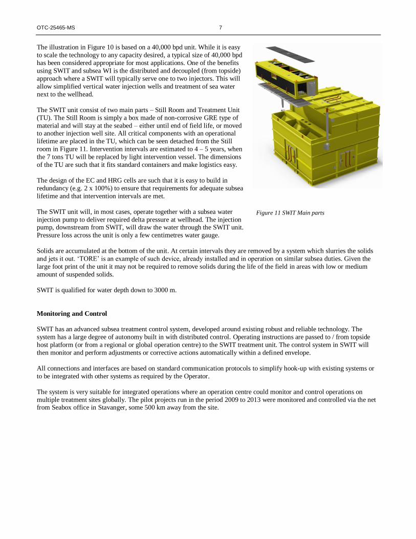
The SWIT unit consist of two main parts – Still Room and Treatment Unit
(TU). The Still Room is simply a box made of non-corrosive GRE type of
material and will stay at the seabed – either until end of field life, or moved to another injection well site. All critical components with an operational
lifetime are placed in the TU, which can be seen detached from the Still
room in Figure 11. Intervention intervals are estimated to 4 – 5 years, when
the 7 tons TU will be replaced by light intervention vessel. The dimensions
of the TU are such that it fits standard containers and make logistics easy.
The design of the EC and HRG cells are such that it is easy to build in
redundancy (e.g. 2 x 100%) to ensure that requirements for adequate subsea
lifetime and that intervention intervals are met.
The SWIT unit will, in most cases, operate together with a subsea water
injection pump to deliver required delta pressure at wellhead. The injection pump, downstream from SWIT, will draw the water through the SWIT unit.
Pressure loss across the unit is only a few centimetres water gauge.
Solids are accumulated at the bottom of the unit. At certain intervals they are removed by a system which slurries the solids
and jets it out. ‘TORE’ is an example of such device, already installed and in operation on similar subsea duties. Given the
large foot print of the unit it may not be required to remove solids during the life of the field in areas with low or medium
amount of suspended solids.
SWIT is qualified for water depth down to 3000 m.
Monitoring and Control
SWIT has an advanced subsea treatment control system, developed around existing robust and reliable technology. The
system has a large degree of autonomy built in with distributed control. Operating instructions are passed to / from topside
host platform (or from a regional or global operation centre) to the SWIT treatment unit. The control system in SWIT will
then monitor and perform adjustments or corrective actions automatically within a defined envelope.
All connections and interfaces are based on standard communication protocols to simplify hook-up with existing systems or
to be integrated with other systems as required by the Operator.
The system is very suitable for integrated operations where an operation centre could monitor and control operations on
multiple treatment sites globally. The pilot projects run in the period 2009 to 2013 were monitored and controlled via the net from Seabox office in Stavanger, some 500 km away from the site.
Figure 11 SWIT Main parts

8 OTC-25465-MS
Configurations
Figure 11 illustrates a standard typical 40,000 bpd SWIT unit. In most cases a pump is required to deliver the required
injection pressure at the wellhead for injecting the desired volume of water. In a relatively shallow area like the North Sea,
dropped object protection and over trawling protection are required. Standardized integrated solutions into 4-slot frames as
indicated in Figure 12 are often considered an effective solution (Pinchin, D. and Olsen, J.E. 2013). The 40,000 bpd unit is
designed such that it fits into one of the 4 slots. The water injection pump will be placed in the second slot and 2 slots are
available for injection wells. Studies have been conducted together with AkerSolutions to ensure all interfaces and integration
issues between treatment and pumping are addressed.
At other locations, modular approach is considered appropriate, as indicated in Figure 13. Different seabed soil conditions would also require different solutions, from suction pipes to simplified steel frame where seabed has good integrity.
The Subsea WI and SWIT are flexible and can be adjusted and configured to any application and site.
Business Case
In general, new discoveries are getting smaller and are found at deeper water locations, development costs are therefore
getting higher. Existing fields in production represent infrastructure with a limited design life. The time window for developing marginal near field opportunities is thefore limited (and running out in mature basins such as the UKCS).
Combined, the nature of the business is very dependent on new and more cost effective ‘tools in the toolbox’ to sustain
production.
SWIT, enabling Subsea WI, is such a ‘tool in the toolbox’. Subsea WI (using untreated / raw seawater) is already in operation
at few places in the world. Since subsea water treatment has not been feasible before the arrival of SWIT, the few places with
raw sea water injection have been a balance between pressure support requirements and risk of injectivity problems and
souring of the reservoir.
Two examples of ‘raw’ subsea WI are Tyrihans Field in Norway (Grynning, A. et al. 2009) and Albacora Field in Brazil
(Buk Jr, L. et al. 2013). Tyrihans is somewhat a special case where the water is injected into the water leg far from the
reservoir. At the time this was considered as the only way to get some pressure support.
Subsea water treatment is seen as a ‘missing link’ in the ‘subsea factory’, pursued by many Operators - Statoil in particular
(Økland, O. et al. 2013).
Moving water treatment from top side to subsea has a number of inherent benefits to all involved disciplines including
facilities engineers, well engineers and reservoir engineers. This is in contrast to the normal expectations of moving
equipment and processes subsea which results in compromises, increased costs, and risks of reduced regularity and
performance. This is not the case with SWIT.
Figure 13 Modular Approach Figure 12 SWIT and pump integrated in a standardized 4-slot frame

OTC-25465-MS 9
SWIT adds value to all major asset dimensions as illustrated in the conceptual spider diagram in Figure 14.
Figure 14 Large operational and economic benefits compared to topside WI solution
Subsea WI and SWIT has the potential to significantly reduce cost. The reduction in power required for WI also leads to
reduced emissions. Cost, HSE and regularity are all important factors for using Subsea WI and SWIT. However, the
flexibility to add water injection capacity when and where needed, particularly for sweep purposes, will lead to increased
production and recovery possibilities. This will in most cases be the biggest value driver.
Optimization of waterflood in mature fields are often constrained by topside water treatment and injection capacity, and
available well slots. Subsea WI and SWIT allows for phasing in further capacity when and where needed, independently from
topside. The only support required is electrical power from host or other nearby infrastructure.
A new development can take advantage of a number of knock-on effects by selecting Subsea WI and SWIT, as indicated in
Figure 15. Production and Water Injection will be ‘decoupled’. The topside will focus on production with simpler vertical
wells. Water treatment is moved to the seabed using SWIT. The structure (jacket or floater) will be reduced in size and
weight, and cost, due to no water treatment facility or long reach drilling (for water injection) capacity. The water injectors
are drilled as vertical wells where and when needed. This approach will reduce cost and provide flexibility to adapt and
optimize reservoir management as understanding of dynamic nature of the reservoir is gained with production history.
Figure 15 Subsea WI – ‘De-coupling’ production and injection
10 OTC-25465-MS
Using Subsea WI and SWIT allows for phased investments, avoiding upfront investments in water injection capacity
prematurely. Flexibility leads to a gentler investment profile with a total investment corresponding to actual capacity
required. The ‘decoupled’ approach also allows for parallel activities where production wells can be drilled by rig at topside
and water injectors by jack-up or floater in parallel, resulting in quicker build-up of production to plateau production.
As such, the approach with Subsea WI and SWIT reduces the total development Risk, and can increase the NPV.
Satellite Fields and Area Development
Most fields and developments have a number of discoveries and prospects nearby. Development of nearby satellites often
suffer lack of capacity at host facilities, including water treatment and injection capacity. Even if such capacity is available, the cost of providing water injection service to satellites increases dramatically with step-out distance. In particular the high
pressure water injection pipeline is expensive.
The SWIT technology requires only power and monitoring from a host facility. Both CAPEX and OPEX costs associated
with a subsea WI solution can be expected to be less than with topsides solution – principally due to the costs of installing a
high pressure WI pipeline. The cost differential will increase in favour of subsea WI the longer the step out distance from the
host platform becomes. This may enable satellites to be tied back at an earlier stage and at a significantly lower cost. In some
cases SWIT will therefore be ‘game changer’ to materialize discoveries within limited design lifetime windows of existing
infrastructure.
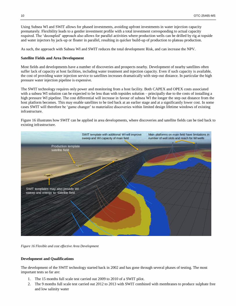
Figure 16 illustrates how SWIT can be applied in area developments, where discoveries and satellite fields can be tied back to
existing infrastructure.
Figure 16 Flexible and cost effective Area Development
Development and Qualifications
The development of the SWIT technology started back in 2002 and has gone through several phases of testing. The most
important tests so far are:
1. The 15 months full scale test carried out 2009 to 2010 of a SWIT pilot.
2. The 9 months full scale test carried out 2012 to 2013 with SWIT combined with membranes to produce sulphate free
and low salinity water
Main platforms on main field have limitations in
number of well slots and reach for WI wells
SWIT template with additional WI will improve
sweep and WI capacity of main field
Production template
satellite field
SWIT templates may also provide WI
sweep and energy to satellite field
OTC-25465-MS 11
Full scale SWIT pilot test, 2009 – 2010 (Pinchin, D. 2011)
Funding and technical guidance came from Joint Industry Project (JIP) members Shell, Total, ConocoPhillips, GDF SUEZ,
Seabox and Norwegian Research Council.
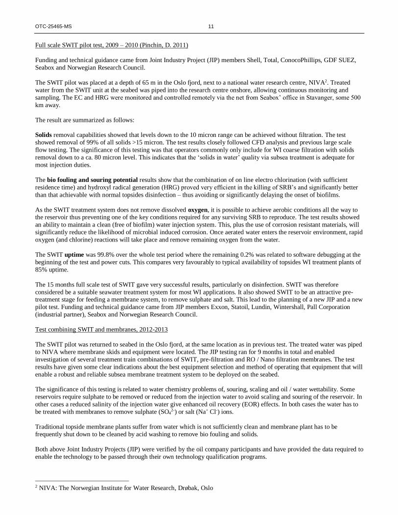
The SWIT pilot was placed at a depth of 65 m in the Oslo fjord, next to a national water research centre, NIVA2. Treated
water from the SWIT unit at the seabed was piped into the research centre onshore, allowing continuous monitoring and
sampling. The EC and HRG were monitored and controlled remotely via the net from Seabox’ office in Stavanger, some 500
km away.
The result are summarized as follows:
Solids removal capabilities showed that levels down to the 10 micron range can be achieved without filtration. The test
showed removal of 99% of all solids >15 micron. The test results closely followed CFD analysis and previous large scale
flow testing. The significance of this testing was that operators commonly only include for WI coarse filtration with solids
removal down to a ca. 80 micron level. This indicates that the ‘solids in water’ quality via subsea treatment is adequate for
most injection duties.
The bio fouling and souring potential results show that the combination of on line electro chlorination (with sufficient
residence time) and hydroxyl radical generation (HRG) proved very efficient in the killing of SRB’s and significantly better
than that achievable with normal topsides disinfection – thus avoiding or significantly delaying the onset of biofilms.
As the SWIT treatment system does not remove dissolved oxygen, it is possible to achieve aerobic conditions all the way to the reservoir thus preventing one of the key conditions required for any surviving SRB to reproduce. The test results showed
an ability to maintain a clean (free of biofilm) water injection system. This, plus the use of corrosion resistant materials, will
significantly reduce the likelihood of microbial induced corrosion. Once aerated water enters the reservoir environment, rapid
oxygen (and chlorine) reactions will take place and remove remaining oxygen from the water.
The SWIT uptime was 99.8% over the whole test period where the remaining 0.2% was related to software debugging at the
beginning of the test and power cuts. This compares very favourably to typical availability of topsides WI treatment plants of
85% uptime.
The 15 months full scale test of SWIT gave very successful results, particularly on disinfection. SWIT was therefore
considered be a suitable seawater treatment system for most WI applications. It also showed SWIT to be an attractive pre-treatment stage for feeding a membrane system, to remove sulphate and salt. This lead to the planning of a new JIP and a new
pilot test. Funding and technical guidance came from JIP members Exxon, Statoil, Lundin, Wintershall, Pall Corporation
(industrial partner), Seabox and Norwegian Research Council.
Test combining SWIT and membranes, 2012-2013
The SWIT pilot was returned to seabed in the Oslo fjord, at the same location as in previous test. The treated water was piped
to NIVA where membrane skids and equipment were located. The JIP testing ran for 9 months in total and enabled
investigation of several treatment train combinations of SWIT, pre-filtration and RO / Nano filtration membranes. The test
results have given some clear indications about the best equipment selection and method of operating that equipment that will
enable a robust and reliable subsea membrane treatment system to be deployed on the seabed.
The significance of this testing is related to water chemistry problems of, souring, scaling and oil / water wettability. Some
reservoirs require sulphate to be removed or reduced from the injection water to avoid scaling and souring of the reservoir. In
other cases a reduced salinity of the injection water give enhanced oil recovery (EOR) effects. In both cases the water has to
be treated with membranes to remove sulphate (SO42-) or salt (Na+ Cl-) ions.
Traditional topside membrane plants suffer from water which is not sufficiently clean and membrane plant has to be
frequently shut down to be cleaned by acid washing to remove bio fouling and solids.
Both above Joint Industry Projects (JIP) were verified by the oil company participants and have provided the data required to
enable the technology to be passed through their own technology qualification programs.
2 NIVA: The Norwegian Institute for Water Research, Drøbak, Oslo

12 OTC-25465-MS
Figure 17 gives and overview of the different components and the type of water produced at each stage – superior water for
normal water injection, water for matrix flooding, and low salinity (for EOR) and sulphate free water.
Figure 17 ’Tailor made’ water produced at seabed for water injection, for any type of reservoir and requirement
The findings of this JIP paves the way to advance existing subsea treatment techniques and provide ‘tailor made’ water quality for injection into reservoirs – thus enabling significant IOR / EOR improvements and economic development of
offshore oil fields.
Subsea WI / SWIT applications
SWIT is a new ‘tool in the toolbox’ which opens for new ways of developing new fields and optimizing existing fields.
SWIT can be used in many different ways, the list below illustrates a wide range of potential water treatment applications and
configurations (including some hybrid solutions):
1. New field developments – Significant benefits could include: Flexibility in reservoir drainage strategy (e.g. phased
introduction), reduced size and weight on structures, cost and utilities savings, and decoupled WI well drilling.
2. Optimising existing fields in production – Revitalising WI capacity and well locations could lead to pin pointing
infill locations for improved sweep. Acting on ‘real time’ information like production, pressure and new seismic
surveys tracking the water flood front and identifying unswept oil by new injection points. Subsea WI could
therefore be a ‘game changer’ in putting the reservoir engineer in ‘the driving seat’ and optimizing recovery based
on understanding of the reservoir, not limited by facility and infrastructure constraints.
3. Tie-back of satellites – SWIT allows in many cases a significant lower development cost making nearby potentials
profitable – with minimal implications to the host platform.
4. Unreliable / expired lifetime of existing WI facilities. E.g. #1: reinstatement of WI in satellite fields if water
injection pipeline has corroded. Easy installation with no pipeline crossing issues. At end of field life the unit can be
moved to new location. E.g. #2: Install SWIT unit next to existing platform feeding water to dry wells on topside,
saving weight and place.
5. Re-pressurize tail-end gas (and oil) fields where reservoir pressure is lower than hydrostatic head, allowing for
‘injection’ without pump (‘dump’ water into the reservoir)
Treatment
Additional removal of particles down to < 0,1 my
Superior water quality for matrix flooding
Any required quality water including Low Salinity or Sulphate free water
SWIT:
Disinfection
Mineralization
(HRG) of organics
Removal of 99% of
particles > 24 my
Superior water for
normal WI
Treatment
Treatment
Low Sal Low Sul Matrix Flooding SWIT water
OTC-25465-MS 13
6. Gas Fields – Enhanced Gas Recovery. Some fields experience limited aquifer support and long term planning
includes pressure support. With depleted reservoir pressure water can be ‘dumped’ into the reservoir.
7. Feed to topsides membrane plants. If sulphate removal or Low Salinity injection is required for EOR. A SWIT
unit placed next to the platform will provide superior quality water to feed topside membranes thus improving
membrane lifetime and treatment plant uptime.
8. Feed to subsea membrane plants. A complete integrated subsea facility including membrane systems is currently
being processed for final qualification and is expected to be available for operation in 2015.
9. Testing of formation injectivity for potential CO2 storage purposes
10. Cooling water: prevention of fouling in cooling water systems for both topsides and subsea equipment.
Produced Water
The treatment and disposal of produced water (PW) is a common problem for topsides production facilities. The three most
common ways of dealing with PW water are to:
1. Treat for overboard disposal (in accordance with strict environmental discharge regulations)
2. Treat for injection into loss / disposal zone well(s)
3. Treat for injection into WI well(s) for IOR purposes.
In order to improve environmental impacts whilst improving oil recovery levels, option 3) is seen by many operators as being the preferred option – if achievable. Problems associated with injection of PW for IOR are well documented (Khatib, Z. and
Verbeek, P. 2002, His, C.S. et al.1994, Flatval, K. B. et al 2004, Guan, L. et al. 2005) and are mainly associated with:
Water quality issues (very variable oil and solids content)
Availability of sufficient quantities of PW at stable flow rates
Souring and scaling potential when remixed with reservoir fluids
During recent years the cleaning capabilities of PW treatment plant has improved significantly. Mixing of PW with seawater
can overcome the problems of stable flow but significantly adds to the problem of souring and scaling potential – due to the
high sulphate content of seawater. It is therefore an intention that the SWIT + membrane technology may be used to provide
sulphate free injection water which in turn could enable mixing with PW for IOR purposes.
Discussion
At the onset of a field development, information regarding required injection flow rate, required water quality, flood patterns and number of injection points / wells, is limited to that obtained from an exploration / appraisal well. Reservoir cores, well
fluid sampling and other information gained from the appraisal well is then combined with other information to provide an
estimation of production rates for the field. This combined with fluid compositions, pressures, temperatures etc. are used for
production facilities design.
It is by no means uncommon for these estimations to be incorrect when it comes to the actual field conditions experienced
under operating conditions and subsequently grow in variation as the field operational life progresses.
Design of a WI plant will normally fall into these initial (pre-production) design considerations for the platform facility and
hence be ‘locked in’ for the duration of the field life – unless changes are economically justified. Traditional water injection
from offshore facilities is therefore unlikely to be designed for optimal field drainage.
Subsea water injection can provide a good deal of flexibility in being able to adjust field drainage strategies to meet actual
reservoir conditions and production trends. Being able to adjust WI to meet ongoing field situations can include:
Timing: WI can be implemented as / when required, into the areas of the reservoir most receptive to pressure
maintenance / water drive.
Flow rates: WI quantities can be adjusted to meet requirements.
Flood patterns: the ability to introduce flood patterns that most suit the reservoir can be implemented. More areas
of the reservoir (pockets of bypassed oil) can become recoverable.
Drilling: being able to decouple the drilling of water injection wells and production wells will mean that the

14 OTC-25465-MS
platform drilling facilities can be used solely for production optimisation. A remote drilling rig can be employed to
drill the (shorter, less deviated) WI wells on a timescale to suit production.
Water Quality: the existing technology qualified SWIT system can provide seawater at as good / better quality than
is required by the majority of reservoirs. SWIT + membranes enables the possibility to inject ‘tailor made’ water
thus improving oil production potential (EOR) and also overcoming problems with souring and scaling.
This paper has described the technology of subsea water treatment available via the SWIT system and has explained the
testing conducted and readiness for field deployment as seen by major operators. It can also be seen that the SWIT
technology can be used in different ways for a variety of applications.
Conclusion
The SWIT technology offers new ways of managing reservoirs and assets, to reduce cost and emissions and for IOR and
EOR. It allows to put the reservoir engineer into the ‘driving seat’, optimizing oil production and recovery based on reservoir
insight and opportunities, and not limited by pre-set topside and slot constraints. SWIT is an enabler for marginal satellite
developments, and for optimizing area developments. The capability to produce any quality water at seabed will enable cost
efficient low salinity projects for EOR.
SWIT enables a step change in reservoir and asset management that can accelerate production and increase recovery.

OTC-25465-MS 15
Nomenclature
bpd Barrels per day
CBR Crude oil Brine Rock (system)
CFD Computational Fluid Dynamics
EC Electrochlorinator
GAB General Aerobic Bacteria
HF Hollow Fibre
HRG Hydroxyl Radical Generator
ITF Industry Technology Facilitator
JIP Joint Industry Project MF Microfiltration
MIC Microbial Induced Corrosion
NF Nanofiltration
NIVA Norwegian Institute for Water Research
OOIP Original Oil In Place
ORP Oxidation Reduction Potential
ppm parts per million
PW Produced Water
RO Reverse Osmosis
SDI Silt Density Index
SRB Sulphate Reducing Bacteria
SWIT Subsea Water Intake & Treatment TRL Technology Readiness Level
TU Treatment Unit
References
1. Pinchin, D. 2011. Subsea Water Treatment Comes of Age. Paper OTC 21578-PP presented at OTC, Houston, 2-5
May 2011.
2. Olsen, J.E. and Pinchin, D. 2013. Subsea Water Treatment and Injection Station. Paper SPE 166576 presented at
Offshore Europe Conference, Aberdeen, UK, 3-6 September 2013.
3. Buk Jr, L. et al. 2013. Albacora Subsea Raw Water Injection Systems. Paper OTC 24167 presented at OTC,
Houston, 6-9 May 2013.
4. Grynning, A. et al. 2009. Tyrihans Raw Seawater Injection. Paper OTC 20078 presented at OTC, Houston, 4-7 May
2009.
5. Austad, T. 2012. Water Based EOR in Carbonates and Sandstones: New Chemical Understanding of the EOR-
Potential Using “Smart Water”. Course, Muscat 15 April 2012 (also available on the net).
6. Guan, L. et al. 2005. Water Injectivity – What We Have Learned in the Past 30 Years. Paper 2005-178 presented in
Calgary 7-9 June 2005
7. Gao, C. 2007. Factors Affecting Particle Retention in Porous Media. Emirates Journal for Engineering Research, 12
(3), 1-7 (2007)
8. Khatib, Z. and Verbeek, P. 2002. Water to Value – Produced Water Management for Sustainable Development of
Mature and Green Fields. Paper SPE 73853 presented in Kuala Lumpur 20-22 March 2002.
9. His, C.S. et al. 1994. Formation Injectivity Damage Due to Produced Water Reinejction. Paper SPE 27395 presented
in Lafayette, Louisiana, 7-10 February 1994
10. Flatval, K. B. et al. 2004. Building the Case for Raw Seawater Injection Scheme in Barton. Paper SPE 88568
presented in Perth, 18-20 October 2004
11. Kraft, A. 2007. Doped Diamond: A Compact Review on a New, Versatile Electrode Material, Int. J. Electrochem.
Sci., 2 (2007) 355 – 385 (367)
12. Økland, O. et al. 2013. Steps to the Subsea Factory. Paper OTC 24307 presented at OTC, Rio de Janeiro, 29-31
October 2013.
13. Dake, L.P. 1978. Fundamentals of Reservoir Engineering. Elsevier Scientific Publishing Company. Ninth
impression 1986.


