Optimized Stereo Recontrucion Using Hardware 3d Graphic Card
9
Optimized Stereo Reconstruction Using 3D Graphics Hardware Christopher Zach, Andreas Klaus, Bernhard Reitinger ∗ and Konrad Karner August 28, 2003 Abstract In this paper we describe significant enhancements of our recently developed stereo reconstruction software exploiting features of commodity 3D graphics hard- ware . The aim of our resea rch is the acceleration of dense reco nstru ction s from stereo images. The im- plementation of our hardware based matching proce- dure avoids loss of accuracy due to the limited preci- sion of calculations performed in 3D graphics proces- sors. In this work we tar get on impro ving the time to obtain reconstructions for images with small res- olutio n, and we cov ered other enhancement s to in- crease the speed for highly detailed reconstructions. Our optimized implementation is able to gene rate up to 130000 depth v alues per sec ond on sta nda rd PC hardware. Additionally we ext end the origin al epipolar reconstruction approach to estimate dispar- ities between two images without known orientation. Therefore we can calculate e.g. the optical flow be- tween successive images using 3D hardware. 1 In tr oduct ion The automatic creation of digital 3D models from im- ages of real objects comprise a main step in the gen- eration of virtual environments and is still a challeng- ing resea rch topic. Man y stereo reconstruction algo- rithms to obtain models from images were proposed, and almost all approaches are based on traditional computations performed in the main CPU. Very re- cently few methods were proposed, that exploit the parallelism and special-purpose circuits found in cur- rent 3D graphics hardware to accelerate the recon- struction process. In our earlier work [20] we proposed a hierarchi- cal, area- based stereo match ing procedure on pro- grammable 3D graphics hardwa re. Alt hou gh the method is sti ll sig nificantly slo we r tha n the plane sweeping approach proposed by Yang et al. [19] (us- ing a five camera setup), our approach provides good result s with a calibrated stereo setup. Addit ionally the domain of achieved depth values is larger due to the local mesh refinements emplo yed in our method. In this work we present substantial performance enhancement s of our matching procedure without los- ing accurac y . The key idea is the amortization of compu tatio ns acro ss sev eral iteration s of the algo- rithm. F urthe r, we implement a dispar ity match ing method to calculate the optical flow between two im- ages. Aft er a sec tion on relate d wo rk we briefl y out - line our original hardw are-b ased stereo reconstruc- tion method in Section 3. Our recent impro vement s are presented in Sec tio ns 4–7. Sec tion 8 presents benchmark compar isons between the ori ginal and new method to illustrate the achieved performance gain, and finally we outline future work. 2 Re la te d W or k 2.1 Reconstructi on from Stereo Im- ages Stereo matching is the process of finding correspond- ing or homologous points in two or more images and is an essential task in computer vision. We distinguish bet we en fea tur e and area based method s. F eatur e based methods incline to spars e but accurate results, whereas area based methods de- 1
Transcript of Optimized Stereo Recontrucion Using Hardware 3d Graphic Card

8/3/2019 Optimized Stereo Recontrucion Using Hardware 3d Graphic Card
http://slidepdf.com/reader/full/optimized-stereo-recontrucion-using-hardware-3d-graphic-card 1/9
Optimized Stereo Reconstruction Using 3D Graphics Hardware
Christopher Zach, Andreas Klaus, Bernhard Reitinger∗ and Konrad Karner
August 28, 2003
Abstract
In this paper we describe significant enhancements of our recently developed stereo reconstruction softwareexploiting features of commodity 3D graphics hard-ware. The aim of our research is the acceleration of dense reconstructions from stereo images. The im-plementation of our hardware based matching proce-dure avoids loss of accuracy due to the limited preci-sion of calculations performed in 3D graphics proces-sors. In this work we target on improving the timeto obtain reconstructions for images with small res-olution, and we covered other enhancements to in-crease the speed for highly detailed reconstructions.Our optimized implementation is able to generateup to 130000 depth values per second on standardPC hardware. Additionally we extend the original
epipolar reconstruction approach to estimate dispar-ities between two images without known orientation.Therefore we can calculate e.g. the optical flow be-tween successive images using 3D hardware.
1 Introduction
The automatic creation of digital 3D models from im-ages of real objects comprise a main step in the gen-eration of virtual environments and is still a challeng-ing research topic. Many stereo reconstruction algo-rithms to obtain models from images were proposed,
and almost all approaches are based on traditionalcomputations performed in the main CPU. Very re-cently few methods were proposed, that exploit theparallelism and special-purpose circuits found in cur-rent 3D graphics hardware to accelerate the recon-struction process.
In our earlier work [20] we proposed a hierarchi-cal, area-based stereo matching procedure on pro-grammable 3D graphics hardware. Although themethod is still significantly slower than the plane
sweeping approach proposed by Yang et al. [19] (us-ing a five camera setup), our approach provides goodresults with a calibrated stereo setup. Additionallythe domain of achieved depth values is larger due tothe local mesh refinements employed in our method.
In this work we present substantial performanceenhancements of our matching procedure without los-ing accuracy. The key idea is the amortization of computations across several iterations of the algo-rithm. Further, we implement a disparity matchingmethod to calculate the optical flow between two im-ages.
After a section on related work we briefly out-
line our original hardware-based stereo reconstruc-tion method in Section 3. Our recent improvementsare presented in Sections 4–7. Section 8 presentsbenchmark comparisons between the original andnew method to illustrate the achieved performancegain, and finally we outline future work.
2 Related Work
2.1 Reconstruction from Stereo Im-
ages
Stereo matching is the process of finding correspond-ing or homologous points in two or more images andis an essential task in computer vision.
We distinguish between feature and area basedmethods. Feature based methods incline to sparsebut accurate results, whereas area based methods de-
1
8/3/2019 Optimized Stereo Recontrucion Using Hardware 3d Graphic Card
http://slidepdf.com/reader/full/optimized-stereo-recontrucion-using-hardware-3d-graphic-card 2/9
liver dense point clouds. The former methods use lo-cal features that are extracted from intensity or color
distribution. These extracted feature vectors are uti-lized to solve the correspondence problem. Areabased methods employ a similarity constraint, wherecorresponding points are assumed to have similar in-tensity or color within a local window. Frequently itis necessary to incorporate a continuity constraint toobtain better reconstructions in homogeneously tex-tured regions. If the relative orientations of the im-ages are known, the search for corresponding pointscan be restricted to epipolar lines and the searchproblem is only one-dimensional. This leads to sig-nificant improvements in accuracy as well in perfor-mance. A good collection and comparison of differ-ent matching methods can be found in [3]. Brownet al. [1] give an overview of recent developments of stereo vision methods. In order to obtain faster con-vergence and to avoid local minima we employ a hi-erarchical approach for matching [8, 10], which is inparticular inspired by the work of Redert et al. [15]
Some applications for stereo matching require fastor even real-time reconstructions, e.g. robot naviga-tion or real-time view synthesis. The Triclops visionsystem [7] consists of a hardware setup with threecameras and appropriate software for realtime stereomatching. The system is able to generate depth im-
ages at a rate of about 20Hz for images up to 320x240pixels on current PC hardware. The software ex-ploits the particular orientation of the cameras andMMX/SSE instructions available on current CPUs.In contrast to the Triclops system our approach canhandle images from cameras with arbitrary relativeorientation.
Yang et al. [19] developed a fast stereo reconstruc-tion method performed in 3D hardware by utilizinga plane sweep approach to find correct depth values.The number of iterations is linear in the requestedresolution of depth values, therefore this method is
limited to rather coarse depth estimation. Further,their approach requires a true multi-camera setup tobe robust, since the error function is only evaluatedfor single pixels. In later work the method was mademore robust using trilinear texture access to accumu-late error differences within a window [18].
2.2 Accelerated Computations in
Graphics Hardware
Even before programmable graphics hardware wasavailable, the fixed function pipeline of 3D graphicsprocessors was utilized to accelerate numerical cal-culations [5, 6] and even to emulate programmableshading [13]. The introduction of a quite generalprogramming model for vertex and pixel process-ing [9, 14] opened a very active research area. Theprimary application for programmable vertex andfragment processing is the enhancement of photore-alism in interactive visualization systems (e.g. [2, 4])and entertainment applications ([11, 12]).
Recently several authors identified current graph-
ics hardware as a kind of auxiliary processing unitto perform SIMD (single instruction, multiple data)operations efficiently. Thompson et al. [17] im-plemented several non-graphical algorithms to runon programmable graphics hardware and profiledthe execution times against CPU based implementa-tions. They concluded that an efficient memory inter-face (especially when transferring data from graphicsmemory into main memory) is still an unsolved issue.For the same reason our implementation is designedto minimize memory traffic between graphics hard-ware and main memory. Strzodka [16] discusses theemulation of higher precision numbers with several8 bit color channels. We faced a similar problem of manipulating large integer values and storing themin the frame buffer and texture maps for later use.
3 Overview of Our Matching
Procedure
The original implementation of our 3D graphics hard-ware based matching procedure is described in [20].The matching algorithm essentially warps the left andthe right image onto the current triangular 3D mesh
hypothesis according to the relative orientation be-tween the images. The projection of the mesh into theleft image constitutes always a regular grid (i.e. theleft image is never distorted). The warped images aresubtracted and the sum of absolute diffenences is cal-culated in a window around the mesh vertices. New
2essentially:ba?n cha'twarp imagine: a?nh bi. bie^n' da.ngTriangular: co' hi`nh tam giachypothesis:gia thuye'tconstitute: ca^u' tao.
grid:luoi' toa. do.
8/3/2019 Optimized Stereo Recontrucion Using Hardware 3d Graphic Card
http://slidepdf.com/reader/full/optimized-stereo-recontrucion-using-hardware-3d-graphic-card 3/9
mesh hypotheses are generated by moving mesh ver-tices along the camera rays for the left image (epipo-
lar constraint). Different mesh hypotheses generatedifferent local errors and the matching procedure de-termines the point-wise optimal depth component of vertices.
The main steps of the algorithm, namely imagewarping and differencing, sum of absolute differencescalculation, and finding the optimal depth value areperformed on the graphics processing unit. The mainCPU executes the control flow and updates the cur-rent mesh hypothesis. In order to minimize transferbetween host and graphics memory most changes ap-plied to the current mesh geometry are only appliedvirtually without requiring real update of 3D vertices.For details we refer to our earlier work.
The control flow of the matching algorithm consistsof 3 nested loops:
1. The outermost loop adds the hierarchical ap-proach to our method and reduces the proba-bility of local minima e.g. imposed by repetitivestructures. In every iteration the mesh and im-age resolutions are doubled. The refined mesh isobtained by linear (and optionally median) fil-tering of the coarser one.
2. The inner loop chooses a set of independent ver-
tices to be modified and updates the depth val-ues of these vertices after performing the inner-most loop. In order to avoid influence of depthchanges of neighboring vertices, only one quarterof the vertices can be modified simultaneously.
3. The innermost loop evaluates depth variationsfor candidate vertices selected in the enclosingloop. The best depth value is determined by re-peated image warping and error calculation wrt.the tested depth hypothesis. The body of thisloop runs entirely on the 3D graphics processingunit (GPU).
Figure 1 illustrates the key steps of the algorithm.The result of the procedure is a 3D mesh or pointcloud consisting of the sampling points. In the cur-rent framework we use one sampling vertex every fourpixels, hence images with one megapixel resolutionyield to a mesh with 256× 256 vertices.
4 Amortized Difference Image
GenerationFor larger image resolutions (e.g. 1024× 1024) ren-dering of the corresponding mesh generated by thesampling points takes a considerable amount of time.In the 1-megapixel case the mesh consists of approxi-mately 131 000 triangles, which must be rendered forevery depth value (several hundred times in total).Especially on mobile graphic boards mesh processingimplies a severe performance penalty: stereo match-ing of two 256×256 images has comparable speed ona desktop GPU and on a usually slower mobile GPUintended for laptop PCs, but matching 1-megapixel
images requires two times longer on the mobile GPU.In order to reduce the number of mesh drawings
up to four depth values are evaluated in one pass.We use multitexturing facilities to generate four tex-ture coordinates for different depth values within thevertex program. The fragment shader calculates theabsolute differences for these deformations simultane-ously and stores the results in the four color channels(red, green, blue and alpha). Note that the meshhypothesis is updated infrequently and the actuallyevaluated mesh is generated within the vertex shaderby deforming the incoming vertices according to thecurrent displacement.
The vertex program has now more work to per-form, since four transformations (matrix-vector mul-tiplications) are executed to generate texture coordi-nates for the right image for each vertex. Neverthe-less, the obtained timing results (see Section 8) in-dicate a significant performance improvement by uti-lizing this approach. Several operations are executedonly once for up to 4 mesh hypotheses: transferringvertices and transforming them into window coordi-nates, triangle rasterization setup and texture accessto the left image.
5 Chunked Image TransformsIn contrast to Yang and Pollefeys [18] we calculatethe error within a window explicitly using multiplepasses. In every pass four adjacent pixels are ac-cumulated and the result is written to a temporary
3
absolute: tuyet doi'optimal: to^i uuminima=minimum
ose:chiu.
amortized: tat' dan` , giam dan`
facilitiephuon
explicitly: ro~ rang`
8/3/2019 Optimized Stereo Recontrucion Using Hardware 3d Graphic Card
http://slidepdf.com/reader/full/optimized-stereo-recontrucion-using-hardware-3d-graphic-card 4/9
Minimum calculation
and optimal depth
New minimal error
Update mesh hypothesis
Old minimal error
Absolute difference
differences
Sum of abs.
Left image
Range image
Right image
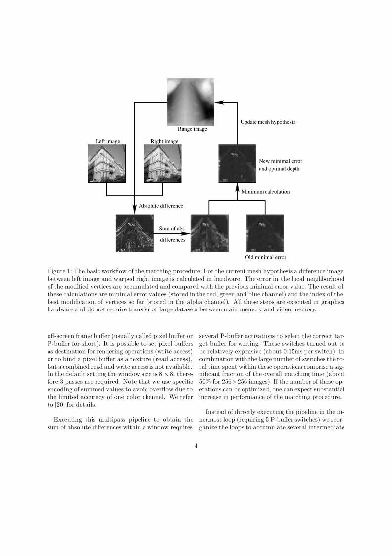
Figure 1: The basic workflow of the matching procedure. For the current mesh hypothesis a difference imagebetween left image and warped right image is calculated in hardware. The error in the local neighborhoodof the modified vertices are accumulated and compared with the previous minimal error value. The result of
these calculations are minimal error values (stored in the red, green and blue channel) and the index of thebest modification of vertices so far (stored in the alpha channel). All these steps are executed in graphicshardware and do not require transfer of large datasets between main memory and video memory.
off-screen frame buffer (usually called pixel buffer orP-buffer for short). It is possible to set pixel buffersas destination for rendering operations (write access)or to bind a pixel buffer as a texture (read access),but a combined read and write access is not available.In the default setting the window size is 8× 8, there-fore 3 passes are required. Note that we use specific
encoding of summed values to avoid overflow due tothe limited accuracy of one color channel. We referto [20] for details.
Executing this multipass pipeline to obtain thesum of absolute differences within a window requires
several P-buffer activations to select the correct tar-get buffer for writing. These switches turned out tobe relatively expensive (about 0.15ms per switch). Incombination with the large number of switches the to-tal time spent within these operations comprise a sig-nificant fraction of the overall matching time (about50% for 256×256 images). If the number of these op-
erations can be optimized, one can expect substantialincrease in performance of the matching procedure.
Instead of directly executing the pipeline in the in-nermost loop (requiring 5 P-buffer switches) we reor-ganize the loops to accumulate several intermediate
4
8/3/2019 Optimized Stereo Recontrucion Using Hardware 3d Graphic Card
http://slidepdf.com/reader/full/optimized-stereo-recontrucion-using-hardware-3d-graphic-card 5/9
Difference
image 1
Difference
image 2
Difference
image 4
Difference
image 3
n x n
n/2 x n/2
pixel summation
for every iteration
pixel summation
every four iterations
pixel summation
once per block
n x n
n x n
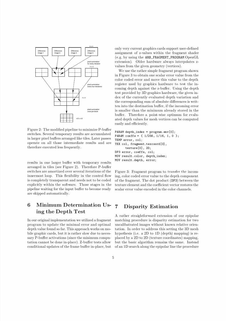
Figure 2: The modified pipeline to minimize P-bufferswitches. Several temporary results are accumulatedin larger pixel buffers arranged like tiles. Later passesoperate on all those intermediate results and aretherefore executed less frequently.
results in one larger buffer with temporary results
arranged in tiles (see Figure 2). Therefore P-bufferswitches are amortized over several iterations of theinnermost loop. This flexibility in the control flowis completely transparent and needs not to be codedexplicitly within the software. Those stages in thepipeline waiting for the input buffer to become readyare skipped automatically.
6 Minimum Determination Us-
ing the Depth Test
In our original implementation we utilized a fragment
program to update the minimal error and optimaldepth value found so far. This approach works on mo-bile graphic cards, but it is rather slow due to neces-sary P-buffer activations (since the minimum compu-tation cannot be done in-place). Z-buffer tests allowconditional updates of the frame buffer in-place, but
only very current graphics cards support user-definedassignment of z-values within the fragment shader
(e.g. by using the ARB_FRAGMENT_PROGRAM OpenGLextension). Older hardware always interpolates z-values from the given geometry (vertices).
We use the rather simple fragment program shownin Figure 3 to obtain one scalar error value from thecolor coded error and move this value to the depthregister used by graphics hardware to test the in-coming depth against the z-buffer. Using the depthtest provided by 3D graphics hardware, the given in-dex of the currently evaluated depth variation andthe corresponding sum of absolute differences is writ-ten into the destination buffer, if the incoming erroris smaller than the minimum already stored in thebuffer. Therefore a point-wise optimum for evalu-ated depth values for mesh vertices can be computedeasily and efficiently.
PARAM depth_index = program.env[0];
PARAM coeffs = { 1/256, 1/16, 1, 0 };
TEMP error, col;
TEX col, fragment.texcoord[0],
texture[0], 2D;
DP3 error, coeffs, col;
MOV result.color, depth_index;
MOV result.depth, error;
Figure 3: Fragment program to transfer the incom-ing, color coded error value to the depth componentof the fragment. The dot product (DP3) between thetexture element and the coefficient vector restores thescalar error value encoded in the color channels.
7 Disparity Estimation
A rather straightforward extension of our epipolarmatching procedure is disparity estimation for two
uncalibatrated images without known relative orien-tation. In order to address this setting the 3D meshhypothesis (i.e. a 2D to 1D (depth) mapping) is re-placed by a 2D to 2D (texture coordinates) mapping,but the basic algorithm remains the same. Insteadof an 1D search along the epipolar line the procedure
5

8/3/2019 Optimized Stereo Recontrucion Using Hardware 3d Graphic Card
http://slidepdf.com/reader/full/optimized-stereo-recontrucion-using-hardware-3d-graphic-card 6/9
Disparity map
Figure 4: 2D search for the appropriate disparityvalue to warp the right image. The arrows indicatesearch directions at the sampling point.
performs a 2D search for appropriate disparity val-ues. In this setting the rather complex vertex shaderto generate texture coordinates for the right imageused for epipolar matching can be omitted. In everyiteration the current 2D disparity map hypothesis ismodified in vertical and horizontal direction and eval-uated (Figure 4). With this approach it is possibleto find corresponding regions in typical small base-line settings (i.e. only small change in position androtation between the two images).
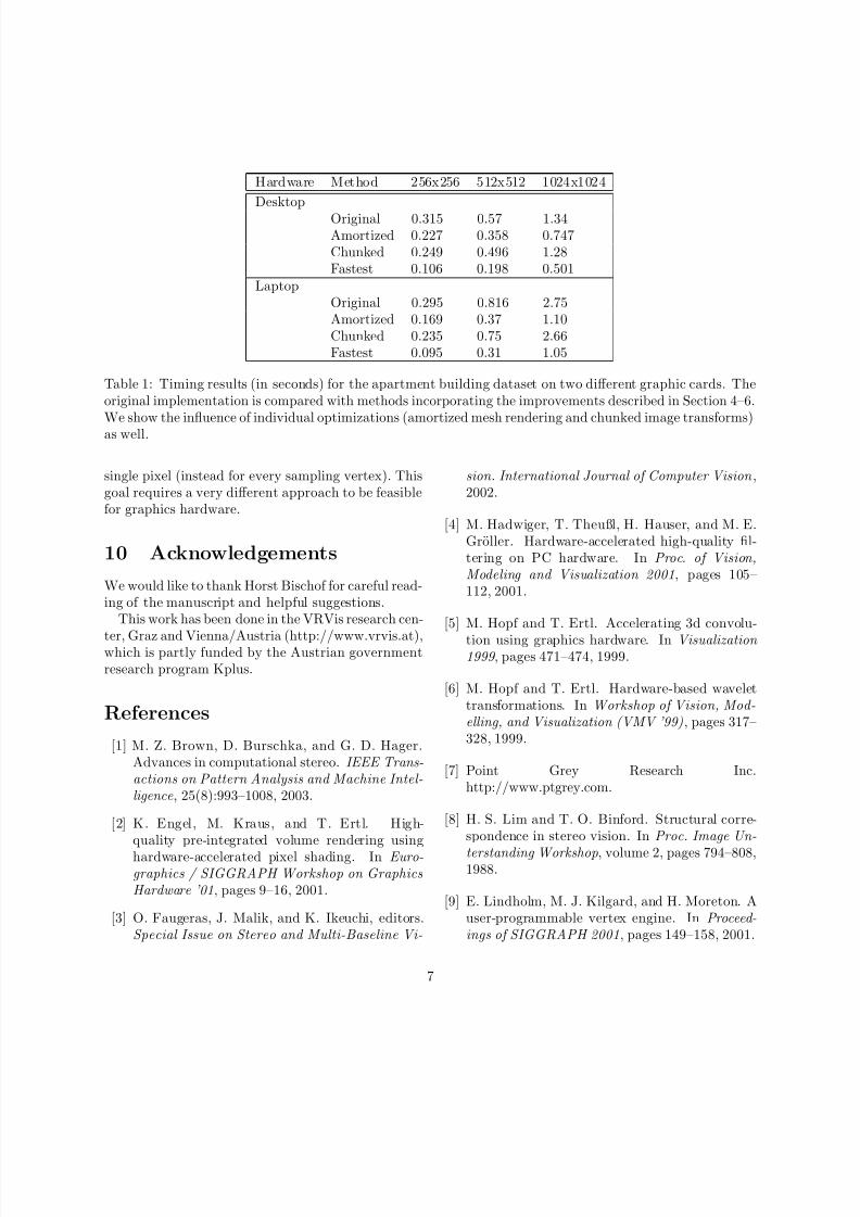
8 ResultsWe run timing experiments on a desktop PC with anAthlon XP 2700 and an ATI Radeon 9700 and ona laptop PC with a mobile Athlon XP 2200 and anATI Radeon 9000 Mobility. Table 1 depicts timingresults for those two hardware setups and illustratesthe effect of the various optimizations mentioned inthe previous sections. The timings were obtainedfor epipolar stereo matching of the dataset shownin Figure 5. The total number of evaluated meshhypothesis is 224 (256x256), 280 (512x512) and 336(1024x1024). In the highest resolution (1024x1024)
each vertex is actually tested with 84 depth valuesout of a range of approximately 600 possible values.Because of limitations in graphics hardware we arecurrently restricted to images with power of two di-mensions.
We compared the original unoptimized implemen-
tation with the methods incorporating only one of theenhancements described in Section 4 and Section 5
and with the fasted method using all enhancements(including the technique described in Section 6 on thedesktop PC). The desktop PC is surprisingly slowfor lower resolutions, but the faster vertex process-ing and increased fill rate is obvious for the highesttested resolution. Although the benchmark resultsare given only for the particular dataset, timings forother datasets are similar (but not always completelyidentical).
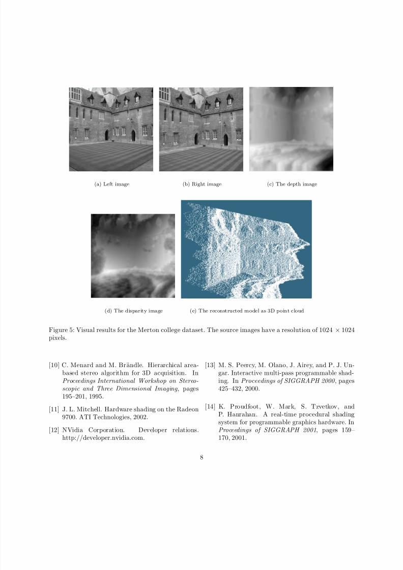
Figure 5 gives visual results for stereo images show-ing the Merton college. Figure 5(a) and (b) comprisethe source images, and Figure 5(c) shows the depth
image generated by the epipolar matching procedure,whereas Figure 5(d) displays the magnitude of dis-parity between the source images. Brighter regionsindicate larger disparities. Finally, Figure 5(e) showsa screenshot of the 3D point cloud obtained by thematching procedure.
9 Conclusions and Future
Work
We presented several significant performance en-
hancements of our 3D hardware based stereo match-ing procedure to obtain faster reconstructions with-out loss in accuracy compared to the original ap-proach. Further, we illustrated graphics hard-ware based disparity estimation descending from theepipolar stereo matcher.
With the emergence of consumer level DirectX 9graphic boards supporting floating point precision forcolor channels and rather orthogonal and powerfulinstruction sets, more advanced hardware based al-gorithms to obtain 3D models from multiple imagescan be implemented. We intend to utilize an adaptivemesh refinement approach instead of the pure regular
grid to generate suitable 3D models in regions withlittle texture information. Alternatively we have ini-tial support for a smoothing term incorporated intothe error value to favor planar reconstructions in ho-mogeneous regions. Especially for disparity matchingit is an objective to obtain disparity vectors for every
6
8/3/2019 Optimized Stereo Recontrucion Using Hardware 3d Graphic Card
http://slidepdf.com/reader/full/optimized-stereo-recontrucion-using-hardware-3d-graphic-card 7/9
Hardware Method 256x256 512x512 1024x1024
DesktopOriginal 0.315 0.57 1.34Amortized 0.227 0.358 0.747Chunked 0.249 0.496 1.28Fastest 0.106 0.198 0.501
LaptopOriginal 0.295 0.816 2.75Amortized 0.169 0.37 1.10Chunked 0.235 0.75 2.66Fastest 0.095 0.31 1.05
Table 1: Timing results (in seconds) for the apartment building dataset on two different graphic cards. Theoriginal implementation is compared with methods incorporating the improvements described in Section 4–6.We show the influence of individual optimizations (amortized mesh rendering and chunked image transforms)as well.
single pixel (instead for every sampling vertex). Thisgoal requires a very different approach to be feasiblefor graphics hardware.
10 Acknowledgements
We would like to thank Horst Bischof for careful read-ing of the manuscript and helpful suggestions.
This work has been done in the VRVis research cen-
ter, Graz and Vienna/Austria (http://www.vrvis.at),which is partly funded by the Austrian governmentresearch program Kplus.
References
[1] M. Z. Brown, D. Burschka, and G. D. Hager.Advances in computational stereo. IEEE Trans-actions on Pattern Analysis and Machine Intel-ligence, 25(8):993–1008, 2003.
[2] K. Engel, M. Kraus, and T. Ertl. High-quality pre-integrated volume rendering using
hardware-accelerated pixel shading. In Euro-graphics / SIGGRAPH Workshop on GraphicsHardware ’01, pages 9–16, 2001.
[3] O. Faugeras, J. Malik, and K. Ikeuchi, editors.Special Issue on Stereo and Multi-Baseline Vi-
sion. International Journal of Computer Vision ,2002.
[4] M. Hadwiger, T. Theußl, H. Hauser, and M. E.Groller. Hardware-accelerated high-quality fil-tering on PC hardware. In Proc. of Vision,Modeling and Visualization 2001, pages 105–112, 2001.
[5] M. Hopf and T. Ertl. Accelerating 3d convolu-
tion using graphics hardware. In Visualization 1999 , pages 471–474, 1999.
[6] M. Hopf and T. Ertl. Hardware-based wavelettransformations. In Workshop of Vision, Mod-elling, and Visualization (VMV ’99), pages 317–328, 1999.
[7] Point Grey Research Inc.http://www.ptgrey.com.
[8] H. S. Lim and T. O. Binford. Structural corre-spondence in stereo vision. In Proc. Image Un-
terstanding Workshop, volume 2, pages 794–808,1988.
[9] E. Lindholm, M. J. Kilgard, and H. Moreton. Auser-programmable vertex engine. In Proceed-ings of SIGGRAPH 2001, pages 149–158, 2001.
7
8/3/2019 Optimized Stereo Recontrucion Using Hardware 3d Graphic Card
http://slidepdf.com/reader/full/optimized-stereo-recontrucion-using-hardware-3d-graphic-card 8/9
(a) Left image (b) Right image (c) The depth image
(d) The disparity image (e) The reconstructed model as 3D point cloud
Figure 5: Visual results for the Merton college dataset. The source images have a resolution of 1024 × 1024pixels.
[10] C. Menard and M. Brandle. Hierarchical area-based stereo algorithm for 3D acquisition. InProceedings International Workshop on Stereo-scopic and Three Dimensional Imaging , pages
195–201, 1995.[11] J. L. Mitchell. Hardware shading on the Radeon
9700. ATI Technologies, 2002.
[12] NVidia Corporation. Developer relations.http://developer.nvidia.com.
[13] M. S. Peercy, M. Olano, J. Airey, and P. J. Un-gar. Interactive multi-pass programmable shad-ing. In Proceedings of SIGGRAPH 2000 , pages425–432, 2000.
[14] K. Proudfoot, W. Mark, S. Tzvetkov, andP. Hanrahan. A real-time procedural shadingsystem for programmable graphics hardware. InProceedings of SIGGRAPH 2001, pages 159–170, 2001.
8
8/3/2019 Optimized Stereo Recontrucion Using Hardware 3d Graphic Card
http://slidepdf.com/reader/full/optimized-stereo-recontrucion-using-hardware-3d-graphic-card 9/9
[15] A. Redert, E. Hendriks, and J. Biemond. Cor-respondence estimation in image pairs. IEEE
Signal Processing Magazine, pages 29–46, 1999.
[16] R. Strzodka. Virtual 16 bit precise operations onRGBA8 textures. In Proc. of Vision, Modeling and Visualization 2002 , pages 171–178, 2002.
[17] C. J. Thompson, S. Hahn, and M. Oskin. Us-ing modern graphics architectures for general-purpose computing: A framework and analy-sis. In 35th Annual IEEE/ACM International Symposium on Microarchitecture (MICRO-35),2002.
[18] R. Yang and M. Pollefeys. Multi-resolution real-time stereo on commodity graphics hardware.In Conference on Computer Vision and Pattern Recognition , 2003.
[19] R. Yang, G. Welch, and G. Bishop. Real-timeconsensus based scene reconstruction using com-modity graphics hardware. In Proceedings of Pa-cific Graphics, 2002.
[20] C. Zach, A. Klaus, M. Hadwiger, and K. Karner.Accurate dense stereo reconstruction usinggraphics hardware. In EUROGRAPHICS 2003,Short Presentations, 2003. available as report
from www.vrvis.at.
9