OPTIMAL RELIABILITY OF LifELINE LEVEE SYSTEMS UNDER ... · 1-14 Yucemen, M.S. and E.H. Vanmarcke,...
136
JBA-109-030-H-01 OPTIMAL RELIABILITY OF LifELINE LEVEE SYSTEMS UNDER MULTIPLE NATURAL HAZARDS by Jack R. Benjamin Frederick A. Webster This material Is based upon work supported by the National Science Foundation under Grant No. CEE 80-13038. Any opinions, findings, and conclusions or recommendations expressed In this publication are those of the authors anhd do not necessarily reflect the views of the National Science Foundation. August 1, 1984 Jack R. Benjamin & Associates. Inc. _ •• Consulting Engineers Mountain Bay Plaza, Suite 501 444 Castro Street, Mountain View, California 94041 II
Transcript of OPTIMAL RELIABILITY OF LifELINE LEVEE SYSTEMS UNDER ... · 1-14 Yucemen, M.S. and E.H. Vanmarcke,...
JBA-109-030-H-01
OPTIMAL RELIABILITY OF LifELINE LEVEE SYSTEMS
UNDER MULTIPLE NATURAL HAZARDS
by
Jack R. BenjaminFrederick A. Webster
This material Is based upon work supported bythe National Science Foundation under Grant No.CEE 80-13038.
Any opinions, findings, and conclusions orrecommendations expressed In this publicationare those of the authors anhd do not necessarilyreflect the views of the National ScienceFoundation.
August 1, 1984
Jack R. Benjamin & Associates. Inc. _ ••-~Consulting EngineersMountain Bay Plaza, Suite 501444 Castro Street, Mountain View, California 94041
II

109-030-H-0 1
Table of Contents
1• INTRODUCTION . • · · • · · · · · · · • • · • · • • · • · · .1-1
1• 1 Problem Statement and Summary · · • · · • • · • · · · · .1- 1
1.2 Levee Types • · · · · · • · • · · · • • • · • • .1-2
1.3 Report Organization · · · · · · • · · · · • · · · · · .1-2
1.4 References. • · · · · • · • · • · · · · · • · · .1-3
· . . .· . . .· . .
· . .
· .
· . .
· .
· . . . . .· . .· .
· .
· . .
· . . . . .
External Erosion.
· • • • • • • • • • • • • • • .2-1
• • • • • .2-1
• ••••• ••2-1
• . . . . . . • • • . . . . . . . . • . .2-2
• • • • • • .2-3
• • • • • • • • • • • .2-4
· . . . . . . • • • . • .2-4
.2-10
· . . . . . . . . • • . . .2- 13
• ••••••• ••2-13
Internal Erosion••••••••••••••2-16
.2-18
• .2-19
.2-20
LIquefaction••••••••••••••••2-20
• • • • • • • • • • • • .2-24
Mechanical
Flood Exposure.
Erosion•••••
Flood Depth.
Settlement and Subsidence••
Overtopp In9. •
Stability.
2.2.3.1
2.2.3.2
Earthquake • • • •
2.2.5.1 Inertia Load.
2.2.5.2
2. 1• 1
2.1.2
2.1.3
2.2.1
2.2.2
2.2.3
2.2.4
Types of Failure••
Causes of Failure.
References••••
2.2.5
HAZARDS CAUSING FAILURE••
2. 1
2.2
2.3
2.
The Basic Three-Dimensional Model.
· . . . .· . . . . . . . . • ••• ••3-1
· • • • . • • . . . . • • .3-1
• • • • • • • • • • • .3-2
Sensitivity Studies. • • • • • • • •••••3-6
3.3.1 Influence of Soli Parameter Variability. • • ••3-6
3.3.2 Influence of The Phreatic Surface••••••••••3-7
3.3.3 Influence of Landslde Subsidence. • ••••3-8
Probabilistic Considerations ••
STABILITY MODEL.
3.1
3.2
3.3
3.
Jack R. Benjamin & Associates. Inc. a.llaConsulting Engineers
• I
! I!
109-030-H-01
3.3.4 Riverside and Crest Erosion•••••••••••••3-9
3.3.5 Rapid Drawdown •••••••••••••••••••3-9
3.3.6 Horizontal Earthquake Acceleration •••••••••3-10
• ••3-13
• ••3-15
• • • .3- 11. . . .. . .
. . . .. .. .
. . . . .. . . . .
. . .. . .
Comparison of Present Study ••••••••••••••••3-10with Vanmarck's Methodology
Woodward Island Studies
Conclusions.
References. • • • • • • • •
3.4
3.5
3.6
3.7
4. SYSTEM ANALYSES AND SCENARIOS. • • • • • • • • • • • ••4-1
4.1 Systems Analyses Appl led to Levees•••••••••••••4-1
4.2 Scenarios In Levee Systems Analysis ••••••••••••4-4
4.3 References. • • • • • • • • • • • • • • • •••4-6
••••5-1
• .5-3
• • • • • • • • •5-1
5. CONSEQUENCES AND DECISION MODELING
5.1 Conseq uences. • • • •
5.2 DecisIon Making •••
5.3 References••••••
. . . .
. . . . . . . . . . . .5-6
APPEND 1X • • • • • • • • • • • • • • • • • • • • • • • • • • • • • .A- 1
iv'Jack R. Benjamin & Associates, Inc.Consulting Engineers
1-1
109-030-H-Ol
1.0 INTRODUCTION
1.1 Problem Statement and Summary
This report Is concerned with the development of probabilistic
performance data on levees and levee systems subject to multiple natural
hazards. These probabilistic data are designed to fit Into reliability
and consequence scenarios useful In the making of decisions under un
certainty for the design or rehabilitation of levees from landslide,
erosion, overtopping, subsidence, earthquake ground motion, and other
hazards.
The key Issue In the present study proved to be the estimation of
probabilities of fal lure for an extended system (I.e., the probabilities
of different levels of performance must be prescribed In terms of the
extent of the levee system). It was found that the probabilistic fal l
ure analysis of a conventional slip circle landslide failure by Itself
Is Insufficient. Such analyses do not define the three dimensional
extent of the failure and do not consider end effects. Vanmarcke (Ref.
1-1) solved this problem by considering a cylindrical failure surface
and the correlation of material properties. Central to the three di
mensional approach Is the spatial correlation of material properties.
This report extends the concepts of Vanmarcke to Include an ellipsoidal
failure surface, multi-layered levee geometry and several types of
hazards.
The research presented In this report was primarily concerned with
developing reasonable procedures to estimate system component proba-
bl listie forecasts and then using these forecasts In a decision under
uncertainty type of analysis Involving the use of scenarios. It was
found In practical engineering studies of an actual levee system that
essential techniques are lacking In the rational presentation of prob-
Jack R. Benjamin & Associates, Inc. ~)Consulting Engineers .:J
109-030-H-Ol
ablllstic Information to decIsion makers who are concerned with the
portion of the levee that might fall, the extent of fal lure, the Inter
actions of hazards, the time to faIlure, and the consequences of each
lIkely faIlure sequence. It was also found that scenarIos are a natural
and expedIent way In whIch to present the InformatIon.
1.2 Levee Types
In general there are two basIc types of levee desIgns to consIder:
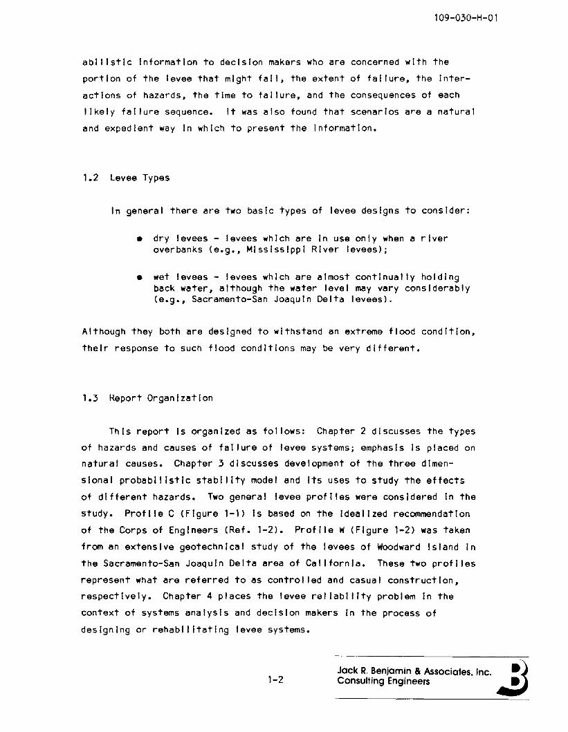
• dry levees - levees which are In use only when a riveroverbanks (e.g., MIssIssippI River levees);
• wet levees - levees whIch are almost contInually holdIngback water, although the water level may vary considerably(e.g., Sacramento-San JoaquIn Delta levees).
Although they both are desIgned to withstand an extreme flood condItion,
theIr response to such flood condItions may be very different.
1.3 Report OrganIzation
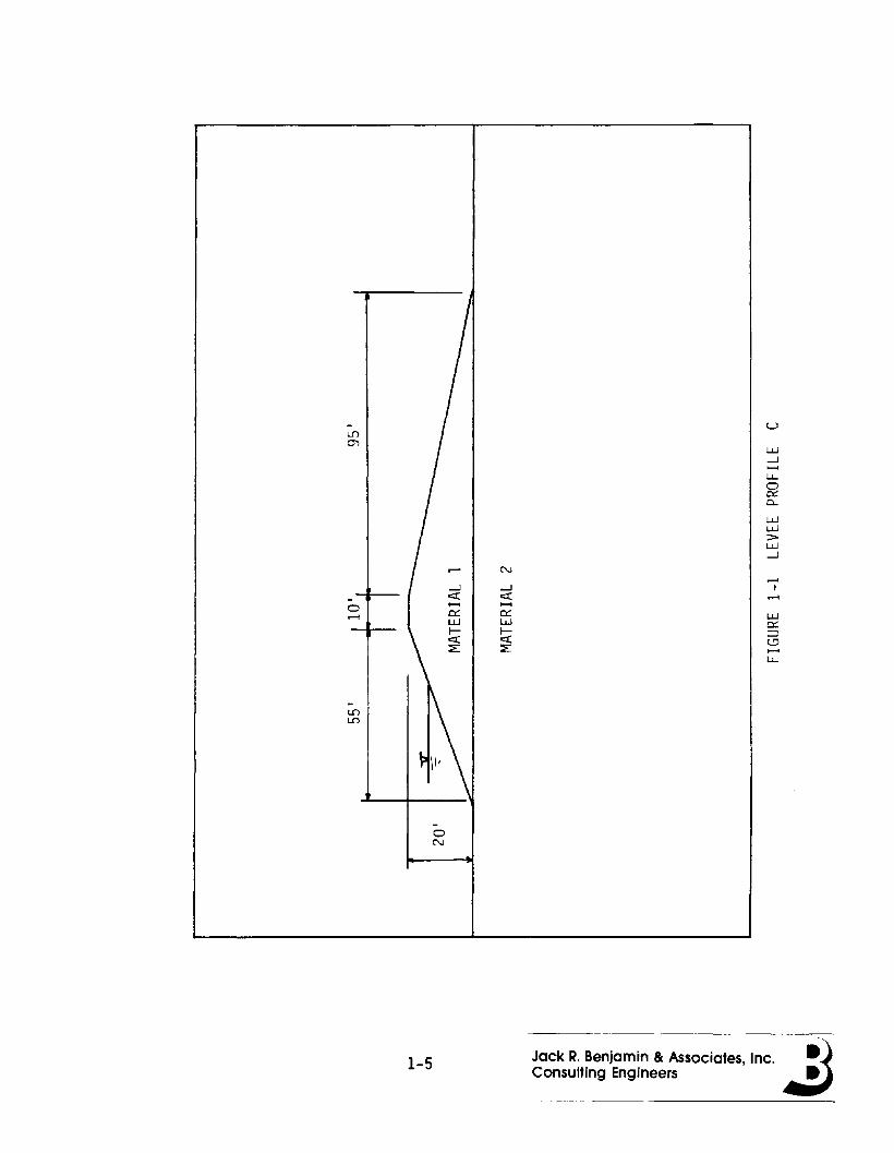
This report Is organIzed as follows: Chapter 2 discusses the types
of hazards and causes of fal lure of levee systems; emphasIs Is placed on
natural causes. Chapter 3 dIscusses development of the three dImen
sIonal probabilistic stability model and Its uses to study the effects
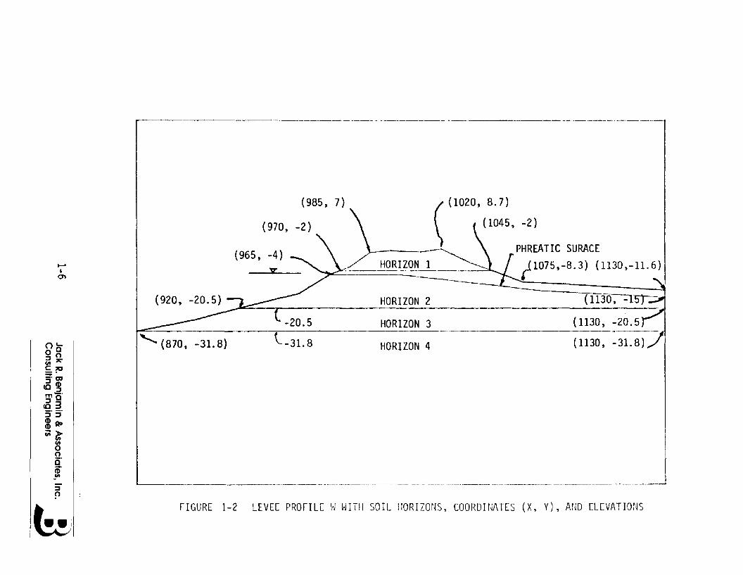
of dIfferent hazards. Two general levee profiles were considered In the
study. Profile C (Figure 1-1) Is based on the Idealized recommendatIon
of the Corps of Engineers (Ref. 1-2). Profile W(Figure 1-2) was taken
from an extensive geotechnical study of the levees of Woodward Island In
the Sacramento-San Joaquin Delta area of CalifornIa. These two profiles
represent what are referred to as controlled and casual construction,
respectively. Chapter 4 places the levee rei labilIty problem In the
context of systems analysIs and decIsion makers In the process of
designing or rehabilitating levee systems.
1-2Jack R. Benjamin Be Associates. Inc. ~)Consulting Engineers .,:J
109-030-H-01
1.4 References
1-1 Vanmarcke, LH., "Reliability of Earth Slopes," Journal of theGeotechnical Engineering Division, ASCE, Vol. 103, No. GT11,Nov. 1977, pp. 1247-1266.
1-2 Corps of Engineers, Design and Constuctlon of Levees, EM1110-2-1913, Dept. of the Army, March 1978.
1-3 Ang, A. H., and C. Cornell, "Reliability Bases of StructuralSafety and Design," Journal of the Structural Devlslon,ASCE, Vol. 100, No. ST9, Sept. 1974, pp. 1755-1769.
1-4 Baker, W. J., "Rei labIlity Analysis and Optimization of EarthSlopes," Notes of Massachusetts Institute of Technology SummerShort Course on Risk and Decisions In Geotechnical EngineerIng, Cambridge, Mass., E. H. Vanmarcke, ed., June 1976.
1-5 Ballgh, M., and A. AZzouz, "End Effects on Stability ofCohesive Slopes," Journal of the Geotechnical EngIneeringDivision, ASCE, Vol. 101, No. GT11, Nov. 1975, pp. 1105-1117.
1-6 Benjamin, J. R., and C. A. Cornel I, Probability, Statistics,and Decision for Clvl I Engineers, McGraw-HI I I Book Co., Inc.,New York, NY, 1970, pp. 251-253.
1-7 C. A. Cornell, "First-order Uncertainty Analysis of Sol IDeformation and Stability," Proc. 1st Int. Conf. onApplications of Statistics and Probability In Soil andStructural Engineer, Hong Kong University Press, Hong Kong,1971, pp. 129-144.
1-8 Lambe, T. W. and R. V. Whitman, Soil Mechanics, John WI leyand Sons, Inc., New York, NY 1969.
1-9 Vanmarcke, E.H., "Probabilistic Modeling of SoilProfiles," Journal of the Geotechnical Engineering Division,ASCE, Vol. 103, No. GT11, Nov., 1977, pp. 1227-1246.
1-10 Vanmarcke, E.H., "Probabilistic StabIlity AnalysIs of Earthslopes," Engineering Geology, Chapter 16, Elsevier ScientIficPublIshing Company, 1980, pp. 29-50.
1-11 Wu, T.H., "Uncertainty, Safety, and Decision In 5011 Engineering," Journal of the Geotechnical Engineering DivisIon,ASCE, Vol. 100, No. GT3, Mar., 1974, pp. 329-348.
1-12 Wu, T.H., and L.M. Kraft, "Safety Analysis of Slopes,"Journal of the Soil Mechanics and Foundation DivisIon, ASCE,Vol. 96, No. 5M2, Mar., 1970, pp. 609-630.
1-3Jack R. Benjamin & Associates, Inc. ~)Consulting Engineers ~

109-030-H-01
1-13 Yuceman, M., W. Tang, and A. Ang, "A Probabilistic Study ofSafety and Design of Earth Slopes," Structural Research SeriesNo. 402, University of Illinois, Urbana, II I., July, 1973.
1-14 Yucemen, M.S. and E.H. Vanmarcke, "Seismic Rellabl Ity Analysisof Earth Slopes," ProceedIngs Fourth International Conferenceon Applications of Statistics and ProbabilIty In Soil andStructural EngIneerIng, University dl Flrenze (Italy),Pltagora Edltrlce, 1983.
1-15 Lumb, P., "Application of Statistics In 5011 Mechanics," SoilMechanics - New Horizons, Butterworth & Co., London, England,1974, pp. 44-111.
1-4
Jack R. Benjamin & Associates, Inc. ~)Consulting Engineers ~
-L{')
0'>
r- N
...J ...J
- e::( e::(
0 ~ ~
0::: 0:::......LJ.J LJ.Jl- I-e::( e::(::E: ::E:
-L{')L{')
~ \1-
-0N
u
LJ.J...J~
l..L..
~Q..
LJ.JLJ.J>LJ.J...J
LJ.J0:::=:>o~
l..L..
1-5 Jack R. Benjamin & Associates, Inc.Consulting Engineers
.-._------------._-- -~ _._--------_ .. ---------------- ------·-·----·---·-1
-_._...._-.._--- --_._----_.--------
HORIZON 4
(
(l020, 8.7)
I (1045, -2)
\.- _~, PHREATIC SURACE
~_~ HORIZ~~ ~ ~1075,-8.3) (1130,-11.6)
---L...-20.5
l-31.8
".
(985, 7)
(970, -2)
(965, -4)
HORIZON 2_....k"'"":~_-.-.________ _ _HORIZON 3
""" (870, -31. 8)
::::J~
nc0°::::JOCIl'1':'
£?O=m::::JeD
CC::::JmO'::::J 3~'5'eD RDeDC;;~
CIlooi5'
m
~
Ien
6FIGURE 1-2 LEVEE PROFILE 1,1 WITH SOIL HORIZONS, COORDUiATES (X, Y), AND ELEVATIONS
109-030-H-Ol
2. HAZARDS CAUSING FAILURE
2.1 Types of Failure
In general, a levee system Is said to have failed when the
protected area Is flooded as a result either of water crossing the line
of the levee from the riverside or water not being able to cross from
the landslde. The former failure can occur by overtopping from the
riverside of the levee or by structural failure of the levee from hydro
static pressure, piping, erosion, or earthquake. The latter fal lure can
occur when accessorial facilities (I.e., pipes, pumps, ponds, and
valves) fal' to prevent flooding from Interior drainage or through
seepage.
2.1.1 Overtopping
Overtopping Is caused by a flood stage which Is higher than the
levee crest heIght. Levee crest heights are usually designed to with
stand specified peak flood stage plus a margin of safety which Is based
both on hydrologic and hydraulic considerations. However, what the
designed crest height Is and what the actual height Is may differ con
siderably over time due to subsidence, erosion, compaction, etc. Levees
which are poorly maintained wi II be more susceptible to overtopping over
a period of time, because crest heights will decrease due to one or a
combination of the above causes.
Flood stages for a given return period are uncertain. Hydrologic
parameters used to predict discharge are based on limited historic
records or on no historic data. Therefore, a level of uncertainty
exists In these parameters. In addition, uncertainty exists In the
2-1Jack R. Benjamin & Associates, Inc. ~)Consulting Engineers .:J
109-030-H-Ol
hydrology of the flood. Although standard hydraul Ie techniques exIst to
predIct flood profiles for gIven dIscharges, they are IdealIzations of a
real world phenomenon whIch changes In tIme.
2.1.2 StabilIty
The stabIlity failure of a levee at some location along the length
Is a problem In contInuum mechanics, since the center of fal lure may
occur anywhere along a reach, and the failure length can be almost any
value withIn practical limIts. In addition, the fal lure surface or zone
of slippage may be anyone of an InfInIte number of possibilItIes
although failures may wei I be associated wIth a zone of weakness or a
weak seam between two layers. FIgure 2-1 I I lustrates the above three
random variables, and IndIcates the contInuum nature of each. To compl 1
cate the problem, the possible centers of faIlure, the lengths of
fal lure, and the zones of slIppage are all correlated to some degree
with each other.
The conventional practIce In evaluatIng exIstIng levees Is to look
first at what are thought to be the weakest cross-sectIons, at least
from the point of vIew of geometry. Soil samples are taken at these
"weak" points and mInImum factors of safety computed for a two
dImensIonal sl Ice of the levee. In addItion, a few "typical"
cross-sections may also be evaluated. However, a systematIc attempt Is
not made to fInd cross-sectIons with low soil strength and the
three-dimensional aspects of the problem are not considered.
The failure problem of levees Is analogous to the problem of a long
rod subjected to an axIal load F. The rod has a cross section, A, whIch
varIes randomly along the length, and has a unIt strength, fy, whIch
also varIes randomly along the length. The combInatIon of geometry and
strength Is then the determInIng factor of whether the rod yields or not
at any poInt, x. The probabIlIty of yield for the entIre rod length,
given the load F, Is then:
2-2 Jack R. Benjamin & Associates, Inc. ~)Consulting Engineers .:.J
109-030-H-Ol
PF = Prob [F ~ Min (A(X)fy(X))]for all x
If the load F Is also a random function of x (disregarding the
Issue of equilibrium) then the probability of yield becomes:
PF = Prob [1 ~ Minfor all x
( A(x)f(x) )]F{x) .
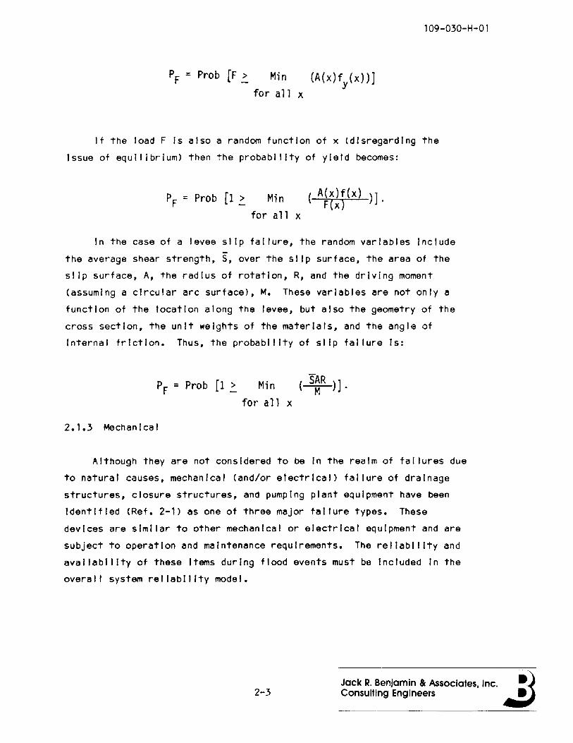
In the case of a levee slip fal lure, the random variables Include
the average shear strength, S, over the slip surface, the area of the
slip surface, A, the radius of rotation, R, and the driving moment
(assuming a circular arc surface), M. These variables are not only a
function of the location along the levee, but also the geometry of the
cross section, the unit weights of the materials, and the angle of
Internal friction. Thus, the probability of slip fal lure Is:
PF = Prob [1 ~ Min ( S~R )].for all x
2.1.3 Mechanical
Although they are not considered to be In the realm of fal lures due
to natural causes, mechanical (and/or electrical) fal lure of drainage
structures, closure structures, and pumping plant equipment have been
Identified (Ref. 2-1) as one of three major failure types. These
devices are similar to other mechanical or electrical equipment and are
subject to operation and maintenance requirements. The reliability and
availability of these Items during flood events must be Included In the
overall system reliability model.
2-3Jack R. Benjamin & Associates, Inc. ~)Consulting Engineers .:J

109-030-H-Ol
2.2 Causes of Failure
Many failures have been associated with circumstances or mechanisms
outside conventional theoretical analysis. Most of these fal lures occur
not because of the Inadequacies In the state of the art, but because of
oversights that could have been avoided, or poorly understood phenom
ena. The probabilities of failure of levees could decrease If the
causes not easily analyzed were dealt with rationally by acknowledging
and quantifying the uncertainty Involved.
2.2.1 Flood Depth
Although there Is no consistent rational basis for doing so, most
levee systems In the United States are designed to withstand the 100
year return period flood stage without overtopping. However, the
100-year return period flood cannot be predicted with certainty. This
Is due to a number of factors. The first Is the definition of the
100-year flood. One hundred years Is the return period or recurrence
Internal for this flood level and Is defined as the average number of
years within which this event will be equaled or exceeded. Since It Is
only the average number of years, there Is approximately a 33 percent
chance that the "true" number of years Is less than 100.
Other factors which must be considered in predicting a given flood
stage are hydrologic and hydraulic uncertainty. Hydrologic design Is
generally based on past events and any attempt to predict future events
must be based on probability. Haan (Ref. 2-2) has pointed out the the
hydrologic probability model may be rainfall Input to a hydraulic model,
to predict runoff, or a flood level frequency curve based on historical
stream flows. In the former, not only is there hydrologic uncertainty,
but hydraulic modeling uncertainty as well.
2-4Jack R. Benjamin & Associates, Inc. ~)Consulting Engineers .:J
109-030-H-Ol
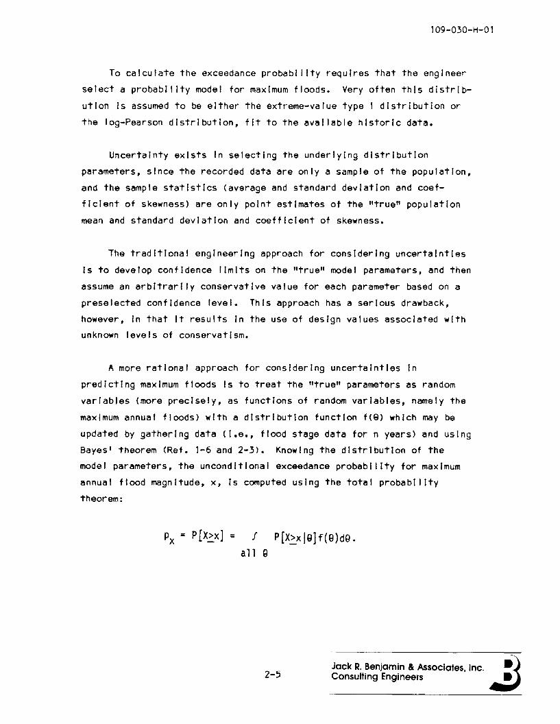
To calculate the exceedance probability requires that the engineer
select a probability model for maximum floods. Very often this distrib
ution Is assumed to be either the extreme-value type I distribution or
the log-Pearson distribution, fit to the available historic data.
Uncertainty exists In selecting the underlying distribution
parameters, since the recorded data are only a sample of the population,
and the sample statistics (average and standard deviation and coef
ficient of skewness) are only point estImates of the "true" population
mean and standard deviation and coefficient of skewness.
The traditional engineering approach for considering uncertainties
Is to develop confidence limits on the "true" model parameters, and then
assume an arbitrarIly conservative value for each parameter based on a
preselected confIdence level. This approach has a serIous drawback,
however, In that It results In the use of desIgn values associated with
unknown levels of conservatism.
A more rational approach for considering uncertainties In
predicting maximum floods is to treat the "true" parameters as random
variables (more precisely, as functions of random variables, namely the
maximum annual floods) with a distribution function f(8) which may be
updated by gathering data (i.e., flood stage data for n years) and using
Bayes' theorem (Ref. 1-6 and 2-3). Knowing the dIstrIbutIon of the
model parameters, the unconditional exceedance probabilIty for maximum
annual flood magnitude, x, Is computed usIng the total probability
theorem:
Px = P[~x] = J P[X>xjQ]f(Q)dQ.all Q
2-5Jack R. Benjamin & Associates, Inc. ~)Consulting Engineers .:J
109-030-H-01
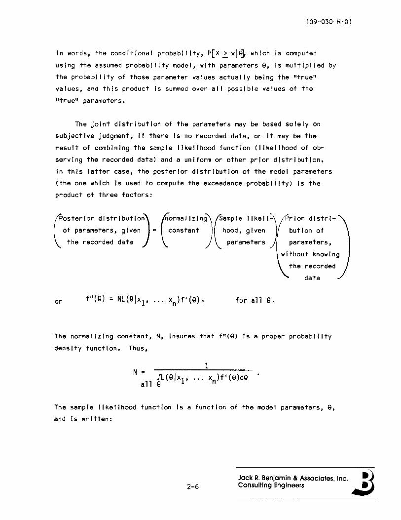
In words, the conditional probability, p[x ~ xl 91 which Is computed
using the assumed probability model, with parameters 9, Is multiplied by
the probab III ty of those parameter va lues actua I IY be Ing the "true"
values, and this product Is summed over al I possible values of the
"true" parameters.
The joint distribution of the parameters may be based solely on
subjective judgment, If there Is no recorded data, or It may be the
result of combining the sample likelihood function (likelihood of ob
serving the recorded data) and a uniform or other prior distribution.
In this latter case, the posterior distribution of the model parameters
(the one which Is used to compute the exceedance probability) Is the
product of three factors:
(
Osterlor dlstrlbutlO)of parameters, given =
the recorded data(
ormaIIZlnj(amPle Ilkell)constant hood, given
parameters
rlor distri
bution of
parameters,
without knowing
the recorded
data
or for all Q.
The normalizing constant, N, Insures that f"(9) Is a proper probability
density function. Thus,
The sample likelihood function Is a function of the model parameters, 9,
and Is written:
2-6Jack R. Benjamin Be Associates, Inc. ~)Consulting Engineers .,:J

109-030-H-O 1
n'IT f(X; = x;IQ).
;=1
where f(XIIS) Is the assumed underlying distribution of maximum annual
floods. For example, If the distribution were assumed to be extreme
value type I (Gumbel), then the likelihood function would be written:
n= 'IT aexp{-a(x.-u) - exp[-a(x,'-u)]},
;=1 '
where Q = 1.282 / q X' and u = mX - O.450 q X (Ref. 2-4). The model
parameters, mX and q X are uncerta In.
Assuming a log-Pearson distribution, there would be three model
parameters to cons Ider, my, q y, and "Yy (coef f Ic Ient of skewness),
where Y = m(X), and X Is the maximum annual flood. The sample
likelihood function for a log-Pearson probability distribution Is
written:
where
for c < y.< 00- ,_00 < y.< c,-
(8 > 0) •(8 < 0) •
2-7Jack R. Benjamin & Associates, Inc. ~)Consulting Engineers .:J
109-030-H-Ol
and r :·)Is the gamma function.
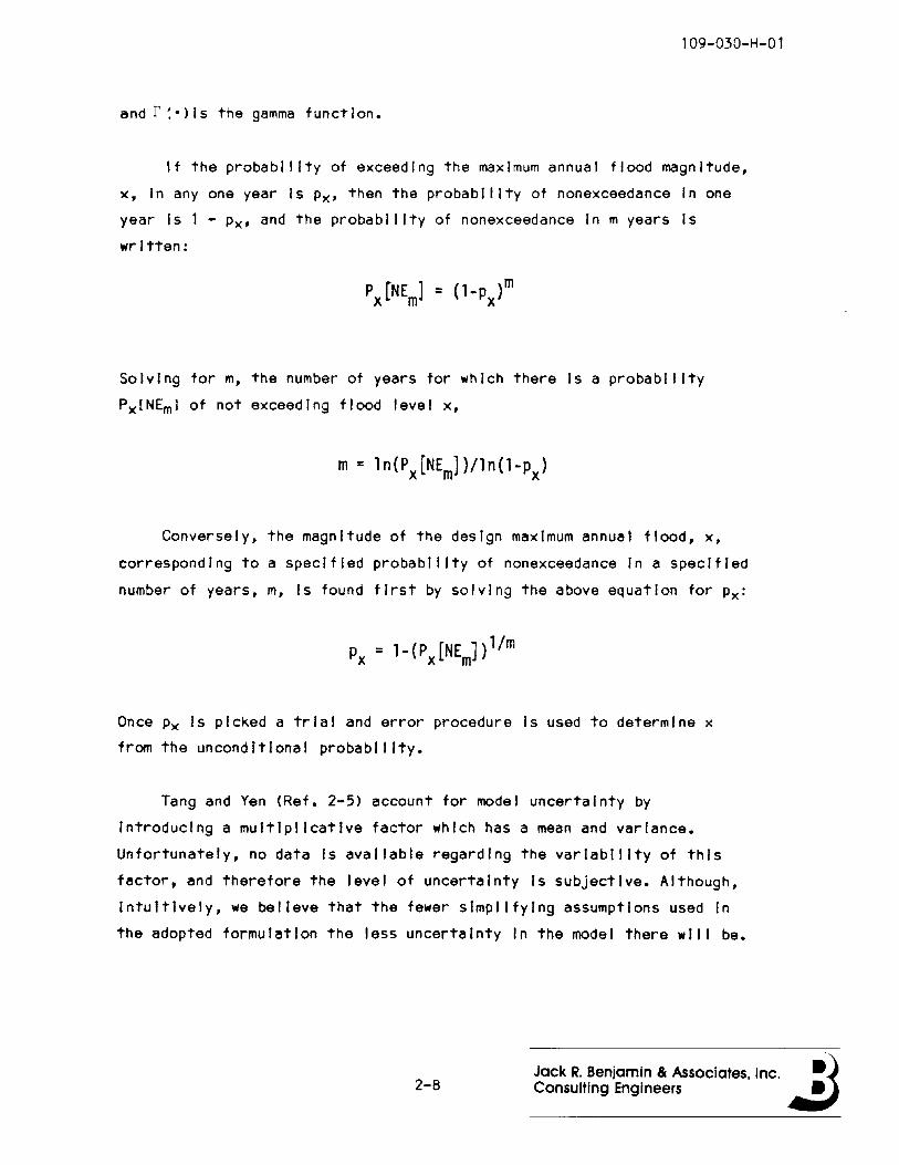
If the probability of exceedIng the maximum annual flood magnitude,
x, In anyone year Is Px' then the probability of nonexceedance In one
year Is 1 - Px' and the probability of nonexceedance In m years is
written:
Solving for m, the number of years for which there is a probability
PxlNEml of not exceeding flood level x,
m= In{Px[NE ])/In{l-p )m x
Conversely, the magnitude of the design maximum annual flood, x,
corresponding to a specified probability of nonexceedance In a specified
number of years, m, Is found first by solving the above equation for Px:
p =l-{P [NE J)l/mx x m
Once Px Is picked a trial and error procedure Is used to determine x
from the unconditional probability.
Tang and Yen (Ref. 2-5) account for model uncertainty by
Introducing a multiplicative factor which has a mean and variance.
Unfortunately, no data Is available regarding the variability of this
factor, and therefore the level of uncertainty is subjective. Although,
IntuItively, we believe that the fewer simplifying assumptions used In
the adopted formulation the less uncertainty In the model there will be.
2-8Jack R. Benjamin & Associates, Inc. ~)Consulting Engineers .:J
109-030-H-Ol
Uncertainty In flood discharges can be translated Into
corresponding uncertainty In flood stage using standard hydraul Ie tech
niques. Stream reaches with a high degree of hydraul Ie sensitivity
<I.e., relatIvely great changes In stage results from a relatIvely smal I
change In dIscharge) wll I have a greater tendency for levee overtopping
than less sensitive ones.
Other factors that must be assessed In the evaluation of the
hydraulic uncertaInty are the potentIal and magnItude of debrIs or
sedIment accumulatIon or Ice jammIng during the dIscharge event.
Sources of debrIs, sedIment, and Ice In upstream areas should be con
sidered, as well as any historical evIdence of Ice or debris blockage or
sediment depositIon. The behavior of such materIals wIthin the leveed
reach, and partIcularly at bends or constrictions, must be consIdered.
Flood stages for a given flow can change over tIme due
of factors, and any change wI II alter the hydrologIc rIsk.
affectIng flood stage Include:
to a varIety
Changes
• Increased land use change that results In Increased runoff
volumes, shorter tImes of concentration, and greater peak dis
charges for events havIng the same meteorologIcal
characteristIcs;
• removal of natural valley storage and conveyance due to excess
encroachment In floodplaIns, Including construction of levee
systems, resulting In higher stages and discharges;
• construction of reservoirs that modify the flows so that
historical records cannot be used for current rIsk assessment
wIthout hydrologIc reanalysis;
2-9 Jack R. Benjamin & Associates, Inc. ~Consulting Engineers .:J
109-030-H-01
• changes to river bed or bank geomorphology or vegetative cover
that significantly alter stage-discharge relationships and flood
elevations.
2.2.2 Flood Exposure
Even though levees are generally designed such that the probability
of overtopping Is smal I, levees exposed to flood stages lower than the
crest for long durations are susceptible to damage and even failure due
to loss of stability, underseepage, sand bolls, and wave erosion.
Bogardl (Ref. 2-6) Introduced the concept of "flood exposure" to take
account of the combined effects of flood stage and duration on levee
systems. He defined flood exposure as the area under the hydrograph of
high water stages exceeding a specified limit, usually the toe elevation
(for dry levees). At times of high water stages the following adverse
phenomena have been observed along flood levees:
• saturation, loss of stability;
• underseepage and leakage;
• boll formation;
• wave erosion.
Saturation occurs generally by seepage below and laterally through the
levee body by Increased hydraulIc pressure. RespondIng on the relative
permeabll Itles of the levee material and substrata, seepage wi I I occur
either more rapidly through the levee material, In which case stability
Is weakened and leakage Is common, or through the substrata, In which
case underseepage and boll formation with possible crevasslng on the
landslde of the levee Is likely.
Flood exposure Is the function of two random variables, flood stage
and duration. To determine the resistance to such a load, It Is neces
sary to perform stability analyses In whIch slope stability Is
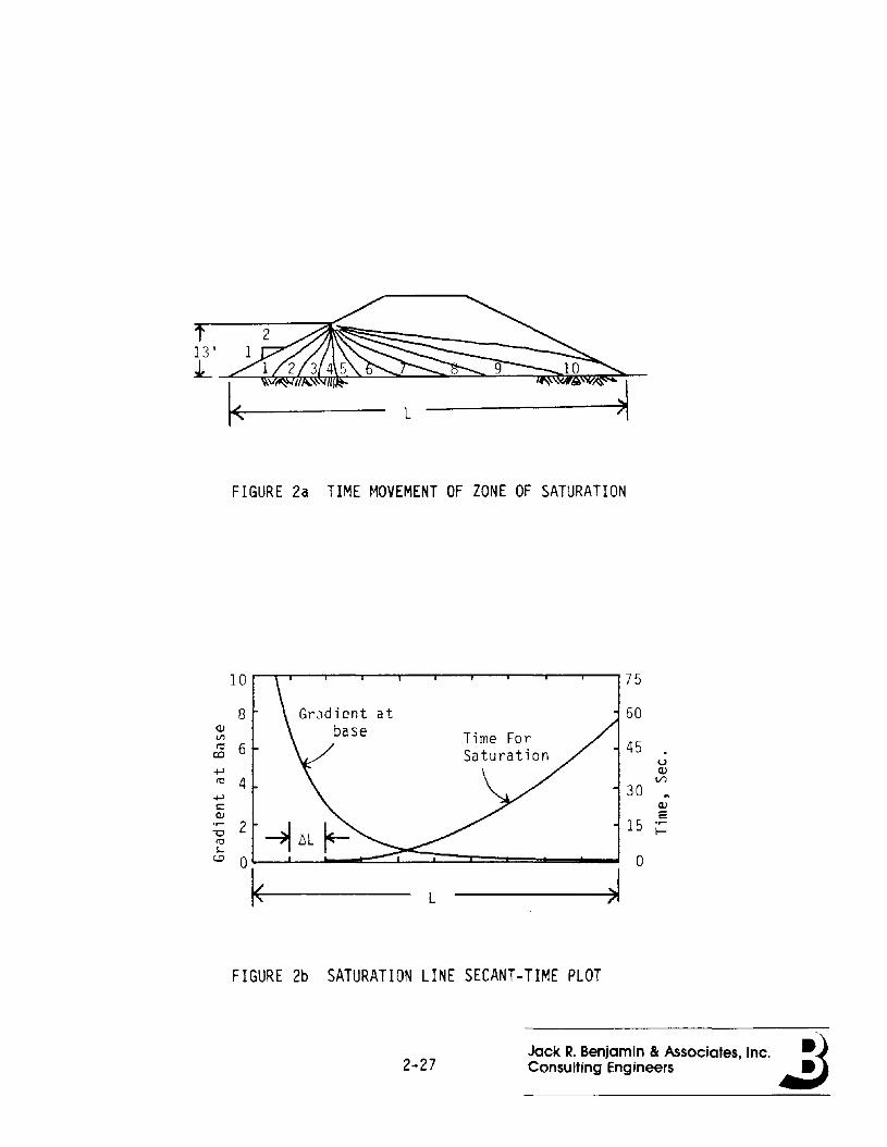
calculated for a time dependent zone of saturation. Determining the
2-10Jack R. Benjamin & Associates, Inc. ~)Consulting Engineers .:J
109-030-H-O 1
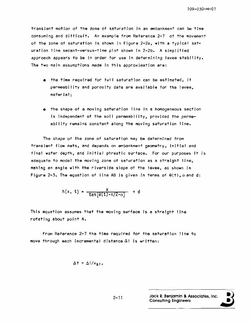
transient motion of the zone of saturation In an embankment can be time
consuming and difficult. An example from Reference 2-7 of the movement
of the zone of saturation Is shown In Figure 2-2a, with a typical sat
uration line secant-versus-tlme plot shown In 2-2b. A simplified
approach appears to be In order for use In determining levee stability.
The two main assumptions made In this approximation are:
• the time required for ful I saturation can be estimated, If
permeability and porosity data are available for the levee,
material;
• the shape of a moving saturation line In a homogeneous section
Is Independent of the soil permeability, provided the perme
ability remains constant along the moving saturation line.
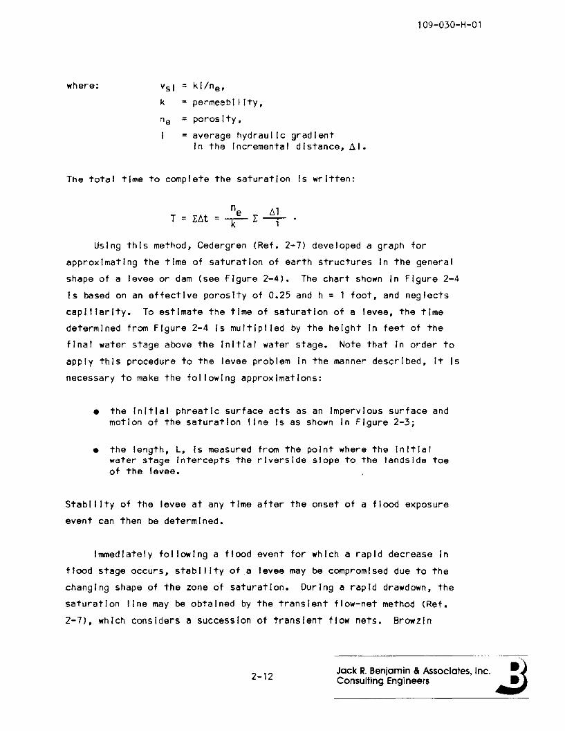
The shape of the zone of saturation may be determined from
transient flow nets, and depends on embankment geometry, Initial and
final water depth, and Initial phreatic surface. For our purposes It Is
adequate to model the moving zone of saturation as a straight line,
making an angle with the riverside slope of the levee, as shown In
Figure 2-3. The equation of line AS Is given In terms of SCt>,aand d:
h(x, t) = tan[Q(tJ-n/2-a)- + d
This equation assumes that the moving surface Is a straight line
rotating about point A.
From Reference 2-7 the time required for the saturation line to
move through each Incremental distance 61 Is written:
6t = 61/vs l'
2-11 Jack R. Benjamin & Associates, Inc. ~)Consulting Engineers .:J
where: vsI = klIne'
k = permeabl'Ity,
ne = porosity,
= average hydraulic gradientIn the Incremental distance, 61.
109-030-H-01
The total time to complete the saturation Is written:
ne 111T = r~t =-k--- r --,-
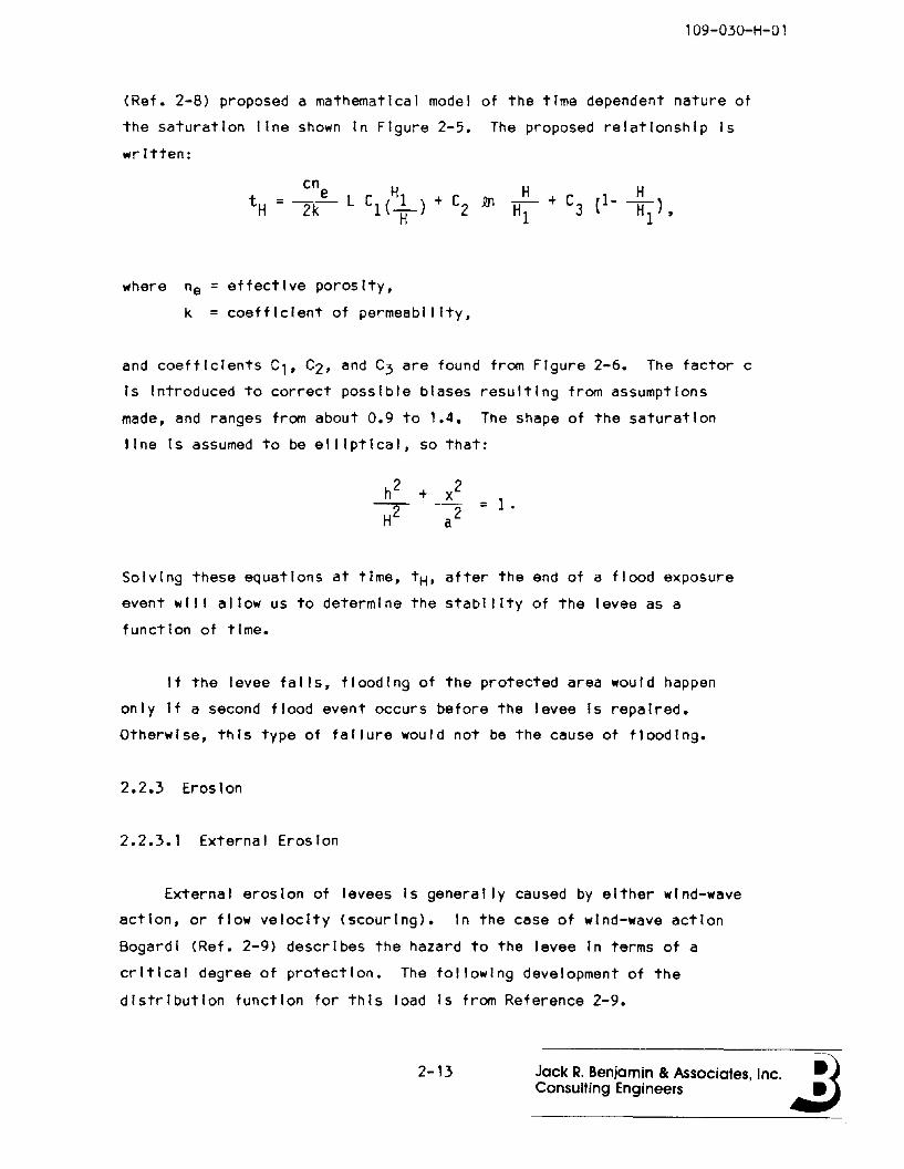
Using this method, Cedergren (Ref. 2-7) developed a graph for
approximating the time of saturation of earth structures In the general
shape of a levee or dam (see Figure 2-4). The chart shown In Figure 2-4
Is based on an effective porosity of 0.25 and h = 1 foot, and neglects
capillarity. To estimate the time of saturation of a levee, the time
determined from Figure 2-4 Is multlpl led by the height In feet of the
final water stage above the Initial water stage. Note that In order to
apply this procedure to the levee problem In the manner described, It Is
necessary to make the following approximations:
• the Initial phreatic surface acts as an Impervious surface andmotion of the saturation line Is as shown In Figure 2-3;
• the length, L, Is measured from the point where the Initialwater stage Intercepts the riverside slope to the landslde toeof the levee.
Stability of the levee at any time after the onset of a flood exposure
event can then be determined.
Immediately following a flood event for which a rapid decrease In
flood stage occurs, stability of a levee may be compromised due to the
changing shape of the zone of saturation. During a rapid drawdown, the
saturation line may be obtained by the transient flow-net method (Ref.
2-7), which considers a succession of transient flow nets. Browzln
2-12 Jack R. Benjamin Be Associates, Inc. ~)ConSUlting Engineers Jt:J
109-030-H-0 1
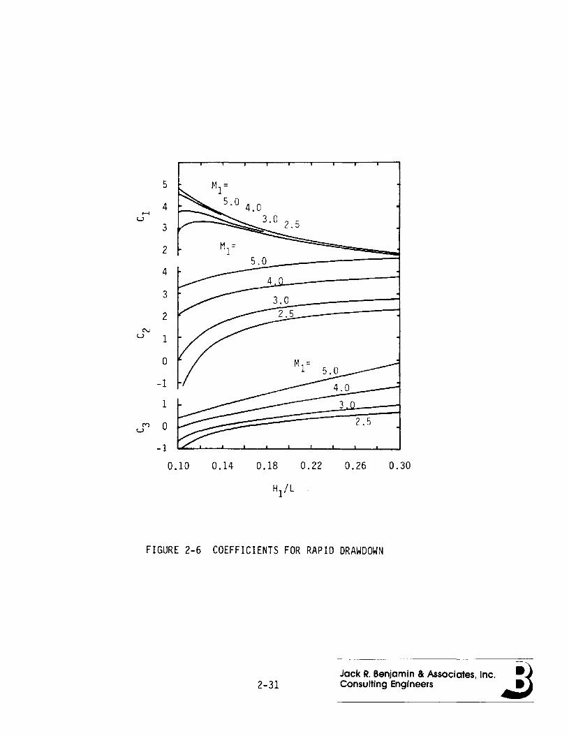
(Ref. 2-8) proposed a mathematical model of the time dependent nature of
the saturation line shown In Figure 2-5. The proposed relationship Is
written:
where ne = effective porosity,
k = coefficient of permeability,
and coefficients C" C2, and C3 are found from FIgure 2-6. The factor c
Is Introduced to correct possible biases resulting from assumptions
made, and ranges from about 0.9 to '.4. The shape of the saturation
line Is assumed to be elliptical, so that:
+ /-- = 1.
a2
Solving these equations at time, tH, after the end of a flood exposure
event wll I allow us to determine the stability of the levee as a
function of time.
If the levee falls, flooding of the protected area would happen
only If a second flood event occurs before the levee Is repaired.
Otherwise, thIs type of failure would not be the cause of flooding.
2.2.3 Erosion
2.2.3.1 External Erosion
External erosion of levees Is generally caused by either wind-wave
action, or flow velocity (scouring). In the case of wind-wave action
Bogard I (Ref. 2-9) describes the hazard to the levee In terms of a
critical degree of protection. The following development of the
distribution function for this load Is from Reference 2-9.
2-13 Jack R. Benjamin & Associates, Inc. ~)Consulting Engineers .:J
109-030-H-01
The flood stage, h1, and the additional wave effect, hm, result In
the total height, hT. The value, hm, Is composed of the wave height due
to wind plus run-up on the slope. The task Is to determl ne the
distribution function of the random variable, hT, where:
The model assumes that the random variables, h, and hm, are Independent.
The distribution function of the annual highest stages, h" Is assumed
to be known and available from characteristic stream gauges. For the
calculation of wave effect, hm, the basic relationship Is the fol lowing:
h = f(Di , Vi' tana, cosS)IDi '
(See Figure 2-7)
Therefore, referring to the notation given In Figure 2-7, the wave
effect on the cross section due to the wind having direction 5 depends
on the corresponding fetch length, DI, wind velocity, VI, angle of levee
slope, and the angle between the tangent of the levee and the examined
direction. For the sake of simplicity only the most Important variables
have been mentioned.
In practice, the Inundation area along the flat-slope reaches of
large rivers Is several kilometers wide. For these conditions the flood
wave peak may last several days and during this period the water level
changes very little. This justifies approximating the stochastic flood
wave hydrograph by a constant peak value of random duration. Obviously,
the highest waves occurlng during this period may create the critical
erosion situation.
From past records covering several years of wind measurements of
the meteorological stations situated In the vicinity of the Investigated
levee section, maximum wind velocities for different directions (for
Instance for the eight main directions) and for different durations
could be used. According to the above relationship, the maximum wave
2-14 Jack R. Benjamin & Associates, Inc. ~)Consulting Engineers .:J
109-030-H-01
effect for different directions can be calculated for the critical
period. The highest of these gives one sample element of hm• Naturally,
the probability of the yearly hIghest waterlevels occurring In different
months of the year should be considered and the distribution of the wave
effect, corresponding to the monthly critical period should be weighted
with the appropriate probabilities.
Other types of external erosion are caused by excessive stream
velocity, unstable streambed, and channel configurations which contri
bute to water flows Impinging on levees and causing scour. When bank
protection Is subjected to stable currents, then surface erosion wll I
occur when the tractive force produced by flow velocity exceeds the
critical tractive force for levee surface protection. In addition,
waves caused by unstable streambed formations near the levee, or flow
Impingement on the levee produce uplIft pressures In combInation with
stream velocIty and can cause surface erosion when tractIve forces are
smaller than critIcal. Consequently, when bank protection Is designed
for flow velocIty alone and signIfIcant waves occur along the bank,
surface erosIon may occur for flows substantially less than the design
flow.
Scour may be the result of unforeseen cIrcumstances. An example Is
gIven In Reference 2-10, whIch describes a levee failure caused by
scour. Naturally carrIed sediments were deposited upstream of a channel
Inlet, and, subsequently, sediment-free water was delivered to a rather
steeply sloped reach. This was responsIble for general streambed de
gradation downstream of the channel. In addItion, channel meandering
resulted In flow Impingement on the levee causIng deep scour at the
rIverside toe. The angle of Implngment was estImated to be
approximately 25 degrees.
Wide streams whIch are free to meander wll I have poInts and angles
of ImpIngement whIch are uncertaIn and should be addressed In desIgn
usIng probabIlities.
2-15 Jack R. Benjamin & Associates, Inc. ~)Consulting Engineers .:J
109-030-H-Ol
2.2.3.2 Internal ErosIon
Turnbul I and Mansur (Ref. 2-11) made the followIng observatIons
regardIng underseepage and sand bolls:
• sand bolls are the result of excessIve hydrostatIc pressure andseepage through deep pervIous strata underlyIng levees severIty Is dependent upon the water head, source of seepage,pervIousness of substratum, and characterIstIcs of the landsldetop stratum;
• there Is a posItIve correlatIon between surface geology andlocatIon and occurrence of sand bolls;
• seepage flow and hydrostatIc heads landward of a levee can beestImated theoretIcally, from pIezometrIc data, and a knowledgeof the foundatIon condItIons.
FaIlure due to seepage Is progressIve. Seepage under or through a
levee applIes pressure to the soIl partIcles, and If the pressure Is
great enough to carry or 11ft the partIcles, a sand boll or pIpIng of
materIals from below or wIthIn the levee occurs. PIpIng, or sand bol l
Ing, does not In Itself constItute faIlure of the levee, however. EIther
slope InstabilIty or the phenomenon of crevasslng must occur as a result
of pIpIng In order that a levee fall from seepage. Turnbul I and Mansur
(Ref. 2-11) made the statement that "although a number of levee crevas
ses have occurred as a result of crItIcal substratum pressures and
concentrated seepage In the form of sand bolls or pipIng It Is practIc
ally ImpossIble to predIct." If, however, data related to underseepage
and crevasslng does exIst, It appears possIble to predIct the occurrence
of crevasslng probablilstlcally, gIven the occurrence of pIpIng or sand
boll s.
A pre-flood event condItIon whIch also Influences the occurrence of
pIpIng or boIlIng Is the amount and avaIlabIlIty of substratum storage
capacIty on the landslde of the levee. If a large storage capacIty Is
avaIlable and a flood occurs, there may be a lag tIme of several days
before seepage problems occur, sImply because the substratum storage
2-16 Jack R. Benjamin & Associates, Inc. ~)ConSUlting Engineers .:J

109-030-H-Ol
volume must be fll led before the pressure under the top stratum can be
built up. By that time the flood may have dissipated. On the other
hand, If the storage volume Is already fll led or nearly fll led by pre
vious storms, seepage related problems may be coincident with the
present flood event.
Seepage flow and hydrostatic heads landward of a levee can be
estimated from theoretical considerations, piezometric data and know
ledge of the underlying strata. Obviously the accuracy of such methods
dependens on the degree of uncertainty In the parameters used In the
formulations and the sensitivity to those parameters excluded.
Not al I factors which Influence the seepage flow and pressure lend
themselves to theoretical analysis. Some of these factors Include
stratification of the foundation, lense deposits, and nonunlformlty of
the top stratum. However, some of the Influences which may be evaluated
are as follows:
• semi-Infinite unconfined aquifer (Ref. 2-12) - for a sudden rise
In the water stage from an Initial steady state level of HO to
Hl (See Figure 2-8a), the change In head at a point x away from
the river bank Is written:
2 2 (2 2) (xh (x, t) = HO+ H1-HO erfc ------2M
where: D = (kf-h)/E,
kf = horizontal permeability of aquifer,
h = 0.5 IHO + h(x,t»),
E = specific yield of aquifer,
and erfc (.) Is the complementary error function;
2-17Jack R. Benjamin Be Associates, Inc. ~)Consulting Engineers .:J
109-030-H-Ol
• finite unconfined aquifer (Ref. 2-12) - for a sudden rise In the
water stage from an Initial steady state level of HO to H1 In
the river (See Figure 2-8b), the change In head at a point x
away from the river bank Is written:
2( ) 2 2 2 (Xl n[ 2Ln+xh x, t = HO+(H1-HO) {r (-1) erfc( 2IDtn = 0
+ erfc( 2Ln+2L-x )J}2li'Dt •
where L Is the horizontal distance from the river bank to the
barrier boundary.
Another cause of Internal erosion, and one which does not readily
lend Itself to analytical evaluation, Is animal burrowing and activity
(Ref. 2-13). Burrows of animals (squirrels, beavers, muskrats) In
levees may Increase seepage and provide a path for water to flow during
high water stages.
2.2.4 Settlement and Subsidence
Levees depend to some extent on freeboard to compensate for the
lowering of crest height due to settlement and subsidence. It was
pointed out In Reference 2-1 that levees with minimal or no compaction,
or where embankment or foundation materials are undrained or composed of
materials of high compressibility, wi II often experience a significant
amount of postconstructlon settlement. This settlement can result In
losses of freeboard as much as 15 percent of the total levee height.
These settlement losses wi I I contribute to Increased chances of
overtopping and/or stability problems.
Another very Important hazard which causes failure of some types of
levees (particularly levees protecting highly organic lands used for
agriculture) Is subsidence of the levee and protected areas. In one
study of the Sacramento-San Joaquin Delta area (Ref. 2-14), subsidence
rates for Islands and tracts protected by levees Is as much as three
2-18 Jack R. Benjamin & Associates, Inc. ~)Consulting Engineers .:J
109-030-H-Ol
Inches per year. These subsidence rates have resulted In protected
lands being below normal water levels by as much as 10 to 20 feet,
thereby Increasing the pressure on levees significantly.
Primary causes of subsidence were found to be soli oxidation and
shrinkage. Additional causes, some of which may be substantial In
localized areas, are wind erosion, burning, man-caused compaction,
removal of soil, geologic (tectonic) subsidence and withdrawal of gas or
ground water.
2.2.5 Earthquake
Earthquake ground motion can cause sliding failure either as a
result of the change In material mechanical properties by liquefying,
and/or an Increase In loading by Imposing an addition driving force In
the horizontal direction.
Other possible Impacts on levees resulting from earthquake ground
shaking Include (Ref. 2-15):
• compaction and settlement of levees or foundations;
• lateral spreading of levees or foundations;
• slumping;
• ground cracking;
• lurching of levees;
• erosion or overtopping by earthquake generated waves (seiches).
2-19 Jack R. Benjamin & Associates, Inc. ~)Consulting Engineers .:J
109-030-H-01
The potential hazards caused by earthquakes are greatest during high
water when levees are already under high stress. The likelihood of such
a combination of events Is greatest for wet levees In areas such as the
Sacramento-San Joaquin Delta. However, Mississippi River levees during
flood season are also vulnerable for extended periods of time.
2.2.5.1 Inertia Load
The acceleration of the soil In an earthquake Is another potential
source of fal lure. Conventionally, the soil Is simply assumed to be
accelerated and this Is an added driving force. With levees, the pos
sibility of site amplification and the Influence of water entrapped In
the levee must be considered. The site amplification analysis requires
a first mode approximation for the levee as a shear beam above the sol I
level where the ground motion Is assumed Imposed. Levee profiles wi II
In general Involve relatively long periods for casual construction, such
as found In the Sacramento-San Joaquin Delta. Engineered fll Is, such as
earth dams, produce stiffer materials and thus shorter periods along
with decreased ability to deform without cracking.
2.2.5.2 Liquefaction
At this time, the state of knowledge of liquefaction does not al low
the definition of the volume of material that loses Its strength through
Increase In pore pressure. Hydraulically placed sands, for example, can
lose their strength (friction) with a sufficient level or duration of
vibration or both. One measure of the potential to fall Is the number
of blow counts It takes to move a standard probe one foot In the field.
In effect, If the soli Is highly likely to liquify, the blows of the
sampling device on the sol I wi I I Indicate this potential and the number
of blows per foot will be sma I I.
2-20Jack R. Benjamin & Associates, Inc. ~)Consulting Engineers .:J
109-030-H-01
Liquefaction Is an "either-or" phenomenon; either It does or does
not occur for a given earthquake motion at a given site. Apparently,
only sandy soils are prone to liquefaction, and It must, therefore, be
determined whether a site has susceptible soil.
Seed and Idrlss (Ref. 2-16) and more recently Seed, Idrlss, and
Grango (Ref. 2-11) presented a simplified procedure for evaluating the
liquefaction potential for sand deposits. The procedure expresses the
ratio of the average cyclic shear stress, Th, developed as a result ofIearthquake ground motion to the effective over burden stress,uo' In
terms of the maximum acceleration felt at the site. The relationship Is
written:
L 10 1
h 0
where: am = maximum ground acceleration,
Uo = total overburden pressure,,= effective overburden pressure,Uo
rd = Is a stress reduction factor varying from 1.0 at groundsurface to 0.90 at 30 feet and 0.15 at 50 feet.
Values of this ratio are then correlated with site soil parameters, such
as the corrected standard penetration test (SPT) data for sites which
have and have not Ilqulf/ed during earthquake. The SPT data Is the
number of blow counts per foot of penetration at different locations and
depths. The correlated blow count Is written:
where eN = the correction factor as a function of overburden
pressure,
N = Standard penetration test (SPT) blow count at the
particular point In the field being Investigated.
2-21 Jack R. Benjamin & Associates, Inc. ~)Consulting Engineers .:J
l09-030-H-Ol
The SPT blow counts, N, which measures resistance to Ilqulflcatlon,
varies from point to point within a layer. This means that for a given
earthquake load, portions of a layer may liquify, while other portions
may not. A useful tool In the probabl listie slope stability analysis of
a levee section or reach would be an estimate of the percentage of a
layer which Ilqulfles during a given earthquake event. If, for example,
50 percent of a layer Ilqulfles during a particular ground motion, then
the average shear strength of the whole layer for use In the slope
stability analysis would be halved.
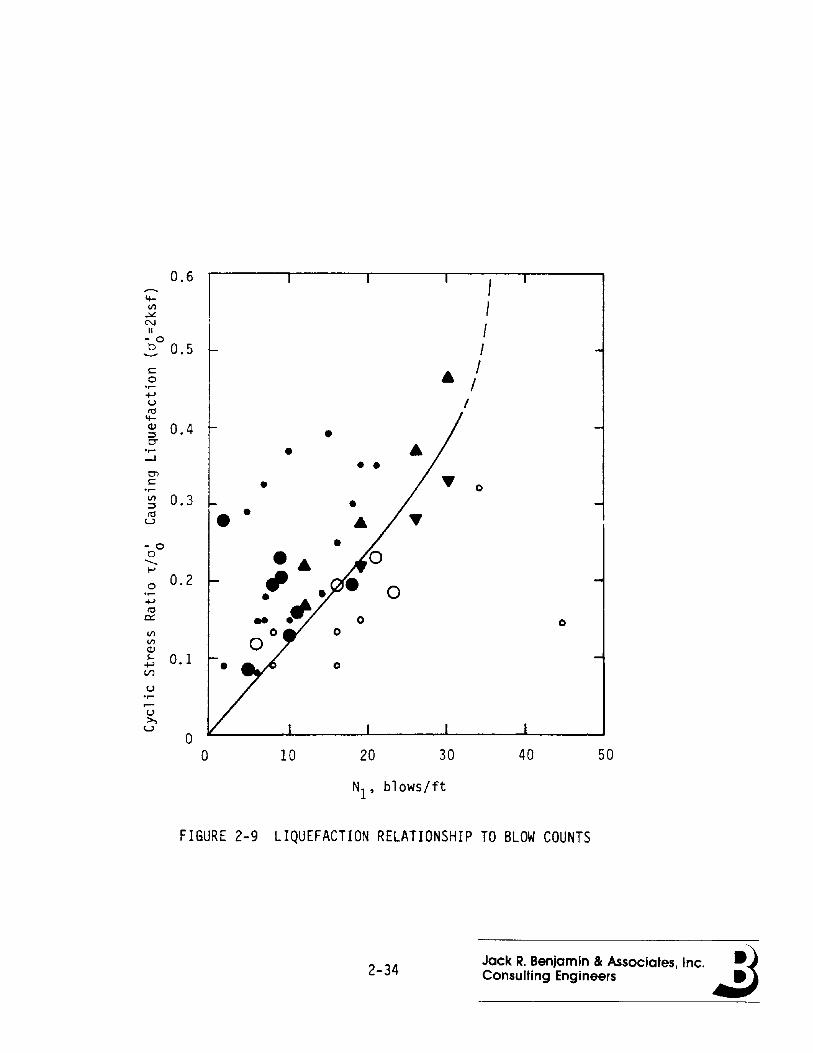
The delineation between the soil resistance that Is adequate, and
that which Is Inadequate, to prevent liquefaction for a given ground
motion Is shown In Figure 2-9. This delineation was empirically
developed from field observations. The line of dem~rcatlon between
liquefaction and non-liquefaction Is obviously not fixed and could be
considered a random variable, with the line shown In Figure 2-9 simply
representing a mean value relationship between the strength parameter,
Nl, and the cyclic stress ration causing liquefaction.
The linear portion of the mean value relationship Is written:
Assuming a coefficient of variation of 0.20, the standard deviation of
Nl Is:
With this Information, field data on the distribution of SPT blow counts,In a given layer, and the distribution of qo' the probabilities of
various percentages of a layer Ilqulfylng may be estimated for a given
maximum ground acceleration. For example, the probability of at least
50 percent of a layer Ilqulfylng given an earthquake'ground
acceleration, am' and effective overburden Is written:
2-22 Jack R. Benjamin & Associates, Inc. ~)Consulting Engineers .:J
109-030-H-01
co
P[N1R(SO) - N1L20lamax' o~] = f f(N 1L /amax ' o~)dN1LN1R(SO) ,
where N1R(50) = fifty percentile corrected blow count as measured In
the field,
N1L = the corrected blow count corresponding to
liquefaction for a given ground acceleration.
One such field study determined that the distribution of SPT blow counts
In a sand layer was such that N1R(25) = 7.56, N1R(50) = 10.8, N1R(75) =I
16.2, and N1R(100) = 41.0. The mean value of N1L for Uo equal to 1,640
pounds per square foot was estImated to be 11.9, with a standard devi
ation of 2.38. Assuming a normal distribution and an earthquake wIth am
= 0.2g, there Is a 99.97 percent chance that at least 25 percent of the
layer Ilqulfles. There Is a 99.7 chance that at least 50 percent of the
layer Ilqulfles. There Is a 94.6 percent chance that at least 75 percent
of the layer Ilqulfles, but there Is only a 0.02 percent chance that 100
percent of the layer will liquify.
If earthquakes are a hazard to a particular levee system, then this
type of Information becomes a necessary building block In the overal I
seismic risk assessment.
2-23 Jack R. Benjamin & Associates, Inc. ~)Consulting Engineers 4I:i

109-030-H-01
2.3 References
2-1 Water TechnologIes Board, NatIonal Researh Council, A LeveePolicy for the NatIonal Flood Insurance Program, NationalAcademy Press, WashIngton, D.C., 1982.
2-2 Haan, C. T., "Adequacy of HydrologIc Records for ParameterEstImation," Journal of the HydraulIcs Division, ASCE, HY8,August 1972, pp. 1387-1393.
2-3 Vlcens, G. J., Rodrlguez-Iturbe, J. C. Schoake, "A BayesIanFramework for the Use of Regional InformatIon In Hydrology,"Water Resources Research, Vol. 11, No.3, June 1975, pp.405-414.
2-4 LInsley, R. K., M. A. Kohler, and J. L. H. PaulhUS, Hydrologyfor EngIneers, 2nd ed., McGraw-HI I I Book Company, N.Y., 1975,pp. 338-373.
2-5 Tang, W. H., and B. C. Yen, "Hydrologic and Hydraut Ic DesignUnder Uncertainties," InternatIonal Symposium on UncertaintiesIn HydrologIc and Water Resource Systems.
2-6 Bogardl, I., "Flood Exposure Recommended as a Parameter ForDescribing the Fatlque Loading on Flood Control Structures,"Bulletin of the International Association of ScientificHydrology, Vol. 3, 1968.
2-7 Cedergren, H. R., Seepage, Drainage, and Flow Nets, 2nd ed.,John WI ley and Sons, New York, 1977.
2-8 Browzln, B.S., "Non steady-State Flow In Homogenous Earth Dams AfterRapid Drawdown," ProceedIngs FIfth International Conference on SoilMechanics and Foundation EngineerIng, Paris, July 1961, pp. 551-554.
2-9 Bogardl, I., "Hydrologic, Hydraulic, 5011 Mechanical andMeteorological Aspects of Models Devised For Determining the Degreeof Protection Offered by Flood Levees," Bulletin of the InternationalAssociation of Scientific Hydrology, Vol. XVI, September 1971, pp.45-49.
2-10 Report on Levee Failures and Distress San Jacinto RIver Levee andBautIsta Creek Channel, RIversIde County, Santa Ana River BasIn,CalifornIa, prepared for U.S. Army EngIneer District, Los Angeles,August 1980.
2-11 Turnbull, W. J., and C. I. Mansur, "InvestIgatIon of UnderseepageMIss Iss Ipp I RIver Levees," Journa I of the So II Meehan Ics andFoundations DIvision, ASCE, SM4, August 1959, pp. 41-93.
2-24Jack R. Benjamin & Associates, Inc. ~)ConSUlting Engineers .:J

109-030-H-01
2-12 Marino, M. A., "Water-Table Fluctuation In Semlpervlous Stream-Unconfined Aquifer Systems," Journal of Hydrology, 19,North-Hoi land Publishing Company, Amsterdam, 1973, pp.43-52.
2-13 Department of Water Resources, Findings and RecommendationsBased on the Inspection of Delta Levees During October 1980,State of CalifornIa, December 1980.
2-14 Weir, W. W., "Subsidence of Flat Lands of the Sacramento-SanJoaquin Delta," University of California Report as summarizedby Agricultural Extension Service, San Joaquin County, August,1980.
2-15 Department of Water Resources, Central District, SeismicityHazards In the Sacramento-San Joaquin Delta, State ofCalifornia, October 1980.
2-16 Seed, H. B., and I. M. Idrlss, "Simplified Procedure forEvaluating Soil Liquefaction Potential," Journal of the SoilMechanIcs and Foundations Division, ASCE, Vol. 97, No. SM9,Sept. 1971.
2-17 Seed, H. B., Idrlss, I. M., and I. Arango, "Evaluation ofLIquefactIon Potential Using Field Performance Data," Journalof Geotechnical Engineering, ASCE, Vol. 109, No.3, March1983.
2-25
Jack R. Benjamin & Associates. Inc. ~)Consulting Engineers .:J

FIGURE 2-1 POSSIBLE STABILITY FAILURE MODES
2-26 Jack R. Benjamin & Associates, Inc. ~)Consulting Engineers .:J
13'
~-T-~~~~":"'-"":~~~~~~
L
FIGURE 2a TIME MOVEMENT OF ZONE OF SATURATION
10 75
8 at 60(l)lI'lrtl 6 45
c::lu
+.J (l)
rtl 4 VI
+.J 30 ..s:: (l)(l) E
2 15 ...-"'0 ~rtl~
(.!:) 0
L ~
FIGURE 2b SATURATION LINE SECANT-TIME PLOT
2-27Jack R. Benjamin & Associates, Inc. ~)Consulting Engineers .:J

d
FIGURE 2-3 SIMPLIFIED SATURATION LINE - TIME MODEL
B x
2-28Jack R. Benjamin & Associates, Inc. ~)Consulting Engineers .:J

104 h=l ft.
1~103 0
102+oJ4-......II
101~
V'l>.
100ttl"0..Q)
E
10-1''-I-
Permeability, ft/day
FIGURE 2-4 TIME TO COMPLETE SATURATION
2-29 Jack R. Benjamin & Associates, Inc. ~)Consulting Engineers .:J

a
------------
L
H
h
x
FIGURE 2-5 SATURATION LINE FOR RAPID DRAWDOWN
2-30Jack R. Benjamin Be Associates, Inc. ~1Consulting Engineers .:J
5 ~1 =14 5.0 4.0
..-i
3.0u2.53
2 ~'~1 =5.0
4
3
2N
U 1
0
-1
1
M 0u
-1
0.10 0.14 0.18 0.22 0.26 0.30
H/L
FIGURE 2-6 COEFFICIENTS FOR RAPID DRAWDOWN
2-31Jack R. Benjamin Be Associates, Inc. ~)Consulting Engineers .:J

F1 ood
Levee Section
FIGURE 2-7 LEVEE EROSION PARAMETERS
2-32 Jack R. Benjamin & Associates, Inc. ~)Consulting Engineers .,:J

x
FIGURE 2-8a SEMI-INFINITE UNCONFINED AQUIFER
x
L
FIGURE 2-8b FINITE UNCONFINED AQUIFER
2-33Jack R. Benjamin & Associates, Inc. ~)Consulting Engineers .:J
0.6I
4-
IIII~
N
f11- 0
Ib 0.5I:: • I0 I.~
+-'Iu
ttl4-QJ 0.4:::l0-.~ •-l
c:nI:: • 0.~
III 0.3:::lttl • •u
- 0b-""'0 0.2.~
+-'ttl
cr: 0 0III 0IIIQJS- 0.1+-' 0
l./)
u.~
~
u>,
u0
0 10 20 30 40 50
N1' blows/ft
FIGURE 2-9 LIQUEFACTION RELATIONSHIP TO BLOW COUNTS
2-34 Jack R. Benjamin & Associates, Inc. ~)Consulting Engineers .:J
109-030-H-01
3.0 STABILITY MODEL
3.1 Probabilistic Considerations
During the course of this study probabilistic stability models were
developed for both circular arc and wedge-type landslide fal lures In
Three dimensions. The Initial work on the probability model utilized a
Corps of Engineers levee geometry (see Figure 1-1). Two levee profiles
from Woodward Island In the Sacramento-San Joaquin Delta were also
studied (Figures 3-1a and b). Woodward Island geotechnical Investi
gations produced a large amount of soil and cross-section geometry data.
These data Included 10 cross sections with surface geometries and sol I
profIles, as well as phreatic surface locations. Data from numerous
bore holes were obtained and the soil propertIes of each soil horizon
were estimated from these data. Parameters for the Woodward Island soil
horizons are listed In Table 3-1. The correlation of cohesion and the
tangent of the angle of Internal friction was not estimated.
The analysis of the bore hole data Indicated that the variation In
The parameters for each soil horizon Is random. Data for each soil
horizon were combined to obtain the estimated means and coefficients of
variation listed In Table 3-1. The correlation of soil properties along
the levee was estimated based on the assumption that each pair of data
was jointly normally distributed with a correlation coefficient that
decayed exponentially with the distance between the sample points. The
sample likelihoods for each pair of data points were multlpl led and the
constant term In the exponential decay expression was determined by
maximizing the sample likelihood.
3-1 Jack R. Benjamin & Associates, Inc. ~)Consulting Engineers 4I:i
109-030-H-Ol
Uncertainty In the estimate of this decay parameter Is large, but
not unreasonable, given the type of casual construction and rehabll 1
tatlon of the Woodward Island levees over the past 100 years, or so. A
second case study (Ref. 3-1) Indicates smaller coefficients of variation
to be characteristic of carefully control led engineered construction.
A computer program was developed (see Appendix) which obtains the
probability of landslide failure of given length along a levee. Char
acteristics of the program are discussed In Section 3.2. It Is noted
that this program was designed to provide reasonable estimates of fail
ure probabilities for use In levee systems analysis. It was not
developed to compete with various other computer programs which estimate
safety factors In conventional geotechnical studies.
The probability model significantly extends that used by Vanmarcke
(Ref. 3-1) by virtue of Including, not only a cylindrical, but also an
ellipsoidal shape of the slip surface. In addition, the model has the
ability to consider wedge failures that do not Include passive earth
pressure, and Includes possible hydrostatic and ground acceleration
effects from earthquakes.
3.2 The Basic Three-Dimensional Model
The essential characteristics of the analytical model are shown In
Figure 3-2, using levee Profile C, (Figure 1-1). A circular arc fail
ure surface Is assumed to exist perpendicular to the levee axis. The
arc may Intersect the soil on the riverside of the levee profile below
the water surface so that hydrostatic load may exist. The arc of the
circle can be made very large to approxImate a wedge-type of failure.
Note that this Is not a general wedge failure analysis, since It does
not Include passive earth pressure Influence at the toe. Single sl Ices
3-2Jack R. Benjamin & Associates, Inc. ~)Consulting Engineers .:J
109-030-H-01
can be consIdered or the faIlure surface can be assumed to be eIther
cylIndrIcal or ellIpsoIdal In shape In the dIrectIon of the levee axIs.
The model also Includes the possIble Influence of a horIzontal acceler
atIon to approxImate earthquake effects through the use of a statIc
coeH Icl ent.
For analysIs, the levee Is dIvIded Into segments, as shown In
FIgure 3-2. SlIces through the levee are consIdered as shown. Each
vertIcal prIsm of soIl above the assumed faIlure surface Is treated In
turn In the analysIs. A sol' prIsm can contaIn up to fIve soIl horI
zons. A horIzon can be damp, saturated, or a damp portion can occur
above a saturated portion as defIned by the phreatic surface. The mean
and varIance of soil density (damp and saturated), cohesIon, tangent of
the angle of Internal frictIon, and the Influence of pore pressure are
consIdered In the analysis for each horIzon In accordance wIth Lambe and
WhItman (Ref. 3-2). It Is assumed that durIng failure all segments are
fully mobilIzed along the failure surface so that the block of soIl
InItIally moves as a rigid body.
The simplicity of the model Is advantageous In that It al lows the
consideration of both cIrcular arc fal lures and wedge-type failures In
one model for several condItIons, IncludIng hydrostatic loads, horizon
tal acceleration loads, varIatIons In the phreatIc surface, varIations
In geometry, rapid drawdown, and faIlures In both the rIversIde and
landslde faces.
A mean safety factor and a probabIlity of failure assumIng that the
random varIable "safety factor" Is lognormal Iy dIstrIbuted are computed
for each analysis. InItIal studIes utIlIzed a normally dIstrIbuted
safety factor; but when It was observed that the coeffIcIent of var
IatIon of the safety factor was large for some soIls (see Table 3-1), a
change was made to the lognormal model.
3-3Jack R. Benjamin 8< Assaciates, Inc. .....3Consulting Engineers
109-030-H-01
Results of one such analysIs are shown In Figure 3-3. Note that
the probabilIty of fal lure generally decreases wIth an Increase In the
mean safety factor, but there are exceptIons. As a consequence of the
Increase In variance, the probabilIty of fal lure can Increase while the
mean safety factor Increases, and vIce versa. It Is also Important to
note that an InfInite number of possible failure surfaces exist, each
with Its own probabIlity of failure. The properties of the faIlure
surfaces are hIghly correlated so that the most critical fal lure surface
Is the one wIth the largest probabIlIty faIlure, not the smallest mean
safety factor. Many fal lure surfaces can sensibly have the same prob
abIlIty of failure. ThUS, crItical zones of faIlure exIst rather than a
single critical surface, or arc, as determined In conventional analyses.
That Is, If probabIlItIes of failure are rounded-off to values consIs
tent wIth the uncertaInty In the data, many different fal lure surfaces
have the same lIkelIhood of failure.
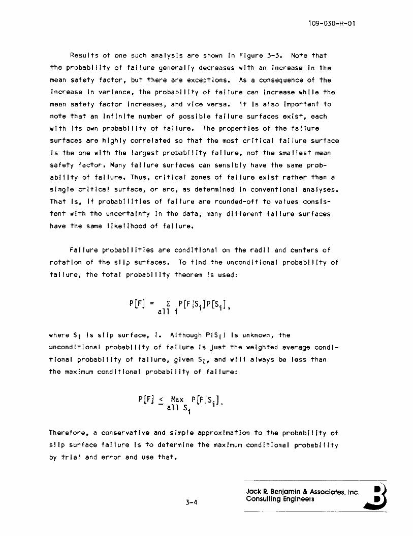
Failure probabIlities are condItIonal on the radii and centers of
rotation of the slip surfaces. To find the uncondItional probabIlity of
fal lure, the total probability theorem Is used:
P[F] = r P[FjSl.]P[Sl'}all; t
where SI Is slip surface, I. Although PISI) Is unknown, the
unconditional probability of failure Is just the weighted average condi
tional probabilIty of failure, given 51, and wi II always be less than
the maxImum conditional probabIlity of fal lure:
P[F] < Max p[FIS.]- all S; l'
Therefore, a conservative and simple approximation to the probabIlIty of
slIp surface failure Is to determine the maximum condItIonal probabIlIty
by trIal and error and use that.
3-4Jack R. Benjamin & Associates. Inc. a.itaConsulting Engineers
109-030-H-Ol
The very large variability In the safety factor was also of
Interest. The coefficient of variation of the safety factor was on the
order of 0.6 to 0.7 for the material properties listed In Table 3-1.
This magnitude of the coefficient of variation precluded the use of the
normal distribution to model the safety factor. Note that the coef
ficient of variation of the safety factor was dominated by the
coefficient of variation of cohesion.
Using the developed model, the analysis of a levee section consists
first of a search of possible centers of slip and radii based on a
single sl Ice. The analysis then considers the extent of failure.
Typical results are shown In Figures 3-4 and 3-5. The most likely
failure length Is one of the basic results of this type of analysis.
Vanmarcke (Ref. 3-1) used level crossing theory In examining the
extent of failure. This study uses the concept of a critical length.
The critical length Is defined as that length beyond which correlations
essentially need not be considered. If a levee Is 5,000 feet In length
and the critical length Is 1,000 feet, then five critical lengths exist
tn the levee and five Bernoul II type trials may be considered In estim
ating the landslide fal lure probability of the 5,000 foot system. The
critical length Is necessarily subjectively defined, but It Is a useful
Intuitive approximation In systems analysis because of Its basic
simplicity.
3-5Jack R. Benjamin & Associates, Inc. ~)ConSUlting Engineers .:J
109-030-H-Ol
3.3 Sensitivity Studies
The analytical model Is complex, and Involves many parameters,
dependIng on the number of soil horizons considered. It Is, therefore,
useful to examine the results of an analysis as a function of the prop
erties of key parameters In an effort to Identify the dominant ones as
well as possibly reduce the amount of field data. The mean of a
property Is easier to estimate with adequate reliability than the vari
ability. However, the coefficient of variation may be typical of the
particular class of sol I, whl Ie the mean varies and can be established
with a few samples.
With the large number of parameters In even a profile with two
layers, the sensitivity study was limited to levee Profl Ie C with a
cylindrical failure surface analysis and two soil horizons. Each sol I
horizon Is characterized effectively by four parameters, the damp and
saturated densities, the cohesion, and the tangent of the angle of
Internal friction. The difference between damp and saturated conditions
for the latter two parameters was not considered. The objective of the
sensitivity study was to Investigate the Influence of different levee
variables, as well as the variability of each of the soil parameters on
the mean safety factor and probability of failure, since It Is the most
difficult value to estimate. Landslde subsidence conditions and varying
phreatic surfaces were considered.
3.3.1 Influence of Soil Parameter Variability
As expected, the shape of the failure probability curves Is not
altered by changes In the coefficients of variation of the soil
parameters. The coefficient of variation of the cohesion had a sig
nificantly larger Influence than those of the other parameters. This Is
consistent with the observed Influence of the cohesion on the safety
factor for the soils considered.
3-6Jack It Benjamin & Associates, Inc. ~)Consulting Engineers .:J

109-030-H-01
The Influence of the coeffIcient of varIatIon of cohesIon on the
probabIlIty of fal lure Is shown In FIgure 3-4. Here, al I other coef
fIcIents of varIatIon are equal to 0.2. SimIlarly, the Influence of the
coeffIcIent of varIatIon of the tangent of the Internal frIction angle
Is shown In Figure 3-5. The dominance of cohesion In the strength
properties of the levee materIals Is shown by the relative magnitudes of
the probability of failure.
In summary, the Influence of a change In the coefficients of
variatIon of all the other soIl parameters (densIty, frIction) was less
than that of cohesIon.
3.3.2 Influence of The Phreatic Surface
StudIes were made of the Influence of the phreatic surface using
levee Profl Ie C (FIgure 1-1). In the first set of analyses, the phre
atic surface was located at fIve different levels, from the crest of the
levee on the riverside to below the levee In the subsoil, as shown In
FIgure 3-6. The soil propertIes for the levee horizons are given In
Table 3-2.
Analyses were made assuming both cylIndrIcal and ellipsoIdal
fal lure surfaces, as dIscussed In SectIon 3.2. The probabIlity of
landslide failure and Its correspondIng mean safety factor were cal
culated as a functIon of phreatic surface location and fal lure length
measured along the levee.
The steady state Influences of phreatic surface location are shown
In Figures 3-7a,b,c, and d. The assumption of a cylIndrical failure
surface are depleted In Figures 3-7a and 3-7b. ProbabIlitIes of fal lure
are seen to be very sensitIve to the locatIon of the phreatIc surface,
whereas the mean safety factor Is relatIvely less varIable. Note that
the probabilIties of fal lure are on a logarIthmIc scale In FIgures 3-7b.
End zone contrIbutIon to the total resistIng moment Is seen to decrease
3-7
Jack R. Benjamin & Associates. Inc. ~)Consulting Engineers Jt:J
109-030-H-01
wIth Increase In rupture lengths. Similar results were obtained as
suming an ellIpsoIdal fal lure surface, Figures 3-7c and 3-7d. Note that
the zone of "most lIkely" faIlure length Is narrower with an ellipsoidal
fal lure surface than with a cylindrIcal fal lure surface and that this
zone broadens greatly for hIgher phreatic surfaces.
The Influence of a rapid rIse In the phreatic surface was also
studied. If, for example, the water level rises rapidly from elevation
7.3 feet to 18.2 feet as shown In Figure 3-8, the phreatic surface as a
function of time can be approximated by several straIght lines.
Analyses were made of the probabilities of fal lure and safety factors
for both cylindrical and ellIpsoIdal faIlure surfaces. The results are
shown In Figures 3-9a,b,c,and d. Note that the time between InItIal and
final phreatic surfaces depends on the permeability and geometry of the
cross section.
3.3.3 Influence of Landslde SubsIdence
To study the Influence of subsidence on fal lure (using a cylin
drical failure surface), analyses were made with two different phreatic
surface conditions and five landslde subsidence conditions. The geo
metry configurations used are shown In Figure 3-10a and the results of
the analyses are shown In Figures 3-10b,c,and d. The probability of
faIlure for maxImum subsidence was almost 50 percent greater than for
the original configuration.
3-8
Jack R. Benjamin Be Associates, Inc. ~)Consulting Engineers ~
109-030-H-01
3.3.4 Riverside and Crest Erosion
Studies of levee slope stability as a function of both riverside
and crest erosion were made using levee Profile C. The water surface
was assumed to be at the top of the levee. The crest erosion conditions
considered are shown In Figure 3-11. It was found that the effect of
both riverside and crest erosion on the probability of failure was
minimal. This is Intuitively obvious In the sense that a change of
between 0.5 and foot near the center of a 20 to 30 foot high earth
structure or on one face wi II not significantly affect any of the terms
In the resisting moment or driving moment equations.
3.3.5 Rapid Drawdown
Two different phreatic surfaces (Fig. 3-12a) were assumed prior to
a rapid drawdown In order to examine riverside levee slope stability.
Levee Profile C (Figure 1-1) was used In the analysis along with a
cylindrical fal lure surface. Drawdown was analyzed In accordance with
Reference 3-2. The results of the analyses are shown In Figure 3-12b,
and c. The relatively high probability of failure due to a complete
drawdown condition shows why It Is cause for concern In geotechnical
engineering. The difference In "most likely" rupture lengths Is due to
the greater coefficient of variation In the safety factor for the higher
phreatic surface.
3-9
Jack R. Benjamin Be Associates, Inc. ~)Consulting Engineers .:J
109-030-H-Ol
3.3.6 HorIzontal Earthquake Acceleration
The Influence of a horizontal earthquake acceleration of 0.05g on
levee Profile C was studied using both a cylindrical and an ellipsoidal
failure surface. Four different phreatic surface conditions were con
sidered (Figure 3-6). The analysis was accomplished by a slight mod
IfIcation of the computer program to Include horizontal Inertia forces
from each segment of each soil column In the soil mass. The Inertial
effects of the water on the riverside face of the levee were not con
sidered.
The results of the studies are shown In Figures 3-13a and b for the
two fal lure surface assumptions. The effect of an earthquake acceler
ation Is to Increase the probability of failure for the different
phreatic surfaces by an almost constant amount. The probability of
failure approximately doubles and the mean safety factor Is reduced by a
factor of about two as a consequence of a 0.05g horizontal acceleration.
3.4 Comparison of Present Study with Vanmarcke's Methodology
As a check on the developed analytical methodology, an example
presented by Vanmarcke (Reference 3-1> was studied. The methods differ
In the correlation decay function, but are otherwise simi lar. Vanmarcke
assumed an exponential decay using the square of the distance between
locations, whl Ie this study assumes a linear relationship with distance
In the exponential decay. The difference between the two decay func
tions Is not large from a practical point of view, since the two
functions employ different coefficients. The analytical model employed
In the present study also Includes a further linearization of the
Influence of correlation of material properties.
3-10
Jack R. Benjamin & Associates, Inc. ~)Consulting Engineers .:J
109-030-H-01
The levee profile used In the comparison Is shown In Figure 3-14a
and the soil properties are given In Table 3-3. The first analysis was
made without a phreatic surface (drained levee condition) using acyl In
drlcal as well as an ellipsoidal failure model. A conventional
slip-circle analysis was also made. The mean safety factor was computed
at 1.17.
Using the data presented In Table 3-3 and a 250 foot long cylIn
dr�ca� failure surface, the mean safety factor was found to be 1.21, and
the probability of failure was calculated to be 0.090. This probability
Is compared to 0.086 calculated by Vanmarcke. Using an ellipsoidal
failure surface and a rupture length of 300 feet, the probability of
failure was 0.049 and the mean factor of safety was 1.30. Figure 3-14b
Is a plot of the probability of failure versus failure length for the
two fal lure surface assumptions. Figure 3-14c contains a similar plot
for mean safety factor.
3.5 Woodward Island Studies
Limited analytical studies were made for two levee cross sections of
Woodward Island. The geometries are shown In Figures 3-1a and b. The
soil properties for both sections were assumed to be the same for the
same soil horizons.
The first part of this study examined the Influence of the soil
property variations on the safety factor and the probability of failure.
As expected, It was found that the most critical failure surfaces, as
defined by the largest probability of failure, depended on both the
mean safety factor and the variability of that factor so that the
critical failure surface was not necessarily associated with the minimum
safety factor.
3-11
Jack R. Benjamin & Associates, Inc. ~)Consulting Engineers .:J
l09-030-H-Ol
Although the minimum safety factor may not define the "most likely"
fal lure surface, It Is Important to note that a fal lure zone exists In
which many surfaces have very simi lar failure probabilities. This being
true, from a practical engineerIng poInt of vIew, It Is not necessary to
determine the mathematically critical surface, since any arc In the
broad fal lure zone will have sufficIently similar properties for
engIneering purposes.
Typical analytical results
In which the mean safety factor
plotted against failure length.
flood level, on the mean safety
probability of failure.
are shown In Figures 3-15a,b,c, and d,
and the probability of fal lure are
It Is seen that the Influence of the
factor Is much sma I ler than It Is on the
The probability of wedge failure along the base of the levee had an
extremely smal I value, beyond the range of validity of the basic data.
3-12Jack R. Benjamin & Associates, Inc. ~)Consulting Engineers .:J
l09-030-H-Ol
3.6 ConclusIons
• The levee length beyond whIch correlatIon Influences can be neg
lected Is herein called the crItIcal length. ThIs length Is based
on the decay of the probabIlIty of faIlure with faIlure length. Each
such crItIcal length In a levee reach can be consIdered to be In
dependent In response to the hazards or loads. The critical length
Is a convenIent approxImation In the analysis of system perfor-
mance.
• A "most likely" faIlure length exIsts In each crItIcal length of
levee, but thIs length Is not sharply defIned. Many lengths have
about the same probabIlity of faIlure. SimIlarly, a wIde varIety of
slIp-surface descrIptions have about the same probabIlity of fal l
ure. A shorter "most likely" fal lure length zone Is associated wIth
an assumed ellIpsoIdal faIlure surface, while a longer length Is
assocIated wIth a cylIndrIcal faIlure surface.
• The probabIlIty of failure Is a better Index of safety than the
safety factor, If the slip surface penetrates through soils with
differing propertIes and large varIabIlItIes. The dIfference In
characterIstIcs between an ellipsoIdal and a cylindrIcal failure
surface depends on the soil properties. Differences are more pro
nounced with highly variable soIl horizons.
• Small varIatIons In levee geometry have a mInor Influence on
stabIlity.
• Small variatIons In the location of the phreatIc surface have a
mInor Influence on levee performance. Large variatIons In phreatIc
surface, as Induced by a long term Increase In water level or a
rapId drawdown, result In major Increases In the probability of
faIlure.
3-13 Jack R. Benjamin Be Associates, Inc. ~Consulting Engineers .:J
109-030-H-O 1
• Sensitivity studies Indicate that the variability of the safety
factor and thus the probability of failure In these studies Is dom
Inated by the large variability of the cohesion. Minor vari
abilities can be neglected. It appears likely that the coefficient
of variation of soil properties can be estimated subjectively from
two factors, the natural variability of the soil and the degree of
control evidenced In levee construction. Casual construction Is
associated with much larger coefficients of variation than carefully
control led engineered construction.
3-14 Jack R. Benjamin Be Associates, Inc. ~)Consulting Engineers ~

109-030-H-Ol
3.7 References
3-1 Vanmarcke, LH., "ReI labl I Ity of Earth Slopes," Journal of
the Geotechnical Engineering Division, ASCE, Vol. 103, No.
GT11, Nov. 1977, pp. 1247-1266.
3-2 Lambe, T.W. and R.V. Whitman, Soil Mechanics, John WI ley and
Sons, Inc., New York, N.Y., 1969.
3-15Jack R. Benjamin & Associates, Inc. ~)Consulting Engineers .:J
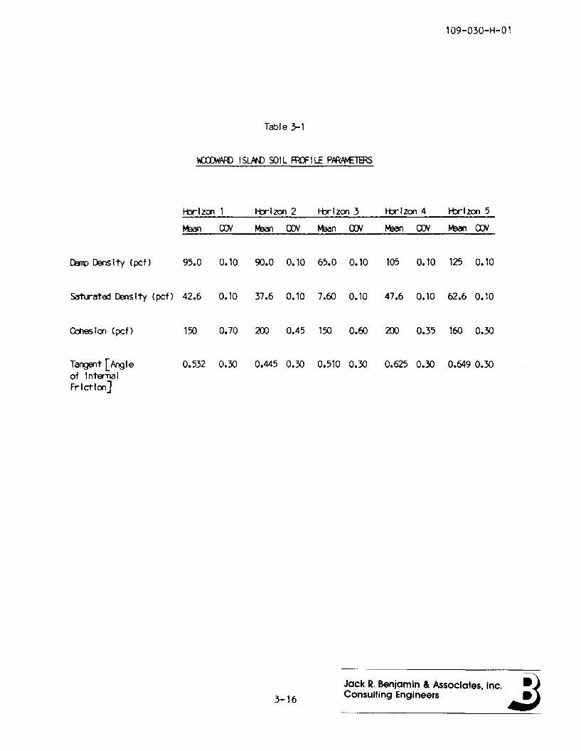
109-030-H-01
Table 3-1
Vf:JJJfVffi ,SlJIN) 9)IL ffi)=" l LE PftfWv£TERS
tbrlzon 1 tbrlzon 2 tbrlzon 3 tbrlzon 4 tbrlzon 5
tJean rDI tJean rDI M3an rDI M3an fJJI M3an fJJI
~ ~Ity (pet) 95.0 0.10 cx>.0 0.10 65.0 0.10 lOS 0.10 125 0.10
Satlrated censlty (pef) 42.6 0.10 37.6 0.10 7.fIJ 0.10 47.6 0.10 62.6 0.10
CctIes Ion (pef) 150 0.70 200 0.45 150 O.fIJ 200 0.35 lfIJ 0.30
Tangent [ Ang Ie 0.532 0.30 0.445 0.30 0.510 0.30 0.625 0.30 0.649 0.30of Inta-nalFrIctIon]
3-16
Jack R. Benjamin & Associates, Inc. ~)Consulting Engineers .:J
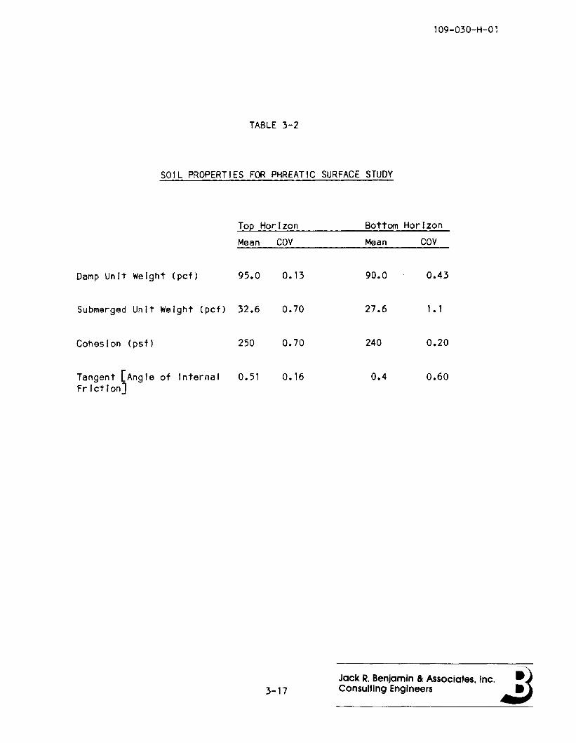
109-030-H-01
TABLE 3-2
SOIL PROPERTIES FOR PHREATIC SURFACE STUDY
Top Horizon Bottom Horizon
Mean COY Mean COY
Damp Unit We Ight (pef) 95.0 0.13 90.0 0.43
Submerged Unit Weight (pef) 32.6 0.70 27.6 1• 1
Cohesion (psf) 250 0.70 240 0.20
Tangent [Angle of Internal 0.51 0.16 0.4 0.60Friction]
3-17Jack R. Benjamin Be Associates, Inc. ~1Consulting Engineers 4I:i
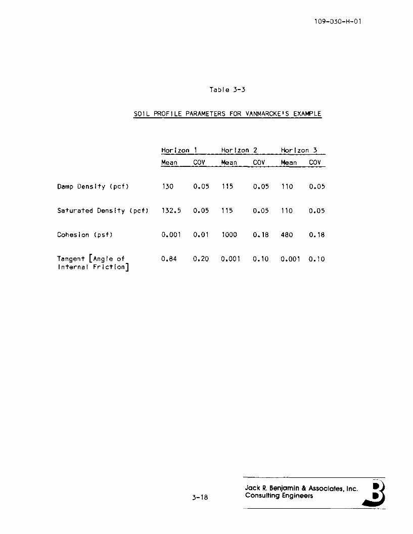
109-030-H-01
Table 3-3
SOIL PROFILE PARAMETERS FOR VANMARCKE'S EXAMPLE
Horizon 1 Horizon 2 Horizon 3
Mean COY Mean COY Mean COY
Damp Density (pet) 130 0.05 115 0.05 110 0.05
Saturated Density (pet) 132.5 0.05 115 0.05 110 0.05
Cohesion (pst) 0.001 0.01 1000 0.18 480 0.18
Tangent [Angle ot 0.84 0.20 0.001 0.10 0.001 0.10Internal Friction]
3-18Jack R. Benjamin Be Associates, Inc. ~)Consulting Engineers .:J
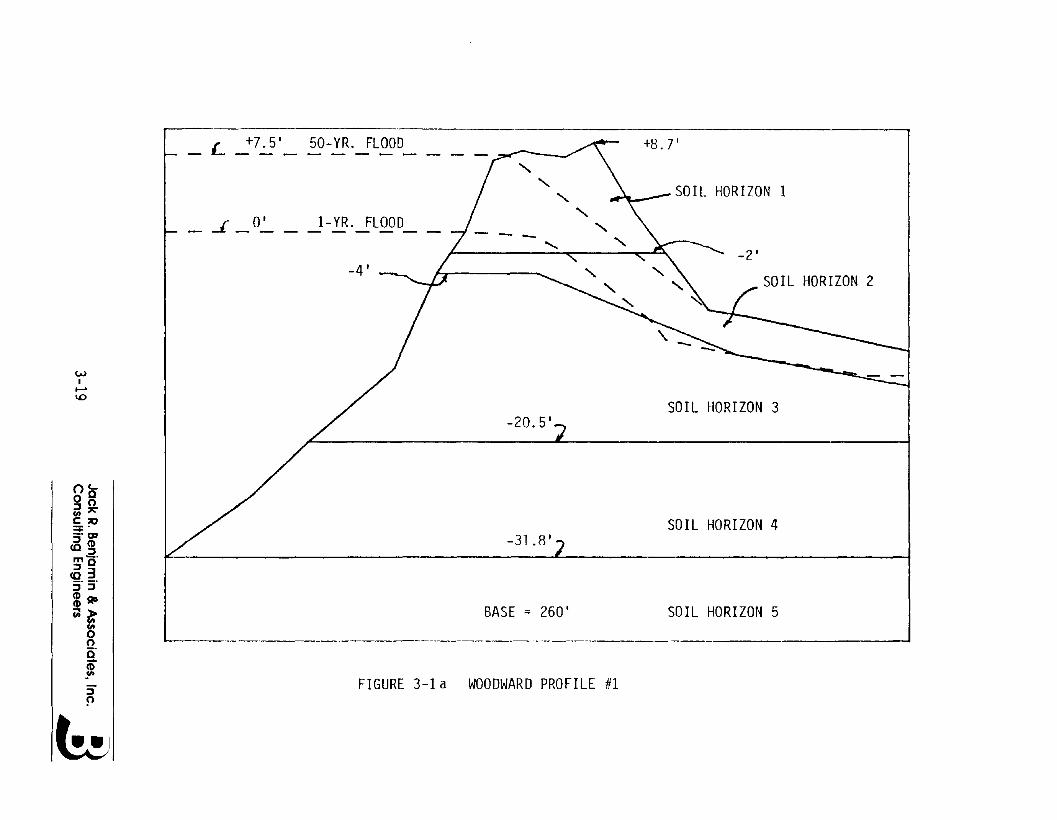
FIGURE 3-1 a WOODWARD PROFILE #1
L +7.5' 50-YR. FLOOD--------
SOIL HORIZON 2
-2'
SOIL HORIZON 1
SOIL HORIZON 4
SOIL HORIZON 3
SOIL HORIZON 5
+8.7'
" " " " "........ "
-20.5'
-31.8'
BASE = 260'
-4'
1- YR. FLOOD_ J 0'- -
WI......
1.0
oc..0°:JOcn'1':"
§:~_. gJ
:J(I)<O:Jg',r<03:;" _.(I):J(I) ADc;;~
t>oc'j:J!'>
b

SOIL HORIZON 3
SOIL HORIZON 4
---
-25
---
SOIL HORIZON 2
""
SOIL HORIZON 1
"" "
""
BASE =
--
-22.5
-26.5'
-8.2'
-0.9' -, l-YR. FLOOD_____ l.- _
SOIL HORIZON 5
WI
No
nc0 0:::JOcn:l'C:,.,~~:::J<D
CO:::JmO":::J 3~"3"<DAD
~~~o
~:::J~
FIGURE 3-lb WOODWARD ISLAND PROFILE #2
6

CENTER OF SLIP CIRCLEXO' YO
SLICE vJIDTHSOIL PRISM
" .....
FIGURE 3-2 SLICE OF LEVEE
/
3-21
Jack R. Benjamin & Associates, Inc. ~)Consulting Engineers .:J
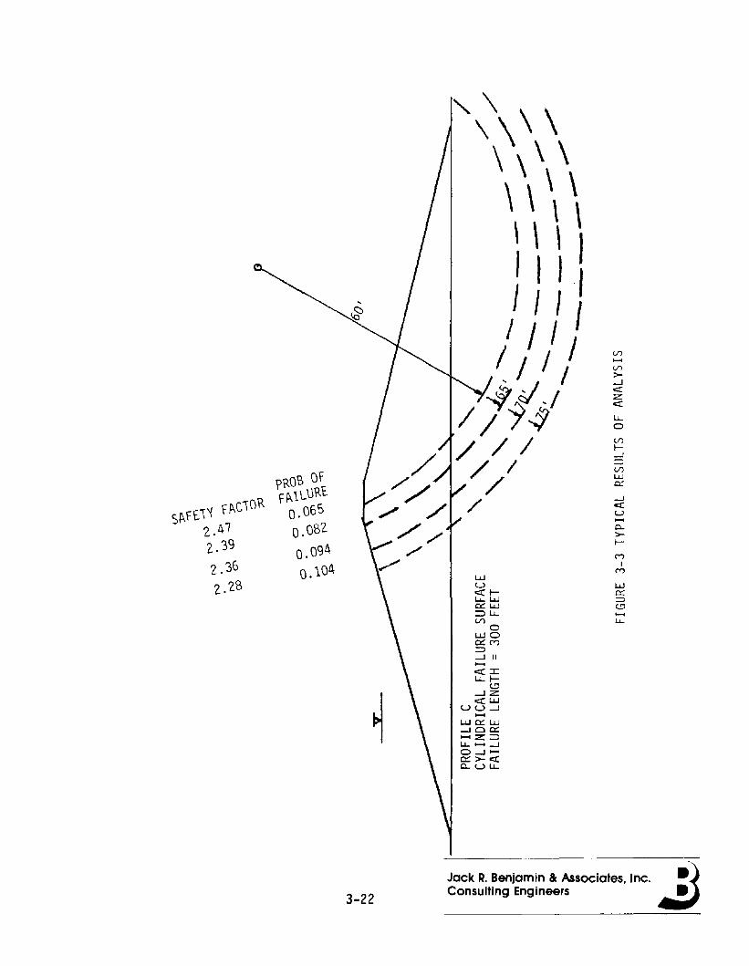
'\\ \ \\\, \ \\ \ \ \\ \ \ \I I I II I I II / I I
/ / / I V).......V)
- oJ I >--I
:"j -/ erzer
II 4 u...0
/ / /V)
~-I
/ /=:J
PROB OFV)
w
/ c:.
S~FEI'{ F~C\ORF~lL\.lRE
/-I
0.06:> eru
0.082.......
2. 47 0->-
2. 39 0.094~
M
2. 36 0. 104I
MUJ
2.28 U werI- c:.l.J... UJ =>a:: L.l.J (.!;l::::J u.. .......V'l u...
0UJOa:: M::::J-I II......C::X:::Cu..1-
t.!l.....JZC::X:W
UU-I......UJ a:: UJ.....Joa::...... z::::Jl.J... ...... .....JO.....J ......a::>-c::x:o..uu..
3-22
Jack R. Benjamin & Associates, Inc. ~)Consulting Engineers .:J

/---- ......
/ \.. BASELINE (ALL CO;s': ...... "-I 0.2) "
I " "-I "I " \I \I \I \I \I \
\IIIIIII
a...
WO::iE::>--l.......<:l.L-
l.LDE~t-
>r--.......--l.......
~E-OOmo0::a...
RUPTURE LENGTH L (ft)FIGURE 3-4 PARAMETRIC STUDY: INFLUENCE OF COEFFICIENT OF VARIATIONOF COHESION ON PROBABIClTY OF FAILURE (CYLINDRICAL FAILURE SURFACE)
3-23Jack R. Benjamin & Associates, Inc. ~)Consulting Engineers .:J
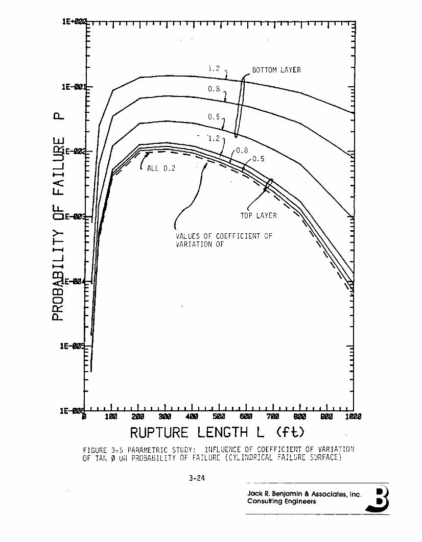
WgfE~
--.J.......<LL
LLOE-I1JI1!~
>-f-.......--.J.......~E-eamo~C-
lE:-IIIIIl~
RUPTURE LENGTH L (ft)FIGURE 3-:-5 PARAMETRIC STUDY: HJFLUENCE OF COEFFICIENT OF VARIATIOnOF TAfl 0 Ui~ PROBABILITY OF FAILURE (CYLINDRICAL FAILURE SURFACE)
3-24
Jack R. Benjamin & Associates, Inc. ~)Consulting Engineers .:J
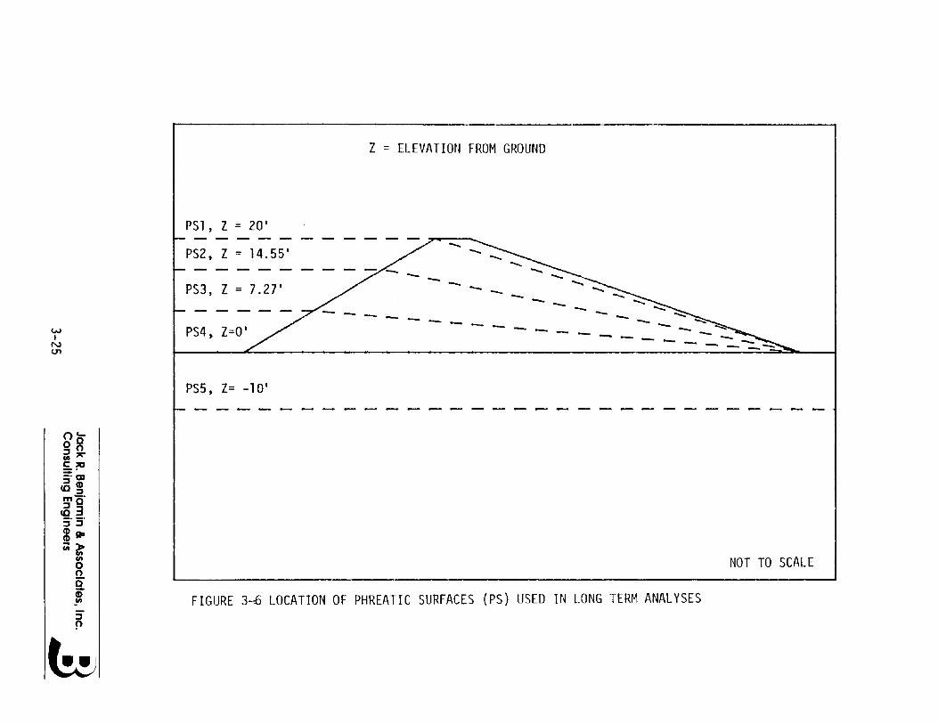
Z = ELEVATION FROM GROUND
PS1, Z = 20'
- -- - -- ~-- ------------ -
- --------
PS2, Z = 14.55'
PS4, Z=O'
PS3, Z = 7.27'
w,N(J'l
PS5, Z= -10'
oc...0°::::JOen'"C;o:::;: "
-" OJ::::J(1)CO::::Jmo"<533"3"mAD~~
enoo0"CDen FIGURE 3-6 LOCATION OF PHREATIC SURFACES (PS) USED IN LONG TERM ANALYSES
NOT TO SCALE
::::J!'l
6
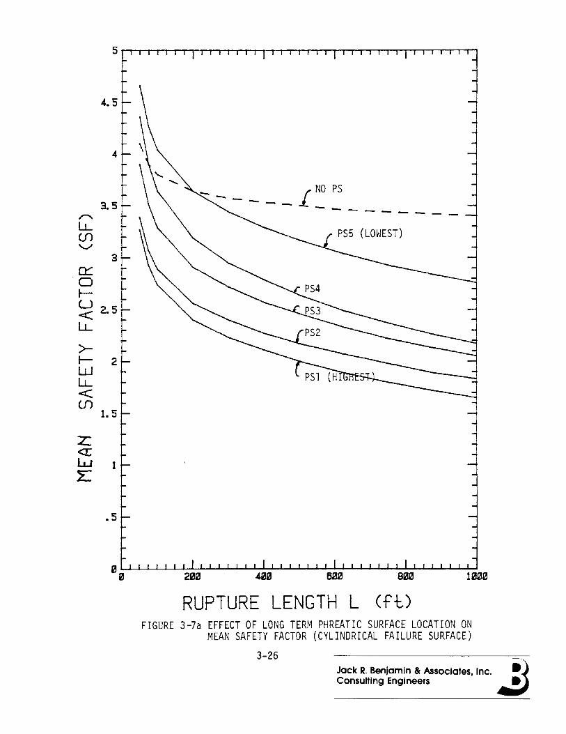
Jack R. Benjamin & Associates, Inc. ~)Consulting Engineers .:J
4.5
,.........LL(f)'-/
n:::0r-u 2.5<::LL
>-r- 2WLL<::(f)
1.5
z:<r:L..J 1E
.5
-- I NO PS
- - -------PS5 (LOWEST)
RUPTURE LENGTH L (ft)FIGURE 3-7a EFFECT OF LONG TERM PHREATIC SURFACE LOCATION ON
MEAN SAFETY FACTOR (CYLINDRICAL FAILURE SURFACE)
3-26

0...
>t-~
-.J~
~E-QIQ1mon::::0...
1 I I I I I 1 1 I I
~OF MOST LIKELY RUPTURE LENGTH
---/ ........ ,.I NOPS
'" " " """"\\
\\
\\
\\
\\
RUPTURE LENGTH L (ft)FIGURE 3-7b EFFECT OF LONG TERM PS LOCATION ON PROBABILITY OF
FAILURE (CYLINDRICAL FAILURE SURFACE)
3-27Jack R. Benjamin & Associates, Inc. ~)Consulting Engineers .:J

2
3.5
c:::o 2.5J-U<:LL
>J-WLL<: 1.5(f)
z« 1UJ~
.5
RUPTURE LENGTH L (ft)
FIGURE 3-7c EFFECT OF LONG TERM PS LOCATION ON THE MEAN SAFETYFACTOR (ELLIPSOIDAL FAILURE SURFACE)
3-28Jack R. Benjamin Be Associates. Inc. ~)Consulting Engineers .:J

3-29
a...
wCk:::::>--.J
=2E
LL
LLo>.-~
--1E~~
~
CD<CDoCk::a...
lE-ea
RUPTURE LENGTH L (ft)FIGURE 3-7d EFFECT OF LONG TERM p) LOCATION ON THE PROBABILITY
OF FAILURE (ELLIPISOIDAL 'FAILURE SURFACE)
Jack R. Benjamin & Associates, Inc. ~)Consulting Engineers .:J
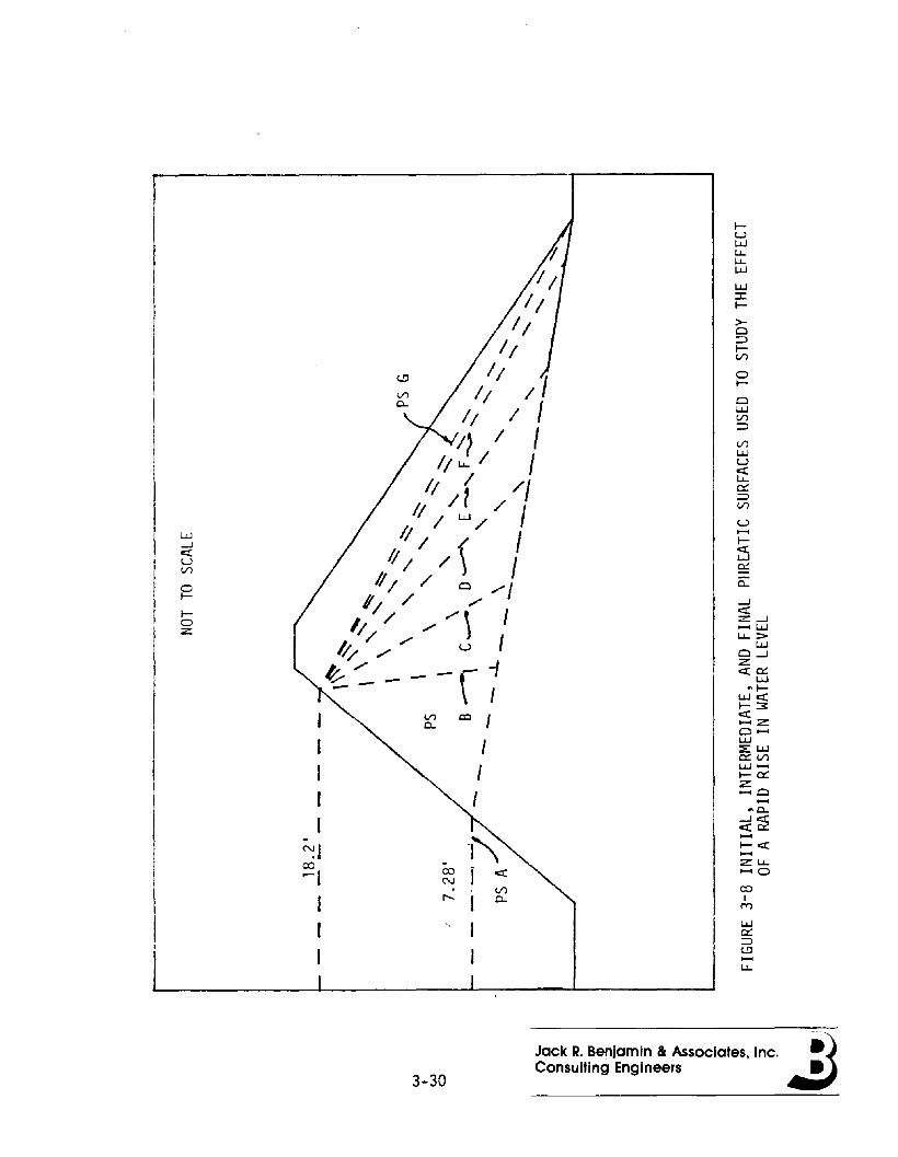
coI
M
W~::l(,!)......LJ..
IUWLJ..LJ..W
W:cI-
>o::llV")
oI-
owV")
::l
V")
Wuet:LJ..~::l(/)
U......Iet:w~:c0..
-Je::tZ -J...... wLJ.. ::::-
wo -JZe::t~
w"I
W e::tI- :3e::t...... z0 ......W:E:W~ V")w ......I-~Z...... 0......
.. 0..
<i~......I-e::t......z LJ........ 0
co I
_ 1'\~ i et:
V"),...... I 0..
I1
V")0..
'III
IIII
IIII
IIII I IIi / 1
II LJ.. I III ( /1
II I~ / I/;/1 (/ I
II I /) I/1/ / 0 /1
1/ / /11/ / / /\ 1/;/// u It-~ --\--1- I
-~Icor-I
III
W-Jet:UV")
ol-
IoZ
3-30
Jack R. Benjamin & Associates, Inc. ~)Consulting Engineers .:J
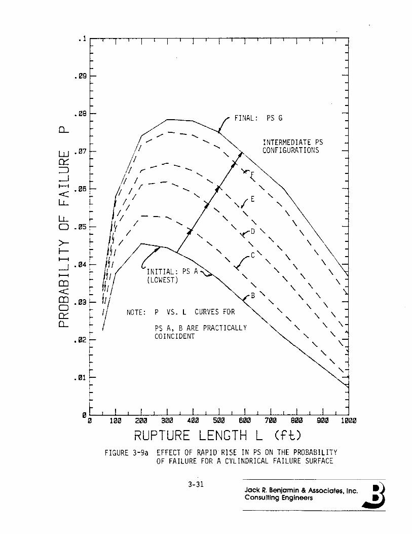
.09
INTERMEDIATE PSCONFIGURATIONS
FINAL: PS G
~z
"" E ""f ",," \,," \
'- <D " \.'- ,," \" C,," \
"/ ,,\ \-< ,,\. \" \. \." \. \ \
B " \. \." \. \.
" " \. \" \. \" "" \.
"" "
PS A, B ARE PRACTICALLYCOINCIDENT
INITIAL: PS A(LOWEST)
// ---I r - "-
I I -,- .......
'I II .......
IIII - - .......
'l //
~ /
~Ifl
11II
~/IIII NOTE: P VS. L CURVES FOR
.01
.02
0....
.08
LLo .05
>-t-+--i-l .04+--i
CD<C§5 .03
0:::0....
RUPTURE LENGTH L Cft)FIGURE 3-9a EFFECT OF RAPID RISE IN PS ON THE PROBABILITY
OF FAILURE FOR A CYLINDRICAL FAILURE SURFACE
3-31Jack R. Benjamin & Associates, Inc. ~Consulting Engineers ~
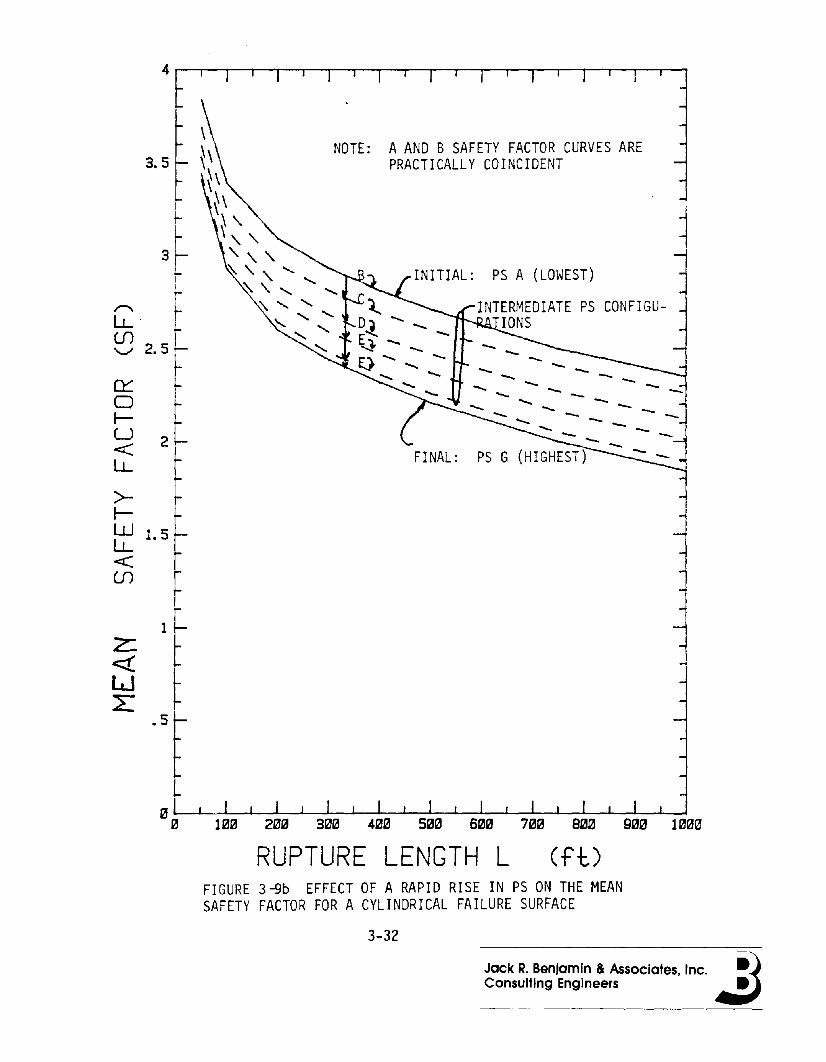
2
3.5
3~Ii
S;. f\"J 2.5.-
Ct:or-u<::LL
>t-~ 1.5
<::en
NOTE: AAND B SAFETY FACTOR CURVES AREPRACTICALLY COINCIDENT
INITIAL: PS A (LOWEST)
INTERMEDIATE PS CONFIGUnONS
RUPTURE LENGTH L ( f-l:JFIGURE 3-9b EFFECT OF A RAPID RISE IN PS ON THE MEANSAFETY FACTOR FOR A CYLINDRICAL FAILURE SURFACE
3-32
Jack R. Benjamin & Associates, Inc. ~Consulting Engineers ~
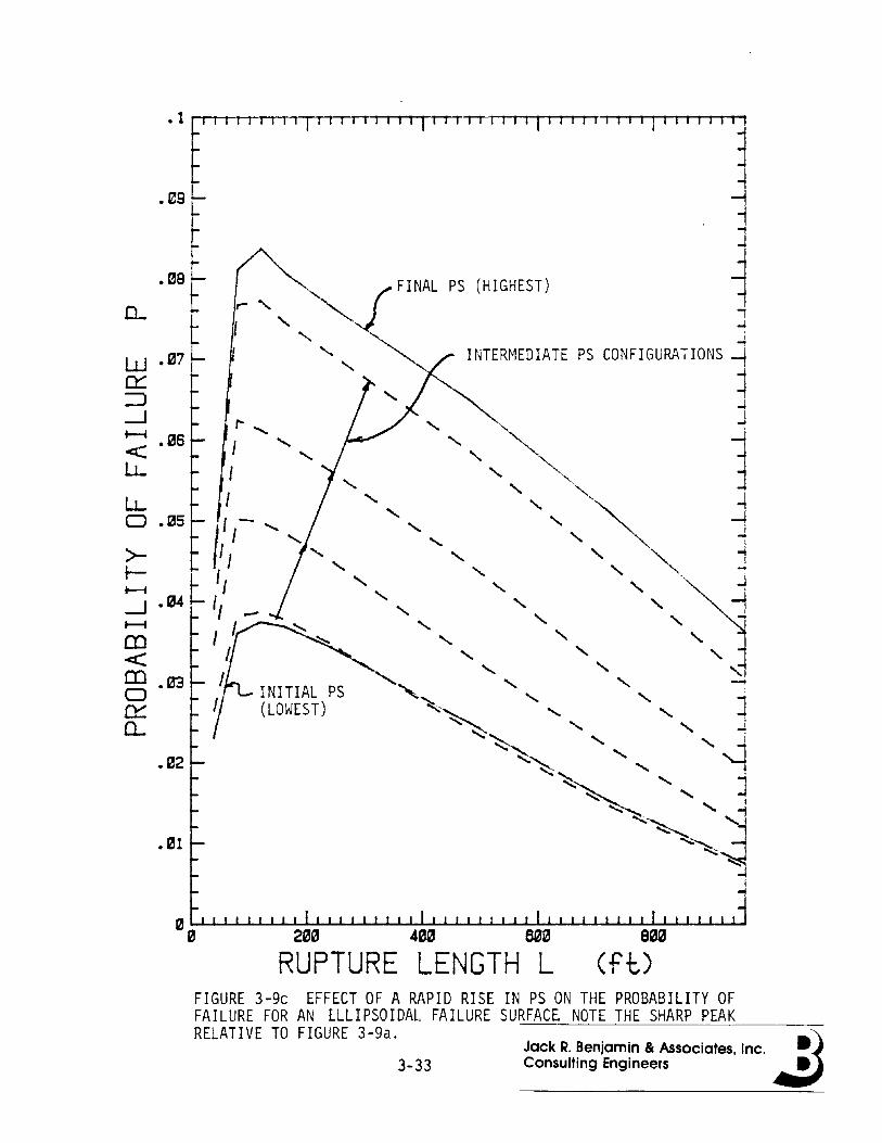
S0e
(ftJ
i
~
INTERMEDIATE PS CONFIGURATIONS -i~..JJ
1~j~:1
FINAL PS (HIGHEST)
2ee 4ee seeRUPTURE LENGTH L
.06
.05
.03
.02
.1 [' , I I , i' , II , " , I I , I I' I , , I
.~~ .
0.. .es t
>r-~
--.J .04~
CD<::CDo0:::0..
W· 07
0:::::J--.J~
<LL
lJ...o
FIGURE 3-9c EFFECT OF A RAPID RISE IN PS ON THE PROBABILITY OFFAILURE FOR AN lLLIPSOIDAL FAILURE SURFACE. NOTE THE SHARP PEAKRELATIVE TO FIGURE 3-9a. jj
Jack R. Benjamin & Associates, Inc. •3-33 Consulting Engineers •

3.5
4 r-r-t-r-I'-1'-1'-1""1T""j""1T""IT""I""1,...,,....""1T'""I......1 ......T'""j"'-1...-........1...-................1...-,--I......., --I......., ......., ......., ...............,--I--I.............1.....1.....1 ....-.~
I
1
~!
~
L!
INTERMEDIATE PS CONGURATIONS
~ 3(J1 INITIAL PS (LOWEST)
: ~:-.....\/----------O - - --/' - - -f-- I \ ---- ----- --~2.5-1 \/' ------ ------ j~ ---- - -~LL r
L' - _ ---- ~-- -~ I ---
~ 2 ~ PS (HIGHEST) - 1z t J~ ~ ~
~ .J
2: loSr ~~ I
]
"""I"""jRUPTURE LENGTH L Cft,)
FIGURE 3-9d EFFECT OF A RAPID RISE IN PS ON THE MEAN SAFETYFACTOR FOR AN ELLIPSOIDAL FAILURE SURFACE
3-34
Jack R, Benjamin Be Associates, Inc,. ~it)Consulting Engineers ~
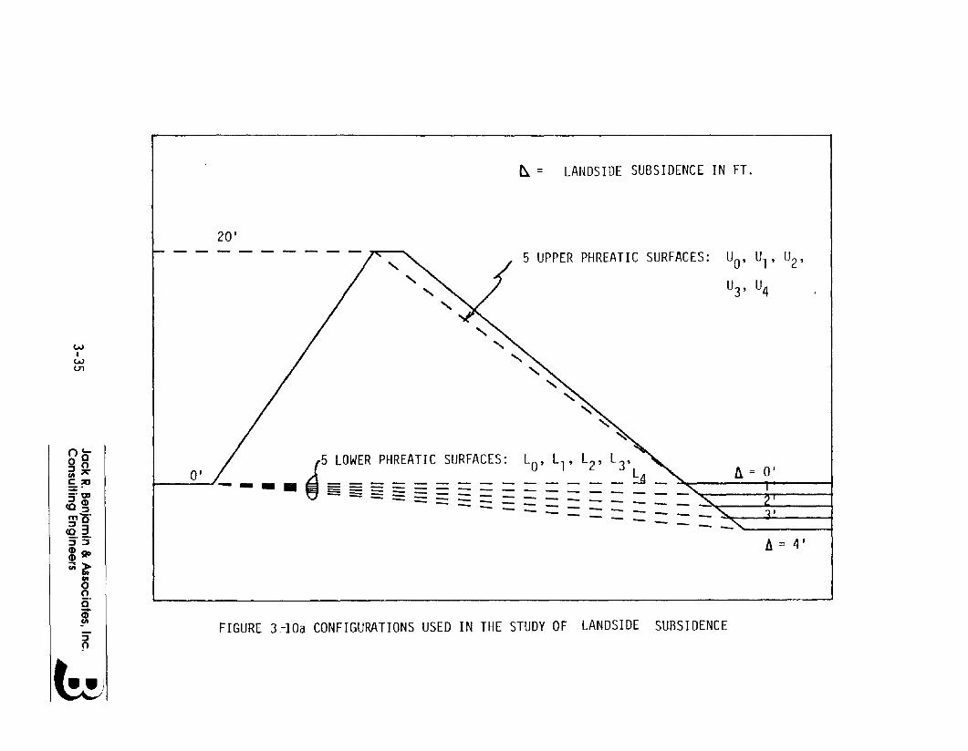
~ = LANDSIDE SUBSIDENCE IN FT.
20'
h = 4'
- --- -- -
L L, ILL, 2' 3 L _ , I~'_ 1_ _ _ ~ _ " ..
- --- --
5 UPPER PHREATIC SURFACES: UO' U1, U2,
U3, U4
.l~O:R~H:A:C~URFACES:
------- --
FIGURE 3-10a CONFIGURATIONS USED IN THE STUDY OF LANDSIDE SUBSIDENCE
O'
WI
W01
::J~
oc....0°::Joen~
£?C~tlD::JeDCO::Jmo"::J 3~"5"eDgo
~l:enoois"m
6

.2~---~-----r----r------~-----'
LOWER PS
UPPER PS
cL .15
W0:::~.-J......-.<:I..L.
I..L.o .1
>-r-......-.--l......-.m<:mo0:::0... .05
ee~---...J.1----.L2----3L.----..J.,,-----15
LANDSIDE SUBSIDENCE (ft)FIGURE 3-10b EFFECT OF LANDSIDE SUBSIDENCE ON THE PROBABILITY
OF FAILURE
3-36 Jack R. Benjamin & Associates, Inc. . ~Consulting Engineers .:J
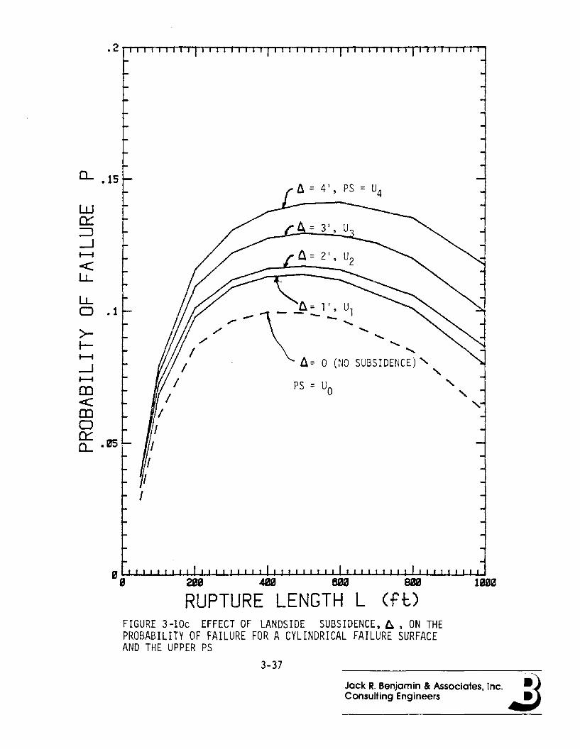
0... .15
w~::)--l~
<:l..L
l..Lo .1
>-r-~
--l~
m<:mo~Q.. .05
28a 48S 80S
RUPTURE LENGTH LBaa
(ftJIBm!
FIGURE 3-10c EFFECT OF LANDSIDE SUBSIDENCE,6., ON THEPROBABILITY OF FAILURE FOR A CYLINDRICAL FAILURE SURFACEAND THE UPPER PS
3-37
Jack R. Benjamin Be Associates, Inc. ~)Consulting Engineers .:J

c...
w~
~...J~ .26
l.L
l.LD
>-.-..........J .64.......CD<CDDc:::c...
.02
RUPTURE LENGTH L (ft)lam
FIGURE 3-lOd EFfECT OF LANDSIDE SUBSIDENCE, A, ON THEPROBABILITY OF FAILURE FOR A CYLINDRICAL FAILURE SURFACEAND THE LOWER PS
3-38
Jack R. Benjamin & Associates, Inc. ~1Consulting Engineers .::J
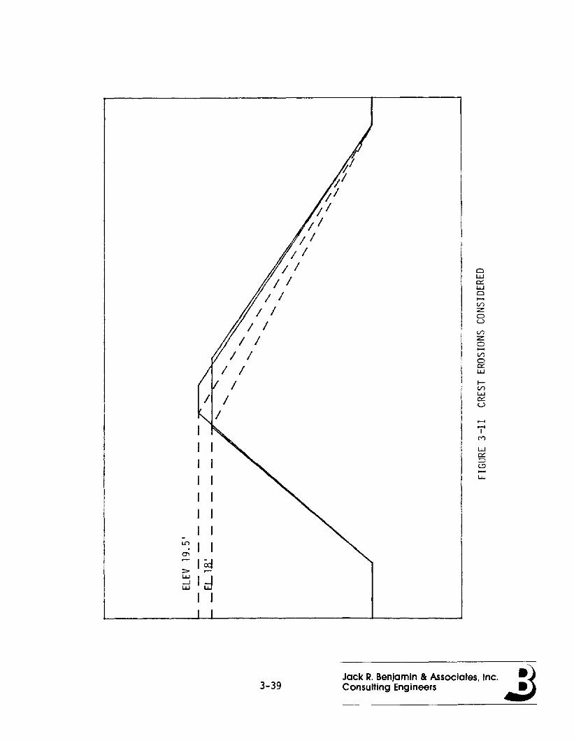
ClW0::WCl.....Vlz:0uVlz:0.....Vl00:::W
~VlW0::U
......I ......
IM
I w0::
I :::>c.!:l.....
I l.J..
IJ
J-LO J I0'1
ICd> .-w
Jd...Jw
I I
3-39Jack R. Benjamin & Associates, Inc. ~1Consulting Engineers .:J
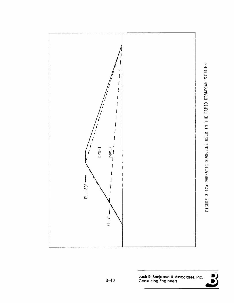
II
II V)
UJ
I ......0::J
I l-V)
I z3:0
I 03:c:r:, 0:::0, 0......0..
f c:r:0:::
I UJ:r:l-
I z......I 0
UJ
I V)
::J
N
'
V)
UJr-UI J" c:r:V)L.L..0.. 0..0:::0 of ::JV)
U......I-c:r:UJ0::::r:0..
- ttl0NN.--<
I.M-J
UJUJ0:::::Jt!'......L.L..
,.....-JUJ
3-40Jack R. Benjamin & Associates. Inc. ~Consulting Engineers .:J
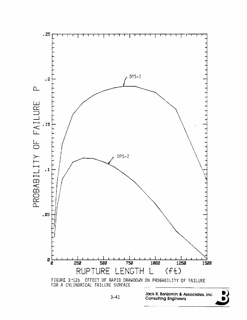
RUPTURE LENGTH L
.2 t- DPS-l
lr0.- jI
W ~
0::::::J-J~ .15 LLL ~LL
~0
>-f-
.1f~
-J~
en l-e<
t "'-en
'"00:::: L0.- ~
.05
~o t-1I.......L-...L-J...-L-.L.....J......L-.JI....-I.-....L.....-L--I--...£.-..l,.~.L.....J..--I-JI....-I.-....L.....-L---L-...£.-..l,.~L.-£-..I
o 250 500 750 1250 1se0
Cft,)FIGURE 3-12b EFFECT OF RAPID DRAWDOWN ON PROBABILITY OF FAILUREFOR A CYLINDRICAL FAILURE SURFACE
Jack R. Benjamin & Associates, Inc. ~)3-41 Consulting Engineers .:J

DPS-2
"1"......
2LL(f)'-.../
0:::0~
U 1.5<:LL
>-~
WLL<: 1(f)
z<rwE .5
15~~
RUPTURE LENGTH L Cft,)FIGURE 342c EFFECT OF RAPID DRAWDOWN ON MEAN SAFETY FACTOR FORA CYLINDRICAL FAILURE SURFACE
Jack R. Benjamin & Associates. Inc. ~)3-42 Consulting Engineers .:J
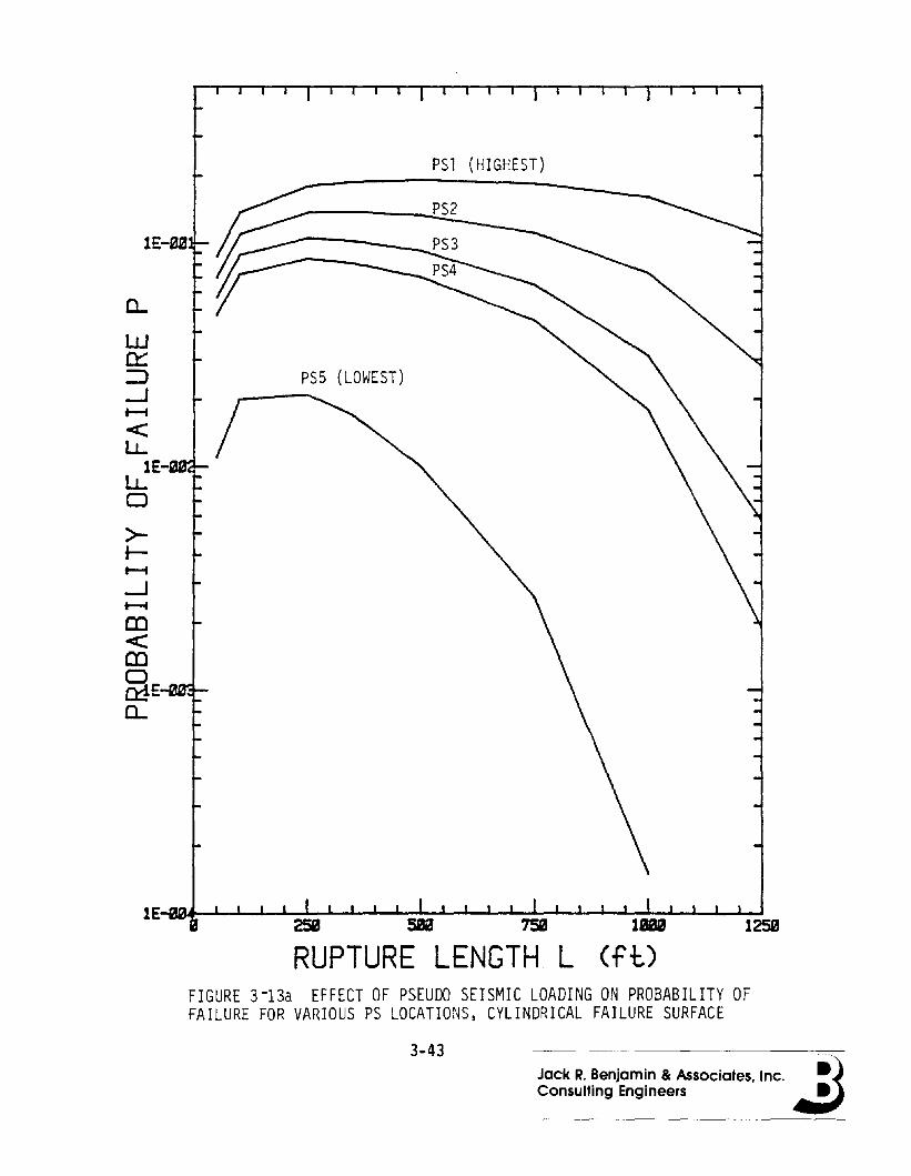
1E-0a
a..w0::::J--lt-i
<:lL.
1ElL.o
>f-t-i
--lt-i
m<:m§E-mE1a..
PSl (HIGHEST)
PS5 (LOWEST)
uma 125m
RUPTURE LENGTH L (ft)
Jack R. Benjamin & Associates, Inc. ~)Consulting Engineers ~
FIGURE 3-13a EFFECT OF PSEUDO SEISMIC LOADING ON PROBABILITY OFFAILURE FOR VARIOUS PS LOCATIONS, CYLINDRICAL FAILURE SURFACE
3-43
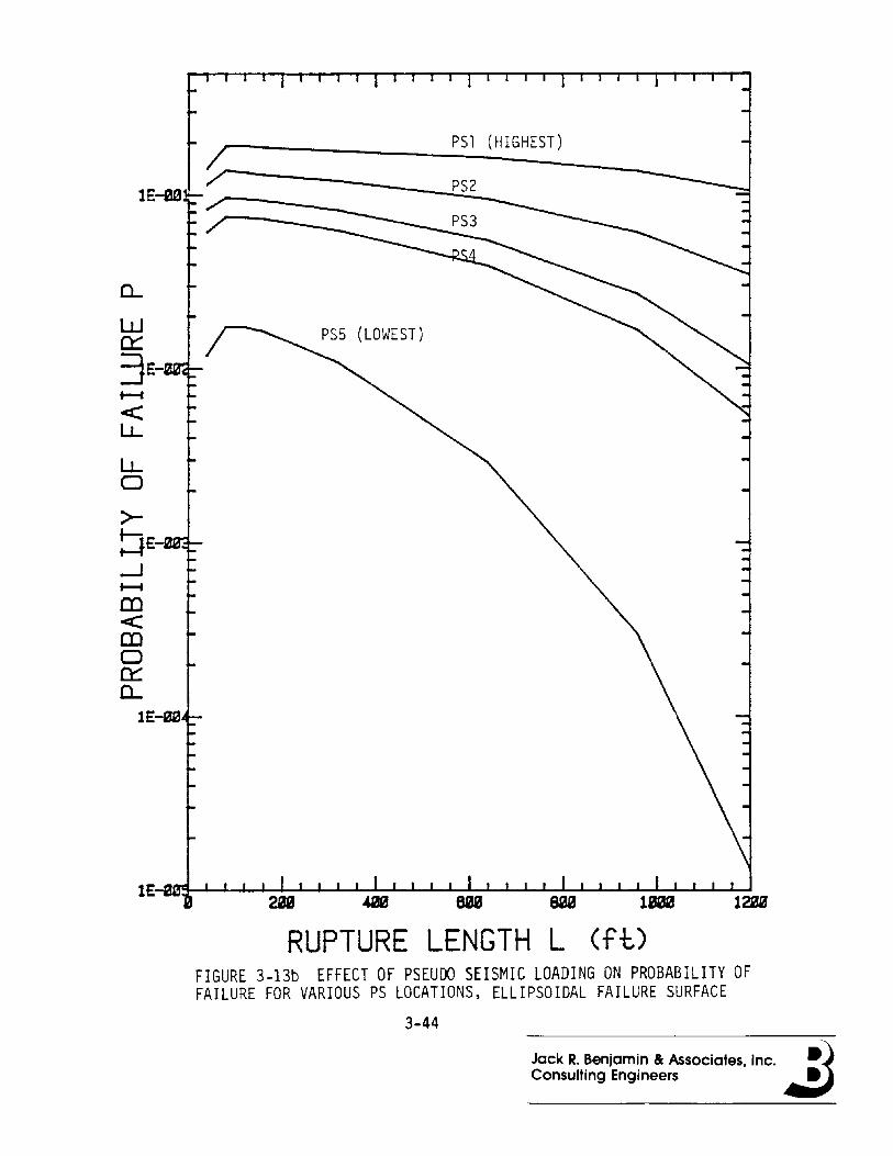
a..w0::
3 E-t--I
<:l.J...
l.J...o>tJE'-wif':~--.Jt--I
OJ<CDo0::a..
1£-00
RUPTURE LENGTH L (ft)FIGURE 3-13b EFFECT OF PSEUDO SEISMIC LOADING ON PROBABILITY OFFAILURE FOR VARIOUS PS LOCATIONS, ELLIPSOIDAL FAILURE SURFACE
3-44
Jack R. Benjamin & Associates, Inc. ~)Consulting Engineers ~

-o~NII
><
3-45
LU--l0-::E~><LU
Vl\.0 r--.~ N LU\.0 \.0 ~
U0::
~z:~>z:.....QLUVl=:l
>-0::f-LU::E0LUc..!'
ttl~......
IM
LU0::=:lc..!'.....lJ...
oII
><
Jack R. Benjamin Be Associates, Inc.Consulting Engineers

a...
W0:::::J-1:2 .06
l..L
l..Lo>-r-......--.J •B4......(D<:(Do0:::a..
.22
RUPTURE LENGTH L (ft,)1259
FIGURE 3~14b INFLUENCE OF FAILURE SURFACE ASSUMPTION ONPROBABILITY OF FAILURE WITH VANMARCKE'S EXAMPLE
3-46
Jack R. Benjamin & Associates, Inc. ~)Consulting Engineers .:J

Z<il.LJ~ .5
ELL! PSO IDAL
1
~otU<1.L
>tWLL<(f)
" ,,~~~.....J--I--'-..J.-..I.-~l-.I-J.-J-...L.7SS-L-...L-..l-.L.....JL...1...LS00--L......L.......L.....J.....J125a
RUPTURE LENGTH L (ft)
Jack R. Benjamin & Associates, Inc. ~)Consulting Engineers .::J3-47
FIGURE 3-14c INFLUENCE OF FAILURE SURFACE ASSUMPTION ON MEANSAFETY FACTOR FOR VANMARCKt·S EXAMPLE
------------

0..
W
~E--1~
-<LL
LLDE·~~
>r-t-i
--1~
~E.-mumoa:::0-
1 YR., ELLIPSOIDAL
1 YR., CYLINDRICAL
RUPTURE LENGTH L (ft)1009
FIGURE 3-15a INFLUENCE OF FLOOD LEVEL ON PROBABILITY OF FAILUREFOR WOODWARD PROFILE #1
3-48 Jack R. Benjamin Be Associates, Inc. ~)Consulting Engineers .:J

II\
"""\
l..L 2 \(f) \'-/
~0t-U<:LL
>-t-WLL<:(f)
1 YR., ELLIPSOIDAL
""-- l ~ ~., CYLINDRICAL
50 YR., ELLIPSOIDAL
RUPTURE LENGTH L1&
(f-l:J1218
FIGURE 3-15b INFLUENCE OF FLOOD LEVEL ON MEAN SAFETY FACTOR FORWOODWARD PROFILE #1
3-49 Jack R. Benjamin & Associates, Inc. ~)Consulting Engineers .:J
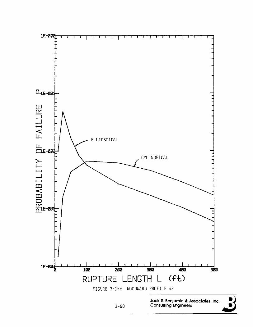
CYLINDRICAL
ELLIPSOIDAL
w~::J-.Jt-i
<:l.J...
l.J...DE-wIr...~
>J-t-i
-Jt-i
m<:mog}E-
RUPTURE LENGTH L (ft)FIGURE 3-15c WOODWARD PROFILE #2
Jack R. Benjamin & Associates, Inc. ~13-50 Consulting Engineers .:J

1
ELLIPSOIDAL
n::o......u<:I.J...
>......WI.J...<:(J)
RUPTURE LENGTH L (ft)FIGURE 3-15d WOODWARD PROFILE #2
3-51 Jack R. Benjamin & Associates, Inc. ~)Consulting Engineers .:J
109-030-H-01
4.0 Systems Analysis and Scenarios
4.1 Systems Analysis Appl led to Levees
levee systems consist of components, such as embankments broken
down Into subreaches), hardware (e.g. closures, pumps, etc.), and opera
tion and maintenance personnel. The system Is surrounded by a physical
and social environment, and suffers from aging.
Henley and Kuromoto (Ref. 4-1) point out that there are two basic
approaches for analyzing causal relations In a systems analysis: for
wards and backwards. Forward analyses start with failure events and try
to Identify al I possible consequences. Failure events are generally
related to:
• human error, such as design error, operator error, maintenanceerror or neglect;
• materials problems, such as low strength;
• the environment, such as earthquakes, subsidence, animalburrowing, flooding, etc.
On the other hand, backward analyses begin with a possible system fal l
ure (e.g., levee breach) and trace backwards searching for possible
causes.
Event and decision trees are forward analyses, whereas backward
analyses are typified by the fault tree. Generally, both of these
approaches are used cooperatively to attain a complete systems rei 1
ability analysis. The backward analysis Is used to Identify the causal
relationships leading to a specific failure, the failure being the top
event of the fault tree (levee breach). The forward analysis assumes
4-1Jack R. Benjamin & Associates. Inc. ~)Consulting Engineers 4I:i

109-030-H-Ol
different sequences of events and specifies a number of scenarios ending
In the system fal lure. The Information which must be developed In order
to write good scenarios are component layout, component failure
characteristics and system specifications.
Component failures are classified as primary failure, secondary
failures, or command faults. A primary failure occurs when a component
Is In a non-working state caused by natural aging (e.g., erosion, subsi
dence, etc.> and In need of repairs to return to the working state. A
primary failure may occur at loads below the design allowable load
condition. A secondary fal lure Is the same as a primary fal lure except
that the failure Is due to excessive demands caused by such events as
earthquake, water stages greater than the design flood level, etc. In
the terminology of fault tree analysis, primary and secondary failures
are known as basic fal lures. Note that these failure classifications
may be dependent. For example, If an earthquake shakes a levee whose
material strength has been weakened over the years by rodents, or eroded
by wave action, then the failure Is a combination of primary and
secondary events.
A command fault Is defined as a component being In the non-working
state due to Improper operation. For example, a closure Is not closed
In time to prevent a less than design flood from Inundating behind a
levee, or a closure Is Inadvertently closed causing water from a
tributary behind a levee to flood the protected area.
An example of how multiple, dependent hazards can be handled for a
levee Is given by Ducksteln and Bogard I (Ref. 4-2>. They present a
methodology for determining the reliability of levee systems which takes
Into account four types of failure hazards: overtopping, subsoil fal l
ure (bolls>, slope stability, and erosion. The loads Include peak flood
level, duration, and volume. The flood height can be assumed constant
but random at all sections, or varying according to backwater effects
and wind waves.
4-2 Jack R. Benjamin Be Associates, Inc. ~)Consulting Engineers .::J
109-030-H-Ol
The resistance of each section Is then determined for each of these
loads and Is expressed In terms of the flood parameter that triggers the
failure. Resistance values are determined by direct measurement (levee
profiles, soil properties) and analysis (seepage, stability). In
general, the flood parameters governing these four types of failure are
different.
The reliability model outlined In Reference 4-2 takes Into
consideration the stochastic character of the flood load, the random
resistance of each section of the levee reach, and the different modes
of fat lure. Fal lure of a levee section occurs If either:
h > H1: overtopping,
h > H2: subsoil fat lure (boll s) ,
h > H3 and w > W: slope stability failure,
h + x > X: wave erosion,
where h = peak flood level,
w = flood exposure (the area of the stagehydrograph),
x = wave height and run-up,
H1 = crest height,
H2 = flood height corresponding to onset of bolls,
H3, W= respectively, the smal lest necessary flood heightand the largest allowable flood exposure forslope stability failure,
X = the highest dynamic water level (peak staticlevel + wave + run-up) necessary for erosionfailure.
The failure event Is for a given levee section written as:
F = (h > H1] u [h > H21 U (h > H3 n w > WI u [ (h + x) > Xl.
For ease of computing the fal lure probability the fal lure event can be
divided Into disjoint events:
4-3Jack R. Benjamin & Associates. Inc. ~)ConSUlting Engineers .:J
l09-030-H-Ol
F = AuBuCuD,
where A = Ih ~ H31 n [h + x > X)I,
B = h > min [Hl, H2 I,
C = [H3 < h < min (Hl, H2) I n [h + x > XI,
D = [H3 < h < min (H 1, H2) I n [h + x < XI n [w > WI.
Subdividing the levee Into subreaches, each with Its own fal lure
event defined, the system failure event Is then defined as:
F = Fl u F2 u • • • Fno
Letting H = min (H1, I, H2, I ) ,
H3 = min (H3,1),
t =,mln (W I ) , for H3, I < h < H,
the conditional probability of failure of the levee system, given H, H3,
and t, Is written:
= 1 -H co
Fh(H) + J J f(h, w)dwdh.H3 t
4.2 Scenarios In Levee Systems Analysis
Scenarios are simply a series of events that we Imagine happening
In the future. We construct scenarios In our every day lives, but
rarely are they as developed or elaborate as those prepared by
researchers working for the government or Industry for military,
political, and economic forecasting.
The term "scenario writing" denotes a technique which attempts to
set up a logical sequence of events In order to show how, starting from
the present (or any other given) situation, a future state might evolve,
4-4Jack R. Benjamin & Associates, Inc. ~)Consulting Engineers 4JJ:i
109-030-H-Ol
step by step. For the purposes of technological forecasting, time does
not always have to be Introduced explicitly, but may only be Intervals
of time, such as one year, ten years, etc.
Scenario writing Is particularly suited to dealing with several
aspects of a problem more or less simultaneously that may be Inter
related. By the use of a relatively extensive scenario, the analyst may
be able to get a "feel" for events and for the branching points de
pendent upon critical choices. These branches can then be explored more
or less systematically.
Scenarios force the analyst to deal with detal Is and dynamics which
he might easily avoid treating If he restricted himself to abstract
considerations. Typically, no particular set of the many possible sets
of details and dynamics seems especially worth treating, so none are
treated, even though a detailed Investigation of even a few arbitrarily
chosen cases can be helpful.
Various methods have been employed to structure scenarios,
Including morphological analysis, event-tree analysis, cross-Impact
analysis, brainstorming, etc., and yet the one which appears to be most
useful to decision makers regarding levee systems Is the event tree.
Not only can environmental events be constructed, technological events
and consequential events can also be evaluated.
4-5Jack R. Benjamin & Associates, Inc. ~)Consulting Engineers .:J
109-030-H-O1
4.3 References
4-1 Henley, E. J. and H. Kuramoto, RelIabIlIty EngIneerIng andRisk Assessment, PrentIce-Hal I, Inc., Englewood ClIffs, N.J.,1981.
4-2 Ducksteln, L. and I. Bogardl, "ApplIcatIon of RelIabIlItyTheory to HydraulIc EngIneerIng DesIgn," Journal of theHydraulIcs DIvIsIon, ASCE, Vol. 107, No. HY7, July, 1981.
4-3 Bowles, D. 5., L. R. Anderson, and R. V. CanfIeld, "A SystemsApproach to RIsk AnalysIs for an Earth Dam."
4-6Jack R. Benjamin & Associates, Inc. ~)Consulting Engineers .:J
109-030-H-01
5.0 CONSEQUENCES AND DECISION MODELING
5.1 Consequences
Flooding Is natural. However, when flooding comes In contact with
developed areas, losses occur. Efforts to mitigate flood losses take
many forms Including flood-plain construction of levees. Flood-plain
management should undertake to minimize the costs associated with flood
plain occupancy by optimizing the Initial cost of development, the cost
of flood protection, the cost of residual flood damage, and the cost of
relief and rehabilItation.
Tangible benefits from flood mitigation Include prevention of flood
damage and land enhancement from more Intensive use of protected land.
The primary benefit from prevention of flood damage Is the difference in
expected damage throughout the life of a land use project with and
without flood mitigation. Primary benefits Include decrease or
elimination of:
• costs of replacing or repairing damaged property;
• costs of evacuation, relief, and rehabilitation of victims, andemergency flood-protection measures;
• losses resultIng from disruption of business;
• loss of crops, and/or cost of replanting crops.
Unfortunately, levee constuctlon activities often encourage over
development in flood hazard zones, thereby Increasing the potential
consequences when and If a levee Is breached or overtopped during storm
run-off.
5-1Jack R. Benjamin & Associates, Inc. ~)ConSUlting Engineers ~

109-030-H-01
Reference 5-1 states that there are approximately 160 ml I lion acres
of land In flood plains, with more than 6 million dwellings and struc
tures. In a recent six-year period there occurred 193 major natural
disasters, of these approximately 80 percent Involved flooding. It has
further been estimated (Ref. 5-2), that levee overtopping or failure Is
Involved In approximately one third of all flood disasters. In 1978 the
total flood damage was estimated at 3.8 bll lion dollars, and the average
annual property loss during the 1970's was 1.7 billion dol lars.
In an example of a single Incident, a recent break In a Sacramento
San Joaquin Delta levee flooded 6,100 acres of prime farm land to a
depth of twelve feet, causing an estimated direct loss of 10 mil lion
dollars (Ref. 5-3). The cost of closing the breach and dewatering the
protected land was estimated at 6.6 ml Ilion dollars, with a crop loss
estimated at 3.25 million dol lars. It was further estimated that
210,000 tons of quarry rock and 340,000 cubic yards of silt wi I I be
required to close the 600 foot long by 85 foot deep breach.
In addition to the direct consequences of property damage and
repair costs, there are many Indirect consequences which should not be
overlooked In the overal I flood mitigation decision process. For
example, a similar break In another Delta levee caused 11,000 acres to
be Inundated by 150,000 acre-feet of water (Ref. 5-4). The Inrushlng
water al lowed salt water to encroach on the Delta from Sulsan Bay. In
an attempt to flush the salt from the Delta, since many communities rely
on the Delta waters for fresh water, 'state and federal water projects
began to release additional fresh water from surrounding reservoirs and
curtal led fresh water pumping for consumption. Within ten days over
300,000 acre-feet of water were released from reservoirs In order to
cleanse the Delta and restore the hydraulic barrier between fresh and
salt water. Even with this large Inflow of extra water, the Delta could
not be entirely flushed and the bulk of the salt had to be removed over
the next several weeks by pumping. In addition, unmeasurable damage was
caused to the San Francisco and Delta fisheries, wildlife, and water
users In southern California. Although the Sacramento-San Joaquin Delta
5-2Jack R. Benjamin & Associates, Inc. ~)ConSUlting Engineers .:J

109-030-H-Ol
Is unique among levee systems, this example Indicates that the conse
quences of levee fal lure may be felt by many diverse interests both near
and far, and that the planning of new levees or rehabilitation of exist
ing levees necessitates the inclusion of al I consequences, not just the
obv lous ones.
5.2 Decision Making
Consequences are variable with magnitudes assigned probabilities
of occurrence. For example, the length and depth of a breach cannot be
known ahead of time. Repair costs are a function of these dimensions
and are, therefore, uncertain. Often, only the expected value of these
consequences Is estimated, with no Indication of the varlabl Iity In the
estimate. For expected value decision making this procedure Is
adequate. However, If there Is any degree of risk aversion In the de
cision making body, It Is essential to estimate the variability, as wei I
as the expected value.
The Impact of the difference between expected-value decision making
and risk-adverse decision making Is Illustrated in the following
example. Suppose there are two different Insurance situations the
Federal Insurance Agency (FIA) can find Itself In. The first Is a
situation In which the FIA Is asked to Issue flood insurance policies
for a community of 10,000 homes which Is protected by a levee designed
to the 100-year flood (disregarding the geotechnical risk of failure at
a lower level, the chance of overtopping Is any year Is 0.01). The
probable number of times this community wi II be flooded In the next five
years, for example, Is governed by the binomial distribution. If a
flood does occur In this community, all 10,000 homes will be flooded
(the chance of this happening at least once In a five-year period Is
0.049). If each Is Insured to 100,000 dollars, this represents a po
tential loss to FIA of 1,000,000,000 dollars. However, from an
actuarial point of view, we find that the expected number of damaged
homes over a five-year period Is only 500, representing an expected
5-3Jack R. Benjamin" Associates, Inc. ._it)Consulting Engineers

109-030-H-01
monetary loss of 50,000,000 dol lars. Thus, the actuarial premium should
be 1,000 dollars per year on the average for each homeowner In this
community.
In the second situation, the FIA Is asked to Insure homes In five
separate communities, geographIcally Independent from one another, each
with 2,000 homes and each protected by a 100-year levee. In a five-year
period, the probable number of times anyone of these communities wit I
be flooded Is again governed by the binomial distribution. As with the
first situation, If a levee Is overtopped, al I 2,000 homes In that
community will be flooded. Therefore, over a five-year period the total
expected number of damaged homes In the five communities Is 500 with an
expected monetary loss (assuming 100,000 dollars per home) of 50,000,000
dollars, just as In the first situation. However, the chance of flood
Ing 10,000 homes or more In the five-year period drops dramatically to
0.000044.
Although there Is a greater chance of some homes flooding In the
second case (0.22 vs. 0.049), there Is a much greater chance of sus
taining catastrophic levels of monetary loss In the first case (0.049
vs. 0.000044). Therefore, a relatively new Insurance program, such as
the National Flood Insurance Polley (NFIP), with an unestabllshed re
serve to cover the type of catastrophic loss represented by the first
situation, should be adverse to the extreme risks Implicit In the use of
the expected monetary value approach.
The graph In Figure 5-1 shows two utility curves representing two
different risk attitudes. The straight line represents an expected
value utility curve and Is the rational one to use If a large enough
reserve were available. The curved line represents a typical risk
adverse utility curve and Is the type that should be used to establish
Insurance premiums for a new Insurance program. If a risk adverse
utility curve were adopted, It would mean that the Insurance premiums In
the first situation should be higher than the second situation, or that
the required levee design level In the first situation should be more
Jack R. Benjamin & Associates, Inc. .:JConsulting Engineers •
5-4

109-030-H-O 1
restrictive than In the second, or both. Requiring that the design
level of the levee In the first case be such that the chance of the
catastrophic loss Is the same as In the second case would mean a design
flood equal to the 100,000 year event. Economically, this may not make
sense, and a more balanced solution would be more appropriate (also note
that the uncertainty In determining the 100,OOO-year event Is tremen
dou s) • In either case, If no f Icod Ing occurs over a per Iod of years and
the reserve Is built up, the utility curve for NFIP approaches the
expected monetary loss value.
5-5
Jack R. Benjamin & Associates, Inc. ~)Consulting Engineers .:J
109-030-H-01
5.3 References
5-1 AlA Research Corporation, DesIgn GuidelInes for Flood DamageReductIon, Federal Emergency Management Agency, Washington,D.C., 1981.
5-2 NatIonal Research CouncIl, A Levee Polley For The NatIonalFlood 'nsurance Program, NatIonal Academy Press, WashIngton,D.C., 1982.
5-3 "CalIfornIa Levee Break Costly," EngIneerIng News Record,McGraw-HIt I, September 2, 1982 (p.18).
5-4 Teerlnk, J.R., "The Delta ExperIence WIth A Drought And LeveeFaIlure", presented to the CalIfornIa Water CommIssIon,Sacramento, September 1, 1972.
5-5 LInsley, R. K., and J. B. Franzlnl, Water ResourcesEngIneerIng, Second EdItIon, McGraw-HI I I Cook Company, 1972,pp. 602-632.
5-6Jack R. Benjamin Be Associates. Inc. ~)Consulting Engineers ~
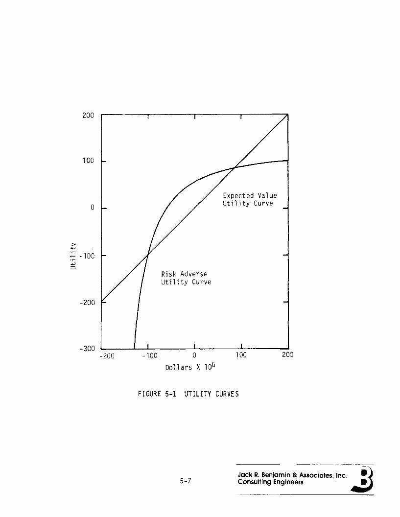
200
100
o
>,+-'
;: - 100.r-
-200
-300-200
Risk AdverseUtility Curve
-100 0
Do 11 ars X 106
Expected ValueUtility Curve
100 200
FIGURE 5-1 UTILITY CURVES
5-7Jack R. Benjamin & Associates, Inc. ~)Consulting Engineers .:J
109-030-H-01
A. APPENDIX
A.1 Levee Stability Computer Programs
These computer programs were developed on the Hewlett-Packard 85
and 86 computers In Basic language. Program SLOPE 86 Inputs the levee
geometry and horizon material properties. Program SEEK86EQX searches
for the critical cIrcle In a given levee configuration. Program
SUPERSTB, calculates the probabilIty of failure and corresponding
safety factor for a levee with rupture length, L, for eIther acyl In
drlcal or ellipsoIdal failure surface. The programs SEEK86EQX and
SUPERSTB have the capabilIty to analyze hydrostatic and/or earthquake
effects, the latter being accounted for by the Inclusion of a horIzontal
load from a constant pseudo-earthquake acceleratIon.
The basIc analytIcal methodology for determinatIon of the mean
factor of safety Is simple and conventIonal, but several Important
assumptIons of a probabIlIstic nature are made that need a brIef explan
atIon. FIrst, In calculatIng the effectIve weIght of a soil prism
composed of several soIl horIzons and an estimated phreatic surface, the
mean effectIve density of each successIve layer from the top down to the
faIlure surface Is used as In conventional analysis. The variance of
weIght Is sImultaneously calculated from the mean densIty, the coef
ficIent of varIation of densIty, and the geometry wIth the additional
assumptIon that the successIve random varIables (weIght) are perfectly
correlated. In the levees of primary Interest, thIs appears to be a
reasonable assumptIon, but there are no data to support the assumptIon
of unIty correlatIon coeffIcIent.
The computatIons for each successIve soIl prIsm yield cohesion
capacIty along the Inclined faIlure surface (mean and variance), fric
tion capacIty (by combInIng the mean and variance of wIth the mean and
A-1Jack R. Benjamin & Associates, Inc. ~)Consulting Engineers .:J

109-030-H-Ol
variance of the tangent of the angle of Internal friction, assuming
Independence between the weight and the friction properties), and load
Ing Influence (mean and variance). The analysis Involves a great many
soil prisms and each has Its own mean and variance for each of the above
factors. For simplicity, It was assumed that the coefficient of vari
ation of total mass was about the same for ai' prisms so that the mean
coefficient of variation of al I of the soil prisms could be used to
characterize the entire soil mass. The problem here Is one of unknown
correlation of properties from prism to prism.
Owing to the large coefficients of variation of the sol'
properties, the safety factor was assumed to be lognormally distributed.
With soils whose properties have a small coefficient of variation, of
the order of 0.2, the safety factor can be assumed to be normally
distributed.
Finally, some field data on the variation of soil properties along
the levee were available. It was assumed that each test boring rep
resented about 100 square feet In horizontal area or a square about 10
feet on a side. The correlation coefficient of sol I properties between
10 foot square areas of soil was assumed to be of the form exp(-CX) In
which C was taken to be 0.015, based on a maximum likelihood estimate
using paired data. X Is the distance between prisms In units of 10
feet.
A-2 Jack R. Benjamin & Associates, Inc. ~)ConSUlting Engineers .:J
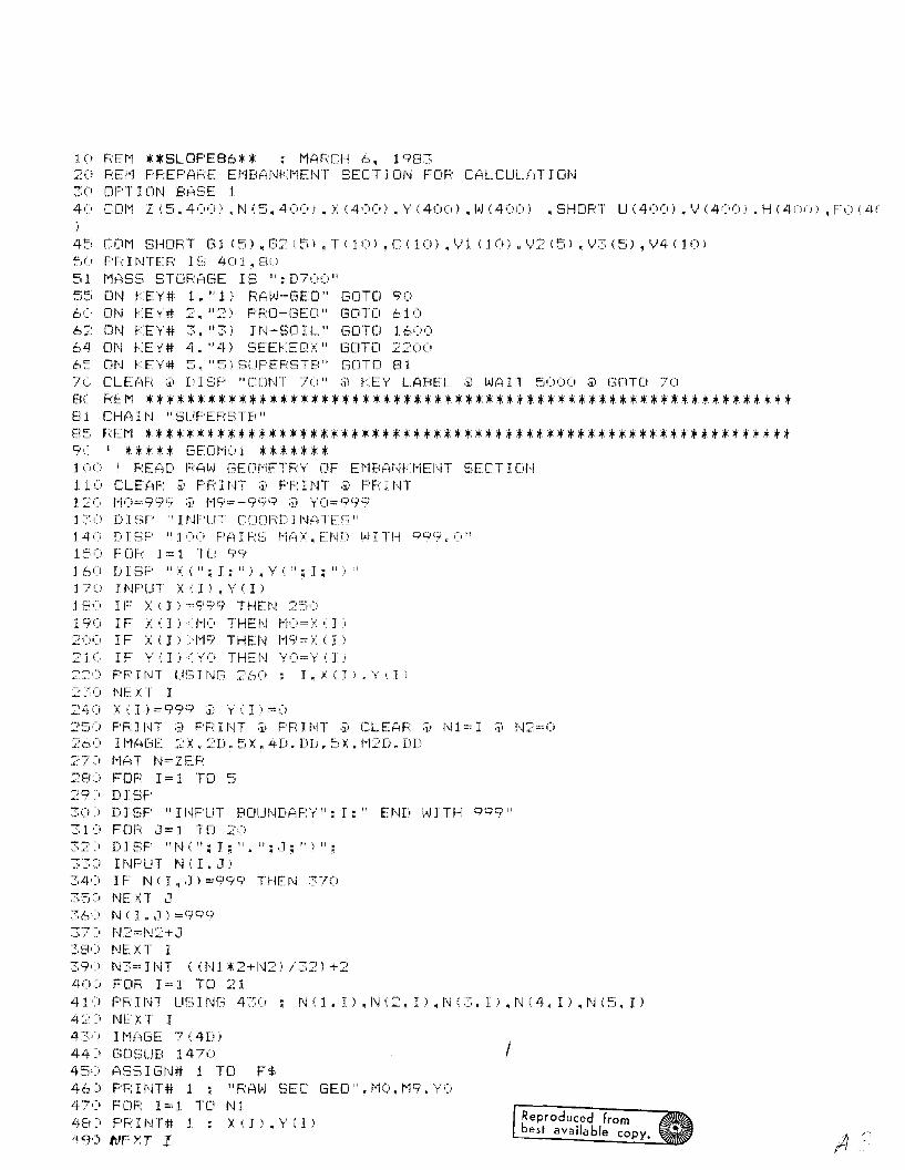
1 (i F:Er-1 * *SLOPE86 * * ; MAF:CH 6, 198320 F:EI"1 F'F:EPAF:E Ef1BANI<1'1ENT SECT I ON FOF CALCUL.{.:) T I Cit'J30 OPT 1ClN BAf:;E 14(' cm-l Z (::;.400) ,N (S, 4(0) ,X (400) • Y (400) ,"J (400) ,SHDPT LJ (400), ''; (400). H (40(1), F':i (Lh
)
45 COM SHOF:T G1 (S',G2(S),T(10l,C(10),V1 (10l.V2(Sl,V3(S',V4(10)5() F'F: I t\jTEF: IS 4(; 1" 8()
51 f1ASS STDF:AC.,E IS ": D700"S=; ON f:EY# 1, I! 1;' RA"J·-GEO" GOTO 9C>6C ON fEY# 2, "2) PF:O-(3EO" GOTD 6106'":: ON f<EY# :::. "3) I N-SO I L" GOTD 160064 m\J fTY# 4," Lf) SEEf:EC';<" GOTO 22006:: ON f'E'r# 5, "5) SLIF'EF:STB" G[lTO 817C CLEAF: ;1; nI E;F' "CONT 70" ;j) I<E'y' LABEL ;1> "JA I T 5000 ;1> (3[\TO 70
BC REM *************************************************************"81 CH~HN "SUFEF:~':;TB"
85 REM ***************************************************************9r I ***** GEOMOI *******100 I READ RAW GEOMETRY OF EMBANKMENT SECTION110 CLEAF: ~ PRINT @ PRINT @ PRINT120 MO=999 @ M9=-999 @ YO=9991 ~~ 'J D I SF' "I NF'UT COOFW I1\J(', TE S l!
14 rj Ii I SF' "100 F'Fj I F:~3 r-1':':);':. END ~'J I TH 9°9. (!"
150 FOR 1=1 TO 991 60 Ii I SF' "X ( " ; I; " ) , Y ': " ; I ; " :; "170 INF'UT :1:(I),Y(I)180 IF X(1)=999 THEN 250190 IF X(Il<MO THEN MO=X(I)20(; I F X ( I ) >r-19 THEI\I f19= X ( II210 IF Y(I)<YO THEN YO=Y(IJ22(:) F'RJf~T USING 26(:) I.X(I)~Y(I)
2:~:'() f\JE XT I
240 XII)=999 @ Y(I)=O2S0 PRINT @ PRINT @ PRINT @ CLEAF: @ Nl=I @ N2=0260 IMAGE 2X.2D.SX.4D.DD.5X.M2DnDD::::7) '''l{.:lT N=ZEF:280 FOR 1=1 TO 5~:9; D I SF'30 J D I SF' "1 NFUT BC1Ut\lD':'jF:Y": I;" END l'JJ TH 999"310 FOR J=1 TO 203:: :i DISF "t\J';"; I ; " • " ; ,]; " ) " ;33:; 1 NF'LrT N ( I • J ;.:::4':; 1F N ( I. ,J; =99':;/ THEt\J 3703':'5) NEXT J36'=' N'; I • ,J ") = 9 9 q
.) i.' N2=1\J2+~1
:::8') NEXT I
Reproduced frombest availa ble copy.
I
39'> N3=INT «Nl *2+1\J2) /32) +240) FOR 1=1 TO 2141') PF:HH U~;It% 430; t'J(I.I).N(2.I),NC3,1),N(L1,I),N(S,I)42::0 NEXT I43':' 1 f-l(jGE 7 (4D)44=' GOSLJB 147045') ASS I Gr\J# 1 TO F$46) PF:INT# 1 ; "RA(.AJ SEC GEO",1'10.M9.Y;:/47') FOR 1=1 1[1 Nl48:' F'F I NT# 1 : X ( I ;. • Y ,; I )119<) NEXT 1.
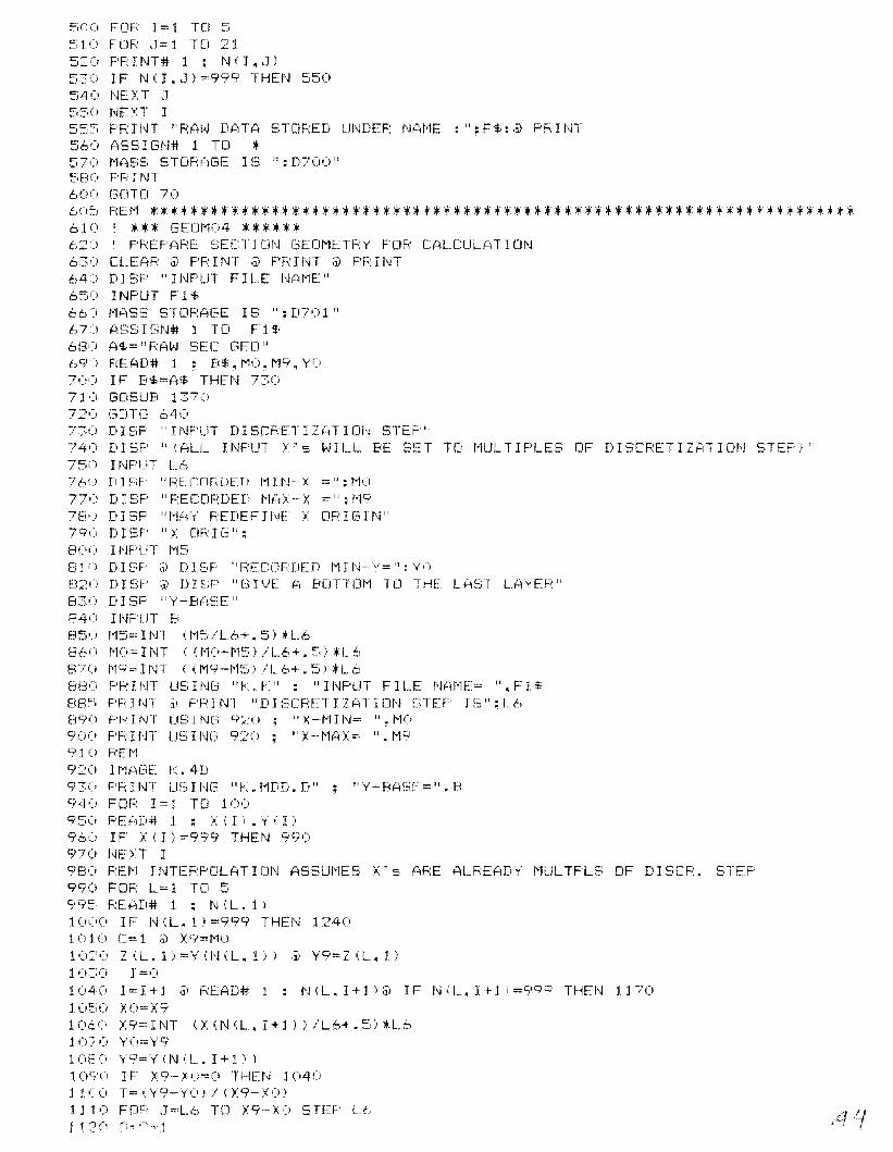
~iCO FOF: 1=1 TO ~;
510 FOR J=1 TO 215:0 PRINT# 1 = N(I.J)530 IF N(I.J)=999 THEN 550540 NEX T ~J
~55() I\JE :s~ T I555 PF:HJT "F:Al-J DATA STOF:ED UI'JDEF: !'JAt-1E :": F$: ,j) F'F:nH560 ASSIGN# 1 TO *570 1'1A!:;S STOF:?1GE I ~3 ": D700":'i80 PF' I NT600 (3CITD 70
605 REM **********************************************************************61 (\ I ** * GE0t'104 ***** *620 I PREPARE SECTION GEOMETRY FOR CALCULATION630 CLEAR @ PRINT @ PRINT @ PRINT64) D 1SF' "I NPUT FILE N{~t-1E"
650 INPUT Fl$66:; 1'1{~SS STORAGE IS": D70 1 "67J ASSIGN# 1 TO Fl$68'~; A$=" F:Al-J SEC GED"69) READ# 1 ; B$.MO.M9.YO70') I F B$=A~~ THEt'J T>~)
71) GOSUB 137('72(i CiDHJ 6407',(i DI~;P "INPUT DISCF:ETIZATIOI'j STEF'"74') DISF' "({~LL INPUT >'5 l-JILL BE SI:~T T[I t-"IULTH'LES [IF DISCF:ETIZP,TIDN STEF')"75'·) I t'WI,.1T L6760 DIf;P "F:ECOri:DED ""IHJ-X =":t-1077U DI SP "F:ECOFmED r-1f':l/ -- X =": 1'197Ei» D I SP "t-1~1\' REDEF I hIE X mn [.31 N"790 D I~;P "X em I (j II :
80(; I NF'UT '-15E; 11) D U3P ij) D 1 SF' !I F:ECLlF:DED 1'11I'j-, y= II :y'(,
82',', D I SF' iJ) D I SF' "G I \jE (-) BOTTm-1 TO THE LAST LAYEF:"Ei3n DISI=' "y'-B?\f;E"84') II'JF'UT B85(i ''''15= un (!"1:'i/L6+. 5) *L.6860 MO=INT «MO-M5)/L6+.5,*L6870 M9=INT «M9-MSI/L6+.Sl*L68E3ii PR I t,n US I NEi "~, n ~,: II : "I NPUT FILE NAI-1E= ". F 1$
8W'i PFnr,n ,i; F'FnNT "DISCF:ETIZATlot'J ~;TEF IS":L.6890 PF: I NT US INC:; 9::(i "X -1"1 I '\j~" ". HO90() PF:HH U~,INCi 920 • "J-·l'lAX:::: ".r-l'?91 (i PEt-1920 H1Af3E ~. 4D930 F'H un 1J:3 Hm "~'. r1DD. D II "y' - BASE= ". B940 FOR 1=1 TO 100950 F:E?1D# 1 • X ( I ) • Y ( I )96() IF' >: ( I ) =999 THE:t" 99()<;)7(' NElT I98(' PEJ-l JNTEF'F'CILATI(JN ASSUI'1ES X' 5 AF:E ALPEADy !"IUL TF'LS OF DISCF-:. STE!='990 FOF: L= 1 TO 599~, F:Ef:.'lD# 1 • N (L. 1 )10':'0 IF N (L. 1) =999 THEN 12401;) 10 C== 1 ;:i) X9=r-l010:::' (, Z (L. 1 ) = Y ( N ( L. 1 » ij) Y9 == Z (L. 1 I10:::;0 J =(i
1040 J=1+1 @ READ# 1 : N(L.I+ll@ JF N(L.l+lJ=999 THEN 117010:;,0 XO=)(910t/' >:9=INT (>:(N(L.I+l»/Lb+.S)*L610/0 YO==Y9lOEO Y9==Y(NiL.I+l»)1090 IF X9-/0=0 THEN 1040l1CO T=(Y9-YOI!(X9-XO)111 (; F[t!=,' J::Lb TD X9-XO STEP L.6
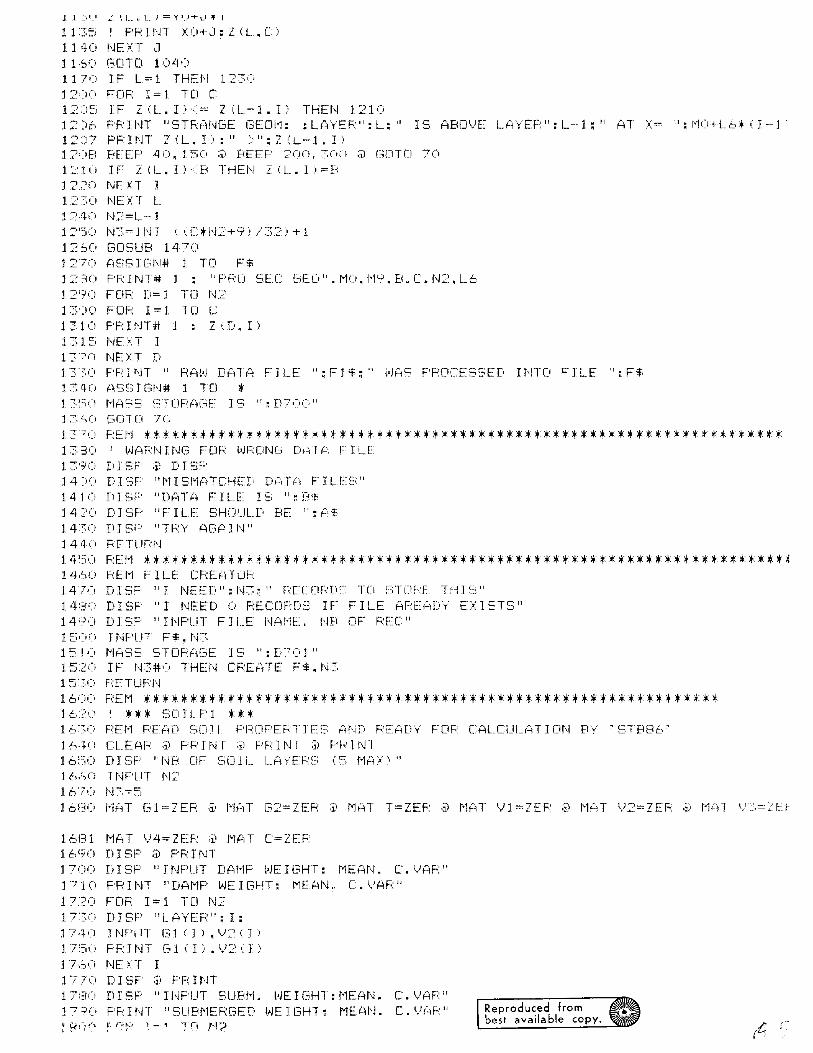
1 t:::;;::; I F'PUH >:0+.1: Z (L, [)
1140 NEXT a1 1,SO GOTO 10401170 IF L=1 THEN 12301 :~I)() F'C)F:: 1=1. TC} C1:2J;::i IF Z <L. I) <= Z (L-l, I) THE I'.! 121012')6 F'RUn "STRANGE (3EOI-1: :LAr'EF:":I_:" IS ABO\)E LfCllEF:I:L-·l:" ':11 X"" ":I-·!O+Lb*<I···j12)7 F'F: nn Z (L. I ) :" :>": Z (L -1 , I )1 :::»El BEEF' 40, 150 ;i, BEEF' 200,30(; ;i) [3[1TO 701210 IF 2(L.I)<B THEN Z<L. I)=Bl2::~(:' f\JEXT I1230 NElT L12·+0 N::::=L·- j
1250 N3=lNl «C*N2+9)/32)+11:? so GOSUB 147()1270 ASSIGN# 1 TO F$1230 F'F.:nn# j : "F'F.:D SEC l~EO".1'10,1'19,B,C.N::'.L6
j 2':;>0 FOF: D= 1 TO I,e13')0 FOF: 1=1 TO C1310 F'F: I NT# 1 : Z (D, 1>131:'; NEXT I13?(; NEXT D13':~,(1 F'F,: nn " PAL') D':iTf~ FILE ": F j $:" l·H';S F'F:OCESSED II\!TO FILE ": F<.t,
1340 ASSIGN# 1 TO *1 :?;~jO I-lASS ~:;TUF:('';(:'f:: I ~3 ": D70(' II
1 ::::;':'0 Gcn 0 7('
137
0 REM *********************************************************************1380 I WARNING FOR WRONG DATA FILE1390 Ii I SF ;)) D I SF'14)() DI'3F' "l'lISI'l':iTCHED DP,TA FILES"1410 DISF' "Ur:.iTA FlU E; ":F~'f
14:::0(' D I SF' "F: 1 LE SHCJUL.D BE I!: P,~,
14::~0 D I SF' "TF:Y A[3(11 I'j"144(' F:ETUF:N
14~50 REM *********************************************************************~14,':,0 PEI-1 FILE CF:E,::nOF:j 4'70 D1 SF' "I NEI::':!) I! : N3:" F:ECDF:Df:', T[I fHDRE TH I S I!
14:3() D I ~3F' "I N~~ED 0 F:ECfJFDf":: IF: FILE AF:EP,[)y EX 1STS II
149U DI SF' "I NF'LJT F 1 i.E l'jAI-1E:" I'm (JF PET II
1 ~~,:;u TNF'UT F$. t,n1;::; I (J MI',SS STDhH3E 1 ~:\ ": D70 1 "15:2(' IF t'f3#O THEN CF:EATE F$, N315::;0 HETUF:N
1600 F;:U-1 *: ***:+ *;; ;; ;; *.. *:+:+;; **:+: **;; .. **.......... *;; .. *;; .. *.. *****.. **' *;; **....**.. :+ *:+ *.. *.. *16.?0 I *** SDIL.F'l .. *+1 6~:;(! F~E:r"1 F~E~~'~[i S(J J I.. F'I::;~[IF'E p'l' I t~E; '::-~ND F~E:{:lD"y' F [iF.~ [~AL [:LIL.(~ T I Clt\~ F(\{ ~ STB86 :-livt(' CLEAI:;: ;j) FF I NT ;i) F'F: I NT ;i) F'h' I NT16;::;0 DEiE' "NP DF SOIL LJiy'Eh:~:; (5 t1~:ln"
16i~'O INPUT N:::'167» N7,=516f30 1-1(,T f31=ZEF: ;ii t-l(d (32=ZEF: ;J) t-1AT T=ZEF: ;]) t-l~H ')l=ZEF: ;il t-lfClT \)2=ZEF: ;]} l-l{1I \,F:S=:ZEF
1681 MAT V4=ZEF: @ MAT C=ZER1690 DISP @ PRINT1700 Ii I SP "I NF'UT DAI-1F l--JE I GHT: t1EAN. C. \.JAF: II
1 7 1(; PF: I NT "D,=it-1F' l--JE I GHT: 1'1EAI'J" C. \/AP"17?O FCiF: 1:= 1 Tel I"C'1TS() DISF' "LA'yEP":I:17,+0 INPUT G1 (1). \)2 (: I ')17'50 F'R: J NT G1 ( 1 ) • v:::' i I )1 '/;'J(i NE cr I1770 DISP @ PRINT1 hJO D I SF' "I NPUT SUPt-1" ('JE I C3HT: 1'1UiN. C. \JAF:"1 7:;;U FF I NT !I SUBI'1EF:C3ED \,lJE 113HT: MEAI'j. C. \)(~F' II
1S".'<" ~: nf' 1-1 '~'(.) ,..1'2Reproduced frombest available copy.
J,C.\.['·,.' L'J..:,r L.t-iTer. ~ J. ~
1820 INPUT G2(1).V3(1118:::;', PF: I t,n (32 ( I ) • \F~; ( I )184'~1 t\~E\T I1850 DISP @ PRINT1860 D I SF' "TAN CJF FR I CT. ANC:~LE: t-IEAN" C. '.JAF,; "1870 PRHH "TP,N FF: f:;lt\J(-): MEJltt\~. C.\/AR"1880 FOR 1=1 TCJ N2*2-1 STEP 21890 DISP "DF:Y LAYER": (1+1) /:?:1900 INPUT T(I).V4(1)1910 PR J t-..lT "DRy':", T ( I ) , \/4 ( I )191:2 n J SF' "vJET LAYER": (I + 1 ) / 2:191·q· 1NF'UT T ( 1+1 I • 1/4 ( 1+:[ )1 9 16 F' F: HJT " v) E T ~ " • T ( I + 1 I , 114 ( 1 + 1 I19'2(; NEXT I1930 DISP @ PRINT194" DISF' "COHESJ(JI\~ (F/L2) : 1'1EAN. C.I/AR"1950 PRINT "COHESlm,~ (F/L'2) : MEAN, C.\IAf;'"19'50 FDF 1=1 TO N:::'>L?-1 STEP 21970 DISP "DF:\' L(.',YEF:": (1+11/2:1 q:3() I NF'UT C ( J ) • \n (I )19 =t,-::- PF H~T "DF'Y:", C ( I ) , VI ( I )1992 D J Sp' " v.J F T L. AYER ": (I + 1\ / :',? :19=?4 INPUT C (1+1). \/1 (1+1)19"Jb FF< It\n "vJET:", [ ( 1+1 ) • I,J 1 ( 1 + 1 ):::"\:;(i t\~E\T J7;':01 ':i D I ~;F' ;i) F'R I I\~T
:?(),2() [:i..Ef2\Fo.:20"0 F:Et-1 ~JT(JF:E F 1L E2() <+0 1"1:3= I NT «t'J3*8+9) /::'.2.' + 120~:!(j (;D~3UB 1460~?()~(, {.,$=" SCi I L F'F::OP"20 70 ASSIGN# 1 TO F$2080 PRINT# 1 : A$2090 r·'F;: J NT# 1 : G 1 ( ) , I.!? ( ) , (32 ' 'j • \/3 ( ) • T ( ) • \)4 ': ) • C ( ) , VI ( )20'/:::; F'F: I I'H " SCi I L F'F:OPEF(T I Ef.:~; SfY.TD Ut\~DEF: THE 1',~At-1E ": F$=~I')o r:~S~;YC:;N# 1 TD *21 '.::' l"lr:~S:::; SJ(JF:r:~GE:: IS": [,7(,,:,"21 J 0 t'3CiTCI '7021 :20' END
21:::0::, FEi·1 ******************,2200 REM **t********t*******::;'210 CHAIN "SFEI<8hEDX"
::::::(, F;~EI-1 *******************
Reproduced frombest available copy.
10 I *t* SEEK86EQX: STREAMLINED SLIP CIRCLE SEARCH WITH END CORRECTIONS ***20 PRINTER IS 401.132 @ PRINT CHR$ (15) @ PRINT @ PRINT @ PRINT @ PRINT30 PF:INT "SEEV86E[1X: STREAl"lLHJED VEF:5IC1N 16-·AUG-83: (.[1. CAPABILIll" ,j, F'F:HJT ;ji
F: I HT40 I SEE L I 5T OF t'lA Ii'J \/AR I ABLES II'J L I 5T nJ[~ OF OLD "5TB86"50 OPTION BASE 160 COM Y(5.4001.W(5.400l.Y6(400l,ZI4001.Z11400) .SHORT X61400l,Y91400J.H I 4(0),F(4()(i)
70 COt'l SH (J RT G1 I 5) ,(32 ( 5) • T U 0) , C U (;) , \11 (J (I) , ~!2 (=.) • \F:, ( 5) ,\'14 (l 0 I80 DIM SI9J.X(9'.TITLE$[80JlOCi Zl$=",'-IO Et·1EifJ·n I I\JF'O " ;j) F9'li":"0" ;j) Z3$="NO F'HF:EAT INFO" ;i) Z2$="ND SDIL INRi:
ij) P$='"(''' ;j) Z4$="NO TITLE ~( D?nE" iii Z5S="NO ACCELEF:?YTION"1 O~) ACCEL=O110 Ot\J fTY# 1," 1 l El"lDft1T" (3DTD 23:2012Ci ON KEY# ~~.":~ l SO I L" GOTO ~;60
130 ON VEY# 3. "3) PHF:E:AT" GOTO :::~460
14(i ON KE'y'# 4. "4) CHE; PHF:" GOlD 277014~i (IN f:EY# :':'i. "=Ii :,,:;ED-CF:" GCJlD 3220150 ON fTY# 6" "6) ACCE1." GOTD ~! 10"15:=; Ot\J VFY# "1. "7) DATE " (30TO 20::160 01\1 fEy# 8, "8 l D I SF " (·3CJTO ISE-JO1'() 1'1?iS~:; STDF:AC";E IE; ": D7UO"180 CLEAF: ;ii f'EY LABEL ;j) D I SF' "COt,jT 180" ;ji D I SF'190 DlElF' Zl~f; ;ii DI~3P Z'::'<.i, ,j) DH-;F' 73'$, ;ii DISF' 24$ ;i) DISF" Z::,$ ;j) WAIT 50()(,200 GOTD 170:~O~:: CL E:AF~
20": D I SF' "ENTEF: TITLE ?"H\JD TODAY' S orflT"20:; INPUT T I TLE'l=~O\~, Z4$="CW TITLE t O{iTE"207 GOTD 180
21 (, F:Et'1 *" *" ***" it *" it *it **" l ***" **" *****************:+ :+ *****22(' F'F: I NT ;i) F'F: I i'n "E,;F'EC I F I CAT IONS FOR: TH I S F:Ui'j"22~ PRINT @ PRINT TITLES @ PRINT23( F'P I NT "~3[11 L. PF<CJF'EF.:T 1 E5: FILE: ": F$24C F'Fo: I NT "Et'iBft-n C:iEDt1ETF:';": FILE ": F9$25C PR I t\JT "F'HF~:t:rCiT I [ SURFACE: ": ;i) IF P$=" (;" THEN F'F: I t\n "NONE" ELSE Fh I I'IT "F I LE
21:..,(" F~ETLIF;~r~J
270 REM *******"************************************28C REM GENERATE A BASIC COORD. USED BY CONVEN. ELLIPS AND CYL..29(l FC}R J=] T"':) N23()(j \{6 ( I ) ==()
::::,1(1 Y9 ( I ) "'0
320 r'JE:): T I33(; H=40'::04 (I F;: E T UFJ'·j
~~u REM ***********************************************~bU *** SOIL-2 '***370 CLEriF: ;il t'1AS~; STOF:f':'-lGE-: IS": 0701 "::;EV' A$=" SO I L. PFWF'"390 DI~;P "SO] 1 Proper-tv Fi Ie I'Jame":400 INPUT F$410 ASSIGN# 1 TO F$420 READ# 1 : B~
430 IF A$=B$ THEN 460440 GOSLin :,' 1:',ii'r 5-0 (;crrc 380
L .. ... -..I \_. l,.....1 1 \1 ',L..L..r-l I l- LJI'.f LL'l::.r r. L.fr ~LJ 1. L r r,L1r--c-_I'; 1 J. t:.::::. 11\1 ~·T't:.!'""'; I 1 LHL L' J. r:t-_L I 1 LJ1\1
47:) F:EAD# 1 : G 1 ( ) • V2 ( ) • (3'::' ( ) • ~)3 ( ) , T .; ;. • V4 ( ) , C ( ) • V 1 ( )48') ASf.; I GN# 1 TO :+49) Z2$="Of:: SOIL INFO"50') GOTO 17051 ,) F:Et'1 :+ * * *:+ *:+:+:+:+:+:+ *:+:+:+:+:+ * *:+:+:+:+:+:+:+:.:+ *:+:+:+:+:+ *:+:+';:,2) I *:+ * ELL I F'SE :+:+:+ *53') F:Et'1 :+ * * * * :+ *:+:+:+:+:+:+:+ *:+:+:+:+ *:+ *:+ *:+ * *:+:+:+:+:+:+ * *:+:+:+54) REM ANALYZE ONE SLICE55') 1<= 1 ;j) 82=8 ;j) 83=8 ;j:; 84=B ,j) (35= 156) L=O @ N9=O @ A2=0 @ A3=0 @ G=O @ F9=0 I ---) MDH.l/14/8357,) G3=62. 4~:;8') I ENTRY=-l5°') FOR I = 1 TT) N260,) Z ( I ) =20610 FOR D=l TO N36~,» Z ( I ) = Z ( I ) + Y (D, I .i +l'J (D. I )630 t'JEXT D640 FO(I)=::O65(i Yb ( I ) =0660 IF 82iW2= (X(i-,~6d»:+(XO-X6(J) THEN 680 I 8/16/8::-,670 Y6(I)=YC'-SCOR (B2:+B2--(}:O-X6(I»:+(XO-)(6 i I») 18/16/83680 NEXT 169U I IF F'$=" 0" THEN 890700 FOR I =:;:-.: TO N~?
7 1 oj F' 4 =:: S[I F: « X0 - X6 ( I - 1 ) ) *" ( X0- Xt, ( I - 1ii + ( YO -- Z ,. I - 1 ) ) :+ (Y 0 - Z ( I - 1 ) » I 8/ 16 / tE7:,?i- P6=SDR (.; ,: 0-- X6 ( I ) ) :+ .; :~: (i- X6 ( I ) ) + .; YO-? ( I :; ) :+ (y'O- 2 .; I ) » I 8/16/83730 IF P4<= 82 OR R6{= B2 THEN 75074U GD1Ci 10::>:' I --) SL I F' [: I F'CLE DOE:::; NOT I NTEF:5ECT i TH SL I CE750 IF P4)B2 DR P6)B2 THEN 80076() I CASE OF NORMAL LATERAL HYDRAULIC LOAD({'.I D1=.:==';:+(Z(])+7(]-1» ;i:; 02=.5*(7(Ii-2(1-1»7 8 0 F 0 ': I ) =:: -- ( • ~':+: G3:+ (H ( I ) :+ H ( I i - H ': I - 1 ) * H ( I -- 1 i ) it: L. 7:+ (y' (I - [I 1+ (j 2 / :;» I 8 / 16 / EI379(; GOTD 102080(l I COMPUTE P5, THE X COORD OF THE POINT WHERE Z(X) INTERSECTS Yb(!)810 1'11"1= (Z (I) -7 (1-1 I) /L6 I SLOF'E m
82(l BB== Z 0: 1 - 1 :; - X6 .; I - 1 :; H·jt·1 lINTE F: CE F' T b83" BBP= (1'11'1;: BP-I'1t'1l 'y0- XU) / (t-11'1 t t'11-1+ 1 I I f3 /1 h./ 8·~;
84,:, CCC= (/0:00+ .; YO-BB) :+. (y'(i-BE) -82:+K:') / 12* (t'lt'1H11'1+ 1 i:; I 8/ :l6/838~.;() F:()[iT 1=-BE{B+'SQF~ (BBB*BBB-2:+:CCC) ~ 8/ 16./8:~;
El60 F:CtCiT:?=·-B:8B-Sm:;: (BBf-i:+8fiB-:2:+.CC:C) I E< 16/83H6~; I PF:INT II I. Z (1-1) • Z (]) ,x.b 0: 1·--1) • ,:6']) ,"'11'1. BE, BBT<, [TC. POOT 1, RCtOT2. F'::,: ":86 L MEAN=(X6(I)+X6(]-1)1/2El6::; IF (F:DOT 1-t·lEfCjt'·j) ;;: (HOOT 1-1·1EAt,j) < (HOC1T2-I'1EAN i :+ (RO[JT2-MEr~N) THEN F'5==F:CJCiT 1 EL ~;E F':=R(IDT::: I 8/16/Er:::;881 I PRINT ]:7(]-1):Z';II~X6(]-1):X6(I):MM:BB:BBB:CCC:RO[lT1:ROOT2:P5:@PRINT89(, H6=Z ( 1-1) + (Z ( 1 I - Z ( 1--1) :; / (X 6 ( I ) - >: 6 ( 1-11 ) :+ (P;::;- X6 ( 1 --1) )90C- 1 F F'4< == B:;:-~ THEN 980enC' I Y6(]-1) E}:CEED~) 7(1-1)92(' Dl =. 5*'; Z (1) +H6' ;j) O:;:-~=. ;:i*'; Z (I) -H6193(' H7=H ( 1-1 ) + (H ( ] I -H ( 1·-1 ) ) / 0: 6 ( I I - X6'; 1--1 ) ) :+ .; P;::;-- X6 ( 1-1 ) I94C FO(I)=-(.5:+G3:+(H(I)*H(I)-H7:+H7):+L7:+';YO-01+02/31) I 8/]6/8395C' X,..,)L=F'5 ,il YI~)L=H6
9c_,( GOTO 10:?097C' I Y6';1) EXCEF.:D~i 7(1)98C 01=.5:+(7(]-11+H6) @ 02=-(.5'(Z'I-11-H61)Q9C' H8=H 0: }-1) + (H'; 1) -H'; 1-1» / (>:6': I:; -X6 (]-1» *(F'5-X6'; 1-1)lOCO FO(])==-';.5*G3l(H8fHB-H(I-1)*H(1-11)*L7'';YO-01+02/3)1 8/16/831010 XAR=::p5 @ YAR=H610:'::0 NEXT]10::::/) FCII:;: I::: 1 TD N2l()Lj(. Hl=H (1) +10 ;]) t'l=J)10;::0 t'Wl'J=H'; 1) H~::~*L_6'L.7 l'UYTE.F CDLl..Jt·lt'j IN F:E~:JEP')E
1055 FED=O I E.O. MOMENT SUMMANDIOtO FDR D=l TO N3'1 .. -., ...; .-", 1.1 1 --I) 1 .. :,: " T", 1 ,_., r~. r r·· r':·1 I f') !_. 1 I r- .:'. r.
1090 I PRINT HiI),H111no DO=SDF: ll>:O--XbiI)*iXO-XbiI)I+('I'O--ZiIli:+iYO-2il»)) I 8/16/f:rj1110 IF 00<82 THEN 113011 :~o
11 :~/)
11401. 1 ~:;CI
I 1 (JO11-'011 !30I 1 (to
12:1012':'()1 2 ~:,()
1 ")-,~
. L·.. I ... )
12+)
Y6ill=0 @ GO TO 1520IF: 1:::: 1 THEN 35ElOIF I=N2 THEN 3580H1= iHI-Y6 i I) I * (HI ''16 (I) Il'JO=OZI(I)=Z(I)-Ybil) ;j) UIX=OFOF: 0= 1 TD N::;Dl=D*2-1 I MAKE DRYZ 1 i I ) = Z 1 ( I ) -WOIF YiD,ll=O THEN 1290IF Y (D. I ) < Z 1 i I) THEt'J 1260t-11::::Gl ([il *71 l I) *L6H.7 ;j) Ul X=Ul X+Z 1 i I I *L6FEQ=FEQ+Ml:+lYO-Y6iI)-ZliI)!2)t-l=t'1+j-l1GOTO 1410Ml=Gl (D)*YiD.Il*L6*L7 @ UIX=UIX+YiO.I):+L6FEQ=FEQ+Ml:+(YO-Y6(1)-ZI(II+YiD.I)/2>
12- l 0 t'1=j-l+t-l1L:::BO Zl il)=Zl (ll-'YiD, I)1 2 q () I F: l.<J i D. I ) = 0 THE N 13801 :3;'0 IF L>J (D. I ), Z 1 i I) THEN 13::=;0130 Ml=iG2iD)+G31:+Z1iI1*L6:+L7 @ UIX=U1X+Zl (ll:+L61315 FEQ=FEQ+Ml:+iYO-Y6(Il-ZI (Il/2)1 3~.:0 t-l=t-1+t-l I1330 01=D*2 I WET] 3i~') C~C1T[l 141 013~)O t-11= ((3:::: iD) +C:i:::') :H'; (D. J I *L6*L7 ;ii Lll X=Ul X+l'; iIi. 11 *L61355 FED=FEQ+Ml*fYO-Y6(1)-ZI (1)+WiD. 1)/2)] 3(:l0 t-'!=!'1+t-l1137 0 Dl=D*2 I WETl::mO 1.-;0=1.-; (D. I)1390 NEXT D14(H) D=D-l14 :, ':i G05UB :::;;6f.lO14:;:0 DEF FNHYF'iXA,Xlj.Y?'i,YBi = SDF: i(XA-XB1:+';XA--XB1+iY(i-'!"Bl*iYA--YE<i) I fl i 16 i f.:1314::;0 DEF Ft,JDETF (XI;., XB, Xc. YA. YB. YC) = .:;; * ; XB* \T-- XC*y'B- U\*'yT+ XC *'!" A+ XA ifYB-d-< * VA'1440 FR I CT]:=: (I'1*F f':.lCTF 1 +t'l\,Jl,HFACTFl'n :+ (YO-y to' I) ) /C~5 *T 'Til )1450 FFICT2=-(Hl*G3*B2*L9*G5*L7*T(Dl)*FACTF21 @ AO=FRICT1+FRICT214c/ i IF (\0< (i THEf\J AO=(i14"70 p,1=Lr"*L.7*C (D1) *B=:*G::j*Fi~CTC[l
14UO (l:?=A:-?+AO1490 A~:'=A-.::;'+(i I:i :;-;')(' [oJ 1 =: (t-1*F--'::iCTDr-l+I'l\)~'HFnCT\/H i ;+: (\0- \6 ( Ii) +FEC'*ACCEL_ *FACTC(\15:0 G=G+Gl+FO(I) @ F9=F9+FO(I)1 =":i ~:2 ' F'F:INT "I, \6 (J). Z (I) ,FEe:. FriCTCA, FEC)*i';CCEU+FACTCA"; I; \6 (I I: 7'] .! : FECI; Fr:iCTC;FED*ACCEL*FACTCA @ PRINT15::0 NEXT I1530 IF ASS (G).OOOI THEN S=(A2+A31/G*SGN (G) ELSE S=-l1540 I PRnn " XC', YO, B, A2, A3. G, S AF;:E ": ;ii PF:lhIT1~;41 I PRII\n XO:YCI :B:rC;A3:Ci:S:;j) PRINT1;:1;';0 RETLJRI\I
15(:l0 REM ****************************************************1=:;70 I **** DISP-4 ****1 :SHO CLEAF:1;:=;90 DI SF'Ib(iO DISF-' USINC; "2(~<.3D.IX)/3(1<.3D,IX)" ; "XO=",XO."YO=",YO," 8=".8,"l..l=",L_l."1=: II I L.()
16: 0 D I SF' US I Nb I,:=:'; f' • t-lD. 4 DE. 1 X)" : " E;= ", S." ~_.J:=". \)." P= Il • F'1620 DISP @ I COPY ---)HP 86 WILL NDT ACCEPT COpy STMNT
1640 FOR K=1 TO 2 Reproduced frombest available copy.
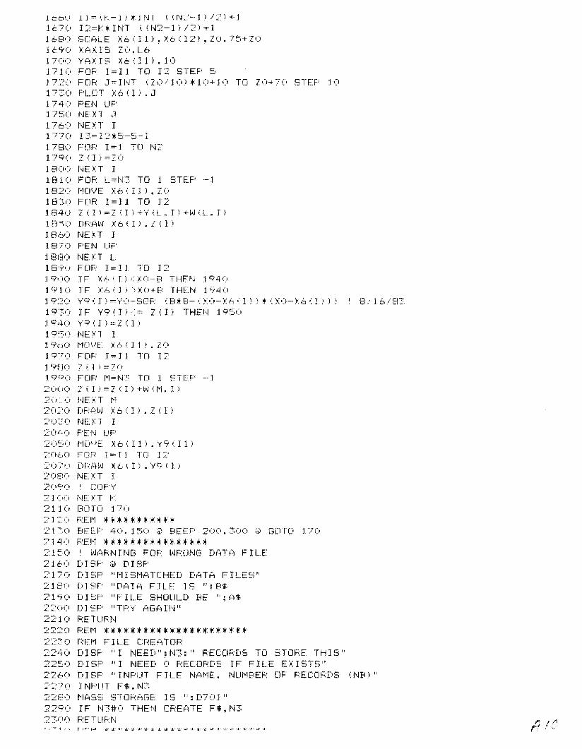
lcb'_' lJ=(.~'-l):t:Jf'j1 ';(f'j:'>-l.l/2.l+J
lt70 I2=K*INT «N2-1)/2)+11680 SCALE X6(ll).X6112).ZO.75+Z01&90 XAXIS ZO.L61700 YAXIS X6(11).101710 FOR 1=11 TO 12 STEP 51720 FOR J=INT (20/10)*10+10 TO ZO+70 STEP 101730 PLOT X6(1).J1740 PEN UP1 7~.;O NEXT ~l
1760 NEXT 11770 13=12*5-5-11780 FOR 1=1 TO N21790 2(1)=7.01800 t'JEXT I1810 FOR L=N3 TO 1 STEP -11820 MOVE X6(11).ZO1830 FOR 1=11 TO 121840 Z(I)=Z(I)+'{(L.I)+l>J(L,I)1830 DRAW X6(II.Zll)18bO NEl.;T 11870 PEN UP18EJO NEXT L18'1'0 FOF: I = I 1 TO I::19(10 IF X6(1)<:,;0-8 THEt\J 19401910 IF X6(I)}XO+B THEN 194019:~0 Y9(])=YO-SDF: (8*8--(\0--X6'1»*';\0--X6';II» I 8/16/E131930 IF Y9(I)<= Z(I) THEN 19501940'1"9 ( I ) =Z ( I )1 q~50 NE)n I19()(i t·1[lI) E: X'":' ( I 1 i . 7019'70 FOR 1=11 TU 1:::'19f1O Z(I)=:?O190 0 FOR M=N3 TO 1 STEP -12(1"0 Z (I) =Z (I) +l>J (t.1. I):>i:O NEXT t'l20:::'0 DF,:A L'J X6 (J) • Z (I)::» ~:,;) NE >: T I20Ll O PEN UF'2050 MOVE X6111'.Y9(ll):Z060 FCJF: 1 = I I TO 1:22(),;'O DF:P\~'J :1;6 ( I) • \19 ( I )20EI0 NEXT J20<C'(i I CDPY'
21(,0 NEXT K2110 GOTD I7()
2120 REM ***********:~ 1'0 BEEF' 40. 150 ;j) BEEF 200. ::::;00 ;i! GUTO 170
2140 REM ****************2150 I WARNING FOR WRONG DATA FILE2160 DISP @ DISP2170 DISF "t'llSl'l?-iTCHED DPITA FILES"2180 DJSF' "DATA FILE IS ":B$21'7 (0 D I SF' "F I LE SHUULD BE ": A$2200 D 15P "TF:Y AGA 1I'J "2210 PETUFN
222() REM **********************22~O REM FILE CREATOR2240 DISP "I NEED":N3:" PEC[)FWS TU STOF:E THI~3"
2250 D E-=)P "I NEED 0 F:ECOF:DS IFF 1LE EX n3TS"2260 D I SP "I NPUT FILE NAt-1E. NUt1BEF: OF F:ECOF:D~; (NB.1":'::70 HJF'UT F$. 1'J32::::80 t-1AS::;; STOHAf3E I ~3 1': D70 1"229() IF N3#(:) THEN CREATE F$nN32~,()O F:ETUFt'Jr-',"-:or "! .. -, '-"1 r- hA .J...J.- '.1,- \.I.- oJ ....... oJ.' -J.. 01.. oJ.. '.1: ..1.. ..l.' '.1." 101.' .I' U.· •.l. . ..1.. oj ••.1..•.1.. _.1' .J....1
r 1/1JiA . ,,- ,I '-"

:::3:» F<Er-l ENTFY FOF: NE(..<J El'lBAr'H·r-1ENT I NFOSI'IAU I [I C)23~:;() CLEAF: ;i; t·1ASS STOF:?~GE I S ": D7(> 1 11
2340 D I SF' "I NPUT FILE NAr-1E vJ I TH Er-1B~. PROCESSED GE()t1ETF~Y"
23~)0 INPUT F9$::360 ASS I GN# 1 TO F9$;~370 A$=" F'RO SEC GEO"23£30 READ# 1 • B$23QO IF B$=A$ THEN 24202400 GDSLJB 214024)0 GOTD 234024:~0 Z 1$=" 01< EMB~:J1T INFO":?4~;0 GOTD 170
2440 REM "'*"""*"'**'*****""'*24:;0 F:H1 I NF'UT PHREAT I C SUF\:J=.-ACE2460 CLEAR ;ii t1ASS STOR'::~GE IS": D70 1 "2470 IF F9$#"O" THEN 250024E~0 DISF' "(3I\/E EMB~r1T INFO FIRST"24°0 GOTD 2:::::40;!::,on ASS I Gt'J# 1 TO F9$25]0 READ# 1 B$:?5::'o) F:EAD# 1 >:8. X9. lO. t\J2. N3. L625~;0 FOR 1=1 Tel 1\1225£0 X6(Il=L6*<I-l)+X825:;0 l'iE n I25\~\(i FOF: t.= 1 T"Ci 1\~3
2570 FOR 1=1 TO N2::~=IEu) F:Ef~D# 1 ; Y (L" I )2:j Cl O NEXT I2600 NEXT L2610 DISF' "NAt'IE FILE tAJITH F'HREATIC SURFf~CE"
26:\) D 1 SF' "I NPUT 0 1 I') I\lei F'HF:E?:T I C SUIc;:F{\CE"26::::0 I NFUT P$26 L O IF P$#" (," THEN ::79026=;0 D 1 SF' "NCi F'HRE?H Ie SUF:FACE"26bO FOR 1=1 TO N226·~() H ( 1 ) =02t_,E10 FOF: L= 1 TO t.J:;·-1;'6':;'0 v) ': L. I ) =027C'() ')/ (l_q I) = "..{ (L.~ I:; -y (Lot-l" I)2710 NEXT L:?7:~'0 .'" (L. I) ='y' (L. I:' -7(1
2T=:(; l'..Io'L.I)=OTlLi,) NEXT I
27t/· GDTO 31802770 REM ENTRY THROUGH SFK#427E:O IF P$="O" THn~ :':61027S0 ASSIGN# 2 TO P$28';:") F:EP,D# 2 : B$281 (; (:l$=" PF:Cl E~EC GED"2820 IF A$=B$ THEN 284028~0 REM REM REM2840 READ# 2 ; A.A.A.N4.N5.L7285() IF N4=N2 AND L6=L7 THEN 2880::Eli: 0 PF: I Nl ;il PR I NT "PHREAT 1C SURF: ACE I NCor1PAT I BL.E vJ I TH EMB~::r-1T."
:?8·7 0 GDTfJ 2 C2028FO DISP "CHOOSE SUPF?~CE NUt-mER, 0 TO "; N5:'EFi(; INPUT L 129(0 U9=Ll2910 IF L.1 =U THEN 26~::5U
29:(:) F~OR L=l TO L129::::0:, FDF: 1=1 TO N42940 READ# 2 ; Z(I)2':;;;::;0 NE >: T I:?9\~ I") t'JE'XI L
ff /1
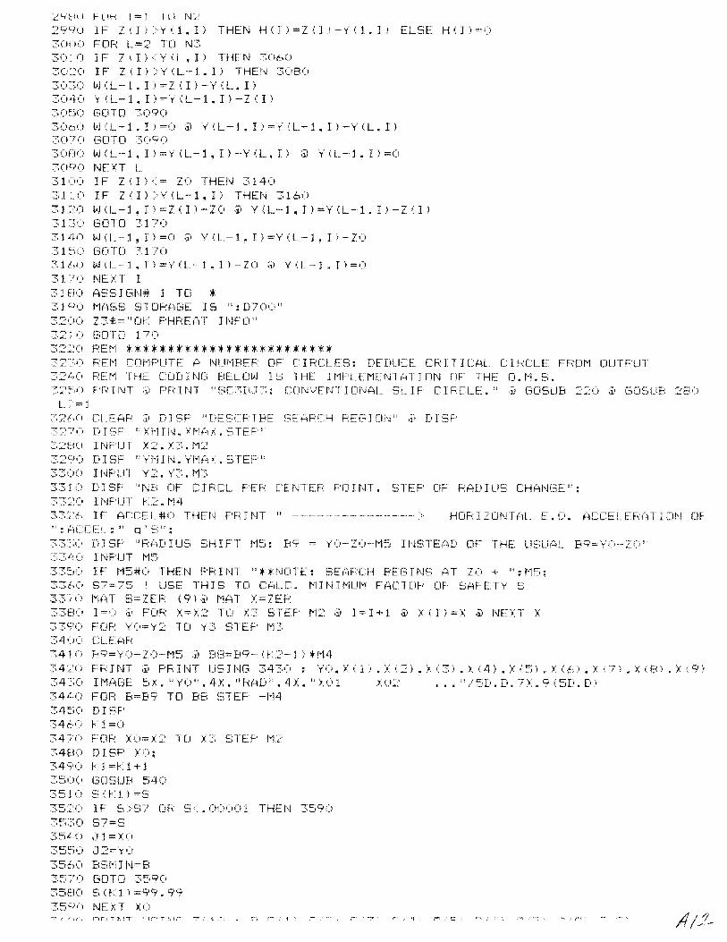
:'::'itIU F LlF: J == 1 I U I'L:'
2990 IF 7(1»'1'(1.1) THEN H(])=Z(])-Y(l.]) ELSE H(1)==(l3()()') FOR L==2' TD N330: 0 1F Z·: I ) -< '1' (L. I) THEt'J 306030::0 IF Z (I) >'1' (L--l. I) THEN 308030~:'0 "')(L-1.1)=2':I)-\(L.l)3()4 0 V (l_ -1 • I ) == Y (L -1 • I ) - Z ( I )30~:;0 ("'DTO ::::,0903060 L·) .:1_-1. I) =0 ;J) Y (L--1. I) =y' (L-1. I) -'1" (L. I)30 7 0 GOTD :::;:09Ci30HO vI (L-1. I) =y' (L-1 ~ I) -.y (L. I) ;J»)" (L-J. I) =03090 NEXT L..:;,1'.. 1'.1 IF Z (I) <= ZO THEN 3140~~,l.(\ IF ZII»Y(L-1.I) THEN 31603 L:~O vj (1_ -1 • 1 ) = Z ( I ) - Z0 ;3) Y (L -1 ~ I ) ='y' (L-1. I ) - Z ( I )31 ~:.(, GOTO 3 J703 J -4 (\ L·j ( L -- 1 ~ I ) == 0 ;J) Y (t. - J • I ) == Y ( L - 1 • I ) - Z031 ~:;O GO TO 317031hO vj(L-1.1)=Y('---1.1)-ZO ;:;) Y(L-l.I)=O31~'C' NEXT I31 HO ASS I C',N# 1 TCl :+31 CiO t'l{\SS STDF:A(~E IS": D70')"3200 Z3$=" en F'HF:E?n I I\JFlJ"321 (; [:iOTD 170
3:2:';:0 F:EI'l *************************32:Yi F:El"l CDI'lF-UTE A NUl"IBEF: OF C I F:CLES: DEDUCE CR I T I CAL. C I F:CLE FFml'l DUTFUT32 L O F;:Er'1 THE CDDHH?i BELOvJ IS THE HIF'LEI-IEI\n(~TIllN UF THE [I.I·1.~3.
32:~O F'F: I NT ;l) F'F: I NT "SC:::'E(J 3; COt'I"iErH I DI'I,:\L Sl. I F C I RCLF." ;J) GOSUB 2:::') ;ii GCJ~;UB2E.lO
'-:;=J32(,0 CLEAF: iii D1 SF "DESCF: I BE :3EAF:CH F:E(;'; I [IN" ;j) D I SF'3 ~: 7 (> DISF "X "1 J 1'1, X 1-1 P, i: . S T E F' II32E10 I NFLIT X2 .:n. 11~:
32Ci O Ii 1SF' "YI" J N. '1"t·,(~ / • STEP"33UO I t'WUT Y2. Y~~;. toe33 J (; D I SF "Nb ClF C I F:CL F'Eh' LEt'HEF: F'O I I-.IT. STEF OF hAD I US CHAI'mE";33:'0 1NFUT r:::. 1"1433~;'\-:\ IF ACCEL#O THEN F'hINT ,,--.--------------... HDF:IZONTAL E.e'. ACCELFhi=iTIDN ClF" : ':'[CEL." q' E;" :.::<:<".' r)]S1' "hAD IUS ~;HIFT t-l~:~: Bq = YO-ZO--t'15 I!'J~;TEAD DF THE U~,U(~L BC",i=\')··20 "~S3bO 1NF'UT I-I::;T:::~IO IF t-15#0 THEN F'F:INT "**NCiTE: SE(~Fd:H BEC:ilN~, AT ZO + ":t-15:3360:' 57=75 I USE TH I 5 TO CI'lLC. 1"11 N I!'IUt'l H~CTDF' OF SAFETV S:::;.3;'(; t'1f=iT S=ZEF: (9);J) "1AT X=ZEFo:33ElO 1=0 ;i' FDR X==)C2 TLJ /3 bTEF I"r:::: ;iJ I = I + 1 ;J) J: ( I ) ==/ ;J) i'lL): T x::::,3';'(; F[lF~: 'y'O'=Y:2 TO y::::; STEF l-r33400 CLE':'\;=;':341 0 E~C;)='1'U-ZO-I-15 ;:i) BEl=B9-- U?-j) tr-1434~~'(i F'F I NT ;i) FF: I NT US I NG 3430 : YO. X ( 1 ; • 'X (2) .x (3) • x (4) • l ,'5) • J: (f:,) • , ("7) • X ,; 8) . j. (C",i)
34:» It-l(-\[3E ~~X. "YO".4X. "RAD".4X. ");(11 }>:)2 ••• ".n:;D.D. TC9(5D.D)34 L O FOR B=B9 TO B8 STEP -M434:;0 D I ~;F'
34&.,0 kl=O34:0 FOF: XO= X2 TO x::::: !::;TEP I·r:::34EiO D I SF' /C';34S'O r,j =r::1+J3500 GDSlJB :'AO:;:;510) E, (k 1) =5
::::;5'.::0 IF 8>57 OF: 5.00001 THEN 35903:':;:::0 5 7 =<::;
35 L.() ~i 1=X(i35:~(! ~J 2= \{ i)
3560 Bi:;t-, I N=B35~'0) GOTO 359U35HO S (r:: 1 ) =S>C",i. 9935 C)() J\JE><T xc;
,". '1', :......."!::_., "'-'.:

3620 NEXT fl3 6~::0 F'R I NT II -------_. - --.- - - ---- ---- --- ---- ---- _. -- - - - - - - ----- -- -- - - - - --- - - -- - - -- - ---- -- - - _. -.- - _ .. - -
------ II ;i) F'F: I ~,n
:?,6,tO NE XT YO36~:-O F'Fn t,n US HJG 3660 ~ S7, a 1. J2, BSt-lll\!2.,61:' ;) HUe) [;f-~ 10 X. II t'1I N Ei = II • 4 Ii. 2 D, II A T X0, YU, B = II • 3 ( 5 D • D )36 7 0 BEEF' 200,250 ;i\ GOTO 17036El') F:EI'1 :+ * ** Et'JD COFF:ECT I Dt,j SUBF:OUT I NE :+:+ *:+31.-_,<;;0 I BEG I t'-J SUB TO CDRRE-_CT FOR nm EFFECTS3700::- I DEL TA=L63710 1 SET UP DEFAULT FACTORS FOR NOMINAl_ (NORMALl CASE3T:O FACTF1=1 ;i) FACTF2=13T\(, FACTC[)== 1 ;j) FACTDt-1= 1374') F':iCTVH=1 ;i) FACTFW=1 ;i) FACTCA=l37~:-0 ~'lF'== 1 ;i) BF'= 1 ;i) CP= 1 ;i) DF'= 1 ;i) EF'= 1 ;j) FFF'= 1 ;i; GGF'= 137 (,-) 1 COI'1F'UTE THE NCJI'1 I NAL AF;:C L.EN(3TH3T'O XB=.~.i:+(X6(Il+X6(I--1/) ;il XC=.:'i*(Xt,(I/+X6(I+1)137E30 IF B2*B2}= (XO-XB)*(XO-XB) THEN YB=YO-SQR (B2*B2-(XO-XB):+(XO-XB» ELSE YB·AI.. 1 El/16/8-337QO IF 82:+82>= ,XO-XC):+(XO-XC) THEN YC=YO-SQR IB2:+B2-IX(I-XCl*(XO-XC)) ELSE YC=PIF: I 8/ 16/8~~:
3800 XF= X6 ( 1.1 ;i) YF=y',~, ( I /38:0 L9=FNHYP(XB.XF.Y8.YF)+FNHYF(XF.XC.Y~.YC)
3[~./(i F;~ ):: ()= :):: i)--l6 I~ I }3Er>-; RYU:='l",)--'y'6 I J)
3840 I CHECI: FC)F F I 1=61 ENTF'V: IENTRV= -1 ---~ 1st ENTRY1 > NON-1st ENTRY
38u:, IT I Unl::':y'= 1 1 HEt,j GenO 3<:;;6038;'0 IENTR'i=:J
38HO I *** FIF:~,T ElnRi ***3800 I CHECK FOR CASE 1-L AT 1-1:?,9('O IF:X:6(]-1)</AL AND i:i:.>II-l )+L6 :::/'/~iL. AI,ID \6,J)-L6/2'XAL (2)ND Xb(ll-rL6.i 2<XAF:HEJj GCiTD 4')603910 I CHECK FOR CASE 2-L AT I39':'() IF Xc, (J) >==~:(:H_ f:iND:x:6 (I) -L.6/=:= /£'\L THEN Lf:'.if3C'39::::0 I F'F:: J In 1I EF:F:CtF': 1~t ENiPY r:\NIi 1\j(Jl 1--L DF: ::'-L II
:?S L, .) I F' F: nH 1I I , / 6 ( I - 1 ) , :-: 6 I I ) • L_ 6<: ,U'lL (-\ F: E: " ~ I • / 6 I I - 1 ) ~ :-: 6 I I ) : L 6 .' ~2: >: (-i L ~ ;:;) F' Fd N1::::8~iO I FETUF:I\J391',() I :+:+:+ t\ICit,j--l!':t ENTF:Y :+ II3ci~.:- (, I C:HEC:r< F·OF. [:r;51:: l--F f:4 T 1+" 139FI" J F:X:6 ( 1 + T-' > X{-if.: ?iND /6 I 1+ j i - 1..6/-::-< /{-iF: rit\JI) /6 ': I ) -L6/ 2 > X{4L Plf\W X6 ( J i +L.61';;', 'U)FHEN GDTD LJ320:?S'<;'O I CHECf FOP CA:3E: :'::'-F: ':1"T I40(,0 I FU: ': I ) -< = :UiF: AI\JD x6 I I ) +L6 /2>== XAF' THEI\J 484('4010 I CHECK TO SEE IF NOMINAL CASE OCCURS4C'~:O IF 1:6 I I) -L6/:::"::({~L riND /6 (J) +L.6/2 xm:;' THEN F:ETUF:t'-140~::O F'F: 1NT !I EFF:DF: DOES t\JlJl FALL I NT(] AI\fy' DF THE kNOWN CATEGOF: I EEi II
4;",LO F'FdNT "I. X6 (1-1',:>:6 (I). /6' 1+1),1_6/2. ::X:{1L., XAf-~: ARE: 1I ~ I ~:X:6 (I-I) ~ X6 (I l: X6 0: 1+1):6/2 :UiL: XAF<: ;i, F'F J1\n40':;0 RETUI::.:I\j40i:'1 I F'R: I NT "------------------ CASE 1--L --------------------"40~n XA=XAL @ YA=YAL40E ,) XB=X6 ': 1 ) ---L6_/2 ;i) YB==YO-SQF: I B2*B2-- (XO- XB) :+ ,XO-XB) l I 8/16/E1340C;(J XD=X6II)+Lh/2 ;i) Y[)='YO-SQP o:B2*B2-(XO--XDi*()(O-XD») '8/16/8::::;41ro XG=XB @ YG=.5*(?(I-1)+zel»4110 AB=FNHYP(XA.XB.YA.YB)41~n A8G=FNDETFIXA.XB.XG.YA.YB.YG'41 :::.(, {.W=ABEi/U 1 X4140 RX1=XO-(X6(I)-L6/2-(XB-XAI/3141 ;:';0
41 t: 041-';.:'41EO41 S":'
I j=: P>:O#O THEN BF'=Fn: 1 /F:XO ELSE BF'=:\)RY1=YO-(YA+VB+VG)/3IF RYO#O THEN CF'=RY1/RYO ELSE CP=UHS==H7+(H1-H7l/(X6(Il-XAL):+IXB-eXB-XA)/3-XAL)IF: H 1 #0 THEN DF'=HS / H 1 ELSE DF'=O .----Re-p-r-od"':'""u-c-ed7""":'f-ro-m---;;
1::- ::'--;--;:' /1 C' best available copy. AI}
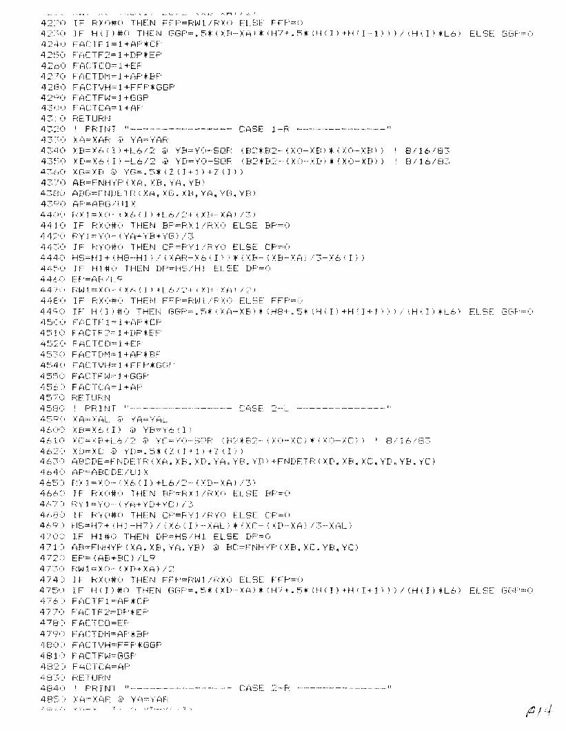
42:?O IF FO'U#() THEN FFF'=F:l'-J1/F:XO ELSE FTF'=O42:") IF H(II#(i THEN (3GF'=.5:+(XB-XAi:+(H?+.:::~:+(H(J)+Ho'I-l)))/i,H(I):+L6jELSE GC~F'==O
4240 FACTF1=1+AF'*CF42~:;O F'ACTF:?== 1+DF':+EF'4::(~)') FrILTCD:=: 1 +EF'42:7 0 FFiC'TDI"'i= 1+FiF':+BF'4::{30 FACT'v'H= 1+FFF':+ GGF'42QO FFiCTFlJJ= J +(3(3F'4:;(;0 FACTCFi=1+AF'43: 0 F::ETUF:N43:::0 I F'F: nH ,,-------.--.----------- CASE 1-F: --------..----------.--"43:;':; :):A=X{.:,F;: ;;) YA=YAF:4340 ,:B= Y t:' .; 1 ) +'-.6/2 ;iiy'B=YO-··SOF: .; B::':+B:;'-- (>:0- XB) :+ ,. >:0·- XB) i I 8/16/834::::'~)0 X[0= X6 i I' -L6 /2 ;ii YD=y'O-S(}F: ': B=::+ B::- ( X':!-- XD, :+ i :~: (1- XDi ) E3/ 16/ fl::;'431',0 XG=XB :;'; Y[~=.~;:+(Z(I+j)+ZIJ)
43~ro AB=nJHYF' (XA, XB, VA, YB)43tiO (iBG=f=-r'JDE:n;: I XA, XE'. XB, 'y'r:). Y(3. YB)43':iO AF'=(~B(J/U1 X44,:,0 H Xl ==): 0- ( X,~, i J ) +L6 / '2+ ( XB- XA) .1 :~)i
44JO IF RXO#U THEN BP=px1 / RXO ELSE BF'=O44:,:'0 F;:Y1=YO····· ';YA+YB+y'Ei) ./344:::;') IF HrU#O THEN CF=F:Y 1 /RY(i ELSE CF'=O44~0 HS=H1+(H8-H1)/(XAH-X6II))*IXB-(XB-XAi/3-X6llil44=;() IF" 1-11.#1,) THE:f\J DF'=r-iE;/H j E~L.~)E [)F':=f)44tO EY=PiB/L_94·<1 -; () F·:l·J 1 =--= X()-- o'l6 ': Ii +L6 / '2+ ( X1(- X(iii ::= l44E:O IF F:XC'#O THEI\~ FFF'=F;:Wl/PXO ELSE FFP=O44(;0 H: H,. J ) #0 THEN (3[:iF'=. 1::", >Ji->::BI:+ IH8+. ~;* IH; I) +H; J+1" )./ (H I I:; *L6) ELt:-;[ f3f3F'=045(0) Fi~Cn~1 == 1+'AF'H~F'4510 FACTF2=1+DP.EP4~~:-: (0 FACTCC:I~' 1+EP4530 FACTDM=l+AP:+BP4540 FACTVH=1+FFP:+GGP4550 FACTFW=J+GGF'456(i F~lCTCf~==1 +AF'4:::,70 F:FTUF:N45El(o I F'F I NT ,,----..- ...-----.------.--- CA~T ~':::-'L -----.---------.----"it =:i 9 ':. l (\~, \ f~ L_ ;;'y' (~,=/ {Cl L4600 \8=X6o'I) @ YB=Y6(I'461 ':' XC==;.: B+i_b/:':: ;ii YC=y"'-·i3C'P i FC;.B2- I>: 0- \C) • ': ;.: O-lC)) I 8/16/(334620 XD=lC @ YD=.5:+(Z(I+l1+Z(Il)4630 ABCDE=FNDETR(\A.XB.XD.YA.YB.YD'+FNDETF(XD.XB.XC,YD.YB.YCl4640 AP=A8CDE/UIX465:=) F~Xj=Y()"-(X6(I)+L6/2--(XD-XA)/3)
4660 IF RXO#O THEN BP=RX1/RX(o ELSE BP=O467) RY1=Y(o-IYA+YD+YC)/34680 IF RYO#O THEN CP=RYI/PYO ELSE CP=O4690 HS=H7+iHJ-H7)/(X6(Ii-XALl:+(XC-(\D-XAi/3-XALj4 7 00 IF H1#0 THEN DP=HS/H1 ELSE DP=O471" A8=FNHYF' (XA, XB. YA. \r'b) ;;) BC=FI'JH"y'F' (XB. XC. YB, YC: l472) EP=(AB+BCI!L94TY' F;:L<Jl =\0·- <lD+\A l /24740 IF RXU#O THEN FFP=F:Wl/RXO ELSE FFP=O475':) IF H'; 1) #0 THEr-J GC";F'==. 5:+ (nl--Xi~):+ iH·,'+. ~;* (f--''; I I +H ': 1+1 I») / (H (I I *L6) EL:=:;E GC,F'=O476' FACTF1=AP:+CP4Tl') FACTF:~'=DP*EF'
478) FACTCCI=EP4 -;;'(:;'" F {4CTDI'-i=r:iP :+BP480) FACTVH=FFP:+GGP481 ,) FACTFlJ,i=GGF'48:::' J F ACTCA=AP48:~:") F-:ETUFt\J484') I PF: 1NT ,,------.------------.---- CriSE :2-F: ---------------.-.--"485) XA=XAR @ YA=YAP/1 C:-. ,", ".'"i' ; __ -.... "·..'·r; _._.' .,-", ;f)/4
I·.' "

4880 XD=\C @ YD=.5*(Z(I-l)+Z(I»4890 ABCDE=FNDETR<XA.XD,XB.YA.YD.YB)+FNDETR(XD.XC.XB.YD.YC.YBI4900 AP=ABCDE/U1X4910 RX1=XO-CX6(!I-L6/2+(XD-XAI/3)49:2') IF F(~O#O THEt-J BP=RX 1 /RX') ELSE BF''=C1i4930 RY1=YO-(YA+YD+YC)/34940 IF RYO#O THEN CP=RYI/RYO ELSE CP=O4950 HS=Hl+(H8-H1J/(XAR-X6(I)1*(XC-(XD-XA)/3-X6(J»4960 IF H1#0 THEN DP=HS/H1 ELSE DP=O4970 AB=FNHYPIXA.XB.YA.YB) @ BC=FNHYP(XB.XC.YB.YCI4980 EP=(AB+BC)/L949~0 RW1=XO-(XD+XA)/25000 IF RXO#O THEN FFP=RW1/RXO ELSE FFP=O501(1 IF H(J)#O THEN GGP=.5*(XA-XDl*(H8+.5*(H(Ii+H(I-1»)/(H(I)*L6) ELSE GGP=O5020 FACTF1=AP*CP50:~O FACTF2=DF'*EF'5040 FACTCO=:oEF'::;0:50 FACTDr'1=AF'*BP5060 FACTVH=FFPtGGP::,O"/() F(iCTFI.>J=GGP50:30 F:f~\CTCA=AP
:',090 F:ETUF:N51 (I() ~ I r"'lF'LIT f-iC)F~~ 1 ZCH,rr AL ACC:EL51 t)::1 CL.E?iF5110 DISP "ENTEF: EAFHHQUAkE HOF:IZClNTAL ACCELEF:ATIO'" IN q UNJTS":;;:i JNF-'tlT (iCCEL511~1 Z5$="Df ACCEL"::,1 :".:':' GCnO 170
4/

10 I **' SUPERSTB : HAS BEEN STREAMLINED**** : RENUMBERED ON MAY 2020 PRINTER IS 401,132 @ PRINT CHR$ (15) @ PRINT @ PRINT30 PF: I t,n "SUPEF-:STB: \"JEF:E; I ON 30-ALlC3-83: E. Q. CAF'AB I L_ I TV. SL I CE S I Z I Nt, T I ED HI F<lT LENC3TH" ;ii PF: I NT ;i' PI:;: I NT35 I AUG30 83 CHANGE: L12 WAB BET TO ACCUMULATE IN TWO CASES40 OPTION BASE 150 CDt-l Y (=;,400) , L'J (5,400) , Y6 (400) , Z (4()0) • Z 1 (400) • SHDF:T X6 (400) , yq (40() , H (400) , F(4 O() >
60 CD,..l SHORT CH (5), [32 (5), T (10) ,C (10) ,\/1 (10) ,\i:: (5) ,\,':3 (5) ,\/4 (10)70 SHORT L(20)80 DIM TITLE$[80]90 :Zl~i=""W:l EMBf,,..1T II\IFO" ;]) r:9$=:"O" ;il Z:::,$=="ND PHREAT INFO" ;]) Z::::$=="NO SDIL INFO';i) i='$=" (i II ;i) Z4$=" NO TITLE" ;ll Z::,$=" ACCELEF,:AT I ON == [)"100 Ol'~ rFV# 1," I. Et1BfJ-1T" (3ClTD 476011') [11\~ fE''l''# ';C',":C;) SO I L" (:,;OTO =;60120 ON rTY# ::::;. "::::.) PHF:EAT" (30TD 49001 :y) ON rEy# 4." 4) TITLE" (-;[lTD ~~;:,iO
140 DN fTY# =;." 5) CCH'~')EN " (30TD 4350l~)O ON fFy# 6. "6.' ELL_IPS" f3DTD 72('16') fJr\J t:::E\/# '7 II II ~l) [:'y'L., 1 t\j[; II C3CJTCI 56 7 ()
1}(1 CIt') fEY# El." 8 i D I SF'" GDTCi -:":7,~,(;
18(; Ol\i f:EY'# q," 9 l ACCEL_ "(301 () 7::,')('19(' ON f:::EY# 10." 10) DETAY" C~CrTO 6(,4(,2(,,; G::::'==62. 4 ;i) ACCEL=()21 (j 1'1?)Sf:; STOF:?~[iE I!:; ": D?(H'"2~>J C~l EAR ;j) f'EY LABEL ;ii DI:3F' "cm'r! :::~=:O" ;il DISF'2::::';) DISP 71$ ;i) DISF' Z2$ ;i) DISF' 7:::,,$ ;j) DISF' Z4$ ;ii DISF' 75$ ;iI vJPJIT 5("-'":::'4(i 1:3[1TO 220250 DISP "E!'HFFi: TITLE ?'~I\iL' TDD?Yy'S"S IH1TE."26" I !'!F'UT T I TLE$:~7(i Z4$="TITLE IS H)"28(; Genu 2:20
=~ 9 U FE: t-l *' *' *' *' *:+ ***' :+ *' :+ *:+ :+ :+' :+ :+ :++ :+ :+ :+ ;+ :+ :+ :+ ;+ :+ :+ , ;+ :+ :+ ;+:::'00 F'F: I NT ;j) F'F I NT II SPEC I F 1 CAT 1[)NS FCiF: rH 15 F:LJN"310 F'F: I NT ;i' F'Fd NT T I TLE$ ;ii F'h J 1\11320 PH I NT II SD I L F'F:CiF'EF r I E~;: FILE ". F$,::<,', , F'F,: I NT "Et%ft-1T {3FDI1ETFY: FILE ": F'd;:::::40 F'F: 1NT "PHF:EAT J C f3UFFr;CE: ": ;i" IF p,,;= II 0" THEN PF: I NT II NONE" ELSE PF: Ii'H II FILE 'P$:" SLJF:FACE:":UC;>35(1 F:ETLJ~~I\J
';'0" F:Et-l * * * :+: *' *' *:+ *' * *:+ * * :+:+ *'37(1 REM GENERATE BASIC CDORDINATEB USED BY CONVEN.,ELLIPSE AND CYLINDER:38(, F[IF.~ 1=1 TCI f\f~~
:::'8,> Y6 ( I ) =040(1 Y9 ( I ) =041( Z(I)=ZUit:2(14Y4 l J.(,
45(
47(
48':'49(~i()(l
:_, j (
C:::'-"',-,
FOR Ii=" 1 TO I'CZ ': I ) = Z ( I ) + Y m. I l +vJ m. I )NE\T DNF:xT IH==4()[) 1SF' II EL_L_ I F'. CC)[lF;:['. X(>= II ~
I NF'UT XO[; I SF' II EL.L I F>. C[t(JF;:I) n Y(~=!I:
INPUT YODTSF' "SLIF' F:ADUJS B =" =TI',/e,,:T D If I G
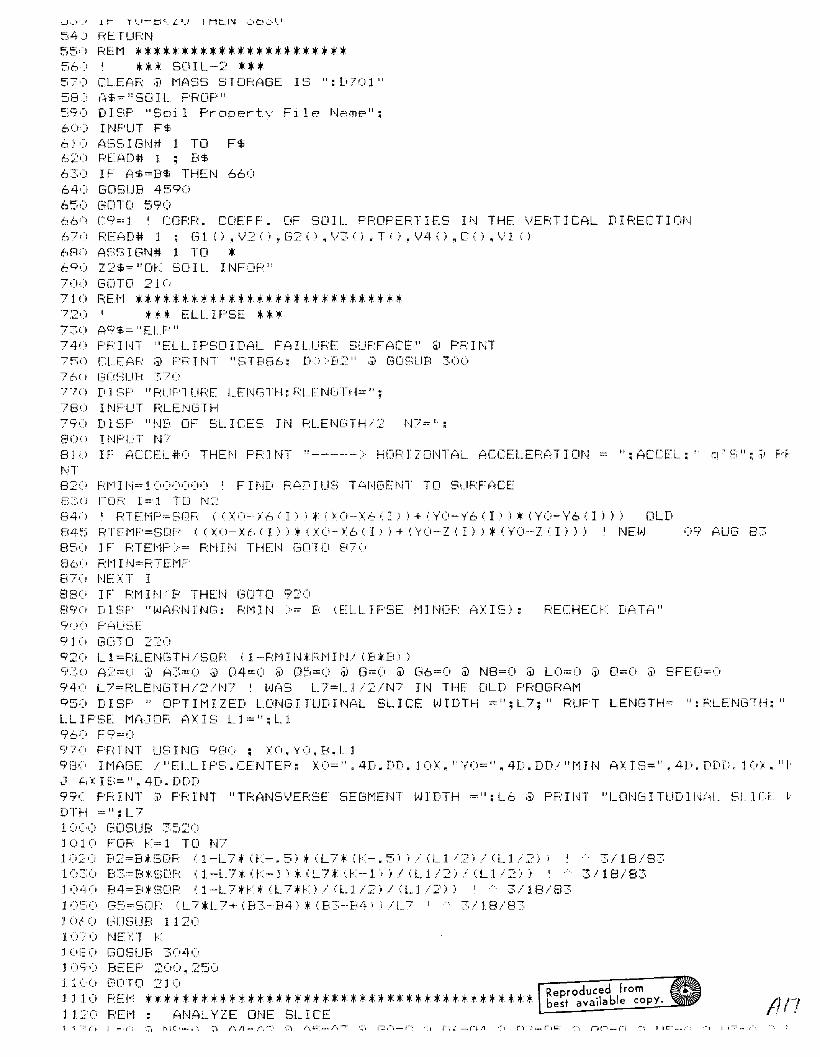
" : (4CCEL;" CI' (:";" : 'J) F'F
~J._:,I._! 1 r I'.. J--~·:·. L ',_' I Mt:.I'.J .':';.C:) .•:':-'.)
54) RETURN55') F:Et1 *:+: * *:+: *:+::+::+: :+: :+: *:+: :+: :+::+: :+::+::+::+::+::+::+:56) I :+:*:+: SOIL-2 ***5F> CLEAF: ;i) t'1ASS STOF:AGE IS ":[i701"58:! (;$=" SD I L PROF'":',9,) Dlf,P "Soil Propertv File Ne:\me":60) I NPLJT F$61') A~::;!:~ I Gt\I# 1 TO F$62') REF\[)# 1 : 8$63,) IF A$=B$ THEN 66064,:, GDE:;UB 4590650 ["'OTO 59066', C9=: 1 I COF:FL COFF F. OF SO I L F'F:OPERT I ES I N THE VEF:T I CAL D I F:ECT I Ol\~
67,) F:EAD# 1 : (31()~~J2().G2().'-/::;().T().\.)4()~C().~..J1()680 ASSIGN# 1 TO *e:;.o Z2$""" Dr:: SO IL_ HWOH"7(1) GOTO 210710 RFt'1 :+: *:+::+::+::+: *:+::+::+:+::+::+::+::+: *:+::+::+::+::+::+::+::+::+::+::+::+::+:T2U I:+::+::+: ELL I FSE :+::+::+:730 A9$="EI..P"740 F'HHn "ELLIPSOIDAL F(HL.UFF SUF:FACF" ;J) PF:INT75') CLEFiF;: ;il F'F' I NT ., ST886: D') :D~:" ;il GOf;U8 :30(.76' J (3CiSU8 370771) D I ~:;F' "F:UF'TI,JRE LEI'j[.,TH: F:U':'::I'-IGTH=" :7W) INPUT F:LENGTH79'i DIE,P "NFi OF SLICES IN F:LEN!3TH/2 N7=":8U" I NF'UT N/81 Ii IF ACCEL,#O THEt\~ F'R J tH "-------:- HeiR I Z(Ji\~H1L ACCELEF:AT I ONNT82U F:t'll N= 1000000 I F H1D F:AI:n U!:, HiNC3EI\!T TO SURFACE8::.t.i FDF: 1= 1 TD N284 ( i I F: 1 E: t'1 F' == !:; 0 F;; «\ 0 - l6 ( I ) ) :+: ( \ 0 -- / 6 ': J } ) + (y' 0 - V6 ( Ii) :+: (Y 0 - 'y' 6 ( I ) ) ) 0 L D84':':' F::TEI'1F'=SDF: 0: (i<0-/6 (I) ):+: (/o->;t.., (I) ) + (y'(i-Z (I) ) :+: ('1"0--7 (I) )) I NEt}J 09 AUG 838:",(i J F F:TEt'lF' >= F:t-j I N THEI'~ GOT Ci 87 (I
86(0 F:f'1 I N:=F:TEI-1F'Eeu NEXT I88U IF F:t1 I I\l B THEI'~ GOTO 920Fl9,) DIE;F' "L'JAF,:NING: F:1'1It\~ :-= B (EL.LIF'!:'E t'lINDP AXIS): F:ECHEU::: D(4TA"9()(:' F'ALISE'
91 (; (3ClTD 2:20920 L1=F:LENCHH/SDF: (1-F:t'1IN:+Fn'1HLi (B;fB) )930 A '?== C' ;i) A3:-;:: 0 iii 04=0 ;i) Q:=,i=O ;iJ G=(' ;j) ["6=0 ;i) N8=O ;il LO=O ;i) [1=0 ;i) SFED=')94(1 L7=F:LEI,~C.':;TH/2/1\1'7 I L.J{~S L7=U /2/1'-1'7 ll\~ THE OLD PROGF:Af'1950 DISF' " OPTH1IZED Lm\H3ITUD1I'JI~L SLICE !.'JIDTH ="~L7;" PUPT LENGTH:: ":F:LENCHH;"LL I PE.;E t'1FiJOF: AX I~; L 1==": L 196(1 FC.~::.:()
97(, FF::JI\n USING 980 : >~(I. YO. B, L19f3C' I1'1'::~GE /"ELLIPS.CENTEP: XO=".4D.DD.10)(.""t'U=:".4D.DD/"t1IN AXIS=".4D.DDD.1(1i. "t,\-1 f:,XIS=".4D.DDD99(' PRINT ;j) PF:INT "TF:At\~S\JERSE SEGt'1EI\H !.'!lDTH =": L6 ;ii F'F;:Hn "Lm~GITUDII'~{il_ SLl[T L'DTI-! =":L71OCO C.,ClSUB 3;::i2(i1010 FOR r=l TO N'710:0 B2=S*SOR (1-L7:+:(K-.51:+(L7*(K-.511/(Ll i 21/(Ll/2) I I A 3/18/831 (':-':,(1 R::,:=B:+ !:,DF (l-L"7 * (r-1 ) :+ (L 7:+: (r -1:; ) / (L 1/2) / (L 1/2) ) .. 3/18/83lOll,:) B4""B:+:~3[iR (1-L7n:t:(L7;H:)/(L_1/:')/(L1/::::'») ... 3/U3/831(i::;(' G~:'=SOP (L7:+:L7+ (83-84):+ (K":--B4» /L.7 I :::;/l.8/8~~
1 0,;0: 0 GClSlJB 11201'0i';;0 NEXT r:1Uf: 0 GOSUB ::::;'::;4(,:l ()S:(~ BEEF' 2('(;"1 25',)
11 C'>:' cnro 210 Reproduced from1110 FEI-1 *:+:***:+:******:+::+:**************:+:+**:+:****:+::+:**:+: best available copy.1 L» PEI'I ANAL V ZE ONE SL I CE /117

==1..
1140 1ENTPi=-1 ;i) I PF: I t'H K:;: B3: B41150 FOR 1=1 TO N21160 IF B2*B2«XO-X6(1»*IXO-X611» THEN 1180 I
1170 YbII)=YO-SQR (82*B2-(XO-X6(I»*IXO-X61I»)1 1i30 FO 1J ) =0119,) I'JEXl 1j 200 I J F F'$=" I)" THEI'~ 1750
3/18/83~;/ 1E3/8~
..... ~::./ 18./8:?;
121 0 ROCnCH~:=-'l
1220 FOR 1=2 TO N21230 P4=SQR (IXO-X6II-l»*IXI)-X6II-l)I+IYO-ZII-l»*IYO-Z(!-I») 3/18'831240 P6=SQR I(XO-X6II»*IXO-X6II»+IYO-ZlII)*IYO-Zl1») A 3/18/831250 IF P4{B2 OR P6<B2 THEN 12701260 GOTO 1550 I SLIP CIRCLE IS ABOVE THE iTH SLICE1270 IF P4~B2 OR P6}B2 THEN 13301280 I CASE OF LATERAL HYDR LOAD FULLY BOUNDING THE iTH SLICE1270 01=.5*17(1)+ZII-l» @ 02=.5*(711)-711-1»1300 FI)II)=-I.S*G3*IHII)*HII)-HlI-l)*HII-l»*L7:+IYO-Ol+02/3»1~, 1i) GOTD 1~,~;i)
132l) I THE FOLLOWING IS THE REFINED INTERSECTION SCHEME:1330 MM=(ZII)-ZII-l»/L6 I SLOPE M1340 BB=ZlJ-l1-X6II-l):+MM ! INTERCEPT b13':;0 BBB= (1'11'1:+ 8B-I'1"'1:+ 'fO- y, 0 l / (t'l"'l:+ 1'1"'1+ 1) I .. :;:,/18/8:;:,13,:.0 eTC= 1XO* \0+ ('y'O-BB I *IYO-BB) -B:2*£1;') ./ <:2 *I,.·1t·l:+t·lI·!+ 1) ) ~~; /18/8:::::1370 ROOT1=-BBB+SQR IBBB:+BBB-2*CCC) 3/18/831~)E)(1 RDOT::>=-BBB-SDP IBBB*BBB-2:+C::CC) ::::,/18/8::;1300 MEAN=IXbII)+X6II-l»/214,)0 IF IMEAN-RODT11:+IMEAN-ROOT1){IMEAN-ROOT2\:+IMEAN-ROOT2 1 THEN P5=ROOTI ELSE~:;=F:C:)(JT2 13/18/831410 H6= Z I I-I .i + ,; Z I I ) - Z I 1--1) ) / I X6 I I ) - X6 ; 1-1 ) ) :+ IP5- X,~\ .; 1--1 ) )1420 IF R001CHk=1 THEN GOTO 1510 @ 1 IF P4{= 82 OR ROOTCHk=1 THEN l73014:~O 1'r'6 I I-J) EXCEEDE; Z I I-I)l'lAO Cil:::.5l'?'I.i+H6l ;i'D2=.:H'Z'])--Ht,)1'1';:'0 H7 =H • 1-1 ) + (H • I ) --H , 1-1 ) ) / I X6 • I ) - >: 6 ( 1-1 ) ) :+ 1P5-;': 6 , I-I ) )lAc)') FO':I)=-1.5:+C33l1HII):+:H'I)--H7:+Hn:+L_7:+'YI)-Dl+02/3» 1·····3/18/8314~'0 XAL=P5 @ YAL=H6 I MDH 2/28/83 -->NEED THESE FOR END CORRECTIONS14UO ROOTCH~:= 114 c1 0 [,[lTD j ~,50
15"') I Y61I) EXCEEDS ZII)1510 01=.5*IZ(1-1)+H61 @ 02=.5:+IH6-ZI]-I»1~:;:?() HE3=H i 1-1 ) + IH ( 1 ) -H 1 1-1 ) ) / ( X6 .: I ) .- X6 ( I -1 I ) *'F'5- / 6 ( 1,-1 ) )J ~,» F0 .; I ) =-- ( . 5 * t3~:, * (I-JEl *H8·- H ( I -- I; :+ H ( I ._- 1 ) ) :+ L7,: Cy'0 -01 +D::: /:::;» ! MDHISLe, XAP=F'S ;i\ YAR=H6 I ,.'iDH :?/:~8/8~:~ -- .:-USE FOF: END COF:Fi:EcTI ONSj 5·.~;(; Nt: ,. T I
1=~60 FOR 1=1 TO N~:~
1570 F:=O ;ii F:9:::()15EO HI =H ( I ) + Z0 ;il "l\,l(.1J=H ': I ) :+G~;*L.6 lL7 ;i) "1=" I "1DH :2/28/EI31590 FED=O I E.O. MOMENT SUMMAND16(0 FOR D=l TO N31610 H1=:H 1+W •D, I )16~:0 NEXT D16~:'0 DO=SOF: •• XO-):6.Ii):+O:0-/6']»+C·y'(;-Z'l»:+:IYO-Z.Il»)1640 IF DO~B2 THEN 16601650 Y6II)=0 @ GOTD 286016tO IF 1=1 THEN 36301670 IF J=N2 THEN 363016EO Hl= (f-il-Y6' I»:+: lHI >Y6 (I) )
3/18/8::::,
j 6(=t() ~AjU==(,
1700 7.1 (I)=ZII)-Y611) ;i; U1X='i1710 IF A9$# II CYL. II THEN 21 <:;i(,
1720 u=c, ;1) LC=O ;j; /5={l6(1)·-XO,*'X6(1)-XO)17~0 FOR D=l TO N31740 7. j ( 1 ) = Z1 1 I ) -own17~0 I BELOW:DO-}DRY~ D2-}WET1760 DO=2*D-l @ D2=D*2 @ Dl=DOi -r··: ... ··• Tt:" \./ I'r. 1'", .-1-', -rut:"t·,: 10/lj-j
"'1DH 2/28/83 3/18/83
;t}j?f·
I '\.L:. J.' >', L J. ',J. ,1 I nCI" It::'i/I>~.I
1/90 1"11==EiliD)*Zl(U*L6lL7;j) Ul=Zl(UlL6 ;:i) UIX=UP:+Ul1800 F: 1==\;:::: (D) :+r'll1810 EOT=Mll(YO-Y6(IJ-Zl(I)/2) @ FEQ=FEQ+EQT @ REQ=V2CDJlEOT*V2(D)tEQT3
····3/1 Ei i
1 8~:>i F:9=F:9+F:EO1 8::::;0 ,: 6 = S[I F: (X 5 + ( Y(I - Z ( 1 ) + Z 1 (I ) /2) :+ eYO -- Z ( I 1+ Z 1 ( 1 1 / 2 J J I / 3 / 1E( / El31840 M==M+Ml @ U=U+Ul*C(DO>lX6H=J~,i-) F'=R+F:l:+F:l ;i) U2=U::::+\}J (DO) HI1*CWO:, *X6 I I"1DH. FEB09 83 !"3i18/83 I (4UG-:~1 Er:18=d I OLD 18:::;0 F:=R+Fl HO ;:i) U2=\)1 (DO) lUi lC (D'.) :+X6 ! r'1DH, FEB(i9 83 '::::/ 1f3iEL';1860 GDTO 25801870 Ml=Gl (DI*V(D,IJ:+L6:+L7 @ Ul=Y(D,IJlL6 @ U1X=U1X+U11880 R1=V2(DJ;;Ml18~O EQT=Ml*(VO-Y6(IJ-Zl(IJ+V(D,IJ/21 @ FEQ=FEQ+EQT @ REQ=V2(DJ*EQT:+V2(DI'EOT····3 ../18/8319:;0 F:9=F:9+F:EO19 lOX6 = E; 0 F: eX5 + ( YO ..- Z ( Ii +'1" eD, I ) /2:' :+ (Y 0 -- Z ( I ) + Y ( Ii, I ) /2) ) .:::;. / 18.' 831920 M=M+Ml @ U=L!+Ul:+C(D01:+X61930 F:=F:+R UP 1 ;ii U2=U2+V 1 (DO J HJ 1 H: (DO) :+ )(6 I r-1DH, FEB09 83 /3/ H3/83 I AUC331 F
"3/I8/E
1940 21 eIi=21 (Ii-TeD, I)1 9~~,O 1 F: t'J eO. I ,; =0 THEI·! 214"19,:.,(i IF vieD. 11<21 (I) 'THEN 206(.19' 7I' t-n = ( C:;:::: ( D 1+ (3:::) ;; Z 1 ( I 1 ;; L 6H_ 7 ;j) U 1= Z 1 ( I ) :+ L 6 ;i) U 1 )<; = U 1 X+ LJ 119HO F:l=I./3 (L») *'1119c~0 EOT=Ml*IYO-Y6elJ-ZI (1)/2) @ FEQ=FEQ+EOT @ REO=V3(O):+EDT*V3eD.lEOT ' ~3/18
:::'000 R'j'=P9+F:EC)20 J (; X6=SQR e) :-,+ (''1''0- Z eI ) + v (Ii. I l + Z 1 ( 1 ) /2) :+ e'1'0-- z eli + Y eD. I " + Z 1 ( I ) "2 l );:0:::0 t'l=t-l+r-l1 ;i) LJ=U+U 1 H- iD2' :+ xC:.20::!,0 F;:=F+Fl*Fd+:::::+F:litSDF-: (F;:,:+C9 ;i' U:::"=LC:+\)l dYZ):fU1lfC(D'21*Xt) I 1-1DH FEBUc,> 83 '3/1f204i) [) 1=[J:-2 I L'JET20;':;0 GOTD 2:::if3U2 () \,,::, () r"'11 = ': [,:0' ( [) ) + [-1?') *l.LJ .; f). J ) *" 1_ t) *L 7 ;;-, LJ 1 == lJ.) ( I) &; 1 :; *,-_ ,f:.) ;j) Lil l.. = L.ll X+ LI j
'20/'0 F: 1=\)3 .; D l ;; r'll20EiO EOT=Mlt I YO-Y6eIl-Zl eI1+W(D.II/2l @ FEQ=FEQ+EOT @ REQ=V3([JltEOTlfV3(Di*EOT
3/1 E3i8-'::;:!O(~'O f':9=R9+F:FTl:2 1 .::' 0 \ <':> = S () F,: .; X5 + (/0- Z 0; I ) +/ ( D. I ) + t-J ( [', 1 ) / 2 I t ({0 -- Z i, I l + V ( Ii, I .! + (.J ( D. I ) / 2 l\ ·····3,/ 18 I 8 :2110 M=M+M1 @ U=U+U1*CeD2l*X621::0 F;:=F:+R 1 IF: 1+:::: lfF: 1 it~3C'h (F:) *C9 :1; U2=U::::+') 1 (Ii2) *U 1 H: (D'2 i :+:x6 I t-1DH FEEiOc;,; I .:,~, /1 El:::1:::0 D1=D::::' , t-JET::::140 vJ(I=V.J (D, I)21:'.0 NEXT Ii2160 D=[)-l2l7() GDTD 25l~i)
21 ElO un =0:? 190 FDF: D= 1 TD r'n2200 D1=2*D-l I MAKE OFY2210 Z 1 ( I ) =Z 1 ( I ) -L'JO2220 IF '1'ID.l)=O THEN 2370::230 IF 'y W nIl <Z 1 ( I) THEI'J 2::::,1 C,2240 M1=Gl (Dl:+:Z1(I)lfL6*L7 @ U1\=U1X+Zl(I):+:L6 ' MOH, 2/28/8327:50 F:l==',)2 (D) Hll2 :2 "'~, ) "-'1 == r-j-t- r-l 1227) R=R+Rl*P1+2*Fl*SQR eRi*C9 ' A3/18/832280 EQT=Ml:+:o;'1'O-'1'6';I)-Zl(I)/2J @ FEO=FEQ+EOT @ REQ=V2(D):+:EQT*V2(Dl*EQl I ~3/18
2~~·'9)
'2:S j ':i
R9=f;:9+1:;:E_Ci
[~DTD2::='i80
Ml=Gl ([JI*V(D,Il*L6*L7 @ U1X=U1X+Y(Dnll*L6 I MDH. 2/28/83F:l=')2 (D) *"11"-I=t'1+!'11
,....17/1,-·, -.>-:;,: 1 C Lj"::
.... '-' , I '1',..1 '1I',.J '''':'_IT'j ,I :,,\-.",,;,,'1',. -.,J"': IT'\. . .. '.: J ',_.' ,-"._,
2350 EOT=Ml*iYO-Y6(1)-Zl(ll+Y(O.Il/2) @ FEQ=FEQ+EOT @ REO=V210l*EOT*V2iUI*EOT '····:3/ j 1:)/832360 F;:9==F9+FED2370 71/1)=71(1)-'1'([>.1)2380 IF WIU.Il=O THEN 25502390 IF (.oj (D. I) <Z 1 (I) THEt,j 24B()2400 Ml==(G210l+G3)*Zl (Il*L6*L7 @ UIX=UIX+Zl (I)*L6 I MOH. 2/28/832410 F:l=\.J3 (Dl n11:::420 1"'=1"+1'112430 R==R+Fl*Rl+2*R1*SQF (R)*C9 I A3/18/832440 EQT==M1*/YO-Y6(I)-Z1 (I) ~J @ FEQ=FEQ+EQT @ REQ=V3CDl*EQT*V3(Dl*EQT I ~3/18·
32450 R9=R:9+REC"2460 Dl=D*2 I WET2470 GOTO ::5802480 Ml=CG2(Dl+G3),WCD,Il*L6*L7 @ U1X=U1X+W(D.Il,L6 I MDH. 2/28/832490 R:l=V3 (D) *1"125)0 1'1=t1+t-112510 R=R+Rl*Rl+2*Rl*SQR (R)*C9 I A3/18/832520 EQT=Ml*C'1'O-Y6(Il-Z11Il+WID.Il/2l @ FEQ=FEQ+EQT @ RED=V3IDl,EQT*V3(Dl*EQT'3/18/Fe,2530 R:9=R9+RED25QO Dl=D*2 I WET255() vJC;==W ( D. I )2:':,Yi NEXT II:27::.; 70 D=D-l25;:)0 bCiSUfl 60902St') DEF F j\JH\T ( X':''.J. XFt. "rA ,if( i == ~:;OF: « X~i-- XB 1 * (X~i- XB 1 + Cy'{.i-YB I * i '1'Fi-YBJ'3,/ 1 Fli t l 326)0 DEF FNDETRiXA.XB.XC.YA.YB.YCi == .5* (XBtYC-XCtYB-(XA*YC-XCtYAl+XA*YB-XB*YA,:::'610 FF: J CT 1::.' (t"*FACTF 1+t-")lJ.JlFACTFI"J' * 'YO-l6 ( I) ) /C.,5*T i D 1;2620 FRICT2=-iHllG3l82tL9*GS*L 7 lTlDll*FACTF2l @ AO=FR1CT1+FRICT226.~;O I PRINT "FACTF1.F(iCTFI"LI:::(iCTF:' (;R:E":FAC'TF1~FACTFl.--J:FACTF::':"FF:ICT1, FFnCT2 ~
E: " : FF: I CT 1: FF I CL:2640 I F ~iO' 0 THEN AO=O2650 OO=SOR (R/iM*FACTF1+MVWtFACTFW)!/M*FACTF1+MVW*FACTFWl+V4(Dl'*V4(D]\) 1 .•~,
826,SO Al=L9*L7H; ([11) *B2*GS*FACTCD26 7 0 01=\/1 (Dl.'26130 DEN=t·'*FACTor·,+t·NlJ.J*FACT\,lH26~~10 C.,1=DEN*(XO-;'6(I)i+FED*ACCELi+F~lCTCA;j) IF ABS (Gl».OOOI THEN GelTU 271027')0 09='0 ;i) GDTCi ~~72') I I'lf:'1Y 19 1~: ~ (; 1 PI"27LO Q9=SQR (R*IXQ-X6II»*(XO-X6iI»+R9*ACCEL*ACCEL)/ABS (Gl) I CHNGD ON 3/j2/E
"'::::;./18/8:::;2720 IF ACCEL=O THEN GoTo 2750=:T~O T09=SDR (P) lABS (DEN)::'740 IF 09"2*ID9 THEI\I D9=2*T09 I Boe;us. BUT l.--,IH~H CAt'J l.--JE D[l-::'27~5() L=L_+L_9*FACTC:[j::!760 I PRH..n "1..9. FACTCO. LO*F~iCTC[l. I.. AF:E: ":L9=FACTCC)=L9*F~~CTCO=L~:T?C' N9==N9+ 127130 SFEO=SFEO+FEOlFACTCA ! USE TO COMPUTE q LEVEL AT WHICH FS=1:::790 IF A9$#"CYL" THEN 28102800 U3=U3+U*FACTC:A ;i) US=L!:':j+U2/U ;3> UO=UO+U1 X*FACTLA28LO A2=A2+AO @ A3=A3+Al2820 04=04+00 ;1; 05=05+C! j
28:)0 REt'1 NOTE CHANGES IN C!9 AI\JD G I
2840 G=G+G 1+FO i I) ;j) O=C1+D9 ;j) F9==F9+FO l J) I ;j) PR I NT "* if I. D9. Q: ": 1= C'9: Cl ;1' F'R ll,n
:'8<:\':; NF XT I28'70 IF V#l THEN 291028l:l0 N=IP (L/10)2890 IF W: 1 THEt'J 359029(;0 DJSF' "I\J="~N
2910 IF L=O THEN 108029'X; G6=G6+L 7 * G:.'j*'_::!9?5 I PR:INT " ~<="=~<:" G::'=":G5:" L=":L:" SURFACE AR:EFi =".L7*G~'*I_ ,j\ F'RHrf'"')Cj·~(··. l\ICi-)-.IO ..... hlC>
2<:;)40 LO=Li)+L.7*=:2'?50 A4=A2-A4 @ Q6=(Q4-Q6)/N9 @ A5=A3-A5 @ Q7=(Q5-Q7)/N9 @ GO=G-GO @ 08=(0-08)92'h;,O ' F'F: I NT ":+:+ *Lt. 08. N9: " ; 0: 08; N9 ;il PH I NT2':;;7(' PR I NT US Ii'JG 2980 : ~':. B2 _L. 1/85 _A4 _06" A~::' .. 07. GU. 08. ' A4+?"~5.i IGC'2(~80 IMAGE 3D, lX.DDDD.D,4D.D.DD.2D.3(lX.MD.2DE.DD.DDI .4D.2D=:990 F'R I NT3UOO F:ETUF:N
3()10 REM *********************************************3U20 REt'l : GET F:ESULTS FOP THE ENT IF:F SUF:FACE. USED BY ELL IPSE. Cy'L H,mEF: f~ND c'VENTIONAL PLANE STPAIN ANALYSES.3'>30 RHl ENTRy' FDR ELL I PSE ~, CYL I NDE:F:3040 IF N(l THEN N=l305 'J N 1= I P ( ::' *[; 6 / ': 1 ,)" *N I ,
:::J>b(> ll'lAGE / /" F:UPTUf;:E I_ENGTH=". 5D / "RLJF'TURED SUF:FACE=". I'm. :::::DE 1:::'070 I t-lAGE / II TOTAL -HALF RUPTUF:E ". 3 ( 1 X _t·m. 2DE. DD. 20>:::,080 C=. 017:j309'1 [:7= 1-.0048 * (N+I'J 1-2)3100 C7=C7*IC7:0)31 10 GOTO 314('3120 REM ENTRY FOR CONVENTIONAL PLANE STRAIN CASE31 :~;O C7"':;3140 C'4=U4iN83150 O:;;=05 i ND3 j 60 ()=o/ NEJ * (C, / «(3+~~WECI *~)CCEL.» I CHf\H3D Cit'J 3/12/83:3170 s= (r-)~?+A::') IG*SGf\J (6) * (1+(Y+C7* ([1*[7») '··3/18/833180 V=(04*A2*104*A2l+Q5*A3*,Q5*A3 I '/«A2+A3'*'A2+A3)) A3/18/833190 V=SQR (V+Q*0/(1+2*0*Ql*(1+V» A3/18/833:00 PRINT USING 3070 ; A2.04_A3.Q5.G_Q3~10 IF C7#0 DR ACCEL=O OR ABS IS-I)~.OOI THEN GOTO 3260.>..: ..:':'.1 IF G:: (; THH.I AeHIT=:: (A:=;+A~~- d3-SFED:+ACCEI_i ) /SFE():3~<» IF (3<0 THEN ':~CPIT=·- (A=:+P)~,+ IG-SFED*r)CCELl) /SFEC)3~40 PRINT USING 3250 : ACRIT @ PRJNT3:~:=,O HIAC;E "***:++: ~; L'JIU. BE[DI'lE UNITY f~H A HOF:IZDNTAL ACCEL ="_DD.DDD." o'S"//3260 PRINT USING 3580~S270 F'F:INT ;i, F'FdNT "F:UF'TUF'ED LENGTH =": IJ> ;i) F'F:INT "PUPTUF:ED AF:Ef~ =": 2H,63:80 I $=" S{~FETY FACTCiI:;:" ;:i) J 1$'=" PO I l\iT E~;T CU') " ;i) 12$=" DE:C{~Y FACTOF;: "32 q ;.) I t'l () (3F / / / ~ _3 X • '·'1 D • ::::' D[ / I: _ 4 Ii .. ~~,:e. i , , 4 D. 3 Ii,l "Cc! \,,' " • 1 ~=: X , 4 D. :.::; D3300 REM LDGNORMAL DISTRIBUTION3310 IF C7=0 THEN 33603:.::0 S::'=:~;C'P (Lue:; ((\/*C7;::+I) i
~~~u Mq=S*EXP (-( .. 5*S32) i
3340 Pl=LOG (M9)/S33,3':::,·:1 I::;DTU:~::::,70
~~bV Pl=SGN (8-1'*10~~ 3 7 , ) ·1 8:= 1 - ( E' 1<0 ):~:'.~;80 Z=AB~; (F' 1 l2;3':;1" Y=FNF (Z)
3400 P=Y*T8+(1-Y)*(T8=(;)3410 PRINT USING 3290 I$.S.I1S_V,I2$.C7.V*C73420 PRINT USING 3440 : -Pl.P3430 PF: INT':440 I I'lAC~E "i.ClGNUF;:I·1r~jL "lClDEi..." /" BET?i :::~T. DE\.) " 4[; .. :3D/" F'FWB [IF F?"i I L. ",?Li. 6D34Su I F ~iGN «(3; <0 THFN PH I tn U~; INC; 3470 ELSE F'R I t,n us J NG ::'480::'.4~")O F'P I t,n ;i) F'F' J t,n U~3 I I\j(:; 3~5EVI
~;4 7(' 1 t'11:,GE "R I \/EF'S I DE F P, I LURE"34::)(, J I'lACiE "LAND~3 I DE F P-l I LURE":~;4 9(' PP T'·,JT~':::II)i.) f,~ETLIPt,~
3510 REM *********************:+*:+*********************************************3520 PRINT USING 3580 @ PRINT USING 3550 @ PRINT USING 35b(; @ PRINT USING 357(13::,:;0 PP I NT Uf; HJG 35EJO:3>:-:; <lO F:ETI..JF:N35i:~O 1t'lAGE / /" k=SL ICE Nut·mEt:::" /" L.=AF:C L.EN(3TH" /" K,':-:'SL I CE Fa)!) I liS II /" L.=[CJ'~,; L..Cit'JFi J T .. :::;1
FE" Reproduced frombest available copy.
~,~,/,) It-1AGE /" I< B::;,: 1_",4>:. "[",OS'l."FF-:ICTIClhl".Ob/, "C[)HE~;I(JN".05'."FUh:CJI".!"lm-l" , 5); .. "~;"
3;::;80 II'lA[~E 39 ( "--" )3::i90 F:Et1 IF f= 1 AND L< 10:'::,6')0 F'F:INT "CIF:CLE DDES NOT INTEF,:ElECT E!"lBANfJ1Et'.!T"::':610 PF: I NT3~,:2(j (30TCl 457(i:,6::'0 F:EI"l BAD C I F:CI_E3t 40 F'Fn tH ;i, F'Fn ~H "C H;:CLE GOES BEYOND DEF I NED L U1I TS"::':f:,50 GOTD 4571;
3t60 REM NDRMAL DISTRIBUTION *********************************************3t:70 DEF FNF(/)3680 T=1/(1+.2316419*/)3690 F'3=T*(.31938153+(T*(-.356563782+1.781477937*T)I)3700 P3=P3+(T A 4*e-1.821255978+1.330274429*T»3710 P3=1/S0R e2*PI )*EXP e-eX A 2/2»*P3:':::7:;':'(, FNF=F':::',3TYi n~ U\ID
3740 REM ****************'*********************************375(, I *** DISP-4 *********.~> l ~:\'.I CLEAR3770 DISF' "INHH t-14.11~:;: t'14 = 7::: e75+Z0). t'15=10 (YAXIS} IN Ht-l \/EREdCJI\i":~,/ ::5'.' I t'WUT t-i4, t-I::,37?0 DISP ~ CLEAR3EI,)O DISF' Ui::INb "::'(I:.:-jD.D,1l)/3(f'.5D.D.1X)" : "XO=".XO."·Y'O=".YO." B=".B."Ll".L:I"L):=c" .. Lli3:810 D I SF' UH 1 t'H::i "::' ".1 ... I-ID. 4DE. 1 X I" : " [-;=". E;." '.)=". \/ .. " F'=". F'382(:' D I SF' " 1'14·'::::": 1'14:" t·r::::= " : t'l:'j :38S0 I DISP @ copy38·'1':' I 3=~03,8~)(i FCCIF' t= 1 TO 2:~:!:"3(~0 C-;CLEf~F;'
38 .• ' 0 1 1= ( f - 1 ) *I NT «( N:: -- 1; i 2· + 138f3» I2=f:tINT (eN2-1) /2.1 +138(j'i I SC{jLE 1:6(11i.>:6(I2).20.7':;+7039(,'; 5C!~LE l6 (] 1). \f.~" 12) , :le, .. t'14+Z':)3 '71
]. (J l'::~ >< J ~~\ Z(; .. Lt.,39~>! I Y{:\/ IS >:6 .. 11). Ii.:)
" -"',1' Y{j / I S X6 ( I 1 i , !"1=~
3940 FOR ]=11 TO 12 STEP 539;:iO FOF: J""II\rr (ZO/10)*JU+10 TLI 20+70 STEP 10~.:::960 PLOT :.: 6 I I ) • ,)3q";·n PEN UP
~)9EIO HE\T ,1:::9S0 NE>:T I40(,() 13= I 2 *':.i- 1-54010 FOR 1=1 TO N24 (j:~ () Z ( I ) =Z(;40~'O NE'1 J4('4':; Fcm l_=t'e TO 1 STEF" -14050 MOVE X6(11)"ZO4060 FOR 1=11 TO 124007(; Z .. I I =Z (I) +'y' (L. I) +L'J (L. I)4080 DRAW X6(I).Z(I.i4090 NEXT I410C) PEN UF4110 NEXT L4J20 FOR 1=11 TO 124130 IF 16(I)<XO-B THEN 41704140 IF 16(I»XO+B THEN 41 7 04150 Y9(I)=YO-SOR eB A 2-(XO-X6il»'2)4160 IF Y9 (1),= 2 eI) THEI'.! '1·18041'70 Y9 I Ii=ze])4180 NEXT I4190 MOVE X6(11).70
4'.:' j U Z' I) =704::;'2(' FOF t1==N3 TO 1 STEP -14::'::;0 Z (I) ==2 (I:; +L'j n-l. I)4::40 NEXT 1"14:=:,0 [mAL,j '/,:--,(1),7(1)4:"6U NEXT I4: 70 FEr,j UF'4::;:'80 !'lOVE X6(I1:O,Y9(Il)4:90 FOR 1=11 TO 124::::00 DF:AL>.I X6(I),Y9(I)4::::10 t,jEXT I4:::: :,0 I copy4::::,;,0 NEXT V4:: 40 50T02.t u4350 REM **************************,****************************************4360 I *** CONVENTIONAL PLANE STRAIN ANALYSIS ***4::':.70 A9$="CIF:"4380 CLEAF: :j) PF: I N1 " CDf\f.JEtn I ot,j~~L F'Uit,jE STh:A 1N SL I F' CIRCLE " ;j) (30SUP ~',(;'-;
4::'90 GDSUB :37044')0 L 1 == 14410 A2=0 @ A3=0 @ 04=0 @ 05=0 @ G=O @ G6=0 @ N8=0 @ LO=O @ 0=04420 L7=L1/2 @ SFEQ=O I MAY 25 834430 F9=O I MDH JAN 14 83444(; PR I NT "C I RCL.E CEr"HEF: Xi)=' " ; 1'1,: "'-((':=" : YO44;S0 F'R I t'jT II C 1 h:CLE F:AD J l.J~3: f:! = " ; Ei44 ~,o Ph: J t,n ;); PF: I r,n "TF;;(it'jS\)EF;:;::,E ~3EC3'-lENT L'J I liTH ="; 1..6 ;j! F'R: J NT "L'J[Im INC, LCH'jC; 11 LID,IC~: l'JIDTH =";L74470 I F (~CT:EL#O THEN F'R I NT ".-.- .-----: HDF;; 1 ZONT(iL ACCELEF;:~nJ CJN = ": ACCEL:" 0' ~~" : :)i FI t·jT44::j(i CiU3!.lb :3:,:'044:~0 k=l4;:,')U EC:=B ;); Ei:::~=P ,i' 84=[1i+51 0 G~:'= 14~,:20 GOSUB 11 :::045':;0 GOSUB 31204':,/)'0 BEEP 200, ::;:504~j~~iU E-~[lT[} 21 ()
4'::,<:,,:) PEt1 *::t: .. ::t: .. **:+: ****" **, *':+ **" ** .. *' **",:+f4:=;'7,:, BEEF' 4U, 1 ::'50 ;i) BEEF' 20('. 3(il> ;)1 GDTU :::: 1 C'
Reproduced frombest available copy.
46.:)()
4t~,.l (.,46:~(j
4 ' -,,",'t":! ~" I..'
46·4046::;0
46t:$(~
46 Ci ()
L1~7(j()
4710
47:::·,047 L (I
47':;0L~ 7 t~()
47·:.:"(1
47E;,!:'47 c;,()
4E3(1('48J (;4f3.:'(14ir,ji
PEM *****************,:+*********,*I WARNING FOR WRONG DATA FILE
DISF' ;:i) DISF'DISF-' "t-IIS!'1fHCHED Df:=.jTA FILE:::;"DISF-' "D(~T~i FILE IS H:B$D I SF' !I D,~nf:\ FILE SHDULD BE "; (H,D I SF' "TV" AGA n·.I"PETL/F;:"j
REM **********************************PE'" FILE CF:E(iTOF:D 1 ~;F "I t'jEEL>!I: I\r:~,:" RECOPDS TO STDF:E TH 1 ~31!
Dlf';F' "I NEED 0 PECOF:DS IF FILE E,:IE)TE.;"D I SF' H I NFUT FILE NAt-1F, Nfl OF RECORDS"I f\!F'lJT F $ .. N::::t-1ASS ::.nDF<AC~E 1 ~3 ": D70 j"
IF N3#O THEN CREATE F$,N3F:r:-:TUF:I'J
REM *,****",*,*******,,**,*,************REM ENTPY FOR NEW EMBANkMENT SECTIONCLEAF: ;J) I'1ASS STm;:(~[-jE IS": D70 1"D I SF' HI NF'UT FILE l'jAt-1E L'J I TI-I El'lBf: .. F'F:OCESSED1NF'L1T F9~;
ASSIGN# 1 TO F9$i::;$=" PF:D SEC GED"h:EAD# 1 ; Bi'.IF BS=A$ THEN 4861>
13EO!'lETF:Y"

4f3~jO (:JOHJ 47f:!»4860 Z 1$""" m< Et'lBf<t"rT I t'WD"4f3ll) GOTO 210
48BO REM ****************************************4890 REM INPUT PHREATIC SURFACE49:'0 CLEt~F' ;il t'l(\S~; STORA[~E 1 i3 ": DtO 1 "4910 1F F9$#" ()" THEN 494U4920 D I SF' "G 1 \/E Et1BI<t1T 1NFO F 1F:ST "49:::» (30TO 47804940 ASSIGN# 1 TO F9$4950 READ# 1 BS49S0 READ# 1 X8.X9.Z0.N2.N3.L64970 FOR 1=1 TO N24930 X6(1)=L6*11-1)+X849=i0 NEXT 151>)(l FDf.: L= 1 TLI I'C5010 FOR 1=1 TO N25(j:~~\) F;:Er~D# 1. = ",(' (L"! I )5030 f\IEXT 15040 NEXT L.50~:;0 D 1 SF' I! 1\~r~t'lt~ FILE ~'J 1 TH F'f-mU\T 1C SUF:FACE"5,:;,".,0 D I SF' "I NF'UT 0 1 F NO PHF,:. SURF. ":50-1'0 1NFUT P$5U:30 1 F F'$# I! 0" Tf--jEN ~<:?4('
5()\~)() I) I SF' II t\JCI F'HF:EAT 1C SLIF~F'ACt~ I!
~,l')() FDR 1'=1 TO N251 i 0 H ,.1) =0~S L>:; FDF: L= 1 TD I'C--l:51-~:(J lJ.JIL.I'=O5 1 ,+ '_' Y ( L. I ) == Y I 1_. 1 ) - Y ( L_ + J • T·::' 1 ~:';O I\JE XT L=,1 ,:, I) Y ( L. 1 ) =y 1L. I ) .- Z ':)~; 1 7(i ~'J CL.. I ) '''',J51i30 NEXT I51 C;i(, t···J5=,.)
52"0 GOTD ::';6::>.,52 0 F;: E 1'1 ENTF:Y THRLI SFf#f+~j~?:» t"1(~~)E::; ST[lF:~\GE 1 S ": D70 1 "=_;~2:)O 1 F: P'$=" 0" THEt'J '5050~::':>+C' (:\S~;:r l-3!,J:j:1 :: TO P'$:5:2~.~(; F:EA[)# 2 ~ B$52<J') A$=" F'PO SEC GECi":-j:2/0 J F A$=B$ THEN 52':;>05:20" REI'l F:E1'1 PEt"l52c~(:) READ# 2 : A.A.A.I~4.N5qL.!
5::::;00 IF N4""I'J2 ':l!-JD L6=L7 THEI'J 5:::::30:';310 F-'F;: un "F'HPErH 1C i..:;UF:FACE 1NCCit'1F'tiT IEiLE ~'JI TH Et·1Bf<l·n"53:» GOTO 456053~,(i Ii I SF' "CHClCtSE SUF:F--nCE NLII'1BEF;: 0 Tel": I'J55:_:>IU 1NFUT L 153~jO U9=L.l5360 IF L 1=0 THEt--J =i09(,5:3':>'() FC,F: L,:::: 1 TCl '-..15:~;E),O FOP I"" J TO I\JLI53(;lO F:EAD# :' : z.;:r)54(i') NE:~:T :r
54jO t'JEXT L~.4~:U '::\52.] GN# 2 TO :>Ii
54~~(i FClF' 1:=1 TC] t\f254L~O JT Z'; I ) >Y ( 1 • I) THEN H'; 1 ) ""Z ( 1 ) --'y' ( 1 • I) ELE;E H ,; I ) ,=':'54~:'O Fm? L=2 TD t'C~j4!,,1) IF Z (I) <y' (L.. 11 THEI'J 551;;5'r/(' IF Z (I) :V (L--l. 1) THEN ::.;''::i:~;'i
::; 4 f: lI) ~'J (L - 1 • I ) =:Z .; I ) - Y , L_. 1 )54QO Y(L-l.I)=Y(L--l"ll-ZCI)I::"" r: .~. j-'. ;-';"'" "", f.::' L":::- I! .-.
II·."/!/\.;.00:.._
5:;:1 (; ~.J (L--J. ]1 ='0 iii \ (L-1. 1) ='y (L·-l.] ) '--Y '1...1 i
5:~,2() GCIT[i 5~,4()
5::;:::::0 lJ.J (L-·-1. I) =Y (L-1. 1) -',I (I.-. 1\ ii) Y (L-1. J) =(1
5::.40 NEXT I.-5~;~;0 IF Z (I \ <= ZO THEN 55905:::;6(, IF Z 0: I) >Y (L-1. I) THEN ::i6J 'J
5~70 WIL-1.I)=Z(I)-ZO @ Y(L-1.1)='\(L-1.J)-ZI]\5=;ElO GOTO ::;6:::05':S)O ~1J (L.-l. I \ =~O ;il ',I (L--1. I) =Y (L.--1. I) -7056()() [iC)TO 56:::\;5 t J 0 lJ.J ( L - 1 • ] ) =Y (L - 1 • 1 ) -- Z 0 ii)i" n. - 1 • 1 ) =05t:::O NEXT I5630 ASSIGN# 1 TO *5f-: ·40 '''lASS STORAC3E IS": D(1)('"5650 Z3$="Dr' F'HF:EAT INFO"5660 GOT [I 210
5670 REM *********************************************5680 I *** 3-D FINITE CYLINDRICAL FAILURE ***5690 A9$=" C'lL"5700 CLEAR @ GOSUB 37057 1 0 ~':: 1 = 057 ~20 [) I SF' "J NPUT CYL 1NDEF: LEN(3TH~;. END lJ.JI 1'1-1 999"57:» kl :=~'1+1
57 <10 J NF'UT L. (1< 1 )5750 IF L(K11#999 THEN 573057':1':' FOF,: ~2= J TCi ~ 1····1577e, L 1=L (I'::;:)57:30 A2=0 @ A3=0 @ 04=0 @ 05=0 @ 5=0 @ G6=0 @ N8=0 @ LO=O @ 0=0 @ SFEO=O5770 F9=C' I I'lDH" 1./14/8::;58')0 L 7=L1 /2581 n F'F;: un "~:;[::::AJ::::; Cll..] t·jDF:] [(-il.. SL I F' ~iUF:F{.:l[E" iii C,OSUEl -:;00
582'1 F'F:INT "CYLINDI:::F' LEt'HER:: /0""''': /0:" YO=":YU58::::0 F'Fi; I NT "CVL J t\jDER R?4D IlJh: Ef =": B5EH(, PRINT ;i) PRINT "[:YLINDEF: LEN[iTH =":L7*2:!8::~0 Hi: I t'Jl ;i) F'R I f\H "TF:{~f\j~;\/EFSE SEC;t'IENT ~'J I DTH =": L6~;Ek)(O IF ACCELW) THEN PF:INT ,,-..-----; HClFi:I ZDN-rAL ACCELEP(~TJON
58HO f'=J58(;'0 B2=.P ii) B:::,=B ;1; 84=H5 fi(H) [~5= 159:. () C';[)SIJB l12()59:~(i [~6=G6+UO
59:::;(i ~:=UO/e-:i6
594() A3=A3+U::::5950 Q5=QS*(1-K)+L.IS*k5960 I Q::::,;~: ([is/NG* (1-1<) +u~.!:n) *N8 (DLD 5(80)59';'1) PF: J r\n us I N[i 59(:;>0 : I.JO. U::::.• U::;/ t·j859fk! DC!SUB ~J(;40
5990 It'lAC:JE "END APEA(".MD.3DE. ") ".16X.I'1D.2DE.DD.DD6000 F'F: I NT ;iJ F'F I NT ;]) PF: I NT ;]) F'P nn6010 NEXT ~::2
60~~0 [lUTU 21 0
6040 REM *****************************&.,07::,(, F:El'l DEC{'lY FUNCT I CJt\160.~,O CLEAF: ;]) D I SF' "TPY t1E !::i(Jt'lE OTHEF DA"-Y'"6')";(; vJ(:\ J T ::..(,,)(;60E:O Eil~lT[l 2106(:,S() I BEGII~ Sl..JB Tel CC)RRE[~T EFFECTS61 ((; I DELTA:=L.66110 I SET UP DEFAULT FACTORS FOR NOMINAL (NORMAL) CASE61=0 FACTF1=1 @ FACTF2=J6130 F~ACTCD=1 ;ii FACTDt'I= 1 Reproduced from614() FP,CT\'H=l ii' FACTn,J=l ;i' F'::\CTCl4;=1 best available copy.
I'·"'" r·, .... ·1
3/18/83'3/1 EJ/b3
6160 I COMPUTE THE NOMINAL ARC LENGTH6170 18=.5:+:(X6(1)+16(1-1» @ IF B2*82)= (XO-X8"(XO-X8) THEN Y8=YO-SOR (B2:+:82-'0-XBI*(XO-X8l1 ELSE Y8=YAL I A3/18/836180 XC=.5:+:(X6(1)+X6(1+1» @ IF 82*82 (XO-XCI:+:(XO-XC) THEN YC=YO-SOR (B2:+:B2-'O-XC):+:(XO-XC» ELSE YC=YAR I A3/18/8361S'0 XF=X6 (11 ;iiy'F=Y6 (I)6'.200 L. 9=Ft\~HYF' (~: B.': F. YB. YF l +FNHYF' (I( F , X[. YF~ • YC)6210 RXO=XO-X6(I)6:20 RYO=YO-Y6(I)6230 I CHECK FOR FIRST ENTRY: IENTRY=-l ---) 1st ENTRYt<::4C' I :, :[ NOI\~--l:::t ENTRY6250 IF IENTRY=l THEN GOTO 63206260 I ENTF(y'= 16?70 I *** FIRST ENTRY ***6280 I [HECK FOR CASE l-L AT 1-162QO IF X6(1-1){XAL AND X6(1-1)+L6/2~XAL AND X6(I)-L.6/2)XAL AND X6(II+L6!2~XAR
HE'" 64206300 I CHECK FOR CASE 2-L AT I6310 IF X6(Il)= XAL AND >:6(1)-L6/2{= >:AL THEN 6960
6320 I *** NON-1st ENTRY ***6330 I CHECK FOP CASE 1-R AT 1+16340 IF X6(I+l»XAR AND X6(I+l)-L6/2~XAR AND X6(I)-L6/2>XAL AND X6(1)+L6/2{XARHEr\j 669')63:'iO I [HEC~ FOR CAE;E 2-P ?H I63~O IF X6(1){= XAR AND X6(I)+L6/2~= XAR THEN 7230~~'V I CHECK TO SEE IF NOMINAL CASE OCCURS6330 IF X6III-L6/2)XAL AND X6(IJ+L6/2<XAR THEN RETURN63':;>0 Ph I NT II EPROF:: NOT ANY CJF THE ~Nmll,j CASES" ~ ,j) F'~-:;: I I\H64 ':0 0 F' F: I "n II I • X6 ( 1 - 1 ) • Xb ( I ) • ,: 6 ( I + 1 ) • L 6 / 2, XAL_. XAF' ?iFE: II : I : X6 ( I - 1 I : X6 ( I ) : X6 ( I + 1 ) :6/:2: X{:lL: xr~F:; ;i, F'F:INT6 i j.10 F:E:TlJPj\j64'20 I t** Cf.:lf:;E l-L ***64>i XA= X{il. ;j)Y"I~=Y(~L
6440 I F'F:ll\~T "---------- CASE l-L------------ : I. L6. 1:6 (I). XAL=": I: L6; X6 (I) : XAL: ;j"i FINT64;';0 XB==X,~, (I) -'-.6/2 ;j) Y8=VU-SDF: (B:Z:+:E<:- (XO-Y8) * (/0-X8) I64<~O XD=X6 (I) +L6/2' ;j) 'y'D=Yo·-sm;: (B2H32'--'; X(i-XD':+ (::<O-XD) l64'(i Xt:3=XB ;1) YC3=.=;:+(7(I--j)+!';]»64f3(' {iB=FNHYF' (IA. lB. VA. YB)64<)0 ABi3=FNDETR (XA. XB. XI::'. Yr'i,iB,y'Gl6:,~ilil AF'=A8C~/ U 1 X65"0 PX1=Xo-(X6(I)-L6/2-(XB-XA)!3)65:::0 IF F:XO#(, THEN BF'=FO< 1 /F:X» ELSE BF'=O6530 RY1=YO-(YA+YB+YG)/36540 IF RYO#O THEN CF'=RY1/RYO ELSE CP=O65:;0 I HS=H 1- ( (y'A+YB) /2-Y6 ( 1) )
bSc"'"; HS=H7+(Hl-H7j/(X6(I)-X?iL.i:+';XB-';X8-X?i)/3-X?iLI I 04 "'l{~R 036570 IF Hl#O THEN DF'=HS/H1 EL~;F DF':=O65Wi EP=AB/L965';'0 F:vJl=XO-'; X6 (I I --L6/:'- (XB-X?i) /::~l
6600 IF F:XO#C, THEt.J FFF'=m-'J1/RXO ELSE FFF'=O6610 IF H(ll#O THEN GGF'=.5t(XB-XA)*(H7+.5*(H(II+H(!-1))/(H(I):+L6) ELSE GGP=O66::>:; F?KTF1=1+':'-iF'*CF'66'~O FACTF:?= 1+DF':+EP66'-0 FACTC(I= 1+EF'6650 FACTDM=l+AF':+BF'6660 FACTVH=l+FFF'*GGF'6670 FACTFW=l+GGF' @ FACTCA=l+AP66€K' F:ETUF:N
**:+ CASE l-R ***67('0 IA='UiF: ;j) YA=YAF:6710 I F'FdIH "----.--- ..-.----- CAL:;E 1--F:------------- : I. L.6. X6 (1). XAF:=": I: 1-6::>6'; I' : /':::\F:; ;1'Ii'll67::0 XB= X6 ( I ) +L6/:? ;j) YB=YO-E;DF: ': B2*82- (XO- XS) :+ (XO- X:8) )67~,O O:r:I!:=>:6 (I) -L6/2 ;j) YD=YO-SQF: (B::'*r·c:-- (YU-YD) * (IO--X[', ),;,'_ '-;. l1 i"", V c::.- -.•J t:1 .;:\ ..../r:::_ c::: o,j._ " ',. ," T .1. 1 '. _I .. -: ... 1 '; "',
I ····3/18./E13·····::',.i 1fl/F.3~:

c:7 '::,'i f-iEi=TNHlF' -: >:A. lB.·yA. YEilb 7 60 AFlG=FI'JDETF: ( XFi. XG. XB .rA .rr;;. YB)6 T 70 AF={:iFu:::,/Ul X6~'EiO PX 1=)'0- (Xb (I) +1._6/:'"2- (),A-O<B) /3)6 7 90 IF RXO#O THEN BF'=RXI IRXO ELSE BP=O6800 RY1=YO-(YA+YB+YG)/36f310 IF R'YO#U THEN CF'=F:Y 1 /RYO ELSE CP,=O6820 I HS=Hl-«YA+YB)/2-Y6(Il)6Er:::.o HS=Hl+(HB-Hl)/(XF:1F;:-X6(1:')*(XB+(X,;·-XB.i./3-X6(1) 04 !'lAR 036840 IF H 1#0 THEhl DF'=HE,/H 1 ELE.;E DF"~O
6EJ::'iO EF'=~lD/L9
6El60 Fd')l=XO- (X6 (I) +L6/2- ()'A·-XEi) /2)6Eeo IF RXO#O THEN FFF'=R(·Jl /F::-:O ELSE FTF""';)6f.iE{(i IF H (I) #(i THEr'J (3C~F'=. 5* (,J,-XB), (HE3+-. ::;, (H (I) +H (1+1)) / (H (I) lLt.) ELSE (3(3F''='16Ei9C' FACTF 1:=::I +F-1F"CF'be'(i') FACTF::?= 1+DPlEP6<:;' 1 ,) FACTeD= 1+EP6c;':20 FACTDI·l= 1 +AF'lBF'6930 FACTVH=I+FFF'*GGP6':;40 F{-iCTFhl'=l+GGP ;j) F{lCT[:?~:=1+r\F'
6C;'=;0 F:ETUm'J6c;60 ' '" CASE 2-L ***6':;7', XF:l= XAL_ ;i\ ./ A:=:Y"P1L6c;E>,0 I FF-:HH "- ..---.-.------ CASE 2-L--·---------- : I. L6, X6 (I). XAL=": I: L_6: :",1~; (Ii: X?,i: ;):,11\ r69Q".,:·Fl=X6 (1) ;j) YB=Y6 (I)
7000 XC=XB+L6/2 @ YC=YO-SQR (B2*B2-(XO-XC)*(XO-XC)' ~3!18/83
7el0 XD=XC @ YD=.5l(Z(I+l)+Z-:I.)702(' ABCDE=FNDETR(XA,XB,XD.YA.YB.YD1+FNDETR(XD.XB.fC.YD,YB,YCl703;) AP=ABCDE/U1X
7050 IF RXO#O THEN BP=RXI/RXO ELSE BP=07060 RY1=YO-(YA+YD+YC)/37070 IF RYO#O THEN CP=RY1/RYO ELSE cp=o7,.A~jO I H~::;:'=Hl·- «Yf.'-l+YC) /2-Y,~),: 1)709(; HS=H7+(H:I.--H7i/(X6(])·-XF:lL_i+(XC··-(XD-X:Ai/::;.·-X{:,U 104 /"l?\R 0371()() IF rll#(i THEN DP=HF~/Hl ELSE DF'''''(!7110 AB=FI'JHY'F' (Xf:), XB, Y{~1" YBl7120 BC=FNHYP(XB,XC,YB.YC) @ EP=(AB+BC)/Lq71 :30 PL') 1=XO- -: XD+;':{i) /27140 IF RXO#O THEI'J FFP=RWI/RXO ELSE FFP=O7150 IF rl(I)#O THEN GGP=.5+(XD-XAI+'H7+.5+(H(II+H(I+ll )1/(H(II*L61 ELSE GGP=O71S0 FACTF1=AP*CP7170 FACTF::?=DPlEP713;:' HKTC[I=EP71~0 FACTDM=AP+SP72')0 FACT\)H=FFTlGC";F'7210 FACTFW=GGF' @ FACTCA=AP7220 F;:ETURI'J
72~0 XA=XAR @ YA=YAR72~:';0 I PF:ll'H "--------.---- CPl::,[ :?--F;--.--.-.--.---- : I. L6./6 (I) ,XAP="; I: L6: 16 i 1) ::'Ah; ;)' fHnT,?("C' XB=Xb(I) ;J) YB=Y6(1)72-;0 XC=XB-L6/2 ;j)YT=YO-SDH (B2lK?- -: XO-- XC) :+ i 10- XC i' I ·..··3/ 18/8~::72~3(:) XD=XC @ YD="S*<Z(I-l)+Z(I»72(;;0 ABCDE=FI'JDETF: (;·:A. Xf), XB, YFi. YU. YB) +F-NDETF: i XLi. XC. XB, YD, YC. YB)7~~;(i(1 ?·1F=?·11~.[:['E./LJ 1 '.::-:
7:3:2(i IF P:X:;:!#(i THEN BP=F(": 1 /F:XO ELSE BP''''O'.··•. ·,'.1 Py'l=YO- (YFi+YD+YC) /37340 IF RYO#O THEI'J CP=RY 1./RYO ELSE CF'=I!
7:~";'(i
"7'-:"(:·, ,
, HS=Hl-«YA+YC)/2-Y6(I»HS=Hl+(H8--Hl)/(:UiP->:6(I»*(XC+(XF:l-X[') <,-X6(I)) lOLl t·lAR (j"
IF Hl#O THEN DP=HS/Hl ELSE DP=O Reproduced from!·,r.,-r.:ct'.IL.J·.. L' , v i\ v r:, ....J i\ "it:,·, best available copy. A27
7:S(?i:, B[:=F-i~~~YF'(XB~X(=:~YB~Y(:) ;~ EF'=(A~+B[;)!L9
7400 RW1=XO-lXD+XAI/2"74 j " IF R>O#O THEN F-TF=F:l'J1 /R'):O ELSE FFF'=oO7420 IF HII)#O THEN GGP=.S*(XA-XD)*lH8+.S*IHII)+HII-l»)/IHI!)*L6) ELSE GGP=O7430 FACTF1=AP*CF7440 FACTF2=DPtEP71'.::,') FACTCD=EP7Q60 FACTDM=APtSP7·+70 F~iCT\/H=FFP*GGF'
7480 FACTFW=GGP @ FACTCA=AP7·q c;>() F:ETURN7::;00 I INPUT (~R(JUI\JD ACCELEF:(iT ION. q UNITS.7~"i 10 CLEAF;:7~:;:'O D I SF' " J NPUT HDF;: J ZONTAL ACCELEF:r;r I Ot'J I t'J q UN I T~)" ;7~:;~:;O I NF'UT (iCCEL7~:''+O Z5$="Cik ACCEL"r:;~;o GO TO :~ 10