Optical Storage Technology
43
Optical Storage Technology Optical Storage Technology Optical Disc Storage
Transcript of Optical Storage Technology

Optical Storage TechnologyOptical Storage Technology
Optical Disc Storage

IntroductionIntroductionSince the early 1940s, magnetic recording has been the mainstay of electronic information storage worldwide.Magnetic tape has been used extensively in consumer products such as audiotapes and VCR.Magnetic hard disk drives have been used as mass-storage devices in the computer industry since 1957.The flop disk has also been successful.Optical media v.s Magnetic media 100 times storage capacityFraction of the cost of magnetic mediaThe life expectancy of optical discs is much longerMuch less susceptible to damage from heat and humidityEssentially impervious to magnetic fields and head crashes

Optical PhenomenaOptical PhenomenaLight is an electromagnetic vibration that can be characterized by wavelength, frequency, propagation velocity, propagation direction, vibration direction, and intensity.Visible light : 400 ~ 800 nm.Wavelength = Frequency / Velocity of propagation The frequency of an electromagnetic wave is constant.Light at different wavelength travels at different velocities in the same medium.Intensity of a light wave is the amount of energy that flows per second across a unit area perpendicular to the direction of propagation, and is proportional to the square of the amplitude and to the square of the frequency.

Optical SpectrumOptical Spectrum

Optical PhenomenaOptical PhenomenaRefraction takes place when light passes into a medium with a different index of refraction; light change speed, which causes a deflection in path.

Optical PhenomenaOptical PhenomenaIndex of refraction (n) is the ratio of the light velocity (c) in a vacuum, to its velocity (v) in a medium. ( n = c / v ) The indexes of refraction of the incident and receiving medium determine the angle of the refracted beam relative to the incident beam.

Optical PhenomenaOptical PhenomenaSnell’s law : n1 / n2 = sinθ2 / sinθ1
The critical angle of incidence is θ critical where θ2= 90o
= −
1
21sinnn
criticalθ

DiffractionDiffractionWhen a wavefront passes through an aperture that is small relative to the wavelength, diffraction occurs, and the wavefront emerges as a point source. A diffraction grating contains a series of identical equal-distance slits. Because of interference, a wavefront will only leave the grating in directions where light from all the slits is in phase. The angle of the first oblique wave is a function of the wavelength of the light and the space of the slits. The smaller a physical object, the larger the angle over which light must be collected to view the object. This angle is specified as the numerical aperture of the lens.

DiffractionDiffractionA diffraction pattern shows the maxima and minima intensities corresponding to the phase differences.The central maximum is the zero order maxima. Other light is diffracted into a series of higher-order maxima.The diffraction pattern formed behind a circular aperture is known as the Airy pattern.

An Airy patternAn Airy patternThe focus laser spot is actually an area where the intensity of light varies as an Airy pattern function.About 83% of the total light falls in the central spot, and the brightest intensity in the first ring is only 1/60 that of the central spot.The size of the Airy pattern is determined by the light wavelength and the numerical aperture of the lens.Laser pickup optics are said to be diffraction-limited. Spot size can not be larger than the wavelength. This indicates that a higher-quality lens would result in the same spot size.

Resolution of optical systemsResolution of optical systemsRayleigh criterion : The distance between the two diffraction pattern maxima equals the radius of the first dark ring.

Resolution of optical systemsResolution of optical systemsThe resolving power of the lens is determined by its numerical aperture (NA).The numerical aperture of a lens is the diameter of the lens in relation to its focal length and describes the angle over which it collects light.The spot size is often defined as the half-intensitydiameter of the Airy pattern : d = 0.61 λ / NAAs NA is increased, tolerances become severe : the depth of focus tolerance is proportional to NA-2, skew tolerance is proportional to NA-3, and disc thickness tolerance is proportional to NA-4.Balancing these factors, the CD designer selected NA = 0.45. Thus spot size is approximately 1.0 µm.

Resolution of optical systemsResolution of optical systemsNA and λ determine many other specifications : track pitch, spatial cutoff frequency, track velocity and disc play time. The spatial cutoff frequency in a CD system is
Thus formations with a higher spatial frequency ( ex. Lines smaller than 1.15 lines per µm ) can’t be resolved.Optical systems must designed to operate within this constraint. For example, in the CD system, the shortest pit/land length is 0.833 µm and the track velocity is 1.2 m/s.
69 10*15.1
10*780)45.0(22
=== −λNAf co

PolarizationPolarizationUnpolarized :an infinite number of electric fields exist and are randomly perpendicular to the direction of travel.E = Ex + EyPolarized : when only one electric field is allowed to oscillate, in a single direction that is perpendicular to the direction of travel. ( linearly polarized or plane polarized )

PolarizationPolarization

Polarization Polarization -- BirefringenceBirefringence
Isotropic materials have one velocity of transmission independent of the plane of propagation.Anisotropic materials : the light does not have the same velocity in all planes.Anisotropic materials can be used to create polarized light.When unpolarized light enters an anisotropic medium, light rays are split into two part rays. The first ray passes through the object, named as ordinary ray following the Snell’s law ; the second ray, named as extraordinary ray is refracted more strongly and thus is displaced from the first as it emerges.The two ray are linearly polarized, in mutually perpendicular planes. This is known as double refraction, or birefringence.

Polarization Polarization -- BirefringenceBirefringence
The direction along which no birefringence occurs is called the optic axis.The plastic used in optical disc substrates cab exhibit birefringence after it is subjected to the stress of melting and injection molding during disc manufacture.

Polarization Polarization -- Retardation plate
Retardation plate : a slice cut from a crystal has different velocities in different plane. A beam of unpolarized light normally incident on the plate will create an ordinary and extraordinary beam.The phase difference between these beams is proportional to the distance travel within the plate.
δ = 2π(n1-n2)/λ

Polarization Polarization -- Retardation plateQuarter-wave plate (QWP) : if the phase difference at emergence between these two beams is λ/4.By passing linearly polarized light through a QWP, it can be converted to circularly or elliptically polarized light, depending on the angle between the incident vibration and the optic axis.

Polarization Polarization -- Retardation plate

Polarization Polarization -- Retardation plateA linear polarized light beam might pass through the QWP to become circularly polarized, strike an optical disc, return through the QWP again, becoming linear polarized. Because the resulting plane of polarization is perpendicular to the incident linearly polarized beam, it can be separated from the incident light by a polarizing prism.

Design of Optical MediaDesign of Optical MediaMost optical storage systems store data across the surface of a flat disc. No physical contact between the media and the pickup.Stored data must undergo both modulation and error correction encoding to maximize data density, and guard against reading errors.Most optical disc pickup shine a laser on the media, and the reflected light is detected by a sensor and decoded to recover the carried data.The media must present two states so the change between them varies the reflected light, and thus data can be recognized.Data can be represented as a phase change, polarizationchange, or change in the intensity of the reflected light.

Design of Optical MediaDesign of Optical MediaA laser beam is used. That permits a higher information density ( 109 to 1011 bytes per disc ) to be achieved.A laser light source also is required to provide a sufficient signal-to-noise ratio for a high bit rate.Any optical media must be supported by a sophisticated servo system to provide positioning, tracking, and focusing of the pickup, as well as accurate disc rotation.Radial tracking correction signals can be derived using methods such as twin spot or wobble.Focus correction signals can be generated through methods such as Foucault knife edge, astigmatism, or critical angle.

Performance of Optical MediaPerformance of Optical MediaOptical media might provide 100 times the storage capacity of the same size magnetic media. Current generation 120-mm erasable optical disc can hold 4.7 GB with data transfer rates achieving 10 Mbps. Optical discs are removable from the drive and their shelf life is much longer than that of magnetic media.The corrected bit error rate of optical media is comparable to that of hard disks, about 10-13. Any optical recording material must exhibit long term stability, high absorptivity at the recording wavelength , low writing energy, high signal-to-noise ratio, good forming characteristics, low thermal conductivity, and low manufacturing cost.

ReadRead--only optical storageonly optical storageCD-Audio, CD-ROM, DVD-Video, DVD-Audio and DVD-ROM discs are read-only optical media.

ReadRead--only optical storageonly optical storageReplication→ metallization→ Lacquering→ Printing

ReadRead--only optical storageonly optical storage
The numerical aperture of the lens, wavelength of the laser light, thickness and refractive index of the disc substrate, and size and height of the pits all interact to form an optical system.

ReadRead--only optical storageonly optical storageThe area of light striking a pit is about equal to that striking the surrounding land, and the pit is about one-quarter-wavelength in height.Pit depth does not require great accuracy. Equality of pit/land areas is more important.

WriteWrite--once optical storageonce optical storageWith pit formation, a mechanism called ablation uses a laser writer of approximately 10 mW to burn hole in a reflective layer.Bubble formation uses a laser to vaporize a recording layer, causing a bubble in an adjacent reflective layer.Dye-polymer recording uses a recording layer containing a heat-absorptive organic dye. When the layer is heated, it melts and form a depression. An irreversible phase change is used to later the reflectivity of the medium at the point where a writing laser is focused.The recording layer can use an Sb-Se metallic film and the heat absorbing layer can be a Bi-Te metallic film.The texture change method uses a reflective surface with small aberrations with dimensions and spacing designed to diffract a reading laser.
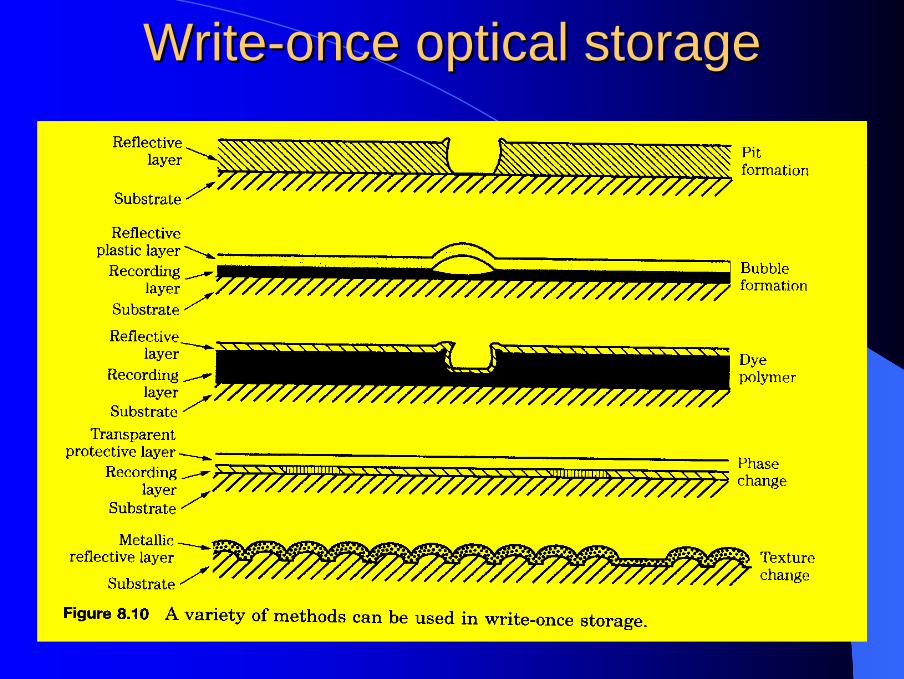
WriteWrite--once optical storageonce optical storage

MagnetoMagneto--optical recordingoptical recordingMagneto-optical recording uses a vertical magneticmedium in which magnetic particles are placed perpendicularly to the surface of a pre-grooved disc.A laser beam and magnetic bias field are used to record and erase data, and a laser beam alone is used to read data. A unique property of magnetic materials is used. As the oxide particles are heated to their Curie temperature, their coercivity decreases radically.In other words, when heated, a magnetic material loses its resistance to change in its magnetic orientation; therefore, its orientation can be affected by a small applied magnetic field.

MagnetoMagneto--optical recordingoptical recording

MagnetoMagneto--optical recordingoptical recordingIn the case of MO recording, a magnetic field is used to record data. A laser beam heats a spot of magnetic material to its Curie temperature. Only the particles in that spot are affected by the magnetic field.

MagnetoMagneto--optical readingoptical readingThe Kerr effect is used to read data; it describe the slight rotation of the plane of polarization of polarized light as it reflected from a magnetized material.

MagnetoMagneto--optical readingoptical reading
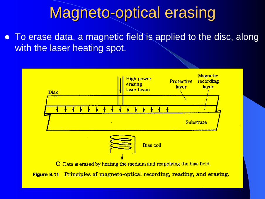
MagnetoMagneto--optical erasingoptical erasingTo erase data, a magnetic field is applied to the disc, along with the laser heating spot.

MagnetoMagneto--optical recordingoptical recordingA variety of magnetic materials can be used, selected on the basis of signal-to-noise ratio, orientation properties, and long term stability.In general, amorphous, thin-film magnetic materials are used such as terbium ferrite cobalt ( Tb-Fe-Co ).At room temperature, the coercivity of the recording layer can be more than 10000 oersteds, effectively eliminating the possibility of accidental erasure.A two-sided, preformatted, 5.25-inch constant angular velocity disc holds 650 MB of data.The MiniDisc format uses a small MO disc; it is designed to provide record-ability and portability.

MagnetoMagneto--optical recordingoptical recording

PhasePhase--change optical recordingchange optical recordingThey use materials that exhibit a reversible crystalline / amorphous phase change when recorded at one temperature and erased at another.Information is recorded by heating an area of the crystalline layer to a temperature slightly above its melting point. When the area rapidly cools and solidifies, it is amorphous.When the area is heated to a point just below its melting temperature and cooled gradually, it will return to a crystalline state.(Ga-Sb)(In-Sb), TeGeIn, GeSbTe, and AgInSbTe are used.

PhasePhase--change optical recordingchange optical recording

PhasePhase--change optical recordingchange optical recording
Initialized Active Layer Written Bit
Temp.
Tm
Tg
Write Read Erase
Time

PhasePhase--change optical recordingchange optical recording

PhasePhase--change optical recordingchange optical recording
Laser spotnew data
old data
T cryst.
T melt
P write
P erase
P read