Optical Interleavers - Optoplex Optical Interleaver Brochure Rev1.3.pdf · Optical Interleavers...
11
Optoplex Corporation, 48500 Kato Road, Fremont, CA 94538, USA. Tel: (510) 490–9930, Fax: (510) 490–9330, www.optoplex.com, [email protected] Optoplex C O R P O R A T I O N TM Optoplex C O R P O R A T I O N TM C O R P O R A T I O N TM Optical Interleavers Optoplex’s Optical Interleaver products are based on our patented Step-Phase Interferometer design. Used as a DeMux (or Mux) device, an optical interleaver separates (or combines) the Even and Odd channel signals (see the schematic diagrams in Figure 1 below). Each optical interleaver device is optimized to cover either C- or L-band wavelengths, with the option of covering C+L band. The current optical interleaver product family supports 100- 200, 50-100, 25-50 GHz, and other custom channel spacings. The DeMux and Mux interleavers can be effectively co-packaged into a single box for easy handling and cost-saving. Dual-stage optical interleavers (such as 25-100 GHz channel spacing) and asymmetric interleavers (Even and Odd channels have different passband bandwidths) are also available. Key Features and Benefits Wide and flat passband Minimal PDL High channel isolation Minimal thermal drift Low and customizable dispersion Low insertion loss & IL uniformity Dual C- and L-band coverage DeMux/Mux co-packaged solution available Asymmetric/uneven optical interleaver available Telcordia GR-1221/63 qualified Applications Extend existing network capacity Bridge existing & new DWDM platforms System upgrade Bi-directional networks Total signal power detection for Raman amplifier Multi-wavelength transponder Flat-top comb filter … … … Input Output Odd Even … … Input … Output Odd Even Optical De-Interleaver Optical Interleaver … … … Input Output Odd Even … … … Input Output Odd Even … … … Input … Output Odd Even Optical De-Interleaver Optical Interleaver Figure 1 - Schematic diagrams of optical de-interleaver and interleaver. -35 -30 -25 -20 -15 -10 -5 0 1563 1564 1565 1566 1567 1568 Wavelength (nm) Insertion Loss (dB) Figure 2 - Measured Spectral Profiles of a 100/200GHz interleaver.
Transcript of Optical Interleavers - Optoplex Optical Interleaver Brochure Rev1.3.pdf · Optical Interleavers...

Optoplex Corporation, 48500 Kato Road, Fremont, CA 94538, USA. Tel: (510) 490–9930, Fax: (510) 490–9330, www.optoplex.com, [email protected] Optoplex
C O R P O R A T I O N
TMOptoplexC O R P O R A T I O N
TM
C O R P O R A T I O N
TM
Optical Interleavers Optoplex’s Optical Interleaver products are based on our patented Step-Phase Interferometer design. Used as a DeMux (or Mux) device, an optical interleaver separates (or combines) the Even and Odd channel signals (see the schematic diagrams in Figure 1 below). Each optical interleaver device is optimized to cover either C- or L-band wavelengths, with the option of covering C+L band. The current optical interleaver product family supports 100-200, 50-100, 25-50 GHz, and other custom channel spacings. The DeMux and Mux interleavers can be effectively co-packaged into a single box for easy handling and cost-saving. Dual-stage optical interleavers (such as 25-100 GHz channel spacing) and asymmetric interleavers (Even and Odd channels have different passband bandwidths) are also available.
Key Features and Benefits
Wide and flat passband Minimal PDL High channel isolation Minimal thermal drift Low and customizable dispersion Low insertion loss & IL uniformity Dual C- and L-band coverage DeMux/Mux co-packaged solution
available Asymmetric/uneven optical interleaver
available Telcordia GR-1221/63 qualified
Applications
Extend existing network capacity Bridge existing & new DWDM platforms System upgrade Bi-directional networks Total signal power detection for Raman
amplifier Multi-wavelength transponder Flat-top comb filter
………
Input Output
Odd
Even
……
Input
…Output
Odd
Even
Optical De-Interleaver
Optical Interleaver
………
Input Output
Odd
Even
………
Input Output
Odd
Even
………
Input
…Output
Odd
Even
Optical De-Interleaver
Optical Interleaver
Figure 1 - Schematic diagrams of optical de-interleaver and interleaver.
-35
-30
-25
-20
-15
-10
-5
0
1563 1564 1565 1566 1567 1568
Wavelength (nm)
Inse
rtion
Los
s (d
B)
Figure 2 - Measured Spectral Profiles of a 100/200GHz interleaver.
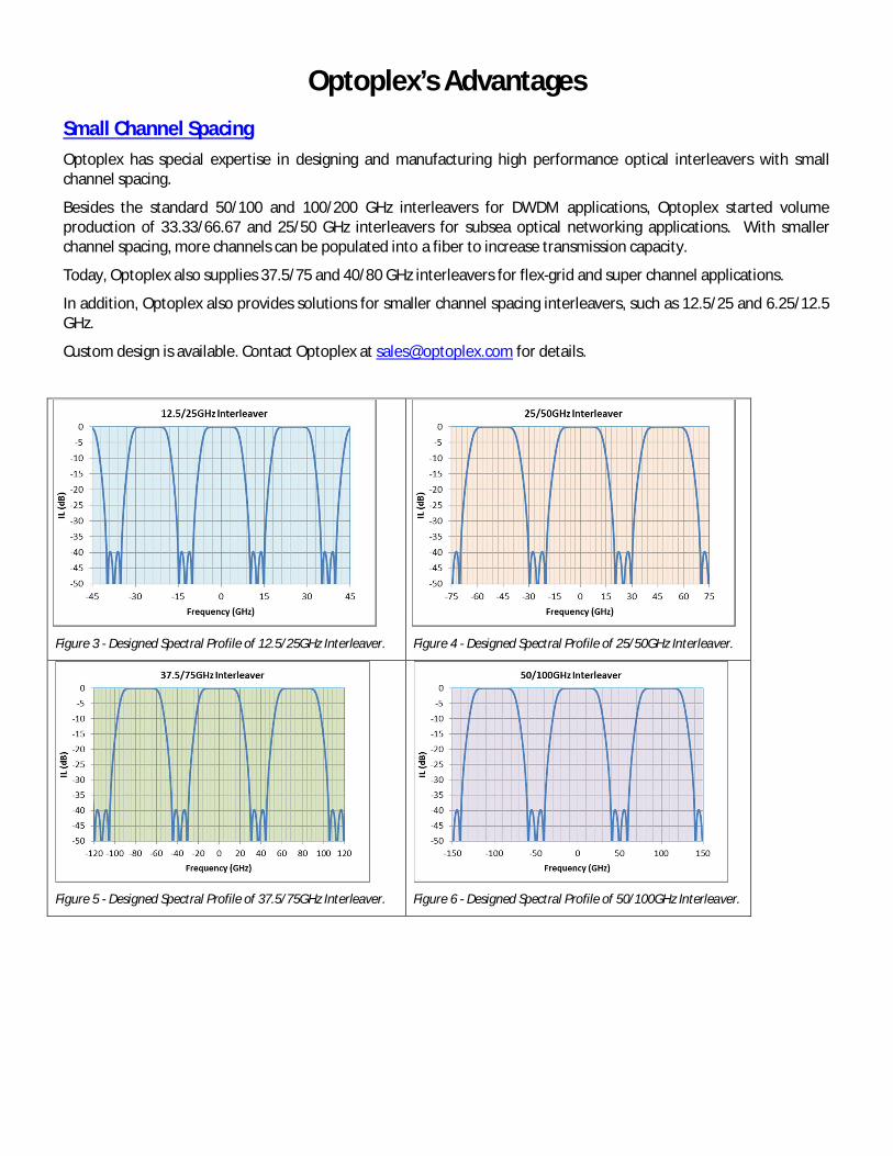
Optoplex’s Advantages Small Channel Spacing Optoplex has special expertise in designing and manufacturing high performance optical interleavers with small channel spacing.
Besides the standard 50/100 and 100/200 GHz interleavers for DWDM applications, Optoplex started volume production of 33.33/66.67 and 25/50 GHz interleavers for subsea optical networking applications. With smaller channel spacing, more channels can be populated into a fiber to increase transmission capacity.
Today, Optoplex also supplies 37.5/75 and 40/80 GHz interleavers for flex-grid and super channel applications.
In addition, Optoplex also provides solutions for smaller channel spacing interleavers, such as 12.5/25 and 6.25/12.5 GHz.
Custom design is available. Contact Optoplex at [email protected] for details.
Figure 3 - Designed Spectral Profile of 12.5/25GHz Interleaver. Figure 4 - Designed Spectral Profile of 25/50GHz Interleaver.
Figure 5 - Designed Spectral Profile of 37.5/75GHz Interleaver.
Figure 6 - Designed Spectral Profile of 50/100GHz Interleaver.

Asymmetric Design Usually, an optical interleaver offers symmetric optical spectral profiles for both odd- and even- output ports (except for the frequency off-set applied on one port with respect to the other).
Optoplex is able to design “asymmetric interleaver” from which the odd and even output spectra is asymmetric, for instance, 70% bandwidth for the odd channel and 30% for the even channel. The ratio can be custom designed to satisfy your demanding applications.
Normally, the signal spectral profiles (bandwidths) are different for signals of different data rates. For instance, 100Gbps signal’s spectrum is wider than 40Gbps’, and 40Gbps’ is wider than 10Gbps'.
With Optoplex’s Asymmetric Interleavers, one can easily Mux different data rates' signals together, or oppositely DeMux different data rates' signals.
Asymmetric interleaver can be made for any channel spacing.
Figure 8 - Symmetric Interleaver Illustration. Figure 9 - Measured output spectra of a symmetric 50/100GHz interleaver.
Figure 10 - Asymmetric Interleaver Illustration. Figure 11 - Measured output spectra of an asymmetric interleaver.
Asymmetric Interleaver Symmetric Interleaver
Figure 7 - Stand-alone Standard and Asymmetric Interleavers.

Super-Wide Passband Interleaver By nature, Optoplex’s optical interleaver has much wider bandwidth than the same of interleavers built by other technologies. For instance, the 0.5dB bandwidth of Optoplex’s standard 50/100GHz interleaver is about 30GHz (CCF +/-15GHz, CCF = channel center frequency), while, the 3dB BW of interleavers built by other technologies is about 20GHz (CCF+/-10GHz).
On top of that, Optoplex has developed and launched a “super”-wide passband interleaver (called “super interleaver”) that offers even wider bandwidth. For example, the 3dB bandwidth of 50/100GHz “super” interleaver is larger than 40GHz. Moreover, the “super” interleaver offers much wider stop-band bandwidth, more than 35GHz (at -25dB), comparing to about 20GHz by competitive technologies’.
Optoplex’s super interleaver is an ideal optical component in 100Gbps and 400Gbps applications. It improves the spectral power efficiency and OSNR performance in super-channel and high data rate transmission where the signal spectrum is wider.
The “super”-wide passband interleaver can be applied to the design of any channel spacing optical interleaver, from 12.5GHz to 200GHz. Contact Optoplex at [email protected] for more details.
Figure 12 - “Super”-Wide Passband Interleaver. Figure 13 - Standard Interleaver.
Figure 14 - 0.5dB BW of “Super”-Wide Passband Interleaver. Figure 15 - 0.5dB BW of Standard Interleaver.

Figure 16 - Stop-Band of “Super”-Wide Passband Interleaver. Figure 17 - Stop-Band of Standard Interleaver.
Low-Chromatic Dispersion Design Normally, the chromatic dispersion in the pass-band (@-0.5dB) of a 50/100GHz interleaver is about +/-200ps/nm (max). Optoplex developed a special design for low chromatic dispersion that is about +/-15ps/nm in a 50/100GHz interleaver. See below charts. Low chromatic dispersion is very important in high-speed long-haul transmission, especially in those non-coherent systems.
Low-CD design can be applied to any channel spacing interleaver, from 12.5/25GHz to 200/400GHz. Contact Optoplex at [email protected] for more details.
Low-CD Interleaver Standard Interleaver
Figure 18 - Low-CD Interleaver. Figure 19 - Standard Interleaver.

Figure 18 - 0.5dB BW of Low-CD Interleaver. Figure 19 - 0.5dB BW of Standard Interleaver.
Figure 20 - Stop-Band of Low-CD Interleaver. Figure 21 - Stop-Band of Standard Interleaver.
Low-CD Interleaver Standard Interleaver
Figure 22 - CD Spectrum of Low-CD Interleaver. Figure 23 - CD Spectrum of Standard Interleaver.

Figure 24 - Zoom-in CD Spectrum of Low-CD Interleaver. Figure 25 - Zoom-in CD Spectrum of Standard Interleaver.
Co-Packaged Solution Optoplex has proprietary technology to design and manufacture “co-packaged” interleaver – that is a Mux and a DeMux interleavers share the same optics in a package with the same form factor as used in an individual interleaver. Compare to discrete (using two individual interleavers, one as a Mux and another one as a DeMux) approach, Optoplex’s Co-Packaged solution offers below:
Features & Benefits
Save 50% space (compared to that of individual solution where a separate Mux and DeMux are used) At least 30% of cost-saving than the individual solution Same performance (as individual approach) Same reliability (as individual approach) Proven track records
Single-Stage Co-Packaged Solution
Figure 26 - Interleaver DeMux. Figure 27 - Interleaver Mux. Figure 28 - Co-Packaged Interleaver (Mux/DeMux).

Two-Stage Co-Packaged Solution
Figure 29 - A standard two-stage 50/200GHz Interleaver. Figure 30 - A Mux/DeMux Co-Packaged 50/200GHz Interleaver.
Figure 31 - 25/50GHz Mux/DeMux Co-Packaged Interleaver Module.
Figure 32 - 50/100GHz Mux/DeMux Co-Packaged Interleaver Module.
Figure 33 - 50/200GHz Two-Stage Mux/DeMux Co-Packaged Interleaver Module.
Multiple-Staged Interleaver Multiple-stage interleaver solutions are available. The configurations include:
Two-Stages:
o 25/100GHz
o 33.3/133.34GHz
o 50/200GHz
o 100/400GHz
o Other customer specific
Three-Stages:
o 25/200GHz
o 37.5/300GHz
o 50/400GHz
o Other customer specific
Options
o Mux/DeMux co-packaged solution o “Super”-wide passband design o Low-CD design
Contact Optoplex at [email protected] for details.
25/50GHz 50/100GHz
50/200GHz

Switchable Interleaver Optoplex developed a special interleaver, called “hitless switchable interleaver”. It operates in two modes: At Mode-1, all input signals (from Port-A) go through directly to Port-B (all channels); At Mode-2, it functions like a regular interleaver – even channels output at Port-B while odd channels output at Port-C. During the change of operation mode, there is no hit to the output – it is “hitless”.
The hitless switchable interleaver can be designed for any channel spacing from 12.5/25GHz to 200/400GHz.
If you have any special requirement for such switchable interleaver, please contact Optoplex at [email protected].
During mode switching, Even-Channels (Port-B) are not affected Hitless!
Figure 34 - Schematic Diagram and Functionality of Switchable Hitless Interleaver.
Custom Design
Spectral Profile
Optoplex has expertise in designing and manufacturing customer-specific interleavers to satisfy your demanding applications. Besides the channel spacing (or FSR), we can tailor the design to achieve special optical performance such as bandwidth, isolation, and chromatic dispersion, etc. Of course, the asymmetric interleaver is also available.
Functionalities
Co-packaged design is to have both Mux and DeMux functions equipped in a package with a form factor the same as an individual interleaver (only functions as a Mux or a DeMux).
Multiple-stage configuration is available. Again, co-packaged solution can be applied to multi-stage interleaver to save dramatic space and the cost.
Integration
Optoplex can also integrate other optical components with optical interleavers, such as optical couplers/splitters, Taps and Photo-didoes, OSC filter, Red/Blue filters, and/or other DWDM filters.
In a complex system, such as multiple-stage interleavers integrated with couplers, PDs and filters, Optoplex’s co-packaged solution has benefits over other competitive technologies’ since it takes much less space and it is much cost-effective.
Contact Optoplex at [email protected] for the best solution to satisfy your needs.
Mode 2: Interleaver mode Port-A: All channels Port-B: Even channels Port-C: Odd channels
Mode 1: All-pass mode Port-A: All channels Port-B: All channels Port-C: No light

Optoplex Corporation, 48500 Kato Road, Fremont, CA 94538, USA. Tel: (510) 490–9930, Fax: (510) 490–9330, www.optoplex.com, [email protected] Optoplex
C O R P O R A T I O N
TMOptoplexC O R P O R A T I O N
TM
C O R P O R A T I O N
TM
Product Specification: Standard Interleaver (C-, L-, or C+L band, Bi-directional, Regular-design (except Low CD)), R1.1; 8-19-16
50-100 GHz 50-100 GHzLow CD High CD
Wavelength Range nmChannel Center Alignmemt -
Insertion Loss1 (without connector)
dB <2.6
Insertion Loss Uniformity1
(over all channels)dB
Passband Width1 @0.5dB GHz >ITU±7 >ITU±9 >ITU±11 >ITU±15 >ITU±15 >ITU±30 >ITU±50
>20 over >21 over >22 over >24 over >24 over >24 over >24 overITU±5 GHz ITU±7 GHz ITU±7.5 GHz ITU±8 GHz ITU±8 GHz ITU±16 GHz ITU±30 GHz
Passband Ripple1 (within 0.5dB passband)
dB <0.5 <0.4
PDL1 (within 0.5dB passband) dB<±320 over <±200 over <±140 over <±35 over <±75 over <±20 over <±10 overITU±5 GHz ITU±7 GHz ITU±7.5 GHz ITU±10 GHz ITU±10 GHz ITU±16 GHz ITU±30 GHz
PMD1 (within 0.5dB passband)
psReturn Loss dB
Directory dBMax Input Power mW
Operating Temperature ˚CStorage Temperature ˚C
Dimension (L x W x H) mmPigtail Type -
Connector Type -Pigtail Length m
Chromatic Dispersion1 ps/nm
<1.8
<0.4
<0.2
<0.2<0.3
<0.5
Parameter 25-50 GHz 33.33-66.67 GHz 100-200 GHz37.5-75 GHz
<0.3
Channel Isolation1
0 ~ 65
<2
>45>40
200-400 GHzUnit
300
dB
1527 ~ 1567 for C-band, 1567 ~ 1607 for L-band, or 1527 ~ 1607 for C+L band ITU Grid
<0.2
1.0±0.1FC, LC, SC, MU, or no Connector
SMF-28 or equipvalent with 900µm tight buffer122 x 70 x 14
- 40 ~ 85
1. Over the stated spectral and operating temperature ranges and all polarization states.

Ordering Information Part Number Assignment for Standard Interleavers (Examples below are for C-band, Regular design (except Low CD), and FC/UPC connector.) See below for P/N rules. Contact Optoplex should you have any question or what you need are not among below list.
Channel Center Frequency (CCF) Alignment on ITU Grid with ITU+50GHz with ITU+25GHz with ITU-25GHz with ITU+12.5GHz
25-50 GHz IL-C0RBFCS002 NA NA NA IL-C0RBFCS004 33.33-66.67 GHz IL-CTRBFCS002 NA NA NA NA 37.5-75 GHz IL-CBRBFCS001 NA NA NA IL-CBRBFCS002 50-100 GHz Low CD IL-C1LBFCS001 NA IL-C1LBFCS005 NA IL-C1LBFCS010 50-100 GHz High CD IL-C1RBFCS002 NA IL-C1RBFCS007 NA IL-C1RBFCS012 100-200 GHz IL-C2RBFCS001 IL-C2RBFCS002 IL-C2RBFCS005 IL-C2RBFCS006 IL-C2RBFCS009 200-400 GHz (Even) IL-C3RBFCS001 IL-C3RBFCS005 IL-C3RBFCS009 IL-C3RBFCS011 IL-C3RBFCS017 200-400 GHz (Odd) IL-C3RBFCS003 IL-C3RBFCS007 IL-C3RBFCS013 IL-C3RBFCS015 IL-C3RBFCS018
Interleaver P/N Rules
Specification C = Custom S = Standard
Package Type C = Compact B = Box
Channel Spacing 0 = 25-50 GHz 1 = 50-100 GHz 2 = 100-200 GHz 3 = 200-400 GHz A = 12.5-25 GHz B = 37.5-75 GHz D = 6.25-12.5 GHz E = 20-40 GHz T = 33.3-66.7 GHz F = 40-80 GHz G = 66.7-133.3GHz
Band C = C-Band L = L-Band T = C+L Band
Sequential Number Starts from 001
Connector Type FC = FC/UPC FA = FC/APC LC = LC/UPC SC = SC/UPC MU = MU/UPC XX = No connector
Design Type S = Super R = Regular L = Low CD
IL -


![Blind Estimation of Block Interleaver Parameters using ...€¦ · every interleaving period. These characteristics are used as clues of estimating interleaving periods [3], [4].](https://static.fdocuments.us/doc/165x107/5f4437d4adc37e673a09b0c7/blind-estimation-of-block-interleaver-parameters-using-every-interleaving-period.jpg)