
OPTICAL DISTRIBUTION FRAMES...MFDC ORDERING CODE The MFDC Cabinets o˜er termination and splicing...
28
WWW.OPTOKON.COM OPTICAL DISTRIBUTION FRAMES High quality cable management system OPTOKON CABLE MANAGEMENT - 10 YEAR WARRANTY ... managing optical cables with OPTOKON is EASY!
Transcript of OPTICAL DISTRIBUTION FRAMES...MFDC ORDERING CODE The MFDC Cabinets o˜er termination and splicing...

WWW.OPTOKON.COM
OPTICAL DISTRIBUTION FRAMESHigh quality cable management system
OPTOKON CABLE MANAGEMENT - 10 YEAR WARRANTY
... managing optical cables with OPTOKON is EASY!

STANDARD / INSTALLATIONOPTOKON manufactures comprehensive �ber optic cable management systems delivering high performance solutions for passive network installations. OPTOKON systems meet today’s requirements for tomorrow’s applications. These advanced modular �ber optic systems include the full range of passive components for singlemode and multimode applications that when combined, provide complete solutions for today’s applications, and maximize physical infrastructure performance, reliability, modularity and scalability.
Central O�ce
Distribution Node (POP)
End User (CPE)
ABOUT OPTOKON
RACK MOUNT OFDU-S Splice cabinetOFDU-T Termination cabinetODFU-TS Splice and termination cabinetMFDC Splice and termination cabinetMCNP Connector network panelZMPJ Fixed cabinetTMVJ Cabinet with slide-out shelfECNP ETSI Connector Network Panel
WALL MOUNTMPIC Interconnect cabinetMSIC Splice cabinetFO 22 Splice and termination boxMCPE End user termination box
OUTDOORMOPF Fiber optic termination boxMOMB Outdoor metal �ber optic box, IP66
19” RACKS MROM The complete FTTH solutioniSEVEN 600 and 800 mm wide 19" racksREN Wall mount rack
ACCESSORIESCNPM Coupling panelsCAPM CassettesFP Front panelSplice Trays
CABLE CLOSURESFiber optic splice closures
Content
ZMPJ
ODFU-S
ODFU-TS
ZMVJ
FO 22 MOPF
MCPE
CAPM
MOMB

OUR PRODUCTION
OPTOKON CABLE MANAGEMENT 10 YEAR WARRANTY
GENERAL INFORMATION
The OPTOKON standard 10 year warranty is valid for all cable management components from the OPTOKON range manufactured from ALUMINIUM. This includes all racks, cabinets, shelves, connector panels. The warranty does not extend to any cables, connectors, adaptors, pigtails or any other component �tted into the cable management system as an accessory. This warranty is valid and e�ective from 1/5/2006 and is not applicable to any aforementioned product purchased from OPTOKON prior to this date. Any OPTOKON cable management product purchased prior to 1/5/2006 is governed by the standard OPTOKON one year warranty valid at the date of purchase.
Terms and conditions for the standard ten year warranty are available at WWW.OPTOKON.COM or by request from [email protected]
ETSIThis European Telecommunication Standard (ETS) has been produced by the Equipment Engineering (EE) Technical Committee of the European Telecommunications Standards Institute (ETSI). The European Telecommunication Standard is aimed at setting out, on a common basis, the engineering requirements for telecommunication practice, for housing equipment forming part of a public telecommunications network. This ETS applies to all telecommunications equipment forming part of the public telecommunications network.
IEC 60297Apart from the ETSI range, all cabinets in this catalogue generally conform to IEC 60297 and AS 1939 standards for 19” racking. This standard forms the basis of all other related 19" standards. Strict conformance to the details of the mounting of 19" equipment is essential for the racks, subracks and internal housings. However strict conformance relating to external cabinet dimensions imposes severe design styling constraints for relatively minor bene�ts. Where close conformance is demanded we suggest our 2005 range.
1 RU = 44.45 (1 3/4")
For tolerance requirements reduce calculated height by 0.8 mm.
e.g. 3 RU3 x 44.45= 133.35 – 0.8 = 132.55
Therefore, 132.55 is the actual height.
482.6mm
482.6mm465mm
12.7m
m15
.88m
m31
.75m
m
31.75
mm
6.35m
m
8.8mm
44.45
mm
(1RU
)44
.45m
m (1
RU)
multiples of rack units
panels must meet at mid-point between
rack units
535mm
535mm515mm
25m
m (1
SU)
12.5m
m
10mm
25m
m (1
SU)
25m
m
multiples of rack units
panels must meet at mid-point between mounting
centres

RACK MOUNT - Rack Mount Splice Cabinet
OFDU-S
ORDERING CODE
The OFDU-S cabinet is based on universal optical distribution frames. The uni�ed modular system enables easy recon�guration and can be extended according to operator requirements. The OFDU-S provides splicing, storage and protection of up to 288 �ber splices in individually accessible trays. The slide-out and swing down shelf enables unrestricted front, rear and top access to the splicing area. Various types of splice trays can be used.
FEATURES
Splicing of up 288 �bers in one cabinetFixed or hinged cassette installationSlide-out and drop down shelfAluminum material - low weight and shipment costsBend radius protection protection enables management and rearrangement of cable slackRemovable top provides unrestricted access to splice tray and �ber connectionsCable strain-relief hardware providedDurable powder coat �nish – RAL 9006
Parts available separately:
1 OFDU-BU-X base unit5 OFDU-SS sliding shelf6 OFDU-RC-X rear cover7-10 OFDU-CH-X cassette holder11 OFDU-TC top cover12 OFDU-DM-X front door metal (plexi)13 Key lock / latch14 UH-X unit holder15 BRP reel
TECHNICAL SPECIFICATIONS
Note:V1 – variant: contains one cassette holder and one pair of BRP reelsV2 – variant: contains two cassette holders and two pairs of BRP reels
Note: 1) Splice Tray: CMS_01-09_EN-KNS Splice_trays 2) OFDU-S2: max. 12 splice cassettes: one holder for 6 or two holders for 12 splice cassettes OFDU-S3: max. 24 splice cassettes: one holder for 12 or two holders for 24 splice cassettes
Key lock
Metal latch 109
7
1
12
6
5
11
13
14
15
431,5
130
291
PART NUMBER FIBER CAPACITY RACK
UNITS DIMENSIONS (HxWxD) mm
SHIP WGT (kg) EQUIPMENT CAPACITY
OFDU-S2-V1 6 splice cassettes 72 2U 88 x 432 x 305 1.4
OFDU-S2-V2 2 x 6 splice cassettes 144
OFDU-S3-V1 12 splice cassettes 144 3U 133 x 432 x 305 1.9
OFDU-S3-V2 2x 12 splice cassettes 288
OFDU-SX - VX - XX - XX
Version, rack units Front door option OFDU-S2 2U LM Metal door-lock OFDU-S3 3U ZM Metal door-latch
LP Plexi door - lock ZP Plexi door - latch
Variant, number of holders Number of splice cassettes V1 – 1x cassette holder, 1x BRP 01-24 Number of cassettes V2 – 2x cassette holder, 2x BRP
Hinged cassette installation

RACK MOUNT - Termination Cabinet
OFDU-T
ORDERING CODE
The OFDU-T cabinet is based on universal optical distribution frames. The uni�ed modular system enables easy recon�guration and can be extended according to operator needs. The OFDU-T provides termination in convenient housing unit. The OFDU-T terminates up to 144 �bers in a 3U distribution frame. This unit can take up to 12 snap-in coupling panels or prewired cassettes. The slide-out and swing down shelf enables unrestricted front, rear and top access to termination panels and cable reserve.
FEATURES
Termination cabinetSlide-out and drop down shelfAluminum material - low weight and shipment costsUp to 144 - �ber terminationRemovable top and back cover enables unrestricted front, rear and top accessFor FTTH use - microtube holder includedPrewired CAPM cassettes include connectorized �ber pigtails and adaptersLockable or latch door options are available Durable powder coat �nish - RAL 9006
Parts which are available separately:
1 OFDU-BU-X base unit5 OFDU-SS sliding shelf6 OFDU-RC-X rear cover7 OFDU-CP-X connector panel12 OFDU-TC top cover13 OFDU-DM-X front door metal (plexi)14 Key lock / latch15 UH-X unit holder16 BRP reel radius protection
X=2,3 – rack unit
TECHNICAL SPECIFICATIONS
PART NUMBER RACK UNITS DIMENSIONS (H x W x D) mm SHIP WGT (kg)
OFDU-T2 2U 88 x 432 x 305 1.5 OFDU-T3 3U 133 x 432 x 305 1.9
Note: 1) CNPM coupling panel: CMS_24-01_EN-CNPM CAPM prewired cassette with pigtails and adapters: CMS_22-01_EN-CAPM
Key lock
Metal latch
1
13
5
12
14
15
7
6
16
130
431,5
295
OFDU-T2 - typical patch panel capacity
CNPM or CAPM1 Max Fibers CNPM-XX-06
6 36
CNPM-XX-08 48 CNPM-XX-12 72
OFDU-T3 - typical patch panel capacity CNPM-XX-06
12 72
CNPM-XX-08 96 CNPM-XX-12 144
OFDU-TX - XXX - XX X - XX
Version Front Door Option OFDU-T2 2U LM Metal door - lock OFDU-T3 3U ZM Metal door - latch
LP Plexi door - lock ZP Plexi door - latch
Panel Capacity Coupling Type Application 006 – 144 Fibers ST ST adapter M Multimode
SC SC adapter S Singlemode FC FC adapter A APC E2 E2000 adapter x No adapters DSC SC duplex adapter DLC LC duplex adapter DMU MU duplex adapter MJ MT-RJ adapter

RACK MOUNT - Rack Mount Splice and Termination Cabinet
OFDU-TS
ORDERING CODE
The OFDU-TS cabinet is based on universal optical distribution frames. The uni�ed modular system enables easy recon�guration and can be extended according to operator needs. The OFDU-TS provides splicing and termination within one convenient housing unit. The OFDU-TS terminates up to 144 �bers in a 3U distribution frame. This unit can take up to 12 snap-in coupling panels or prewired cassettes. The slide-out and swing down shelf enables unrestricted front, rear and top access to the splicing area and termination panels. Various types of splice trays can be used.
FEATURES
Splicing and termination in one cabinetSlide-out and drop down shelfAluminum material - low weight and shipment costsUp to 144 - �ber terminationSplicing in single splice trays, individual splice tray access Fixed or hinged cassette installationRemovable top and back cover enables unrestricted front, rear and top accessFor FTTH use - microtube holder includedLockable or latch door options are available Durable powder coat �nish - RAL 9006
Parts available separately:
1 OFDU-BU-X base unit5 OFDU-SS sliding shelf6 OFDU-RC-X rear cover7 OFDU-CP-X connector panel8-11 OFDU-CH-X cassette holder12 OFDU-TC top cover13 OFDU-DM-X front door metal (plexi)14 Key lock / latch15 UH-X unit holder
X=2,3 – rack unit
TECHNICAL SPECIFICATIONS
Note: 1) Splice Tray: CMS_01-09_EN-KNS Splice_trays 2)CNPM coupling panel: CMS_24-01_EN-CNPM CAPM prewired cassette with pigtails and adapters: CMS_22-01_EN-CAPM
PART NUMBER RACK UNITS DIMENSIONS (H x W x D) mm SHIP WGT (kg)
OFDU-TS2 2U 88 x 432 x 305 1.5 OFDU-TS3 3U 133 x 432 x 305 1.9
OFDU-TS2 - typical �ber capacity Splice Tray1 Max Fibers CNPM or CAPM2 Max Fibers
KNS-12 6 72 CNPM-XX-06 6
36 CNPM-XX-08 48 CNPM-XX-12 72
OFDU-TS3 - typical �ber capacity KNS-12 12 144 CNPM-XX-06
12 72
CNPM-XX-08 96 CNPM-XX-12 144
Key lock
Metal latch
OFDU-TSX - X - XXX - XX X - XX
Version Front Door Option OFDU-TS2 2U LM Metal door - lock OFDU-TS3 3U ZM Metal door - latch LP Plexi door - lock Number of Splice Trays ZP Plexi door - latch
1-12 Number of Splice Trays Coupling Type Applications
ST ST adapter M Multimode SC SC adapter S Singlemode FC FC adapter A APC Fiber Capacity E2 E2000 adapter x No adapters 006 – 144 Fibers DSC SC duplex adapter DLC LC duplex adapter
DMU MU duplex adapter MJ MT-RJ adapter
Hinged cassette installation
1110
8
1
7
13
6
12
14
15
5
16
130
431,5
295

RACK MOUNT - Splice and Termination Cabinet
MFDC
ORDERING CODE
The MFDC Cabinets o�er termination and splicing within one convenient housing. The MFDC terminates up to 144 �bers in a 6U frame. This unit accepts 12 snap-in coupling panels or prewired cassettes. Fibers are routed to the lower section of the unit where splice trays, �ber bundles, and bu�er tubes are stored. Various types of splice trays, blocks of 12 splice cassettes can be located on a pullout shelf, allowing easy access to the bu�er tube, �ber storage and splicing area. MFDC-T is special variant which contains only 24 snap-in coupling panels for high density termination. It accommodates of up to 288 optical adapters.
FEATURES
Aluminium material providing low weight and shipping costsAccommodates up to 144 �ber splices or 288 optical adapters Splicing in single splice trays or in block of 12 cassettes Individual splice tray access Removable top and back cover allows unrestricted front, rear and top accessPrewired CAPM cassettes include connectorized �ber pigtails and adaptersKey lock and metal latch door options are available Durable powder coat �nishLabels provided to document splice and termination locations
TECHNICAL SPECIFICATIONS
Note: 1) see datasheet CMS_21-01_EN-Splice trays 2) MFDC-T without splicing cassettes and sliding shelf serves only for termination using up to 288 optical adapters
MFDC - (T) - X - XXX - XX X - XX
Version Front Door Option
MFDC Standard 12x panels,
LM Metal door-lock
sliding shelf, cassettes ZM Metal door-latch
MFDC-T Special 24x panels, no sliding shelf, no cassettes Applications
M Multimode Number of Splice Trays S Singlemode 0-12 Number of splice trays A APC applications BC12 Block of 12 splice trays NC No cassettes Coupling Type
ST ST adapter Fiber Capacity SC SC adapter 000 – 144 Fibers FC FC adapter
E2 E2000 adapter DSC SC duplex adapter DLC LC duplex adapter MU MU adapter MJ MT-RJ adapter
PART NUMBER RACK UNIT
DIMENSIONS (H x W x D) mm
SHIP WGT (kg)
Purpose
MFDC 6U 267 x 432 x 305 2.9
Splice & termination
MFDC-T Termination only
267
432305
EQUIPMENT PARAMETERS Cassette type Number of cassettes Splicing capacity
Cassettes KNS-12S1 12 144 Block of cassettes TC-248S1 1 144
No splicing cassettes2 0 0
Patch panel type Number of patch
panels Termination capacity
CNPM-XX-06 12
72 CNPM-XX-08 96 CNPM-XX-12 144 CNPM-XX-06
242 144
CNPM-XX-08 192 CNPM-XX-12 288

RACK MOUNT - Rack Mount Connector Network Panel
MCNP
ORDERING CODE
The MCNP Connector Network Panel is an economical rack mountable patch panel for use with splicing of manufactured pigtails, preterminated cables and �eld-installable connectors. The cables are strain-relieved at the rear of the unit. The pivoting shelf can be equipped with either a splice tray holder or bend radius protection which guides, stores and organizes excess slack. This prevents damage to �bers prior to routing into couplings. The MCNP is used in installations where space is limited.
FEATURES
Splicing and termination optical cable in one boxAluminum material - low weight and shipment costsExtended (3 coupling panels per 1U) version availableSplice cassette holder enables cable termination with the help of pigtail splicingAccommodates up to 24 �bers in 1 rack unitRemovable top cover provides unrestricted accessPivoting shelf eases connector routing and cable routingCable strain-relief and grounding provisionsAccepts industry standard connector typesFTTH use – microtubes holder includedPassed seismic tests according to ASME standards Approved for construction of nuclear power plant components
TECHNICAL SPECIFICATIONS
Note: 1) Splice Tray: CMS_01-09_EN-KNS Splice_trays CNPM coupling panel: CMS_24-01_EN-CNPM CNPM-XX-06 6 pcs ST, FC, SC, E2000, ... adapters CNPM-XX-08 8 pcs ST, FC, SC, E2000, ... adapters CNPM-XX-12 12 pcs SC, E2000 adaptersCAPM prewired cassette with pigtails and adapters: CMS_22-01_EN-CAPM
PART NUMBER
FIBER CAPACITY1 RACK UNITS
DIMENSIONS (HxWxD) mm
SHIP WGT (kg) CNPM-XX-06 CNPM-XX-08 CNPM-XX-12
MCNP – 1S 12 16 24 1 44 x 432 x 280 2.4 MCNP – 2S 24 32 48 2 88 x 432 x 280 3.8 MCNP – 3S 36 48 72 3 133 x 432 x 280 5.2 MCNP – 1E 18 24 36 1 44 x 432 x 280 2.4 MCNP – 2E 36 48 72 2 88 x 432 x 280 3.8 MCNP – 3V 72 96 144 3 133 x 432 x 280 5.5
Parts available separately:
1 MCNP-BU-X base unit6 MCNP-TS-1 twisting shelf7 MCNP-CP-1 front panel8 MCNP-TC top cover9 Pin FH-M5-3810 Pin FH-M3-3011 UH-1_var112 Screw CNMP
X=2,3 – rack unit
MCNP 2U unit
1
7
8
611
12
10 9
43
431
273
MCNP - XX - XX - XX X - X XX
Rack Unit Type X - Option for Fiber Termination 1 1U S Standard (2 panels per 1U) B Bend radius protectors 2 2U V V Vertical (12 panels per 3U) C Splice cassette for 12 splicing 3 3U E Extended (3 panels per 1U)
XX - Number of Splice Cassettes Fiber Capacity 0 No cassette
12, 24, ..�bers (Bend radius protectors) 1 1 Splice cassette Coupling Type 2 2 Splice cassettes XX X 3 3 Splice cassettes ST ST M Multimode ... up to 12 splice cassettes SC SC S Singlemode FC FC A APC E2 LSH (E2000) MJ MT-RJ DSC duplex SC DLC duplex LC DMU duplex MU
RACK MOUNT - Enclosed Cabinet
ZMPJ
ORDERING CODE
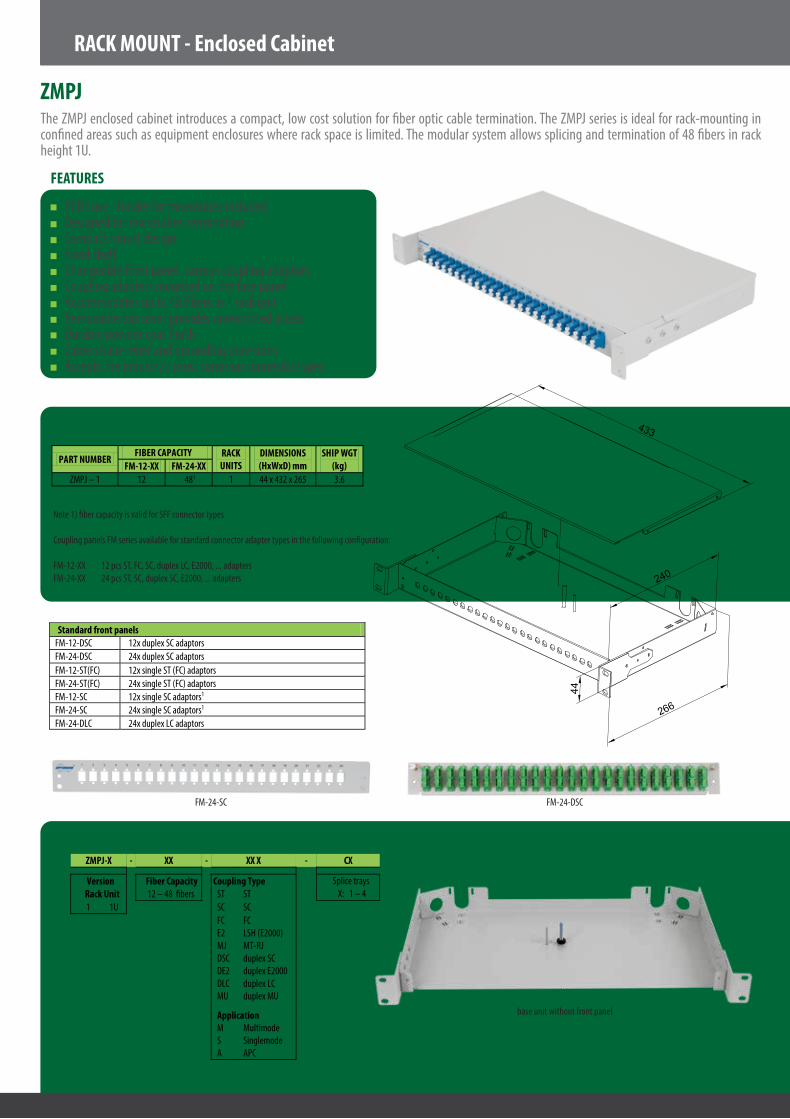
The ZMPJ enclosed cabinet introduces a compact, low cost solution for �ber optic cable termination. The ZMPJ series is ideal for rack-mounting in con�ned areas such as equipment enclosures where rack space is limited. The modular system allows splicing and termination of 48 �bers in rack height 1U.
FEATURES
FTTH use - holder for microtubes includedDesigned for microtubes terminationCompact robust designFixed shelfChangeable front panel, various coupling adaptorsCoupling adapters mounted on the face panelAccommodates up to 48 �bers in 1 rack unitRemovable top cover provides unrestricted accessDurable powder coat �nishCable strain-relief and grounding provisionsAccepts the industry's most common connector types
TECHNICAL SPECIFICATIONS
Note 1) �ber capacity is valid for SFF connector types
Coupling panels FM series available for standard connector adapter types in the following con�guration: FM-12-XX 12 pcs ST, FC, SC, duplex LC, E2000, ... adaptersFM-24-XX 24 pcs ST, SC, duplex SC, E2000, ... adapters
PART NUMBER FIBER CAPACITY RACK
UNITS DIMENSIONS (HxWxD) mm
SHIP WGT (kg) FM-12-XX FM-24-XX
ZMPJ – 1 12 481 1 44 x 432 x 265 3.6
ZMPJ-X - XX - XX X - CX
Version Fiber Capacity Coupling Type Splice trays Rack Unit 12 – 48 �bers ST ST X: 1 – 4 1 1U SC SC
FC FC E2 LSH (E2000) MJ MT-RJ DSC duplex SC DE2 duplex E2000 DLC duplex LC MU duplex MU
Application M Multimode S Singlemode A APC
Standard front panels FM-12-DSC 12x duplex SC adaptors FM-24-DSC 24x duplex SC adaptors
FM-12-ST(FC) 12x single ST (FC) adaptors FM-24-ST(FC) 24x single ST (FC) adaptors FM-12-SC 12x single SC adaptors1 FM-24-SC 24x single SC adaptors1 FM-24-DLC 24x duplex LC adaptors
FM-24-SC FM-24-DSC
base unit without front panel
433
44
266
240

RACK MOUNT - Cabinet With Slide-Out Shelf
TMVJ
ORDERING CODE
The TMVJ sliding shelf cabinet introduces a compact, low cost solution for �ber optic cable termination. The TMVJ series is ideal for rack-mounting in con�ned areas such as equipment enclosures where rack space is limited. The cabinet is equipped with a slide-out shelf with splice tray holder. This allows easy access to the splicing area for optical network recon�guration during operation and prevents damage to �bers prior to routing into adapters. The modular system allows splicing and termination of up to 48 �bers in rack height 1U.
FEATURES
FTTH use - holder for minicables or microtubesDesigned for cable or microtubes terminationCompact robust designSlide-out shelf provides unrestricted accessChangeable front panel, various adaptersCoupling adapters mounted on the face panelAccommodates up to 48 �bers in 1 rack unitDurable powder coat �nishCable strain-relief and grounding provisionsAccepts industry standard connector types
TECHNICAL SPECIFICATIONS
Note: 1) �ber capacity is valid for SFF connector types
Coupling panels FT series available for industry standard connector adapter types in following con�guration: FT-12-XX 12 pcs ST, FC, SC, duplex LC, E2000, ... adaptersFT-24-XX 24 pcs ST, SC, duplex SC, E2000, ... adapters
TMVJ-X - XX - XX X - X
Version Fiber Capacity Coupling Type Splice trays Rack Unit 12 – 48 �bers ST ST 1 – 4 1 1U SC SC E2 LSH (E2000) MJ MT-RJ DSC duplex SC DE2 duplex E2000 DLC duplex LC MU duplex MU
Application M Multimode S Singlemode A APC
FT-24-SC
FT-24-SC equipped with adaptors
PART NUMBER FIBER CAPACITY RACK
UNITS DIMENSIONS (HxWxD) mm
SHIP WGT (kg) FT-12-XX FT-24-XX
TMVJ – 1 24 481 1 44 x 432 x 221 3.5
Standard front panels FT-12-DSC 12x duplex SC adaptors FT-24-DSC 24x duplex SC adaptors FT-24-SC line 24x single SC adaptors in-line FT-12-ST(FC) 12x single ST (FC) adaptors FT-24-ST(FC) 24x single ST (FC) adaptors FT-12-SC 12x single SC adaptors FT-24-SC 24x single SC adaptors FT-24-DLC 24x duplex LC adaptors
219
431
44

RACK MOUNT - ETSI Connector Network Panel
ECNP
ORDERING CODE
The ECNP cabinet is based on universal optical distribution frames. It provides splicing and termination within one convenient housing unit. The ECNP terminates up to 144 �bers in a 7SU (ETSI height) distribution frame. The swing-out shelf enables unrestricted front, rear and top access to the splicing area and termination panels.
FEATURES
ETSI rack standards compatibleAluminum material - low weight and shipment costsUp to 144 termination in 7SU (175 mm) ETSI height Splicing and termination optical cable in one boxSplice cassette holder enables cable termination with the help of pigtail splicingFixed or hinged cassette installationRemovable top cover provides unrestricted accessPivoting shelf eases connector routing and cable routingCable strain-relief and grounding provisionsAccepts the industry's most common connector types
TECHNICAL SPECIFICATIONS
Note: 1) Standard splice tray capacity is 12 pieces, extended capacity – 24 pieces, when slim protection tubes are used. 2) SU – system unit, 1 SU=25 mm 3) Width without mounting brackets is 440 mm, see technical drawing below
PART NUMBER FIBER CAPACITY1 ETSI Height2 DIMENSIONS3 (HxWxD) mm ECNP-2 12/24 2 SU (50 mm) 45x533x280 ECNP-3 24/48 3 SU (75 mm) 70x533x280 ECNP-5 36/72 5 SU (125 mm) 120x533x280
ECNP-5B 48/96 5 SU (125 mm) 120x533x280 ECNP-7 72/144 7 SU (175 mm) 170x533x280
440
515533
254446.9
440
276.3
1.25
244.3
33.25
286.1
5
ECNP-X - X - XXX - XX X - XX
X - Version Coupling Type Applications Front Door Option 2 ECNP-2 ST ST adapter M Multimode LM Metal door - lock 3 ECNP-3 SC SC adapter S Singlemode ZM Metal door - latch 5 ENCP-5 FC FC adapter A APC LP Plexi door - lock 5B ENCP-5B E2 E2000 adapter ZP Plexi door - latch 7 ENCP-7 DSC SC duplex adapter
DLC LC duplex adapter Number of Splice Cassettes1 DMU MU duplex adapter
1-12 Number of splice cassettes MJ MT-RJ adapter
Fiber Capacity 006 – 144 Fibers

WALL MOUNT - Interconnect Cabinet
MPIC
ORDERING CODE
The double-door Premise Interconnect Cabinet (MPIC) is available from 6 to 96 �ber capacities. The cabinet is ideal in building entrance terminals, telecommunications closets, computer rooms and other controlled environments where space is limited. This double door cabinet provides segregated access for the end-user and the installer. Both doors are fully removable from the base, which allows easy access during installation work and optical network recon�guration. End-users can recon�gure the connections without exposing the installation workspace. The cable strain-relief is facilitated with dual cable tie "brackets".
FEATURES
Protection for facility and user connectionsAluminum material - low weight and shipment costsFor FTTH use - holder for micro tubes includedRemovable door – easy access for optical network installation and recon�gurationBend radius protection allows management and rearrangement of cable slackStrain-relief for multiple inbound cablesLabels provided for system documentationOptional kit adapts cabinet splice trayDurable powder coat �nishBonding and grounding stud providedJumper strain relief brackets for outbound cablePassed the seismic tests according to ASME standardsApproved for construction of Nuclear Power Plant Components
TECHNICAL SPECIFICATIONS
Note 1) �ber capacity is valid for standard connector type, when SFF (small form factor) connectors are used, �ber capacity is higher
Coupling panels CNPM series (see Data Sheet CMS_24-01_EN-CNPM) available for standard connector adapter types in the following con�guration: CNPM-XX-06 6 pcs ST, FC, SC, E2000, ... adaptersCNPM-XX-08 8 pcs ST, FC, SC, ... adapters
MPIC-X - XX - XX X - X X - X
Version Fiber Capacity Front Door Option MPIC-4 6, 12,..... �bers LM Key Lock MPIC-6 ZM Latch MPIC-8 X - Fibre Termination Option
Coupling Type B Bend Radius Protectors ST ST M Multimode C Splice Cassette for 12 Splices SC SC S Singlemode FC FC A APC X - Number of Splice Cassettes
E2 LSH (E2000)
0 No cassette (only BRP)
DSC Duplex SC 1- 8 Number of Splice Cassettes DLC Duplex LC MU MU MJ MT-RJ
PART NUMBER FIBER CAPACITY1 DIMENSIONS
(HxWxD) mm SHIP WGT
(kg) CNPM-XX-06 CNPM-XX-08 CNPM-XX-12 MPIC-4 24 32 48 340 x 355 x 75 2.0 MPIC-6 36 48 72 490 x 355 x 75 2.9 MPIC-8 48 64 96 645 x 355 x 75 3.5
356
75
338

WALL MOUNT - Splice Cabinet
MSIC
ORDERING CODE
The MSIC single-door splice cabinet provides storage and protection for up to 288 �ber splices in individually accessible trays. The design of the cable entries and cable holders allows the installation of a large volume of microcables – used in FTTH projects. The cabinet can be equipped with a stackable splice tray with hinges for easy �ber splicing. This feature allows splice tray opening and easy �ber re-installation during operation.
FEATURES
Aluminium material providing low weight and shipment costsSingle cabinet with 192 �ber capacitySliding shelf – easy �ber splicingAccepts standard splice trays or block of cassettesRemoveable doorsDurable powder coat �nishStrain-relief for multiple inbound cablesLabels provided for system documentation
TECHNICAL SPECIFICATIONS
Note: 1) �ber capacity is valid for standard (12 �ber) splice trays, when 16 �ber splice trays are used, the capacity is higher.
Note: 1) Max number of splice trays – de�ned for KNS-12 type For other type – depends on the dimensions of the splice tray
PART NUMBER FIBER CAPACITY1
DIMENSIONS (HxWxD) mm SHIP WGT (kg) 12 �ber splice tray
MSIC-8 144 305 x 356 x 120 2.4 MSIC-16 288 457 x 356 x 120 3.9
MSIC – X - XX1
Version XX Number of splice trays MSIC-8 up to 12 splice trays
MSIC-16 up to 24 splice trays
350
303
120

WALL MOUNT - Splice and Termination Box
FO-22
ORDERING CODE
The FO-*22 is a cost e�ective wall mount interconnect indoor cabinet designed for splice, storage and protection of 4 to 12 �ber optic connections. These compact, modular units are ideal for use in locations such as building entrance terminals, telecommunications closets and other controlled environments where wall space is at premium. The FO 22 ML has a 4-�ber capacity, the FO 22 MB allows capacity up to 12 �bers.
FEATURES
Easy wall mountingAluminum material - low weight and shipment costsCraft friendly - protection for facility and user connectionsModular systemEasy access to individual connectorsDurable powder coat �nish
TECHNICAL SPECIFICATIONS
Top cover removedFO-22-MB
FO 22 - XX - XX - XX X - X/X/X (Panels Option)
FO 22 type FO 22 Panels ML FP0 universal blank panel MB FPB blank panel (MB type only)
FP1R universal entry panel including PG13.5 bushing Fiber capacity (right-side, cable ∅ up to 13.5 mm) 2, 4, …12 �bers FP1L universal entry panel including PG13.5 bushing
(left-side, cable ∅ up to 13.5 mm ) Coupling Type ST ST M Multimode FP2 universal entry panel including PG9 bushings SC SC S Singlemode FP2V universal entry panel including PG13.5 bushings FC FC A APC FP2B entry panel including PG9 bushings E2 LSH (E2000) FP2BV entry panel including PG13.5 bushings DLC Duplex LC FP1B entry panel including PG13.5 bushing
(MB type only, cable ∅ up to 13.5 mm) FP4FC universal coupling panel (ST,FC, …) FP4SC universal coupling panel (SC, E2, DLC, …)
FP-CNPM CNPM panel (MB type only)
185230
40PART NUMBER FIBER CAPACITY DIMENSIONS
(HxWxD) mm SHIP WGT (kg)
FO-22-ML 4 220 x 90 x 40 0.6 FO-22-MB up to 12 220 x 180 x 40 1.0

WALL MOUNT - End user terminating box
MCPE-01T
ORDERING CODE
The MCPE-01T is a mounted wall outlet designed for FTTH applications and is used to terminate optical pigtails at customer premises. The MCPE-01T provides mechanical protection and managed �ber control in an attractive format. The cable is fed to the wall outlet from the top, bottom or the back. A patchcord leads from the wall outlet to the active equipment (CPE –Custumer Premises Equipment). The MCPE-01T enables installation of one or two adapters, based on the standard SC footprint.
FEATURES
Hinged/detachable splice cassetteDetachable capOne or two SC adaptersCompact designSeparate �ber guidingSuitable for heat-shrinkable splice-protection as well as for mechanical splice protection
TECHNICAL SPECIFICATIONS
Standards / Technical Compatibility:Wall outlet MCPE-01T was designed to be installed in the Telefonica FTTH network.
MCPE-01T terminating box, including standard accessories
Material ABS Color Grey ( RAL 7035) or White (RAL 9010) Operating temperature -40°C to +75°C (acc. EN 60068-2-1 and EN 60068-2-1) Flammability UL94 HB IP Protection class IP42 (according IEC 60529) Dimensions 100 x 80 x 22 mm (LxWxH) Weight 60 g (without adapters and pigtails)
The pictures below show the entrance of the installation cable to the wall outlet and routing of excess cable inside the splice cassette and “Cold Splice Protector”.
APPLICATION DIAGRAM:

WALL MOUNT - End user terminating box
MCPE-02
MCPE-02U - Optional storage box
ORDERING CODE
The OPTOKON MCPE-02 box introduces the wall mounted, two �ber box, which is designed for optical cable termination in the customer premises – end user site in FTTH projects. The MCPE-02 box includes the holder for two splice protection sleeves. The internal �ber guides ensure the arrangement of the �ber reserve and its protection against smaller bending radius than allowed . The MCPE-02 enables installation of two SC single coupling adapters. The MCPE-02D is designed for installation of duplex SC adapter, LC quadruple (4 LC connections), etc. The additional internal panel enables installation of a single LC adapter.
FEATURES
Small dimensionsEasy access to �bersProtection of connectors against damageStandard SC single or duplex adapters, LC and E2000 available
Note: 1) D for duplex adapter (DSC footprint) 2) if di�erent adapters included, please specify to ordering code in form adapter1/adapter2 – e.g. SC A/SC S (only for SC and DLC option)
TECHNICAL SPECIFICATIONS
APPLICATION DIAGRAM:
Material ABS Colour Grey ( RAL 7035) or White (RAL 9010) Operating temperature -40˚C to +75˚C (acc. EN 60068-2-1 and EN 60068-2-1) Flammability UL94 HB IP Protection class IP42 (according IEC 60529) Dimensions 120 x 100 x 26.5 mm (LxWxH) Weight 95 g (without adapters and pigtails)
MCPE-02 (D)1 - XXX X2 - X
Coupling type Splice number SC SC M Multimode A standard (1-2 sleeves) DSC duplex SC S Singlemode B mini (up to 4 sleeves) DLC duplex LC A APC QLC quadruple LC NC no connectors
Material ABS Colour Grey ( RAL 7035) or White (RAL 9010) Storage capacity 4 meters (duplex cable), 8 meters (simplex cable) Dimensions 120 x 100 x 18 mm (LxWxH) Weight 40 g
The storage box is �tted between the wall outlet and the wall. It is designed for overlength storage of the incoming cable feed into the wall outlet. The storage box can accommodate an overlength of 4 meters (duplex cable) or 8 meters (simplex cable) and assures through its shape, a minimal bending radius of 30 mm.

WALL MOUNT - End user terminating box
MCPE-04
ORDERING CODE
The OPTOKON MCPE-04 box introduces the wall mount, four �ber box, which is designed for optical cable termination in the customer premises – end user site in FTTH projects. The MCPE-04 box includes a splice cassette for installation for up to 4 splice protection sleeves. The internal �ber guides ensure the arrangement of the �ber reserve and its protection against smaller bending radius than allowed. The MCPE-04 enables installation of 4 coupling adapters.
FEATURES
Small dimensionsEasy access to �bersWall mount applicationProtection of connectors against damageStandard SC single adapters, LC duplex, E2000, etc.
TECHNICAL SPECIFICATIONS
Standard version:MCPE-04-SC S CPE box 4 �bers, SC/PC (singlemode – blue) adapters
APPLICATION DIAGRAM:
Colour White (RAL 9010) Operating temperature -40˚C to +75˚C Flammability UL94 HB IP Protection class IP42 (according IEC 60529) Dimesions 150 x 110 x 28 mm (LxWxH) Weight 120 g (without adapters and pigtails)
MCPE - 04 - XX X
FTTH box -4 �bers Coupling Type SC SC M Multimode DLC duplex LC S Singlemode E2 LSH (E2000) A APC DMU duplex MU NC no connectors, splicing only

INDOOR/OUTDOOR - Fiber Optic Termination Box
MOPF-08
ORDERING CODE
The MOPF - FO terminal box is designed for optical �ber cable termination. It allows FO cable termination by splicing pigtails, and passive optical splitters 1:8 and installation. The ruggedized box is designed for both indoor and outdoor applications. The MOPF includes a holder for SC type coupling adapters and a splice cassette for heat shrinkable or mechanical splice protection sleeves and two separate holders for passive splitters. A weatherproof lock is provided. Provision for up to 2 optical �ber cables to enter and 8 smaller entries to leave the enclosure through weatherproof cable glands is provided. The outlet ports allow installation of 8 connectorized patchords. Additionally, one universal cable output port is included.
FEATURES
Wall mountableEasy access to cables, pigtails and patchcords during installation, maintenance and/or upgradeSecure, industry standard high impact plastic coverAnti-UV, Ultra violet resistantProtection class IP 65 Minimum value of bend radius is 30 mmCan house 40-60 mm splice protectorsCan house 1x8 PLC splitters2 inlet ports, 8 + 1 outlet ports
TECHNICAL SPECIFICATIONS
ADAPTER TYPES: SC, E2000, LC duplex NUMBER OF ADAPTER HOLDERS: 8 pcs
FIBER CAPACITY1: 8 – SC, E2000 type
16 – LC duplex type only SPLICE PROTECTION HOLDERS: 6 pcs PROTECTION CLASS: IP65 INPUT PORTS: 2x up to ø 15 mm OUTPUT PORTS: 8x ø 6 mm + 1x up to ø 10 mm DIMENSIONS(WXHXD): 240 x 200 x 55 mm WEIGHT: 0.75 kg
Note: 1) Always use mini splice protection sleeves P- MP C-40, please check datasheet PSL_01-04_EN-Prot-Sleeves_P-series
MOPF - 08 - XX X
FTTH box - 8 �bers
Coupling Type SC SC M Multimode DLC duplex LC S Singlemode E2 LSH (E2000) A APC
NC no connectors, splicing only

INDOOR/OUTDOOR - Fiber Optic Termination Box
MOPF-16
ORDERING CODE
The MOPF series - FO terminal boxes are designed for optical �ber cable termination. It allows FO cable termination by splicing pigtails and installation of splitters. The ruggedized boxes are designed for both indoor and outdoor applications. The MOPF includes holders for SC, E2000, MU duplex and LC duplex coupling adapters. A splice holder for heat shrinkable or mechanical splice protection sleeves is also available. A weatherproof lock is provided. Provision for up to 2 optical �ber cables to enter and 16 smaller entries to leave the enclosure through weatherproof cable glands is provided. The outlet ports have an diameter which allows easy installation of connectorized patchcords.
FEATURES
Wall mountableEasy access to cables, pigtails and patchcords during installation, maintenance and/or upgradeSecure, industry standard high impact plastic coverSplice protection holders for shrinkable or mechanical splice sleevesAnti-UV, Ultra violet resistant Protection class IP65 Minimum value of bend radius is 30 mmCan house 40-60 mm splice protectors2 inlet ports with glands, 16 outlet ports
TECHNICAL SPECIFICATIONS
Note: 1) If more than 24 splices will be placed in MOPF-16, the mini splice protection sleeves P-MP C-40 must be used to accommodate in splice holders, instead of standard P-SC-60 (for max. 24 splices)
ADAPTER TYPES: SC, E2000, LC duplex NUMBER OF ADAPTER HOLDERS: 16 pcs FIBER CAPACITY: 16 – SC, E2000 type
32 – LC duplex type only1 SPLICE PROTECTION HOLDERS: 12 PROTECTION CLASS: IP65 INPUT PORTS: 2x cable gland PG 13.5 OUTPUT PORTS: 16x ø 12 mm DIMENSIONS(WXHXD): 306x240x106 mm WEIGHT: 1.7 kg
MOPF - 16 - XXX - X
Coupling type Number of splices SC SC M multimode A 1 – 24, standard E2 LSH S singlemode B 1 – 32, mini DLC duplex LC A APC NC no connectors

WALL MOUNT - Outdoor metal �ber optic box, IP66
MOMB
ORDERING CODE
The OPTOKON MOMB metal box is designed for outdoor optical �ber cable termination. The IP66 design is moisture and dust resistant. A weatherproof lock provides for up to 4 optical �ber cables to enter or leave the enclosure through weatherproof cable glands and four cable anchoring points are provided. The MOMB includes a set of individually removable splice trays according to customer request; each tray can accept 12 fusion splices. The splice tray stack is secured by a long length hook and loop tie. The housing contains standard CNPM coupling panels with connector adaptors for all industry standards.
FEATURES
Easy installation – fully removeable baseCompact FTTH designDesigned to house SC, SC duplex, ST, FC, E2000, LC, MT-RJ couplingsMetal wires and FO hybrid version availablePigtail cable entry availableWide range of cable size entryAllows multiple unit arrangementInside �ber bending with observence of diameters�ber reserve provided
TECHNICAL SPECIFICATIONS
1) Note: Min. capacity – can be higher depending on coupling adaptor type
PART NUMBER FIBER CAPACITY1 DIMENSIONS (HxWxD) mm SHIP WGT (kg) MOMB-06 6 �bers 300x200x120 4.2 MOMB-12 12 �bers 300x200x120 4.4 MOMB-24 24 �bers 400x300x210 8.9 MOMB-48 48 �bers 400x300x210 9.1
Environmental protection IP66 Material Sheet steel Lock Standard: double-bit lock insert
MOMB-XX - XX - XX X - X X
Version Fiber Capacity X - Fibre Termination Option MOMB-06 2 – 48 �bers B Bend Radius Protectors MOMB-12 C Splice Cassette for 12 Splicing MOMB-24 MOMB-48 X - Number of Splice Cassettes Coupling Type 0 No cassette (only BRP) ST ST M Multimode 1-10 Number of Splice Cassettes SC SC S Singlemode FC FC A APC E2 LSH (E2000) DSC Duplex SC DLC Duplex LC MU MU MJ MT-RJ
D
H
W
260370
Standard accessories: Note: Main body + cover Splice cassettes according to �ber number Splice protection sleeves according to �ber number Coupling adaptors according to order Cable holder Installation Kit MK-1 Labels Options: cable entry: PG9 (max. Ø cable - 9 mm) PG13.5 (max. Ø cable - 13 mm) PG16 (max. Ø cable - 16 mm) PG29 pigtail – 12 (24) x Ø 3 mm
MOPB box with 2x PG9 and 1x PG29

RACK - The complete cabinet ftth solution
MROM series
ORDERING CODE
The MROM is an optical �ber distribution/patch system for Passive Optical Networks. The main system application is �ber termination in Central O�ces of FTTH networks. MROM combines the advantages of the Central O�ce systems available on the market.
FEATURES
Maximum �ber density due to two-rowed �ber modules - 960/1920 �ber terminations for standard/SFF adapter systems per standard rack (1000 mm width, 2200 mm height)Comfortable patching with two-sided overlength patchcord storage3 di�erent rack heights: 32HU/1800 mm, 40HU/2200 mm, 48HU/2600 mm2 di�erent rack widths: 600 mm, 1000 mmOpen and closed rack versionsThe combined splice/patch �ber modules are 90 degrees rotatable and removable and are available in 2 sizes: 0.5 HU or 1 HU for 12/24 standard/SFF adapters per module (see technical data on page 4)Only one, uniform metal frontplate for all adapter types45 degrees, snap-in adapter holders for all conventional adapter types: SCsx, LCdx, E2000, LX.5, FC, STMini�ex for �ber protectionPossibility to blow up �bers directly to the �ber modulesIntegration of gas-blockers on incoming tubesSolutions for cross-connect and interconnect con�gurationsModular subunits for highest �exibilityRear vertical cable guidance for incoming cablesBending radius protection of 30mm for �bers and patchcordsIntelligent patchcord management: Vertical patchcord cable guidance on left and right side Mandrels on left and right side of the rack provide su�cient space for patchcord overlength storageIntegrated patchcord management to adjacent racks avoids the usage of external ducts
TECHNICAL SPECIFICATIONS
For full ordering code details, please see the datasheet for the speci�c product.
MROM 600/32HU MROM 600/40HU MROM 600/48HU MROM 1000/32HU MROM 1000/40HU MROM 1000/48HU Rack height 1800 mm 2200 mm 2600 mm 1800 mm 2200 mm 2600 mm Rack width 600 mm 600 mm 600 mm 1000 mm 1000 mm 1000 mm Rack weight (without adapter, pigtails, incoming cables)
Open rack: 60 kg Closed rack: 88 kg
Open rack: 72 kg Closed rack: 105 kg
Open rack: 84 kg Closed rack: 122 kg
Open rack: 98 kg Closed rack: 142 kg
Open rack: 118 kg Closed rack: 170 kg
Open rack: 138 kg Closed rack: 197 kg
Material Powder coated steel metal Color RAL 7035, light grey IP Protection IP30 (closed rack) Flammability classi�cation UL 94V-0
Max. amount of Fiber modules 32 Full-size OR 64 Half-size 40 Full-size OR 80
Half-size 48 Full-size OR 96
Half-size 64 Full-size OR 128
Half-size 80 Full-size OR 160
Half-size 96 Full-size OR 192
Half-size Max. amount of Fiber terminations/adapter system
384 SC/E2000 768 LC/LX.5 480 SC/E2000 960 LC/LX.5
576 SC/E2000 1152 LC/LX.5
768 SC/E2000 1536 LC/LX.5
960 SC/E2000 1920 LC/LX.5
1152 SC/E2000 2304 LC/LX.5

RACK - 600 and 800 mm wide 19" racks
iSEVEN series
ORDERING CODE
The iSEVEN 19" rack has been designed to provide the user with an unmatched ratio between price, utility value and quality. This rack is the ideal choice for installers and end users who want to spend less time choosing between various options and con�guring di�cult product part numbers. After extensive research, we have prepared a portfolio of the most frequently used dimensions together with one universal design.
FEATURES
CodingiSEVEN is a trade name; in all technical documents (data sheets, catalogue) iSEVEN is referred to as RI7DimensionsiSEVEN is available in most 42U and 45U standard heights, and the most frequently used small size – 21 and 27U; available footprints di�er slightly for the above mentioned heights FrameThe frame is made from 1.5 mm high-quality sheet steel; the iSEVEN cabinet has a high level of rigidity and stability (load rating 400 kg; decreased to 300 kg for 27U RI7 racks)ColoriSEVEN is available in two colors: light grey (RAL 7035, Code - B) and black (RAL 9005, Code - H)OptionsiSEVEN fully satis�es the requirements for safe housing of equipment, cabling, ventilation & power supplies. The range of options is reduced in comparison with the highly customizable ROF family. In case your requirements are more complex, please refer to the ROF family of racks or to the respective specialist rack series (ROS, ROR, ROP, RSB)
TECHNICAL SPECIFICATIONS
For full ordering code details, please see the datasheet for the speci�c product.
Choose the iSEVEN rack which will meet your requirements from the table below. For optional con�gurations please add the appropriate su�x i.e. RI7-27-80/80-GASAA-303-H will specify 27U iSEVEN rack 80x80 with front glass door, rear sheet steel door, 2 sheet steel side panels in black.
* Height in mm without feet; for height including feet add 16-45 mmSubstitute X with desired color: B - 7035 (light grey) H - 9005 (black)
Standard con�guration code H in Units Dimensions in mm Dimensions including packing Gross weight in kg
H* W D Useful depth H W D RI7-21-60/60-X 21 1044 600 600 590 1179 640 640 52 RI7-27-60/60-X 27 1311 600 600 590 1446 640 640 61 RI7-21-60/80-X 21 1044 600 800 790 1179 640 840 61 RI7-27-60/80-X 27 1311 600 800 790 1446 640 840 61 RI7-27-60/100-X 27 1311 600 1000 990 1446 640 1040 91 RI7-27-80/80-X 27 1311 800 800 790 1446 840 840 83 RI7-27-80/100-X 27 1311 800 1000 990 1446 840 1040 104
H in Units Dimensions in mm Dimensions including packing Gross weight in
kg H* W D Useful depth H W D RI7-42-60/60-X 42 1978 600 600 590 2113 640 640 83 RI7-45-60/60-X 45 2111 600 600 590 2246 640 640 88 RI7-42-60/80-X 42 1978 600 800 590 2113 640 840 94 RI7-45-60/80-X 45 2111 600 800 790 2246 640 840 100 RI7-42-60/100-X 42 1978 600 1000 990 2113 640 1040 114 RI7-42-80/80 -X 42 1978 800 800 790 2113 840 840 113 RI7-45-80/80-X 45 2111 800 800 790 2246 840 840 120 RI7-42-80/100-X 42 1978 800 1000 990 2113 840 1040 133 RI7-45-80/100-X 45 2111 800 1000 990 2246 840 1040 110
Standard con�guration code

RACK - 19" wall-mounting racks easy series
REN series
ORDERING CODE
19" wall-mounting telecommunication and data racks designed for installing patch panels, active components, etc.
FEATURES
Three types: a) height 6U; depth 300 mm b) height 6, 10, and 15U; depth 400 mm c) height 6, 10, and 15U; depth 500 mmWidth 530 mmColor powder coated RAL (standard RAL 7035)Tinted security glass (EN 12150-1) or sheet steel doorReversible door - easy re-hanging to open on right or left (at installation site)Door opening angle 180°Top and bottom knock-out openings for cable entry; size 100x42mm or 150x56 mm Cable entries start on rear edge of enclosure for straight cable path along side wallOpenings can be covered with sliding blank panels - DP-BP-200x68 (not included)No rear panelTwo sliding 19" vertical extrusions - sliding distance 0 to 60mmMounting holes for wall installation on the backGND/earthing kitLoad rating max. 20kg balanced loadProtection rating IP30
TECHNICAL SPECIFICATIONS
For full ordering code details, please see the datasheet for the speci�c product.
Code H in Units
Dimensions in mm Dimensions including packing in mm Gross weight in kg H W D Useful depth H W D
REN-06-60/30 6 332 530 300 250 350 555 339 9 REN-06-60/40 6 332 530 400 350 350 555 439 10 REN-10-60/40 10 510 530 400 350 535 555 439 12 REN-15-60/40 15 732 530 400 350 758 555 439 16 REN-06-60/50 6 332 530 500 450 350 555 539 11 REN-10-60/50 10 510 530 500 450 535 555 539 13 REN-15-60/50 15 732 530 500 450 758 555 539 17,5
HŠ
V
Typ
width
heig
ht
dept
h

ACCESSORIES
CNPM coupling panels
ORDERING CODE
OPTOKON �ber optic coupling panels are manufactured from aluminium sheet metal and accommodate all standard �ber optic couplings and hybrid adapters.
OPTOKON o�ers a series of high density coupling panels that �t all OPTOKON �ber management products. These coupling panels are available in a variety of standard coupling styles in 6, 8 and 12 counts. Custom coupling panels can be designed to suit your needs.
FEATURES
Compatible with most adaptersHigh port densitySinglemode and Multimode applicationEasy installation – secured by screwPanels with RJ-45 sockets – for copper twisted pairs availableAllows installation of hybrid (optical and metallic) networks
Note: All coupling panels are imitation stainles steel color. Standard adapters �xed by mounting clip. Screw �xation – on request. Other adapter types – on request.
TECHNICAL SPECIFICATIONSDimensions 128 x 28.5 mm Distance between mounting screws 118.4 mm
Fiber Optic Panels Number of Adapters Fiber Capacity CNPM – ST – 06 (08) 6(8)x ST type 6(8) CNPM – FC – 06 (08) 6(8)x FC type 6(8) CNPM – SC – 06 (08) 6(8)x SC type 6(8) CNPM – DSC – 03 3x duplex SC type 6 CNPM – DSC – 06 6x duplex SC type 12 CNPM – E2 – 06 (08) 6 (8) x LSH (E2000) type, E2000 size 8 CNPM – DE2 – 06 6x duplex LSH (E2000) 12 CNPM – DLC – 06 6 x duplex LC type, SC footprint 12 CNPM – MJ – 06 6 x MT-RJ type 12 CNPM – DMU – 06 6 x duplex MU type 12 CNPM – 00 blank panel 0
RJ-45 Panels Number of Adapters Note CNPM – STP – 06 6 x RJ-45 Supplied including RJ-45 sockets
CNPM-ST-06 / CNPM-FC-06
CNPM-DE2-06CNPM-SC-06 / CNPM-DLC-06
128
28,5
17
8
9,6Ø
Ø128
9,413,218
2
7,5Ø
128
28,5
14,913,2
2
2,3

ACCESSORIES
CAPM cassettes
ORDERING CODE
The OPTOKON CAPM cassette o�ers a convenient and much more reliable alternative to unprotected pigtail splicing or �eld termination. The CAPM cassettes accept passive �ber optic components such as attenuators, couplers/splitters, WDM and CWDM multiplexers, �lters, circulators and many other networking devices. As the �ber optic components have been installed into the CAPM cassettes then they can be integrated into �ber optic networks using the standard system of Optical Distribution Frames without any need for special distribution frames.
FEATURES
Factory terminated and 100% testedRugged and secure snap-in modular housingAccepts single or ribbon �ber cableCable designed for easy splice preparationWide range of passive �ber optic componentsReduces installation time
Non equipped module (empty CAPM cassette)
Fan-out moduleInternal interconnection between MPO/MTP ribbon connector and up to 12 single connectors SC, LC, …
Pigtail module Includes pre-terminated optical cable, appropriate adapters and PG9 cable grommet (cables ф up to 9.0 mm)
Note: 1) other type – on request 2) X – according to �ber subtypes (e.g. G.655C)
Note: 1) FC, ST, E2 – up to 8 �bers capacity
TYPES
CAPM Non equipped moduleCAPM/P Pigtal moduleCAPM/F Fan-out module CAPM/S Splice module SFT-CAPM Coupler/Splitter moduleSFW-CAPM WDM/CWDM module
PARTS ASSEMBLY
- Main body- Top cover- Front adapter panel- Rear panel- Adapters, cable grommet, pigtails, fan-out, ...
CAPM - AAA XX - X - XX
Front Panel Adapter Type Rear Panel SC-06 6 x SC adapter Cable Entry Type Adapter Entry Type SC-08 8 x SC adapter B blank panel M MPO (MTP) E2-06 6 x E2000 adapter C cable entry panel1 SC SC adapter E2-08 8 x E2000 adapter A adapter entry panel E2 E2000 adapter FC-06 6 x FC adapter FC FC adapter FC-08 8 x FC adapter ST ST adapter ST-06 6 x ST adapter other on request ST-08 8 x ST adapter MJ-06 6 x MT-RJ adapter Note: 1) including PG9 cable gland DSC-03 3 x SC duplex (cables ∅ up to 9.0 mm) DSC-06 6 x SC duplex DLC-06 6 x LC duplex other type on request
CAPM/P - XX x XXX - XX - XXX X - XX
XX - �bers number XX1 - cable type XX - length (m) up to 12 TB tight bu�ered UT uni tube Adapter type XXX - type of �ber RB ribbon XXX X OM1 MM 62.5/125 µm ST ST M Multimode OM2 MM 50/125 µm SC SC S Singlemode OM3 MM 50/125 µm FC FC A APC S2D SM G.652D E2 LSH (E2000) S5X2 SM G.655C-D MJ MT-RJ S7X2 SM G.657A-E SC duplex SC LC duplex LC MU MU
CAPM/F - XX x XXX - XXX X - M
XX - number of �bers Rear adapter up to 12 MPO/MTP Front panel adapter type1 XXX - type of �ber XXX X OM1 MM 62.5/125 µm ST ST M Multimode OM2 MM 50/125 µm SC SC S Singlemode OM3 MM 50/125 µm FC FC A APC S2D SM G.652D E2 LSH (E2000) S5X3 SM G.655C-D MJ MT-RJ S7X3 SM G.657A-E DSC duplex SC DLC duplex LC MU MU
128
28,5
104
150

FP front panel
ORDERING CODE
The FP front panel introduces a low cost solution for �ber optic cable termination. The modular design can accept a wide range of optical �bers capacity with various connector types.
KNS-12 Splice traysThe splice trays are designed for installation into the OPTOKON system of optical rack mount distribution frames and wall mount optical boxes. The splice trays are equipped with �xed internal �ber bend radius protectors, which allow storage and organization of spare �ber, both primary 250 µm and 900 µm coating. The KNS-SH-D splice holders can be used in the splice cassettes, designed for standard heat shrinkable protection sleeves. The capacity depending on the outer diameter of protection sleeves after heating is 6 to 12 splices. The KNS-12S stackable series allows installation hinges at the sides of the cassette, which are designed for opening the block of cassettes and enabling easy access to the spliced �bers during �ber optic systems operation. The lid – optional accessories for each cassette type can be used to cover a single or block of cassettes.
FEATURES
Modular design 1U or 2U version Connector panel or brush entryRack-mount, 19", 21"or 23"
TECHNICAL SPECIFICATIONS
PART NUMBER FIBER CAPACITY RACK UNITS DIMENSIONS
(HxWxD) mm SHIP WGT
(kg) FP-1S, FP-1E up to 36 1 44 x 432 x 10 0.3 FP-2S, FP-2E up to 72 2 88 x 432 x 10 0.8
FP - XX - XX - XX X
Version Fiber Capacity Coupling Type
12, 24, ..�bers XX X 1S, 2S Standard panel ST ST M Multimode (2 panels per 1U) SC SC S Singlemode 1E, 2E Extended panel FC FC A APC (3 panels per 1U) E2 LSH (E2000) MJ MT-RJ 1SS Brush entry panel DSC duplex SC 10, 20 Blank panel 1U, 2U DLC duplex LC MU MU
482
108
29
7396,5
118,5
44xØ
6
6 R37,3
31,5
6,4
7,3
44,3
11,526 26
KNS-12SStackable splice cassette, removable and changeable splice holdersstorage capacity: 12, up to 24 �bers dimensions: 170 x 116 x 8 mmmaterial: plasticstandard: splice holder KNS-SH-D (2 pcs, heat-shrink) cable tie (4 pcs)options: lid KNS-12S-L, hinge, �ber guide, splice holder
KNS-12MMini splice cassette, removable and changeable splice holdersstorage capacity: 12 �bersdimensions: 155 x 91 x 8 mmmaterial: plasticstandard: splice holder KNS-SH-D (2 pcs, heat-shrink) cable tie (4 pcs)options: lid KNS-12M-L, splice holder
ACCESSORIES
CABLE CLOSURES
Cable closures
ORDERING CODE
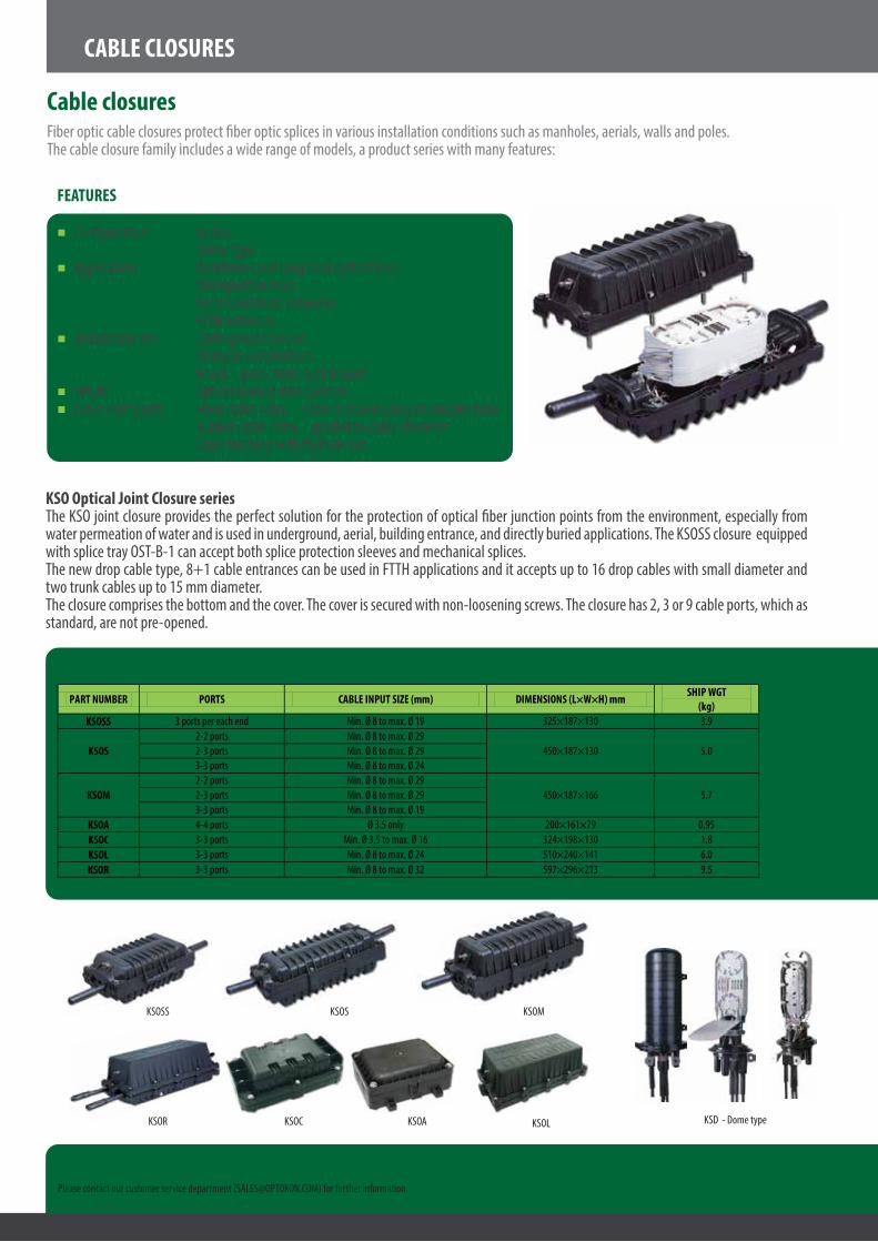
Fiber optic cable closures protect �ber optic splices in various installation conditions such as manholes, aerials, walls and poles.The cable closure family includes a wide range of models, a product series with many features:
FEATURES
Con�guration: In-line Dome typeApplication: Backbones and long haul optical lines Metropolitan lines Access and local networks FTTH networksInstallation site: Underground buried Manhole installations Aerial – pole, mast, wall mount, OPGW Optical Ground Wire systemsCable inlet ports: Fixed cable entry – cable is sealed using shrinkable tube Rubber cable entry – graded by cable diameter Cable bushing with �xation nut
KSO Optical Joint Closure series The KSO joint closure provides the perfect solution for the protection of optical �ber junction points from the environment, especially from water permeation of water and is used in underground, aerial, building entrance, and directly buried applications. The KSOSS closure equipped with splice tray OST-B-1 can accept both splice protection sleeves and mechanical splices. The new drop cable type, 8+1 cable entrances can be used in FTTH applications and it accepts up to 16 drop cables with small diameter and two trunk cables up to 15 mm diameter. The closure comprises the bottom and the cover. The cover is secured with non-loosening screws. The closure has 2, 3 or 9 cable ports, which as standard, are not pre-opened.
Please contact our customer service department ([email protected]) for further information
New
KSOSS
KSOR KSOC KSOA KSOL
KSOS KSOM
TECHNICAL SPECIFICATIONS
PART NUMBER PORTS CABLE INPUT SIZE (mm) DIMENSIONS (L×W×H) mm SHIP WGT (kg)
KSOSS 3 ports per each end Min. Ø 8 to max. Ø 19 325×187×130 3.9
KSOS 2-2 ports Min. Ø 8 to max. Ø 29
450×187×130 5.0 2-3 ports Min. Ø 8 to max. Ø 29 3-3 ports Min. Ø 8 to max. Ø 24
KSOM 2-2 ports Min. Ø 8 to max. Ø 29
450×187×166 5.7 2-3 ports Min. Ø 8 to max. Ø 29 3-3 ports Min. Ø 8 to max. Ø 19
KSOA 4-4 ports Ø 3.5 only 200×161×79 0.95 KSOC 3-3 ports Min. Ø 3.5 to max. Ø 16 324×198×130 1.8 KSOL 3-3 ports Min. Ø 8 to max. Ø 24 510×240×141 6.0 KSOR 3-3 ports Min. Ø 8 to max. Ø 32 597×296×213 9.5
KSD - Dome type

OPTOKON, a.s. reserves the right to make changes without notice to the products described in this document, in the interest of improving design, operational function and/or reliability.
Fiber optic technology leadership23 years experience on the global �ber optic marketNATO supplier code: 1583GMore than 14 years experience of supplying the militaries of over 20 countriesNational Security Authority certi�edISO and AQAP certi�edAccredited Calibration Laboratory No. 2315
OPTOKONOPTOKON, a.s. is a leading global producer and supplier of premium active and passive �ber optic components specializing in fully tested integrated data network, FTTx and tactical military solutions. Our components and solutions can be found in applications in businesses, communities and armed forces throughout the world.
OPTOKON, a.s., Červený Kříž 250, 586 01 Jihlava, Czech Republictel. +420 564 040 111, fax +420 564 040 134,
WWW.OPTOKON.COM, [email protected]
OPTOKON PORTFOLIO, SERVICES & DIVISIONSFIBER OPTIC DIVISION - Connectors, Cable Assemblies - Cable Management Systems - Splitters, WDM, CWDM and DWDM - Data Network Equipment - Test Equipment - Harsh Environment Optical Network - Service and Calibration CenterSERVICE DIVISIONMANAGEMENT & CONTROL DIVISION (SCADA)AIR CONDITIONING AND COOLING DIVISION
OPTOKON GROUP HEADQUARTERS PRODUCTION & RESEARCH CENTER
CZECH REPUBLIC
OPTOKON, a.s.Červený Kříž 250, JihlavaOPTOKON Prague O�ceVenušina 1149/3, Prague 10
OPTOKON Polska Sp. z o.o.
OPTOKON Ukraine LLC
OPTOKON Slovenia d.o.o.
OPTOKON Baltic SIA
OPTOKON Serbia, Representative O�ce
OptoNET Communication spol. s r.o.
OPTOKON ARABIAN LTD.Commercial, Technical & Service Support for Near Middle East
Your local partner
EUROPEAN UNIONEUROPEAN REGIONAL DEVELOPMENT FUNDINVESTMENT IN YOUR FUTURE