Operators Manual - VB36 Master Bowlturner Lathe operators manual read this manual carefully...
31
1 Operators Manual Issue 08/2015
Transcript of Operators Manual - VB36 Master Bowlturner Lathe operators manual read this manual carefully...

1
Operators Manual Issue 08/2015

2
Operators Manual READ THIS MANUAL CAREFULLY BEFORECONNECTING THE MACHINE TO THE POWER SUPPLY AND OPERATING. FAILURE TO DO SO COULD ENDANGER YOUR SAFETY!
Important Lubrication Information This lathe is extremely smooth running with the largest workpieces. This
is achieved to a large extent by fitting cast iron sleeve bearings and phosphor bronze thrust washers. These bearings, unlike ball bearings,
require regular maintenance. Keep the oil reservoirs topped up and grease the thrust washers at least once a month and once a week if
working regularly between centres.

3
Manufacturer: DRECHSELZENTRUM ERZGEBIRGE – steinert® Heuweg 4 09526 Olbernhau GERMANY Phone: +49 (0)37360-72456 Fax: +49 (0)37360-71919 E-Mail: [email protected] Web: www.vb36.com
Designation of machine: Master Bowlturning Lathe Type: VB36E
CE - Declaration of Conformity We declare that this machine meets the Essential Health and Safety Requirements of Machinery Directive 2010/42/EC and subsequent amendments. Electrical control and its Components are in accordance with the Low Voltage (2006/95/EC) and EMC (2004/108/EC) Directives. (Harmonized standards applied: EN ISO 12100/1/2, EN ISO 13857, EN ISO 13850, EN ISO 13848/1, EN ISO 3746, EN ISO 11202, EN ISO 11204, EN 60 204 T 1, EN 1088) Signed_______________________________________
Roland Steinert (Owner) For and on behalf of DRECHSELZENTRUM ERZGEBIRGE – steinert® Explanation of Symbols:
Read this passage carefully Wear safety spectacles Wear dust mask
Warranty
DRECHSELZENTRUM ERZGEBIRGE-steinert® warranties this lathe for a period of 10 years against manufacturing defect and will replace free of charge any part, of their manufacture, which fails due to such defect. This warranty does not cover any parts
which are considered consumables. Warranty of any electrical components is restricted to one year from the date of purchase in accordance with the warranties issued by the
manufacturers of those components. The limit of the liability under this warranty is restricted to parts and labour in Germany
and parts only in any other region of the world. Under the terms of this warranty the following are considered consumables:
Thrust washers (2 Year Warranty), Drive belts (2 Year Warranty), Oil, Grease, Cork gripping strip on beam, Nylon bearing strip on beam, Rubber mechanism cover on beam.

4
1 SECTION 1 .............................................................................................................................................. 6
1.1 Technical Data ................................................................................................................................. 6
1.2 Delivery of machine ........................................................................................................................ 6
1.3 Operating instructions .................................................................................................................... 6
1.4 Defined application ......................................................................................................................... 7
1.5 Safety hints ...................................................................................................................................... 7
1.5.1 General safety regulations ....................................................................................................... 7
1.5.2 Operating the machine ............................................................................................................ 7
1.5.3 The operator ............................................................................................................................ 7
1.5.4 Before operating the machine. ................................................................................................ 8
1.5.5 While working .......................................................................................................................... 8
1.5.6 After operation ........................................................................................................................ 8
1.6 Remaining risk ................................................................................................................................. 8
1.7 Mains connection: ........................................................................................................................... 9
1.8 Disclaimer: ....................................................................................................................................... 9
2 SECTION 2: ........................................................................................................................................... 10
2.1 INSTALLATION ............................................................................................................................... 10
2.1.1 FLOOR FIXING: ....................................................................................................................... 10
2.1.2 TYPE OF FLOORING: ............................................................................................................... 10
2.1.3 SITING: ................................................................................................................................... 10
2.1.4 TAILSTOCK FIXING: ................................................................................................................. 10
2.2 RUNNING-IN .................................................................................................................................. 12
2.2.1 RUNNING-IN PROCEDURE: .................................................................................................... 12
2.2.2 VB-LUBE: ................................................................................................................................ 12
2.2.3 THRUST BEARINGS: ................................................................................................................ 13
2.3 SPEED SELECTION .......................................................................................................................... 13
2.3.1 SAFETY: .................................................................................................................................. 13
2.3.2 CHANGING SPEEDS: ............................................................................................................... 13
2.3.3 BELT TENSION CONTROL: ...................................................................................................... 14
2.3.4 HAND CONTROL UNIT: ........................................................................................................... 14
2.3.5 RUNNING IN REVERSE:........................................................................................................... 15
2.4 MAINTENANCE .............................................................................................................................. 16
2.4.1 MAIN BEARINGS: ................................................................................................................... 16
2.4.2 THRUST BEARING LUBRICATION: .......................................................................................... 16
2.4.3 THRUST BEARING ADJUSTMENT: .......................................................................................... 16
2.4.4 BELT TENSION ADJUSTMENT: ................................................................................................ 18
2.4.5 TOOLREST BEAM: ................................................................................................................... 18
2.4.6 TOOLRESTS: ............................................................................................................................ 19

5
2.4.7 FITTING A REPLACEMENT BELT: ............................................................................................ 19
2.4.8 DRIVE PULLEY ALIGNMENT: ................................................................................................... 20
2.5 HEALTH AND SAFETY ..................................................................................................................... 21
2.5.1 CLOTHING: ............................................................................................................................. 21
2.5.2 LIGHTING: .............................................................................................................................. 21
2.5.3 THE WORKING AREA: ............................................................................................................. 22
2.5.4 FIRE PREVENTION: ................................................................................................................. 22
2.5.5 DUST EXTRACTION: ................................................................................................................ 22
2.5.6 FIRST AID: ............................................................................................................................... 22
2.6 WORKING WITH THE VB36E.......................................................................................................... 23
2.6.1 INTRODUCTION: ..................................................................................................................... 23
2.6.2 FACEPLATES: .......................................................................................................................... 23
2.6.3 IMPROVED FACEPLATE SEATING: .......................................................................................... 23
2.6.4 EXPANDING AND CONTRACTING JAW CHUCKS: ................................................................... 24
2.6.5 INCREASED CHUCK LOADING POTENTIAL BY VIRTUE OF THE TAILSTOCK: ........................... 24
2.6.6 MOUNTING WORK ON THE LATHE: ....................................................................................... 24
2.6.7 MECHANICAL LOADING: ........................................................................................................ 25
2.6.8 TOOLREST POSITIONING: ....................................................................................................... 25
2.6.9 BENNISON ADAPTER. ............................................................................................................. 25
2.6.10 BEFORE SWITCHING ON: ....................................................................................................... 25
2.6.11 SWITCHING ON: ..................................................................................................................... 26
2.6.12 SWITCHING OFF: .................................................................................................................... 26
2.6.13 ON/OFF FOOT CONTROL: ...................................................................................................... 26
2.7 TAILSTOCK ASSEMBLY ................................................................................................................... 27
2.7.1 CENTRE ALIGNMENT: ............................................................................................................. 27
2.7.2 TAILSTOCK BODY POSITIONING: ............................................................................................ 29
2.7.3 TAILSTOCK QUILL ADJUSTMENT: ........................................................................................... 29
2.7.4 TAILCENTRE REMOVAL: ......................................................................................................... 30
2.7.5 COMPLETE TAILSTOCK ASSEMBLY/ REMOVAL: ..................................................................... 30
2.7.6 TAILSTOCK RESTRAINING STRAP: .......................................................................................... 30
2.7.7 DRILL DEPTH GUIDE: .............................................................................................................. 30
2.7.8 MAINTENANCE: ..................................................................................................................... 30

6
1 SECTION 1
1.1 Technical Data
Motor: 240 Volt, 3 HP, 2.2kW, Three Phase, 1400 R.P.M
Supply Voltage: 220/240 volt 50 or 60 Cycles, Single Phase Spindle speeds: 3 Ranges
(1) 50 - 500 (2) 130-1390 (3) 245 - 2630
Distance between centres: 30in (762mm) (When fitted with bed extension): Centre height - over floor (choice of heights) : 46in or 43in (1165mm or 1090mm) - over toolrest beam : 36in (920mm) - over bed (if fitted) : 26in (660mm) Spindle nose Morse taper: : 3MT Outer spindle nose register : 60mm 0 (Bayonet type chuck mounting) Tailstock nose Morse taper : 3MT (when tailstock fitted) Quill travel on tailstock : 6in (150mm) (when tailstock fitted) Net weight of machine : 240 Kg (without beam, tailstock or accessories) Mains fuse : 13 amp
1.2 Delivery of machine
Check the following on receipt of the machine: - Packing for damage (Notify the delivery company and VB Manufacturing of any damage immediately) - Contents against despatch note (VB Manufacturing will not accept any responsibility for any shortages not notified within three days of delivery) Accessories when unpacking
1.3 Operating instructions
- Read the operating instructions carefully before using the machine. - We cannot accept liability for damage and accident arising from improper use.

7
1.4 Defined application
- The VB36E bowlturning lathes are exclusively made for the turning of round wooden workpieces. - Do not use the machine for any purpose other than that recommended by the manufacturer. - The machine may only be used and handled by persons who are familiar with the machine and have been informed of the safety regulations. - In order to avoid accidents it is absolutely necessary that all safety regulations as well as other generally acknowledged safety rules are adhered to. - Only original VB36E MASTER BOWLTURNER spare parts may be used. - Neither VB Manufacturing nor their agents & distributors will hold themselves liable under the warranty for damage caused by using non-original VB36E MASTER BOWLTURNER spare parts. - Any alterations or modification to the machine exclude the manufacturer and supplier from any liability.
1.5 Safety hints
1.5.1 General safety regulations
- Keep unauthorised adults as well as children away from the machine
1.5.2 Operating the machine
- Most types of wood produce unhealthy dust emission during the turning process. For this reason the machine should be used in conjunction with an extraction system.
1.5.3 The operator
In order to minimise risk of accidents, study the operating instructions well before starting to work. - Never work under the influence of alcohol, drugs or medication. - Do not wear loose fitting clothing. - Do not wear watches , bracelets, finger rings or ties. - Always wear safety goggles or spectacles. - Wear a dust mask, as extraction systems are never 100% efficient.
8
1.5.4 Before operating the machine.
Before switching on the machine check the following: - Rotation speed: Check position of the drive belt (and setting of the speed control on VB36E). Large, heavy and unbalanced workpieces should always be turned initially at the lowest operational speed. The circumferal speed should not exceed 30 m/s - Location of Tailstock Quill: Check the centre is fully home in the tailstock to avoid vibration when turning heavy pieces between centres. Vibration may occur if the centre or quill are not securely in position and locked tight. - Mandrel Shaft: Must be disengaged from the spindle locking mechanism before starting. - Tool Rest: You should always turn the workpiece by hand before starting the machine to make sure that the tool rest does not foul the workpiece. Adjust the position of the toolrest before switching the machine on. Adjustments to the toolrest while the machine is running are dangerous. - Secure all tensioning levers: Make sure all tension levers and nuts are firmly tightened so as not to work loose while the machine is in operation.
1.5.5 While working
Do not adjust the tool rest. Do not open machine headstock cover. Do not touch the workpiece with your fingers. The machine must only be cleaned when it has been switched off.
1.5.6 After operation
Never leave the machine unattended while it is operating. Remain at the machine until it has come to a complete standstill. Disconnect the machine from the mains supply.
1.6 Remaining risk
It is possible that the following remaining risk can still occur in spite of observing all the Relevant safety regulations due to the nature of the operations for which the machine has been constructed. - Touching live wires due to damage to the cable lead and its connection to the plug or the machine. - Workpiece splinters. - Tools getting stuck in the workpiece and “snatching” - Your sense of hearing may suffer due to continuous use of the machine without ear defenders. - Inhalation of dust which may be harmful to health.

9
1.7 Mains connection:
- Check that the voltage on the motor manufacturer’s label corresponds with the voltage of the power source. - Only qualified electricians should be allowed to carry out electrical work. - Check if motor is rotating in the correct direction.
1.8 Disclaimer:
DRECHSELZENTRUM ERZGEBIRGE –steinert reserves the right to make changes to the specification of the VB36 as part of the products continuing development. These changes may not be reflected in this manual and up to date information can be obtained from the DRECHSELZENTRUM ERZGEBIRGE –steinert technical support email [email protected]
10
2 SECTION 2:
2.1 INSTALLATION
2.1.1 FLOOR FIXING:
The VB36 is designed to carry the widest range of loads, from the very small, to such sizes as can only be safely loaded onto the mandrel nose with the help of mechanical lifting gear. The forces generated in turning overhanging loads in particular may create instabilities and it is recommended that the headstock floorstand, and tailstock leg (if fitted), be bolted to the floor.
2.1.2 TYPE OF FLOORING:
It is important that the floor is sound and level in all planes under the lathe stand and tailstock leg. Uneven flooring will create unnecessary stresses in the lathe stand and headstock. Any gaps between the floor and the mounting holes in the stand must be taken up with appropriate material (rubber mounting supplied) before the fixing bolts or screws are tightened. The type of flooring is less critical and almost any flooring that is designed to carry pedestrian traffic will do, be it timber, concrete or composite board. Flooring which is considered to be too insubstantial can be reinforced locally with a floorplate, or reconstructed in stronger material in the area where the lathe is to be sited.
2.1.3 SITING:
Use a tracing of the scale plan of the cabinet stand (VB40) and toolrest beam (VB101) to determine the best position for the lathe. It will be seen that the beam projects through the stand to the rear and left hand side. It may not be necessary to allow for maximum clearance behind both these faces, as the range of positions required at the operating end of the beam (where the toolrest is) are attainable in many different ways. Experimentation with various square and angled sitings will reveal the optimum siting relative to your available working space. The space required behind the headstock unit for the beam will of course be generally
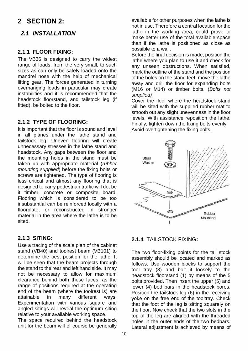
available for other purposes when the lathe is not in use. Therefore a central location for the lathe in the working area, could prove to make better use of the total available space than if the lathe is positioned as close as possible to a wall. Before the final decision is made, position the lathe where you plan to use it and check for any unseen obstructions. When satisfied, mark the outline of the stand and the position of the holes on the stand feet, move the lathe away and drill the floor for expanding bolts (M16 or M14) or timber bolts. (Bolts not supplied) Cover the floor where the headstock stand will be sited with the supplied rubber mat to smooth out any slight unevenness in the floor levels. With assistance reposition the lathe. Finally, tighten down the fixing bolts evenly. Avoid overtightening the fixing bolts.
2.1.4 TAILSTOCK FIXING:
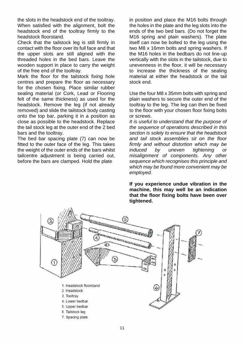
The two floor-fixing points for the tail stock assembly should be located and marked as follows. Use wooden blocks to support the tool tray (3) and bolt it loosely to the headstock floorstand (1) by means of the 5 bolts provided. Then insert the upper (5) and lower (4) bed bars in the headstock bores. Position the tailstock leg (6) in the receiving yoke on the free end of the tooltray. Check that the foot of the leg is sitting squarely on the floor. Now check that the two slots in the top of the leg are aligned with the threaded holes in the outer ends of the two bedbars. Lateral adjustment is achieved by means of
11
the slots in the headstock end of the tooltray. When satisfied with the alignment, bolt the headstock end of the tooltray firmly to the headstock floorstand. Check that the tailstock leg is still firmly in contact with the floor over its full face and that the upper slots are still aligned with the threaded holes in the bed bars. Leave the wooden support in place to carry the weight of the free end of the tooltray. Mark the floor for the tailstock fixing hole centres and prepare the floor as necessary for the chosen fixing. Place similar rubber sealing material (or Cork, Lead or Flooring felt of the same thickness) as used for the headstock. Remove the leg (if not already removed) and slide the tailstock body casting onto the top bar, parking it in a position as close as possible to the headstock. Replace the tail stock leg at the outer end of the 2 bed bars and the tooltray. The bed bar spacing plate (7) can now be fitted to the outer face of the leg. This takes the weight of the outer ends of the bars whilst tailcentre adjustment is being carried out, before the bars are clamped. Hold the plate
in position and place the M16 bolts through the holes in the plate and the leg slots into the ends of the two bed bars. (Do not forget the M16 spring and plain washers). The plate itself can now be bolted to the leg using the two M8 x 16mm bolts and spring washers. If the M16 holes in the bedbars do not line-up vertically with the slots in the tailstock, due to unevenness in the floor, it will be necessary to increase the thickness of the sealing material at either the headstock or the tail stock end. Use the four M8 x 35mm bolts with spring and plain washers to secure the outer end of the tooltray to the leg. The leg can then be fixed to the floor with your chosen floor fixing bolts or screws. It is useful to understand that the purpose of the sequence of operations described in this section is solely to ensure that the headstock and tail stock assemblies sit on the floor firmly and without distortion which may be induced by uneven tightening or misalignment of components. Any other sequence which recognises this principle and which may be found more convenient may be employed. If you experience undue vibration in the machine, this may well be an indication that the floor fixing bolts have been over tightened.

12
2.2 RUNNING-IN
2.2.1 RUNNING-IN PROCEDURE:
Plain bearings need to be “run-in” over a period of time before they are ready for continuous high speed operation. This allows the bearing surfaces to adapt to each other and for microscopic irregularities to be removed. Preliminary running-in of every VB36 is carried out as part of its manufacturing and proving programme. Over an eight hour period, each lathe is put through a cycle of various speed/duration operations that prepares it for general turning duties. Even so, your lathe will benefit from your attention to its early working life requirements. The first thing you will notice is that plain bearings are designed to run at considerably higher temperatures than other types of bearing. This is normal and acceptable. It is a primary indication that the bearings are running without excessive clearance. The energy generated in the lubricant film at the bearing interface is dissipated as heat through the bearing housings and mandrel shaft. Higher operational speeds generate proportionally higher temperatures. After 20 minutes of operation at speeds around 1500rpm, the bearing housing should be hot to touch, but not so hot that the palm of your hand cannot be held against it. It is helpful to the running-in process if you run the lathe for long periods at speeds below 1,000rpm and periodically accelerate the drive to over 2,000rpm for brief periods. (Starting with five minute periods and increasing slowly to 15 minute periods). Within a week you will then be able to run it continuously at high speeds. CAUTION: HIGH SPEED OPERATION MUST NEVER BE UNDERTAKEN IF AN UNSUITABLE WORKPIECE IS LOADED. (See Section 2.3: SPEED SELECTION) If you detect signs of excessive turning resistance, (i.e., more than when the lathe is cold), switch off and wait for a few minutes until the shaft can be rotated freely again. As the bearings cool, so oil is drawn into their semi-porous surface. Oil levels in the filler
cups must therefore be checked frequently until the bearings are fully charged. After about 50 hours of varied use the lathe will be fully run in.
2.2.2 VB-LUBE:
This is a highly sophisticated lubricant which has the unusual property of combining electro-chemically with sub-micron size wear particles at the bearing surfaces in early life. A new organo-metallic compound is formed and becomes the sacrificial layer between the bearings and the shaft. The film strength is such that, after running-in, direct shaft-to-bearing contact is virtually eliminated and superlative bearing performance is assured.
13
2.2.3 THRUST BEARINGS:
These are located on the mandrel shaft inboard and outboard of the rear mainbearing and require occasional adjustment. (See Section 2.4: MAINTENANCE)
2.3 SPEED SELECTION
2.3.1 SAFETY:
Selection of an appropriate speed for the work you are turning is a major factor with regard to safety. The golden rule is therefore: ALWAYS BEGIN TURNING UNFAMILIAR WORK AT A SLOW SPEED. THIS IS PARTICULARLY TRUE FOR NON-CIRCULAR AND GLUED WORKPIECES. As you observe its state of balance or imbalance and the effect this has on the stability of the lathe, the speed may be progressively increased until vibration is observed, or the work is running at a sufficiently high speed for your purpose. Workpiece diameter alone is not a sufficient guide as to what might be a suitable turning speed. A relatively small workpiece can exert substantial forces on the lathe and the work-holding device if it is off centre or naturally unbalanced. Conversely, a very large diameter workpiece which is perfectly balanced will run smoothly at a higher speed. The best guide to speed selection is your own experience and observation of different types of work. The relative strength of the work holding device (faceplate, multi-jaw, spigot chuck etc.) will also have a bearing on the selection of a safe turning speed. A slower turning speed will simply require slower tool movement in order to avoid leaving a screwthread trail. The chart must therefore be regarded as an approximate guide to speed selection for different diameters and types of work. Bearing in mind all the factors mentioned above, speeds should not be selected from the chart as a definitive recommendation.
The suggestions should rather be viewed as MAXIMUMS for any particular category of work. All the speeds below these maximums are available and should be used freely.
2.3.2 CHANGING SPEEDS:
The primary belt drive on the VB36 has 3 steps. Calculate which of the steps will allow the lathe motor to run across the speed range you will require for the execution of your work. For example, if you are turning a workpiece that you estimate will need speeds between 300 and 500rpm, you could theoretically use any of the 3 ratios. However, the selection of the lower speed ratio would be correct. In the lower speed ratio you would be turning towards top of the speed range, with the motor running at the top of its power capabilities, and in the higher speed ratio you would be turning at the very bottom of the speed range, where little power would be available to turn a large workpiece against a heavy cut. Always try and choose a motor pulley step where the desired speeds are in the top two thirds of its speed range. For example, the middle pulley ratio offers a range of between 150-1350rpm and speeds in the range of 500 to 1350rpm are ideal on this pulley, where the motor will be running comfortably with maximum power output. Having decided on an appropriate speed range for the work, SWITCH OFF the lathe before opening the transmission access door. Slacken the belt tension by turning the BELT TENSION CONTROL HANDLE to the left of the door anti-clockwise. Move the belt to the appropriate drive and mandrel shaft pulleys. Re-tension the belt by turning the control handle clockwise. (See Section 2.3.3: BELT TENSION CONTROL) It will be seen that the low speed ratio (i.e. the smallest diameter motor pulley that drives the largest mandrel shaft pulley) has grooves for two belts to be used side by side. Normally only the 10 rib belt will be needed to transmit sufficient power to keep the work turning against the cutting force of the tool you are using. In the most demanding circumstances however, the 5 rib belt can be brought into use alongside the 10 rib. The middle

14
ratioemploys just the 10 rib belt, the high speed ratio requires only the 5 rib belt to transmit the full motor power. The belt which is not in use should be parked, on the hooks provided, on the inner roof of the casting.
2.3.3 BELT TENSION CONTROL:
The handle which controls the belt tension is situated on the near face of the headstock casting just to the left of the transmission access door. Turning the handle clockwise increases the belt tension; anti-clockwise decreases it. Only moderate tension is required for the system to function efficiently. To achieve the correct tension, slowly lower the motor by turning the tension handle clockwise until you reach a point where the turning resistance becomes slack (At this point the belt is supporting the motor and taking the pressure off the tension screw.), then turn the handle a further 1/4 to 1/2 of a revolution. The belt is now correctly tensioned. Overtensioning of the belt will seriously reduce the belt life and the life of the motor bearings.
2.3.4
15
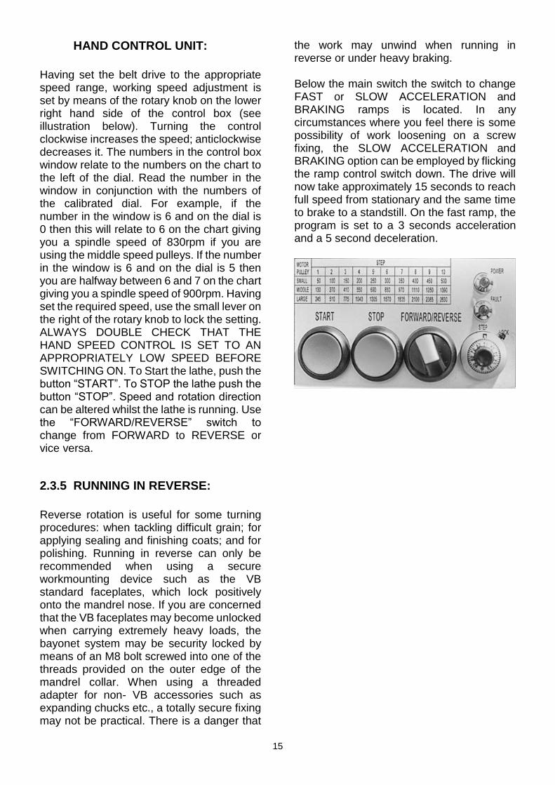
HAND CONTROL UNIT:
Having set the belt drive to the appropriate speed range, working speed adjustment is set by means of the rotary knob on the lower right hand side of the control box (see illustration below). Turning the control clockwise increases the speed; anticlockwise decreases it. The numbers in the control box window relate to the numbers on the chart to the left of the dial. Read the number in the window in conjunction with the numbers of the calibrated dial. For example, if the number in the window is 6 and on the dial is 0 then this will relate to 6 on the chart giving you a spindle speed of 830rpm if you are using the middle speed pulleys. If the number in the window is 6 and on the dial is 5 then you are halfway between 6 and 7 on the chart giving you a spindle speed of 900rpm. Having set the required speed, use the small lever on the right of the rotary knob to lock the setting. ALWAYS DOUBLE CHECK THAT THE HAND SPEED CONTROL IS SET TO AN APPROPRIATELY LOW SPEED BEFORE SWITCHING ON. To Start the lathe, push the button “START”. To STOP the lathe push the button “STOP”. Speed and rotation direction can be altered whilst the lathe is running. Use the “FORWARD/REVERSE” switch to change from FORWARD to REVERSE or vice versa.
2.3.5 RUNNING IN REVERSE:
Reverse rotation is useful for some turning procedures: when tackling difficult grain; for applying sealing and finishing coats; and for polishing. Running in reverse can only be recommended when using a secure workmounting device such as the VB standard faceplates, which lock positively onto the mandrel nose. If you are concerned that the VB faceplates may become unlocked when carrying extremely heavy loads, the bayonet system may be security locked by means of an M8 bolt screwed into one of the threads provided on the outer edge of the mandrel collar. When using a threaded adapter for non- VB accessories such as expanding chucks etc., a totally secure fixing may not be practical. There is a danger that
the work may unwind when running in reverse or under heavy braking. Below the main switch the switch to change FAST or SLOW ACCELERATION and BRAKING ramps is located. In any circumstances where you feel there is some possibility of work loosening on a screw fixing, the SLOW ACCELERATION and BRAKING option can be employed by flicking the ramp control switch down. The drive will now take approximately 15 seconds to reach full speed from stationary and the same time to brake to a standstill. On the fast ramp, the program is set to a 3 seconds acceleration and a 5 second deceleration.
16
2.4 MAINTENANCE
Very little general maintenance is required to keep the VB36 running in perfect condition, but particular attention must be paid to lubrication requirements. These, and such other adjustments as may be necessary from time to time, are detailed below.
2.4.1 MAIN BEARINGS:
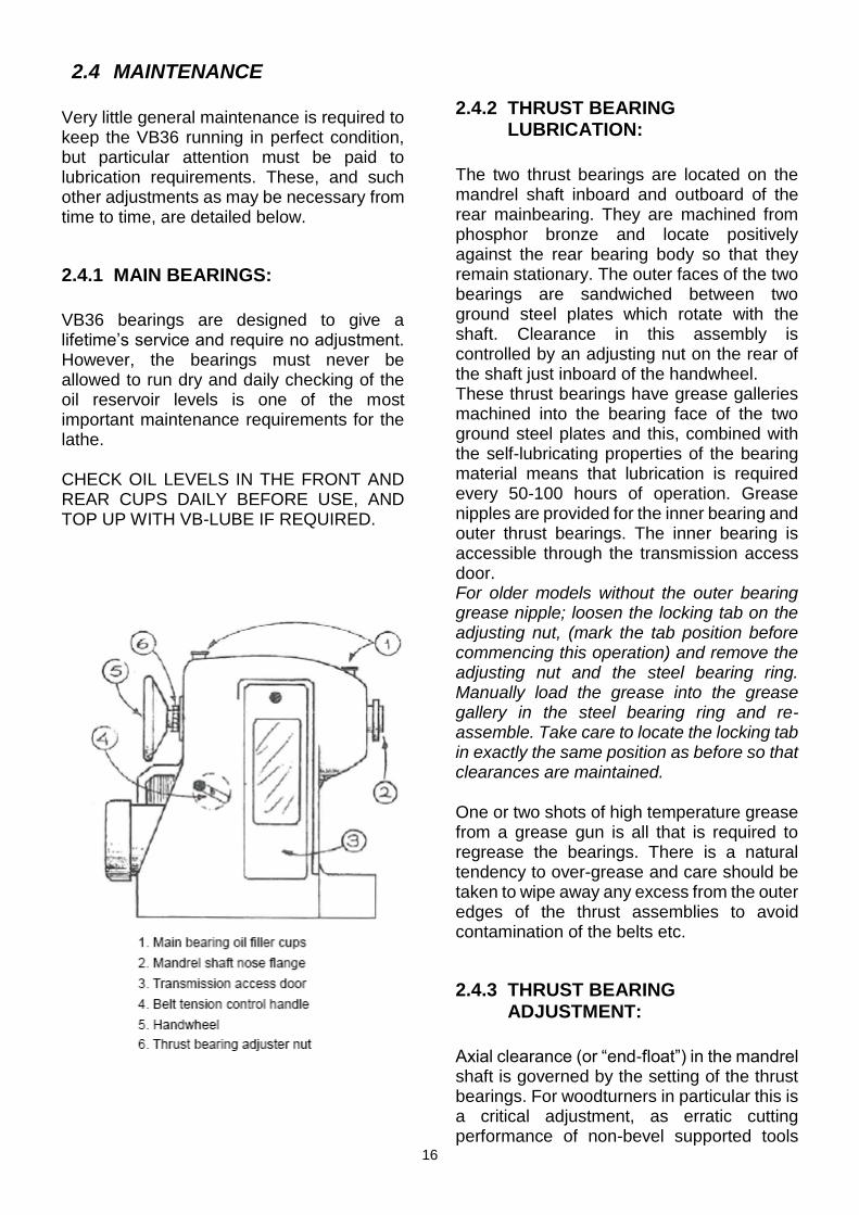
VB36 bearings are designed to give a lifetime’s service and require no adjustment. However, the bearings must never be allowed to run dry and daily checking of the oil reservoir levels is one of the most important maintenance requirements for the lathe. CHECK OIL LEVELS IN THE FRONT AND REAR CUPS DAILY BEFORE USE, AND TOP UP WITH VB-LUBE IF REQUIRED.
2.4.2 THRUST BEARING LUBRICATION:
The two thrust bearings are located on the mandrel shaft inboard and outboard of the rear mainbearing. They are machined from phosphor bronze and locate positively against the rear bearing body so that they remain stationary. The outer faces of the two bearings are sandwiched between two ground steel plates which rotate with the shaft. Clearance in this assembly is controlled by an adjusting nut on the rear of the shaft just inboard of the handwheel. These thrust bearings have grease galleries machined into the bearing face of the two ground steel plates and this, combined with the self-lubricating properties of the bearing material means that lubrication is required every 50-100 hours of operation. Grease nipples are provided for the inner bearing and outer thrust bearings. The inner bearing is accessible through the transmission access door. For older models without the outer bearing grease nipple; loosen the locking tab on the adjusting nut, (mark the tab position before commencing this operation) and remove the adjusting nut and the steel bearing ring. Manually load the grease into the grease gallery in the steel bearing ring and re-assemble. Take care to locate the locking tab in exactly the same position as before so that clearances are maintained. One or two shots of high temperature grease from a grease gun is all that is required to regrease the bearings. There is a natural tendency to over-grease and care should be taken to wipe away any excess from the outer edges of the thrust assemblies to avoid contamination of the belts etc.
2.4.3 THRUST BEARING ADJUSTMENT:
Axial clearance (or “end-float”) in the mandrel shaft is governed by the setting of the thrust bearings. For woodturners in particular this is a critical adjustment, as erratic cutting performance of non-bevel supported tools
17
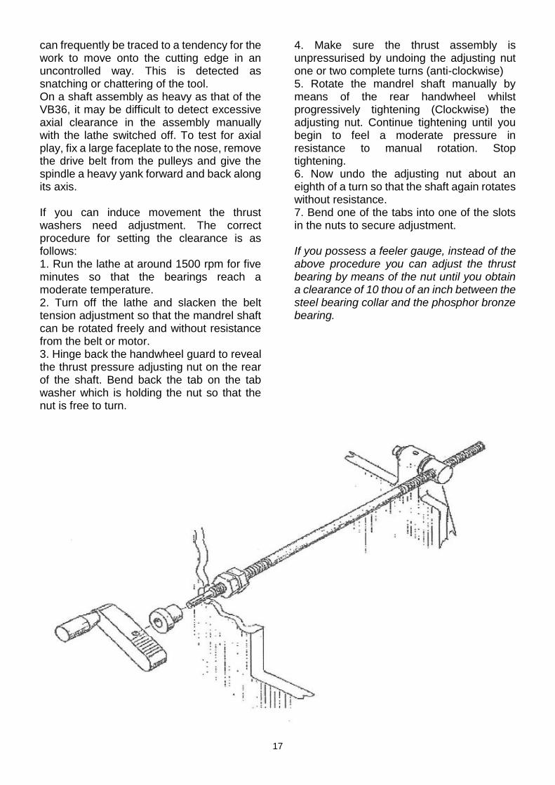
can frequently be traced to a tendency for the work to move onto the cutting edge in an uncontrolled way. This is detected as snatching or chattering of the tool. On a shaft assembly as heavy as that of the VB36, it may be difficult to detect excessive axial clearance in the assembly manually with the lathe switched off. To test for axial play, fix a large faceplate to the nose, remove the drive belt from the pulleys and give the spindle a heavy yank forward and back along its axis. If you can induce movement the thrust washers need adjustment. The correct procedure for setting the clearance is as follows: 1. Run the lathe at around 1500 rpm for five minutes so that the bearings reach a moderate temperature. 2. Turn off the lathe and slacken the belt tension adjustment so that the mandrel shaft can be rotated freely and without resistance from the belt or motor. 3. Hinge back the handwheel guard to reveal the thrust pressure adjusting nut on the rear of the shaft. Bend back the tab on the tab washer which is holding the nut so that the nut is free to turn.
4. Make sure the thrust assembly is unpressurised by undoing the adjusting nut one or two complete turns (anti-clockwise) 5. Rotate the mandrel shaft manually by means of the rear handwheel whilst progressively tightening (Clockwise) the adjusting nut. Continue tightening until you begin to feel a moderate pressure in resistance to manual rotation. Stop tightening. 6. Now undo the adjusting nut about an eighth of a turn so that the shaft again rotates without resistance. 7. Bend one of the tabs into one of the slots in the nuts to secure adjustment. If you possess a feeler gauge, instead of the above procedure you can adjust the thrust bearing by means of the nut until you obtain a clearance of 10 thou of an inch between the steel bearing collar and the phosphor bronze bearing.
18
2.4.4 BELT TENSION ADJUSTMENT:
The belt tension control handle is located on the near side of the headstock casting close to the transmission access door. The handle drives a threaded rod which runs into a pivoting nut (called the TENSION ROD PIN) linked to the motor mounting plate. All moving parts, including the control handle bush, (where it passes through the casting), the thread, (where it passes through the tension rod pin) and the tension rod pin, (where its shaft passes through the motor mounting plate), should be lubricated with a light machine oil (or VB-Lube) every 50 hours or so. A small hole is provided for lubricating the shaft of the tension rod pin on the top of the motor mounting plate. The two nuts on the tension rod can be adjusted to eliminate backlash in the winding mechanism.
2.4.5 TOOLREST BEAM:
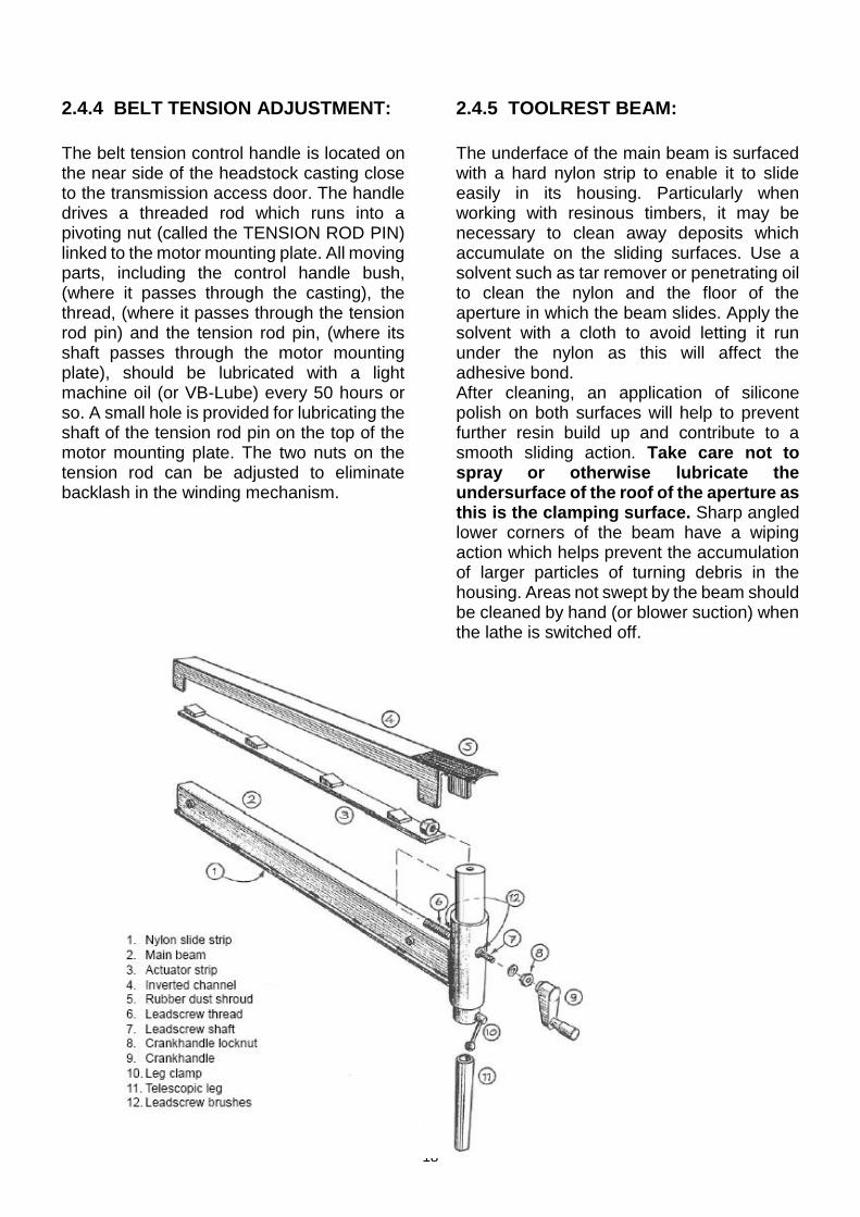
The underface of the main beam is surfaced with a hard nylon strip to enable it to slide easily in its housing. Particularly when working with resinous timbers, it may be necessary to clean away deposits which accumulate on the sliding surfaces. Use a solvent such as tar remover or penetrating oil to clean the nylon and the floor of the aperture in which the beam slides. Apply the solvent with a cloth to avoid letting it run under the nylon as this will affect the adhesive bond. After cleaning, an application of silicone polish on both surfaces will help to prevent further resin build up and contribute to a smooth sliding action. Take care not to spray or otherwise lubricate the undersurface of the roof of the aperture as this is the clamping surface. Sharp angled lower corners of the beam have a wiping action which helps prevent the accumulation of larger particles of turning debris in the housing. Areas not swept by the beam should be cleaned by hand (or blower suction) when the lathe is switched off.
19
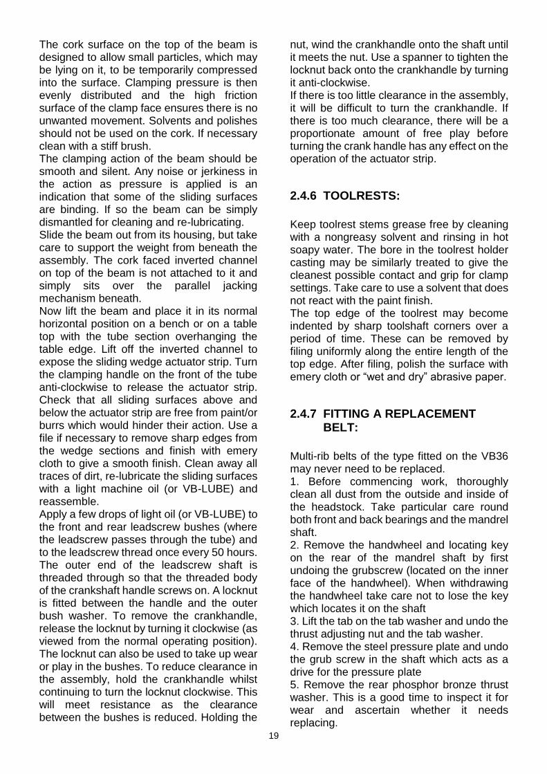
The cork surface on the top of the beam is designed to allow small particles, which may be lying on it, to be temporarily compressed into the surface. Clamping pressure is then evenly distributed and the high friction surface of the clamp face ensures there is no unwanted movement. Solvents and polishes should not be used on the cork. If necessary clean with a stiff brush. The clamping action of the beam should be smooth and silent. Any noise or jerkiness in the action as pressure is applied is an indication that some of the sliding surfaces are binding. If so the beam can be simply dismantled for cleaning and re-lubricating. Slide the beam out from its housing, but take care to support the weight from beneath the assembly. The cork faced inverted channel on top of the beam is not attached to it and simply sits over the parallel jacking mechanism beneath. Now lift the beam and place it in its normal horizontal position on a bench or on a table top with the tube section overhanging the table edge. Lift off the inverted channel to expose the sliding wedge actuator strip. Turn the clamping handle on the front of the tube anti-clockwise to release the actuator strip. Check that all sliding surfaces above and below the actuator strip are free from paint/or burrs which would hinder their action. Use a file if necessary to remove sharp edges from the wedge sections and finish with emery cloth to give a smooth finish. Clean away all traces of dirt, re-lubricate the sliding surfaces with a light machine oil (or VB-LUBE) and reassemble. Apply a few drops of light oil (or VB-LUBE) to the front and rear leadscrew bushes (where the leadscrew passes through the tube) and to the leadscrew thread once every 50 hours. The outer end of the leadscrew shaft is threaded through so that the threaded body of the crankshaft handle screws on. A locknut is fitted between the handle and the outer bush washer. To remove the crankhandle, release the locknut by turning it clockwise (as viewed from the normal operating position). The locknut can also be used to take up wear or play in the bushes. To reduce clearance in the assembly, hold the crankhandle whilst continuing to turn the locknut clockwise. This will meet resistance as the clearance between the bushes is reduced. Holding the
nut, wind the crankhandle onto the shaft until it meets the nut. Use a spanner to tighten the locknut back onto the crankhandle by turning it anti-clockwise. If there is too little clearance in the assembly, it will be difficult to turn the crankhandle. If there is too much clearance, there will be a proportionate amount of free play before turning the crank handle has any effect on the operation of the actuator strip.
2.4.6 TOOLRESTS:
Keep toolrest stems grease free by cleaning with a nongreasy solvent and rinsing in hot soapy water. The bore in the toolrest holder casting may be similarly treated to give the cleanest possible contact and grip for clamp settings. Take care to use a solvent that does not react with the paint finish. The top edge of the toolrest may become indented by sharp toolshaft corners over a period of time. These can be removed by filing uniformly along the entire length of the top edge. After filing, polish the surface with emery cloth or “wet and dry” abrasive paper.
2.4.7 FITTING A REPLACEMENT BELT:
Multi-rib belts of the type fitted on the VB36 may never need to be replaced. 1. Before commencing work, thoroughly clean all dust from the outside and inside of the headstock. Take particular care round both front and back bearings and the mandrel shaft. 2. Remove the handwheel and locating key on the rear of the mandrel shaft by first undoing the grubscrew (located on the inner face of the handwheel). When withdrawing the handwheel take care not to lose the key which locates it on the shaft 3. Lift the tab on the tab washer and undo the thrust adjusting nut and the tab washer. 4. Remove the steel pressure plate and undo the grub screw in the shaft which acts as a drive for the pressure plate 5. Remove the rear phosphor bronze thrust washer. This is a good time to inspect it for wear and ascertain whether it needs replacing.

20
6. Slacken the two grubscrews which secure the mandrel shaft pulley to the shaft. One is on the boss at the front of the pulley. The other is entered at a 30° angle on the hub at the rear of the pulley. 7. Slide the pulley along the mandrel shaft towards the nose of the machine until the locating key for the pulley is fully exposed on the shaft. DO NOT WITHDRAW THE SHAFT UNTIL YOU HAVE REMOVED THE KEY. 8. With the keyway slot uppermost on the shaft so that it does not damage the front oil seals, withdraw the shaft from the back bearing, keeping the pulley at the nose end of the drive compartment, until there is just sufficient room to change the belts. CAUTION: TAKE CARE TO SUPPORT THE REAR OF THE MANDREL SHAFT SO AS NOT TO DAMAGE THE INNER BEARING SURFACE OF THE REAR BEARING AND THE OIL SEALS. 9. Change the belts hanging the new belts on the hooks provided on the inner roof of the headstock. 10. Check the condition of the inner phosphor bronze thrust washer and relocate it on the pins in the end of the rear bearing. 11. Reassemble by sliding the shaft back into the rear until the chrome bearing surface has passed through the outer oil seal and the inner thrust plate stops any further rearward movement of the shaft. NOTE: SOME RESISTANCE TO THE REFITTING OF THE SHAFT WILL BE EXPERIENCED AS THE MACHINED SHOULDERS CONTACT THE BEARING SEALS. CONTINUE EXERTING MODERATE PRESSURE WHILST ROTATING THE SHAFT TO EASE THE OILSEALS OPEN. 12. Refit the pulley key into the shaft. 13. Slide the pulley over the key. 14. Re-locate the rear phosphor bronze thrust washer on the two locating pins. 15. Replace the driving grubscrew in the end of the bearing surface and refit the outer thrust plate after reloading the grease gallery with high temperature grease. (Greasing can be left till after assembly with later models fitted with grease nipples). 16. Refit the tab washer and thrust adjuster nut.
17. Refit the handle using the keyway and tighten the retaining grubscrew. 18. Refill the oilcups, making sure feed tube is full. 19. Grease the inner thrust washer with high temperature grease, using the fitted grease nipple. 20. Align the pulleys as described in Section 2.4.8 21. Adjust the thrust end-float as described in Section 2.4.3 22. Run in at speeds up to 500 rpm. Use wire probe to release any air locks in oilpot feed tubes, refilling as necessary. Reverse motor occasionally to help circulate the oil round the bearings. 23. When satisfied oilways are full replace wicks.
2.4.8 DRIVE PULLEY ALIGNMENT:
Correct alignment of the pulleys is essential for the belt to give an even pull across its width. If the pulleys are vertically out of line the drive belt will tend to run over the shoulder of the groves and wear heavily. Such wear will lead to early failure of the belt. Unusual vibration, often accompanied by a squealing noise can be another symptom of pulley misalignment. To realign the pulleys proceed as follows: 1. Loosen the two grub screws front and back of the mandrel shaft pulley so that it can slide freely along the shaft. 2. With a straight edge such as a metal ruler, line up the front edge of the large motor wheel pulley with the front edge of the matching small pulley on the mandrel shaft. Slide the pulley along the shaft until they are in line. 3. Tighten one of the grub screws so that it is held on the shaft and check that the pulleys are still aligned correctly. 4. Place the 10 rib belt over the middle pulleys and tighten the tension adjuster. 5. Turn the mandrel shaft over by hand using the handwheel and check that there is no tendency for the belt to ride up on the pulley and change groves. 6. Close the access door and run the motor slowly to check for any belt noise that might indicate that the pulleys are not aligned correctly. N.B: Belt noise can also be caused by dirty pulleys, so clean the pulleys with

21
spirits and a wire brush and try again if belt noise is present. 7. When satisfied that the pulleys are running in line tighten the second grub screw on the mandrel shaft pulley.
2.5 HEALTH AND SAFETY
2.5.1 CLOTHING:
Do not wear loose clothing whilst operating the lathe. Neckties, trailing cuffs, flaps of clothing, uncovered woollen pullovers, hanging hair etc. are potential hazards if they come into contact with the rotating work. Rings in particular should be removed from fingers before operating any machinery. They are not hazardous in themselves but can be impossible to remove if a finger is accidentally bruised and swells. A minor and otherwise inconsequential injury can become serious in some circumstances. Wear appropriate shoes. Falling tools etc. could damage your feet. Wear safety glasses or a face mask. The vast majority of all reported accidents in industry involve injuries to unprotected eyes. Ear defenders are a “Health & Safety” requirement for machine operators. Although the noise from the VB36E throughout most of its speed range is low, the noise from the turning tool contacting the wood during some procedures (e.g., initial cuts on dried, part turned blanks) will be more intrusive.
2.5.2 LIGHTING:
Indirect natural light is best for evaluating colours and perspective. Fluorescent tubes give good general light but have a strobing effect which is tiresome to work in and can, at certain speeds, make the revolving work appear to be stationary. A shielded “Anglepoise” type, tungsten bulb lamp is most useful for local illumination, creating shadows, and masking the effects of the frequency oscillations of fluorescent strip lighting. The VB36 has mounting holes for the peg foot of an Anglepoise lamp in the headstock casting: Two over the access door and one on the protrusion that holds the end of the bottom bed bar. A moveable lamp can also be useful for gauging uniform wall thickness on some types of wet turning.
22
2.5.3 THE WORKING AREA:
Keep the floor area around your lathe clear of obstructions which could cause you to trip. Accumulation of waste can also give you an insecure footing and a tendency to slip. Do not store tools or other items where they could fall onto the lathe or workplace. Check trailing electrical leads for wear and damage regularly. WE WOULD RECOMMEND THAT THE POWER LEAD TO THE LATHE IS PLACED IN CONDUIT FROM THE POWER SOURCE TO THE LATHE ACROSS THE FLOOR OR DROPPED FROM THE CEILING.
2.5.4 FIRE PREVENTION:
Minimise fire risks by disposing of all combustible waste safely outside the workshop. Store bulk quantities of inflammable solvents, sealers, polishers, etc. in a metal container outside the workshop. Have a fire extinguisher suitable for use on electrical and chemical fires prominently sited in the working area.
2.5.5 DUST EXTRACTION:
Sanding dust is a potential health hazard and it is always advisable to wear a dust mask or air processing helmet when undertaking any operation that produces particles that float in the air. Mechanical waste extraction is feasible in many workshops, although, to date, all mobile extractors are comparatively noisy. True dust extractors (as opposed to general waste machines and chip extractors) also have to comply with regulations concerned with the increased risk of explosion. They must be enclosed in a metal (or brick) cabinet, have sparkproof motors and fans, and have explosion relief to free air - that is, air outside the workshop. Good ventilation in the working area will help to minimize the problem of airbourne dust.
2.5.6 FIRST AID:
Injuries to woodworkers who use modern equipment and who obey the basic operating rules are rare. Woodturning is by far the safest of all wood related activities as there are no rotating cutters. For this reason, first aid equipment is seldom considered as a priority by private workshop users. It is, however, a sensible precaution to have a basic selection of first aid items handy in any area where machinery or sharp tools are used - before they are actually needed. Extensive regulations govern the provision of first aid equipment for all workplaces which are covered by Health and Safety legislation. In a home workshop first aid will mostly be self administered and items should be chosen with this in mind. Proprietary first aid kits vary in potential usefulness and often fail to provide what would actually be needed to treat a serious cut. By far the most important item in such cases would be a clean lint dressing and bandage. Pressure directly on the wound is the best treatment to stop bleeding until proper medical attention can be obtained. Items for a home workshop first aid kit should include at least the following: 1) Pad and bandage for “first aid” wound dressing. 2) Sticking plasters to keep small cuts, etc. clean after they have been washed. 3) Tweezers for removing simple splinters

23
2.6 WORKING WITH THE VB36E
2.6.1 INTRODUCTION:
This section is not intended to give comprehensive guidance in the practice of woodturning. It offers specific advice as to how to make best use of the special features of the VB36E. For owners who are not completely familiar with the principles of tool control, we recommend an appropriate course of “hands-on” tuition with a teacher who specialises in faceplate and chuck mounted, hollow form work. Teachers who themselves use the VB36E will naturally be in the best position to instruct in its use. If you wish to take instruction from one of these teachers please contact ourselves or one of our agents in other countries throughout the world.
2.6.2 FACEPLATES:
The most secure mounting for heavy work is by means of a faceplate. Experience and personal turning skill will be the determining factor in selection of faceplate diameter and the number and length of screws required. The larger the diameter of the faceplate, the more effective it will be in counteracting the leverage of the cutting forces you apply. As a practical guiding principle, the greater the overhang of the work (that is its length rather than its diameter), the more benefit will be derived from a large diameter faceplate. For example, a 36” (900mm) diameter by 2” (50mm) thick disc could be comfortably turned using a 6”(l50mm) diameter faceplate. Excessive cutting leverage might stop the work turning but would be extremely unlikely to detach it from its mounting. A piece of timber of about the same weight and volume, but measuring 12” (300mm) in diameter by 18” (450mm) in length (or thickness) would need the support provided by a 10” (250mm) faceplate, and even then some care would have to be taken to minimise leverage forces by taking lighter cuts when working at the extreme outer end of the piece.
2.6.3 IMPROVED FACEPLATE SEATING:
Maximum holding power is derived from any faceplate only when the outer rim of its face is making firm, allround contact with the base of the work. If the mating face of the workpiece is even slightly convex or lumpy it will not gain support from the plate at every point around its circumference. The holding power of the faceplate will be reduced accordingly. For optimum performance, attach a plywood or MDF disc to the front of the faceplate with double sided tape. Drill through the screwfixing holes in the faceplate from behind, through the plywood disc. Mount the faceplate (with attached disc) on the lathe and turn a shallow recess in the timber face. Remove the faceplate assembly from the lathe and mount the work piece in the normal way, making allowance for the increased thickness of the faceplate when deciding on the length of the work fixing screws required. The recessed disc is left permanently attached to the faceplate by the double sided tape. The insulating properties of the disc and the air gap also provide a useful barrier against the possible transfer of heat from the faceplate to delicate work.
24
2.6.4 EXPANDING AND CONTRACTING JAW CHUCKS:
A range of scroll and collet type chucks are available from Technology Supplies and other specialist manufacturers. Any of these can be used on the VB36E with a thread adapter. This accessory provides a conventional screwhead nose for the mandrel shaft. In view of the large capacity of the VB36E we recommend a heavy thread be selected - such as 1 1/2” x 16 tpi (Harrison Graduate). Most chuck manufacturers cater for this fitting in their standard range. Limitations as to the uses of a specific chuck will vary and manufacturers recommendations should be followed. The workholding power of any chuck will however always be very substantially less than that of a faceplate. Care must be exercised in the use of any accessory which is not positively locked to the mandrel nose. In this case, the THREAD ADAPTER will be locked to the mandrel nose as it is fitted in the same way as the faceplates. The chuck which is fitted to the adaptor however can unscrew itself running in reverse, or when the rotational energy of a very heavy piece exceeds the purely frictional holding power of the screwthread. In this instance the work will continue to turn after the lathe is switched off and the chuck can unscrew itself. (This is one of the reasons why the slow braking ramp is provided as an operator option). In the case of comparatively lightweight work this potential danger is minimal, but the possibility increases dramatically with the weight of the work.
2.6.5 INCREASED CHUCK LOADING POTENTIAL BY VIRTUE OF THE TAILSTOCK:
The VB36E’s tailstcok attachment can be used to advantage for supporting the outer end of many faceplate or chuck mounted pieces in the early stages of shaping or hollowing. With the tailstock brought up,
radial leverage on the principle mounting is virtually nonexistent.
2.6.6 MOUNTING WORK ON THE LATHE:
All VB36E faceplates, and thread adapters are attached to the mandrel nose in the same way. Three high tensile bolts project from the back of the faceplate (or adapter) and locate in the receiving keyhole slots on the mandrel nose flange. Faceplates will be pre-loaded with the workpiece and the complete assembly offered to the mandrel nose in the following manner. 1. Lock the mandrel shaft (if necessary) by inserting the indexing bar through the hole in the rear of the headstock casting . Rotate the shaft slightly in either direction whilst pushing the indexing bar. It will locate in one of the 48 indexing holes on the rear face of the mandrel shaft pulley. 2. Offer the faceplate to the mandrel nose so that the three bolt heads enter and project through the flange into the gap between the headstock casting and the rear face of the flange. 3. Turn the loaded faceplate clockwise, using the handwheel on the back of the shaft, so that the bolt shanks fully enter the narrow part of the keyhole slots and sit against their closed ends. The faceplate is now loosely held on the mandrel nose. 4. Using the open ended 13mm spanner provided, adjust the accessible bolts until they begin to tighten. The indexing bar can now be removed and the bolts progressively and evenly tightened to provide a firm fixing. With very large work it is, in extreme cases, possible that the bayonet locking of the faceplates to the mandrel nose may become loose when turning in reverse rotation. We have therefore provided three bolt holes tapped M8 round the rim of the nose flange to enable the operator to use a locking bolt to hold the tensile bolts in a locked position.
25
2.6.7 MECHANICAL LOADING:
The construction of the VB36E allows very heavy loads to be mounted and turned. Folding hydraulic car engine hoists with a one tonne lifting capacity are available at a very reasonable price. These units are mobile and allow precise positioning of the load in relation to the mandrel nose. They fold away to a very compact size when not in use. (The hoist can also be used to lift the VB36E itself if necessary)
2.6.8 TOOLREST POSITIONING:
Toolrests are secured and positioned in the 40mm toolrest post at the end of the toolrest beam by means of a “Kipp“ Handle. There are four positions for the handle; two at the top and two lower down. The standard position is in either of the top two positions, whichever is more convenient. An M8 capscrew is provided to give additional clamping pressure on the toolrest stem in situations where extreme leverage is being applied to the toolrest. The two lower positions for the handle are for use when the Extra Long Deep Hollowing Rest is being used. Major changes of the toolrest position are effected by moving the beam. In addition to moving the beam, minor positioning adjustments can be made by holding a toolrest in the Bennison Adaptor. (See Section 2.6.9) CAUTION: when clamping the beam, minimal pressure is required on the crankhandle. Do not overtighten. Little more than fingertip pressure will be required. The toolrest beam clamping mechanism is geared to provide an expansive pressure in the ratio 1:1000. Even with allowance for loss of efficiency through friction, 5Kg (11lbs) of pressure on the crankhandle will provide a clamping force of several tonnes. The best way to develop a “feel” for the required pressure is to turn the handle until resistance is felt. Check the security of the beam. If it can be removed, tighten the handle a little more and test again. Continue until the beam is firmly set. After setting the toolrest beam a
few times by this method you will automatically be able to judge the appropriate force required. A telescopic leg is provided to support the outer end of the beam in situations where high tool loads are anticipated and/or the beam is at full extension. CAUTION: Do not over-extend the beam. The far end of the beam must project through the rear of the aperture beyond the footprint of the headstock casting before clamping.
2.6.9 BENNISON ADAPTER.
This device allows smaller adjustments of the toolrest position without having to re-position the main toolrest support beam. The capped sleeve sits over the 60mm Ø post which extends laterally to form a 40mm Ø receiver for any of the VB36’s ‘T’ rests or the standard Deep Hollowing Rest. Turning the handle locks the position of the tool rest in respect to the 60mm Ø post. A height setting collar can be used in conjunction with the toolrest enabling the whole operation to carried out with one hand.
2.6.10 BEFORE SWITCHING ON:
1. Rotate the work by hand to ensure that it is clear of the toolrest assembly or any obstruction; that the faceplate or chuck mounting is properly located and secure, and that there is no unusual resistance to turning. 2. Check the security of the toolrest assembly to ensure that it cannot move unexpectedly in use. 3. Check that the speed setting is suitable for the size, state of balance and structure soundness of the workpiece. If in doubt always choose a low speed initially. (See Section 2.3 - SPEED SELECTION) 4. Make sure that anyone in the vicinity is aware of your intention to switch on. 5. Check that no part of your clothing can come into contact with the work. Wear eye protection and a dust mask at all times while the lathe is running. Ensure that anyone in the vicinity is also equipped with this protection.

26
2.6.11 SWITCHING ON:
1. A “No Volt Release” circuit is incorporated in the main switch situated on the operators’ side of the cabinet base. After disconnection from or interruption to the mains supply, the switch must be reset. Lift the stop flap of the switch and press the green button. 2. For very heavy work or work which is mounted on a threaded chuck, select SLOW ACCELERATION/ BRAKING on the hand control. 3. Switch on by twisting the red knob on the hand control clockwise and releasing. 4. Observe that the work is turning without excessive vibration and listen for any unusual noise that could indicate insecure fixing etc. 5. Always ensure that turning tools are positively located on the toolrest before allowing them to touch the work. 6. Advance the tool slowly to take light cuts at first and to establish the required working attitude for the tool. 7. Current European legislation requires that we tell lathe operators - Do not to touch the rotating work. Although it is common practice for sanding and polishing; it is dangerous. You do so at your own risk!
2.6.12 SWITCHING OFF:
1. Firmly depress the red button on the hand control. For very heavy work or work mounted on a threaded chuck, use the SLOW ACCELERATION/BRAKING RAMP. 2. Always switch the lathe OFF before making adjustments to the position of the toolrest, and especially if the work is uneven, eccentrically mounted or incorporates natural or unturned features. 3. ALWAYS USE THE STOP SWITCH BEFORE OPENING THE TRANSMISSION ACCESS OR HANDWHEEL GUARD DOORS. The micro-switches which isolate the power supply when the access doors are open will stop the lathe, but it is conceivable that despite all the precautions that we have taken, the microswitches could be operated accidentally whilst changing belts etc. The lathe cannot restart if the STOP switch has been used.
4. BEFORE CARRYING OUT ANY MAJOR MAINTENANCE OR SERVICE WORK, DISCONNECT THE LATHE FROM THE MAINS SUPPLY. If work is being carried out to the electrical supply - do not touch the wiring for at least 10 minutes to allow the power capacitors to discharge.
2.6.13 ON/OFF FOOT CONTROL:
Some forms of turning require that a deep hollowing or hook tool be entered through a narrow aperture into the work before the lathe is switched on. Likewise the tool must remain in the work until the lathe has stopped rotating. In such cases: Both hands must remain on the tool to ensure safe tool control as long as the tool is in a position where it could touch the work. So that this can be accomplished safely, a shrouded ON/ OFF FOOT CONTROL is available for the VB36E.

27
2.7 TAILSTOCK ASSEMBLY
2.7.1 CENTRE ALIGNMENT:
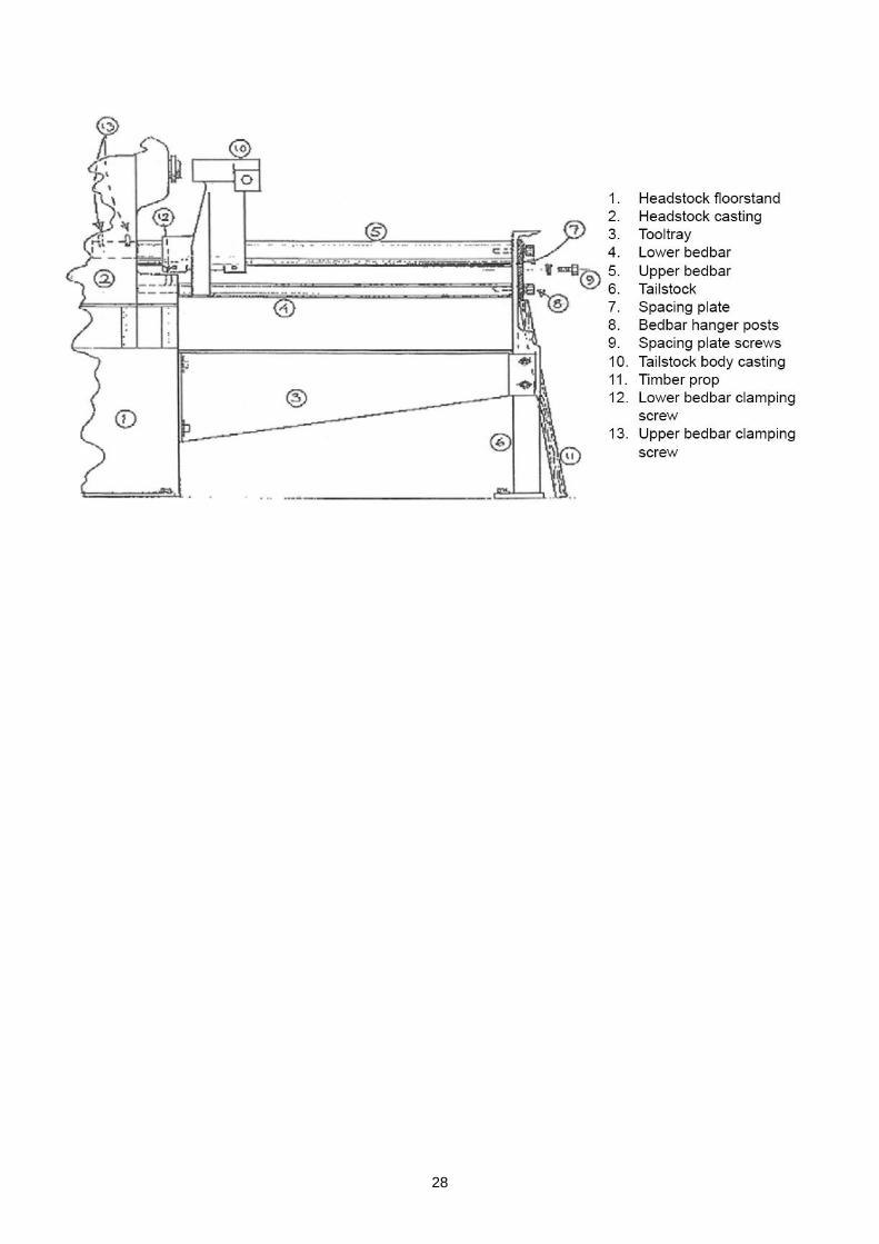
Basic assembly of the tailstock with its support members is outlined in section 2.1.4 Tailstock fixing earlier in this manual. After initial installation of the bed etc., it remains to align the tailcentre precisely with the drivecentre. Partially rotating the upper and lower bedbars will accomplish this. After initial assembly however, the weight of the bed and the tailstock casting will be mainly supported in the corresponding headstock bores making the bars very difficult to rotate. So that the bars can be turned easily, it is important that the assemblies’ weight is evenly supported at both ends. Proceed as follows: 1. Release the upper and lower bedbar clamping screws which normally prevent the bars from rotating in the headstock casting. These three screws are located in the headstock casting where the bars enter their respective bores - two screws (13) hold the upper bar and one screw (12) the lower bar. 2. Pivot the tailstock body casting (10) upright and slide it along the bed so that it is positioned close to the headstock. This minimises the leverage exerted in the bed locating bores. 3. Slacken the two M16 bed hanger bolts (8) which pass through the spacing plate (7) into the ends of the bedbars. Also slacken the two screws (9) which clamp the spacing plate to the tailstock leg. The whole weight of the assembly will now be hanging in the headstock bores. 4. Cut a timber prop to a length approximately 1” longer than the vertical distance between the lower edge of the spacing plate and the floor, as shown in the sketch below. The weight of the assembly’s outer end can nowbe progressively supportedby tapping the prop gently in at its bottom end. To determine when the optimum vertical force is being applied (not too much nor too little) simply try to rotate the upper bed bar with a tommy bar supporting the tailstock body casting by hand in a more or less upright position. When the weight of the assembly is evenly supported the bar will turn with relative ease.
5. Re-tighten the two screws which secure the spacing plate to the tailstock leg and remove the timber prop. Check that the upper bed bar can still be rotated without the need for excessive force. 6. To align the centres, proceed as follows (accurately inserting a pointed drive centre and tail centre into the headstock and tailstockmakes visually aligning the centres easier): a) First rotate the lower bedbar so that the tailcentre pivots downwards and to the left (as viewed from the outer end of the bed) to the fullest extent possible. b) Support the weight of the tailstock body with one hand and bring the tail centre as close as possible to the drive centre. Now pivot the tailstock on its mounting bar so that it describes a small arc close to the tip of the drivecentre. It will be seen that the tailstock body must be raised or lowered for the tailcentre to “kiss” the drivecentre at some point on its arc. c) Using a tommy bar in one of the holes provided near the outer end of the upper bedbar, rotate it in the required direction (clockwise to raise the assembly, anticlockwise to lower it) until the centres “kiss”. At this stage the upper bar can be loosely clamped to hold setting. d) Again, support the weight of the tailstock body but allow it to keep contact with the lower bedbar. As the lower bar is rotated, its eccentric action will progressively raise the tailcentre. Continue until the head and tailcentres are aligned. Loosely clamp the lower bedbar and recheck the alignment of the centres.e) Fully tighten all bed fixing screws etc. at both ends of the assembly.
28
29
2.7.2 TAILSTOCK BODY POSITIONING:
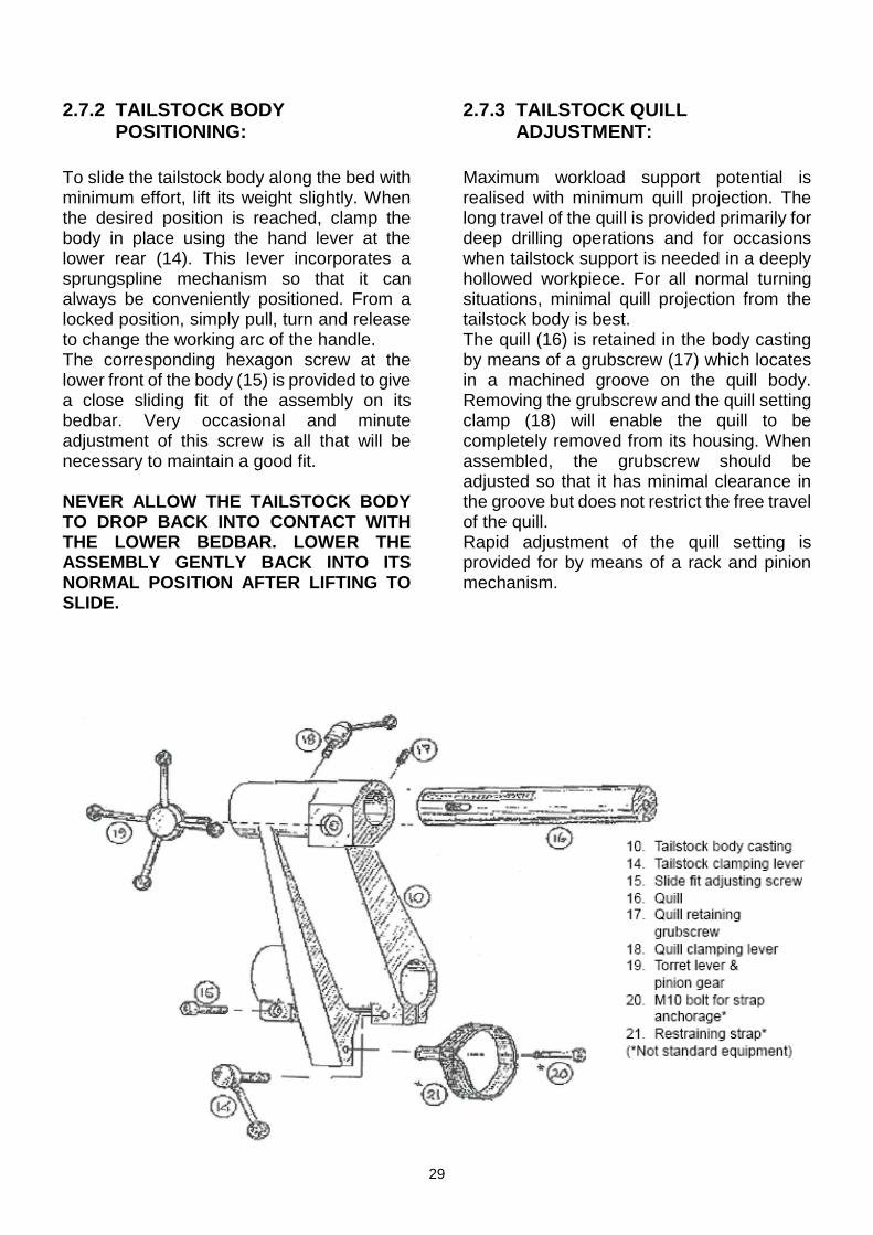
To slide the tailstock body along the bed with minimum effort, lift its weight slightly. When the desired position is reached, clamp the body in place using the hand lever at the lower rear (14). This lever incorporates a sprungspline mechanism so that it can always be conveniently positioned. From a locked position, simply pull, turn and release to change the working arc of the handle. The corresponding hexagon screw at the lower front of the body (15) is provided to give a close sliding fit of the assembly on its bedbar. Very occasional and minute adjustment of this screw is all that will be necessary to maintain a good fit. NEVER ALLOW THE TAILSTOCK BODY TO DROP BACK INTO CONTACT WITH THE LOWER BEDBAR. LOWER THE ASSEMBLY GENTLY BACK INTO ITS NORMAL POSITION AFTER LIFTING TO SLIDE.
2.7.3 TAILSTOCK QUILL ADJUSTMENT:
Maximum workload support potential is realised with minimum quill projection. The long travel of the quill is provided primarily for deep drilling operations and for occasions when tailstock support is needed in a deeply hollowed workpiece. For all normal turning situations, minimal quill projection from the tailstock body is best. The quill (16) is retained in the body casting by means of a grubscrew (17) which locates in a machined groove on the quill body. Removing the grubscrew and the quill setting clamp (18) will enable the quill to be completely removed from its housing. When assembled, the grubscrew should be adjusted so that it has minimal clearance in the groove but does not restrict the free travel of the quill. Rapid adjustment of the quill setting is provided for by means of a rack and pinion mechanism.

30
The four arm turret lever (19) with integral pinion is designed to be easily removable in situations where it might obstruct turning tool access. Simply “pull” to remove turret lever. The turret lever and rack and pinion drive on the tailstock quill is designed to permit quick and easy boring using the tailstock. However this mechanism makes it very easy to exert too much pressure when turning between centres. So as not to put undue pressure on the thrust washers and stall the machine, adjust centres by using just the centre boss of the capstain. ALWAYS DOUBLE CHECK THAT THE TAILCENTRE IS PROPERLY SEATED IN THE WORKPIECE AND THAT ALL ADJUSTABLE SETTINGS ARE FIRMLY CLAMPED IN THE REQUIRED POSITION BEFORE COMMENCING TURNING OR BORING OPERATIONS.
2.7.4 TAILCENTRE REMOVAL:
A 12mm wide slot is machined through the tailstock quill near its front end. To eject the centre being used, wind the quill forward so that the full length of the slot is visible. Insert a 12mm diameter tommy bar so that it projects through the shaft on both sides of the slot and wind the quill back into the tailstock body until the centre releases.
2.7.5 COMPLETE TAILSTOCK ASSEMBLY/ REMOVAL:
To turn diameters in excess of 26” the tailstock assembly must be removed. This can be done by reversing the assembly procedures described in section 2.1.4. If there is a frequent need to remove the tailstock, then it is worth buying (or making) a jig which can holt the positional relationship of the bedbars and tooltray when the fastenings at the headstock end of the tailstock assembly are undone. In this way the complete tailstock assembly, including the tooltray and leg, can be removed as a unit without disturbing the settings. When needed, the tailstock assembly can be relocated in a minimum of time.
REMEMBER THAT THE TAILSTOCK ASSEMBLY IS OF EXTREMELY HEAVY CONSTRUCTION. DO NOT ATTEMPT TO REMOVE IT AS AN ASSEMBLED UNIT FROM THE HEADSTOCK BEFORE ADEQUATE AND STABLE SUPPORT IS PROVIDED. THE BEDBARS ARE NOT DESIGNED TO BE SELFSUPPORTING WHEN FASTENED AT THE LEG END ALONE.
2.7.6 TAILSTOCK RESTRAINING STRAP:
If you wish to park the tailstock body out of the turning circle, it can be pivoted over to the right and gently lowered until it meets the restraint of the sub assembly. Alternatively, a restraining strap can be fitted (See illustration on previous page, points 20 & 21 – not supplied). The downwardly projecting portion of the tailstock body casting which rests against the lower bedbar has a hole tapped in its right-hand side. An M10 bolt with about 25mm (1”) of plain shank can be screwed into this hole. A webbing or nylon cord strap can now be stitched around the shank of the bolt to form a closed loop around the lower bedbar. The loop should be of sufficient length to allow the tailstock body to be parked at approximately 45° from vertical (or 13.30 hours).
2.7.7 DRILL DEPTH GUIDE:
A calibrated scale is set into the tailstock quill. Drill depth can be simply calculated as the difference between the starting and finishing figures as read from the point where the scale emerges from the tailstock body casting.
2.7.8 MAINTENANCE:
Use a few drops of VB-LUBE on bright metal and slide components to aid smooth operation. If the lathe is sited in areas of potentially high humidity, periodically wipe over bright metal parts with WD40 or a similar lubricant with anticorrosive properties.
31