Operators Manual TTN LUBRICATOR - Bijur Delimon · relief valve settings, ... subjected to stone...
13
Operators Manual TTN LUBRICATOR Series Progressive 35580 r#9
-
Upload
nguyendieu -
Category
Documents
-
view
253 -
download
2
Transcript of Operators Manual TTN LUBRICATOR - Bijur Delimon · relief valve settings, ... subjected to stone...
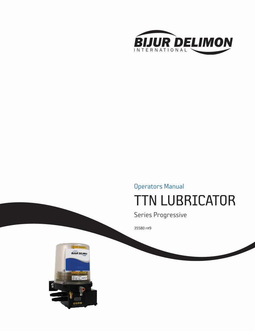
Operators Manual
TTN LUBRICATORSeries Progressive
35580 r#9
2 BIJUR DELIMON INTERNATIONAL OPERATORS MANUAL TTN LUBRICATOR 35580 r#9
© Copyright Bijur Delimon International 2008.
Bijur Delimon International reserves the right to
update or improve the technical specifications for this
product without prior notice.
BIJUR DELIMON INTERNATIONAL
(919) 465 4448 LOCAL (800) 631 0168 TOLL-FREE (919) 465 0516 FAX
WWW.BIJURDELIMON.COM
2100 Gateway Centre Blvd., Suite 109 Morrisville, NC 27560
Contents
Precautions & Symbols .................................2
Manufacturer’s Statement ...........................2
General ............................................................2
Application ......................................................2
TTN Lubricator at a Glance ...........................3
Technical Data ................................................4
ISO Schematic ................................................4
Wiring ...............................................................5
Safety ...............................................................6
Installation .....................................................6
Lubricator Operation ....................................7
Controller Operation* ...................................7
Controller Modes .......................................8-9
Maintenance................................................. 10
Troubleshooting .......................................... 10
How to Order ................................................ 10
Dimensional Schematics ............................ 12
Precautions & Symbols
The following symbols, used to identify safety instructions, are defined as follows:
Non-compliance will affect safety.
Electrical safety is involved.
Safe operation of the lubricator and/ or protection of the lubricator should be considered.
Electrical connections made to Earth ground.
Conditions and actions that pose hazards to the user.
NElectrical connections made to the neutral conductor are identified with the capital “N”
All safety and/or warning labels affixed to the TTN Progressive Series Lubricators must be maintained in a completely legible condition. Also, any modifications made to the TTN Progressive Series Lubricators (or to any of its components) must be approved by Bijur Delimon International prior to its use; otherwise the warranty and any liability by Bijur Delimon Interna-tional will be null and void.
Manufacturer’s StatementThe manufacturer and/or distributor has provided the parts list and assembly diagram in this manual as a reference tool only. Neither the manufacturer or distribu-tor makes any representation or warranty of any kind to the buyer that he or she is qualified to make any repairs or replace any parts to the product. In fact, the manufacturer and/or distributor expressly states that all repairs and parts replace-ments should be undertaken by certified and licensed technicians, and not by the buyer. The buyer assumes all risk and liability arising out of his or her repairs to the original product or replacement parts thereto, or arising out of his or her installation of replacement parts thereto.
GeneralTTN Lubricators are electrically driven piston pumps designed for use with series progressive systems. For injector systems refer to Datasheet #35547. These lubricators can be fitted with up to three independent piston elements providing positive displacement output to series progressive divider valves. TTN Lubricators are available with an integral program-mable controller, low level switch and various reservoir capacities. Operating voltages are either 12 or 24 VDC.
Before installing this lubricator, please read this Operators Manual carefully. Failure to follow these instructions can result in damage to the product and/or serious bodily injury. The TTN Progressive Series Lubricator meets all of the operat-ing parameters for Bijur Delimon series progressive centralized lubricating systems. You will need this manual for the safety warnings and precautions, assembly, operating, inspection, maintenance and cleaning procedures, parts list and assembly diagram. Keep your invoice with this manual. Write the invoice number on the inside of the front cover. Keep this manual and invoice in a safe and dry place for future reference.
ApplicationTTN Lubricators are ideally suitable for off road mobile machinery such as loaders, excavators, articulated trucks, graders, etc. These lubricators are designed to work in conditions found in the construction, mining and forestry industries. A unique reservoir design keeps out contamination and prevents condensation from forming, thus assuring reliable automatic lubrica-tion of critical wear points such as bearings, bushings and pins.
3BIJUR DELIMON INTERNATIONAL OPERATORS MANUAL TTN LUBRICATOR 35580 r#9
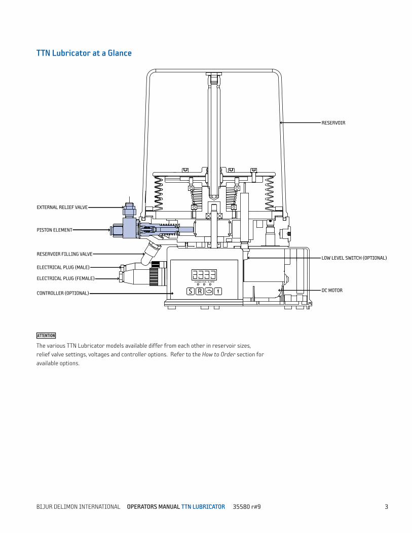
TTN Lubricator at a Glance
The various TTN Lubricator models available differ from each other in reservoir sizes, relief valve settings, voltages and controller options. Refer to the How to Order section for available options.
ELECTRICAL PLUG (MALE)
RESERVOIR FILLING VALVE
PISTON ELEMENT
EXTERNAL RELIEF VALVE
ELECTRICAL PLUG (FEMALE)
CONTROLLER (OPTIONAL)
RESERVOIR
LOW LEVEL SWITCH (OPTIONAL)
DC MOTOR
RUNPOWER ALARM
S R
4 BIJUR DELIMON INTERNATIONAL OPERATORS MANUAL TTN LUBRICATOR 35580 r#9
1 Grease used in system must be pumpable at the temperatures referenced. Contact lubricant manufacturer with specific questions.
2 Electrical Connections Specifications
Number of contacts: 3+PE Wire gauge: AWG 20-14 Cable diameter: 6-9.5mm Screw termination IP Enclosure Rating: IP-67
3 European version is 1/4” BSPP. See notes on page 9.
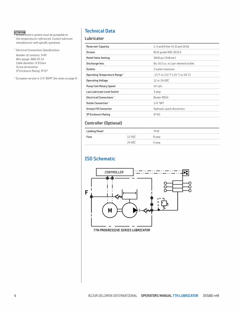
Technical DataLubricator
Reservoir Capacity 2, 4 and 8 liter (4, 8 and 16 lb)
Grease NLGI grade 000, 00 & 0
Relief Valve Setting 3600 psi (248 bar)
Discharge/min. 8cc (0.5 cu. in.) per element/outlet
Outlets 3 outlet maximum
Operating Temperature Range 1 -13˚F to 122˚F (-25˚C to 50˚C)
Operating Voltage 12 or 24 VDC
Pump Cam Rotary Speed 42 rpm
Low Lubricant Level Switch 3 amp
Electrical Connections 2 Binder RD24
Outlet Connection 3 1/4” NPT
Grease Fill Connector Hydraulic quick disconnect
IP Enclosure Rating IP-65
Controller (Optional)
Loading Power 70 W
Fuse 12 VDC 8 amp
24 VDC 5 amp
ISO Schematic
3M
CONTROLLER
F
TTN PROGRESSIVE SERIES LUBRICATOR
5BIJUR DELIMON INTERNATIONAL OPERATORS MANUAL TTN LUBRICATOR 35580 r#9
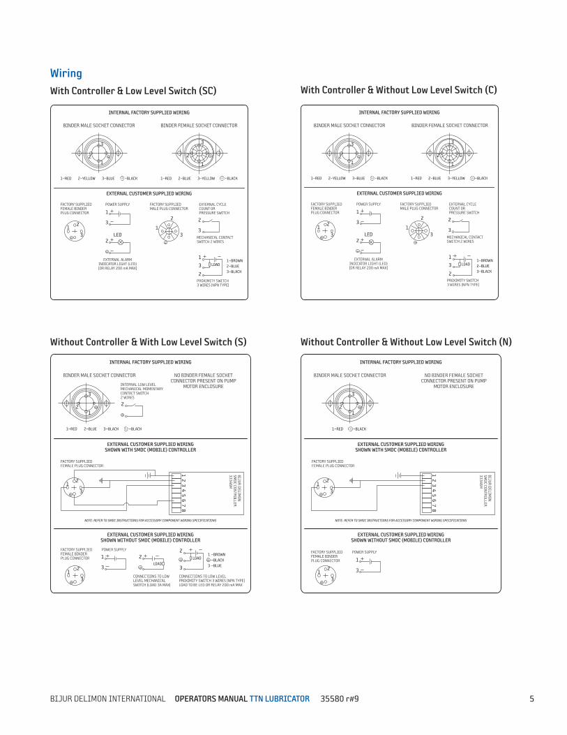
WiringWith Controller & Low Level Switch (SC)
Without Controller & With Low Level Switch (S)
With Controller & Without Low Level Switch (C)
Without Controller & Without Low Level Switch (N)
LOAD
3
21
12
3
3
2
1
BINDER MALE SOCKET CONNECTOR
INTERNAL FACTORY SUPPLIED WIRING
EXTERNAL CUSTOMER SUPPLIED WIRING
BINDER FEMALE SOCKET CONNECTOR
FACTORY SUPPLIED FEMALE BINDER PLUG CONNECTOR
1—RED 2—YELLOW 3—BLUE —BLACK 1—RED 2—BLUE 3—YELLOW —BLACK
2
3MECHANICAL CONTACT SWITCH 2 WIRES
EXTERNAL CYCLE COUNT OR PRESSURE SWITCH
POWER SUPPLY
LED
1
3
2
EXTERNAL ALARM INDICATOR LIGHT (LED) [OR RELAY 200 mA MAX]
1
2
3
FACTORY SUPPLIED MALE PLUG CONNECTOR
3
1
2PROXIMITY SWITCH3 WIRES |NPN TYPE|
1—BROWN 2—BLUE 3—BLACK
3
21
BINDER MALE SOCKET CONNECTOR
INTERNAL FACTORY SUPPLIED WIRING
EXTERNAL CUSTOMER SUPPLIED WIRINGSHOWN WITH SMDC (MOBILE) CONTROLLER
1—RED —BLACK
NO BINDER FEMALE SOCKET CONNECTOR PRESENT ON PUMP
MOTOR ENCLOSURE
12
3
NOTE: REFER TO SMDC INSTRUCTIONS FOR ACCESSORY COMPONENT WIRING SPECIFICATIONS
FACTORY SUPPLIED FEMALE PLUG CONNECTOR
BIJUR DELIMON
SM
DC CONTROLLER
33346M
EXTERNAL CUSTOMER SUPPLIED WIRINGSHOWN WITHOUT SMDC (MOBILE) CONTROLLER
1 2
3 4
5 6
7 8
POWER SUPPLY
12
3
1
3
FACTORY SUPPLIED FEMALE BINDER PLUG CONNECTOR
3
21
12
3
BINDER MALE SOCKET CONNECTOR
INTERNAL FACTORY SUPPLIED WIRING
EXTERNAL CUSTOMER SUPPLIED WIRINGSHOWN WITH SMDC (MOBILE) CONTROLLER
NOTE: REFER TO SMDC INSTRUCTIONS FOR ACCESSORY COMPONENT WIRING SPECIFICATIONS
FACTORY SUPPLIED FEMALE PLUG CONNECTOR
BIJUR DELIMON
SM
DC CONTROLLER
33346M
EXTERNAL CUSTOMER SUPPLIED WIRINGSHOWN WITHOUT SMDC (MOBILE) CONTROLLER
NO BINDER FEMALE SOCKET CONNECTOR PRESENT ON PUMP
MOTOR ENCLOSURE1
2 3
4 5
6 7
8
1—RED 2—BLUE 3—BLACK —BLACK
2
INTERNAL LOW LEVEL MECHANICAL MOMENTARY CONTACT SWITCH2 WIRES
POWER SUPPLY
12
3
1
3
CONNECTIONS TO LOW LEVEL PROXIMITY SWITCH 3 WIRES |NPN TYPE|LOAD TO BE LED OR RELAY 200 mA MAX
CONNECTIONS TO LOW LEVEL MECHANICAL SWITCH |LOAD 3A MAX|
FACTORY SUPPLIED FEMALE BINDER PLUG CONNECTOR
2
3
LOAD2LOAD
1
3
—BROWN —BLACK —BLUE
3
21
POWER SUPPLY
12
3 LED
1
3
2
2
3
3
1
2
3
2
1
1
2
3
BINDER MALE SOCKET CONNECTOR
INTERNAL FACTORY SUPPLIED WIRING
EXTERNAL CUSTOMER SUPPLIED WIRING
BINDER FEMALE SOCKET CONNECTOR
MECHANICAL CONTACT SWITCH 2 WIRES
EXTERNAL CYCLE COUNT OR PRESSURE SWITCH
PROXIMITY SWITCH3 WIRES |NPN TYPE|
EXTERNAL ALARM INDICATOR LIGHT (LED) [OR RELAY 200 mA MAX]
FACTORY SUPPLIED FEMALE BINDER PLUG CONNECTOR
FACTORY SUPPLIED MALE PLUG CONNECTOR
1—RED 2—YELLOW 3—BLUE —BLACK 1—RED 2—BLUE 3—YELLOW —BLACK
1—BROWN 2—BLUE 3—BLACK
LOAD
6 BIJUR DELIMON INTERNATIONAL OPERATORS MANUAL TTN LUBRICATOR 35580 r#9
SafetyThis Operators Manual covers fundamental concepts, which are to be observed for installation, operation and maintenance. Therefore, it is absolutely necessary that the Operators Manual be studied by the person doing the installation prior to installation and start-up. It is also necessary to have this Operators Manual nearby and available for reference in the future. The safety instructions mentioned in this Operators Manual, as well as all national operating and safety regulations for the safe operation of such equipment are to be observed.
Installation
Before beginning the installation work, disconnect the electrical supply. Do not remove or modify any safety equipment currently installed on a construction machine or commercial vehicle. If neces-sary, this equipment can be temporarily removed during the installation of the TTN Lubricator.
1. Locate the TTN Lubricator away from heat sources.
2. Provide access to the lubricator for means of filling, cleaning and visual inspection.
3. Always adhere to installation instruc-tions of the machine or vehicle manufacturer with regards to drilling and welding procedures. Observe minimum distances specified between holes and the upper and lower flange of the frame or between the holes.
4. Use drilling templates to locate and drill mounting holes. Mounting plates and templates are available for this product. When possible use existing mounting holes or studs.
5. Lubrication lines and electrical cable must be secured by means of clamps or straps to prevent them from rubbing or coming loose. Keep lines away from shocks, heat and areas subjected to stone and debris impact. For added protection lines or cables should be wrapped with appropriate loom or spiral wrap.
Reservoir Filling
Follow proper filling procedures:
+ Use only approved lubricant; grease must be pumpable at the temperatures your equipment is subjected to.
+ Use only new and clean lubricant and clean filling devices; dirt and other forms of contamination are a leading cause of pump failure.
+ Use of either a manual or an automatic filling device is appropriate; care should be taken to avoid developing high grease pressure inside the bellows during the filling process. Overfilling the reservoir can lead to pump damage and risk of injury.
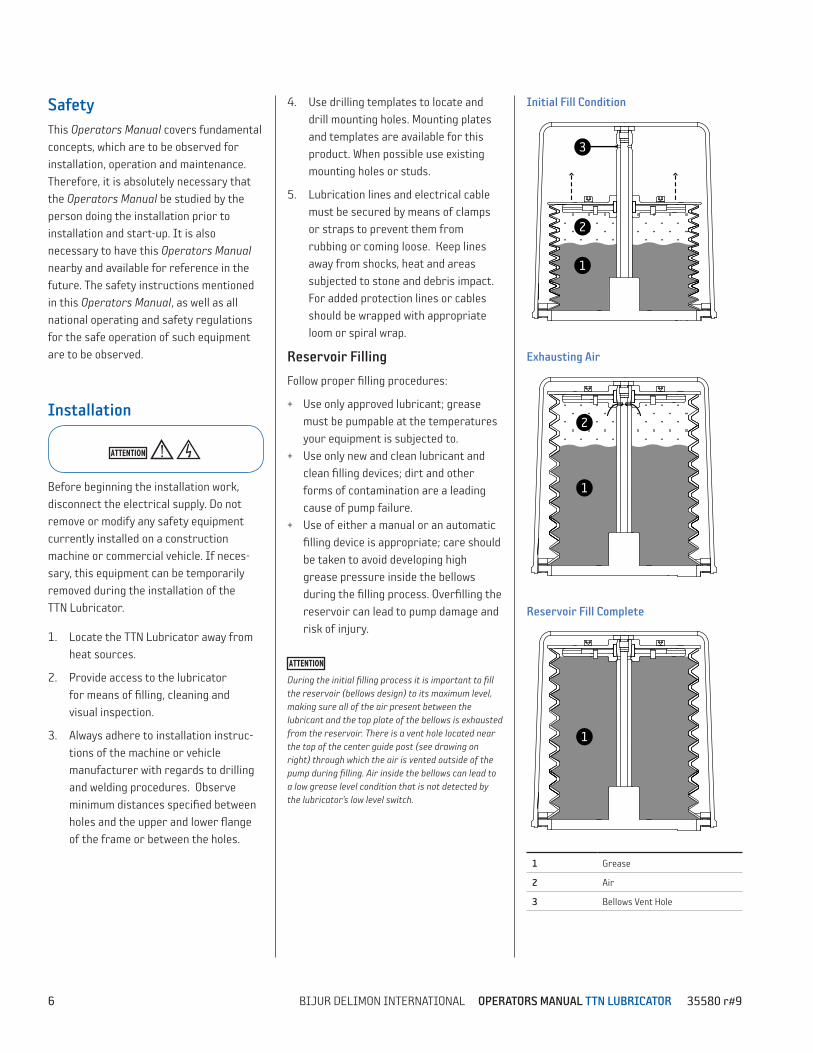
During the initial filling process it is important to fill the reservoir (bellows design) to its maximum level, making sure all of the air present between the lubricant and the top plate of the bellows is exhausted from the reservoir. There is a vent hole located near the top of the center guide post (see drawing on right) through which the air is vented outside of the pump during filling. Air inside the bellows can lead to a low grease level condition that is not detected by the lubricator’s low level switch.
Initial Fill Condition
Exhausting Air
Reservoir Fill Complete
1 Grease
2 Air
3 Bellows Vent Hole
1
2
3
1
2
1
1
2
3
1
2
1
1
2
3
1
2
1
7BIJUR DELIMON INTERNATIONAL OPERATORS MANUAL TTN LUBRICATOR 35580 r#9
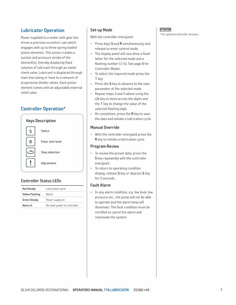
Keys Description
S Select
R Enter and reset
Step selection
Adjustment
Lubricator OperationPower supplied to a motor with gear box drives a precision eccentric cam which engages with up to three spring loaded piston elements. This action creates a suction and pressure stroke of the element(s), thereby displacing fixed volumes of lubricant through an outlet check valve. Lubricant is displaced through main line tubing or hose to a network of progressive divider valves. Each piston element comes with an adjustable external relief valve.
Controller Operation*
Controller Status LEDs
Red Steady Lubrication cycle
Yellow Flashing Alarm
Green Steady Power supply on
None Lit No input power to controller
Set-up Mode
With the controller energized:
+ Press keys S and R simultaneously and release to enter control mode.
+ The display panel will now show a fixed letter for the selected mode and a flashing number (1-4). See page 8 for Controller Modes.
+ To select the required mode press the key.
+ Press the S key to advance to the next parameter of the selected mode.
+ Repeat steps 3 and 4 above using the key to move across the digits and
the key to change the value of the selected flashing digit.
+ On completion, press the R key to save the data and initiate a lubrication cycle.
Manual Override
+ With the controller energized press the R key to initiate a lubrication cycle.
Program Review
+ To review the preset data, press the S key repeatedly with the controller energized.
+ To return to operating condition display, release S key or depress S key for 5 seconds.
Fault Alarm
+ In any alarm condition, e.g. low level, low pressure etc., the pump will not be able to operate and the alarm lamp will illuminate. The fault condition must be rectified to cancel the alarm and reactivate the system.
* For optional controller versions.
8 BIJUR DELIMON INTERNATIONAL OPERATORS MANUAL TTN LUBRICATOR 35580 r#9
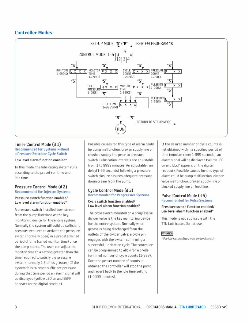
SET-UP MODE “S”+”R”
CONTROL MODE 1~41 2 3 4
RUN TIME1~999(S)
MONITORTIME1~999(S)
IDLE TIME 1~9999(M)
RETURN TO SET UP MODE
RUN
CYCLE COUNT1~999(C)
PRESSURE COUNT1~99(C)
PULSE ON1~99(S)
PULSE OFF1~99(S)
REVIEW PROGRAM ”S”
“S”
“S” “S”
“S” “S” “S”
“S”
“S”
“S”
“S”
“S”“R”
X
X X X X X X X X X X X
X X
X X
X X X X
“S”
HOLD PRESSURE1~99(S)
X X X MONITORTIME1~999(S)
X X X
“S”
Possible causes for this type of alarm could be pump malfunction, broken supply line or crushed supply line prior to pressure switch. Lubrication intervals are adjustable from 1 to 9999 minutes. An adjustable run delay(1-99 seconds) following a pressure switch closure assures adequate pressure downstream from the pump.
Cycle Control Mode (d 3)Recommended for Progressive Systems
Cycle switch function enabled/ Low level alarm function enabled*
The cycle switch mounted on a progressive divider valve is the key monitoring device for the entire system. Normally when grease is being discharged from the outlets of the divider valve, a cycle pin engages with the switch, confirming a successful lubrication cycle. The controller can be programmed to allow for a prede-termined number of cycle counts (1-999). Once the preset number of counts is obtained the controller will stop the pump and revert back to the idle time setting (1-9999 minutes).
If the desired number of cycle counts is not obtained within a specified period of time (monitor time: 1-999 seconds), an alarm signal will be displayed (yellow LED on and EEcY appears on the digital readout). Possible causes for this type of alarm could be pump malfunction, divider valve malfunction, broken supply line or blocked supply line or feed line.
Pulse Control Mode (d 4)Recommended for Pulse Systems
Pressure switch function enabled/ Low level alarm function enabled*
This mode is not applicable with the TTN Lubricator. Do not use.
* For lubricators fitted with low level switch
Controller Modes
Timer Control Mode (d 1)Recommended for Systems without a Pressure Switch or Cycle Switch
Low level alarm function enabled*
In this mode, the lubricating system runs according to the preset run time and idle time.
Pressure Control Mode (d 2)Recommended for Injector Systems
Pressure switch function enabled/ Low level alarm function enabled*
A pressure switch installed downstream from the pump functions as the key monitoring device for the entire system. Normally the system will build up sufficient pressure required to activate the pressure switch (normally open) in a predetermined period of time (called monitor time) once the pump starts. The user can adjust the monitor time to a setting greater than the time required to satisfy the pressure switch (normally 1.5 times greater). If the system fails to reach sufficient pressure during that time period an alarm signal will be displayed (yellow LED on and EEPP appears on the digital readout).
9BIJUR DELIMON INTERNATIONAL OPERATORS MANUAL TTN LUBRICATOR 35580 r#9
Controller Mode Cont.
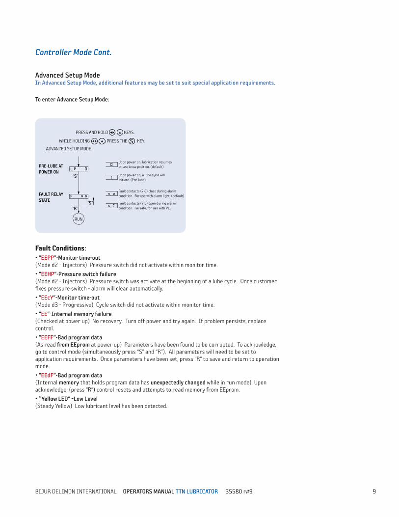
Advanced Setup ModeIn Advanced Setup Mode, additional features may be set to suit special application requirements.
To enter Advance Setup Mode:
Fault Conditions:• ”EEPP”-Monitor time-out (Mode d2 - Injectors) Pressure switch did not activate within monitor time.
• ”EEHP”-Pressure switch failure (Mode d2 - Injectors) Pressure switch was activate at the beginning of a lube cycle. Once customer fixes pressure switch - alarm will clear automatically.
• ”EEcY”-Monitor time-out (Mode d3 - Progressive) Cycle switch did not activate within monitor time.
• ”EE”-Internal memory failure (Checked at power up) No recovery. Turn off power and try again. If problem persists, replace control.
• ”EEFF”-Bad program data (As read from EEprom at power up) Parameters have been found to be corrupted. To acknowledge, go to control mode (simultaneously press “S” and “R”). All parameters will need to be set to application requirements. Once parameters have been set, press “R” to save and return to operation mode.
• ”EEdF”-Bad program data (Internal memory that holds program data has unexpectedly changed while in run mode) Upon acknowledge, (press “R”) control resets and attempts to read memory from EEprom.
• “Yellow LED” -Low Level (Steady Yellow) Low lubricant level has been detected.
PRESS AND HOLD KEYS.
S
WHILE HOLDING , PRESS THE KEY.
ADVANCED SETUP MODE
PRE-LUBE ATPOWER ON
FAULT RELAYSTATE
Upon power on, lubrication resumesat last know position. (default)
Upon power on, a lube cycle willinitiate. (Pre-lube)
Fault contacts (7,8) close during alarmcondition. For use with alarm light. (default)
Fault contacts (7,8) open during alarmcondition. Failsafe, for use with PLC.
“S”
“R”
RUN
“S”
10 BIJUR DELIMON INTERNATIONAL OPERATORS MANUAL TTN LUBRICATOR 35580 r#9
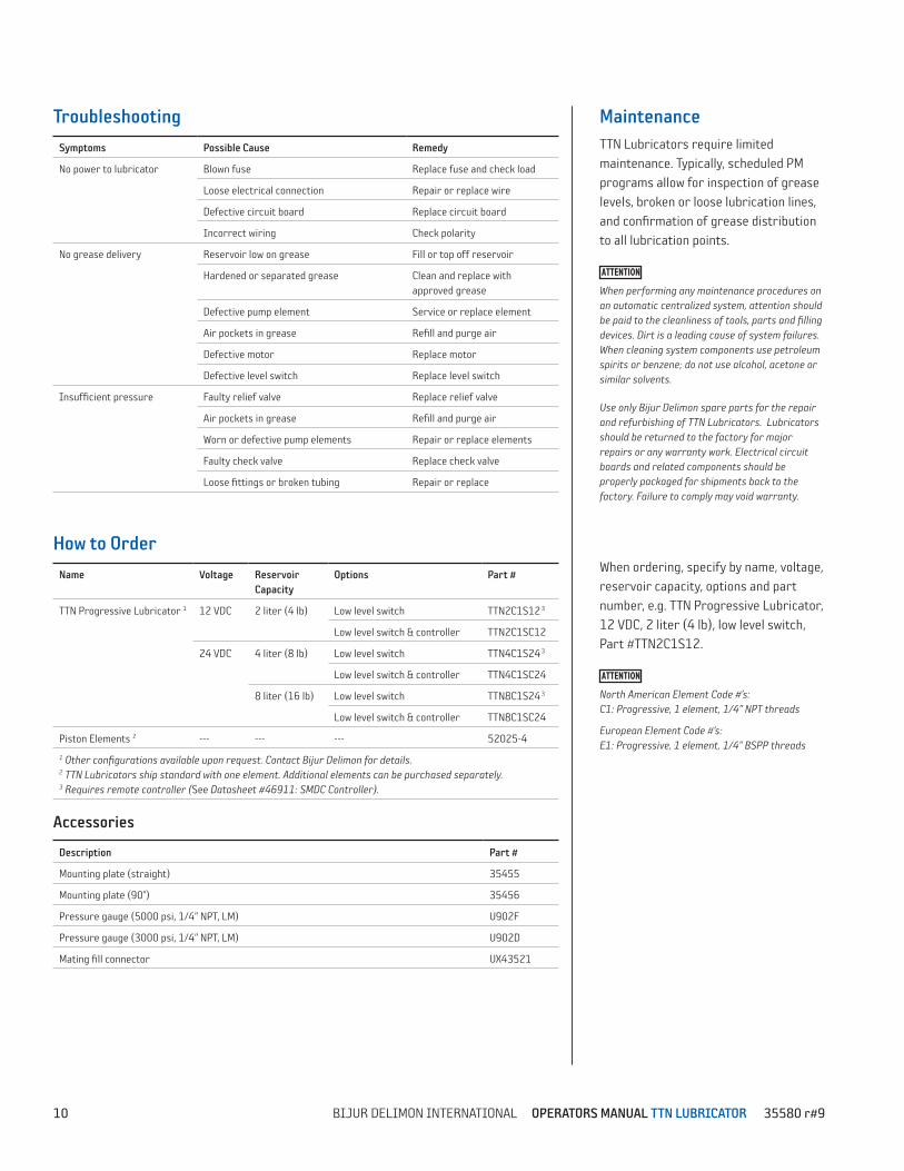
MaintenanceTTN Lubricators require limited maintenance. Typically, scheduled PM programs allow for inspection of grease levels, broken or loose lubrication lines, and confirmation of grease distribution to all lubrication points.
When performing any maintenance procedures on an automatic centralized system, attention should be paid to the cleanliness of tools, parts and filling devices. Dirt is a leading cause of system failures. When cleaning system components use petroleum spirits or benzene; do not use alcohol, acetone or similar solvents.
Use only Bijur Delimon spare parts for the repair and refurbishing of TTN Lubricators. Lubricators should be returned to the factory for major repairs or any warranty work. Electrical circuit boards and related components should be properly packaged for shipments back to the factory. Failure to comply may void warranty.
Troubleshooting
Symptoms Possible Cause Remedy
No power to lubricator Blown fuse Replace fuse and check load
Loose electrical connection Repair or replace wire
Defective circuit board Replace circuit board
Incorrect wiring Check polarity
No grease delivery Reservoir low on grease Fill or top off reservoir
Hardened or separated grease Clean and replace with approved grease
Defective pump element Service or replace element
Air pockets in grease Refill and purge air
Defective motor Replace motor
Defective level switch Replace level switch
Insufficient pressure Faulty relief valve Replace relief valve
Air pockets in grease Refill and purge air
Worn or defective pump elements Repair or replace elements
Faulty check valve Replace check valve
Loose fittings or broken tubing Repair or replace
How to Order
Name Voltage Reservoir Capacity
Options Part #
TTN Progressive Lubricator 1 12 VDC 2 liter (4 lb) Low level switch TTN2C1S123
Low level switch & controller TTN2C1SC12
24 VDC 4 liter (8 lb) Low level switch TTN4C1S243
Low level switch & controller TTN4C1SC24
8 liter (16 lb) Low level switch TTN8C1S243
Low level switch & controller TTN8C1SC24
Piston Elements 2 --- --- --- 52025-4
1 Other configurations available upon request. Contact Bijur Delimon for details. 2 TTN Lubricators ship standard with one element. Additional elements can be purchased separately.3 Requires remote controller (See Datasheet #46911: SMDC Controller).
Accessories
Description Part #
Mounting plate (straight) 35455
Mounting plate (90°) 35456
Pressure gauge (5000 psi, 1/4” NPT, LM) U902F
Pressure gauge (3000 psi, 1/4” NPT, LM) U902D
Mating fill connector UX43521
When ordering, specify by name, voltage, reservoir capacity, options and part number, e.g. TTN Progressive Lubricator, 12 VDC, 2 liter (4 lb), low level switch, Part #TTN2C1S12.
North American Element Code #’s: C1: Progressive, 1 element, 1/4” NPT threads
European Element Code #’s: E1: Progressive, 1 element, 1/4” BSPP threads
11BIJUR DELIMON INTERNATIONAL OPERATORS MANUAL TTN LUBRICATOR 35580 r#9
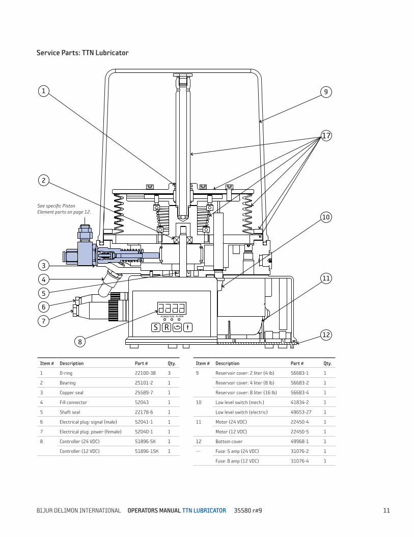
Service Parts: TTN Lubricator
RUNPOWER ALARM
S R7
8
11
12
10
9
6
5
4
3
2
1
17
Item # Description Part # Qty.
1 O-ring 22100-38 3
2 Bearing 25101-2 1
3 Copper seal 25589-7 1
4 Fill connector 52043 1
5 Shaft seal 22178-6 1
6 Electrical plug: signal (male) 52041-1 1
7 Electrical plug: power (female) 52040-1 1
8 Controller (24 VDC) 51896-SK 1
Controller (12 VDC) 51896-1SK 1
Item # Description Part # Qty.
9 Reservoir cover: 2 liter (4 lb) 56683-1 1
Reservoir cover: 4 liter (8 lb) 56683-2 1
Reservoir cover: 8 liter (16 lb) 56683-4 1
10 Low level switch (mech.) 41834-2 1
Low level switch (electric) 49653-27 1
11 Motor (24 VDC) 22450-4 1
Motor (12 VDC) 22450-5 1
12 Bottom cover 49968-1 1
--- Fuse: 5 amp (24 VDC) 31076-2 1
Fuse: 8 amp (12 VDC) 31076-4 1
See specific Piston Element parts on page 12.
12 BIJUR DELIMON INTERNATIONAL OPERATORS MANUAL TTN LUBRICATOR 35580 r#9
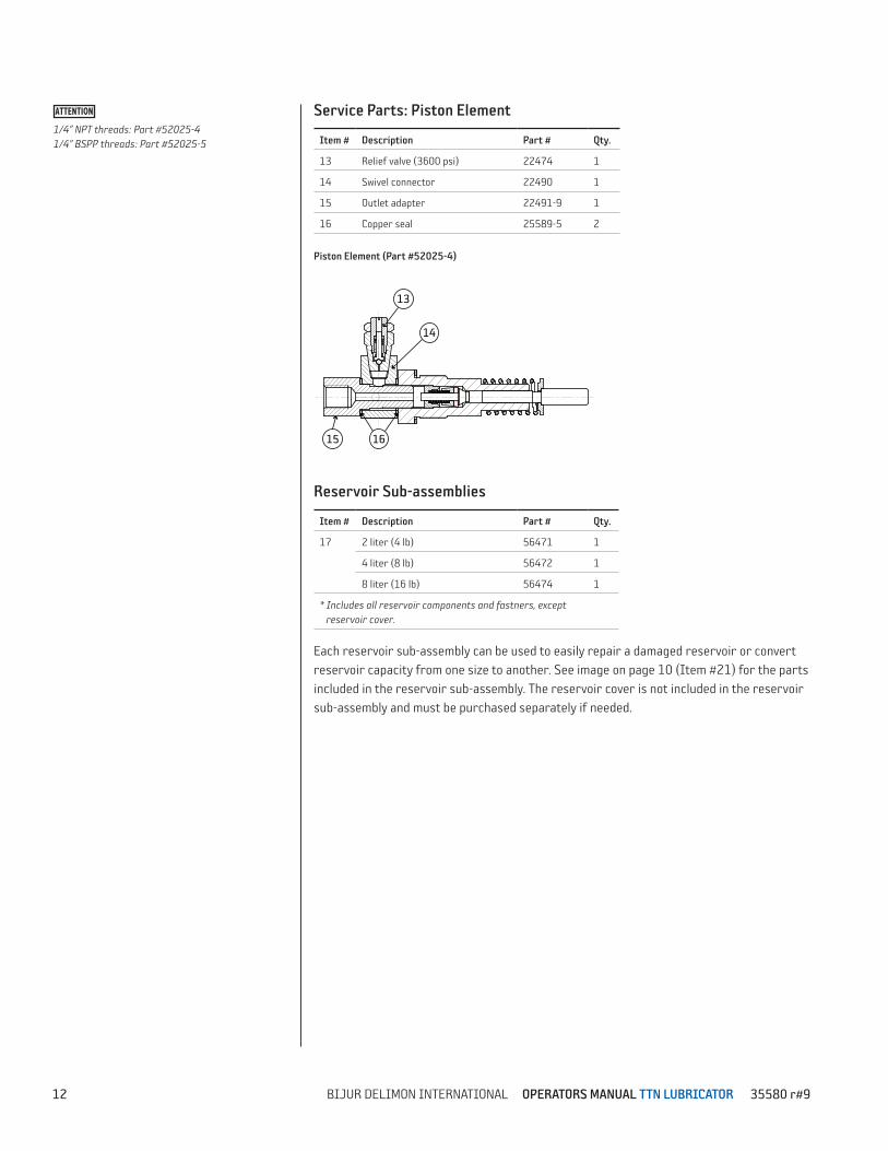
Service Parts: Piston Element
Item # Description Part # Qty.
13 Relief valve (3600 psi) 22474 1
14 Swivel connector 22490 1
15 Outlet adapter 22491-9 1
16 Copper seal 25589-5 2
Piston Element (Part #52025-4)
Reservoir Sub-assemblies
Item # Description Part # Qty.
17 2 liter (4 lb) 56471 1
4 liter (8 lb) 56472 1
8 liter (16 lb) 56474 1
* Includes all reservoir components and fastners, except reservoir cover.
Each reservoir sub-assembly can be used to easily repair a damaged reservoir or convert reservoir capacity from one size to another. See image on page 10 (Item #21) for the parts included in the reservoir sub-assembly. The reservoir cover is not included in the reservoir sub-assembly and must be purchased separately if needed.
14
13
15 16
1/4” NPT threads: Part #52025-4 1/4” BSPP threads: Part #52025-5
13BIJUR DELIMON INTERNATIONAL OPERATORS MANUAL TTN LUBRICATOR 35580 r#9
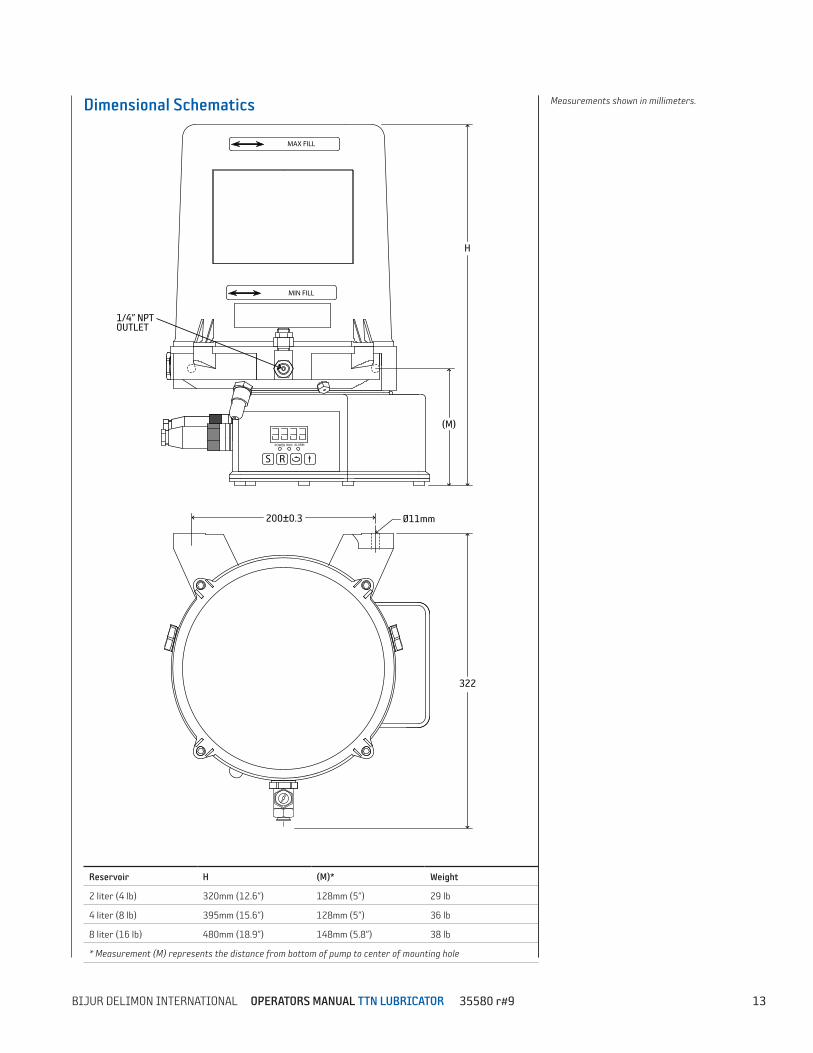
Dimensional Schematics
Reservoir H (M)* Weight
2 liter (4 lb) 320mm (12.6”) 128mm (5”) 29 lb
4 liter (8 lb) 395mm (15.6”) 128mm (5”) 36 lb
8 liter (16 lb) 480mm (18.9”) 148mm (5.8”) 38 lb
* Measurement (M) represents the distance from bottom of pump to center of mounting hole
Measurements shown in millimeters.
S R
RUNPOWER ALARM
322
H
(M)
200±0.3 Ø11mm
MAX FILL
MIN FILL
1/4” NPTOUTLET