Operators Manual DUALINE - Bijur Delimon · WARNING: All CS1000 and CS2000 grease reservoirs are...
12
Operators Manual DUALINE INSTALLATION & SYSTEM START-UP DL300 r#3
Transcript of Operators Manual DUALINE - Bijur Delimon · WARNING: All CS1000 and CS2000 grease reservoirs are...

Operators Manual
DUALINEINSTALLATION & SYSTEM START-UP
DL300 r#3

Farval®series - DUALINE SYSTEMS
2
CONTENTS & INSTALLATION
Contents
Installation .................................................2-3
Filling System..................................................4
Start-Up ...........................................................5
Service Instructions-Maintenance .............6
Troubleshooting .........................................7-8
SYSTEM INSTALLATION AND START UP(For Dualine Automatic Electric Powered and Air Powered Systems)
First study the schematic layout, the bearing list, and the applicable Bijur Delimon publications describing dualine sys-tems. Together they completely describe the system and its component assemblies. They also explain how the system and its component assemblies operate and how the various sub-assemblies-the pump, the reservoir, valve manifolds, and controls should be combined. In addition to becoming well acquainted with the lubricating system, it is often helpful to sketch the location of all manifolds and lube lines on the machine with chalk or crayon.
INSTALLATION
Pump Reservoir Assembly-Locate where it is protected from dirt and where it can be easily maintained and filled with lubricant. Bolt to a solid foundation (except air powered barrel pumps).
Measuring Valves-Mount on a flat surface close to the bearings (within 10 feet) and close to the machine for protec-tion but where accessible for adjusting and servicing. Valves may be mounted in any position but indicator stems should be visible and should face the same direction for easier checking. Mount with indicator stems down if excessive dirt and scale are present or order the proper U1732 series indicator covers.
Adjacent valve blocks may be piped together before mounting, using one union in each pipe connection between valves. Any welding of valve support brackets to the machine should be done before mounting valves.
Supply Lines-Clean inside of all pipe, not meeting Bulletin 1800 pipe specifications, as follows: (a) if un-pickled black pipe- shot or sandblasting, solvents, or a tube de-scaler (b) if galvanized pipe-drifting or sandblasting. Remove scale and spatter from pipe welds by thoroughly pounding, tapping, and blowing out with air. Remove chips produced by threading pipe before connections are made.
Pre-fill measuring valve to bearing discharge lines of grease systems with clean grease. It saves startup time and pre-vents overfilling of short discharge lines while waiting for long discharge lines to fill. Use hand pump, grease gun, or power pump. Fill entire coil of copper tubing with grease before cutting and installing.
Keep lines short. Place close to machine for protection and cover with a protective shield in hazardous locations. Clamp rigidly. Connect each supply line to the same port on each measuring valve (see Figures. 1 and 2) so that indicator stems will move in the same direction, making erratic performance more obvious. Do not connect discharge lines to bearings until later (see page 4 under “Bearings”).
Bleeder Valves-Install at high points to purge system of air.
Line Strainers and Line Checks-Install as shown in Figure 1.

Farval®series - DUALINE SYSTEMS
3
INSTALLATION
Pressure Control Switches (End-of-Line Systems with FR Reversing Valves)-Can locate anywhere in the line. If there ismore than one set of main supply lines, install switches in the set with greatest pressure drop (usually the longest) and in others with pressure drops of similar magnitude. See Figure 2.
Pressure Gauges (End-of-Line Systems with DR Reversing Valves)-Add pressure gauge U902F (0-5000 psi) where dis-tribution line ends at last measuring valve to help adjust system pressure during start up period.
Electric Wiring-Connect motor so that pump rotates as shown in the detail section. If there is more than one set of main supply lines with pressure control switches, wire the corresponding switches in each main line in series so that full line pressure develops throughout system before pump stops. See appropriate controller
CENTRALSTATION
V-1 V-2 V-3
MAIN SUPPLY LINES
MEASURING VALVE
PRESSURE SWITCHES U620D1 OR U6636OPERATE SOLENOID REVERSING VALVE& STOP PUMP WHEN MAXINUM PRESSUREIS REACHED.
PRESSURE GAUGESU902F HELP SETMAXINUM SYSTEM PRESSURE.
Figure 2 -DC41 System showing use of pressure switches.
Figure 1 - A typical automatic loop system.
RETURN LINES
MAIN SUPPLY LINES
RESERVOIR
PUMP
INSERT PLUGS AFTER SYSTEM HASBEEN FILLED WITH LUBRICANT,PURGED OF AIR AND READY FOROPERATION-SEE “FILLING SYSTEMWITH LUBRICANT"
ADD LINE STRAINERS TO RETURNLINES OF SYSTEMS WITH COMPLETE LOOPSAND TO DISCHARGE LINES OF END-OF-LINESYSTEMS THEY REMOVE FOREIGN MATTERWHICH MAY BE ADDED DURING INSTALLATION.
REVERSING VALVE OF SOMECS2000 & DC42 STATIONSNEED EXTRA PIPE PLUG. SEEREVERSING VALVE BULLETINSDL1200
ADD 2-WAY LINE CHECKS U1929B TODISCHARGE LINE OF ALL OIL SYSTEMS.THEY PREVENT LINE DRAINAGE WHILESYSTEM IS NOT OPERATING. DO NOT INSTALL ONE-WAY CHECKS. THEY BLOCKRELIEF TO RESERVOIR IN IDLE SUPPLY LINE.

Farval®series - DUALINE SYSTEMS
4
FILLING SYSTEM WITH LUBRICANT
The procedure described below assures removal of air from all parts of the system. Air, trapped in the pump throat, can prevent priming on the first stroke and result in damaging the pump cylinder and piston. Air, trapped in the supply lines, will prevent the pump from developing system shut down pressure without long operating periods and subse-quent time-out of the fault signal timer.
Pump Gear Housing (CS2000, DC41 and DC42 only): Before starting pump, fill gear housing to level shown in the appli-cable drawing in the pump section with a compounded steam cylinder oil containing 5 to 10% acid less tallow with a vis-cosity of 150 SSU at 210 F. Change two weeks after the initial fill and yearly thereafter.
Reservoir: Fill with clean lubricant.*
A. CS2000 Grease Reservoirs: Fill until grease exhausts thru relief hole on top.
B. DC41, and DC42 Grease Reservoirs when Completely Empty: To eliminate air, add several quarts of heavy cylinder oil before filling balance with grease. Also, open air bleeder valve U127B (it is located near top of the follower indicator rod) to permit escape of air below follower plate.
Air Control Panel. Set controls on air control panel to meet requirements of the air barrel pump.
Supply Lines (air barrel pumps only): Fill the pump to reversing valve lube supply hose by disconnecting it at the point where it attaches to the reversing valve inlet port and operating the pump until lubricant appears at the end of the hose. The pump may be started and stopped by manually tripping the reset lever on the timer, or operating the manual override button on top of the air pump’s solenoid valve. Re-connect the hose.
Supply Lines: Fill With clean lubricant by operating system pump† or, preferably by using a high volume high pressure barrel pump. During this period, disconnect both main lines at their terminating point. This is at the reversing valve if lines form a complete loop or at the last measuring valve if lines end there. Open air bleeder valves located at high points in the pipe lines and then close them in sequence starting with the pump and working outward as lubricant, free of air and foreign matter, emerges. When lubricant flows from the end of one line free of air and foreign matter, recon-nect that line, and run pump until reversing valve operates Allow pressure to dissipate in that line then fill, purge, and reconnect the other line in the same manner.
NOTE: Disconnecting of supply lines helps operator identify lines of systems with DR4 type reversing valves (CS2000 and DC42). Supply line #1 must connect toreturn line #1 and supply line #2 to return line #2.
Fill and purge branch lines leading off main supply linesas described above. Branch lines must be unplugged attheir ends until a solid flow of clean, air-free lubricantappears. See Figure 1.
Bearings: Fill with lubricant. To assure removal of all air,use a hand gun or oil can. Connect discharge lines to thebearings.
*These stations can handle most NLGI#1 grease and, under certain conditions, NLGI #2†CAUTION: Pump drive shaft must rotate In direction recommended In applicable pump section or as shown by arrow on pump housing.Incorrect direct on of rotation will damage CS2000, DC41 or DC42 pumps.
Figure 3- CS2000 Station w/(DR4) Reversing Valve
Reservoir
Motor ReversingValve

Farval®series - DUALINE SYSTEMS
5
SYSTEM START UP
System Pressure-Adjust to between 300 and 700 psig at the end of the most remote branch of the main supply lines (600 psig is usually satisfactory) by turning the pressure adjusting screw.- This pressure is indicated by gauges at the adjustment point (for example the “B” gauges in Figures. 4 and 5).
Note: Pressure drop thru the systems shown below equals the difference between the “A” and “B” gauges. It results from pressure losses in the supply lines, in the measuring valves, and in injecting lubricant into the bearing. With pres-sure set at 600 psig on the “B” gauge, pressure at the “A” gauge might be as high as 1200 psig but varies somewhat with the temperature (it tends to rise with falling temperatures) even though return line pressure gauge readings remain constant. If the system has been shut down for a number of hours, pumping time for the first two or three cycles may be 10 to 15% longer than for subsequent cycles.
Timer---Set the station timer.
*Make pressure adjustments at pressure control switches U620Dl or U6636 on systems with FR valves. at the DR type reversing valve on CS2000, DC36, or DC42 systems.
Figure 4. DC41 End-of-line system with solenoid reverser.
FR20REVERSINGVALVE
PRESSURESWITCHES
SWITCH PRESSUREGAUGES (”B” GAUGE)
PUMP PRESSURE GAUGE(”A” GAUGE)
DUALINEVALVE

Farval®series - DUALINE SYSTEMS
6
SERVICE INSTRUCTIONS–MAINTENANCE
INTRODUCTION
This section covers service and trouble shooting instructions for complete automatic systems. Additional instructions for various system components may be found in other publications covering specific systems.
PREVENTIVE MAINTENANCE
1. Keep reservoir filled . A pump operating with an empty reservoir will force air into the system causing difficulty in building pressure, preventing pump from priming, or even damaging the pump pistons.
2. Use clean lubricant-foreign matter may clog pump or reservoir filler screen. Keep the line strainers clean. They are usually installed in the lines near the reversing valve. Reservoirs should be filled by a portable grease pack or drum transfer pump.
• CS1000 and SC2000; clean filler screen and filler connection assembly regularly and pressure relief valve as needed. See applicable pump section.
• DC41 and DC42; Strainer-pressure relief valve assembly (shown in Figure. 4 Page 5): Clean strainer-screen at regular intervals and pressure relief valve as needed.
3. Inspect entire system regularly including tubing and hose (replace if damaged), connections (they should be tight), all bearings (a small amount of lubricant should show at the edge of each one), and measuring valve stems (they oper-ate during each lube cycle.)
WARNING: All CS1000 and CS2000 grease reservoirs are equipped with springs which produce a force of 200 poundswhen reservoir is filled. Empty reservoir before removing its top end cap.
HOW TO LOCATE AND CORRECT TROUBLE
1. To locate trouble, replace distribution lines at the reversing valve as follows:
• On loop systems, form two pieces of copper tubing into loops. Connect each loop between a discharge port of the reversing valve and its corresponding return port. Flatten the loops sufficiently at the center to build resistance. Start pump with timer. If pump builds pressure and the reversing valve operates at normal system pressure the trouble is in the lines.
• On systems with no return, install a pipe plug in each discharge port of the reversing valve. Start pump with timer. If it can build pressure to the relief valve setting (normally it is factory set at: 2400-2500 psi on DC41 & DC42; 1400-1500 psi on CS1000 & CS2000), the trouble is in the lines.
Note: Solenoid reversing valves can be checked hydraulically by operating them manually. Remove the plastic plugs at each end and push the piston back and forth.
2. Air in system shows up when the pump fails to build pressure, to prime properly, or when grease level indicator stem rises faster than it should after the system is operated. Correct by cleaning out reservoir and then filling and purging the entire system as described under Start Up Procedure.

Farval®series - DUALINE SYSTEMS
7
TROUBLESHOOTING
CONDITION CAUSE REMEDY
A.
System will not build
pressure.
1. Broken Main Line or loose fi tting. 1. Find break and replace line.
2. Air in system. 2. Bleed air (Page 4). Check lube level in reservoir.
3. Pump losing prime. 3. Check lube viscosity. Check for air in reservoir.
4. Pressure relief valve not working properly.
(All except air operated barrel pump units
which have no relief valve).
4. Increase pressure setting, tighten retainer screws, or clean as
needed.
5. Motor drive shaft direction of rotation
reversed. One-way clutch coupling is free
wheeling. (CS1000, CS2000 and DC36 do not
have free wheeling clutches).
5. Repair. Check wiring and change rotation . See pump section for
correct pump drive shaft rotation.
6. Suction strainer screen dirty. (DC36 only). 6. Clean or replace.
7. Pump shaft seal worn (DC36 only).7. Squirt oil on pump shaft next to shaft seal. If pump then primes,
seal is worn and pump or seal should be changed.
8. Pump cylinder not shimmed correctly. (All
except DC36 & air operated barrel pumps).8. Re-shim per applicable pump section.
9. Pump worn. (All except air operated barrel
pumps).
9. Check pump output--page 6. If it cannot build pressure, replace
piston and cylinder per applicable pump section. If a DC36, replace
entire pump.
10. Pump-motor coupling loose. 10. Check and tighten.
11. Pilot piston missing in one of the
measuring valves (possibly omitted during
cleaning).
11. Pressure one supply line to see if all fl ow comes back thru 2nd line
in relief. If so, isolate valves one at a time starting at pump and
working outward until valve without piston is found. Also check items
A4 and A6 above.
B.
System will not
reverse.
1. Excessive leakage at fi ttings. 1. Tighten.
2. Air in system. 2. Bleed air (Page 4). Check lube level in reservoir.
3. Crossed lines (for loop systems only).3. Supply line #1 must connect to return line #1 and supply line #2 to
return line #2.
4. Reversing valve damaged. 4. Disassemble and inspect.
5. Pilot piston missing. 5. See paragraph A11 above.
Farval®series - DUALINE SYSTEMS
8
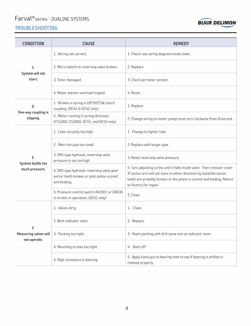
TROUBLESHOOTING
CONDITION CAUSE REMEDY
C.
System will not
start.
1. Wiring not correct. 1. Check–see wiring diagram inside timer.
2. Micro switch on reversing valve broken. 2. Replace.
3. Timer damaged. 3. Check per timer section.
4. Motor starter overload tripped. 4. Reset.
D.
One-way coupling is
slipping.
1. Broken a-spring in U9792CCW clutch
coupling. (DC41 & DC42 only).1. Replace
2. Motor running in wrong direction.
(CS1000, CS2000, DC41, and DC42 only).2. Change wiring to motor–pump must turn clockwise from drive end.
E.
System builds too
much pressure.
1. Lube viscosity too high. 1. Change to lighter lube.
2. Main line pipe too small. 2. Replace with larger pipe.
3. DR4 type hydraulic reversing valve
pressure is set too high3. Reset reversing valve pressure.
4. DR2 type hydraulic reversing valve gear
sector teeth broken or pilot piston scored
and binding.
4. Turn adjusting screw until it falls inside valve. Then remover cover.
If sector arm will not move in either direction by hand,the sector
teeth are probably broken or the piston is scored and binding. Return
to factory for repair.
5. Pressure control switch U620D1 or U6636
is erratic in operation. (DC41 only)5. Clean
F.
Measuring valves will
not operate.
1. Valves dirty. 1. Clean.
2. Bent indicator stem. 2. Replace
3. Packing too tight. 3. Ream packing with drill same size as indicator stem.
4. Mounting screws too tight. 4. Back off.
5. High resistance in bearing.5. Apply hand gun to bearing inlet to see if bearing is drilled or
reamed properly.

Farval®series - DUALINE SYSTEMS
9
NOTES

Farval®series - DUALINE SYSTEMS
10
NOTES

Farval®series - DUALINE SYSTEMS
11
NOTES

WWW.BIJURDELIMON.COM © 2016 BIJUR DELIMON INTERNATIONAL. ALL RIGHTS RESERVED. DL300• R3 (03/16)
UNITED KINGDOM
Denco Lubrication LimitedRamsden CourtRamsden Road Rotherwas Industrial EstateHereford, HR2 6LR
(+44) (0) 1432365000 TEL (+44) (0) 1432365001 FAX
CORPORATE HEADQUARTERS (USA)
Bijur Delimon International2100 Gateway Centre Blvd.Suite 109Morrisville, NC 27560
(919) 465 4448 TEL(800) 631 0168 TOLL-FREE (919) 465 0516 FAX
SPAIN
Lubricacion Centralizada de Limon S.A.Avenida Txori Erri 348150 Sondica Vicaya
(+34) 94-453-2000 TEL (+34) 94-453-2500 FAX
GERMANY
Bijur Delimon InternationalArminstrasse 1540227 Düsseldorf
(+49) 211 / 77 74-0 TEL (+49) 211 / 77 74-210 FAX
IRELAND
Bijur Lubricating Ireland LimitedGort RoadEnnis, County Clare
(+353) 6568-21543 TEL (+353) 6568-29667 FAX
CHINA
Nanjing Bijur Machinery Products, Ltd.#9 Hengtong RoadNanjing Xingang Economic & Technical Development ZoneNanjing 210038
(+86) 25-85801188 TEL (+86) 25-85802288 FAX
INDIA
Bijur Delimon India Private LimitedH-Block, A 56/1M.I.D.C., PimpriPune- 411018, Maharashtra
(+91) 2032319149 TEL (+91) 2027451725 FAX
FRANCE
Bijur Products, Inc.PB 50 - ZI de Courtabœuf9, Avenue de QuebecF-91942 Courtaboeuf Cedex
(+33) (0)169298585 TEL (+33) (0)169077627 FAX
Innovators of engineered lubrication technology since 1872
Bijur Delimon International has ISO 9001:2008 and ISO 14000 quality certifi ed manufacturing facilities around the world, so your centralized lubrication system meets the highest industry quality standards. It’s all part of our commitment to quality and customer service.