
D UTCH C OMMISSION ON B ONDS A Standing Committee of Dutch Society of Financial Analysts, VBA

Wide-CutTM
33"Combination Mower
Models 753BF753B
Operator’s Manual
Warning: This unit is equipped with an internal combustion engine and should not be used on or near any unimproved forest-covered, brush-cov-ered or grass-covered land unless the engine’s exhaust system is equipped with a spark arrester meeting applicable local or state laws (if any). If aspark arrester is used, it should be maintained in effective working order by the operator. In the State of California the above is required by law(Section 4442 of the California Public Resources Code). Other states may have similar laws. Federal laws apply on federal lands. A spark arresterfor the muffler is available by contacting the service department at Troy-Bilt LLC, P.O. Box 361131 Cleveland, Ohio 44136-0019.
IMPORTANT:READ SAFETY RULES AND INSTRUCTIONS CAREFULLY
TROY-BILT LLC, P.O. BOX 361131, CLEVELAND, OH 44136-0019
PRINTED IN USA FORM NO. 770-10602F(12/2003)
(fuel tank styles vary by engine model)

For more details about your unit, visit our website at www.troybilt.com
TABLE OF CONTENTSContent Page
Safety . . . . . . . . . . . . . . . . . . . . . . . . . . . . . . . . . . . . . . . . . . . . . . . . . . . . . . . . . . . . . . . . . . . 1
Assembly. . . . . . . . . . . . . . . . . . . . . . . . . . . . . . . . . . . . . . . . . . . . . . . . . . . . . . . . . . . . . . . . . 4
Features and Controls. . . . . . . . . . . . . . . . . . . . . . . . . . . . . . . . . . . . . . . . . . . . . . . . . . . . . . . 8
Operation . . . . . . . . . . . . . . . . . . . . . . . . . . . . . . . . . . . . . . . . . . . . . . . . . . . . . . . . . . . . . . . . 11
Maintenance . . . . . . . . . . . . . . . . . . . . . . . . . . . . . . . . . . . . . . . . . . . . . . . . . . . . . . . . . . . . . . 16
Off-Season Storage . . . . . . . . . . . . . . . . . . . . . . . . . . . . . . . . . . . . . . . . . . . . . . . . . . . . . . . . 24
Lubrications. . . . . . . . . . . . . . . . . . . . . . . . . . . . . . . . . . . . . . . . . . . . . . . . . . . . . . . . . . . . . . . 25
Troubleshooting . . . . . . . . . . . . . . . . . . . . . . . . . . . . . . . . . . . . . . . . . . . . . . . . . . . . . . . . . . . 27
Parts List . . . . . . . . . . . . . . . . . . . . . . . . . . . . . . . . . . . . . . . . . . . . . . . . . . . . . . . . . . . . . . . . . 28
Warrany Information . . . . . . . . . . . . . . . . . . . . . . . . . . . . . . . . . . . . . . . . . . . . . . . . . . . . . . . . Back Cover
FINDING MODEL NUMBERThis Operator’s Manual is an important part of your new Wide-Cut
TMmower. It will help you assemble, prepare and
maintain the unit for best performance. Please read and understand what it says.
Before you start assembling your new equipment, please locate the model plate on the equipment and copy the infor-mation from it in the space provided below. This information is very important if you need help from our CustomerSupport Department or an authorized dealer.
• You can locate the model number by looking at the rear surface of the mower frame. A sample model plate isexplained below. For future reference, please copy the model number and the serial number of the equipmentin the space below
ENGINE INFORMATIONThe engine manufacturer is responsible for all engine-related issues with regards to performance, power-rating,specifications, warranty and service. Please refer to the engine manufacturer’s Owner’s/Operator’s Manual packedseparately with your unit for more information.
CALLING CUSTOMER SUPPORTIf you have difficulty assembling this product or have any questions regarding the controls, operation or maintenanceof this unit, please call the Customer Support Department.
Call 1- (330) 558-7220 or 1- (800) 520-5520 to reach a Customer Support representative. Please haveyour unit’s model number and serial number ready when you call. See previous section to locate this in-formation. You will be asked to enter the serial number in order to process your call .
Copy Model Number Here
Copy Serial Number Here
www.troybilt.com
TROY-BILT LLCP. O. BOX 361131CLEVELAND, OH 44136
800-520-5520330-558-7220

Safety Alert Symbol
This is a safety alert symbol. It is used in thisOwner’s Manual to alert you to potential
hazards. Whenever you see this symbol, read and obey thesafety message that follows it. Failure to obey the safetymessage could result in personal injury or property damage.
The engine exhaust from this product containschemicals known to the State of California to cause cancer, birth defects, or other reproduc-tive harm.
WARNING:
1
IMPORTANT
Safe Operation Practices for Walk-Behind Mowers
This cutting machine is capable of amputating hands and feet and throwing objects. Failure to observe the following safety instructions could result in serious injury or death.
1. Read, understand, and follow all in-structions on the machine and in themanuals. Be thoroughly familiar withthe controls and the proper use ofthe mower before starting.
2. Do not put hands or feet near orunder rotating parts. Keep clear ofthe mower blade and dischargeopening at all times.
3. Only allow responsible individuals,who are familiar with the instruc-tions, to operate the mower.
4. Clear the area of objects such asrocks, toys, wire, bones, sticks, etc.,which could be picked up andthrown by the blade.
5. Be sure the area is clear of otherpeople before mowing. Stop mowerif anyone enters the area. Keep by-standers at least 25 feet away fromthe area of operation.
6. Do not operate the mower whenbarefoot or wearing open sandals.Always wear substantial foot wear.
7. Do not pull mower backwards unless absolutely necessary. Lookdown and behind before and whilemoving backwards.
8. Do not operate the mower withoutproper guards, plates, grass catcheror other safety protective devices inplace.
9. Refer to provided instructions forproper operation and installation ofaccessories. Only use accessoriesapproved by Garden WayIncorporated.
10. Stop the blade when crossing graveldrives, walks, or roads.
11. Stop the engine and disconnect thespark plug wire from the spark plug
whenever you leave the unit, beforecleaning the mower or uncloggingthe chute.
12. Shut the engine off, wait until theblade comes to a complete stop, anddisconnect the spark plug wire be-fore installing or removing themulcher cover or the optional grasscatcher. Make certain that the grasscatcher is securely attached beforeoperating the mower. Empty thegrass catcher after each use– decomposing debris could generateenough heat to catch fire.
13. Mow in daylight or good artificiallight.
14. Do not operate the mower whileunder the influence of alcohol ordrugs.
I. GENERAL OPERATION
Safety1Section

2
15. Never operate mower in wet grass.Always be sure of your footing; keepa firm hold on the handle and walk;never run.
16. Disengage the Wheel Drive Lever onself-propelled models before startingthe engine.
17. If the unit should start to vibrate ab-normally, stop the engine and dis-connect the spark plug wire. Thencheck immediately for the cause.Vibration is generally a warning oftrouble.
18. Always wear safety goggles or safetyglasses with side shields when oper-ating mower.
19. Watch for traffic when operatingnear, or when crossing roadways.
20. Never attempt to carry children orother passengers on the mower.They could fall off and be seriouslyinjured, or they could interfere withthe safe operation of the mower.
21. Check the operation of the OperatorPresence Control Bar before eachuse. See the Maintenance Section ofthis manual for instructions. If theengine runs longer than three sec-onds after the Operator PresenceControl Bar is released, the systemis not working properly. Immediatelycontact your local service dealer orthe factory Technical ServiceDepartment for instructions. Do notuse the mower until the mechanismis repaired.
22. The mower is equipped with a safetydischarge chute, comes with specialmulcher covers, and offers an op-tional grass catcher. The safety dis-charge chute must be working prop-erly at all times. Never attempt todisconnect or otherwise cause thisdischarge chute to cease working. Ifused, mulcher cover or grasscatcher attachment must be installedproperly and function correctly. Donot use your equipment otherwise.
23. Never run the engine in an enclosedarea. Engine exhaust contains carbonmonoxide, a deadly gas that is odor-less, colorless, and tasteless. Alwaysrun the engine outdoors and makesure there is adequate ventilation.
II. SLOPE OPERATIONSlopes are a major factor related toslip and fall accidents which can resultin severe injury. All slopes requireextra caution. If you feel uneasy on aslope, do not mow it.
DO:
Mow across the face of slopes; neverup and down. Exercise extreme cau-tion when changing direction onslopes. Avoid slopes greater than15o.
Remove objects such as rocks, treelimbs, etc.
Watch for holes, ruts, or bumps. Tallgrass can hide obstacles.
DO NOT:
Do not mow near drop-offs, ditches,or embankments. The operator couldloose footing or balance.
Do not mow excessively steep slopes.
Do not mow on wet grass. Reducedfooting could cause slipping.
III. CHILDRENTragic accidents can occur if the opera-tor is not alert to the presence of chil-dren. Children are often attracted to themower and to the mowing activity.Never assume that children will remainwhere you last saw them.
1. Keep children out of the mowingarea and under the watchful care ofa responsible adult.
2. Be alert and turn mower off if chil-dren enter the area.
3. Before and while moving backwards,look behind and down for small children.
4. Never allow children to operate themower.
5. Use extra care when approachingblind corners, shrubs, trees, or otherobjects that may obscure vision.
IV. SERVICE1. Use extra care in handling gasoline
and other fuels. They are flammableand their vapors are explosive.a) Use only an approved container.b) Never remove gas cap or add
fuel when the engine is running.Allow engine to cool before refu-eling. Do not smoke.
c) Never refuel the machine indoors.
d) Never store the machine or fuelcontainer inside where there isan open flame, such as a waterheater, etc.
e) Move mower away from anygasoline fumes before startingthe engine.
2. Never run an engine inside a closedarea.
3. Never make adjustments or repairswith the engine running. Disconnectthe spark plug wire and keep thewire away from the plug to preventaccidental starting.
4. Keep all nuts and bolts, especiallythe blade attachment bolts, tight andkeep equipment in good condition.
5. Never tamper with safety devices.Check their operation regularly.
6. Keep mower free of grass, leaves orother debris build-up. Clean up oil orfuel spillage. Allow mower to coolbefore storing.
7. After striking an object, stop the en-gine and disconnect the spark plugwire. Inspect the mower and repair,if necessary, before restarting.
8. Never attempt to make mower cut-ting height adjustments while theengine is running.
9. Grass catcher components are sub-ject to wear, damage and deteriora-tion, which could expose movingparts or allow objects to be thrown.Frequently check components andreplace with factory recommendedparts, when necessary.
Section 1: Safety

3
10. Mower blades are sharp and cancut. Wrap the blade or wear gloves,and use extra caution when servic-ing them.
11. Do not change the engine governorsetting or overspeed the engine.
12. Do not touch engine parts whichmay be hot from operation. Allowparts to cool completely before in-specting, cleaning or repairing themower.
13. To access the underside of themower, tip the mower rearward. Donot tip the mower forward or on ei-ther of its sides, unless specificallyadvised to do so in this manual.
14. Maintain or replace safety and in-structional decals. Refer to the sep-arate Parts Catalog for replacementdecal information.
15. For units equipped with electricstart:a) Batteries produce explosive
gases. Keep sparks, flame,cigarettes, etc., away. Ventilatethe area when charging the bat-tery. Do not charge the battery inan airtight space.
b) Do not use a battery chargerother than the one provided withthe mower.
c) The battery contains toxic mate-rials. Do not damage the batterycase. If the case is broken ordamaged, avoid contact with thebattery contents.
d) Properly dispose of a damagedor worn out battery. Check withlocal authorities for proper dis-posal methods.
e) Do not short circuit the battery.Severe burns and fire can result.
Section 1: Safety
SAFETY DECALSMake certain all safety decals on this equipment are kept clean and in good condition. The decals are shown (at reduced sizes)below. If you need a replacement decal, please refer to the Parts Catalog that accompanied this Manual.
WARNINGPINCH POINTS
Do not operate with-out all belt guards
in place.
Beneath belt/pulley cover
On Control Panel (for electric start model)
On Control Panel (for recoil start model)
On left side of mower deck
On discharge chute
4
INTRODUCTIONPlease carefully follow these assemblysteps to properly prepare your machinefor use. We recommend that you readthis Section in its entirety before begin-ning assembly.
NOTE: All references to left, right, frontand rear of the machine are determinedby standing behind the handlebars andfacing the direction of forward travel.
INSPECTION AFTER DELIVERYInspect the shipping crate and machineimmediately after delivery. Make sureneither the carton/crate nor the contentshave been damaged.
If you find or suspect any damage, con-tact the carrier (trucking company) immediately. Inform them of the specificdamage and that you wish to file a claim.To protect your rights, be sure to putthis in writing to the carrier within 15days. The carrier will let you know howto proceed with your claim. Please let usknow if you need any assistance.
TOOLS/MATERIALS NEEDED:• Wire Cutter• Two 7/16” Wrenches• 3/8” Wrench• 1/2” Wrench• Scissors or Pen Knife• Needle-nose Pliers• Tire Gauge
ASSEMBLY STEPS
STEP 1: Unpacking MowerNOTE: LEFT and RIGHT sides of the unitare as viewed from the operator’s posi-tion behind the handlebars.
1. Cut straps, if present, securing unitto pallet. Leave unit on pallet during as-sembly (to safely remove unit from pal-let, wait until you have completed as-sembly steps 1-4).
2. Remove any protective packagingfrom around the handlebars. Cut theplastic tie straps holding the control rodsand struts to the handlebars.
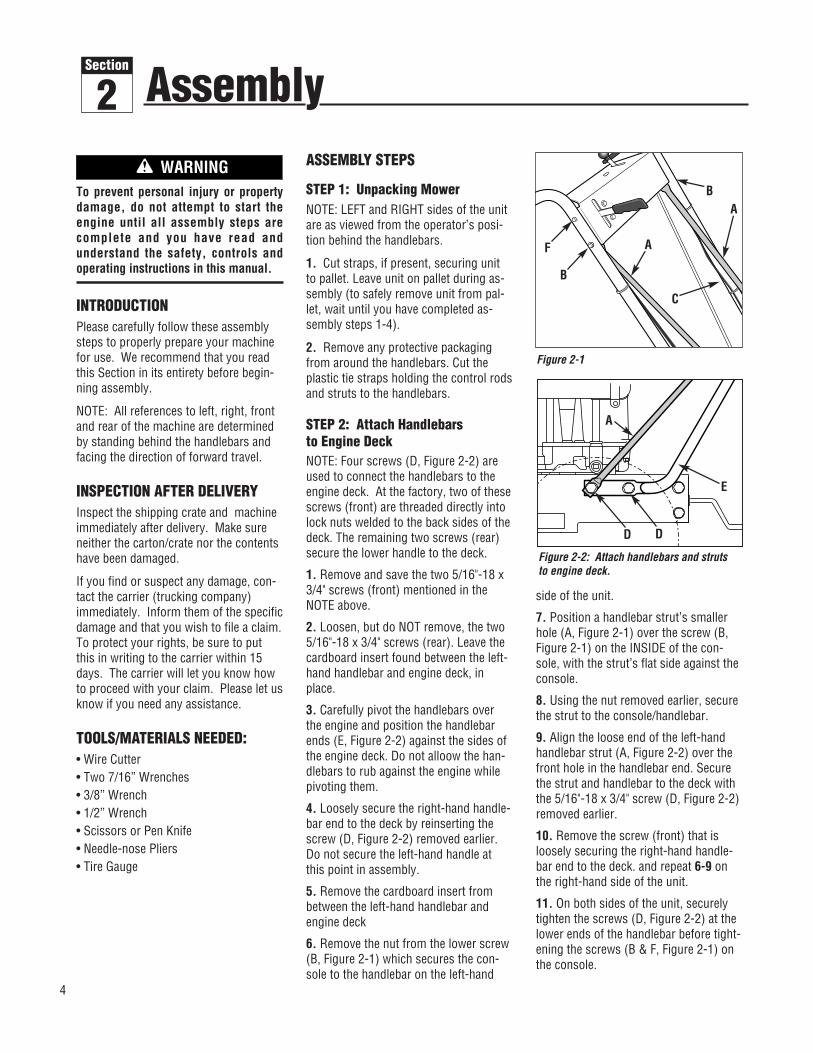
STEP 2: Attach Handlebars to Engine DeckNOTE: Four screws (D, Figure 2-2) areused to connect the handlebars to theengine deck. At the factory, two of thesescrews (front) are threaded directly intolock nuts welded to the back sides of thedeck. The remaining two screws (rear)secure the lower handle to the deck.
1. Remove and save the two 5/16"-18 x3/4" screws (front) mentioned in theNOTE above.
2. Loosen, but do NOT remove, the two5/16"-18 x 3/4" screws (rear). Leave thecardboard insert found between the left-hand handlebar and engine deck, inplace.
3. Carefully pivot the handlebars overthe engine and position the handlebarends (E, Figure 2-2) against the sides ofthe engine deck. Do not alloow the han-dlebars to rub against the engine whilepivoting them.
4. Loosely secure the right-hand handle-bar end to the deck by reinserting thescrew (D, Figure 2-2) removed earlier.Do not secure the left-hand handle atthis point in assembly.
5. Remove the cardboard insert frombetween the left-hand handlebar andengine deck
6. Remove the nut from the lower screw(B, Figure 2-1) which secures the con-sole to the handlebar on the left-hand
side of the unit.
7. Position a handlebar strut’s smallerhole (A, Figure 2-1) over the screw (B,Figure 2-1) on the INSIDE of the con-sole, with the strut’s flat side against theconsole.
8. Using the nut removed earlier, securethe strut to the console/handlebar.
9. Align the loose end of the left-handhandlebar strut (A, Figure 2-2) over thefront hole in the handlebar end. Securethe strut and handlebar to the deck withthe 5/16"-18 x 3/4" screw (D, Figure 2-2)removed earlier.
10. Remove the screw (front) that isloosely securing the right-hand handle-bar end to the deck. and repeat 6-9 onthe right-hand side of the unit.
11. On both sides of the unit, securelytighten the screws (D, Figure 2-2) at thelower ends of the handlebar before tight-ening the screws (B & F, Figure 2-1) onthe console.
To prevent personal injury or propertydamage, do not attempt to start the engine until all assembly steps arecomplete and you have read and understand the safety, controls and operating instructions in this manual.
WARNING
Figure 2-1
B
B
F
C
A
A
A
D
E
D
Figure 2-2: Attach handlebars and strutsto engine deck.
Assembly2Section

Section 2: Assembly
STEP 3 ATTACHING THE BATTERYCABLES (MODEL F753B)The positive battery terminal is markedPos. (+). The negative battery terminal ismarked Neg. (–).The mower is shipped with the positive(Red) cable secured to the positive ter-minal (+) on the battery. Attach theground (Black) cable to the negative ter-minal (–) on the battery, as follows:1. Remove the plastic battery cover (G,Figure. 2-3) by unthreading the two wingnuts (H, Figure. 2-3) which secure it tothe battery hold-down rods (I, Figure. 2-3)2. Remove the hex bolt and hex nutfrom the ground cable / heavy black wire(E, Figure. 2-3).3. Secure the ground cable to the nega-tive battery terminal (–) with the bolt andhex nut just removed.4. Resecure the battery cover.
IMPORTANT: • If the battery is put into service after
the date shown on top of battery,charge the battery as instructed in theMaintenence section of this manualprior to operating the tiller.
STEP 4: Attach Control Rods A. Attach Wheel Drive Control Rod1. Locate the wheel drive control rod (F,Figures 2-4A & 2-7) and remove the an-gled end from the left handlebar by re-moving the hairpin clip which secures itto the Wheel Drive Control lever (V,Figure 2-4A)
2. At left side of engine deck, insertswivel block (H, Figures 2-4 & 2-5) onwheel drive control rod into wheel drivecontrol arm (U, Figure 2-4).
3. Add a 5/16" washer (A, Figure 2-4)and secure with a hairpin clip (B).
4. At upper end of control rod, re-insert the angled end into the Wheel DriveControl lever (V, Figure 2-4A) and re-attach with hairpin clip (BB) removedearlier.
B. Attach Operator Presence ControlRod
1. Locate the Operator Presence Controlrod (E, Figures. 2-4 and 2-5). At bottomof control rod, insert swivel block (G,Figures 2-4 & 2-5) into control arm (T,Figure 2-4).
2. Add one 5/16" washer and securewith hairpin clip.
C. Attach Blade Drive Control Rod1. Locate the blade drive control rod (C,Figure 2-5). Insert one end of control rodinto blade drive bracket (D, Figure 2-5).Add one 5/16" washer and attach withhairpin clip (CC).
2. Insert the other end of rod into bot-tom end of Blade Drive Control lever (J,Figure 2-5). Add one 5/16" washer andattach with hairpin clip (AA).
D. Attach and Adjust Gear Select LeverNOTE: The retaining plate (N, Figure 2-5)mentioned in the following steps is se-cured to the rear of the mower with twoscrews (O, Figure 2-5) and 1/4”-20 lock-nuts. Remove the retaining plate andsave it, along with the two screws, be-fore proceeding with assembly.
Control rods are adjusted at the fac-tory and should not require additionaladjustment during assembly. After as-sembling unit, control rod adjustment should be checked (and re-adjusted, if necessary) according toinformation in Maintenance Section.
Failure to follow this instruction couldresult in severe personal injury or property damage.
WARNING
Figure 2-3: Connect wire terminals to battery terminals.
H
HG
I
Red(Positive Cable)
Black(Negative Cable)
Figure 2-4: Left-hand control rods detail.
F
H
E
W
G
U
A, B T
5

Section 2: Assembly
1. Remove the vinyl grip (B, Figure 2-6)from the gear select lever (I). Place thewood edge against the edge of the gripand slowly pull off the grip.
2. Insert nylon bushing (Z, Figure 2-6)up into console (L).
3. Slide spring and washers (J) downonto gear select lever.
4. Insert gear select lever (I) up throughnylon bushing (Z) in handlebar console(L). Guide pin (K) on gear select lever intogroove in shift quadrant (P).
5. Hold lower part of gear select lever (I,Figure 2-7) against bracket (M). Positionretaining plate (N), removed earlier, asshown in Figure 2-7 (plate belowbracket). Secure plate with two 1/4"-20 x1/2" screws (O) and 1/4”-20 locknuts re-moved earlier.
6. Slide grip (B, Figure 2-6) back ontogear select lever (I).
7. Rotate gear select lever (I, Figures 2-6 & 2-7) clockwise until spur (K - shortrod) on gear select rod stops in the neu-tral position detent on the shift patternquadrant (Figure 2-6).
8. Move shift arm (X, Figure 2-7) fromside to side as necessary into each trans-mission gear detent until transmission isin neutral.
NOTE: Moving shift arm (X) all the way tothe left, and then one notch back to theright, should put transmission into neu-tral. When transmission is in neutral, unitwill move freely when pushed while hold-ing the Operator Presence Control lever(W, Figure 2-5) down. If transmission isNOT in neutral, there will be a slight dragon the wheels when pushing unit.
Figure 2-4A: Attach wheel drive control rodto lever.
VF
BB
Figure 2-5: Rear view of control rods.
G N P O
H
F
E
I
C
J
AA
CC
D
L
M
V
W
Figure 2-6: Detail – Gear Select Lever in Neutral (N) position.
I
L
K
P
B
Z
Pin (K) must be in this detentwhen transmission neutral isadjusted.
J
6

7
Section 2: Assembly
9. When shift arm (X) is in neutral posi-tion, rotate shift link (P) toward end ofgear select lever rod (I). Adjust lengthof shift link (P) as necessary to fit intohole in bottom of gear select lever (I).
NOTE: Pin (K) on Gear Select Lever (I)must be held in the neutral position detent on the shift quadrant (see Figure2-6) while shift link (P, Figure 2-7) is adjusted.
10. Insert hooked end of shift link (P,Figure 2-7) into hole in bottom end ofgear select lever (I) and secure withhairpin clip (Q).
NOTE: It may be necessary to lift gearselect lever (I) to install shift link (P).
11. Remove unit from shipping crate.To remove, hold down OperatorPresence Control lever (W, Figure 2-5)which releases the wheel brake.
12. With unit on level ground, holddown Operator Presence Control lever(W, Figure 2-5) and push unit forwardand backward. The wheels should movefreely. If not, adjust length of shift link(P, Figure 2-7) as necessary.
13. Put the Gear Select Lever in neutral(N), release all of the control levers andtry to push the unit forward and back-ward. The wheels should not turn. Ifthey do turn, an adjustment is neces-sary. DO NOT OPERATE THE UNITUNTIL THE WHEEL BRAKE MECHANISMHAS BEEN ADJUSTED AND IS WORK-ING PROPERLY. See “Wheel BrakeAdjustment” in Section 5 “Maintenance.”
STEP 5: Secure Wire Harness
1. At the unattached end of the electricalwire harness, there are four wires at-tached to a large plastic connector andtwo wires attached to a small plasticconnector. . Plug the large connectorinto the bottom of the ignition keyswitchthat is located on the underside of thehandlebar console (not pictured).
3. Use two cable ties to secure the wireharness to the right handlebar and awayfrom any moving parts. Place the tiesan equal distance apart.
STEP 6: Check Motor Oil Level
1. Move mower to a level area. Pressand hold Operator Presence Controllever (W, Figure 2-5) to move mower.2. The mower is shipped with oil in theengine. However, you MUST check theoil level according to the instructions pro-vided in the separate Engine Owner’sManual included in the unit’s literaturepackage before starting the mower.
• Keep oil level at the FULL mark on thedipstick to avoid engine damage.
• Change oil according to schedule andinstructions in Section 5 “Maintenance.”
STEP 7: Check Tire Pressure1. Use a tire gauge to check the airpressure in the rear tires. The air pres-sure should be between 15-20 PSI (20PSI maximum).
2. Keep both tires equally inflated tohelp prevent machine from pulling toone side.
STEP 8: After Assembling andBefore Using Unit1. Read this entire Owner’s Manual forproper safety, operation and mainte-nance information.
2. Make sure spark plug wire is con-nected to spark plug before starting unit.
Figure 2-7: Detail – Transmission Neutral Adjustment.
P
I
X
YQ
MN
O
Do not use the mower if the wheelscontinue to turn after releasing theOperator Presence Control and theWheel Drive Control. Severe personal injury or propertydamage could result if this instructionis not followed.
WARNING
8
IMPORTANT: THE MOWER ISEQUIPPED WITH A BLADE-BRAKE-CLUTCH CONTROL SYSTEM WHICH ISDESIGNED TO STOP THE MOWERBLADES WITHIN THREE (3) SECONDSAFTER RELEASE OF THE OPERATORPRESENCE CONTROL. THIS SYSTEMWILL STOP THE BLADES BUT NOT THEENGINE. THEREFORE, YOU CAN DISEN-GAGE THE BLADE DRIVE AT ANYTIMEWITHOUT HAVING TO STOP ANDRESTART THE ENGINE. THIS FEATUREIS PARTICULARLY USEFUL WHEN YOUNEED TO CROSS GRAVEL DRIVES ORROUGH TERRAIN AND YOU DO NOTWANT THE SPINNING BLADES TO STRIKE STONES OR HIDDEN OBSTACLES.
MOWER FEATURES ANDCONTROLS
This section describes the variousfeatures and controls on the unit. Referto the next section “Operation” for detailed operating instructions. Also,read the separate Engine Owner’sManual for a detailed explanation of theproper use of the engine controls.
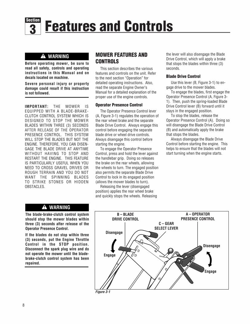
Operator Presence Control The Operator Presence Control lever
(A, Figure 3-1) regulates the operation ofthe rear wheel brake and the separateBlade Drive Control. Always engage thiscontrol before engaging the separateblade drive or wheel drive controls.Always disengage this control beforestarting the engine.
To engage the Operator PresenceControl, press and hold the lever againstthe handlebar grip. Doing so releasesthe brake on the rear wheels, allowingthe wheels to turn. The engaged positionalso permits the separate Blade DriveControl to lock in its engaged position(allows the mower blades to turn).
Releasing the lever (disengaged position) applies the rear wheel brakeand quickly stops the wheels. Releasing
the lever will also disengage the BladeDrive Control, which will apply a brakethat stops the blades within three (3)seconds.
Blade Drive ControlUse this lever (B, Figure 3-1) to en-
gage drive to the mower blades. To engage the blades, first engage the
Operator Presence Control (A, Figure 3-1). Then, push the spring-loaded BladeDrive Control lever (B) forward until itstays in the engaged position.
To stop the blades, release theOperator Presence Control (A). Doing sowill disengage the Blade Drive Control(B) and automatically apply the brakethat stops the blades.
Always disengage the Blade DriveControl before starting the engine. Thishelps to ensure that the blades will notstart turning when the engine starts.
Before operating mower, be sure toread all safety, controls and operatinginstructions in this Manual and on decals located on machine.
Severe personal injury or propertydamage could result if this instructionis not followed.
WARNING
The blade-brake-clutch control systemshould stop the mower blades withinthree (3) seconds after release of theOperator Presence Control.
If the blades do not stop within three(3) seconds, put the Engine ThrottleControl in the STOP position.Disconnect the spark plug wire and donot operate the mower until the blade-brake-clutch control system has beenrepaired.
WARNINGB – BLADE
DRIVE CONTROLA – OPERATOR
PRESENCE CONTROLC – GEAR
SELECT LEVER
Disengage
Engage
Engage
Figure 3-1
Features and Controls3Section
Disengage

9
Section 3: Features and Controls
Gear Select LeverUse this lever (C, Figure 3-1) to select
any of four forward ground speeds (1 -Slow, 2 and 3 - Medium, 4 - Fast), N(Neutral) and R (Reverse). The gear shiftpattern is shown in Figure 3-2.
To avoid damaging the transmis-sion, do not shift gears when themower is moving.
For forward travel, use one of the fournumbered settings. To select reverse,shift to neutral and then pull up on thelever. Turn the lever to the R (reverse)position and release the lever.
Put the lever in N (neutral) to manu-ally push the mower and when themower is not in use.
Wheel Drive ControlUse this lever (D, Figure 3-3) to en-
gage and disengage drive to the wheels.To engage the wheels, first select a
forward or reverse gear with the GearSelect Lever and squeeze the OperatorPresence Control (A, Figure 3-3). Then,squeeze the Wheel Drive Control lever(D) against the handlebar grip. Theground speed can be varied by increas-ing or decreasing pressure on the lever.To avoid sudden acceleration, slowlysqueeze the lever when first engagingthe wheels.
Release the Wheel Drive Control todisengage the wheels. The wheels willgradually slow to a stop. NOTE: To stopthe wheels quickly, release the Operator
Presence Control along with the WheelDrive Control.
When starting the engine, the WheelDrive Control should be disengaged (re-leased). This helps to ensure that thewheels will not start turning when theengine starts.
Cutting Height Control LeverUse this lever (E, Figure 3-4) to adjust
the cutting height from 1 to 4 inches.Note that actual cutting heights will varyaccording to soil conditions.
Turn the lever clockwise to raise theheight or counterclockwise to lower theheight. A decal and pointer (not illus-
trated) on the right side of the mowerdeck show the cutting height settingsranging from A (highest) to G (lowest).
Mulcher CoverThe mulcher cover (F, Figure 3-5) is
pre-installed at the factory. It must bekept in place when using the unit as amulching mower. The mulcher cover isdesigned to keep the discharge chuteraised up while you mow. When thecover is removed for side-dischargemowing, the discharge chute lowers.
Refer to “4. Select Mulching or Side-Discharge Mowing” in the OperationSection for mulcher cover installationinstructions.
Figure 3-2:Shift patternon console.
Operating Symbols Various symbols are used on the mower to indicate control settings (your model may not have all of thesymbols). These symbols are shown below with a description of their meaning.
FAST SLOW CHOKEENGINESTOP
ENGINESTART
ENGINERUNENGAGE DISENGAGE
Do not engage the Wheel Drive Controlwithout first engaging the OperatorPresence Control. Doing so could result in wear or damage to the wheelbrake mechanism.
CAUTION
A – OPERATOR PRESENCE CONTROL
D – WHEELDRIVE CONTROL
Disengage
Disengage
Engage
Engage
Figure 3-3
Figure 3-4
E – CUTTING HEIGHTCONTROL LEVER
F
Figure 3-5

10
Engine Throttle ControlThis lever (G, Figure 3-6) is used to
adjust engine speeds and, on non-Electric Start models, to stop the engine.Always run engine at fast speed settingfor best mower performance. The throt-tle settings are shown below.
Ignition/Starter Switch - (Electric Start Model)
This three-position switch (H, Figure3-6) is used to start and stop the engine on electric start models. The ig-nition key settings are shown below. Donot turn the key until you have read theOperation Section in this Manual.
Always remove ignition key whenleaving mower unattended or when in-specting, cleaning or servicing mower.
Engine Recoil StarterThe recoil starter (I, Figure 3-7) is
used to “pull-start” the engine. Detailedinstructions for using the recoil starterare found in the Operation Section of thisManual and in the Engine Owner'sManual. Do not pull the recoil starteruntil you have read the OperationSection.
Section 3: Features and Controls
STOP - Stops engine.
RUN - After starting, key returns to run position.
START - Starts engine.Release key when enginestarts.
Figure 3-6
G – THROTTLE CONTROL
H – IGNITION/STARTERSWITCH
CHOKE - Use when starting a cold engine.
FAST - Use during moweroperation.
SLOW - Use when idlingengine.
STOP - Stops engine(Non-electric Start ModelsOnly)
I – RECOILSTARTER
Figure 3-7

11
BEFORE OPERATING MOWER
1. Pre-Operation ChecklistWith the spark plug wire disconnectedfrom the spark plug, perform the follow-ing checks and services before each use:
1. Review Section 1: “Safety” and Section3, “Features and Controls” in this man-ual. Read the separate Engine Owner’sManual provided with the unit.
2. Check unit for loose or missing hard-ware. Tighten or replace as needed.
3. With the unit on level ground, checkthe engine oil level according to theinstructions in the Engine Owner’sManual. The oil level should be at theFULL mark on the dipstick or up to thetop of the oil fill hole on engines with-out a dipstick.
4. Check all levers for freedom of move-ment. Readjust or repair as neededbefore starting engine.
5. Check that all guards and shields arein place and properly secured.
6. Inspect the area to mowed and re-move any debris which could bepicked up and thrown by the mowerblades.
7. Check that the mulcher cover is prop-erly installed in the discharge opening(see instructions in this Section).Remove the mulcher cover to use theside-discharge mowing feature.
8. On electric start models, check thatall wiring connections are clean andtight.
9. Check the air pressure in the reartires (15-20 PSI). Keep tires inflatedequally.
10. Remove the fuel cap and check thelevel of gasoline according to the in-structions in the Engine Owner’sManual. Clean around fuel fill areabefore removing fuel cap. Do notcheck fuel level or add fuel while in-doors or if engine is running or hot.Allow engine to cool for three (3)minutes. Fill the tank with fresh,
clean unleaded gasoline with a mini-mum octane rating of 77. Leave 1/2"of space for fuel expansion. Do notmix oil with gasoline. Do not usegasoline which contains Methanol.See the Engine Owner’s Manual forinstructions and precautions regard-ing the use of gasolines that areblended with alcohols or ethers(called oxygenated or reformulatedgasolines). Securely replace caps onfuel tank and fuel container.
11. Attach spark plug wire to spark plugafter completing above checklist.
2. Set Mower Cutting Height
1. Release all controls before adjustingthe cutting height.
2. Adjust the cutting height from 1 to 4inches by rotating the Cutting HeightControl lever (Figure 3-4) either clock-wise to raise the height or counterclock-wise to lower the height. Note that ac-tual cutting heights will vary accordingto grass and soil conditions. A decal andpointer on the right side of the mowerdeck indicates the height setting.
3. In heavy or tall grass, it is usuallybetter to make the first cut at a highersetting and then make a second cut atthe desired height. In rough terrain, ahigher setting is recommended as it willminimize the chances of the blade strik-ing the ground or hidden obstructions.
Before operating mower, be sure toread all safety, controls and operatinginstructions in this Manual and on decals located on machine.
Severe personal injury or propertydamage could result if this instructionis not followed.
WARNING
GASOLINE IS HIGHLY FLAMMABLE ANDITS VAPORS ARE EXPLOSIVE. To helpprevent severe personal injury or prop-erty damage:• Follow gasoline safety rules inSection 1: “Safety” of this Manual andin the separate Engine Owner’sManual.• Never remove the gasoline fill cap oradd fuel when indoors or when engineis running or still hot. Allow engine tocool at least three (3) minutes beforerefueling.• Keep smoking materials, sparks orflames far away from fuel tank and fuelcontainer.• Store gasoline in an approved fuelcontainer and in a well-ventilated area.Store it safely out of the reach of chil-dren. Do not store gasoline where va-pors can reach an open spark or flameor where ignition sources are present(such as hot water or space heaters,furnaces, clothes dryers, stoves, elec-tric motors, etc.).• Fill tank to 1/2" below bottom of fillerneck to allow for fuel expansion. Wipeup spilled gasoline immediately andmove mower away from gasoline fumesbefore starting engine. Securely re-place caps on fuel tank and fuel container.
DANGER
To avoid personal injury, do not adjustcutting height while wheels or bladesare turning. Release all handlebarcontrols and wait for all motion to stopbefore adjusting cutting height.
CAUTION
Operation4Section
12
3. Test Blade-Brake-Clutch Control System
The mower is equipped with a blade-brake-clutch which is designed to stopthe mower blades within three (3) seconds after release of the OperatorPresence Control or the Blade DriveControl. Never tamper with, or attemptto defeat the purpose of this safety device.
The control system is a mechanicaldevice which is subject to wear.Therefore, test the operation of theblade-brake-clutch control system beforeeach use of the mower. Refer to "BladeBrake Control Test" at the end of thisSection.
4. Select Mulching or Side-Discharge Mowing
You can use the mower either as amulching mower or as a side-dischargemower. To use the mulching feature, in-sert the mulcher cover as describedbelow. Remove the mulcher cover toside-discharge grass clippings. Themulcher cover is designed to keep thedischarge chute raised up while mowing.When the cover is removed, the dis-charge chute will lower itself for side-discharge mowing.
To install or remove mulcher cover:
1. Stop the engine and wait for all partsto stop moving. Disconnect the sparkplug wire from the spark plug. Removethe ignition key on electric start models.
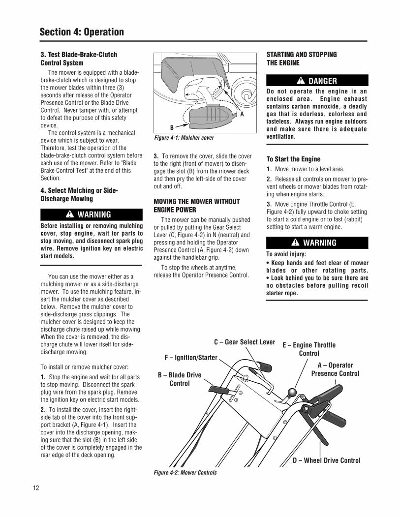
2. To install the cover, insert the right-side tab of the cover into the front sup-port bracket (A, Figure 4-1). Insert thecover into the discharge opening, mak-ing sure that the slot (B) in the left sideof the cover is completely engaged in therear edge of the deck opening.
3. To remove the cover, slide the coverto the right (front of mower) to disen-gage the slot (B) from the mower deckand then pry the left-side of the coverout and off.
MOVING THE MOWER WITHOUTENGINE POWER
The mower can be manually pushedor pulled by putting the Gear SelectLever (C, Figure 4-2) in N (neutral) andpressing and holding the OperatorPresence Control (A, Figure 4-2) downagainst the handlebar grip.
To stop the wheels at anytime, release the Operator Presence Control.
STARTING AND STOPPING THE ENGINE
To Start the Engine1. Move mower to a level area.
2. Release all controls on mower to pre-vent wheels or mower blades from rotat-ing when engine starts.
3. Move Engine Throttle Control (E,Figure 4-2) fully upward to choke settingto start a cold engine or to fast (rabbit)setting to start a warm engine.
Section 4: Operation
Before installing or removing mulchingcover, stop engine, wait for parts tostop moving, and disconnect spark plugwire. Remove ignition key on electricstart models.
WARNING
To avoid injury:• Keep hands and feet clear of mowerblades or other rotating parts.• Look behind you to be sure there areno obstacles before pulling recoilstarter rope.
WARNING
Figure 4-1: Mulcher cover
B
A
Figure 4-2: Mower Controls
A – OperatorPresence ControlB – Blade Drive
Control
C – Gear Select Lever
D – Wheel Drive Control
E – Engine ThrottleControlF – Ignition/Starter
Do not operate the engine in an enclosed area. Engine exhaust contains carbon monoxide, a deadlygas that is odorless, colorless andtasteless. Always run engine outdoorsand make sure there is adequate ventilation.
DANGER

Section 4: Operation
4. To start engine using recoil starter:
A. Stand on left side (as viewed frombehind handlebars) of machine. Besure your feet are safely away fromthe underside of the mower deck andall mower controls are released.Place one foot on top of tire.
B. Grasp starter rope handle (Figure 3-7) and pull slowly until rope pullsslightly harder. Let rope rewindslowly. Then pull rope with a rapid,full arm stroke. Let rope returnslowly. If engine fails to start afterthree pulls, repeat instructions start-ing with Step 2 (try setting throttle atfast setting).
C. When engine starts, operate in fastthrottle setting (move throttle fromchoke setting to fast setting).
5. To start engine using electric starter:
A. Stand behind the handlebars and re-lease all mower controls.
B. Turn ignition key (F, Figure 4-2) fullyclockwise to crank engine. To avoiddamage to starter motor, do notcrank engine for longer than five sec-onds at a time. Also, allow 15 sec-onds between each start attempt. Ifengine fails to start after three at-tempts, repeat instructions startingwith Step 2 (try setting throttle at fastsetting).
C. When engine starts, release key and itwill return to the run (middle) posi-tion.
D. Operate engine at fast throttle setting(move throttle from choke setting tofast setting).
NOTE: If the electric start system is notfunctioning, the engine can be startedwith the recoil starter. To do so, first putthe ignition key in the run (middle) posi-tion. Then follow Steps 1-4 above.Leave the key in the run position duringengine operation.
To Stop the Engine1. Release all mower controls to stopwheels or mower blade.
2. Move throttle control down to slow(turtle) position. (Whenever possible,gradually reduce engine speed beforestopping engine.)
3. Move Throttle Control all the waydown to stop position (Non-electric StartModels Only) or turn ignition key (elec-tric start models) fully counterclockwiseto stop position.
4. On electric start models, remove theignition key before leaving the mowerunattended.
ENGAGING THE BLADESTo Engage the Blades1. Start engine as described in “To Startthe Engine” instructions. Put enginethrottle in fast speed setting.
2. Press and hold Operator PresenceControl (A, Figure 4-2) against handle-bar grip.
3. Slowly push Blade Drive Control (B,Figure 4-2) fully forward until it stays inthe engaged position. The blades arenow rotating.
To Stop the BladesTo stop the blades, release the OperatorPresence Control.
TO ENGAGE THE WHEELS
1. Start engine as described in “ToStart the Engine” instructions.
2. FOR FORWARD TRAVEL:
A. Press and hold Operator PresenceControl (A, Figure 4-2) against han-dlebar grip.
B. Put the Gear Select Lever (C, Figure4-2) into one of the numbered set-tings (1 - Slow, 2 and 3 - Medium, 4- Fast). When first practicing with
the mower, put lever in No. 1 setting.Select forward speeds according tomowing conditions and terrain. Useslower speeds on rough terrain orwhen grass is heavy or thick. Theforward speed can be increased onsmooth terrain or if the grass coveris light. Allow the wheels to stopcompletely before shifting from oneforward speed into another.
C. To start the wheels, slowly squeeze
the Wheel Drive Control (D, Figure 4-2). The harder you squeeze, thefaster the wheels will turn. To avoidsudden acceleration, slowly squeezethe lever.
D. TO STOP THE WHEELS:• To stop drive power to the wheels,
release the Wheel Drive Control. Thewheels will gradually slow to a stop.
• To quickly stop the wheels, releaseboth the Wheel Drive Control andthe Operator Presence Control.
3. FOR REVERSE TRAVEL:
A. Stop the mower blades and wheels by
releasing the Operator PresenceControl (A, Figure 4-2).
B. Press and hold Operator PresenceControl against handlebar grip.
To avoid injury from rotating blades,keep face, hands and feet clear ofmower blades at all times.
DANGER
To avoid injury or property damage:• Look behind the mower before and during reverse operation.• Stop the mower blades before operat-ing in reverse.
WARNING
Before engaging the Wheel Drive Leverfor the very first time, check that theneutral (N) position on the Gear SelectLever is properly adjusted. See“Neutral Adjustment” in Section 5:Maintenance for the procedure to follow.
Failure to follow this instruction couldresult in personal injury or propertydamage.
WARNING
• To avoid damaging the transmission,do not shift gears while in motion.
• To avoid damaging the wheel brakemechanism, do not engage the WheelDrive Control without first engaging theOperator Presence Control.
CAUTION
13

Section 4: Operation
C. Put the Gear Select Lever (C, Figure4-2) in R (reverse) setting by firstmoving lever to N (neutral). Thenpull lever up, turn it to R position,and release lever.
D. To start the wheels, slowly squeezeWheel Drive Control (D, Figure 4-2).To avoid sudden acceleration, slowlysqueeze the lever.
E. TO STOP THE WHEELS:• To stop drive power to the wheels,
release the Wheel Drive Control. Thewheels will gradually slow to a stop.
• To quickly stop the wheels, releaseboth the Wheel Drive Control andthe Operator Presence Control.
• Return the Gear Select Lever to theN (neutral) position when you havecompleted reverse operation. Allowthe wheels to stop completely be-fore shifting from R (reverse) into aforward speed.
The mower turns easily by pushingthe handlebars in the opposite directionthat you want to turn. The differentialmechanism inside the transaxle willallow the inside turning wheel to stop orslow down while the outside turningwheel is powered by the drive system.
Reduce the wheel speed before turn-ing the mower. For tight turns, disen-gage the Wheel Drive Control and manu-ally push the mower through the turn (ifneeded, put the Gear Select Lever inneutral so the wheels turn freely).
MOWING TIPS AND HINTS
Mow When Lawn Is Dry
For best results, avoid cutting grasswhen it is wet. Wet grass tends to formclumps which interfere with the cuttingaction. The best time to mow is in thelate afternoon or early evening when thegrass is usually dry.
Cut Top 1/3 of Grass Blades
Cutting more than 1/3 of grass lengthmay cause the grass to become exces-sively dry. In tall grass, it may be neces-sary to mow at a higher setting and thenmow again at the desired height. NOTE:The cutting height is critical to achievinga well-groomed lawn. You should exper-iment with various settings to find that“just right” cutting height.
Vary Cutting Pattern
Vary the cutting pattern from week toweek to help prevent matting of thegrass. One week, mow from north tosouth, the next week mow from east towest. Overlap several inches whenmowing to obtain an even appearance.
Mowing on Slopes
Do not mow excessively steep slopes(see WARNING statement that follows).Slow down and exercise extreme cautionwhen changing direction on slopes.Before mowing on slopes, check the en-gine oil level and make sure that the levelis at the FULL mark. Maintaining a FULLoil level is particularly important whenoperating on slopes as oil can be drainedaway from vital engine parts.
Mulching Leaves
• The mower can be used to mow fallenleaves. The leaf particles filter down intothe lawn and provide added fertilizer.
• The leaves must be dry in order to bemulched.
• Use a slower ground speed if theleaves are not mulched into fine parti-cles.
• If you mulch oak leaves (which add acidto the soil), add lime to the lawn in thespring to reduce the acidity of the soil.
Keep Mower Blades SharpFor best mower performance, keep the
blades sharp. Dull blades will tear,bruise and split the ends of grass. Seeblade sharpening instructions in Section5: Maintenance.
Clean Mower FrequentlyClean the underside of the mower deck
frequently to remove grass build-up.See mower cleaning instructions inSection 5: Maintenance.
Precision TrimmingFor precision trimming, use the slow-
est gear and inch the mower along by“feathering” the Wheel Drive Controllever. Or, disengage the wheel drive byreleasing the Wheel Drive Control so thatyou can manually maneuver the mower(if needed, put the Gear Select Lever inneutral so that the wheels turn freely).
MAKING TURNS
13
To avoid injury or property damage:• Before mowing, thoroughly inspectarea where mower is to be used and remove all stones, sticks, wires,bones, nails and other foreign objects.• Disengage mower blades beforecrossing gravel drives, roads, or side-walks to prevent blades from throwingstones or other hazardous objects.
WARNING
To avoid injury or property damage:• Maximum safe operating angle is 15o.• Exceeding maximum safe operatingangle may cause tipping or loss of footing.• Do not mow wet slopes.• Mow across slopes, not up and down.• Exercise extreme caution whenchanging direction on slopes.
WARNING
14

15
Section 4: Operation
BLADE BRAKE CONTROL TESTWhen the Operator Presence Control
is released during operation of themower, the engine does not stop, butthe blades should stop within three (3)seconds. The following test provides avisual test of whether the Blade BrakeControl System is functioning. Performthis test before each use of the mower.
1. Park mower on a portion of lawnwhich has not been recently mowed.
2. Set the cutting height so the mowercuts 1/3 of the grass height.
3. Start the engine.
4. Press the Operator Presence Controldown against the handlebar grip andpush the Blade Drive Control fully for-ward until it stays in the engaged posi-tion.
5. Put the Gear Select Lever in the No. 1setting.
6. Engage the wheels with the WheelDrive Control and drive the mower forseveral feet. Then release the OperatorPresence Control.
A. Look at the lawn just mowed. Thelawn should be cut up to the pointwhere the Operator Presence Controlwas released.
B. Press the Operator Presence Controlagainst the handlebar grip but DONOT re-engage the Blade DriveControl. Drive the mower forwardfor several more feet. Release theOperator Presence Control and lookat the lawn. The grass should NOThave been cut. This indicates thatthe Operator Presence Control hasdisengaged the blade drive andstopped the blades.
7. If the mower cuts the grass in Step6-B, the Operator Presence Control isNOT disengaging the blade drive.Immediately stop the engine, discon-nect the spark plug wire, and move thewire away from the spark plug.
8. Do not use the mower until the BladeBrake Control System has been in-spected, adjusted or repaired by an au-thorized dealer.
To avoid personal injury or propertydamage, make sure that the mower ison grass, and that the test area is clearof foreign objects and bystanders be-fore you begin the Blade Brake ControlTest.
If the Operator Presence Control or theBlade Drive Control are not adjustedcorrectly, the blades may continue torotate after release of the OperatorPresence Control. If the blades do notstop within three (3) seconds of releaseof the Operator Presence Control, movethe Engine Throttle Control to the STOPposition, disconnect the spark plugwire, and move the wire away from thespark plug. Do not operate the moweruntil the Blade Brake Control Systemhas been repaired.
Failure to do this could result in per-sonal injury or property damage.
WARNING

Carefully read this Section on mowerand engine maintenance and service.Performing the required maintenanceaccording to schedule will ensure theproper performance and long life of yourmachine.
NOTE: All references to left, right, frontand rear of the machine are determined bystanding behind the handlebars and facingthe direction of forward travel.
IMPORTANT: REFER TOMAINTENANCE CHART IN THISSECTION FOR A LISTING OF REGU-LARLY SCHEDULED MAINTENANCEPROCEDURES.
ENGINE SERVICERoutine engine service is describedbelow. For more complete engine ser-vice information, refer to the enginemanual provided with your machine.For complete engine service, contact anauthorized engine dealer.
ENGINE OILOIL LEVEL: With mower on levelground, the engine oil level must be be-tween the "ADD" and "FULL" marks onthe dipstick at all times. Check beforeeach use and every 5 operating hours.
OIL CHANGE: On a new engine, changeoil after first 2 hours of use, then changeoil regularly as specified on the
Maintenance Chart. Refer to EngineOwner's Manual for oil capacity.
OIL TYPE: Use clean, high quality deter-gent oil having an A.P.I. service classifi-cation of SE, SF or SG. Use no specialadditives with oil. Refer to the EngineOwner’s Manual for recommended SAEviscosity grades that match the startingtemperature anticipated before the nextoil change.
Checking Oil Level:1. Park machine on level ground.
2. Stop engine, wait for parts to stopmoving, and disconnect spark plugwire.
3. Clean area around dipstick (Z, Figure5-1) to prevent dirt from entering oil fillhole.
4. Remove dipstick. Oil level must bebetween “ADD” and “FULL” marks. Donot exceed “FULL” mark on dipstick.
5. To add oil, pour slowly into dipstickopening. While adding, check oil levelfrequently by securely replacing dipstickand removing to read oil level. Wipe dip-stick clean each time oil level ischecked.
6. After filling to “FULL” mark, securelyreplace dipstick.
Changing Oil:Change oil while engine is still warmfrom recent operation. Warm oil flowsmore freely and carries away more im-purities.
1. Stop engine, wait for parts to stopmoving, and disconnect spark plugwire.
2. Remove dipstick (Z, Figure 5-1).
3. Remove protective cap (A, Figure 5-2) to expose oil drain port (B).
4. Push oil drain hose (D) (included inhardware bag with unit) onto oil drainport. Route other end of hose to an ap-propriate oil collection receptacle.
5. Twist oil drain fixture (C) to the openposition. Pull out. Drain oil completely.
6. Push in and twist oil drain fixture tothe closed position. Remove drainhose. Replace protective cap (A).
7. Refill engine with fresh oil and se-curely replace dipstick.
NOTE: Please dispose of all waste mate-rials in an ecologically responsible man-ner. Use proper waste material storagecontainers.
Before inspecting, cleaning or servicingthe machine, shut off engine, makesure that all moving parts have come toa complete stop, disconnect spark plugwire and move wire away from sparkplug. Remove ignition key on electricstart models.
Failure to follow these instructions canresult in personal injury or propertydamage.
WARNING
Figure 5-1: Briggs and Stratton engine oilfill.
Z
Figure 5-2: Oil drain.
CA
BD
Maintenance5Section
Before inspecting, cleaning or servicing the machine, shut off engine, wait for moving parts to stop, disconnect sparkplug wire and move wire away from spark plug. Remove ignition key (electric start models).Failure to follow these instructions can result in serious personal injury or property damage.
WARNING
16

17
Section 5: Maintenance
ENGINE CLEANING• Stop engine, wait for parts to stopmoving, disconnect spark plug wire,and allow engine to cool before in-specting or cleaning engine.
• Daily or more often, before running en-gine, remove grass and chaff from recoilfinger guard or rotating screen to preventengine damage caused by overheating.Also keep cooling vanes, governor link-age, springs and controls free of debris.
• Daily or more often, before running en-gine, clean muffler area (be sure muffleris cool) to remove all grass and com-bustible debris. If engine is equippedwith a spark arrestor screen, remove as-sembly every 50 hours for cleaning andinspection. Replace if damaged.
• Grass or chaff may clog engine's aircooling system, especially after pro-longed operation cutting tall, dry grass.See Engine Owner's Manual for instruc-tions on cleaning underneath the engineblower housing.
AIR CLEANER SERVICEImproper air cleaner maintenance cancause engine damage. Refer to theEngine Owner's Manual for more com-plete air cleaner service information.
SERVICE SCHEDULE:Outer foam pre-cleaner - wash and re-oilevery 25 operating hours or every sea-son, whichever occurs first.
Inner paper cartridge - clean or replaceevery 100 operating hours or every sea-son, whichever occurs first.
To Service Air Cleaner (Figure 5-3):
1. Stop engine, wait for parts to stopmoving, and disconnect spark plugwire.
2. Unscrew mounting screws and/or re-move knobs (D). Remove covers (E).Remove paper cartridge (B) and foampre-cleaner (A). Separate foam pre-cleaner from paper cartridge.
3. Wash foam pre-cleaner (A) in liquid
detergent and warm water. Squeeze dryin a clean cloth.
4. Saturate foam pre-cleaner in cleanengine oil. Wrap in clean, absorbentcloth and squeeze to remove all excessoil.
5. Replace paper cartridge (B), if necessary.
6. Reassemble air cleaner components.Tighten knobs/screws (D) securely.Secure cover assembly (E) on aircleaner body.
SPARK PLUGInspect the spark plug (Figure 5-4) afterevery 100 hours of operation. Be surethe gap is set at .030". Do not reuse plugif it is severely worn or damaged.
Best results are obtained with a newplug. See Engine Owner's Manual to de-termine proper replacement plug. Useof incorrect plug can cause engine dam-age.
NOTE: Do not clean spark plug in ma-chines which use abrasive grit. Cleanspark plug by scraping or wire brushing,or washing with a commercial solvent.
BATTERY (if applicable)Charge battery if unit is to be stored forlonger than three weeks. During themowing season, the battery is keptcharged by the charging system on theengine.
To Charge Battery:
1. Plug charger connector into wire har-ness connector located below ignitionswitch in handlebar console.
2. Plug charger into 120V wall outlet.(Note that battery charger is designed foruse indoors and should not be exposed torain or snow.)
3. Charge battery for 24-48 hours if unitis to be stored for longer than threeweeks.
4. After charging, unplug charger fromoutlet, then unplug charger from con-nector on wire harness located belowhandlebar console.
CARBURETORThe carburetor is adjusted at the factory.It should not need to be reset. If blackexhaust is noted, check the air cleanerfirst. An over-rich mixture is usuallycaused by a poorly serviced or cloggedair cleaner element, not an improperlyadjusted carburetor. If readjustment isnecessary, refer to Engine Owner'sManual or contact your engine dealer.
Figure 5-3: Briggs and Stratton air cleanerassembly.
ED
BA
Figure 5-4: Spark plug.
.030" Feeler Gauge
Charge battery only with charger sup-plied with machine. Do not short circuitbattery wires. Remove any jewelry be-fore working on or near the battery orelectric start system. Failure to followthese instructions could result in per-sonal injury or property damage.
WARNING
Before inspecting, cleaning or servicing the machine, shut off engine, wait for moving parts to stop, disconnect sparkplug wire and move wire away from spark plug. Remove ignition key (electric start models).Failure to follow these instructions can result in serious personal injury or property damage.
WARNING

18
ENGINE STORAGEIf engine will be unused for 30 days ormore, prepare it for storage by followingthe recommended procedures found inthe Engine Owner’s Manual.
MOWER SERVICEThe following maintenance/repair proce-dures can be performed by either theowner or an authorized service dealer.See an authorized service dealer forcomplete mower service.
TIPPING MOWER FOR SERVICE
When servicing the underside of themower for any reason, the mowershould only be tipped backward on itsrear wheels (and securely propped up toprevent it from falling). Tipping themower forward or to either side couldresult in damage to engine.
TIP: Before tipping mower, install asmall plastic sandwich style bag underthe gas cap and tighten securely. Thiswill virtually eliminate any fuel seepagefrom the cap. Be sure to remove theplastic bag before re-using mower.
BELT COVER REMOVAL
The belt cover must be removed to per-form several maintenance procedures.
To Remove Belt Cover:
1. Stop engine, wait for all parts tostop moving, and disconnect sparkplug wire.
2. Remove four screws (R, Figure 5-5)and remove cover.
To Reinstall Belt Cover:
1. Position belt cover in place.
2. Secure with the four screws removedearlier.
BLADE SPINDLE BELT REPLACEMENTFollow this procedure to remove and re-place the blade spindle drive belt (re-move blade drive belt first; see “BladeDrive Belt Replacement” in this Section).
1. Stop engine, wait for all parts tostop moving and disconnect spark plugwire.
2. Remove belt cover (see “Belt CoverRemoval”).
3. Align sight holes (O, Figure 5-6) inpulley with spindle housing-to-mowerdeck mounting bolts (L).
4. Loosen screw (J) and rotate arm (K)to the rear.
5. Loosen four mounting bolts (L) se-curing spindle housing (beneath mowerdeck) to mower deck.
6. Slide spindle housing (with pulley at-tached) toward center.
7. Replace belt (N) with new belt. IMPORTANT: SET BLADES PERPEN-DICULAR (90°) TO EACH OTHER.
8. Rotate arm (K) to move spindlehousing and apply tension to belt. Beltcogs and pulley grooves must mesh to-gether. When applying moderate fingertension (8-12 lbs.), belt should deflectapproximately 1/2” (12.7 mm) at (P),midpoint of deck.
9. Tighten bolts (L) to 15 ft.-lbs. (20.3Nm). Tighten screw (J).
10. Blades must not contact deck.Check and readjust as needed.
11. Reinstall blade drive belt and beltcover (removed earlier).
Section 5: Maintenance
Before servicing underside of mower,stop engine, wait for all parts to stopmoving, and disconnect spark plugwire. Remove ignition key fromkeyswitch on electric start models.Failure to follow this instruction couldresult in personal injury or propertydamage.
WARNING
Do not operate unit without belt coverinstalled. Failure to follow this instruc-tion could result in personal injury orproperty damage.
WARNING
Figure 5-5: Belt cover removal.
R
BLADESMUST BE PERPENDICULAR
TO EACH OTHER
FRONT
Figure 5-6: Blade Spindle Belt.
N PJ O
M
LK
Before inspecting, cleaning or servicing the machine, shut off engine, wait for moving parts to stop, disconnect sparkplug wire and move wire away from spark plug. Remove ignition key (electric start models).Failure to follow these instructions can result in serious personal injury or property damage.
WARNING
19
Section 5: Maintenance
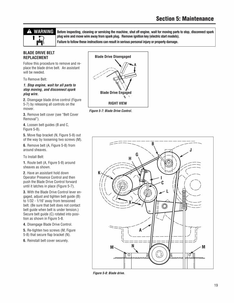
BLADE DRIVE BELT REPLACEMENTFollow this procedure to remove and re-place the blade drive belt. An assistantwill be needed.
To Remove Belt:
1. Stop engine, wait for all parts tostop moving, and disconnect sparkplug wire.
2. Disengage blade drive control (Figure5-7) by releasing all controls on themower.
3. Remove belt cover (see “Belt CoverRemoval”).
4. Loosen belt guides (B and C, Figure 5-8).
5. Move flap bracket (N, Figure 5-8) outof the way by loosening two screws (M).
6. Remove belt (A, Figure 5-8) fromaround sheaves.
To Install Belt:
1. Route belt (A, Figure 5-8) aroundsheaves as shown.
2. Have an assistant hold downOperator Presence Control and thenpush the Blade Drive Control forwarduntil it latches in place (Figure 5-7).
3. With the Blade Drive Control lever en-gaged, adjust and tighten belt guide (B)to 1/32 - 1/16" away from tensionedbelt. (Be sure that belt does not contactbelt guide when belt is under tension.)Secure belt guide (C) rotated into posi-tion as shown in Figure 5-8.
4. Disengage Blade Drive Control.
5. Re-tighten two screws (M, Figure 5-8) that secure flap bracket (N).
6. Reinstall belt cover securely.
Figure 5-7: Blade Drive Control.
RIGHT VIEW
Blade Drive Disengaged
Blade Drive Engaged
A
Figure 5-8: Blade drive.
BJ
CI
HG
K
L
A
X
M MN
Before inspecting, cleaning or servicing the machine, shut off engine, wait for moving parts to stop, disconnect sparkplug wire and move wire away from spark plug. Remove ignition key (electric start models).Failure to follow these instructions can result in serious personal injury or property damage.
WARNING
20
Section 5: Maintenance
BLADE BRAKE REPLACEMENTFollow this procedure to install a newblade brake.
To Remove Blade Brake:
1. Stop engine, wait for all parts tostop moving, and disconnect sparkplug wire.
2. Remove belt cover as described in“Belt Cover Removal” instructions.
3. Remove hardware (G, Figure 5-8) securing blade brake (H).
4. Remove old brake (H) from idler arm (I).
To Install Brake:
1. Position new brake (H) in place onidler arm (I).
2. Center brake in sheave groove andsecure brake (H) with hardware (G) re-moved earlier.
3. Reinstall belt cover securely.
4. Test operation of blade brake (see“Blade Brake Control Test” in Operationsection).
BLADE DRIVE BELT ADJUSTMENTIf the blade drive belt is slipping due tolack of belt tension, follow the stepsbelow.
1. Stop engine, wait for all parts tostop moving, and disconnect sparkplug wire.
2. Remove belt cover as described in“Belt Cover Removal” instructions.
3. With mower on level ground, adjustblade cutting height at about 3" (mea-sure from ground to flat portion ofblade).
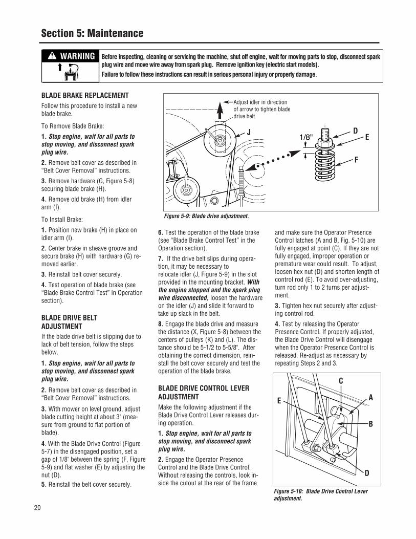
4. With the Blade Drive Control (Figure5-7) in the disengaged position, set agap of 1/8" between the spring (F, Figure5-9) and flat washer (E) by adjusting thenut (D).5. Reinstall the belt cover securely.
6. Test the operation of the blade brake(see “Blade Brake Control Test” in theOperation section).
7. If the drive belt slips during opera-tion, it may be necessary torelocate idler (J, Figure 5-9) in the slotprovided in the mounting bracket. Withthe engine stopped and the spark plugwire disconnected, loosen the hardwareon the idler (J) and slide it forward totake up slack in the belt.
8. Engage the blade drive and measurethe distance (X, Figure 5-8) between thecenters of pulleys (K) and (L). The dis-tance should be 5-1/2 to 5-5/8". Afterobtaining the correct dimension, rein-stall the belt cover securely and test theoperation of the blade brake.
BLADE DRIVE CONTROL LEVER ADJUSTMENTMake the following adjustment if theBlade Drive Control Lever releases dur-ing operation.
1. Stop engine, wait for all parts tostop moving, and disconnect sparkplug wire.
2. Engage the Operator PresenceControl and the Blade Drive Control.Without releasing the controls, look in-side the cutout at the rear of the frame
and make sure the Operator PresenceControl latches (A and B, Fig. 5-10) arefully engaged at point (C). If they are notfully engaged, improper operation orpremature wear could result. To adjust,loosen hex nut (D) and shorten length ofcontrol rod (E). To avoid over-adjusting,turn rod only 1 to 2 turns per adjust-ment.
3. Tighten hex nut securely after adjust-ing control rod.
4. Test by releasing the OperatorPresence Control. If properly adjusted,the Blade Drive Control will disengagewhen the Operator Presence Control isreleased. Re-adjust as necessary by repeating Steps 2 and 3.
Figure 5-9: Blade drive adjustment.
1/8"J D
E
F
Adjust idler in directionof arrow to tighten bladedrive belt
Figure 5-10: Blade Drive Control Leveradjustment.
B
E
D
A
C
Before inspecting, cleaning or servicing the machine, shut off engine, wait for moving parts to stop, disconnect sparkplug wire and move wire away from spark plug. Remove ignition key (electric start models).Failure to follow these instructions can result in serious personal injury or property damage.
WARNING

21
Section 5: Maintenance
WHEEL DRIVE BELT REPLACEMENTFollow this procedure to replace thewheel drive belt. 1. Stop engine, wait for all parts tostop moving, and disconnect sparkplug wire.2. Release all mower controls.3. Remove belt cover as described in“Belt Cover Removal” instructions.4. Locate wheel drive belt (O, Figure 5-11) and remove it from top sheave ofengine sheave, backsided idlers (P andQ) and transmission sheave (R).5. Install new belt as shown in Figure 5-11. Belt must be installed “inside out ”–“V” side of belt lies against engine sheave only. Flat side of belt liesagainst transmission sheave (R) andback-sided idlers (P and Q).6. Make sure belt is inside belt guide (S,Figure 5-11).7. Reinstall belt cover securely.8. An adjustment to the drive belt maybe necessary. See “Wheel Drive BeltAdjustment” in this Section.
WHEEL DRIVE BELT ADJUSTMENTThe wheel drive belt requires an adjust-ment if loss of drive belt tension (slip-page) occurs. This is most noticeablewhen more traction is required (such asgoing up slopes).
To Test Wheel Traction:1. Park machine on a paved (concrete,etc.) surface with front edge up againsta sturdy wall, fence, etc.2. Put Gear Select Lever in No. 1 setting.IMPORTANT: DO NOT PARK AGAINST APAINTED OR SIDED WALL. TESTINGTHE WHEEL DRIVE SYSTEM REQUIRESMACHINE TO BE FORCIBLY PUSHEDAGAINST WALL. DAMAGE TO PAINT ORSIDING COULD RESULT.3. With engine running, and machineplaced firmly up against wall, hold downOperator Presence Control and fully en-
gage wheel drive by squeezing WheelDrive Control until it contacts handlebar.4. Wheels should slip on paved surface.If they do not, an adjustment is required.
To Adjust Wheel Drive Belt:1. Stop engine, wait for all parts tostop moving, and disconnect sparkplug wire.2. Remove cotter pin (A, Figure 5-12A)from upper end of Wheel Drive Controlrod. Slide rod out of lever assembly.3. Loosen jam nut (D, Figure 5-12).4. Thread rod (E, Figure 5-12) one ortwo turns clockwise for more tension orcounterclockwise for less tension.5. Insert rod back into hole in WheelDrive Control lever and install cotter pin.Bend ends of cotter pin to secure.6. Retest wheel traction. Repeat adjust-ment procedure, if necessary. Mostcomfortable operation will be obtainedwhen the adjustment allows the lever tojust make contact with the handgrip assufficient wheel traction is achieved.When adjustment is complete, tightenjam nut (D) firmly against block (B).
WHEEL BRAKE ADJUSTMENTThis adjustment may be required if themachine does not hold on a hill with theOperator Presence Control disengaged,or if the brake drags with the OperatorPresence Control engaged and the trans-mission in neutral.
1. Stop engine, wait for all parts tostop moving, and disconnect sparkplug wire.
2. Disengage (release) the OperatorPresence Control (M, Figure 5-13).
Figure 5-11: Wheel drive belt replacement.
S
OQ
P
R
Figure 5-12A
A
Before inspecting, cleaning or servicing the machine, shut off engine, wait for moving parts to stop, disconnect sparkplug wire and move wire away from spark plug. Remove ignition key (electric start models).Failure to follow these instructions can result in serious personal injury or property damage.
WARNING

Section 5: Maintenance
3. Slowly adjust at nut (O), if necessary,until the distance between the back ofbrake arm (N) and bracket (P) is 3/8”-5/16". Use small adjustments (1/4 turnmaximum). NOTE: It may be necessaryto relieve spring tension when decreas-ing distance. To do so, have an assis-tant engage the Operator PresenceControl while you adjust the nut.
TRANSMISSION NEUTRAL ADJUSTMENTFollow this procedure to adjust neutralon the transmission. 1. Stop engine, wait for all parts tostop moving, and disconnect sparkplug wire.
2. Rotate shift rod (I, Figures 5-14 and5-15) clockwise until it stops in the neu-tral (N) position (from forward gear positions).3. Hold down Operator Presence Control(M, Figure 5-13) and push unit forwardand backward. Unit should move freely.If not, continue with Step 4.4. Remove cotter pin securing shift link(P, Figure 5-15) to shift rod (I).5. Move shift arm (X) back and forth asnecessary into each detent until trans-mission is in neutral. NOTE: Movingshift arm (X) clockwise all the way to theleft, and then one notch back counter-clockwise, should put transmission intoneutral. When transmission is in neutral,unit will move freely when pushed whileholding the Operator Presence Controllever down. If transmission is NOT inneutral, there will be a slight drag on thewheels when pushing unit.6. When shift arm (X) is in neutral posi-tion, rotate shift link (P) until hookedend fits back into hole in bottom end ofshift rod (I). NOTE: Shift rod (I) must beheld in the neutral position (see Figure5-14) while shift link (P) is adjusted.7. Secure shift link (P) into shift rod (I)with cotter pin removed earlier.8. Re-check neutral by pushing unitback and forth and shifting lever (I) fromreverse to neutral. A small fine-tune adjustment may be required.
Figure 5-12: Wheel drive belt adjustment.
E
D
B
Figure 5-13: Wheel brake adjustment.
Figure 5-14: Lever in neutral (N) position.
M
N
O
N
O
P
I
Detent forNeutral Position
3/8"-5/16"
Before inspecting, cleaning or servicing the machine, shut off engine, wait for moving parts to stop, disconnect sparkplug wire and move wire away from spark plug. Remove ignition key (electric start models).Failure to follow these instructions can result in serious personal injury or property damage.
WARNING
22
Section 5: Maintenance
MOWER BLADES
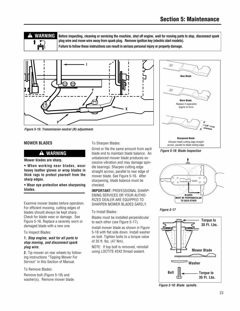
Examine mower blades before operation.For efficient mowing, cutting edges ofblades should always be kept sharp.Check for blade wear or damage. SeeFigure 5-16. Replace a severely worn ordamaged blade with a new one.
To Inspect Blades:1. Stop engine, wait for all parts tostop moving, and disconnect sparkplug wire.2. Tip mower on rear wheels by follow-ing instructions “Tipping Mower ForService” in this Section of Manual.
To Remove Blades:Remove bolt (Figure 5-18) andwasher(s). Remove mower blade.
To Sharpen Blades:Grind or file the same amount from eachblade end to maintain blade balance. Anunbalanced mower blade produces ex-cessive vibration and may damage spin-dle bearings. Sharpen cutting edgestraight across, parallel to rear edge ofmower blade. See Figure 5-16. Aftersharpening, blade balance must bechecked.IMPORTANT: PROFESSIONAL SHARP-ENING SERVICES OR YOUR AUTHO-RIZED DEALER ARE EQUIPPED TOSHARPEN MOWER BLADES SAFELY.
To Install Blades:Blades must be installed perpendicularto each other (see Figure 5-17).Install mower blade as shown in Figure5-18 with flat side down. Install washeron bolt. Tighten bolts to a torque valueof 35 ft. lbs. (47 Nm).NOTE: If top bolt is removed, reinstallusing LOCTITE #242 thread sealant.
Figure 5-15: Transmission neutral (N) adjustment.
P
I
X
Y
Mower blades are sharp.• When working near blades, wearheavy leather gloves or wrap blades inthick rags to protect yourself from thesharp edges.• Wear eye protection when sharpeningblades.
WARNINGFigure 5-16: Blade Inspection
Replace if separationbegins to form.
Sharpen blade cutting edge straight across, parallel to blade trailing edge.
Figure 5-17
BLADESMUST BE PERPENDICULAR
TO EACH OTHER
FRONT
Figure 5-18: Blade spindle.
Torque to35 Ft. Lbs.
Torque to35 Ft. Lbs.
Mower Blade
Washer
Bolt
Before inspecting, cleaning or servicing the machine, shut off engine, wait for moving parts to stop, disconnect sparkplug wire and move wire away from spark plug. Remove ignition key (electric start models).Failure to follow these instructions can result in serious personal injury or property damage.
WARNING
23

24
Section 5: Maintenance
BATTERY MAINTENANCE
Battery Care in Service
The battery is sealed and is mainte-nance-free. Acid levels cannot bechecked.• Always keep the battery cables and ter
minals clean and free of corrosive build-up.
• After cleaning the battery and termi-nals,
apply a light coat of petroleum jelly or grease to both terminals
• Always keep the rubber boot posi-tioned
over the positive terminal to prevent shorting.
ChargingIf the tractor has not been put into usefor an extended period of time, chargethe battery with an automotive-type 12-volt charger for a minimum of one hourat six amps.Jump StartingIMPORTANT: Never jump your tiller’sdead battery with the battery of a run-ning vehicle.
1. Connect end of one jumper cable tothe positive terminal of the good battery,then the other end to the positive termi-nal of the dead battery.2. Connect the other jumper cable to thenegative terminal of the good battery,then to the frame of the unit with thedead battery.
Failure to use this procedure couldcause sparking, and the gas in eitherbattery could explode.
CleaningClean the battery by removing it fromthe tractor and washing with a bakingsoda and water solution. If necessary,scrape the battery terminals with a wirebrush to remove deposits. Coat termi-nals and exposed wiring with grease orpetroleum jelly to prevent corrosion.Battery FailuresSome common causes for battery failureare: • incorrect initial activation• undercharging• overcharging• corroded connections• freezingIMPORTANT: These failures are NOTcovered by your tractor’s warranty.
Battery Removal and InstallationWhen removing and installing the bat-tery, disconnect and connect the cablesin this order to avoid sparking:1. To remove the battery, first discon-nect the negative (-) cable from thegrounding screw on the back of the bat-tery bracket post. Bend the cable awayfrom any metal parts.2. Disconnect the negative (-) cablefrom the negative (-) battery post.3. Disconnect the positive (+) cablefrom the positive (+) battery post andbend it away from any metal parts.Cover the cable terminal with its rubberboot.4. Remove the battery clamp.5. To install the battery, reverse theabove steps. Be sure that the batteryposts face to the rear of the tiller andthat the positive (+) post is on the leftside as you face forward from the han-dlebars.
Battery StorageCharge battery fully. The battery losessome of its charge each day when theunit is not used.IMPORTANT: NEVER store battery with-out a full charge. Recharge battery be-fore returning to service or every twomonths, whichever occurs first.When storing unit for extended periods,disconnect battery cables. Removingbattery from unit is recommended.
CLEANING UNDERSIDE OF MOWER DECK
Frequently check, and clean if necessary,the underside of the mower deck. Grassbuild-up in this area can affect the cut-ting performance. Before inspecting orcleaning, make sure that the engine isshut off and the spark plug wire is disconnected from the spark plug.
Inspection/Cleaning of Mower Deck:1. Stop engine, wait for all parts tostop moving, and disconnect sparkplug wire.2. Tip mower on rear wheels by follow-ing instructions "Tipping Mower ForService" in this Section.3. Use a plastic or metal scraper to remove grass build-up from deck orblades.
Mower blades are sharp.When working near blades, wearheavy leather gloves or wrap blades inthick rags to protect yourself from thesharp edges.
WARNING
Before inspecting, cleaning or servicing the machine, shut off engine, wait for moving parts to stop, disconnect sparkplug wire and move wire away from spark plug. Remove ignition key (electric start models).Failure to follow these instructions can result in serious personal injury or property damage.
WARNING
Use extreme caution when working onor near batteries. To help prevent per-sonal injury or property damage:.
• Batteries generate explosive gases.Keep sparks and flames away fromthe battery at all times. Ventilate thearea when charging or using the bat-tery in an enclosed area.
DANGER
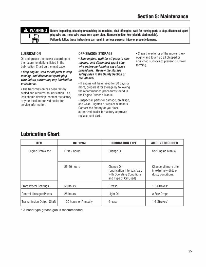
25
Section 5: Maintenance
Lubrication ChartLUBRICATION TYPE
Change Oil
Change Oil(Lubrication Intervals Varywith Operating Conditionsand Type of Oil Used)
Grease
Light Oil
Grease
ITEM
Engine Crankcase
Front Wheel Bearings
Control Linkages/Pivots
Transmission Output Shaft
INTERVAL
First 2 hours
25-50 hours
50 hours
25 hours
100 hours or Annually
AMOUNT REQUIRED
See Engine Manual
Change oil more oftenin extremely dirty ordusty conditions.
1-3 Strokes*
A Few Drops
1-3 Strokes*
* A hand-type grease gun is recommended.
Before inspecting, cleaning or servicing the machine, shut off engine, wait for moving parts to stop, disconnect sparkplug wire and move wire away from spark plug. Remove ignition key (electric start models).Failure to follow these instructions can result in serious personal injury or property damage.
WARNING
WARNING
LUBRICATIONOil and grease the mower according tothe recommendations listed in theLubrication Chart on the next page.
• Stop engine, wait for all parts to stopmoving, and disconnect spark plugwire before performing any lubrication procedures.
• The transmission has been factorysealed and requires no lubrication. If aleak should develop, contact the factoryor your local authorized dealer for service information.
OFF-SEASON STORAGE• Stop engine, wait for all parts to stopmoving, and disconnect spark plugwire before performing any storageprocedures. Review the storagesafety rules in the Safety Section ofthis Manual.
• If engine will be unused for 30 days ormore, prepare it for storage by followingthe recommended procedures found inthe Engine Owner's Manual.
• Inspect all parts for damage, breakage,and wear. Tighten or replace fasteners.Contact the factory or your local authorized dealer for factory-approvedreplacement parts.
• Clean the exterior of the mower thor-oughly and touch up all chipped orscratched surfaces to prevent rust fromforming.

26
Section 5: Maintenance
*Interval describes running time.
**A hand-type grease gun is recommended when greasing yourunit. High-pressure type grease guns could cause damage to fit-tings/seals.
***Consult engine manual for more detailed engine service infor-mation.
****Clean more often under dusty conditions or when airbornedebris is present. Replace air cleaner parts, if very dirty.
ATTENTION! This chart describes service guidelines only. It does not provide complete service information. Complete serviceis available from your authorized mower or engine dealer. Before performing any of the maintenance procedures, refer to theappropriate information contained in this Manual or the Engine Owner’s Manual for the correct safety precautions and mainte-nance procedures.
ITEM
Mower BladeLoose or Missing HardwareBeltsEngine Oil LevelControlsMulching Cover
Engine Oil
Engine Oil***Foam Air Filter****Mower Blade(s)Control Linkages and Pivots
Engine Oil***Blade Drive Belt AdjustEngine Cooling FinsGrease Fittings**
Air Filter Element****Spark PlugTransmission Output Shaft
LinkagesBelts
Front Wheel Bearings
SERVICE
As RequiredTighten or ReplaceCheckCheckCheck for Proper OperationCheck for Proper Cover Installation
Change
ChangeCleanSharpen and BalanceLube with Light Oil
ChangeAdjust TensionCleanGrease
ReplaceClean/Replace, Re-gapGrease
AdjustCheck/Replace, Adjust
Grease
Maintenance Chart INTERVAL*
Each use
1st 2 hours
25 hours
50 hours
Annually or 100 hours
Monthly
Annually or 50 hours
Before inspecting, cleaning or servicing the machine, shut off engine, wait for moving parts to stop, disconnect sparkplug wire and move wire away from spark plug. Remove ignition key (electric start models).Failure to follow these instructions can result in serious personal injury or property damage.
WARNING

27
Engi
ne d
oes
not t
urn
over
.
Engi
ne tu
rns
over
but
will
not
sta
rt.
Engi
ne s
tarts
onl
y af
ter r
epea
ted
tries
.
Engi
ne ru
ns ro
ughl
y.
Engi
ne s
talls
in a
few
sec
onds
.
Engi
ne ru
ns b
ut u
nit d
oes
not m
ove.
Whe
el d
rive
alw
ays
enga
ged.
Engi
ne s
talls
whe
n ho
t.
Engi
ne o
verh
eats
.
Engi
ne d
oes
not s
hut o
ff.
Blad
e dr
ive
inop
erat
ive.
Blad
e dr
ive
alw
ays
enga
ged.
Batte
ry n
ot c
harg
ing
(if a
pplic
able
).
Poor
mow
ing
perfo
rman
ce.
Blad
e do
es n
ot s
top
whe
n Op
erat
orPr
esen
ce C
ontro
l is
rele
ased
.
Exce
ssiv
e vi
brat
ion.
Engine malfunction (refer to engine manual). • • • • • • • • •Improperly adjusted drive linkage. • • • • • • •Dirty engine cooling fins or flywheel screen. •Faulty ignition. • • • • • • •Faulty spark plug. • • • • •Empty fuel tank. • • • •Battery or charging malfunction (if applicable). • • • •Improperly adjusted or dirty carburetor. • • • • •Improper oil level. • •Dirty air cleaner element. • • • •Improperly adjusted choke (if applicable). • • • • •Transmission malfunction. • •Improperly adjusted drive linkage. • • • • •Broken, loose or worn belt(s). • • • • • •Dull blade(s). • •Throttle control out of adjustment. • • •Blade/brake system out of adjustment. • • •Blade(s) out of balance. • •Loose hardware. • • •
Troubleshooting Chart
ATTENTION! This table describes serviceguidelines only. It does not provide com-plete service information. Complete serviceis available from your authorized mower orengine dealer. Before performing any of thecorrections in this table, refer to the appro-priate information contained in this Manualor the Engine Owner’s Manual for the cor-rect safety precautions and operating ormaintenance procedures.
Possible cause
Symptom
Section 5: Maintenance
Before inspecting, cleaning or servicing the machine, shut off engine, wait for moving parts to stop, disconnect sparkplug wire and move wire away from spark plug. Remove ignition key (electric start models).Failure to follow these instructions can result in serious personal injury or property damage.
WARNING

40
NOTES

41
NOTES

MANUFACTURER’S LIMITED WARRANTY FOR:
The limited warranty set forth below is given by Troy-Bilt LLC with respect to new merchandise purchased and used in the United States, its possessions and territories.
“Troy-Bilt” warrants this product against defects in material and workmanship for a period of two (2) years commencing on the date of original purchase and will, at its option, repair or replace, free of charge, any part found to be defective in materials or workmanship. This limited warranty shall only apply if this product has been operated and maintained in accordance with the Operator’s Manual furnished with the product, and has not been subject to misuse, abuse, commercial use, neglect, accident, improper maintenance, alteration, vandalism, theft, fire, water, or damage because of other peril or natural disaster. Damage resulting from the installation or use of any part, accessory or attachment not approved by Troy-Bilt for use with the product(s) covered by this manual will void your warranty as to any resulting damage.
Normal wear parts are warranted to be free from defects in material and workmanship for a period of thirty (30) days from the date of purchase. Normal wear parts include, but are not limited to items such as: batteries, belts, blades, blade adapters, grass bags, rider deck wheels, seats, snow thrower skid shoes, shave plates, auger spiral rubber and tires.
HOW TO OBTAIN SERVICE: Warranty service is available, WITH PROOF OF PURCHASE, through your local authorized service dealer. To locate the dealer in your area, check your Yellow Pages, or contact Troy-Bilt LLC at P.O. Box 361131, Cleveland, Ohio 44136-0019, or call 1-866-840-6483 or 1-330-558-7220, or log on to our Web site at www.troybilt.com.
This limited warranty does not provide coverage in the following cases:
a. The engine or component parts thereof. These items may carry a separate manufacturer’s warranty. Refer to applicable manufacturer’s warranty for terms and conditions.
b. Log splitter pumps, valves, and cylinders have a separate one year warranty.
c. Routine maintenance items such as lubricants, filters, blade sharpening, tune-ups, brake adjustments, clutch adjustments, deck adjustments, and normal deterioration of the exterior finish due to use or exposure.
d. Service completed by someone other than an authorized service dealer.
e. Troy-Bilt does not extend any warranty for products sold or exported outside of the United States, its possessions and territories, except those sold through Troy-Bilt’s authorized channels of export distribution.
f. Replacement parts that are not genuine Troy-Bilt parts.g. Transportation charges and service calls.
No implied warranty, including any implied warranty of merchantability of fitness for a particular purpose, applies after the applicable period of express written warranty above as to the parts as identified. No other express warranty, whether written or oral, except as mentioned above, given by any person or entity, including a dealer or retailer, with respect to any product, shall bind Troy-Bilt. During the period of the warranty, the exclusive remedy is repair or replacement of the product as set forth above.
The provisions as set forth in this warranty provide the sole and exclusive remedy arising from the sale. Troy-Bilt shall not be liable for incidental or consequential loss or damage including, without limitation, expenses incurred for substitute or replacement lawn care services or for rental expenses to temporarily replace a warranted product.
Some states do not allow the exclusion or limitation of incidental or consequential damages, or limitations on how long an implied warranty lasts, so the above exclusions or limitations may not apply to you.
In no event shall recovery of any kind be greater than the amount of the purchase price of the product sold. Alteration of safety features of the product shall void this warranty. You assume the risk and liability for loss, damage, or injury to you and your property and/or to others and their property arising out of the misuse or inability to use the product.
This limited warranty shall not extend to anyone other than the original purchaser or to the person for whom it was purchased as a gift.
HOW STATE LAW RELATES TO THIS WARRANTY: This limited warranty gives you specific legal rights, and you may also have other rights which vary from state to state.
IMPORTANT: Owner must present Original Proof of Purchase to obtain warranty coverage.
Troy-Bilt LLC, P.O. BOX 361131 CLEVELAND, OHIO 44136-0019; Phone: 1-866-840-6483, 1-330-558-7220