OPERATOR'S MANUAL - westerbeke.coms manual/33105_10-2-3.0... · Your new engine needs twenty hours...
38
OPERATOR'S MANUAL for tIIIEStERBEICE 1() TWO )\ MARINE ENGINE AND tIIIES.,.ERBEICE SlCtIII GENERATOR SET Publication Number 33105 Printed in U.S.A. J. H. WESTERBEKE CORP. AVON INDUSTRIAL PARK, AVON, MASS. 02322· {6f7} 588 7700 CABLE: WESTCORP, AVON· TELEX: 92 4444
Transcript of OPERATOR'S MANUAL - westerbeke.coms manual/33105_10-2-3.0... · Your new engine needs twenty hours...

OPERATOR'S MANUAL
for
tIIIEStERBEICE 1() TWO )\
MARINE ENGINE
AND
tIIIES.,.ERBEICE SlCtIII GENERATOR SET
Publication Number 33105 Printed in U.S.A.
J. H. WESTERBEKE CORP. AVON INDUSTRIAL PARK, AVON, MASS. 02322· {6f7} 588 7700
CABLE: WESTCORP, AVON· TELEX: 92 4444

~------
C.ALI IA

FOREWORD
Thank you for having selected a Westerbeke Diesel Engine for your use.
This manual describes the procedures for proper handling and maintenance of both:
(a) 10 Horsepower Marine Propulsion Engine
(b) 3 KW Marine Generator Set
To obtain best operating condition and longest life, it is important to use it sensibly and carry out operatiorl and maintenance according to this manual •.
If you have questions about your equipment or in the event of a failure, please contact your nearest distributor or dealer.
We look forward to your continued patronage.
1

TABLE OF CONTENTS PAGE
GENERAL SPECIFICATIONS ••••••••••.•••• 3
CAUTIONS IN HANDLING ENGINE •••••••••• 4
1 • B REA KIN GIN • • • • • • • .. • .. • • • 0 .. • • • • •• 5
2. PREPARATIONS ..................... 6
3. STARTING PROCEDURES •.••...•.•••• 7
4. STOPPING PROCEDURES .••••.••.•••• I0
5. CAUTIONS ON STARTING AND OPERATION ••• ". 0 •• co ......... 0 .. 10
6. REQUIREMENTS FOR PROPER OPERATION 6-1 Lubrication System •.•..•••. 12 6-2 Fuel System •.•••••••.•••••• 13 6-3 Cool System ..•••.••••••• 16 6-4 Wiring iagram~~ •••••.••..• 18 6 - 5 Bel t 'r ens ion. .. • " e _ • .. • • • .. • • .. 18 6-6 Domestic Hot Water .••••.•.• 18
7 RECOMfRIENDED MAINTENANCE SERVICE .19
8.. TRANSMISSIONS.. .. • • .. . ... ..., .............. 22
9. TROUBLESHOOTING ..... ~ 0 ••••••• 23
10 .. SERVICE DATA .................. " .. _ ...... 24
11 .. TABLE OF TIGHTENING TORQUES" ..• 24
12. INSTRUCTIONS: 3KW GENERATOR SET.25
14. STOPPING PROCEDUP~.e~o •••••••••• 28
15.. WIRING DIAGRAM ............ " ................... 29
17 .. EXPLODED VIEW GENERA fI 10R PORTION .. 30
18 .. GENERAL INFORMATION ELECTRICAL •• 31
19.. MAl NlfENANCE .. " ............ " ........ II ........ ,,32
20. INTERNAL WIRING DIAGRAM .......... 33
21. LIMITED WARRANTY •••••••••.•.•.•• 34
2

GENERAL SPECIFICATIONS
ENGINE
Type Vertical 4 cycle, water cooled
No. of cylinders Two
Bore & stroke (inches) 2.56 X 2.68
Cubic inch displacement 27.52
Compression ratio 25:1
Firing order 1-2
Dry weight, engine only 128 pounds
Injection pump Bosch type
Injectors Throttle type
Combustion chamber Swirl type
Fuel #2 diesel
Governor Centrifugal weight type
Lubrication system Pressure by trochoid pump
Oil filter Paper type, engine mounted
Engine oil capacity 2 quarts
Cooling system Forced circulation through heat exchanger
Electric starter 12 volt, 1 horsepower
Alternator 35 ampere, 12 volt
Glow plugs Sheathed quick heat type
Battery capacity Recommend 60 amp hour
Generator type
Insulation
GENERATOR
4 pole, revolving regulated, self excited, AC slip design
Class F
3
armature, inherently limiting, rectifier
rings, single bearing

INSTALLATION AND SUPPLY CAUTIONS
* Check important aspects of installation before operating engine .
(1) Alignment (Error to be no more than one thousandth of an inch per inch of coupling diameter)
(2) Provide sufficient ventilation
(3) Provide around clauses)
adequate service room engine (See warranty
. 003 FEELER GAGE
CHECKING COUPLING ALIGNMENT
* Fill fuel tank with CLEAN #2 diesel from a reputable manufacturer.
* Fill lubricating oil to full mark on dipstick (Select readily available lubricating oil of grade CC or CD).
* Fill water with suitable mixture of water and antifreeze to suit your temperature zone. See page 16.
* Plug-in Panel Harness Connection. After assembly, joint should be taped to prevent corrosion or, preferably, assembled using a silicon grease which can be obtained at an electronic store such as Radio Shack.
SAFETY PRECAUTIONS
*
*
*
*
Never operate engine with inadequate ventilation.
Do not touch moving parts during operation.
Do not touch hot parts such as exhaust pipe, and do not place combustible materials near.
Inspect and adjust parts of the engine only after it is stopped.
* Check and refill engine oil, cooling water and fuel after the engine is brought to a stop.
* In checking the water level for refilling, remove the pressure cap only after the water temperature has fallen enough to prevent a steam burn.
* Always use tools that fit cor rectly and use caution dur ing servicing.
* Be sure that current carrying wires are protected from abrasion and that all connections are tight.
4

BREAKING IN YOUR NEW ENGINE
While your engine has had individual test operations sufficient to demonstrate accurate assembly and correct operation of all systems, it still requires break in time~
Service life of your engine is dependent on how your engine is operated and serviced during the initial twenty hours of operation.
Your new engine needs twenty hours of conditioning operation for breaking in each moving part, thus maximizing performance and life of eng Ine. Perform this condi tioning carefully, keeping the following points in mind.
1. Start engine, run idle while checking that all systems are functioning - sea water pump, oil pressure, battery charge.
2. Warm eng ine, preferably by running propeller at fast idle while tied down, until water temperature gauge moves into the 130 - 140 degree range.
3. Then use engine at moderate load (60% ±) for first five hours.
4. Avoid rapid acceleration.
5. Use caution not to overload engine. Grey or black smoke is a sign of overload.
6. Next fifteen hours may be run at 70 - 75% load.
Explanation:
"Breaking in" a new en~ine is basically a seating of the piston rings to the cylinder walls. This is not accomplished by long per iods of runnIng idle, nor by early running under full load, nor by varying loads with intervals of fast acceleration and/or excessive speed.
Idle running may glaze the cylinder walls causing oil consumption and smoky operation. Excessive speeds and loads may score cylinder walls with similar results.
As indicated above, use a short warm up at idle and put engine under moderate load and speed for the first five hours of operationo For the next fifteen hours, use approximately 70% load. 'rhis kind of careful operation will result in best results from your engine&
5

PREPARATIONS
Take steps as shown below in starting your engine for the first time or after a prolonged shut-down.
1. Fill your engine with oil up to or near the upper limit on the dipstick. Use a good grade of oil with API specification of CC or better. For quantity of oil, you may refer to the General Specifications page. However, it is best always to be guided by dipstick measurement as angle of installation has some effect.
2. Your engine is supplied with a coolant recovery system to which the following instructions apply:
a) Fill engine completely to the neck of the manifold cap.
b) Then fill the recovery tank to the bottom level line. Need for adding coolant is indicated when a cold engine has coolant level below the bottom level line.
c) In winter add antifreeze as described on page 16. Antifreeze may be used year round if changed annually.
3. Fill the fuel tank with Diesel fuel. The interior of the fuel tank must be maintained clean. Be careful not to allow introduction of dirt when filling fuel ..
4 • Engine oil, coolant transmission levels should checked at least once a prior to engine use.
and be
day
6
011 filler port

STARTING PROCEDURES
Instrument panel, description and use of:
...... "'"
Note 1: When engine is stopped after use, the water temperature and oil pressure gauges may stay at their running readings.
Note 2: When eng ine is next to be used, turn start swi tch to "ON". The temperature and pressure gauges will "ZERO" and the voltmeter will register battery voltage. The electric fuel pump, mounted on the engine, will also begin to operate, purging any air accumulated in the system.
Note 3: The engine is now prepared for starting.
7

STARTING PROCEDURES
1. Turn the starter switch to the liON" posi tiona If making an ini tial start after lay-up, fuel filter servicing or repairs, allow fuel pump to work lS-2S seconds to purge the system of any air. Check that clutch is in neutral and that throttle is in full forward.
2. Glow plug preheating
with key in 1I0N II position, push in about 1/4 inch or enough so that voltmeter indicates discharge. Hold key in depressed posi tion until glow plugs are sufficiently hot. Follow Table below for preheating time.
Quick-heat type (Yl14T)
Atmospheric temperature
+S-C (+41-F) or higher
+S-C (+41-F) to -S-C (+23-F)
-S·C (+23-F) or lower
Limit of continuous use
3_ Proper glow plug function is indicated by vol tmeter drop when key is depressed _ This drop will be slight but discernible_ If no voltage drop is noted, it may indicate defecti ve glow plugs or a faulty preheat circuit (check for loose connection).
8
Preheating
Approx. 10
Approx. 20
Approx. 30
1 minute
time
sec.
sec.
sec ..

4. Starting
Continuing to hold the key depressed, turn to the "START" position. The starter motor will run thereby cranking the engine. Hold throttle open until engine runs and then reduce throttle.
Should the engine not start even when the starter switch is left at "s" position for 10 seconds, take your hand off the starter switch for 30 seconds, and then attempt to start the engine again by sufficiently preheating the glow plug. The starter motor should never be allowed to run for more than 30 seconds at a time.
5. Operation
As soon as the engine has star ted, release the key. The key will automatically return to the "ON" posi tiona Leave the key at "ON" dur ing oper ation. Check that wi th eng ine running, oil pressure and battery charge voltage are registering and that raw water is discharging with the exhaust.
During engine operation, do not turn the key to "s" position. may damage the starter motor.
6. Warm-up operation
Run a few minutes at "IDLE" position to assure that all functions are operating. Then operate under reduced load until water temperature rises into the 140-150· range.
9
This

STOPPING PROCEDURE
1. Stop
To stop the engine move the throttle control through the idle position to stop. As the throttle is moved past idle there will be increased resistance to movement because a spring loading must be overcome. Hold the throttle firmly against the pressure until the engine comes to a complete stop.
2. Starter switch off
Wi th the eng ine stopped, turn the starter key back to "OFF" position. The battery will be discharged if the key is left at "ON" position. An engine alarm buzzer is provided to warn the operator of this possibility. Best precaution is always to remove the key.
CAUTIONS ON STARTING AND OPERATION
1. Normal starting
Follow the procedures below for routine starting of your engine.
I} Check the engine and transmission oil levels and refill if necessary.
2} Insure that you have sufficient fuel. Keep tank as full as possible.
3} Check cooling water level, and refill if necessary~ Note: Check for leaks of water or oil, particularly \-lhen signs of such leak are found on the bottom of the e~gine or in the drip tray.
4) Start the engine in accordance with the procedures given on the preceding pages.
5} Allow the engine to warm up to 140·-150· F before placing the engine under heavy load.
2. Starting under cold conditions
The following three adverse conditions concur as the atmospheric temperature drops exceedingly, and the engine must, under such conditions, be started by taking steps described below:
LUBRICATING OIL TURNS VISCOUS Make certain that viscosity is proper for the prevailing atmospheric temperature. Check the oil also for deterioration. (Study page 12.)
10

VOLTAGE ACROSS BATTERY TERMINALS DROPS battery is fully charged.
Check that the
THE TEMPERATURE OF INTAKE AIR IS LOW AND COMPRESSION TEMPERATURE DOES NOT RISE ENOUGH Allow the glow plug to operate sufficiently to aid starting. See table on page 8.
3. Cautions during operation
Confirm that the oil pressure is normal during normal operation.
Confirm that exhaust gas is as follows:
* * *
While engine is cold ....•..•.•.•.••..•... White smoke When the engine grows warm ...•..•.....•.. Almost smokeless When the engine is overloaded .....•..•... Some black smoke
Check for abnormal noise such as knocking, fr iction or leaking sounds, and vibration and blow-back sounds.
Check for leaks of fuel and engine oil.
A knocking sound is heard while the engine is cold, during quick acceleration and at idle. Confirm that no knocking sound is heard in other cases.
Photo above is right hand side of WlOtwo wi th 2: 1 reverse and reduction gear. Note convenient cable attachment brackets for clutch and throttle, accessible filter location and lube oil drain hose.
11

REQUIREMENTS FOR PROPER OPERATION
LUBRICATION SYSTEM
1. Engine oil
For engine lubrication, use diesel engine oil. Diesel engine oils are classified according to the API Specifications into grades CA, CB, CC and CD. Anyone of them is usable, but use of CC or higher grades prepared by well-known makers is recommended.
2. Engine oil viscosity
Use oil having viscosity best suited to the atmospheric temperature. Use of an all-season oil SAEIOW-30 with minimum viscosity change under different temperatures is suggested.
20·C (6S·F) or higher SAE 30 or 1~W-30
SAE 20 or 10W-30
S·C (41·F) or lower SAE IOW-30
3. Oil pressure
The oil pressure during operation of the engine is indicated by the oil pressure gauge.
During normal operation ....•.•..... Oil pressure will range between 50 and 70 PSI.
At the time of cranking •........•.. Pressure will rise proportionately with speed.
4. Engine oil change
To renew engine oil, discharge old oil through the sump drain hose attached at front of engine while engine is still warm. Drain old oil completely, replace the hose, plug the end securely and add fresh oil through the oil inlet port on the valve cover. After refilling oil, idle the engine for several minutes and stop. Then check the quantity of oil by the oil level gauge. Fill to but not over the high mark on the dipstick. Always observe old oil as it is removed. A yellow/grey emulsion indicates presence of water in the oil. While this condition is rare, it does require prompt attention to prevent serious damage.
12

5. Replacement of oil filter
Being a replaceable cartridge type, the oil fil ter requires no cleaning inside. In installing the oil filter, apply eng ine oil th inly on to the O-ring, and then tighten it by hand firmly.
When removing the used fil ter , cover over with a plastic bag. This will allow both filter element and spilled oil to be collected cleanly without spilling oil in the bilge.
Note A:
Note B:
After market filters are not recommended since the material standard or diameters of important items might be entirely different from genuine parts.
Immediately after filter change and oil fill, run engine to ensure that oil pressure is normal and that there are no oil leaks.
FUEL SYSTEM
1. Diesel fuel
2.
USE #2 DIESEL FUEL. NEVER USE KEROSENE OR HEAVY OIL.
In cold weather particularly, water vapor is produced by condensation when air is present in the fuel tank. The tank, therefore, should be kept full as much as possible.
The fuel tank, furthermore, needs to be kept completely free of dirt and water.
It is required that a primary fuel filter of the water entrapment type be installed betvleen the fuel tank and the eng ine. Such a fil ter, shovln her e, is avail able under Par t #32974 from your local Wester beke representati ve or your boat builder. rrhis filter, adapted for boat builder use, comes complete wi th fi ttings for either hose or metal tubing~ Mount in an accessible place, inspect often and drain off water accumulation fre~
quently ..
13
WATER LEVEI, INDICATOR---~" .. ,,,,,~-,,-,,,,,,,,,-,,,-,,,-,,-
RING

3. Notes on fuel system
See on facing page a typical explode~ view of a fuel system for a two cylinder engine. It is also illustrative of the self-bleeding system used on the Westerbeke 3 KW marine generator set.
The Westerbeke self-bleeding fuel system is automatic in operation. While it is unlikely that the operator will be forced to service the system at sea, the possibility does exist. Therefore, it is recommended that the following parts be carried onboard.
Banjo washers #'s 11, 30, 31, 33, 34, 45 Injector seat washers #42 Lift pump filter and gaskets #'s 6, 7, 8 Fuel filter element and gaskets #'s 13, 14 ,15
I f a leak should develop at a banjo or washer that cannot be remedied by a simple tightening of the screw, renew the washers.
The engine can be started by taking the steps described on pages 8 and 9. In cases where the engine cannot be started easily, loosen two injection nuts on the nozzle side, turn the speed control lever to "full open" position, turn the starter motor and then tighten the nuts firmly.
4. Cleaning fuel filter and replacing filter element
After the first 50 hours of operation, loosen the retainer ring #16 and discard filter element #15. Clean bowl #17 and re-install new filter, using new gasket #13 and #14.
This same treatment is required of the filter element #6 in the fuel lift pump. Similarly, replace new filter element #6 using new gasket #7 and #8.
After the first 50 hour change, the change period may be increased to 200 hours or once per season.
5. Fuel injection pump
The fuel injection pump is one of the most important components of the diesel engine and thus it calls for the ,utmost caution in handling. Furthermore, the fuel injection pump has been thoroughly shop-adjusted and should never be readjusted carelessly. Such adj ustment, whenever necessary, should be per formed at an authorized service station, as a precision pump tester and skills are required.
To obtain long and satisfactory use of your injection pump:
Always use fuel which is free from impurities. Clean and renew the fuel filter periodically. Inspect water entrapment filter regularly.
14

If a water trap type filter (see page 13) is not interposed between the fuel tank and engine lift pump, any entrained water will tend to lay in bottom of lift pump. Internal metal parts of the lift pump will rust. Particles will pass on to filters and eventually to injection pump and injectors with damaging and expensive results.
While many boat builders do supply a water trap filter, there are some who do not. It is to prevent such omission that Westerbeke offers a sedimenter/water trap filter as a desirable optional extra at moderate cost. It is supplied with fittings for either hose piping or metal tube piping.
Order it wi th the eng ine, install it in an accessible place, inspect it daily and drain as needed.
15

10 Cooling water
As cooling water, use soft water with least impurity content such as tap water (potable water) or rainwater, and never use hard water or foul water~ Use of hard water or water containing much impurity will lead to collection of scale in the engine and heat exchanger with resultant decline in cooling effects.
2.. Antifreeze
In cold districts, care should be taken to prevent cooling water from freezing" Cooling water, 'itlhen frozen, expands to break the heat exchanger and the cylinder block f and it is essential that antifreeze be added to cooling water in a quantity proportional to the lUvlest temperature of the dist.rict.. It is recommended that the antifreeze mixture be used throughout the yearo
*Antifreeze of poor quality or without rust inhibitor will cause corrosion of the cooling system. Always use antifreeze prepared by a reliable maker, and never use it mixed with antifreeze of a different brand.
*Make sure that the cooling system of the engi.ne is cleaned well before adding antifreeze~
*Recommended antifreeze for. year round use is ZEREX or PRE;STONE vIi th rust inhibi tor"
ANTIFREEZE ADDITION DATA
Antifreeze Concentration % 13 23 30 35 45 50 60 --~--"""":"~-~""'-~."""~"""""-"-""~-~'''''''.'''~---''~'.'~-'
Freezing .. c -5 -10 -15 -20 -30 -40 -50 t e.~.E.~E_a t ~ r. E: C' F) (23) (14) ( 5.) (-4) (-22) (-40) (-58)
Note: It is advisa.ble that antifreeze concen"tration be selected on the basis of a temperature which is about 5«C (106F) lower than the actual atmospheric tempera.ture expected ..
3. Fresh water cooling system
The system consists of a sea water pump which pumps raw sea water through a heat exchanger to remove heat from the coolant. The raw water is discharged overboard through the exhaust line$
The engine coolant (fresh water with or without antifreeze) is circulated by the fresh water pump in continuous circuit., pumped through the cylinder block, cylinder head, heat exchanger and back to the fresh water pump.
16

The total system is very reliable and requires only a daily check of the water level in the system plus routine check of hose clamps and fittings.
It is likely that zinc electrodes will waste away from contact with sea water. It is also possible for the raw water pump impeller to fail due to lack of sea water or deter ioration.. An early sign of impeller failure is less water and more steam at the exhaust through hull fitting.
It is recommended, therefore, that zinc electrodes #11885, water pump belt #32942, alternator belt #13585, sea water pump assembly #32617 and sea water impeller kit #32620 be carried onboard at all times.. These parts should be ordered from your nearest stocking dealer and used as inspection dictates ..
17
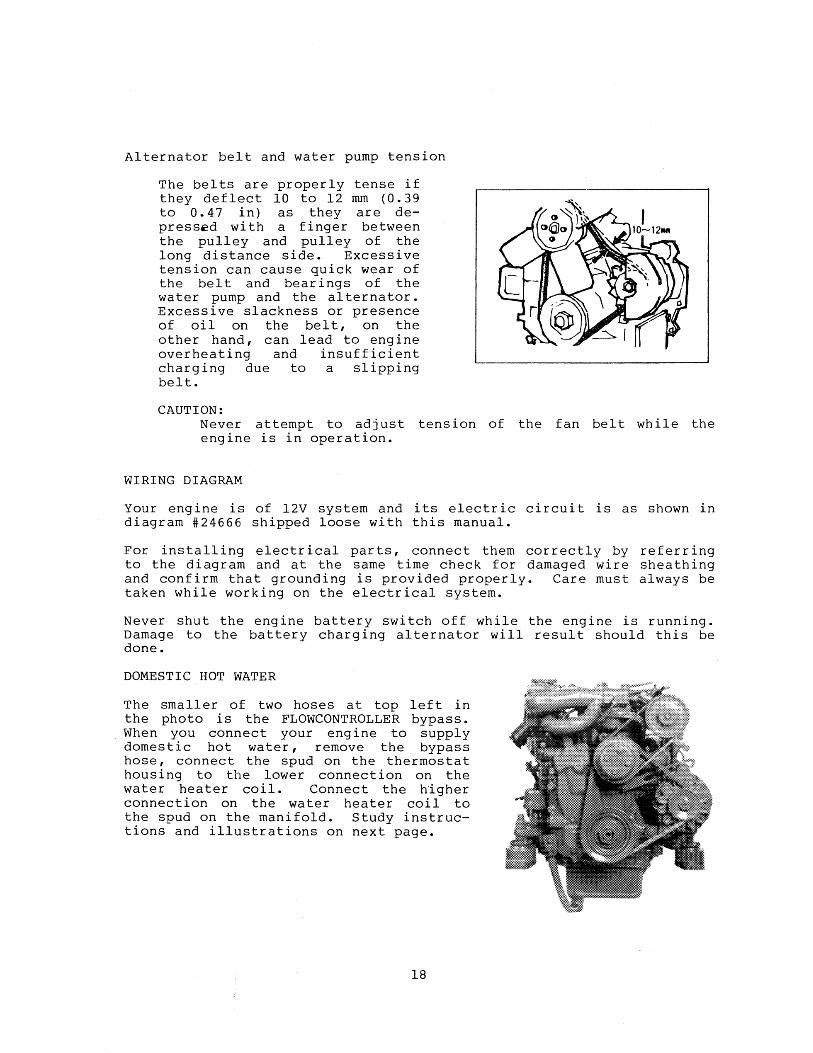
Alternator belt and water pump tension
The belts are properly tense if they deflect 10 to 12 mm (0.39 to 0.47 in) as they are depressed wi th a finger between the pulley and pulley of the long distance side. Excessi ve tension can cause quick wear of the belt and bearings of the water pump and the al ternator. Excessive slackness or presence of oil on the belt, on the other hand, can lead to engine overheating and insufficient charging due to a slipping belt.
CAUTION: Never attempt to adjust tension of the fan belt while the engine is in operation.
WIRING DIAGRAM
Your engine is of 12V system and its electric circuit is as shown in diagram #24666 shipped loose with this manual.
For installing electrical parts, connect them correctly by referring to the diagram and at the same time check for damaged wire sheathing and confirm that grounding is provided properly. Care must always be taken while working on the electrical system.
Never shut the engine battery switch off while the engine is running. Damage to the battery charging alternator will result should this be done.
DOMESTIC HOT WATER
The smaller of two hoses at top left in the photo is the FLOWCONTROLLER bypass. When you connect your eng ine to supply domestic hot water, remove the bypass hose, connect the spud on the thermostat housing to the lower connection on the water heater coil. Connect the higher connection on the water heater coil to the spud on the manifold. Study instructions and illustrations on next page.
18

Model WlOtwo comes complete with FLOWCONTROLLER which, when properly connected to a heater tank, produces domestic hot water from waste engine heat.
principle: There are two 7/8" hose connections at front of the engine which provide a parallel flow of engine cooling water to and from the heater. These connections are part of the FLOWCONTROLLER which assures a flow of hot water through the heater at all times and yet precludes excessive restriction of engine cooling water flow caused by the heater - all simply and automatically.
Installation: Remove the hose connecting the 7/8" spuds on front of engine as shipped from the factory (see illustration preceding page). Connect these spuds to the heater with 7/8" ID wire inserted hose. The spud on thermostat housing is the flow FROM the engine and should connect to lower fitting on heater. The spud on manifold is the flow RETURNING to the engine and should connect to the upper connection on heater.
Hoses should rise continuously from their low point at the heater to the engine so that trapped air will rise naturally from the heater to the engine. If trapped air can rise to the heater, then an air bleed petcock must be installed at the higher fitting on the heater for bleeding air while filling the system. Avoid loops in hose runs which will trap air.
If any portion of the engine cooling water circuit to or from the heater rises above the engine's own pressure cap, then the pressurized remote expansion tank must be installed in the circuit to become the highest point. The tank kit Part Number is 24177. Install the remote expansion tank in a convenient location such as a sail locker for ease of checking fresh water coolant level.
The cap on the engine mounted expansion tank/manifold should not be opened once the remote system is installed and filled.
The hose connection from the heater to the remote expansion tank should be routed and supported so as to rise continuously from the heater to the tank enabling any air in the system to rise.
Illustrations below are of FLOWCONTROLLER adapted to our two pass manifolds. While on Model WlOtwo the appearance is different, the principle is the same.
IIetlter Below Egine:
fieZlter Ab::JveEngiJ1tZ:
19

RECOMMENDED MAINTENANCE SERVICE
Check and service your engine at specified intervals to maintain it in its best conditions and permit it to perform as it should. As for those asterisked items, it is suggested that you have them performed by an authorized distributor or dealer.
1. Daily inspection before use
A. Checkup of engine oil level and refilling
No ref ill is required if the level is near the upper limi t line of the gauge.
B. Checkup of cooling water and refilling
Refill up to the filler cap neck.
C. Check your fuel supply
D. Checkup of gauges and meters
After starting your engine, check oil pressure, water temperature and voltage reading.
E. Checkup for loose parts (fan belt or bolt, etc.), damage and leaks
F. Checkup for abnormality with exhaust gas, noise and vibration
2. Servicing following initial 50 hours of operation
A. Renewal of engine oil
B. Replacement of oil filter
C. Renewal of cooling water
D. Adjustment of valve clearance (See SERVICE DATA)
*E. Tightening of bolts and nuts
*F. Adjustment of engine idle
3. Servicing at every 100 hours of operation
A. Renewal of engine oil
B. Replacement of oil filter
C. Cleaning of fuel filter
20

D. Adjustment of engine idle
4. Servicing at every 200 hours of operation
A. Replacement of engine mounted fuel filter elements
B. Replacement of fuel filter (cartridge type)
5. Servicing at every 400 hours of operation
A. Cleaning of fuel tank
*B. Adjustment of valve clearance
*C~ Checkup of starter motor, alternator and regulator
Check the brush and surface of commutator for the degree of wear. Replace the brush if it is r.vorn beyond the limi ts of wear.
*D. Checkup of glow plugs
Check the glow plugs for blow-out.
E. Removal of cooling water and flushing is suggested~
6. Servicing at every 800 hours of operation
*A. Checkup of nozzles
Set the injection starting +142
pressure to 1707 -0 psi and eliminate undesirable injection conditions including "after dripping"~
*B. Checkup of compression pressure
GOOD
Remove each glow plug and check cylinders, one by one, using a compresslom pressure gauge!.. If the pressu:ce differs by more than 2.5 kg/cm 2 (35 .. 6 psi) between cylinders or if the cylinder pressure is less than 32 kg/cm 2 (455.0 psi) at 320 RPM, correct it.
*Co Fuel injection adjustment
In case of severe vibration during idling, have it repaired at an authorized distributor or dealer which is equipped with a pump tester ..
21

*D. Checkup of alternator and regulator
Regulate the voltage and current by use of a circuit tester.
*E. Checkup of starter motor pinion and flywheel ring gear
Rectify the chamfered area that has been severely damaged by use of an oil stone or some pencil grinder, and replace the part if it is damaged allover.
*F. Tightening of bolts and nuts
TRANSMISSIONS
Westerbeke Model 10two may be supplied with standard transmission BW-3 and 2:1 RG or optional HBW-50 either 2:1 or 2.7:1 RG, also optional HBW-150 V-drive 1.8, 2.1, or 3:1 RG.
All All All BW All not
models turn right hand propellers. models have their own oil sumps and HBW models use ATF lubricant.
dipsticks.
units ,may use either ATF or 30 weight engine oil. models should be dumped into gear in one swift motion -allowed to slip in slowly.
The transmissions, their dipsticks and markings are illustrated in the sketches below. For dipsticks that are threaded in the case, measure oil by dropping dipstick on the case. Do not screw in.
Hm~ 150 V
22

TROUBLESHOOTING
1. ENGINE DOES NOT START
a. b.
c.
d. e. f.
g. h.
Starting switch is defective Deficient drive torque of the starter motor
Improper viscosity of engine oil Engine too cold Seizure of moving parts Air present in fuel system
No fuel in fuel tank Fuel filter clogged
Correct connections and contacts The battery is exhausted, trouble with the starter motor, or dirty or loose wiring Check the viscosity and renew oil if necessary Use glowplug starting aid Rectify Purge thoroughly with electric fuel pump Refill Clean or renew
2. ENGINE STALLS WHILE IN OPERATION
a. Fuel tank is empty b. Fuel filter clogged c. Air present in fuel system
3. IMPROPER OIL PRESSURE
a. Oil shortage b. Oil leak through connections c. Oil pressure switch
defective
4. ENGINE OVERHEATING
a. Cooling water shortage b. Water leaks c. Belt loose or smeared with
oil d. Raw water pump defective
5. BATTERY IS UNDERCHARGED
a. Belt tension improper b. Faulty wiring circuit c. Alternator not functioning
(observe voltmeter) d. Battery faulty e. Faulty voltage regulator
Refill Clean or renew Retighten fuel line connections to allow electric fuel pump to run long enough to purge air thoroughly
Refill Repair Replace
Refill Repair Clean or renew
Repair or renew
Rectify Rectify Replace
Replace Repair or renew
23

SERVICE DATA
1. Valve clearance (engine cold) 0.25 mm (0.010 in.) (both intake and exhaust)
2. Compression pressure
WlOtwo and 3 KW
3. Engine oil capacity (including oil filter)
4. Firing order
32 kg/cm 2 at 320 RPM (455 lbs/sq in)
2-1/2 quarts approximately (Go by dipstick.)
1 - 2
5. Injection timing - BTDC of compression stroke when started at smoke set positione
Marine Engine Generator
6.. Injection starting pressure
7. Cooling water capacity (in engine body alone)
TIGHTENING TORQUES
1 .. Cylinder head bolt (M8)
2 .. Rocker cover nut U18 )
3. Connecting rod cap nut
4. Flywheel bolt (MIO)
5. Crankshaft pulley nut (M24 )
6,. Oil drain plug
7 .. Oil filter
8. Nozzle holder
9 .. Nozzle holder & retaini.ng nut
25" before top dead center 25" before top dead center
+142 1707 0 psi
3 quarts approximately
3 .. 5 - 4.0 kg-m (25.3 - 28.9 lb-ft)
0 .. 5 - 0/7 kg-m (3.6 - 5.1 Ib-ft)
302 - 3 .. 5 kg-m (23.1 - 25.3 Ib-ft)
6.5 - 7.0 kg-m (47 .. 0 - 50/6 Ib-ft)
15 - 20 kg-m (108 .. 5 - 144 .. 7 Ib-ft)
5 .. 0 - 6.0 kg-m (36.2 - 43.4 Ib-ft)
101 - 1.3 kg-m (7 • 96 - 9.40 Ib-ft)
5.0 - 6.0 kg-m (36.2 - 43.4 Ib-ft)
6,,0 - 800 kg-m (43.4 - 57.9 Ib-ft)
24

INSTRUCTIONS FOR 3 KW GENERATOR SET
Instructions for the engine portion are generally the same as for the propulsion unit WlOtwo. The differences will be described in the following pages.
BREAKING IN
Service life of your generator is dependent upon how the engine is operated and serviced during the initial 10 hours of operation!
Your new engine needs at least 10 hours of conditioning operation for breaking each moving part in and maximizing performance and life of engine. Perform this conditioning carefully, bearing the following points in mind:
1. Since generator sets operate at 1800 current, your control of the breaking control of load.
RPM to obtain 60 cycle in process is limi ted to
2. Do not ever attempt to BREAK IN your generator set by running at NO LOAD.
3. Immediately on starting the set, add approximately 25% load to cause a fast warm up.
4. For the first 10 hours of operation, run between 20 and 60 percent load.
5. After 10 hours, you may load as needed, except that:
6. You must avoid overload at all times. Overload is signalled by smoky exhaust and/or a reduction in speed and voltage.
Explanation:
"Breaking in" a new engine is basically a seating of the piston rings to the cylinder walls. This is not accomplished by long per iods of running idle, nor by early running under full load.
Idle running may glaze the cylinder walls causing oil consumption and smoky operation. Excessive loads may score cylinder walls with similar results.
As indicated above, use a short warm up period under moderate load for the first ten hours of operation. For the next forty hours, use approximately 70% load. This kind of careful operation will result in best results from your engine.
25

STARTING PROCEDURES
Instrument panel, description and use of:
Note 1: When generator is stopped after use, the water temperature and oil pressure gauges may stay at their running readings.
Note 2: When generator is next to be used, depress preheat switch. The temperature and pressure gauges will "ZERO" and the voltmeter will register battery voltage. The electric fuel pump, mounted on the engine, will also begin to operate, purging any air accumulated in the system.
Note 3: The generator is now prepared for starting. for specific instructions.
26
See next page

STARTING PROCEDURES
1. If making an initial start after lay-up, fuel filter servicing or repairs, depress the preheat switch for 15 to 25 seconds. This will energ ize the fuel pump allowing it to purge the system of any accumulated air_ This will preheat the glow plugs at the same time. (See table below for preheating time. )
Quick-heat type (Yll4T)
Atmospheric temperature
+S·C (+4l-F) or higher
+S·C (+4l-F) to -S·C (+23-F)
-S·C (+23·F) or lower
Limit of continuous use
2. Proper glow plug function is indicated by voltmeter drop when key is depressed. This drop will be slight but dis-cernible. If no voltage drop is noted, it may indicate defective glow plugs or a faulty preheat circuit (check for loose connection).
3. The start wiring is designed so that the preheat switch must be depressed before the start switch will function.
27
Preheating
Approx. 10
Approx. 20
Approx. 30
1 minute
'.,
time
sec_
sec.
sec.
.''''":

4. Starting
While still holding preheat switch depressed, depress the start switch. The starter motor will run thereby cranking the eng ine. As soon as the eng ine runs, release the start switch which will return to its normally open posi tion. Continue holding the preheat switch depressed for 2 or 3 seconds. This defeats the low oil pressure shutdown until the engine oil pressure rises to normal running pressure. Now release the preheat switch.
PREHEAT START
STOP
~
Should the engine not start when start switch is depressed for 10 to 12 seconds, wait 30 seconds and repeat "3" with adequate preheat time. Never run the starter motor for more than 30 seconds at a time.
5. Operation
With the engine running, check that oil pressure and battery charge voltage are registering and that raw water is discharging with the exhaust. During engine operation, do not depress start switch as this will damage starter motor.
6. Warm-up operation
Operate at reduced load until water temperature rises to the 140 to 150 degree range.
STOPPING PROCEDURE
1. Stop
To stop the generator, depress the stop switch until engine stops completely and then release.
28
PREHEAT START
STOP
~ J

WIRING DIAGRAM FOR 3 KW GENERATOR SET
Your engine is of 12V system and its electric circuit is as shown on wiring diagram #24700 as shipped loose with this manual.
For installing electrical parts, connect them correctly by referring to the diagram and at the same time check for damaged wire sheathing and confirm that grounding is provided properly. Care must always be taken while working on the electrical system.
Never shut the engine battery switch off while the engine is running. Damage to the battery charging alternator will result should this be done.
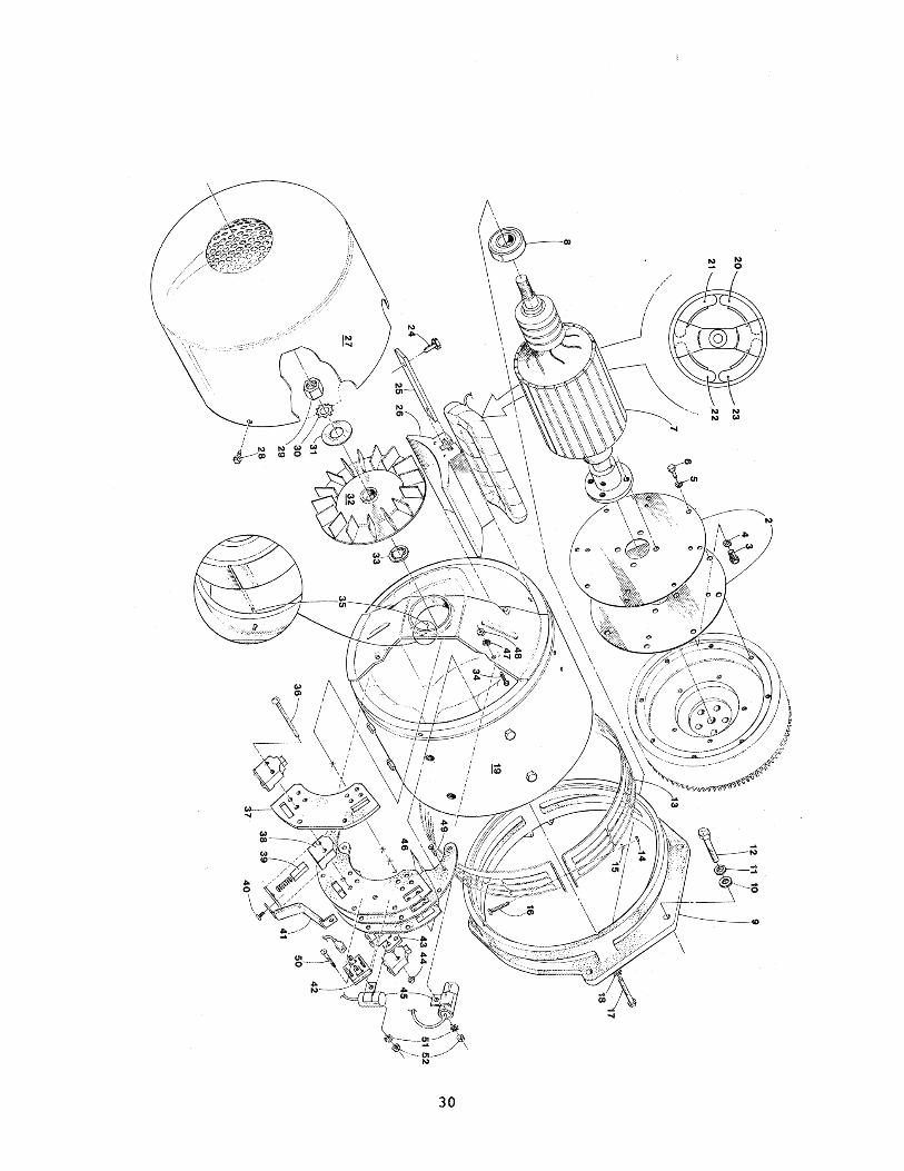
GENERATOR COMPONENT OF GENERATOR SET
All generators for the inherently regulated series are identical in design and alike except for length of the various sizes.
Wearing and replaceable parts are similar throughout. Brushes (39), bearings (8), rectifier (42), capacitor (45) all bear a high degree of commonali ty. (See next page.)
It is necessary only to give correct model and serial number to obtain correct parts from your local Dealer or Distributor.
Occasionally when a generator set is started, there will be no voltage build-up. When this occurs, the fields must be flashed to restore residual magnetism. The fields may be flashed wi th a 6 or 12 vol t battery as follows:
Stop the engine; remove the gener a tor end cover. You will notice the positive (+) lead from the field coil is connected to the + terminal of the rectifier (Part 42, opposite page), the negative lead from the field coil is connected to the opposite negative unmarked terminal of the rectifier. Using alligator clips, connect field coil posi ti ve to battery positive and field coil negative to battery negative for approximately ten seconds. The set will then build voltage and output. (Be careful not to connect on the AC terminals as this will destroy the rectifier.)
Annature
29
AC
+
Field Excitation Rectifier
30

GENERAL INFORMATION AND CARE OF GENERATORS
1. Use of Electric Motors
The power required to start an electr ic motor is considerably more than is required for keeping it running after it 1S once started. Some motors require much more current to start them than others. Split phase (A.C.) motors require more current to start them, under similar circumstances, than other types. They are commonly used on easy starting loads, such as washing machines or where loads are applied after the motor is started such as small power tools. Since they require 5 to 7 times as much current to start as to run, their use should be avoided whenever possible if the electric motor is to be driven by a small generator. Capacitor and repulsion-induction motors require from 2 to 4 times as much current to start them as to run them. The current required to start any motor varies with the load connected to it. An electr ic motor connected to an air compressor, for example, will require more than a motor to which no load is connected.
In general, the current required to start 115 volt motors connected to medium starting loads will be approximately as follows:
MOTOR AMPS FOR AMPS FOR SIZE RUNNING STARTING
1/6 3.2 6.4 to 22.4* 1/4 4.6 9.2 to 32.2* 1/3 5.2 10.4 to 72.8* 1/2 7.2 14.4 to 29.2 3/4 10.2 20.4 to 40.8 1 13 26 to 52
*Note that in the above table the maximum "amps for starting" is more for some small motors than for larger ones. This is because the hardest starting types (split-phase), are not made in larger sizes.
Because the heavy surge of current required for starting motors is required for only an instant, the generator will not be damaged if it can bring the motor up to speed in a few seconds of time. If difficulty is experienced in starting motors, turn off all other electrical loads and, if possible, reduce the load on the electric motor.
2. Required Operating Speed
Although individual units and models may vary slightly, the normal voltage and frequency of typical 60 cycle engine-driven generators described in this book are approximately as follows when run first vii th no load applied, then at half the generator capaci ty and finally when loaded to its full capacity as rated on the nameplate.
31

Generator Voltage Load Speed l15v. 230v.
AEElied 4 Eole Freguency Plants Plants
None 1830 61 129 258
Half 1800 60 120 240
Full 1755 58~ 115 230
The output voltage should be checked periodically to insure proper operation of the generating plant and appliances. If the generator is not equipped wi th a vol tmeter, it can be checked wi th a portable meter.
3. Maintenance
See the engine instruction book for engine maintenanceo
BRUSHES - Check the brushes for ylear after about 1000 hours of operation and every few hundred hours of operation thereafter. They should be replaced when worn down to one half inch. Whenever replacing brushes or removing them to do other service work, remove one brush at a time and put the screws back into the brush holder to hold the wire terminals on place so there will be no difficulty replacing the wires correctly.
COlviMUTATOR - A commutator and is brownish in color. may be cleaned with very cloth. )
in good condi tion has a glossy finish If it gets greasy, rough or dirty, it fine sandpaper. (Do not use emery
BEARINGS - All ball bearings used in these generators are packed with grease before assembly - no further greasing is required~ If they become rough or worn, they should be replaced.
32

11SV -f- 11SV
BEARING ±
I~R~TURE
AC
I~ITERNAL 3 ~,4 3 \~IRE 120/240
AC EXCITATION
RECTIFIER
115 V
END ,!'I.C
AC
FIELD
RECTIFIER
M M

SOUND GUARD INSTRUCTIONS INSTRUCTIONS
1. Plywood b3se, generator set bolls and skirt are in place as received.
2. Hoist the generator set enough so that two men can lift the plywood base and enter the bolts into corresponding holes il generator set rails. Spin nuts finger tight. Assembly may then b, lowered into position and bolting completed
3. The generator set and base may then be bolted to the sub-bas' through holes in corner of the plywood.
4. To assemble frame, follow the drawing. Be sure that open holes are opposite guide pins and that riveted screw receptacles are opposite screws.
5. On units which require a fan foUow this procedure: A. Remove 4 short screws which hold fresh water pump pulley
hub. 8. Reassemble hub with fan, fan spacer, and 4 cap screws fur
nished. Tighten securely. 6. Holes for fuel lines, battery cables, remote panel cable, and power
lines are to be cut in the lower skirt by the installer. These holes should be Gut to minimum usable size in order to minimize the escape of sound. Make a final check to be sure fan has clearance in its opening, that the fresh air duct from intake plenum to engine air intake is clamped in place, and that there is a tight fit of air plenum against the end of the generator to prevent re-circulation of air.
8. If you plan to order SOUND GUARD, order the generator set with remole panel and cable extension.
CAUTION: With the air discharge end panel removed, the fan is exposed and unprotected. 00 NOT remove air discharge end panel without firs! stopping engine
SIMPLE QUICK ACTION LOCK AND
EASY TO ASSEMBLE COA~JER DETAil
BA TTEAY CONNECTIONS
WATER INJECTED RUBBER EXHAUST HOSE TO WATER LIFT TYPE MUFFlER
FLEX DUCT FOR COMBUSTION AIR
WARNING
Air in generator compartment should not exceed 100 degrees F. If higher temperatures are expected, an exhaust blower should be installed.
34
SOUND GUARD AIR FLOW DIAGRAM
9. The engine must receive combustion air from outside the SOUND GUARD. Be sure that flex duct for combustion air is
10. set up tl18 Do not use excessive
DISCHARGE FAN
NOTE: FM~ ASSEMBLY IS REQUIRED ON CERTAIN MODELS
'INTAKE FOR SEA WATER

WESTERBEKE LIMITED WARRANTY
1. Warnmty ObBg_don and Duradon Wcsterbeke warrants to the original consumer purchaser that all standard Westerbeke marine engines and
generator sets manufactured or supplied by us will be free from dt:fects in material and workmanship for a period of one year: from date of commission. or date of purchase on repower, OR fifteen hundred (1500) hours on Commercial Generators, only (whichever occurs first).
2. Remedy Westerbeke will elect to repair or replace free of charge to you any product or part returned to our factory
transportation costs prepaid which we adjudge defective in materials or workmanship. Alternatively. we may reimburse at our discretion a portion of labor costs incurred to repair defective parts or products on site. I f you request shipment of replacement parts to you prior to our determination of cause of failure, su~h shipment will be sent C.O.D.
3. Notification If you encounter a problem with your Westerbeke engine or generator set within the warranty period as stated
above, contact your nearest authorized Westerbeke Master Distributor directly, by telephone or letter.
Be prepared to furnish the·following information: a. number of hours on unit b. date of commission, date of purchase c. owner's office and home telephone d. model number. serial number e. name of vessel f. present location of vessel or product g. name and address of builder h. boat model name i. who performed prior servicing, installation j. description of current problem k. any service outlet consulted and their diagnosis
4. Exclusions This warranty shall not apply to:
a) failures due to wear and tear, misuse, accident or negligence, including but not limited to improper storage or installation, inadequate maintenance, oyerloading and insufficient lubrication;
b) consequential harm caused by overheating of engine cooling water or loss of engine lubricating pressure (these conditions should be constantly monitored by engine instruments and/or alarms);
c) consequential harm caused by improper installation or failure of accessories iiuached to our product, such as water heaters and refrigeration compressors;
d) products altered or modified in a manner not authorized in writing by \Vesterbeke; e) products damaged in transit; t) replacement of engine fluids. filter elements or vee belts, engine tune-up, valve adjustment, oil and water A
leaks. or any other normal service items; g) specially manufactured products provided to customer specifications; h) fuel systems, cooling systems, exhaust systems, electrical systems and cable control systems beyond (he
connection points on the product.
5. of Warrnnty WARRANTY IS IN LIEU OF ALL OTHER EXPRESS \VARRANTIES. ANY \VARRANTY
IMPLIED BY LAW, INCLUDING \VARRANTIES OF fv1ERCHANTABILITY OR FITNESS, IS IN EFFECT ONLY THE DURATION OF THE EXPRESS WARRANTY SET FORTH IN THE FIRST PARAGRAPH ABOVE. NO REPRESENTATIVE OR PERSON IS AUTHORIZED TO GIVE ANY OTHER WARRANTY OR TO ASSUME FOR WESTERBEKE ANY OTHER LIABILITY IN CONNECTION WITH THE SALE OF ITS PRODUCfS. WESTERBEKE WILL NOT BE LIABLE FOR ANY CONSEQUENTIAL DAMAGES RESULTING FROM THE USE OR INSTALLATION OF ITS PRODUCrS.
SOl\1E STATES DO NOT ALLOW LIMITATIONS ON HOW LONG AN IMPLIED WARRANTY LASTS OR THE EXCLUSIONS OR LIMITATION OF INCIDENTAL OR CONSEQUENTIAL DAMAGES. SO THE ABOVE LIMITATIONS AND EXCLUSION MAY NOT APPLY TO YOU. THIS WARRANTY GIVES YOU SPECIFIC LEGAL RIGHTS, AND YOU MAY ALSO HAVE OTHER RIGHTS WHICH VARY FROM STATE TO STATE.
PIN 21479 6/1/8-3
35