Operators Manual for KDS - Home | Halton Manual for KDS Manual provides Installation, Operation, and...
21
Operators Manual for KDS Manual provides Installation, Operation, and Maintenance Instructions Model: KDS Kitchen Distribution System Form#: OM015_KDS Date: 11-2016 - Rev1
Transcript of Operators Manual for KDS - Home | Halton Manual for KDS Manual provides Installation, Operation, and...

Operators Manual for KDS
Manual providesInstallation, Operation, and Maintenance Instructions
Model: KDS Kitchen Distribution System
Form#: OM015_KDS Date: 11-2016 - Rev1

Operators Manual - Kitchen Distribution System Page 2
INTRODUCTIONUpon receipt of the Halton KDS (Kitchen Distribution System), inspect the crates immediately for any shipping damage and notify the carrier immediately if damage is found. Halton will not accept responsibility for any shipping damage, but will assist in helping to get a claim filed if needed.
The HALTON KITCHEN DISTRIBUTION and SAFETY SYSTEM has been fully assembled and tested at the factory before shipment. When assembled at the installation, according to these instructions, all parts will mate properly and fit according to plan. It should not be necessary for any contractors to make internal modifications.
The KDS system is designed for flexibility in satisfying equipment additions and relocations. Once the factory designed KDS is assembled in the field per the original design, movement or additions of Outlets / Gas drops / Water drops / Steam drops etc. is allowed. The “Trade” performing the work shall use UL listed or UR recognized components and will not make additions that will exceed the unit’s UL rating.
Note: Refer to the following instructions and drawings for proper installation.
HALTON shall not be responsible or liable for improper operation of the KITCHEN DISTRIBUTION and SAFETY SYSTEM due to any design or assembly modifications, or error, of other engineers or contractors.
IMPORTANT INFORMATIONRead these instructions carefully before commencing installation or maintenance on unit. In order to ensure the performance of the system it is essential that routine maintenance is carried out in accordance with the following instructions.
PRODUCT SPECIFICATION Assembly and installation of the Kitchen Distribution System (KDS) requires the joint efforts of mechanical, electrical and plumbing contractors.
Although the KDS has been fully assembled at the factory before shipment, typically it is packed in sections for ease of shipment. As shown on the cover page, the KDS consists of two risers, or vertical columns, and a chase, or horizontal section connecting the two risers. The chase will be recognized as the sections(s) containing the pipes, electrical distribution bus bars or wires, circuit breakers and output ports.
In some instances, the chase is shipped in two or more sections, and these must be connected before the complete KDS can be erected. In this case, there is also a pedestal for mechanically supporting the chase at the intermediate points. Section 1 which follows provides instructions for connecting the sections of the horizontal chase.
Note: If the chase has been shipped as a single member, go directly to Section 2.
Operators Manual - Kitchen Distribution System Page 3
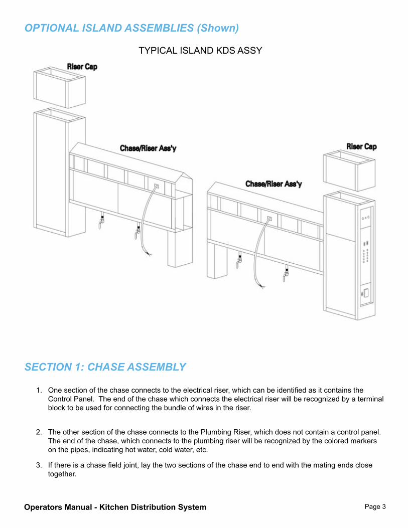
OPTIONAL ISLAND ASSEMBLIES (Shown)
TYPICAL ISLAND KDS ASSY
SECTION 1: ChASE ASSEMBLy
1. One section of the chase connects to the electrical riser, which can be identified as it contains the Control Panel. The end of the chase which connects the electrical riser will be recognized by a terminal block to be used for connecting the bundle of wires in the riser.
2. The other section of the chase connects to the Plumbing Riser, which does not contain a control panel. The end of the chase, which connects to the plumbing riser will be recognized by the colored markers on the pipes, indicating hot water, cold water, etc.
3. If there is a chase field joint, lay the two sections of the chase end to end with the mating ends close together.
Operators Manual - Kitchen Distribution System Page 4
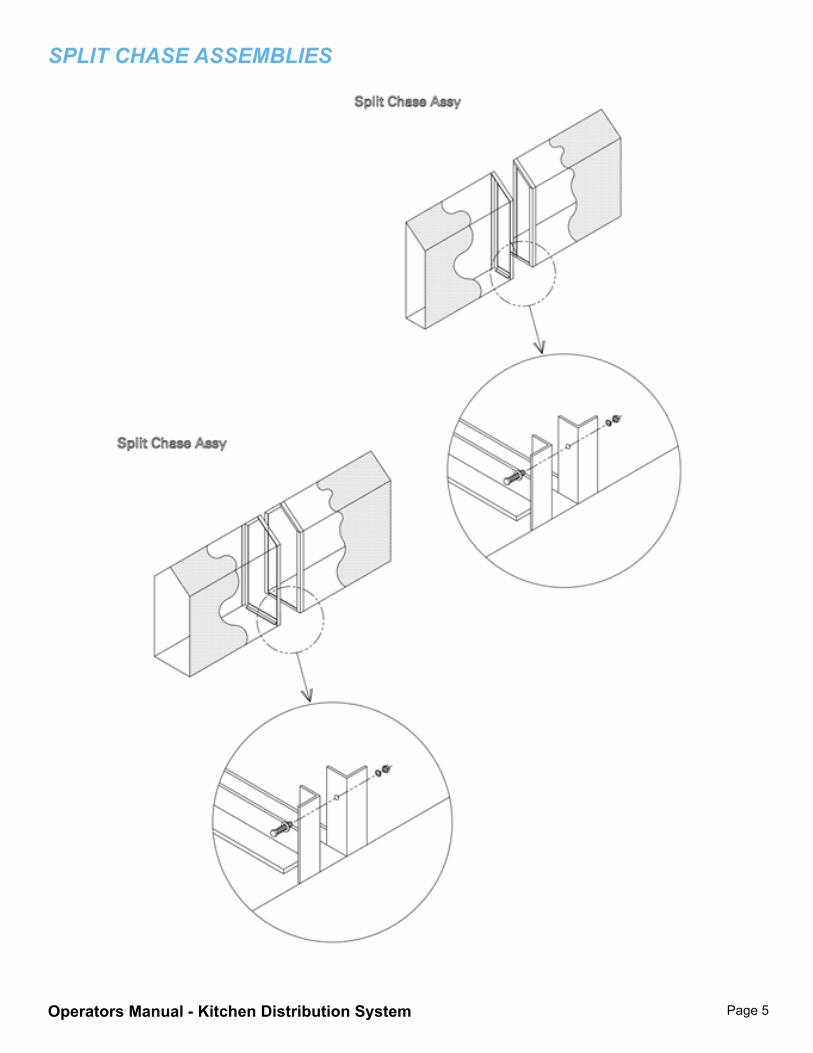
(Figure on Page 5) Note that:
3.1 Each section contains access covers that may be removed, giving access to the interior, even after the sections are bolted together. These covers should be removed.
3.2 Plumbing pipes are connected to the frame of the chase with brackets that may be loosened to permit movement of the pipe when the union is screwed to the mating thread. Loosen the brackets so that the pipes may move freely. (Use caution and only loosen the brackets when necessary. The pipes may be heavy. Be sure fingers, hands or other appendages are not below the pipes while they are being loosened.)
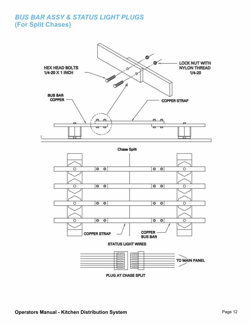
3.3 A longer KDS unit’s chase is shipped in sections. In each section of a “bus bar” system, flat rectangular copper bus bars are arranged for the transmission of electrical current. Note that, when the sections of the chaser are laid together, the copper bus bars do not meet. The assembly kit contains pieces of bus bar for joining the two sections, along with the necessary hardware (bolts, nuts, washers and lock washers). (Figure on Page 12)
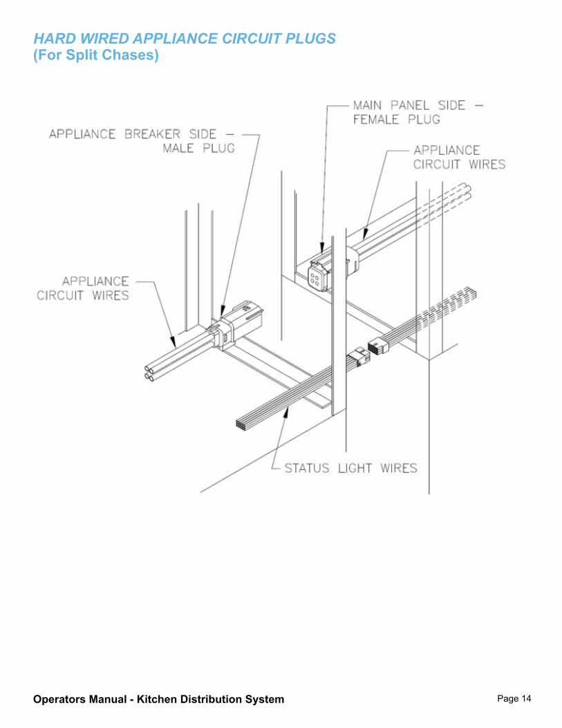
3.4 Alternately a system may be “hardwired” from the control panel to the appliance outlet locations. In this case plug connectors for the appliance circuits will have to be joined where the chase sections assemble together. Mating appliance circuit plugs will be labeled to ensure correct connections.
3.5 Both the “bus bar” type KDS and the “hardwired” type KDS will have a plug connection for the appliance status lights at each chase field joint. These plug connections must be joined.
3.6 The frame of each section has a flange at the end where the two sections are to be joined mechanically. Note that there are mating holes permitting the two sections to be bolted together. Hardware has been provided. For the mechanical assembly of the two sections of the chase, refer to (Figure on Page 5)
4. Mechanically assemble the two sections by installing the intermediate pedestals bolting the flanges. The pipes may also be loosely connected at this time. Carefully tighten the bolts connecting the flanges, using the bolts, nuts, washers and lock washers provided. The pipe unions may also be gradually tightened during this step. For the plumbing assembly, refer to Figures on Page 8 & 9.
5. After the flanges have been completely tightened, complete the plumbing assembly by tightening the unions.
Operators Manual - Kitchen Distribution System Page 5
SPLIT ChASE ASSEMBLIES
Operators Manual - Kitchen Distribution System Page 6
SECTION 1: ChASE ASSEMBLy (CONTINUED)
NOTE: PLUMBING ASSEMBLY SHOULD BE COMPLETED BY A RESPONSIBLE CONTRACTOR AS THESE PIPES WILL CARRY HOT WATER AND, IN SOME INSTANCES, STEAM AND GAS; THE HALTON COMPANY IS NOT RESPONSIBLE FOR IMPROPER OPERATION OR INJURY DUE TO ASSEMBLY BY PERSONS WHO ARE NOT QUALIFIED AND BONDED.
1. For the electrical assembly, refer to Figures on pages 12 & 14. Connect the bus bars (if it is a bus bar system) with the sections provided, using the bolts, nuts, washers and lock washers provided. Be certain that the mating surfaces are free of all burrs that might prevent smooth contact and that the mating surfaces are clean. Panel box system requires connection of wires in the chase. NOTE: ELECTRICAL ASSEMBLY SHOULD BE DONE BY THE ELECTRICAL CONTRACTOR AS THESE BUS BARS OR PANEL BOX CARRY HIGH CURRENT AT HAZARDOUS VOLTAGE. HALTON COMPANY IS NOT RESPONSIBLE FOR IMPROPER OPERATION OR INJURY DUE TO ASSEMBLY BY PERSONS WHO ARE NOT QUALIFIED AND BONDED.
2. When the mechanical, plumbing and electrical connections have been completed the intermediate pedestals must be mechanically bolted to the chase.
SECTION 2: ASSEMBLINg ThE RISERS AND ThE hORIzONTAL ChASE
It is recommended that the risers be placed vertically in position before the horizontal chase is mechanically bolted to the risers. This is to avoid the stress and strain that might be applied to the assembly when it is moved into position. The entire assembly should be externally braced and the positioning checked before either riser is anchored to the floor. The risers have been designed to project a distance of two inches above the ceiling of the kitchen. It is strongly recommended that these risers be anchored to the structural members of the ceiling or the roof of the building to prevent any movement after installation. NOTE: ANY MOVEMENT AFTER ASSEMBLY WILL THREATEN THE INTEGRITY OF THE ELECTRICAL CONNECTIONS AND PLUMBING JOINTS AND COULD BE A SOURCE OF IMPROPER OPERATION OR HAZARD.
1. The vertical risers should be erected in position and braced externally before the horizontal chase is attached. Neither riser should be anchored to the floor at this time.
Operators Manual - Kitchen Distribution System Page 7
2. The horizontal chase is placed in position and firmly bolted to the risers with the hardware provided using bolts, nuts, washers and lock washers.
3. When the mechanical assembly of the chase and the risers is complete, the risers should be anchored firmly to the floor and to the structural support above the ceiling.
PLUMBINg INSTALLATION (By PLUMBINg CONTRACTORS)
1. Other than supply lines, all plumbing interior to the KDS assembly is factory supplied.
2. Water supplies exceeding 40 PSI pressure require a pressure reducer to be supplied by the plumbing contractor.
3. All pipe sizes must be in accordance with the design sizes specified on the drawings specific to the particular installation.
4. The plumbing contractor will supply cold water, hot water, gas steam and condensate return lines through the plumbing riser according to the specifications in the drawings provided for the particular installation.
5. Internal plumbing has been appropriately identified and leak tested by the factory. Plumbing connections between the drops, or output ports of the KDS, and the appropriate appliance will be supplied by the plumbing contractor, unless the contract specifies the factory will provide such plumbing.
6. Following the connection of all plumbing supplies, a final check of the joints connecting the two sections of the chaser should be made, if applicable.
7. Brackets holding the pipes in position of the KDS frame should be tightened after the KDS frame is anchored firmly to the floor and structural ceiling, and after all other mechanical connections between the risers, chase and pedestal have been completed.
Operators Manual - Kitchen Distribution System Page 8
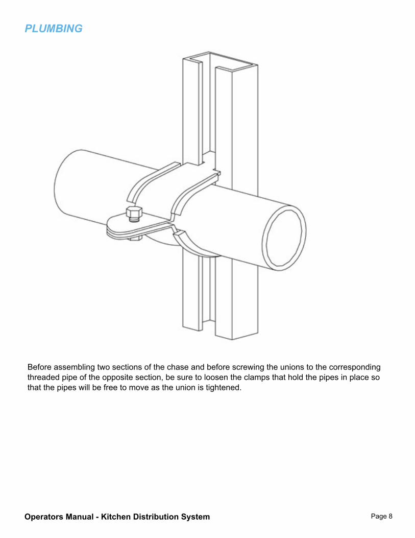
PLUMBINg
Before assembling two sections of the chase and before screwing the unions to the corresponding threaded pipe of the opposite section, be sure to loosen the clamps that hold the pipes in place so that the pipes will be free to move as the union is tightened.
Operators Manual - Kitchen Distribution System Page 9
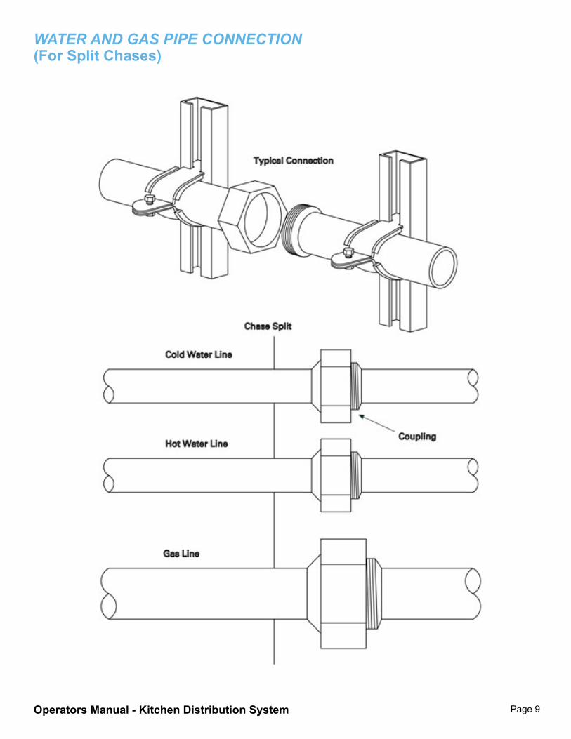
WATER AND gAS PIPE CONNECTION (For Split Chases)
Operators Manual - Kitchen Distribution System Page 10
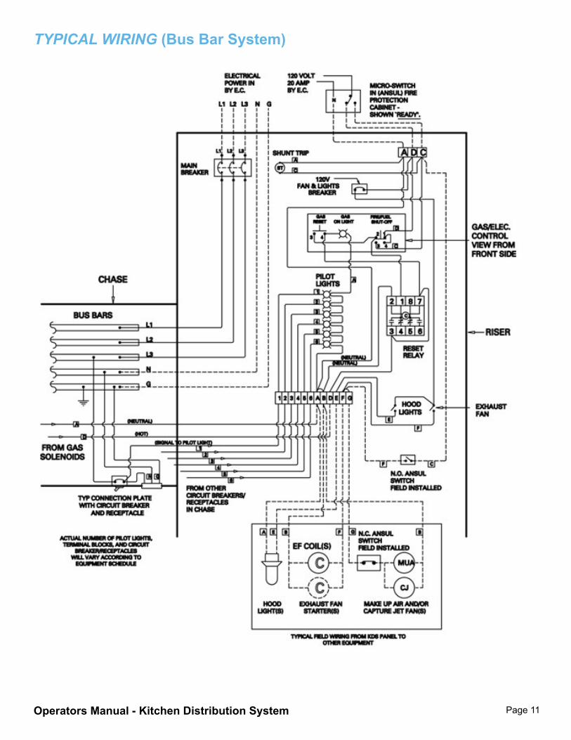
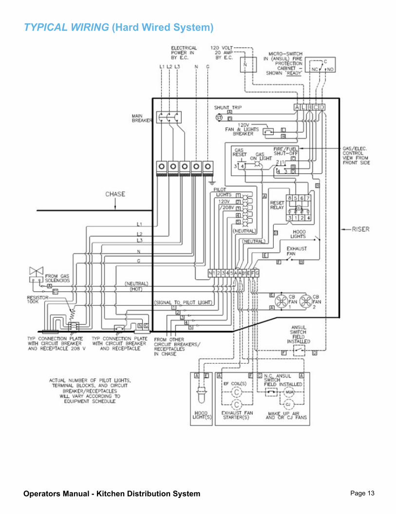
ELECTRICAL INSTALLATION (By ELECTRICAL CONTRACTOR)
1. All electrical wiring must be according to the National Electrical Code and must be acceptable the authorities having jurisdiction.
2. The factory has provided a wire harness from the control panel and this must be connected to the terminal block and bus bars if a bus bar system. Both the terminal block and the wire harness have been labeled for correct connection.
3. The electrical contractor will provide power to the main terminal block in the riser, according to the specifications on the electrical drawing appropriate to the particular installation.
4. The electrical contractor will provide the connections from the switch in the fire suppression system to the appropriate terminals in the KDS electrical riser.
5. As far as internal connections are concerned, the factory has tested all circuitry for continuity and function prior to shipment. Note, however, that, when all electrical connections have been made; a final check should be made of the connections between the bus bars and receptacles.
Operators Manual - Kitchen Distribution System Page 11
TyPICAL WIRINg (Bus Bar System)
Operators Manual - Kitchen Distribution System Page 12
BUS BAR ASSy & STATUS LIghT PLUgS (For Split Chases)
Operators Manual - Kitchen Distribution System Page 13
TyPICAL WIRINg (Hard Wired System)
Operators Manual - Kitchen Distribution System Page 14
hARD WIRED APPLIANCE CIRCUIT PLUgS (For Split Chases)
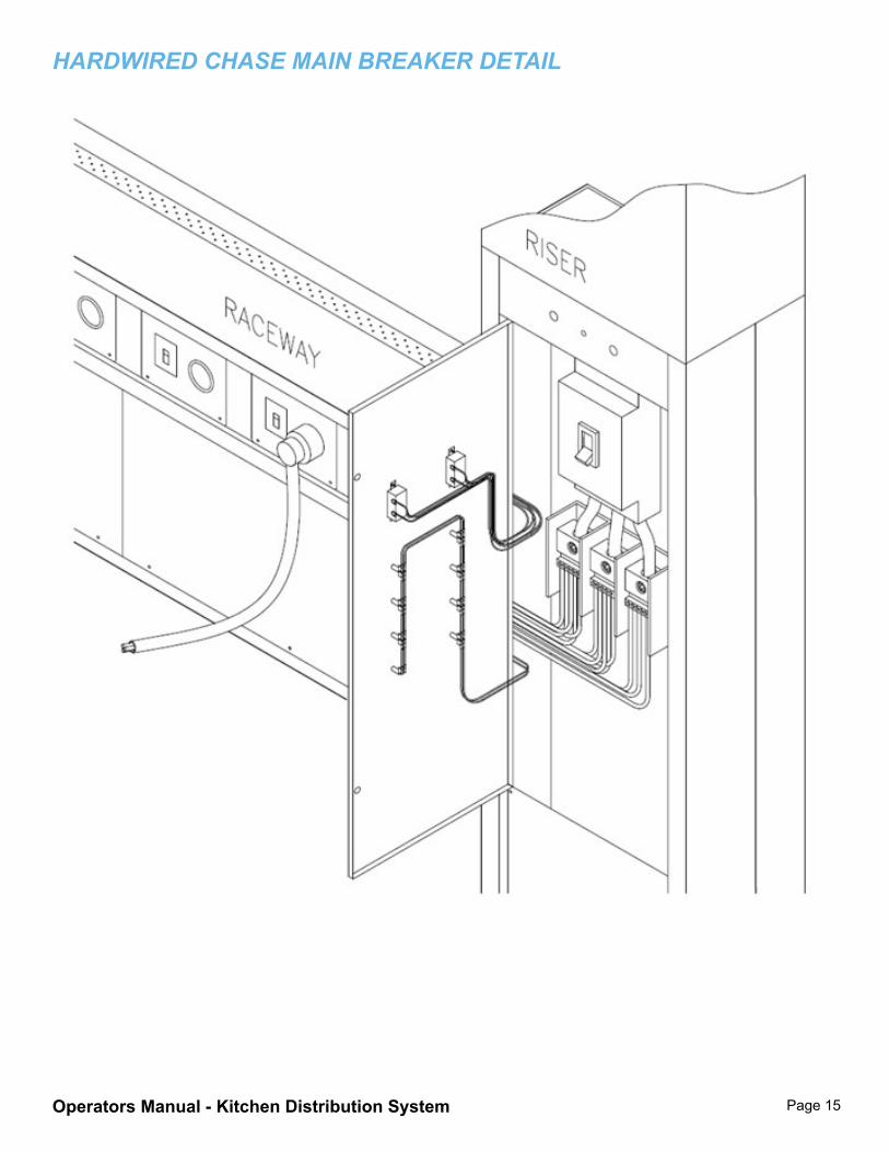
Operators Manual - Kitchen Distribution System Page 15
hARDWIRED ChASE MAIN BREAKER DETAIL
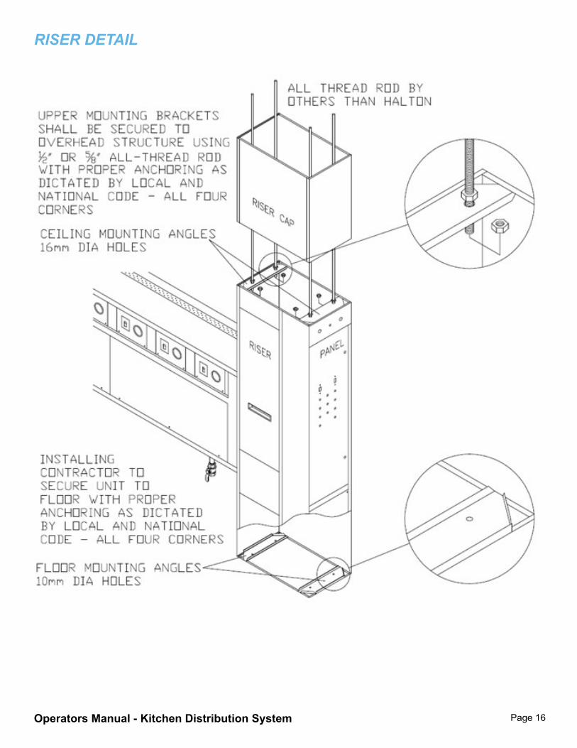
Operators Manual - Kitchen Distribution System Page 16
RISER DETAIL
Operators Manual - Kitchen Distribution System Page 17
FINAL ChECK At the completion of the installation, engaging the main circuit breaker should illuminate appropriate lights on the control panel. This is an indication that the circuit breakers for the individual drops, or outputs are in the closed position. If one or more lights are not on, check the corresponding circuit breaker in the chase to ensure that it is engaged in the ON position.
NOTE: ALL ACCESS AND INSPECTIONS PLATES MUST BE BOLTED FIRMLY IN POSITION BEFORE ACTIVATING THE ELECTRICAL, PLUMBING AND HVAC SUPPLIES. THE HALTON KDS CONTAINS HAZARDOUS VOLTAGES AND TEMPERATURES. ACCESS AND INSPECTION COVERS PROVIDE PROTECTION AGAINST THESE HAZARDS.
MAINTENANCE Clean the Kitchen Distribution System with mild soap and water when necessary.
CAUTION: Do not introduce water or any object into the appliance outlet receptacle. Never use harsh or abrasive cleaners on Stainless Steel or Painted surfaces.
MODIFICATION To change or add additional Circuit Plates to the KDS Utility Distribution System
1. Shut off all electrical feed circuits to the KDS Utility Distribution System. Lock out and Tag out all sources of electrical energy to the KDS to be modified.
2. Remove blank Circuit Plate from the desired location along the electrical chase of the KDS. This will be accomplished by the removal of four screws for each plate. If existing Circuit Plate to be removed has outlet and circuit breaker, the feed wires will have to be removed from the wire anchor lugs on the appropriate bus bars. See step 4 below regarding removing the access plates that cover the bus bar area.
3. Bring the new Circuit Plate to the location desired for installation. Four foot lengths of wire have been attached at the factory, consisting of a hot (black) wire, neutral (white) wire and ground (green) wire for a 120 volt circuit. Wiring quantities and sizes differ for different voltage circuits.
4. Remove the access plates that cover the bus bar electrical distribution system in the location of the new Circuit Plate.
Drill holes in the desired bus bars corresponding to the circuit that the new plate will be powered from. The size hole to drill corresponds to the bolt used to attach the wire anchor lug to the bus bar (see step 7). Circuits up to 99 amps use a ¼-20 bolt in the wire anchor lug, circuits 100 amps and up use a 3/8-16 bolt. (For example in a typical 120 volt single phase bus bar layout: L1 is identified
Operators Manual - Kitchen Distribution System Page 18
by black tape on the source wire connected to the bus bar closest to the electrical panel. L2 is identified by red tape, L3 is identified by blue tape, the Neutral bus bar is identified by white tape and the Ground bus bar is identified by green tape.) Three phase voltages are distributed with additional bus bars in sets of three. Multiple voltages, including multiple set of three phase voltages, may be present in the bus bar distribution system. See job specific wiring details included with the KDS system for voltage and bus bar layout information.
6. Drill holes each in the Neutral bus bar and the Ground bus bar.
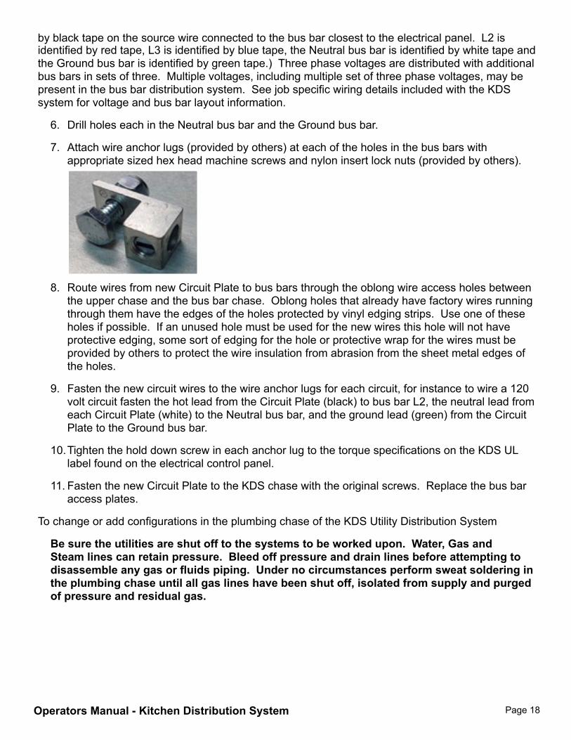
7. Attach wire anchor lugs (provided by others) at each of the holes in the bus bars with appropriate sized hex head machine screws and nylon insert lock nuts (provided by others).
8. Route wires from new Circuit Plate to bus bars through the oblong wire access holes between the upper chase and the bus bar chase. Oblong holes that already have factory wires running through them have the edges of the holes protected by vinyl edging strips. Use one of these holes if possible. If an unused hole must be used for the new wires this hole will not have protective edging, some sort of edging for the hole or protective wrap for the wires must be provided by others to protect the wire insulation from abrasion from the sheet metal edges of the holes.
9. Fasten the new circuit wires to the wire anchor lugs for each circuit, for instance to wire a 120 volt circuit fasten the hot lead from the Circuit Plate (black) to bus bar L2, the neutral lead from each Circuit Plate (white) to the Neutral bus bar, and the ground lead (green) from the Circuit Plate to the Ground bus bar.
10. Tighten the hold down screw in each anchor lug to the torque specifications on the KDS UL label found on the electrical control panel.
11. Fasten the new Circuit Plate to the KDS chase with the original screws. Replace the bus bar access plates.
To change or add configurations in the plumbing chase of the KDS Utility Distribution System
Be sure the utilities are shut off to the systems to be worked upon. Water, Gas and Steam lines can retain pressure. Bleed off pressure and drain lines before attempting to disassemble any gas or fluids piping. Under no circumstances perform sweat soldering in the plumbing chase until all gas lines have been shut off, isolated from supply and purged of pressure and residual gas.
Operators Manual - Kitchen Distribution System Page 19
Standard plumbing practices are used for modification of the Halton KDS Water, Gas, Steam, Condensate return or other hard piped utility lines. The hot and cold water lines are copper pipe, assembled by sweat solder techniques. They are foam wrap insulated and pressure tested at the factory at 75 psi for two hours. Remove any insulation from the area to be modified and take precautions that no flammable materials are in danger of catching fire during sweat solder operations. After modifications, assembly and pressure testing is complete re-insulate pipes with comparable insulation wrap. All other utility lines, gas, steam, condensate return, etc., are black iron and assembled with standard elbows, tees, couplings, etc. They are felt wrap insulated and pressure tested at the factory to 50 psi for two hours. After modifications, assembly and pressure testing are complete re-insulate pipes with comparable insulation wrap before placing into service.

WARRANTY ACTIVATION FORM
This form must be completed and returned to Halton in order for your warranty to be valid.
Job & Location Information:
Job Name:
Street Name:
City: State: Zip Code: Equipment Start-Up Date: Product Serial Numbers:
Contact Information:
Contact Name:
Title: Chef, Kitchen Mgr/Facility Mgr/Property Mgr/etc.
Facility Management Company Name (if applicable):
Email:
Phone Number: Cell Number:
Fax completed form to:Halton CompanyAttention: Service DepartmentFax: (270) 237-5700
Halton Indoor Climate SystemsAttention: Service DepartmentFax: (905) 624-5547
OM
-015
/112
016/
rev1
/EN
Operators Manual - Kitchen Distribution System

HALTON LIMITED WARRANTYHalton (“Manufacturer”). Warrants only to its direct purchasers and to no others, that all products manufactured by the Manufacturer shall be free from defect in materials and workmanship for a period of twelve (12) months from the date of the original installation and start-up or eighteen (18) months from date of shipment, whichever occurs first. All products sold but not manufactured by Manufacturer will be warranted for a period of twelve (12) months from date of shipment. (Halton’s Warranty Card must be completely filled out and returned to Halton within 3 weeks after the equipment start-up date for your warranty to be valid *IMPORTANT NOTE: “IF” this form is returned within the specified time frame, Halton will extend your standard warranty by 120 days.)
For products manufactured by the Manufacturer we agree to pay any reasonable labor costs necessary to repair or replace, at Manufacturers option, defective parts or materials for a period of twelve (12) months from date of original installation and start-up or eighteen (18) months from date of shipment, whichever occurs first. All labor costs subject hereto shall be performed during standard work hours at straight-time rates.
For products sold but not manufactured by the Manufacturer we agree to pay any reasonable labor costs necessary to repair or replace, at Manufacturers option, defective parts or materials for a period of (90) days from date of original installation and start-up or (12) months from date of shipment, whichever occurs first. All labor costs subject hereto shall be performed during standard work hours at straight time rates.
All warranty claims that include labor requires pre-approval by Halton. Halton, at its discretion, will authorize field warranty work through its own service network or certified third party. No claims for labor charges will be approved for payment if work commences without prior authorization by Halton.
Purchaser shall pay incurred premium labor charge, including overtime, weekends and holidays. Travel time, service charges, miscellaneous tools, material charges, and labor charges resulting from inaccessibility of equipment will not be paid by Manufacturer.
This LIMITED WARRANTY SHALL APPLY ONLY to products that have been installed and maintained in accordance with the installation and Care Instruction Manuals. Purchaser shall be solely responsible for adhering to the instructions and procedures set forth in the said instruction manuals.
This LIMITED WARRANTY SHALL NOT BE APPLICABLE to any damage or defect resulting from fire, flood, freezing or any Act of God, abuse, misuse, accident, neglect or failure to adhere to all instructions set forth in the installation and Care Instruction Manuals. Furthermore, this limited warranty shall not apply to any product that has been altered, unless such alteration has been approved in writing by a duly authorized representative of the manufacturer. In no event shall the manufacturer be liable for any loss, expense, personal injury or consequential damage, of any kind or character, as may result from a defect in material, and/or workmanship, however caused.
EXCEPT AS IS EXPRESSLY SET FORTH IN THIS LIMITED WARRANTY, MANUFACTURER MAKES NO WARRANTY OF MARKETABILITY FOR FITNESS OR ANY PARTICULAR PURPOSE. NEITHER DOES MANUFACTURER MAKE ANY WARRANTY, EXPRESSED OR IMPLIED, WITH RESPECT TO PRODUCTS SOLD BY MANUFACTURER OR AS TO THE USE THEREOF.
Continuous product improvement is a Halton policy, therefore specifications and design are subject to change without notice.
Halton Company101 Industrial Drive, Scottsville, KY 42164, USAPhone 270 237 5600 | Fax 270 237 5700Website: www.halton.com
Halton Indoor Climate Systems, Ltd.1021 Brevik Place, Mississauga, ON L4W 3R7, CanadaPhone 905 624 0301 | Fax 905 624 0301
OM
-015
/112
016/
rev1
/EN