OPERATOR MANUAL C Series Small Steam Sterilizers … C Operator … · · 2017-01-30AMSCO® C...
154
OPERATOR MANUAL AMSCO ® C Series Small Steam Sterilizers 16 x 16" (406 x 406mm) 20 x 20" (508 x 508 mm) • Prevacuum • Steam Flush Pressure Pulse (05/07/12) P129394-176
Transcript of OPERATOR MANUAL C Series Small Steam Sterilizers … C Operator … · · 2017-01-30AMSCO® C...

OPERATOR MANUAL
AMSCO® C Series Small Steam Sterilizers16 x 16" (406 x 406mm)20 x 20" (508 x 508 mm)
• Prevacuum • Steam Flush Pressure Pulse
(05/07/12) P129394-176
A WORD FROM STERIS CORPORATION
This manual contains important information on proper use of thissterilizer. All operators and department heads must carefullyreview and become familiar with the warnings, cautions andinstructions contained in this manual. These instructions areimportant to the health and safety of personnel operating thesterilizer and should be retained in a conveniently accessible areafor quick reference.
This sterilizer is specifically designed to process goods using onlythe cycles as specified in this manual. If there is any doubt about aspecific material or product, contact the manufacturer of the productfor the recommended sterilization technique.
STERIS Corporation carries a complete line of accessories for thisunit to simplify, organize and assure the conditions for sterilizationhave been achieved. Instrument trays, pouches and biological/chemical monitoring systems are all available to fulfill your facility’sprocessing needs. STERIS® will gladly review these with you.
Service Information A thorough preventive maintenance program is essential to safe andproper sterilizer operation. You are encouraged to contact STERISconcerning our Preventive Maintenance Agreement. Under terms ofthis agreement, preventive maintenance, adjustments andreplacement of worn parts are done on a scheduled basis to assureequipment performance at peak capability and help avoid untimelyor costly interruptions. STERIS maintains a worldwide staff of well-equipped, factory-trained technicians to provide this service, as wellas expert repair services. Contact your STERIS representative fordetails.
Indications for Use The AMSCO® C Series Small Steam Sterilizer is designed forsterilization of heat- and moisture-stable materials used in healthcarefacilities and is available in two models:
• Prevacuum – designed for sterilization of heat- and moisture-stable materials. The Prevacuum sterilizer is equipped withPrevacuum, Gravity, Liquid, Leak Test and Dart (Bowie-Dick)cycles.
• Steam Flush Pressure Pulse (SFPP) – designed for sterilizationof heat and moisture-stable materials. The SFPP sterilizer isequipped with SFPP, Prevacuum, Gravity, Liquid, Leak Test andDart (Bowie-Dick) cycles.
Important: The liquid cycle is for non-patient contact use only.
iIntroduction Operator Manual P129394-176
© 2012, STERIS Corporation. All rights reserved. Printed in U.S.A.

(Continued on following page.)
Factory-Set Cycles and Cycle Values1
The AMSCO C Series 16C and 20C Prevacuum Small Steam Sterilizer 16 x 16" (406 x 406 mm) and 20 x 20" (508x 508 mm) is equipped with the following factory programmed sterilization cycles and cycle values (Table 1).
NOTE: Default cycles for SFPP sterilizer shown in Table 1B on following page.
1. Supervisor must enable access to optional cycles, such as the Liquids Cycle.
Table 1. Factory Default Cycles, Prevacuum Configuration
Cycles: Sterilize Temp.
Sterilize Time
Dry Time Recommended Load* Validation
Standard
1. Immediate UsePrevac Cycle
270°F (132°C)
4 Minutes 1 Minute Unwrapped instrument tray containing a single instrument; or multiple unwrapped instrument trays, porous and non-porous loads. Maximum weight per tray: 25 lb (11.3 kg)
ST-8:2008
2. Prevac Cycle 270°F (132°C)
4 Minutes 30 Minutes Double-wrapped instrument trays containing multiple instruments, porous and non-porous loads. Maximum weight per tray: 25 lb (11.3 kg)
ST-8:2008
3. Prevac Cycle 275°F (135°C)
3 Minutes 30 Minutes Double-wrapped instrument trays containing multiple instruments, porous and non-porous loads. Maximum weight per tray: 25 lb (11.3 kg)
ST-8:2008
4. Prevac Cycle 270°F (132°C)
4 Minutes 20 Minutes**
Fabric Packs. ST-8:2008
5. Immediate UseGravity Cycle
270°F (132°C)
10 Minutes 1 Minute Unwrapped instrument tray containing a single instrument; or multiple unwrapped instrument trays, non-porous load. Maximum weight per tray: 25 lb (11.3 kg).
ST-8:2008
6. Immediate Use Gravity Cycle
270°F (132°C)
3 Minutes 1 Minute ST-8:2008
* See Table 4 for recommended quantities.** Dry time can be reduced to 5 minutes for a single fabric pack.
iiP129394-176 Operator Manual Introduction
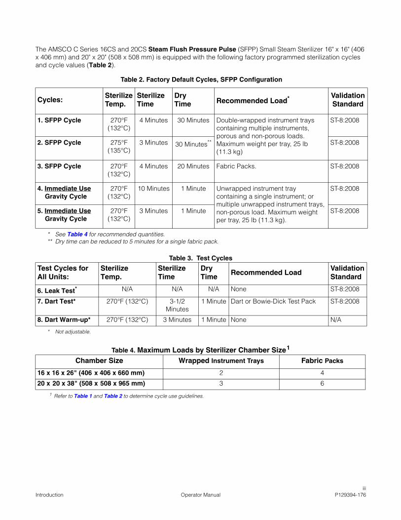
The AMSCO C Series 16CS and 20CS Steam Flush Pressure Pulse (SFPP) Small Steam Sterilizer 16" x 16" (406 x 406 mm) and 20" x 20" (508 x 508 mm) is equipped with the following factory programmed sterilization cycles and cycle values (Table 2).
Table 3. Test Cycles
Table 4. Maximum Loads by Sterilizer Chamber Size1
Table 2. Factory Default Cycles, SFPP Configuration
Cycles: Sterilize Temp.
Sterilize Time
Dry Time Recommended Load*
* See Table 4 for recommended quantities.
Validation Standard
1. SFPP Cycle 270°F (132°C)
4 Minutes 30 Minutes Double-wrapped instrument trays containing multiple instruments, porous and non-porous loads. Maximum weight per tray, 25 lb (11.3 kg)
ST-8:2008
2. SFPP Cycle 275°F (135°C)
3 Minutes 30 Minutes**
** Dry time can be reduced to 5 minutes for a single fabric pack.
ST-8:2008
3. SFPP Cycle 270°F (132°C)
4 Minutes 20 Minutes Fabric Packs. ST-8:2008
4. Immediate Use Gravity Cycle
270°F (132°C)
10 Minutes 1 Minute Unwrapped instrument tray containing a single instrument; or multiple unwrapped instrument trays, non-porous load. Maximum weight per tray, 25 lb (11.3 kg).
ST-8:2008
5. Immediate Use Gravity Cycle
270°F (132°C)
3 Minutes 1 Minute ST-8:2008
Test Cycles for All Units:
Sterilize Temp.
Sterilize Time
Dry Time Recommended Load
Validation Standard
6. Leak Test*
* Not adjustable.
N/A N/A N/A None ST-8:2008
7. Dart Test* 270°F (132°C) 3-1/2 Minutes
1 Minute Dart or Bowie-Dick Test Pack ST-8:2008
8. Dart Warm-up* 270°F (132°C) 3 Minutes 1 Minute None N/A
Chamber Size Wrapped Instrument Trays Fabric Packs
16 x 16 x 26" (406 x 406 x 660 mm) 2 4
20 x 20 x 38" (508 x 508 x 965 mm) 3 6
1 Refer to Table 1 and Table 2 to determine cycle use guidelines.
iiiIntroduction Operator Manual P129394-176

Table 5. Liquid Cycle Processing Guidelines
Advisory This sterilizer is specifically designed to only process goods using the cyclesas specified in this manual. If there is any doubt about a specific material orproduct, contact the manufacturer of that product for the recommendedsterilization technique.
A summary of the safety precautions to be observed when operating andservicing this equipment can be found in SECTION 1 of this manual. Do notoperate or service the equipment until you have become familiar with thisinformation.
Any alteration of the sterilizer not authorized or performed by STERIS will voidthe warranty. Alteration of the equipment which could adversely affect itsoperation and sterilization efficacy may violate national, state and local lawsor regulations.
Manufactured by:
STERIS Corporation.6515 Hopkins RoadMentor, OH 44060 • USA
Sterilizer Size
Number of Containers for Liquid Cycle*
Full Load
Volume of Liquid in One Container
Minimum Recommended
Sterilize Time at 250°F (121°C) in Minutes
16 x 16 x 26" (406 x 406 x 660 mm) 15
1000 mL 4520 x 20 x 38” (508 x 508 x 965 mm)
with Loading Car32
20x 20 x 38” (508 x 508 x 965 mm) with Rack and Shelves
28
* The liquid cycle is for non-patient contact use only.
Table 6. Sterilizer Configurations
AMSCO C Small Steam Sterilizers are offered in the following configurations:
16" Configurations
16 x 16 x 26" (406 x 406 x 660 mm) Single Door, Prevacuum
16 x 16 x 26" (406 x 406 x 660 mm) Single Door, SFPP
16 x 16 x 26" (406 x 406 x 660 mm) Double Door, Prevacuum
16 x 16 x 26" (406 x 406 x 660 mm) Double Door, SFPP
20" Configurations
20 x 20 x 38" (508 x 508 x 965 mm) Single Door, Prevacuum
20 x 20 x 38" (508 x 508 x 965 mm) Single Door, SFPP
20 x 20 x 38" (508 x 508 x 965 mm) Double Door, Prevacuum
20 x 20 x 38" (508 x 508 x 965 mm) Double Door, SFPP
Sales and Service:
STERIS Corporation5960 Heisley RoadMentor, Ohio 44060440-354-2600 • 800-444-9009
www.steris.com
ivP129394-176 Operator Manual Introduction

TABLE OF CONTENTS
Section Number Description Page
1 Safety Precautions ........................................................................................................................ 1-1
2 Symbol Definitions ........................................................................................................................ 2-1
3 Installation Verification ................................................................................................................. 3-13.1 Installation Checklist ............................................................................................................................ 3-1
3.1.1 Service Clearance ................................................................................................................... 3-1
3.1.2 Plumbing Services................................................................................................................... 3-1
3.1.3 Electrical Service..................................................................................................................... 3-2
3.1.4 Sterilizer Final Check .............................................................................................................. 3-2
3.1.5 Cycle Operation....................................................................................................................... 3-2
3.2 Technical Specifications ...................................................................................................................... 3-3
3.2.1 Overall Size ............................................................................................................................. 3-3
3.2.2 Weight (Fully Loaded) ............................................................................................................. 3-3
3.2.3 Utility Requirements ................................................................................................................ 3-3
3.2.4 Environmental Conditions ....................................................................................................... 3-3
4 Techniques of Sterilization........................................................................................................... 4-14.1 General ................................................................................................................................................ 4-1
4.2 Immediate Use..................................................................................................................................... 4-4
4.3 Control Measures for Verifying Sterilization Process........................................................................... 4-4
4.3.1 Biological Monitors .................................................................................................................. 4-5
4.3.2 Testing for Prevacuum Efficiency............................................................................................ 4-5
4.4 Dart (Bowie-Dick) Test......................................................................................................................... 4-5
4.5 Vacuum Leak Test ............................................................................................................................... 4-6
4.6 Recommendations for the Sterilization Process .................................................................................. 4-6
4.7 Techniques of Sterilization for Liquid Cycle ......................................................................................... 4-7
4.8 Recommendations for Sterilizing Liquids............................................................................................. 4-8
4.9 Sterilization of Implantable Devices ..................................................................................................... 4-8
5 Component Identification ............................................................................................................. 5-15.1 General ................................................................................................................................................ 5-2
5.2 Main Sterilizer and Cycle Controls....................................................................................................... 5-2
5.3 Control Displays................................................................................................................................... 5-4
5.4 Alarm Displays ..................................................................................................................................... 5-5
5.5 Operating End Control Panel ............................................................................................................... 5-6
5.6 Cycle Selection Touch-screen Pads .................................................................................................... 5-8
5.6.1 Values Touch-Screen Pads..................................................................................................... 5-9
5.6.2 Abort Touch-Screen Pad....................................................................................................... 5-10
5.7 Printer ................................................................................................................................................ 5-11
5.8 Printouts............................................................................................................................................. 5-12
vTable of Contents Operator Manual P129394-176
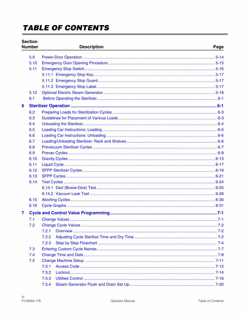
TABLE OF CONTENTS
Section Number Description Page
5.9 Power-Door Operation ....................................................................................................................... 5-14
5.10 Emergency Door Opening Procedure................................................................................................ 5-15
5.11 Emergency Stop Switch..................................................................................................................... 5-16
5.11.1 Emergency Stop Key............................................................................................................. 5-17
5.11.2 Emergency Stop Guard......................................................................................................... 5-17
5.11.3 Emergency Stop Label .......................................................................................................... 5-17
5.12 Optional Electric Steam Generator .................................................................................................... 5-18
6.1 Before Operating the Sterilizer............................................................................................................ 6-1
6 Sterilizer Operation ....................................................................................................................... 6-16.2 Preparing Loads for Sterilization Cycles .............................................................................................. 6-3
6.3 Guidelines for Placement of Various Loads......................................................................................... 6-3
6.4 Unloading the Sterilizer........................................................................................................................ 6-4
6.5 Loading Car Instructions: Loading ....................................................................................................... 6-5
6.6 Loading Car Instructions: Unloading.................................................................................................... 6-6
6.7 Loading/Unloading Sterilizer: Rack and Shelves ................................................................................. 6-6
6.8 Prevacuum Sterilizer Cycles ................................................................................................................ 6-7
6.9 Prevac Cycles ...................................................................................................................................... 6-9
6.10 Gravity Cycles.................................................................................................................................... 6-13
6.11 Liquid Cycle ....................................................................................................................................... 6-17
6.12 SFPP Sterilizer Cycles....................................................................................................................... 6-19
6.13 SFPP Cycles...................................................................................................................................... 6-21
6.14 Test Cycles ........................................................................................................................................ 6-24
6.14.1 Dart (Bowie-Dick) Test .......................................................................................................... 6-25
6.14.2 Vacuum Leak Test ................................................................................................................ 6-28
6.15 Aborting Cycles.................................................................................................................................. 6-30
6.16 Cycle Graphs ..................................................................................................................................... 6-31
7 Cycle and Control Value Programming....................................................................................... 7-17.1 Change Values .................................................................................................................................... 7-1
7.2 Change Cycle Values .......................................................................................................................... 7-2
7.2.1 Overview ................................................................................................................................. 7-2
7.2.2 Adjusting Cycle Sterilize Time and Dry Time .......................................................................... 7-2
7.2.3 Step by Step Flowchart ........................................................................................................... 7-4
7.3 Entering Custom Cycle Names............................................................................................................ 7-7
7.4 Change Time and Date........................................................................................................................ 7-8
7.5 Change Machine Setup ..................................................................................................................... 7-11
7.5.1 Access Code ......................................................................................................................... 7-12
7.5.2 Lockout .................................................................................................................................. 7-14
7.5.3 Utilities Control ...................................................................................................................... 7-16
7.5.4 Steam Generator Flush and Drain Set Up............................................................................. 7-20
viP129394-176 Operator Manual Table of Contents
TABLE OF CONTENTS
Section Number Description Page
7.5.5 Steam Generator Flush Cycle ............................................................................................... 7-21
7.5.6 Language .............................................................................................................................. 7-22
7.5.7 Machine Number ................................................................................................................... 7-23
7.5.8 Time Format .......................................................................................................................... 7-23
7.5.9 Print Format........................................................................................................................... 7-24
7.5.10 Audible Signals...................................................................................................................... 7-27
7.5.11 Units ...................................................................................................................................... 7-28
7.5.12 Date Format .......................................................................................................................... 7-28
7.5.13 Duplicate Print ....................................................................................................................... 7-29
7.6 Leaving Change Values..................................................................................................................... 7-30
8 Routine Maintenance..................................................................................................................... 8-18.1 Preventive Maintenance Schedule ...................................................................................................... 8-1
8.2 Daily Maintenance Procedures ............................................................................................................ 8-3
8.2.1 Check Printer Paper Supply .................................................................................................... 8-3
8.2.2 Clean Chamber Drain Strainer ................................................................................................ 8-3
8.3 Weekly Maintenance Procedure: Flush Chamber Drain...................................................................... 8-4
8.4 Chamber Cleaning ............................................................................................................................... 8-5
8.5 Printer Maintenance............................................................................................................................. 8-7
8.5.1 Change Printer Paper Roll ...................................................................................................... 8-7
8.5.2 Change Printer Ink Cartridge................................................................................................. 8-12
9 Troubleshooting ............................................................................................................................ 9-19.1 General ................................................................................................................................................ 9-1
9.1.1 Typical Alarm Screen .............................................................................................................. 9-1
9.1.2 Typical Alarm Printout ............................................................................................................. 9-2
9.2 In-Cycle Alarms.................................................................................................................................... 9-2
9.2.1 Too Long In Charge ................................................................................................................ 9-2
9.2.2 Too Long In Exhaust ............................................................................................................... 9-3
9.2.3 Too Long In Evacuation .......................................................................................................... 9-3
9.2.4 Too Long In Air Break ............................................................................................................. 9-4
9.2.5 Under Sterilize Temperature ................................................................................................... 9-5
9.2.6 Over Sterilize Temperature ..................................................................................................... 9-6
9.2.7 Door Unsealed ........................................................................................................................ 9-7
9.2.8 Chamber Pressure/Temperature Failure................................................................................. 9-7
9.2.9 Exhaust Rate Too Fast............................................................................................................ 9-8
9.2.10 Exhaust Rate Too Slow........................................................................................................... 9-9
9.2.11 Recorder Deviation Alarm ....................................................................................................... 9-9
9.2.12 Generator Drain Temperature Probe Failure Alarm .............................................................. 9-10
9.3 Out-of-Cycle Alarms........................................................................................................................... 9-11
viiTable of Contents Operator Manual P129394-176
TABLE OF CONTENTS
Section Number Description Page
9.3.1 Too Long To Close Door ....................................................................................................... 9-11
9.3.2 Too Long To Open Door ....................................................................................................... 9-12
9.3.3 Pressure In Chamber ............................................................................................................ 9-13
9.3.4 Waste Temperature Probe Failure ........................................................................................ 9-13
9.3.5 Atmospheric Pressure Alarm................................................................................................. 9-14
9.3.6 Input/Output Board #1 Communication Failure ..................................................................... 9-15
9.3.7 ROM Failure .......................................................................................................................... 9-16
9.3.8 RAM Failure .......................................................................................................................... 9-16
9.3.9 ADC Failure........................................................................................................................... 9-16
9.3.10 Emergency Stop Switch Pressed .......................................................................................... 9-17
9.4 Sensor Alarms ................................................................................................................................... 9-18
9.4.1 Water In Chamber ................................................................................................................. 9-18
9.4.2 Too Long In Jacket Charge ................................................................................................... 9-19
9.4.3 Too Long To Seal Door ......................................................................................................... 9-19
9.4.4 Too Long To Unseal Door ..................................................................................................... 9-20
9.4.5 Chamber Pressure Transducer Failure ................................................................................. 9-21
9.4.6 Chamber Temperature Probe Failure.................................................................................... 9-21
9.4.7 Jacket Temperature Probe Failure ........................................................................................ 9-22
9.4.8 Door Switch Failure ............................................................................................................... 9-23
9.4.9 Door Seal A Switch Malfunction ............................................................................................ 9-24
9.4.10 Board Overtemp Failure ........................................................................................................ 9-24
10 Service Procedures ..................................................................................................................... 10-110.1 General .............................................................................................................................................. 10-1
10.2 Air Filter Replacement ....................................................................................................................... 10-1
10.3 Clean Strainers .................................................................................................................................. 10-3
10.4 Door Seal Replacement Procedure ................................................................................................... 10-4
10.5 Steam Trap Replacement .................................................................................................................. 10-5
10.6 Clean or Replace Piping Check Valves ............................................................................................. 10-5
10.7 Rebuild Solenoid Valves .................................................................................................................... 10-6
10.8 Safety Valve Test............................................................................................................................... 10-6
10.9 Recommended Spare Parts............................................................................................................... 10-7
10.10 Waste Products Disposal................................................................................................................. 10-10
viiiP129394-176 Operator Manual Table of Contents

LIST OF FIGURES
Descrption Page
Figure 4-1. Vented Closures ................................................................................................................................. 4-8
Figure 5-1. AMSCO C Series Small Steam Sterilizer Control Components.......................................................... 5-1
Figure 5-2. Basic Controls..................................................................................................................................... 5-3
Figure 5-3. Typical Out-Of-Cycle and In-Cycle Displays....................................................................................... 5-4
Figure 5-4. Alarm Display Examples ..................................................................................................................... 5-5
Figure 5-5. Control Panel ...................................................................................................................................... 5-7
Figure 5-6. Cycle Selection Touchpads ................................................................................................................ 5-8
Figure 5-7. Values Touch-Screen Pads ................................................................................................................ 5-9
Figure 5-8. Cycle Abort Touch-Screen Pad ........................................................................................................ 5-10
Figure 5-9. Typical Printout ................................................................................................................................. 5-13
Figure 5-10. Power Door Floor Pedal.................................................................................................................. 5-14
Figure 5-11. Emergency Door Opening Procedure............................................................................................. 5-15
Figure 5-12. Emergency Stop Switch, Key and Guard........................................................................................ 5-16
Figure 5-13. Press Abort Button to End Cycles When Needed........................................................................... 5-16
Figure 5-14. Emergency Stop Label.................................................................................................................... 5-17
Figure 6-1. Utility Supply Valves and Basic Sterilizer Controls ............................................................................. 6-2
Figure 6-2. Align Loading Car with Chamber Opening.......................................................................................... 6-5
Figure 6-3. Sterilizer Chamber Equipped with Rack and Shelves......................................................................... 6-7
Figure 6-4. Prevac Cycle In-Cycle Screens .......................................................................................................... 6-8
Figure 6-5. Typical Prevacuum Cycle Printouts .................................................................................................. 6-10
Figure 6-6. Gravity Cycle In-Cycle Screens ........................................................................................................ 6-12
Figure 6-7. Typical Gravity Cycle Printout........................................................................................................... 6-14
Figure 6-8. Liquid Cycle In-Cycle Screens .......................................................................................................... 6-16
Figure 6-9. Typical Printout of a Liquid Cycle...................................................................................................... 6-18
Figure 6-10. SFPP Cycle In-Cycle Screens ........................................................................................................ 6-20
Figure 6-11. Typical Printouts – 270°F SFPP and 275° SFPP Cycles................................................................ 6-22
Figure 6-12. Test Cycles Start-Cycle Screens .................................................................................................... 6-24
Figure 6-13. Dart (Bowie-Dick) Test Cycle Printout ............................................................................................ 6-27
Figure 6-14. Typical Printout of a Leak Test Cycle ............................................................................................. 6-29
Figure 6-15. Cycle Graph – 270°F or 275°F Prevacuum and Dart (Bowie-Dick) Cycles.................................... 6-31
Figure 6-16. Cycle Graph – Gravity Cycle........................................................................................................... 6-31
Figure 6-17. Cycle Graph – Leak Test ................................................................................................................ 6-32
Figure 6-18. Cycle Graph – Steam Flush Pressure Pulse (SFPP) Cycles.......................................................... 6-32
Figure 6-19. Cycle Graph – Liquid Cycle............................................................................................................. 6-33
Figure 7-1. Accessing Change Cycle Values, Part 1 of 3 ..................................................................................... 7-4
Figure 7-2. Change Cycle Values Procedure, Part 2 of 3 ..................................................................................... 7-5
Figure 7-3. Change Cycle Values Procedure, Part 3 of 3 ..................................................................................... 7-6
Figure 7-4. Enter or Change Custom Cycle Names.............................................................................................. 7-7
Figure 7-5. Generator Flush Duration Time Control Screen ............................................................................... 7-21
ixTechniques of Sterilization Operator Manual P129394-176
Description Page
LIST OF FIGURES
Figure 7-6. Sample Full and Condensed Printouts ............................................................................................. 7-26
Figure 8-1. Remove Chamber Drain Strainer ....................................................................................................... 8-3
Figure 8-2. Tear Paper in Printer .......................................................................................................................... 8-7
Figure 8-3. Remove Take Up Spool ..................................................................................................................... 8-7
Figure 8-4. Remove Paper From Spool ................................................................................................................ 8-8
Figure 8-5. Remove Remaining Previous Paper................................................................................................... 8-8
Figure 8-6. Insert New Paper Roll......................................................................................................................... 8-9
Figure 8-7. Insert Paper Through Printer Slot ....................................................................................................... 8-9
Figure 8-8. Press Paper Feed Touch Screen Button.......................................................................................... 8-10
Figure 8-9. Insert Paper Into Take Up Spool ...................................................................................................... 8-11
Figure 8-10. Rotate to Secure Paper on Spool ................................................................................................... 8-11
Figure 8-11. Reinstall Take Up Spool ................................................................................................................. 8-12
Figure 8-12. Tear Paper...................................................................................................................................... 8-12
Figure 8-13. Press On End of Cartridge ............................................................................................................. 8-13
Figure 8-14. Remove Cartridge .......................................................................................................................... 8-13
Figure 8-15. Press New Cartridge Into Place ..................................................................................................... 8-14
Figure 8-16. Tighten Cartridge Ribbon ............................................................................................................... 8-14
Figure 9-1. Typical Alarm Screen ......................................................................................................................... 9-1
Figure 9-2. Typical Alarm Printout ........................................................................................................................ 9-2
Figure 10-1. Serviceable Components ............................................................................................................... 10-2
Figure 10-2. Remove Door Seal ......................................................................................................................... 10-3
Figure 10-3. Location of Seal Lot Data and Reference indicators ...................................................................... 10-3
Figure 10-4. Steam Trap..................................................................................................................................... 10-5
Figure 10-5. Internal Pilot-Operated Solenoid Valve. ......................................................................................... 10-6
Figure 10-1. Piping Schematic ............................................................................................................................ 10-9
xP129394-176 Operator Manual Techniques of Sterilization

LIST OF TABLESTable 1. Factory Default Cycles, Prevacuum Configuration............................................................................... ii
Table 2. Factory Default Cycles, SFPP Configuration........................................................................................iii
Table 3. Test Cycles...........................................................................................................................................iii
Table 4. Maximum Loads by Sterilizer Chamber Size1 ....................................................................................iii
Table 5. Liquid Cycle Processing Guidelines ................................................................................................... iv
Table 6. Sterilizer Configurations ...................................................................................................................... iv
Table 2-1. Symbol Definitions.............................................................................................................................2-1
Table 4-1. AMSCO C Series Prevacuum Sterilizer Cycles.................................................................................4-1
Table 4-2. AMSCO C Series SFPP Sterilizer Cycles .........................................................................................4-3
Table 4-3. Liquid Cycle Processing Guidelines .................................................................................................4-7
Table 6-1. Factory-Set Prevacuum Cycles and Cycle Values ............................................................................6-8
Table 6-2. Factory-Set Gravity Cycles and Cycle Values.................................................................................6-12
Table 6-3. Factory-Set Optional Liquid Cycle and Cycle Values ......................................................................6-16
Table 6-4. Factory-Set SFPP Sterilizer Cycles and Cycle Values....................................................................6-20
Table 6-5. Test Cycles......................................................................................................................................6-24
Table 7-1. Adjustment Ranges for Cycle Values ................................................................................................7-3
Table 7-2. Change Machine Setup ...................................................................................................................7-11
Table 7-3. Required Feed Water Quality for Carbon Steel Steam Generators ................................................7-20
Table 8-1. Preventive Maintenance ....................................................................................................................8-1
Table 10-1. Replacement Parts AMSCO C Series Small Steam Sterilizer 16 x 16" (406 x 406 mm)and 20 x 20” (508 x 508 mm) ..........................................................................................................10-8
xiTechniques of Sterilization Operator Manual P129394-176

The following Safety Precautions must be observed when operating or servicing this AMSCO® C Series SteamSterilizer. WARNING indicates the potential for personal injury and CAUTION indicates the potential for damageto equipment. For emphasis, certain Safety Precautions are repeated throughout the manual. It is important toreview all Safety Precautions before operating or servicing the unit.
Strictly following these Safety Precautions enhances the Customer’s ability to safely and effectively utilize the unitand helps avoid improper maintenance methods which may damage the unit or render it unsafe. It is important tounderstand that these Safety Precautions are not exhaustive; Customers are encouraged to develop their ownsafety policies and procedures to enhance and complement these Safety Precautions.
WARNING – ELECTRIC SHOCK AND BURN HAZARD:
WARNING – PERSONAL INJURY HAZARD:
WARNING:
Disconnect all utilities to sterilizer before servicing. Do not service the sterilizer unless all utilitieshave been properly locked out. Always follow OSHA Lockout-Tagout and electrical safety-related workpractice standards.
Avoid personal injury from bursting bottles. Liquid sterilization cycle must only be used for liquids in
borosilicate (Pyrex®a) flasks with vented closures.
a. PYREX® is a registered trademark of Corning Incorporated.
The liquid cycle is for non-patient contact use only.
WARNING – BURN HAZARD:
When sterilizing liquids, to prevent personal injury or property damage resulting from bursting bottlesand hot fluid, you must observe the following procedures:
• Use Liquid cycle only; no other cycle is safe for processing liquids.
• Use only vented closures; do not use screw caps or rubber stoppers with crimped seal.
• Use only Type I borosilicate glass bottles; do not use ordinary glass bottles or any container not designed for sterilization.
• Do not allow hot bottles to be jolted; this can cause hot-bottle explosions. Do not move bottles if any boiling or bubbling is present.
Sterilizer, rack/shelves, and loading car will be hot after cycle is run. Always wear protective glovesand apron when removing a processed load. Protective gloves and apron must be worn when reloadingsterilizer following the previous operation.
Do not attempt to open the sterilizer door if a WATER IN CHAMBER ALARM condition exists. Call aqualified service technician before attempting to use sterilizer further.
After manual exhaust, steam may remain inside the chamber. Always wear protective gloves, apron,and a face shield when following emergency procedure to unload sterilizer. Stay as far back from thechamber opening as possible when opening the door.
�
�
�
�
�
�
�
SAFETY PRECAUTIONS
Safety Precautions Operator Manual P
11
1-1129394-176

WARNING – EXPLOSION HAZARD:
WARNING – SLIPPING HAZARD:
WARNING – PERSONAL INJURY HAZARD AND/OR EQUIPMENT DAMAGE HAZARD:
Allow sterilizer to cool to room temperature before performing any cleaning or maintenanceprocedures.
Failure to shut off the steam supply when cleaning or replacing strainers can result in serious injury.
Jacket pressure must be 0 psig before beginning work on the steam trap.
Proper testing of the safety valve requires the valve to be operated under pressure. Exhaust fromthe safety valve is hot and can cause burns. Proper safety attire (gloves, eye protection, insulated overall)as designated by OSHA, is required. Testing is to be performed by qualified service personnel only.
Steam may be released from the chamber when door is opened. Step back from the sterilizer eachtime the door is opened to minimize contact with steam vapor.
This sterilizer is not designed to process flammable compounds.
To prevent falls, keep floors dry by immediately wiping up any spilled liquids or condensation insterilizer loading or unloading area.
Regularly scheduled preventive maintenance is required for safe and reliable operation of this equipment.Contact your STERIS service representative to schedule preventive maintenance.
When closing the chamber door, keep hands and arms out of the door opening and make sure opening isclear of obstructions.
Repairs and adjustments to this equipment must be made only by fully qualified service personnel.Maintenance performed by inexperienced, unqualified persons or installation of unauthorized parts couldcause personal injury, result in costly equipment damage and/or void the warranty.
The performance of the 510k cleared AMSCO C Series Sterilizer is validated as a system includingcomponents defined by STERIS in the Operator Manual and Service Manual for the AMSCO C SeriesSterilizer. Substitution of unauthorized components can potentially lead to personal injury, damage orpremature failure of the product and result in a unit configuration that is inconsistent with the validated,FDA cleared product. Altering the equipment or using unapproved component’s may void STERIS’warranty. DO NOT USE components that are not validated as part of the AMSCO C Series Sterilizer.
WARNING – STERILITY ASSURANCE HAZARD:
Load sterility may be compromised if the biological indicator or air leak test indicates a potential problem.If these indicators show a potential problem, refer the situation to a qualified service technician beforeusing the sterilizer further.
WARNING – BURN HAZARD: (CONTINUED)
�
�
�
�
�
�
�
�
�
�
�
�
1-2P129394-176 Operator Manual Safety Precautions
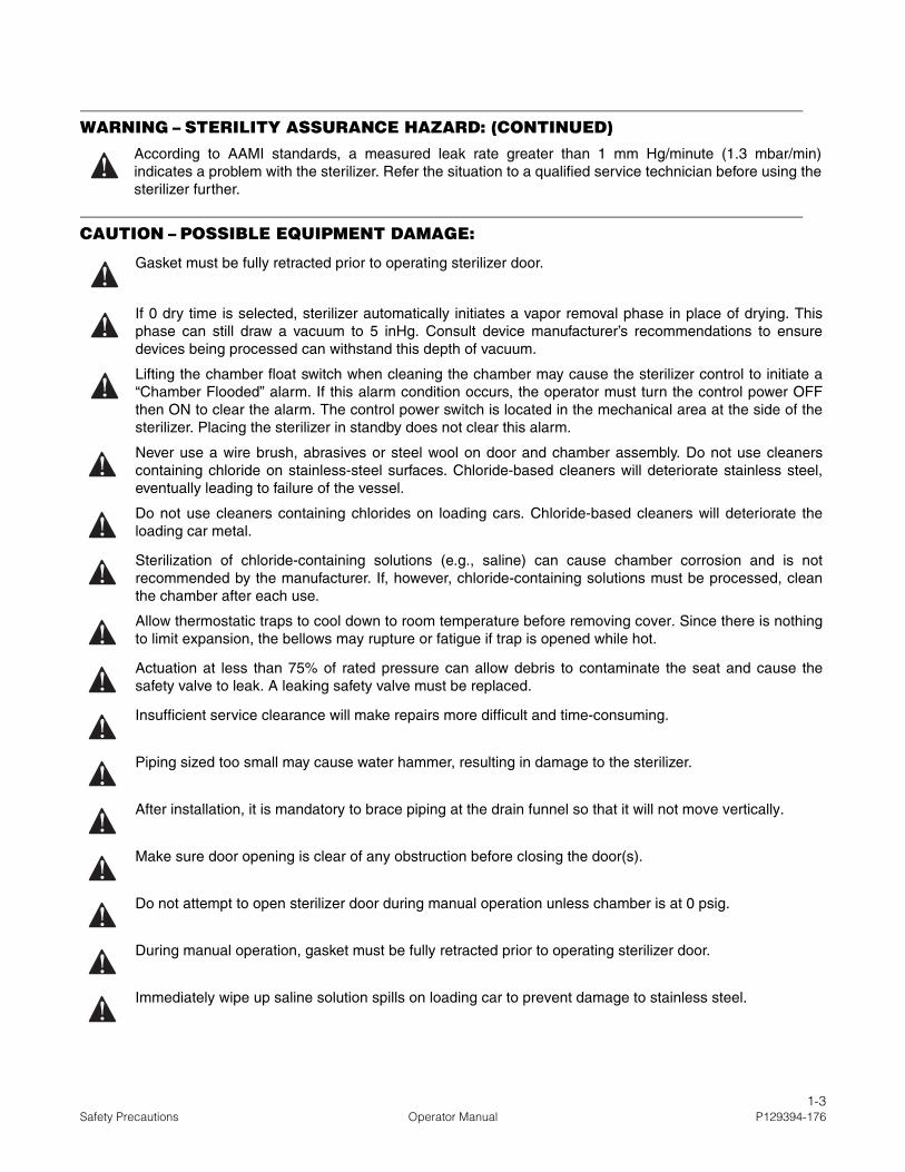
CAUTION – POSSIBLE EQUIPMENT DAMAGE:
According to AAMI standards, a measured leak rate greater than 1 mm Hg/minute (1.3 mbar/min)indicates a problem with the sterilizer. Refer the situation to a qualified service technician before using thesterilizer further.
Gasket must be fully retracted prior to operating sterilizer door.
If 0 dry time is selected, sterilizer automatically initiates a vapor removal phase in place of drying. Thisphase can still draw a vacuum to 5 inHg. Consult device manufacturer’s recommendations to ensuredevices being processed can withstand this depth of vacuum.
Lifting the chamber float switch when cleaning the chamber may cause the sterilizer control to initiate a“Chamber Flooded” alarm. If this alarm condition occurs, the operator must turn the control power OFFthen ON to clear the alarm. The control power switch is located in the mechanical area at the side of thesterilizer. Placing the sterilizer in standby does not clear this alarm.
Never use a wire brush, abrasives or steel wool on door and chamber assembly. Do not use cleanerscontaining chloride on stainless-steel surfaces. Chloride-based cleaners will deteriorate stainless steel,eventually leading to failure of the vessel.
Do not use cleaners containing chlorides on loading cars. Chloride-based cleaners will deteriorate theloading car metal.
Sterilization of chloride-containing solutions (e.g., saline) can cause chamber corrosion and is notrecommended by the manufacturer. If, however, chloride-containing solutions must be processed, cleanthe chamber after each use.
Allow thermostatic traps to cool down to room temperature before removing cover. Since there is nothingto limit expansion, the bellows may rupture or fatigue if trap is opened while hot.
Actuation at less than 75% of rated pressure can allow debris to contaminate the seat and cause thesafety valve to leak. A leaking safety valve must be replaced.
Insufficient service clearance will make repairs more difficult and time-consuming.
Piping sized too small may cause water hammer, resulting in damage to the sterilizer.
After installation, it is mandatory to brace piping at the drain funnel so that it will not move vertically.
Make sure door opening is clear of any obstruction before closing the door(s).
Do not attempt to open sterilizer door during manual operation unless chamber is at 0 psig.
During manual operation, gasket must be fully retracted prior to operating sterilizer door.
Immediately wipe up saline solution spills on loading car to prevent damage to stainless steel.
WARNING – STERILITY ASSURANCE HAZARD: (CONTINUED)
�
�
�
�
�
�
�
�
�
�
�
�
�
�
�
�
1-3Safety Precautions Operator Manual P129394-176

The following symbols appear on AMSCO® C Series Small Steam Sterilizers and are provided here for reference.
Table 2-1. Symbol Definitions
Symbol Definition Symbol Definition
Transfer of heat, hot surface
Serial number of unit (located on sterilizer’s
data plate)
Protective earth (i.e., ground)
V Voltage rating of unit
Electrostatic sensitive device
~ Alternating current
Locked cycle or machine set up option
A Amperage rating of unit
Unlocked cycle or machine set up option
Hz Frequency rating of unit
Attention, consult manual for further instructions Ø Phase of the unit
SN
SYMBOL DEFINITIONS
Symbol Definitions Operator Manual
2
2-1P129394-176
An Equipment Drawing showing all utility and space requirementswas supplied with the sterilizer. Clearance space shown on thedrawing is necessary for ease of installation and to assure properoperation and maintenance of equipment. Uncrating and InstallationInstructions were also furnished with the sterilizer. If any of thesedocuments are missing or misplaced, contact STERIS Corporationand provide the serial and model numbers of the equipment.Replacement copies will be sent to you promptly.
3.1 InstallationChecklist
After installing this unit according to the instructions provided,complete the following checklist to assure that your installation iscomplete and correct. Or, if you desire, contact STERIS for atechnician to be scheduled to test your installation and demonstrateproper equipment operation.
3.1.1 Service Clearance ❑ Clearance as specified on the equipment drawing must beavailable.
3.1.2 Plumbing Services ❑ Feed Water:
❑ All supply line shutoffs must be provided with lockoutcapability.
❑ Back flow prevention device installed.
NOTE: STERIS does not provide a backflow preventiondevice with the sterilizer.
❑ Water Pressure – measured (specification is 30 to 50 psig[2.1 to 3.5 bar], dynamic). Water pressure supplied must bewithin specifications as shown on the Equipment Drawing. Ifpressure is too high, a regulator must be installed. If waterpressure is too low, equipment performance will be affected.
❑ Water Quality – supplied must be within specifications.Improper water quality adversely affects equipmentoperation. Damage to the equipment due to improper waterquality is not covered under warranty.
❑ Steam Supply:
❑ Shutoffs (with provisions for lockout and tagout) locatednearby.
❑ Supply piping adequately sized.
❑ Supply pressure measured (specification is 50 to 80 psig[3.5 to 5.52 bar], dynamic).
❑ Drain Piping must be sloped properly, and sized to handle themaximum waste flow from the sterilizer.
CAUTION – POSSIBLE EQUIPMENT DAMAGE: Insufficient service clearance will make repairs more difficult and time-consuming.
�
CAUTION – POSSIBLE EQUIPMENT DAMAGE: Piping sized too small may cause water hammer, resulting in damage to the sterilizer.
�
CAUTION – POSSIBLE EQUIPMENT DAMAGE: After installation, it is mandatory to brace piping at the drain funnel so it will not move vertically.
�
INSTALLATION VERIFICATION
Installation Verification Operator Manual P
3
3-1129394-176

3.1.3 Electrical Service ❑ Electric single-phase service to the unit must be as specified onthe Equipment Drawing and on the Sterilizer’s Data Plate.
❑ Electric single-phase service requires a clearly markeddisconnect with lockout/tagout capability located near thesterilizer and installed according to local codes.
❑ Electric single-phase service should be on a separate circuit,and not tied into circuits containing large reactive loads (e.g.,motors).
❑ The protective earth ground must be connected to terminalblock TB-1 in the sterilizer power box.
3.1.4 Sterilizer Final Check ❑ Chamber leveled properly.
❑ Door opens and closes smoothly.
❑ Door locked switches adjusted correctly.
❑ Chamber strainer in place.
❑ Rack and shelves and/or loading car operates correctly.
❑ Paper loaded in printer.
❑ Printer ribbon properly installed.
❑ Warranty labels properly applied.
3.1.5 Cycle Operation ❑ Unit powers up correctly.
❑ Run Leak Test cycle – leak rate is to be less than 1.0 mm Hg/minute (1.3 mbar/min).
❑ Verify operation of a typical cycle (270°F [132° C] prevacuum).
WARNING – EXPLOSION HAZARD: This sterilizer is not designed to process flammable compounds.
�
3-2P129394-176 Operator Manual Installation Verification

3.2 TechnicalSpecifications
3.2.1 Overall Size • 16" Sterilizer: 26" wide x 74-1/2" high x 35-3/4" deep(660 mm wide x 1892 mm high x 908 mm deep)
• 20" Sterilizer: 30" wide x 74-1/2" high x 45-1/8" deep(762 mm wide x 1892 mm high x 1146 mm)
3.2.2 Weight(Fully Loaded)
• 16" Sterilizer:Single Door, Steam 750 lb (340 kg)Double Door, Steam 989 lb (449 kg)Single Door, Electric 890 lb (404 kg)
• 20" Sterilizer:Single Door, Steam 1231 lb (558 kg)Double Door, Steam 1606 lb (728 kg)Single Door, Electric 1371 lb (622 kg)Double Door, Electric 1726 lb (782 kg)
3.2.3 Utility Requirements • Electric:Direct Steam: 120 Volt, 50/60 Hz, 1-phase, 9.5 Amps
Steam Generator: 208 Volt, 50/60 Hz, 3-phase, 83.2 Amps; 240 Volt, 50/60 Hz, 3-phase, 72.2 Amps; or 480 Volt, 50/60 Hz, 3-phase, 37 Amps(if equipped)
• Water: Pressure:
Sterilizer 30 to 50 psig (2.1 to 3.5 bar)Steam Generator 20 to 50 psig (1.4 to 3.5 bar)
(if equipped)
Temperature:Sterilizer 70°F (21°C) maximum
Steam Generator 140°F (60°C) optimum, (if equipped) 150°F (66°C) maximum
Consumption:Sterilizer 6.0 gpm (23 lpm)Steam Generator 6.0 gpm (23 Ipm)
(if equipped)
• Steam:Pressure: 50 to 80 psig (3.5 to 5.2 bar)
• Consumption:16" Direct Steam 83 lb/hr (38 kg/h)20" Direct Steam 116 lb/hr (53 kg/hr)
3.2.4 EnvironmentalConditions
Temperature: 41 - 104°F (5 - 40°C)
Humidity: 85% noncondensing, maximum
Pollution Degree: 2
Installation Category (Overvoltage Category): II
A-Weighted Sound Power Level: 68 dBA (mean) -78 dBA (maximum)
3-3Installation Verification Operator Manual P129394-176

4.1 General The information in this section is intended as a general guide tosteam sterilization techniques. Also recommended is reference tothe standards of the Association for the Advancement of MedicalInstrumentation (AAMI ST-46), Steam Sterilization and SterilityAssurance, 3rd Edition.
• Prior to sterilization, all materials and articles must be thoroughlycleaned.
• After sterilization, goods should be stored in conditions that willnot compromise the barrier quality of their wrapping materials.
Important: Applicable cycles have been validated to satisfy therequirements outlined in Table 4-1 and Table 4-2. If cycleparameters (sterilize time, dry time, temperature) other than thoselisted are required, it is the responsibility of the healthcare facility toconsult and follow the device manufacturer’s written instructions.
NOTE: Contact STERIS® for information on a wide range ofeducation/ training programs designed to meet the educational needsof healthcare industries.
As part of the operator’s verification of the sterilization process,biological indicators may be used to demonstrate that sterilizationconditions have been met.
NOTE: Contact STERIS for information on specific biologicalindicators recommended for use with this sterilizer.
WARNING: The liquid cycle is for non-patient contact use only.
�
Cycle Default Status:
Factory-Default
Optional (Supervisor Access Only)
Table 4-1. AMSCO® C Series Prevacuum Sterilizer Cycles
Cycles: Sterilize Temp.
Sterilize Time
Dry Time
Recommended Load Refer to Table 4 (page iii) for Recommended Quantities
Validation Standard
Prevac Cycle 270°F (132°C)
4 Minutes 20 Minutes* Fabric Packs ST-8:2008
Prevac Cycle 270°F (132°C)
4 Minutes 30 Minutes Double-wrapped instrument trays, porous and non-porous loads. Maximum weight per tray, 25 lb (11.3 kg)
ST-8:2008
Prevac Cycle 270°F (132°C)
4 minutes 5 Minutes Single Fabric Pack ST-8:2008
Prevac Cycle 275°F (135°C)
3 Minutes 30 Minutes Double-wrapped instrument trays, porous and non-porous loads. Maximum weight per tray, 25 lb (11.3 kg)
ST-8:2008
TECHNIQUES OF STERILIZATION
Techniques of Sterilization Operator Manual P
4
4-1129394-176
Immediate UsePrevac Cycle
270°F (132°C)
4 Minutes 1 Minute Unwrapped instrument tray containing a single instrument, or multiple unwrapped instrument trays, porous and non-porous loads. Maximum weight per tray: 25 lb (11.3 kg)
ST-8:2008
Gravity Cycle 250°F (121°C)
30 Minutes 15 Minutes Fabric Packs ST-8:2008
Gravity Cycle 270°F (132°C)
15 Minutes 30 Minutes Double-wrapped instrument trays, non-porous load. Maximum weight per tray, 25 lb (11.3 kg)
ST-8:2008
Gravity Cycle 250°F (121°C)
30 Minutes 30 Minutes Double-wrapped instrument trays, non-porous load. Maximum weight per tray, 25 lb (11.3 kg)
ST-8:2008
Gravity Cycle 270°F (132°C)
25 Minutes 15 Minutes Fabric Packs ST-8:2008
Immediate Use Gravity Cycle
270°F (132°C)
3 Minutes 1 Minute Unwrapped instrument tray containing a single instrument; or multiple unwrapped instrument trays, non-porous load. Maximum weight per tray, 25 lb (11.3 kg)
ST-8:2008
Immediate Use Gravity Cycle
270°F (132°C)
10 Minutes 1 Minute ST-8:2008
Liquid Cycle 250°F (121°C)
45 Minutes N/A Refer to Table 5 (page iv) for recommended quantities
ST-8:2008
6. Leak Test** N/A N/A N/A None ST-8:2008
7. Dart Test** 270°F (132°C)
3-1/2 Minutes
1 Minute Dart or Bowie-Dick Test Pack ST-8:2008
8. Dart Warm-up** 270°F (132°C)
3 Minutes. 1 Minute None N/A
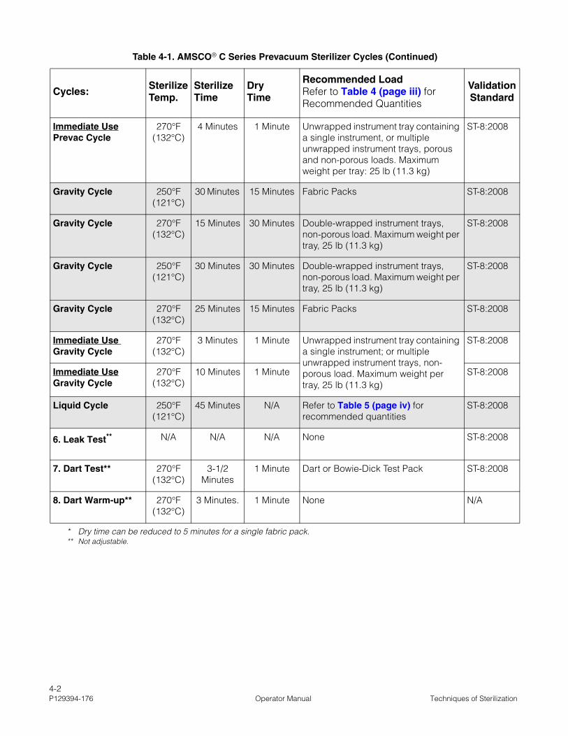
* Dry time can be reduced to 5 minutes for a single fabric pack. ** Not adjustable.
Table 4-1. AMSCO® C Series Prevacuum Sterilizer Cycles (Continued)
Cycles: Sterilize Temp.
Sterilize Time
Dry Time
Recommended Load Refer to Table 4 (page iii) for Recommended Quantities
Validation Standard
4-2P129394-176 Operator Manual Techniques of Sterilization

Table 4-2. AMSCO C Series SFPP Sterilizer Cycles
Cycles: Sterilize Temp.
Sterilize Time
Dry Time
Recommended Load Refer to Table 4 (page iii) for Recommended Quantities
Validation Standard
SFPP Cycle 270°F (132°C)
4 Minutes 30 Minutes Double-wrapped instrument trays, porous and non-porous loads. Maximum weight per tray, 25 lb (11.3 kg)
ST-8:2008
SFPP Cycle 270°F (132°C)
4 Minutes 20 Minutes Fabric Packs ST-8:2008
SFPP Cycle 275°F (135°C)
3 Minutes 30 Minutes* Double-wrapped instrument trays, porous and non-porous loads. Maximum weight per tray, 25 lb (11.3 kg)
ST-8:2008
SFPP Cycle 270°F (132°C)
4 Minutes 5 Minutes Single Fabric Pack ST-8:2008
Prevac Cycle 270°F (132°C)
4 Minutes 20 Minutes* Fabric Packs ST-8:2008
Prevac Cycle 270°F (132°C)
4 Minutes 30 Minutes Double-wrapped instrument trays, porous and non-porous loads. Maximum weight per tray, 25 lb (11.3 kg)
ST-8:2008
Prevac Cycle 270°F (132°C)
4 minutes 5 Minutes Single Fabric Pack ST-8:2008
Prevac Cycle 275°F (135°C)
3 Minutes 30 Minutes Double-wrapped instrument trays, porous and non-porous loads. Maximum weight per tray, 25 lb (11.3 kg)
ST-8:2008
Immediate UsePrevac Cycle
270°F (132°C)
4 Minutes 1 Minute Unwrapped instrument tray containing a single instrument, or multiple unwrapped instrument trays, porous and non-porous loads. Maximum weight per tray: 25 lb (11.3 kg)
ST-8:2008
Gravity Cycle 250°F (121°C)
30 Minutes 15 Minutes Fabric Packs ST-8:2008
Gravity Cycle 270°F (132°C)
15 Minutes 30 MinutesDouble-wrapped instrument trays. Maximum weight per tray, 25 lb (11.3 kg)
ST-8:2008
Gravity Cycle 250°F (121°C)
30 Minutes 30 Minutes ST-8:2008
4-3Techniques of Sterilization Operator Manual P129394-176
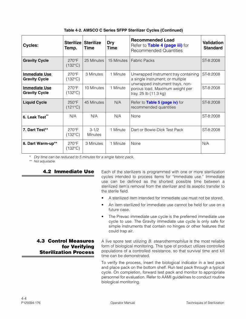
4.2 Immediate Use Each of the sterilizers is programmed with one or more sterilizationcycles intended to process items for “immediate use.” Immediateuse can be defined as the shortest possible time between asterilized item’s removal from the sterilizer and its aseptic transfer tothe sterile field.
• A sterilized item intended for immediate use must not be stored.
• An item sterilized for immediate use cannot be held for use on afuture case.
• The Prevac immediate use cycle is the preferred immediate usecycle to use. The Gravity immediate use cycle is only safe forsimple instruments that contain no hinges or other features thatcould trap air.
4.3 Control Measuresfor Verifying
Sterilization Process
A live spore test utilizing B. stearothermophilus is the most reliableform of biological monitoring. This type of product utilizes controlledpopulations of a controlled resistance, so that survival time and killtime can be demonstrated.
To verify the process, insert the biological indicator in a test packand place pack on the bottom shelf. Run test pack through a typicalcycle. On completion, forward test pack and monitor to appropriatepersonnel for evaluation. Refer to AAMI guidelines to conduct routinebiological monitoring.
Gravity Cycle 270°F (132°C)
25 Minutes 15 Minutes Fabric Packs ST-8:2008
Immediate Use Gravity Cycle
270°F (132°C)
3 Minutes 1 Minute Unwrapped instrument tray containing a single instrument; or multiple unwrapped instrument trays, non-porous load. Maximum weight per tray, 25 lb (11.3 kg)
ST-8:2008
Immediate Use Gravity Cycle
270°F (132°C)
10 Minutes 1 Minute ST-8:2008
Liquid Cycle 250°F (121°C)
45 Minutes N/A Refer to Table 5 (page iv) for recommended quantities
ST-8:2008
6. Leak Test** N/A N/A N/A None ST-8:2008
7. Dart Test** 270°F (132°C)
3-1/2 Minutes
1 Minute Dart or Bowie-Dick Test Pack ST-8:2008
8. Dart Warm-up** 270°F (132°C)
3 Minutes 1 Minute None N/A
* Dry time can be reduced to 5 minutes for a single fabric pack. ** Not adjustable.
Table 4-2. AMSCO C Series SFPP Sterilizer Cycles (Continued)
Cycles:Sterilize Temp.
Sterilize Time
Dry Time
Recommended Load Refer to Table 4 (page iii) for Recommended Quantities
Validation Standard
4-4P129394-176 Operator Manual Techniques of Sterilization
4-5
4.3.1 Biological Monitors Tests such as the Dart® (Daily Air Removal Test) or Bowie-Dick aredesigned to document the removal of residual air from a samplechallenge load.
Run a Dart (Bowie-Dick test) cycle daily before processing any loadsin a sterilizer equipped with prevacuum cycles. The first prevacuumcycle of each day should be used to test the adequacy of air removalfrom the chamber and load, so that steam can penetrate the load. Itis not a test for adequate exposure to heat in terms of time-at-temperature.
4.3.2 Testing for PrevacuumEfficiency
In the case of these tests, following exposure in a prevacuumsterilizing cycle, the pack is opened, the indicator examined, andconclusions are drawn as to the pattern of residual air, if any, thatremained in the pack during the sterilizing cycle. Any indication of amalfunction must be reported to the supervisor. Sterilizer must not beused again until approved by supervisor.
4.4 Dart (Bowie-Dick)Test
The Dart (Bowie-Dick) Test is designed to document the removal ofresidual air from a sample challenge load in a prevacuum sterilizer.This test does not apply to gravity, liquids or SFPP cycles.
In the case of this test, following exposure in a prevacuum test cycle,the pack is opened, the indicator examined and conclusions aredrawn as to the pattern of residual air, if any, that remained in thepack during the sterilizing cycle. Any indication of a malfunctionmust be reported to the supervisor. Sterilizer must not be used to runprevacuum cycles until approved by supervisor.
According to AAMI ST-79, a steam penetration test shall be carriedout at the beginning of each day the sterilizer is to be used. Refer toinstructions for running the Dart test cycle in SECTION 6, STERILIZER
OPERATION. Dart test packs are designed to expose the pattern anddocument the removal of residual air from the sample load. Any testpackage must be constructed in accordance with instructions givenin the AAMI ST-46 standard.
NOTE: The Dart test cycle is not a test for adequate exposure to heatin terms of time-at-temperature.
WARNING – STERILITY ASSURANCE HAZARD: Load sterility may be compromised if the biological indicator or vacuum leak test indicates a potential problem. If these indicators show a potential problem, refer the situation to a qualified service technician before using the sterilizer further.
�
WARNING – STERILITY ASSURANCE HAZARD: Load sterility may be compromised if the biological indicator or vacuum leak test indicates a potential problem. If these indicators show a potential problem, refer the situation to a qualified service technician before using the sterilizer further.
�
Techniques of Sterilization Operator Manual P129394-176

4.5 Vacuum Leak Test The Vacuum Leak Test (see appropriate cycle description inSECTION 6, STERILIZER OPERATION) measures the integrity of thesealed pressure vessel and associated piping to assure air is notbeing admitted to the sterilizer during the vacuum drawdowns.
After running a Leak Test cycle, a value or leak rate will be printed onthe printer tape. This value will help define a trend over a period oftime if the integrity of the system begins to deteriorate (i.e., allowingair to enter the system). By running a Leak Test cycle daily or weekly,the operator or maintenance personnel can always monitor the airtightness of the system and make repairs or adjustments whennecessary.
NOTE: A leak rate of greater than 1 mmHg per minute indicates aproblem with the sterilizer that must be addressed.
4.6 Recommendationsfor the Sterilization
Process
Process all goods using prevacuum cycles. The AMSCO C Seriessmall steam sterilizer is not a gravity displacement sterilizer. Rungravity cycles only when qualified personnel have evaluated theloads and determined the efficacy of a gravity cycle.
Saturated steam is a well controlled, reliable method for processingitems which can withstand the temperatures and pressuresassociated with steam sterilization. The requirements for achievingreproducible results are well known by many users, but are notalways understood.
The condition most likely to result in sterilization problems is a failureto completely remove air from items being sterilized. For example,placing an empty beaker or bowl in an upright position in a gravitydisplacement sterilizer may result in the object not being sterilized,or may require exceptionally long sterilization times. This problem iscaused by air trapped in the object; air has almost twice the densityof saturated steam under the same conditions. Thus, air remains inthe container’s bottom while steam forms a stable layer above it.(Similar to oil forming a stable layer over water.) As long as there isno mechanism for actively mixing air and steam, the bottom of thecontainer is only exposed to dry heat, which is not an effectivesterilization method at the time and temperatures typically used insteam processes.
The best method for enhancing sterilization of solid-bottomcontainers in gravity displacement cycles is to orient all objects in aposition which would allow water to flow out. When steam enters thechamber, it tends to layer over trapped air. If, however, an object isoriented so air is not trapped, but can flow out; air flows out to bereplaced by steam. Steam can now reach all surfaces and effectsterilization.
WARNING – STERILITY ASSURANCE HAZARD: Load sterility may be compromised if the biological indicator or vacuum leak test indicates a potential problem. If these indicators show a potential problem, refer the situation to a qualified service technician before using the sterilizer further.
�
4-6P129394-176 Operator Manual Techniques of Sterilization

4.7 Techniques ofSterilization for
Liquid Cycle
Important: The liquid cycle is for non-patient contact use only.
Refer to Table 4-3 for recommended Liquid cycle parameters. Therecommended times indicated in Table 4-3 assume the use ofvented bottles. Minimum recommended sterilization time (fourthcolumn) includes the time required to bring the solution up to thesterilize temperature plus the time required to achieve sterilization.
Table 4-3. Liquid Cycle Processing Guidelines
WARNING – EXPLOSION HAZARD: This sterilizer is not designed to process flammable compounds.
WARNING – PERSONAL INJURY HAZARD: Avoid personal injury from bursting bottles. Liquid sterilization cycle must only be used for liquids in borosilicate (Pyrex) flasks with vented closures.
WARNING: The liquid cycle is for non-patient contact use only.
WARNING – BURN HAZARD: When sterilizing liquids, you must observe the following procedures:
• Use Liquid cycle only.
• Use only vented closures.
• Use only Type I borosilicate glass bottles.
• Do not allow hot bottles to be jolted.
• Steam may be released from the chamber when door is opened. Step back from the sterilizer each time the door is opened to minimize contact with steam vapor.
CAUTION – POSSIBLE EQUIPMENT DAMAGE: Sterilization of chloride-containing solutions (e.g., saline) can cause chamber corrosion and is not recommended by the manufacturer. If, however, chloride-containing solutions must be processed, clean the chamber after each use.
�
�
�
�
�
Sterilizer Size
Number of Containers
for Full Load
Volume of Liquid in
One Container
Minimum Recommended Sterilize Time
at 250°F (121°C) in minutes
16 x 16 x 26"(406 x 406 x 660 mm)
15
1000 mL 45
20 x 20 x 38” (508 x 508 x 965 mm)with Loading Car
32
20 x 20 x 38” (508 x 508 x 965 mm) with Rack and Shelves
28
4-7Techniques of Sterilization Operator Manual P129394-176

4.8 Recommendationsfor Sterilizing Liquids
Important: Read the following paragraphs before sterilizing anyliquids in your sterilizer. The liquid cycle is for non-patient contactuse only.
Borosilicate glass is required because it is a superior glass capableof resisting thermal shock. If glass not as thermally resistant is used,a greater potential for bursting exists.
Vented closures are required because, by design, they releaseinternal pressure build-up by automatically venting the containers,whereas pressure in unvented containers remains until the contentshave cooled. Examples of vented closures are shown in Figure 4-1.
When loading, place small bottles in a separate basket to minimizesliding. Always use side rails on the loading car to preventcontainers or baskets from falling off.
Figure 4-1. Vented Closures
4.9 Sterilization ofImplantable Devices
A healthcare facility must develop adequate monitoring practices forthe sterilization of implantable devices. Refer to AORNrecommended practices for more information.
Sterilization of implantable devices by a healthcare facility must bemonitored:
• When sterilizing an implantable device, always place abiological monitor in the load.
• Following sterilization, implant must be quarantined until thebiological monitor has been incubated and read by a qualifiedperson.
WARNING – EXPLOSION HAZARD: The liquid cycle is for non-patient contact use only.
WARNING – PERSONAL INJURY HAZARD: Avoid personal injury from bursting bottles. Liquid sterilization cycle must only be used for liquids in borosilicate (Pyrex) flasks with vented closures.
WARNING – BURN HAZARD: When sterilizing liquids, you must observe the following procedures:
• Use Liquid cycle only.
• Use only vented closures.
• Use only Type I borosilicate glass bottles.
• Do not allow hot bottles to be jolted.
• Steam may be released from the chamber when door is opened. Step back from the sterilizer each time the door is opened to minimize contact with steam vapor.
CAUTION – POSSIBLE EQUIPMENT DAMAGE: Sterilization of chloride-containing solutions (e.g., saline) can cause chamber corrosion and is not recommended by the manufacturer. If, however, chloride-containing solutions must be processed, clean the chamber after each use.
�
�
�
�
Before Sterilization
After Sterilization
Morton Closure
Tab
Tab
Morton Closure
Morton Closure
4-8P129394-176 Operator Manual Techniques of Sterilization
5-1Component Identification Operator Manual P129394-176
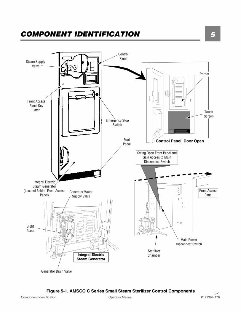
Figure 5-1. AMSCO C Series Small Steam Sterilizer Control Components
JACKET
CHAMBER
Generator Drain Valve
Sight Glass
Control Panel, Door Open
Main Power Disconnect Switch
Printer
Touch Screen
Generator Water Supply Valve
Foot Pedal
Emergency Stop Switch
Front Access Panel Key
Latch
Steam Supply Valve
Integral ElectricSteam Generator
Integral ElectricSteam Generator
(Located Behind Front Access Panel)
Front Access Panel
SterilizerChamber
Swing Open Front Panel and Gain Access to Main Disconnect Switch
Control Panel
COMPONENT IDENTIFICATION
5
5.1 General Use this manual to become familiar with control locations andfunctions before operating the sterilizer (refer to Figure 5-1). Thecontrols for this sterilizer are contained within the control touchscreen. Control touchpads appear on the screen as needed duringeach operation. Available controls change as the sterilizer stepsthrough different operations.
5.2 Main Sterilizer andCycle Controls
• Main Power Disconnect Switch (refer to Figure 5-1) – Locatedon the sterilizer’s main control box (right-hand side as facingoperating end), this switch disconnects power to the control.Under normal operation, this switch is left in the ON position at alltimes, and accessed only when servicing the sterilizer.
• Steam Supply Valve – This is located behind the side accesspanel (or within the wall enclosure), above the chamber. Refer toFigure 5-2. Ensure this is in the open position before trying tooperate the sterilizer.
• Water Supply Valve – This is located behind the side accesspanel (or within the wall enclosure, below the chamber. Refer to .Ensure this is in the open position before trying to operate thesterilizer.
• Chamber Emergency Manual Exhaust Valve – Used only inemergency situations, the valve is to be left in the closed positionfor normal operation. Refer to SECTION 5, EMERGENCY DOOR
OPENING PROCEDURE.
• Sterilizer Control Touchpad – This is visible on the controltouch screen whenever the sterilizer is in Standby mode. Refer toSECTION 5.5, OPERATING END CONTROL PANEL ON PAGE 5-6 formore information.
5-2P129394-176 Operator Manual Component Identification

.
NOTE: Touch-screen pads respond to very slight pressure, andonly need to be pressed lightly.
The sterilizer enters operating mode when the ON touchpad ispressed. This touchpad switches the sterilizer control betweenStandby and Ready conditions. Standby mode is usually usedwhen the sterilizer is not being operated – steam is turned offand machine cools, saving energy.
A screen reference number appears in the upper right corner ofeach display. Numbers are used for reference only, and do not relateto the operating sequence of the screen.
Figure 5-2. Basic Controls
STATUS . . STANDBY 0
TIME . . . 10:20:00 AM
DATE . . . 2/20/94
ON
Steam Supply Valve
Water Supply Valve
Standby Screen
5-3Component Identification Operator Manual P129394-176

5-4
5.3 ControlDisplays
Control displays can be divided into two categories, those occurringwhen the sterilizer is “out-of-cycle” and those occurring when thesterilizer is “in-cycle.”
Typical out-of-cycle and in-cycle displays are shown in Figure 5-3:
• Out-of-cycle displays are used to start cycles, or set up andadjust sterilizer operation. With the exception of the cyclestarting displays, most out-of-cycle displays will only be usedoccasionally. Detailed instructions for adjusting the sterilizeroperating parameters are in Section 7, Cycle and Control ValueProgramming.
• Generally, when the sterilizer is in-cycle, displays appearautomatically and, unless an abnormal condition occurs, requireno special attention or instructions. In-cycle displays tell theoperator at what temperature and pressure the sterilizerchamber is operating, show the current cycle phase, andindicate when the processing cycle is complete. For more detailsabout operating cycles, refer to Section 6, Sterilizer Operation.
Figure 5-3. Typical Out-Of-Cycle and In-Cycle Displays
STATUS . . DOOR CLOSED 1
TEMP . . . 128 F
PRESS . . 0 PSIG
PRESS "MORE CYCLES" FOR GRAVITY & TEST.
1.270°F 2.270°F 3.275°F 4.270°FPREVAC PREVAC PREVAC PREVAC
S=04 D=01 S=04 D=30 S=03 D=30 S=04 D=20
IMMEDIATE FULL LOAD FULL LOAD FULL LOAD
USE TRAY TRAY FABRIC
10:20:34 AM 10/08/10
STANDBYMENUPAPERFEED
MORECYCLES
STATUS . .PURGE 1:00 4
TEMP . . .124 F
PRESS . . .0 psig
3.TRAY, PREVAC, 270F, 4, 30
PROJECTED CYCLE COMPLETION TIME:
15:20MINUTES SECONDS
PAPER STATUSFEED PRINT ABORT
Out-of-Cycle In-Cycle
P129394-176 Operator Manual Component Identification

5.4 Alarm Displays Alarm displays tell operators and technicians when the sterilizer isexperiencing an abnormal condition. Alarm conditions can becaused by failure of utility supplies or sterilizer components.SECTION 9, TROUBLESHOOTING details the steps an operator can taketo solve most alarm conditions. Example alarm displays are shown inFigure 5-4.
When an alarm occurs during cycle operation, a display appears onthe screen, accompanied by an audible tone. This display indicatesthe problem as determined by control sensors, and lists a brieftroubleshooting list. The operator should follow the instructions onthe screen, if possible. If these instructions fail to clear the alarm,consult your departmental supervisor or a trained service technicianbefore using the sterilizer further.
Figure 5-4. Alarm Display Examples
STATUS . .ALARM 205
TOO LONG IN CHARGE
CHAMBER . .158.0F 0psig
STERILIZER WILL:AUTOMATICALLY TRY TO COMPLETE CYCLEOPERATOR INSTRUCTIONS:1. SILENCE ALARM2. CHECK STEAM SUPPLY VALVE
->IF CLOSED, OPEN VALVE3. IF ALARM RECURS, CALL SERVICE
SILENCE STATUS PAPER SERVICEALARM PRINT FEED HELP
STATUS. . ALARM 206
TOO LONG IN CHARGE
CHAMBER DID NOT REACH STERILIZETEMPERATURE WITHIN ALLOTTED TIME
CAUSES AND CORRECTION:1. STEAM PRESSURE LESS THAN 50 PSIG
->CHECK STEAM SUPPLY PIPING2. STEAM REGULATOR MALFUNCTION
->REPAIR2. SOLENOID VALVE MALFUNCTION
->REPAIR S09->REPAIR S02
3. CONTROL OUT OF CALIBRATION->RECALIBRATE (CONTACT QUALIFIED SERVICE PERSON)
PAPERFEED EXITABORT
Alarm Notification Screen Alarm Service Information Screen
5-5Component Identification Operator Manual P129394-176

5.5 Operating EndControl Panel
A sterilizer equipped with two doors will also be equipped with twocontrol panels. The control panel at the loading door of the sterilizeris referred to as the “operating end control” (OE control); the controlpanel located at the unloading door is referred to as the “non-operating end control” (NOE control).
A single-door sterilizer is equipped with an “operating end control”only.
NOTE: Except for the presence of the printer (which is only present atthe operating end of the unit), control panels at both ends of the unitare similar and each can be used to start or abort the sterilizer.
The operating end control panel (see Figure 5-5) is used to:
• Select and start cycles
• Abort cycles
• Set cycles and cycle values
• Obtain status printouts (see “Printer” paragraph later in thissection)
The operating end control includes a printer for cycledocumentation.
Cycle status and control messages are shown on a 30 line x40 column graphics display. Cycles can be started or aborted usingthe touch screen pads. Cycles and cycle values can be set using theChange Values procedure (accessible from the sterilizer MENUscreen). If changing cycle values becomes necessary, refer toSection 7, Cycle and Control Value Programming of this manual.
5-6P129394-176 Operator Manual Component Identification
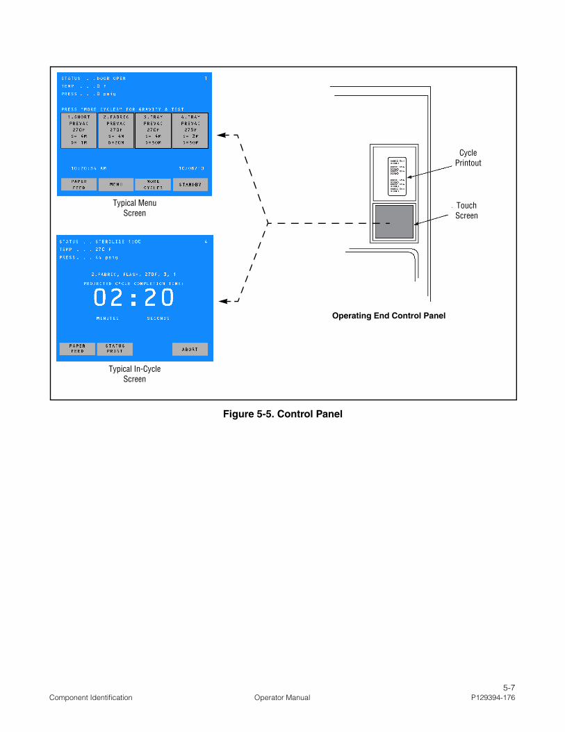
Figure 5-5. Control Panel
Operating End Control Panel
Cycle Printout
Touch Screen
Typical Menu Screen
Typical In-Cycle Screen
5-7Component Identification Operator Manual P129394-176
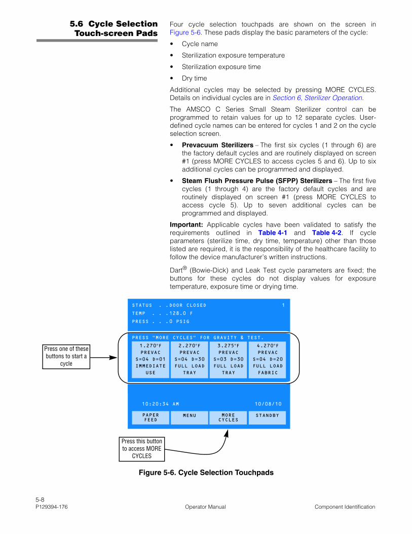
5.6 Cycle SelectionTouch-screen Pads
Four cycle selection touchpads are shown on the screen inFigure 5-6. These pads display the basic parameters of the cycle:
• Cycle name
• Sterilization exposure temperature
• Sterilization exposure time
• Dry time
Additional cycles may be selected by pressing MORE CYCLES.Details on individual cycles are in Section 6, Sterilizer Operation.
The AMSCO C Series Small Steam Sterilizer control can beprogrammed to retain values for up to 12 separate cycles. User-defined cycle names can be entered for cycles 1 and 2 on the cycleselection screen.
• Prevacuum Sterilizers – The first six cycles (1 through 6) arethe factory default cycles and are routinely displayed on screen#1 (press MORE CYCLES to access cycles 5 and 6). Up to sixadditional cycles can be programmed and displayed.
• Steam Flush Pressure Pulse (SFPP) Sterilizers – The first fivecycles (1 through 4) are the factory default cycles and areroutinely displayed on screen #1 (press MORE CYCLES toaccess cycle 5). Up to seven additional cycles can beprogrammed and displayed.
Important: Applicable cycles have been validated to satisfy therequirements outlined in Table 4-1 and Table 4-2. If cycleparameters (sterilize time, dry time, temperature) other than thoselisted are required, it is the responsibility of the healthcare facility tofollow the device manufacturer’s written instructions.
Dart® (Bowie-Dick) and Leak Test cycle parameters are fixed; thebuttons for these cycles do not display values for exposuretemperature, exposure time or drying time.
Figure 5-6. Cycle Selection Touchpads
STATUS . .DOOR CLOSED 1
TEMP . . .128.0 F
PRESS . . .0 PSIG
PRESS "MORE CYCLES" FOR GRAVITY & TEST.
1.270°F 2.270°F 3.275°F 4.270°FPREVAC PREVAC PREVAC PREVAC
S=04 D=01 S=04 D=30 S=03 D=30 S=04 D=20
IMMEDIATE FULL LOAD FULL LOAD FULL LOAD
USE TRAY TRAY FABRIC
10:20:34 AM 10/08/10
STANDBYMENUPAPERFEED
MORECYCLES
Press one of these buttons to start a
cycle
Press this button to access MORE
CYCLES
5-8P129394-176 Operator Manual Component Identification
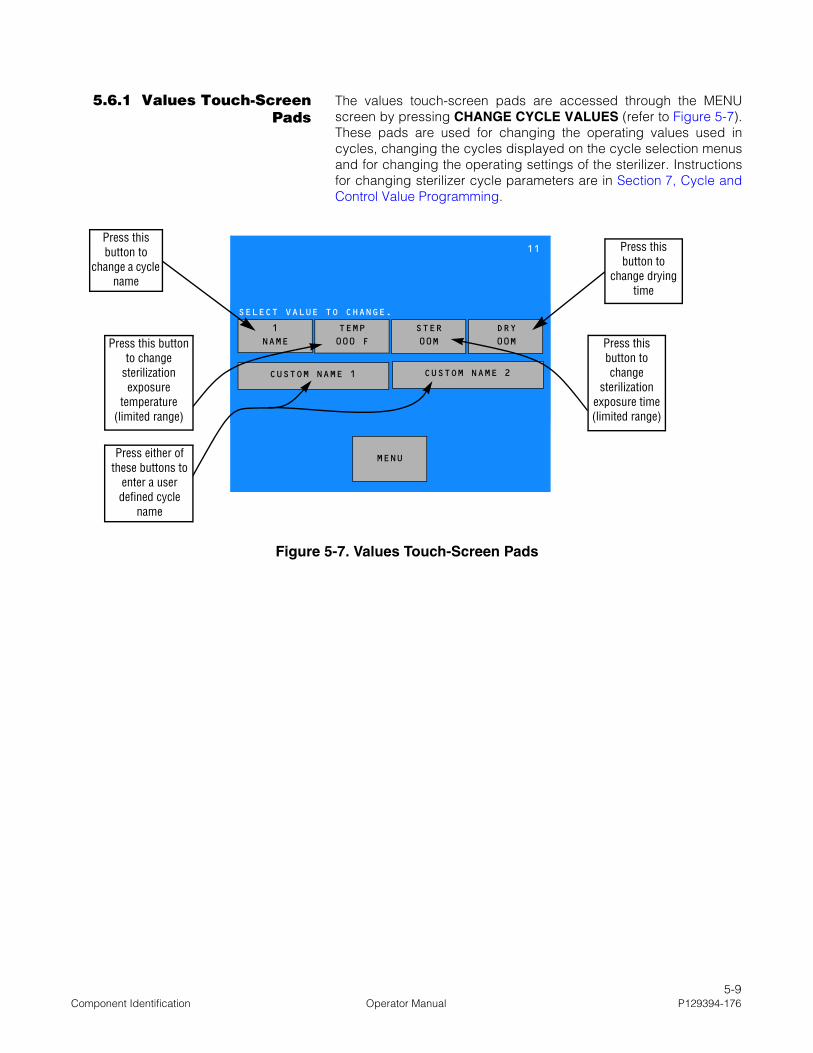
5.6.1 Values Touch-ScreenPads
The values touch-screen pads are accessed through the MENUscreen by pressing CHANGE CYCLE VALUES (refer to Figure 5-7).These pads are used for changing the operating values used incycles, changing the cycles displayed on the cycle selection menusand for changing the operating settings of the sterilizer. Instructionsfor changing sterilizer cycle parameters are in Section 7, Cycle andControl Value Programming.
Figure 5-7. Values Touch-Screen Pads
SELECT VALUE TO CHANGE.
1 TEMP STER DRY
NAME 000 F 00M 00M
11
MENU
Press this button to
change a cycle name
Press this button to change
sterilization exposure time (limited range)
Press this button to
change drying time
CUSTOM NAME 1 CUSTOM NAME 2
Press this button to change
sterilization exposure
temperature (limited range)
Press either of these buttons to
enter a user defined cycle
name
5-9Component Identification Operator Manual P129394-176

5.6.2 Abort Touch-ScreenPad
The Abort touch-screen pad is used to end a cycle before it finishesnormally. A cycle only needs to be aborted if an abnormal conditionor a control problem develops during the cycle. Pressing Abortcauses the sterilizer chamber to depressurize (if pressurized), or AirBreak (if in vacuum); the door seal deactivates, the control promptsthe operator to open the door and the sterilizer returns to its normalout-of-cycle state. If an abnormal condition persists after fullyaborting the cycle, contact your supervisor or a qualified servicetechnician before trying to operate the sterilizer further.
Figure 5-8. Cycle Abort Touch-Screen Pad
STATUS . . DRY 0:45 4
TEMP . . . 210.0 F
PRESS. . . 0.29 psig
3.TRAY, PREVAC, 270F, 4, 30
PROJECTED CYCLE COMPLETION TIME:
03:18MINUTES SECONDS
PAPER STATUSFEED PRINT ABORT
Press this button to abort
a cycle
5-10P129394-176 Operator Manual Component Identification

5.7 Printer Refer to Figure 5-9
Printer records all cycle data on 2-1/4" (57 mm) wide single-plypaper. See SECTION 8, ROUTINE MAINTENANCE for paper changingprocedure. Printer functions controlled by touch-screen pads are asfollows:
• Paper Feed – (appears on typical In-cycle screen) Press to feedout paper from the roll stored inside the control. Accessibleduring all phases of operation, including alarm conditions. Pressand hold for continuous feed.
• Status Print – (appears on typical In-cycle screen) Press toobtain a printout of current cycle phase and conditions (whenunit is in cycle). This touchpad is only visible during cycleoperation.
• Duplicate Print – (appears on Menu screen) Press to obtain acomplete duplicate printout of the last previously run cycle(when unit is not in cycle). This touchpad is only visible on thescreen during Complete and Change Values menu. TheDuplicate Print touch screen pad is not visible upon first power-up of the day.
Menu Screen
Typical In-Cycle Screen
5-11Component Identification Operator Manual P129394-176

5.8 Printouts Refer to Figure 5-9
The printout reports useful information about each cycle the sterilizerruns. This includes the load number, which is a unique identifyingcode. Each load number is printed in the following format:
• Two-digit month (e.g., April = 04)
• Two-digit day (e.g., twenty eighth day = 28)
• Two-digit daily cycle count (e.g., first cycle = 01, second = 02,etc.).
Example of a complete load number: “042801” (April 28, firstcycle).
During the cycle, status lines on the printouts show the time the linewas printed, chamber temperature and the level of vacuum orpressure in the chamber. Each status line also begins with a lettercode. This code indicates during which cycle phase the print lineoccurred, or what kind of event caused the print line to occur.
Refer to Figure 5-9 for other printout features.
5-12P129394-176 Operator Manual Component Identification

Figure 5-9. Typical Printout
Cycle Type
Cycle Start Time & Date
Cycle Count TotalOperator I.D.
Machine Number & SerialNumber
Sterilize TemperatureControl Overdrive Temperature
Sterilize TimeDry Time
Status Print Codes:Conditioning
• Charge• Vacuum Pulses
Sterilize
Exhaust & Dry
Complete
Load Number
Sterilize TemperatureMin./Max.
Time in Phase
Total Cycle Time
Additional Status Print Codes:F = Alarm (Failure)L = Leak Test (Vacuum or Hold)D = Demand Print (Print Status)
5-13Component Identification Operator Manual P129394-176
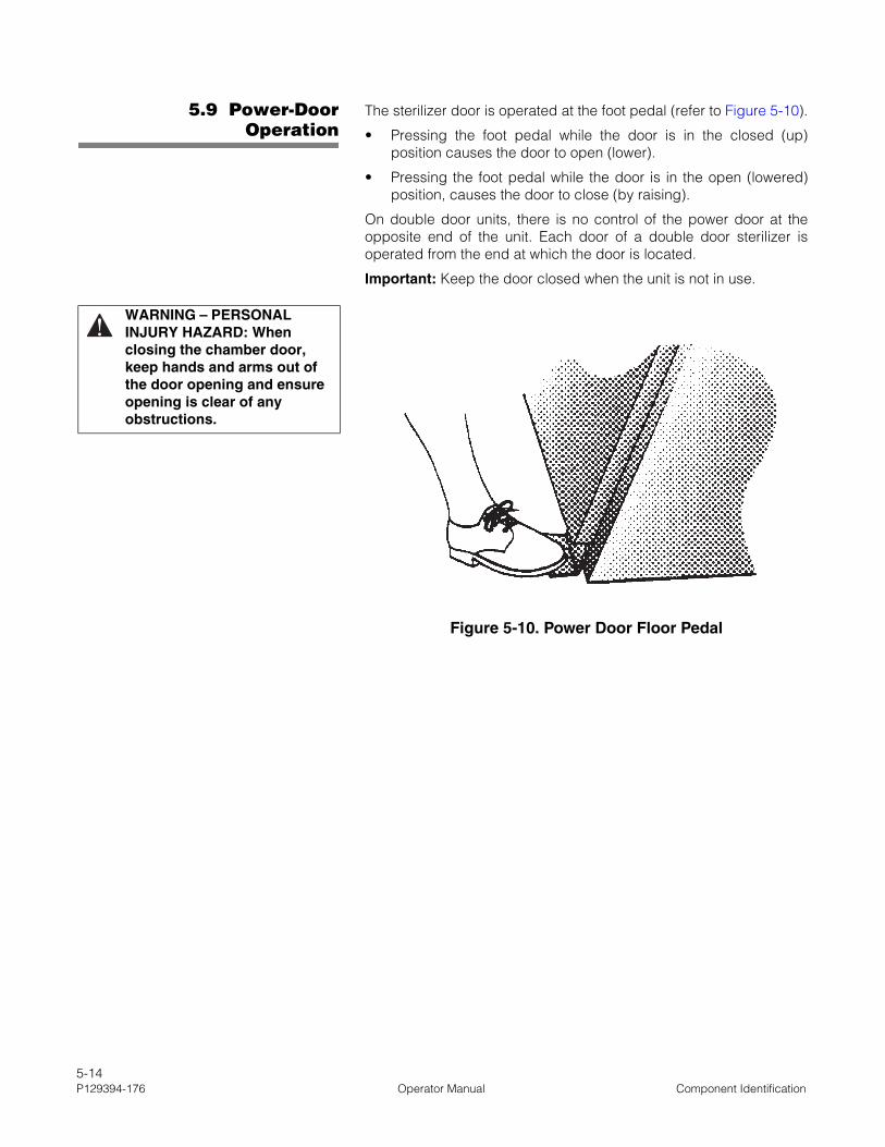
5.9 Power-DoorOperation
The sterilizer door is operated at the foot pedal (refer to Figure 5-10).
• Pressing the foot pedal while the door is in the closed (up)position causes the door to open (lower).
• Pressing the foot pedal while the door is in the open (lowered)position, causes the door to close (by raising).
On double door units, there is no control of the power door at theopposite end of the unit. Each door of a double door sterilizer isoperated from the end at which the door is located.
Important: Keep the door closed when the unit is not in use.
WARNING – PERSONAL INJURY HAZARD: When closing the chamber door, keep hands and arms out of the door opening and ensure opening is clear of any obstructions.
�
Figure 5-10. Power Door Floor Pedal
5-14P129394-176 Operator Manual Component Identification

5.10 Emergency DoorOpening Procedure
This procedure should only be used when pressure remains in thesterilizer chamber, and the door cannot be opened normallybecause the sterilizer has lost either electrical or water utilities.
• Use emergency door opening procedure to retrieve a loadtrapped in the chamber.
• This procedure requires pushing on the door cover to retract thedoor seal into the groove, then pushing the door downwardmanually.
Procedure:
1. Swing open the access panel of the sterilizer. Open the emergency exhaust hand valve until chamber exhausts to 0.0 psig. See Figure 5-11.
2. Using the door release tool provided, press on the upper left hand and right hand corners of the chamber door (see Figure 5-11). The door should give inward slightly, indicating that the seal has been pushed into the groove. The door must “bottom out” against the metal end-frame of the sterilizer chamber.
3. Close the access panel of the sterilizer.
4. Press down on the door handle to lower the door. The door will slide stiffly, so be prepared to press down hard.
Once the door is open, do not use the sterilizer until the unit has been examined by a qualified service technician. Further use without attention may damage the sterilizer.
5. Close the emergency exhaust valve.
Figure 5-11. Emergency Door Opening Procedure
WARNING – BURN HAZARD: Do not attempt to open sterilizer door if a water in chamber alarm condition exists.
�
Emergency Seal Retract Tool
Emergency Exhaust Valve
5-15Component Identification Operator Manual P129394-176

5.11 Emergency StopSwitch
An emergency stop switch (Figure 5-12) is a safety feature designedto shut the sterilizer down completely in an emergency situation.Pressing the emergency stop switch disconnects power to the doorand valves, causing the door to stop and most valves to close,except S1 and S40, which are normally open, and will open when theemergency stop switch is pressed.
Important: The emergency stop switch is for emergency use only!DO NOT USE AS A START/STOP SWITCH. To properly abort acycle, press abort button on sterilizer display.
Figure 5-12. Emergency Stop Switch, Key and Guard
Emergency Stop Label
Emergency Stop Switch
Emergency Stop Key
Emergency Stop Guard
Figure 5-13. Press Abort Button to EndCycles When Needed
STATUS . . CHARGE 4
TEMP . . . 261.0 F
PRESS . . 27.7 psig
3.TRAY, PREVAC, 270F, 4, 30
PROJECTED CYCLE COMPLETION TIME:
12:20MINUTES SECONDS
PAPER STATUSFEED PRINT ABORT
Abort Button –Press when necessary to
end cycle
5-16P129394-176 Operator Manual Component Identification
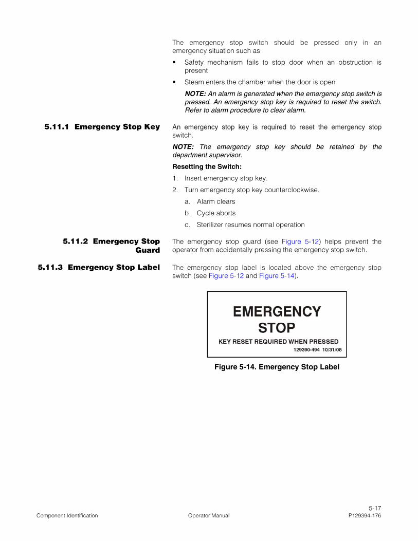
The emergency stop switch should be pressed only in anemergency situation such as
• Safety mechanism fails to stop door when an obstruction ispresent
• Steam enters the chamber when the door is open
NOTE: An alarm is generated when the emergency stop switch ispressed. An emergency stop key is required to reset the switch.Refer to alarm procedure to clear alarm.
5.11.1 Emergency Stop Key An emergency stop key is required to reset the emergency stopswitch.
NOTE: The emergency stop key should be retained by thedepartment supervisor.
Resetting the Switch:
1. Insert emergency stop key.
2. Turn emergency stop key counterclockwise.
a. Alarm clears
b. Cycle aborts
c. Sterilizer resumes normal operation
5.11.2 Emergency StopGuard
The emergency stop guard (see Figure 5-12) helps prevent theoperator from accidentally pressing the emergency stop switch.
5.11.3 Emergency Stop Label The emergency stop label is located above the emergency stopswitch (see Figure 5-12 and Figure 5-14).
Figure 5-14. Emergency Stop Label
5-17Component Identification Operator Manual P129394-176
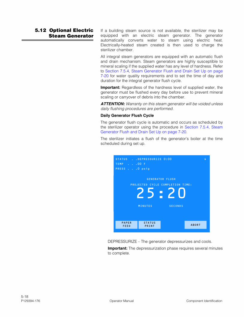
5.12 Optional ElectricSteam Generator
If a building steam source is not available, the sterilizer may beequipped with an electric steam generator. The generatorautomatically converts water to steam using electric heat.Electrically-heated steam created is then used to charge thesterilizer chamber.
All integral steam generators are equipped with an automatic flushand drain mechanism. Steam generators are highly susceptible tomineral scaling if the supplied water has any level of hardness. Referto Section 7.5.4, Steam Generator Flush and Drain Set Up on page7-20 for water quality requirements and to set the time of day andduration for the integral generator flush cycle.
Important: Regardless of the hardness level of supplied water, thegenerator must be flushed every day before use to prevent mineralscaling or carryover of debris into the chamber.
ATTENTION: Warranty on this steam generator will be voided unlessdaily flushing procedures are performed.
Daily Generator Flush Cycle
The generator flush cycle is automatic and occurs as scheduled bythe sterilizer operator using the procedure in Section 7.5.4, SteamGenerator Flush and Drain Set Up on page 7-20.
The sterilizer initiates a flush of the generator’s boiler at the timescheduled during set up.
DEPRESSURIZE – The generator depressurizes and cools.
Important: The depressurization phase requires several minutesto complete.
STATUS . .DEPRESSURIZE 0:00 4
TEMP . . .00 F
PRESS . . .0 psig
GENERATOR FLUSH
PROJECTED CYCLE COMPLETION TIME:
25:20MINUTES SECONDS
PAPER STATUSFEED PRINT ABORT
5-18P129394-176 Operator Manual Component Identification
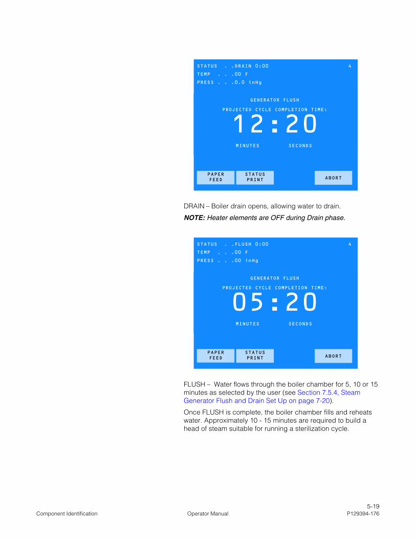
DRAIN – Boiler drain opens, allowing water to drain.
NOTE: Heater elements are OFF during Drain phase.
FLUSH – Water flows through the boiler chamber for 5, 10 or 15 minutes as selected by the user (see Section 7.5.4, Steam Generator Flush and Drain Set Up on page 7-20).
Once FLUSH is complete, the boiler chamber fills and reheats water. Approximately 10 - 15 minutes are required to build a head of steam suitable for running a sterilization cycle.
STATUS . .DRAIN 0:00 4
TEMP . . .00 F
PRESS . . .0.0 inHg
GENERATOR FLUSH
PROJECTED CYCLE COMPLETION TIME:
12:20MINUTES SECONDS
PAPER STATUSFEED PRINT ABORT
STATUS . .FLUSH 0:00 4
TEMP . . .00 F
PRESS . . .00 inHg
GENERATOR FLUSH
PROJECTED CYCLE COMPLETION TIME:
05:20MINUTES SECONDS
PAPER STATUSFEED PRINT ABORT
5-19Component Identification Operator Manual P129394-176

6.1 Before Operatingthe Sterilizer
Operate sterilizer by referring to the appropriate cycle description inthis section. The information in SECTION 6.1 through SECTION 6.7 aregeneral instructions that apply to all cycle operations.
1. Press ON touch-screen pad on the sterilizer control display.
Printer records time and date that power is turned ON.
2. Open chamber door.
3. Check that drain strainer is clean and in place and that chamber interior is clean. See SECTION 8, ROUTINE MAINTENANCE, if cleaning is necessary.
4. Close chamber door.
5. Under normal operation utility supply valves remain open. Verify valves are in OPEN position (see Figure 6-1).
6. Open control access door.
7. Check printer paper roll.
a. A colored warning stripe is visible when roll is near its end.
b. See SECTION 8.5.1, CHANGE PRINTER PAPER ROLL, ON PAGE 8-7, if a new paper roll is needed.
8. Run required test cycle:
» Run a Dart® (Bowie-Dick) test at least once a day todocument the removal of residual air from sample challengeloads.
» Run a vacuum leak test at least once each week to measurethe integrity of the pressure vessel and associated piping.This test helps assure that air is not being admitted to thesterilizer chamber during vacuum draw downs.
NOTE: Always run a warm-up cycle before running the daily Dart(Bowie-Dick) test or weekly vacuum leak test.
Press MORE CYCLES to access the Vacuum Leak Test and Dart(Bowie-Dick) cycle selector touch-screen pads. For instructionson running these tests refer to cycle descriptions later in thissection. Refer also to SECTION 4, TECHNIQUES OF STERILIZATION.
9. Once these tests have been run (if necessary), proceed to loading the sterilizer and running cycles.
WARNING – BURN HAZARD: Sterilizer, rack/shelves, and loading car will be hot after cycle is run. Always wear protective gloves and apron when removing a processed load. Protective gloves and apron must be worn when reloading sterilizer following the previous operation.
WARNING – PERSONAL HAZARD: To prevent falls keep floors dry by immediately wiping up any spilled liquids or condensation in sterilizer loading or unloading area.
�
�
STERILIZER OPERATION
Sterilizer Operation Operator Manual P
6
6-1129394-176
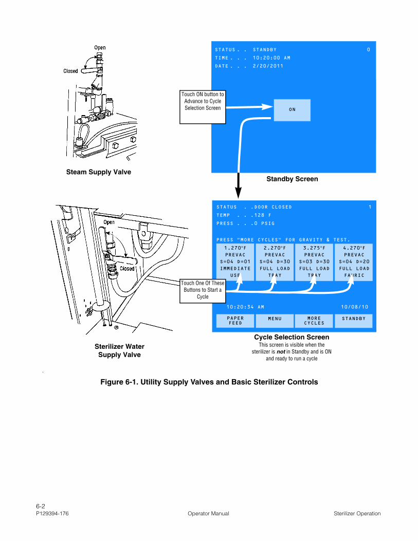
.
Figure 6-1. Utility Supply Valves and Basic Sterilizer Controls
Steam Supply Valve
Sterilizer Water Supply Valve
STATUS . . STANDBY 0
TIME . . . 10:20:00 AM
DATE . . . 2/20/2011
ON
Standby Screen
Cycle Selection ScreenThis screen is visible when the
sterilizer is not in Standby and is ON and ready to run a cycle
STATUS . .DOOR CLOSED 1
TEMP . . .128 F
PRESS . . .0 PSIG
PRESS "MORE CYCLES" FOR GRAVITY & TEST.
1.270°F 2.270°F 3.275°F 4.270°FPREVAC PREVAC PREVAC PREVAC
S=04 D=01 S=04 D=30 S=03 D=30 S=04 D=20
IMMEDIATE FULL LOAD FULL LOAD FULL LOAD
USE TRAY TRAY FABRIC
10:20:34 AM 10/08/10
STANDBYMENUPAPERFEED
MORECYCLES
Touch ON button to Advance to Cycle Selection Screen
Touch One Of These Buttons to Start a
Cycle
6-2P129394-176 Operator Manual Sterilizer Operation

6.2 Preparing Loadsfor Sterilization Cycles
Before sterilization, all materials must be thoroughly cleaned.
The AMSCO® C Series Small Steam Sterilizer chamber holdscommonly used wrapped or unwrapped instruments and equipment.
1. Wrappers may be made of 100% cotton, 140 thread count, two-ply fabric, and must be laundered; alternatively, use commercially available, non-woven disposable wrappers.
2. Limit the weight of each pack to approximately 3.3 lb (1.5 kg), and density to 11.3 lb/ft3 (181 kg/m3). This ensures complete steam penetration, and minimizes moisture retention.
3. Limit the weight of wrapped instrument sets to 25 lb (11 kg) to minimize moisture retention.
6.3 Guidelines forPlacement of
Various Loads
Refer to AAMI ST-79 for load placement guidelines.
1. Open the sterilizer chamber door.
NOTE: If a cycle has been run, sterilizer and shelves or loadingcar may be hot.
NOTE: Wear clean gloves and use clean towels as “pot holders”when carefully placing the load/tray(s) on the chamber shelves orloading car.
2. Place all packs on edge, and arrange load to allow for maximum steam exposure so there is minimal resistance for steam passage through the load.
3. Place utensils and treatment trays on their edges so they will be sterilized and properly dried.
4. Place instrument sets in trays that have a perforated or mesh bottom. Place flat for sterilization.
In mixed loads of fabrics and hard goods, place the hard goods on lower shelf. This reduces wetting of fabric packs from condensate dripping from a hard goods load.
DO NOT OVERLOAD STERILIZER. Allow for steam penetration between packs. Avoid contact of load components with the wall of the chamber.
5. After placing load in chamber, close the chamber door. The sterilizer is now ready to run a cycle. Proceed to appropriate cycle description in this section.
Materials capable of holding water, such as solid-bottomed pans, basins and trays, should be positioned so they are oriented in the same direction and so condensate can be eliminated.
Important: Refer to SECTION 4, TECHNIQUES OF STERILIZATION, foradditional information regarding pack preparation, loading andplacement.
WARNING – BURN HAZARD: Sterilizer, rack/shelves, and loading car will be hot after cycle is run. Always wear protective gloves and apron when removing a processed load. Protective gloves and apron must be worn when reloading sterilizer following the previous operation.
�
WARNING – PERSONAL INJURY HAZARD: When closing the chamber door, keep hands and arms out of the door opening and make sure opening is clear of any obstructions.
�
6-3Sterilizer Operation Operator Manual P129394-176

6.4 Unloading theSterilizer
At the end of a cycle, when end-of-cycle tone sounds and displayshows the complete display (see below), open the chamber door.
NOTE: Wear clean gloves and use clean towels as “pot holders”when carefully removing load/tray(s) from the sterilizer shelves orloading car.
NOTE: Never place a sterilized tray on a solid shelf or cold surface.Once the tray has cooled, it can be placed on a wire shelf.
1. Remove the load from chamber shelf (shelves). Avoid unnecessary handling.
2. Visually check outside wrapper for dryness. If there are water droplets or visible moisture on the exterior of the package, or on the tape used to secure it, the pack or instrument tray is considered unacceptable.
3. To prevent condensation, transfer the load to a surface which is well-padded with fabric. Do not place load on a cold surface. Be sure that no air conditioning or cold air vents are in close proximity.
4. Remove packs or instrument trays from the padded surface when they have reached ambient (room) temperature. Depending on the items and environment of the area, this may take a minimum of one hour.
Important: After removing load(s) from the chamber, close thechamber door and keep the chamber door closed to minimize utilityconsumption.
WARNING – BURN HAZARD:
• Sterilizer and shelves will be hot after cycle is run. Always wear protective gloves and apron when removing a processed load.
• Steam may be released from the chamber when door is opened. Step back from the sterilizer each time the door is opened to minimize contact with steam vapor.
WARNING – SLIPPING HAZARD: To prevent falls, keep floors dry by immediately wiping up any spilled liquids or condensation in sterilizer loading or unloading area.
�
�
STATUS . .COMPLETE 00:00:00 5
TEMP . . .127 F
PRESS . . .0 psig
3.TRAY, PREVAC, 270F, 4, 30
OPEN DOOR & UNLOAD CHAMBER
PAPER STATUSFEED PRINT ABORT
6-4P129394-176 Operator Manual Sterilizer Operation
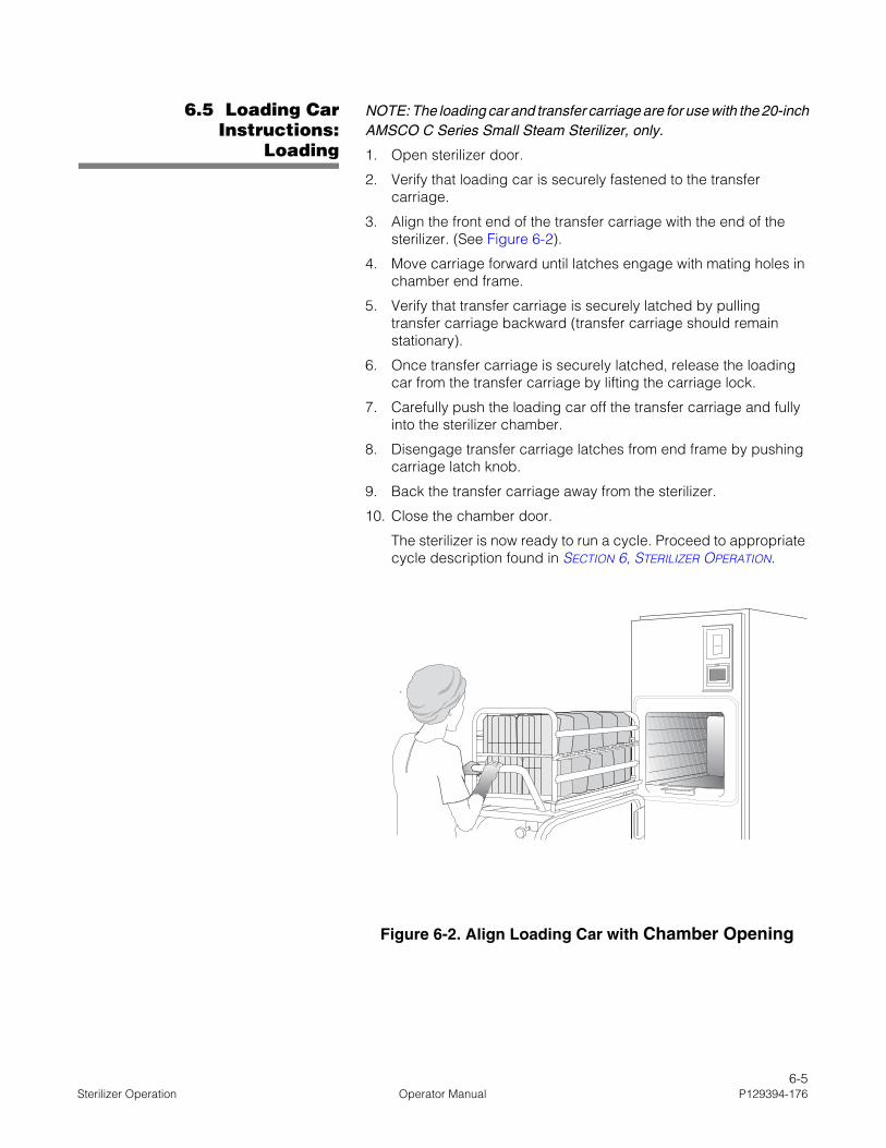
6.5 Loading CarInstructions:
Loading
NOTE: The loading car and transfer carriage are for use with the 20-inchAMSCO C Series Small Steam Sterilizer, only.
1. Open sterilizer door.
2. Verify that loading car is securely fastened to the transfer carriage.
3. Align the front end of the transfer carriage with the end of the sterilizer. (See Figure 6-2).
4. Move carriage forward until latches engage with mating holes in chamber end frame.
5. Verify that transfer carriage is securely latched by pulling transfer carriage backward (transfer carriage should remain stationary).
6. Once transfer carriage is securely latched, release the loading car from the transfer carriage by lifting the carriage lock.
7. Carefully push the loading car off the transfer carriage and fully into the sterilizer chamber.
8. Disengage transfer carriage latches from end frame by pushing carriage latch knob.
9. Back the transfer carriage away from the sterilizer.
10. Close the chamber door.
The sterilizer is now ready to run a cycle. Proceed to appropriate cycle description found in SECTION 6, STERILIZER OPERATION.
Figure 6-2. Align Loading Car with Chamber Opening
6-5Sterilizer Operation Operator Manual P129394-176

6.6 Loading CarInstructions:
Unloading
NOTE: The loading car and transfer carriage are for use with the 20-inchAMSCO C Series Small Steam Sterilizer, only.
1. Open sterilizer door.
2. Move transfer carriage forward until latches engage with track inside chamber.
3. Verify that transfer carriage latched to track inside chamber by pulling transfer carriage backward (transfer carriage should remain stationary).
4. Once transfer carriage is latched to track inside chamber, grasp the loading car and carefully pull loading car from chamber onto transfer carriage until transfer carriage latch engages to loading car.
5. Disengage transfer carriage latches from track inside chamber by pushing carriage latch knob.
6. Close the sterilizer door.
7. Transfer load from sterilizer area.
6.7 Loading/UnloadingSterilizer:
Rack and Shelves
If sterilizer is equipped with the rack and shelves option, refer toinstructions below and Figure 6-3.
1. Open chamber door.
2. Transfer load to shelves in chamber. Shelves slide out halfway to facilitate loading.
3. After loading the shelves, slide them to closed position to verify shelf does not interfere with door operation (both doors if double-door sterilizer).
4. Close chamber door(s).
5. The sterilizer is now ready to run a cycle. Refer to appropriate cycle description in SECTION 6, STERILIZER OPERATION (later in this section of the manual).
WARNING – BURN HAZARD: Sterilizer, rack/shelves and loading car will be hot after cycle is run. Always wear protective gloves and apron when removing a processed load. Protective gloves and apron must be worn when reloading sterilizer following the previous operation.
�
WARNING – BURN HAZARD: Steam may be released from the chamber when door is opened. Step back from the sterilizer each time the door is opened to minimize contact with steam vapor.
WARNING – PERSONAL INJURY HAZARD: When closing the chamber door, keep hands and arms out of the door opening and make sure opening is clear of obstructions.
�
�
WARNING – BURN HAZARD: Sterilizer, rack/shelves and loading car will be hot after cycle is run. Always wear protective gloves and apron when removing a processed load. Protective gloves and apron must be worn when reloading sterilizer following the previous operation.
�
6-6P129394-176 Operator Manual Sterilizer Operation

6. Following successful completion of the sterilization cycle, unload the sterilizer as follows:
a. Open chamber door.
b. Remove load from chamber.
c. Slide shelves into chamber, verifying that position does not interfere with door operation.
d. Close chamber door.
e. Transfer load to destination.
Figure 6-3. Sterilizer Chamber Equipped with Rack and Shelves
6.8 PrevacuumSterilizer Cycles
AMSCO C Series Small Steam Prevacuum Sterilizers are shippedwith the factory-set cycles. Cycle descriptions are given in SECTION
6.9, through SECTION 6.14. Refer to Table 1 (page ii) for factory set,qualified cycle settings.
Important: Applicable cycles have been validated to satisfy therequirements outlined in Table 4-1 and Table 4-2. If cycleparameters (sterilize time, dry time, temperature) other than thoselisted are required, it is the responsibility of the healthcare facility toconsult and follow the device manufacturer’s written instructions.
NOTE: Contact STERIS Corporation for information on a wide rangeof education/training programs designed to meet the educationalneeds of healthcare industries.
WARNING – BURN HAZARD: Steam may be released from the chamber when door is opened. Step back from the sterilizer each time the door is opened to minimize contact with steam vapor.
WARNING – SLIPPING HAZARD: To prevent falls keep floors dry by immediately wiping up any spilled liquids or condensation in sterilizer loading or unloading area.
�
�
6-7Sterilizer Operation Operator Manual P129394-176

Table 6-1. Factory-Set Prevacuum Cycles and Cycle ValuesThe AMSCO C Series Prevacuum Small Steam Sterilizer is equipped with the following factory programmed
prevacuum sterilization cycles and cycle values.
Cycles Sterilize Temp.
Sterilize Time
Dry Time Recommended Load
Validation Standard
Prevac Cycle270°F
(132°C)4
Minutes20
Minutes*
* Dry time can be reduced to 5 minutes for a single fabric pack.
Fabric Packs ST-8:2008
Prevac Cycle270°F
(132°C)4
Minutes30
Minutes
Double-wrapped instrument trays, porous and non-porous loads; maximum weight per tray: 25 lb (11.3 kg)
ST-8:2008
Prevac Cycle275°F
(135°C)3
Minutes30
Minutes
Double-wrapped instrument trays, porous and non-porous loads; maximum weight per tray: 25 lb (11.3 kg)
ST-8:2008
Immediate UsePrevac Cycle
270°F (132°C)
4 Minutes
1 Minute
Unwrapped instrument tray containing a single instrument, or multiple unwrapped instrument trays, porous and non-porous loads; maximum weight per tray: 25 lb (11.3 kg)
ST-8:2008
Figure 6-4. Prevac Cycle In-Cycle Screens
Cycle Selection ScreenCycle Selection Screen
Purge Phase Sterilize Phase Exhaust Phase
Press for More Cycles
NOTE: Countdown time on display is estimated; timer self-corrects estimated time at beginning of each phase.
6-8P129394-176 Operator Manual Sterilizer Operation

6.9 Prevac Cycles Prevac cycles, 270°F (132°C), are used for sterilizing double-wrapped instrument trays or fabric packs. Prevac cycles, 275°F (135°C), are used for sterilizing double-wrapped instrument trays only. Immediate use cycles must not be used with wrapped loads or fabrics.
1. Before running this cycle refer to SECTION 6.1, BEFORE OPERATING THE STERILIZER, ON PAGE 6-1.
2. See instructions for using the loading car/transfer carriage or rack and shelves, earlier in this section, for procedures to load the sterilizer.
• For 270°F (132°C) Cycle, press 270 PREVAC button to start the prevacuum cycle. Refer to Table 6-1 for descriptions of cycle use and loading recommendations.
• For 275°F (135°C) Cycle press 275 PREVAC touch-screen pad to start the 275°F (135°C) Prevacuum cycle. Refer to Table 6-1 for descriptions of cycle use and loading recommendations.
NOTE: If the wrong cycle has been selected, see SECTION 6.15,ABORTING CYCLES, ON PAGE 6-30.
3. Sterilizer automatically progresses through cycle, as follows:
NOTE: The control display indicates cycle progress in two ways:
a. Large numerals in the screen’s center display estimated remaining cycle time,
b. Change of phase name in the top status line of the screen.
ACTIVATE SEAL – Steam enters the door seal, pressing it against inside surface of the door.
PURGE – Chamber is purged with steam. Start of Condition is printed.
VACUUM/PRESSURE PULSES – Differing by temperature rating for the cycle:
• 270°F (132°C) #1 - #4 – Four vacuum pulses.
• 275°F (135°C) #1 – #3 – Three vacuum pulses.
CHARGE – Chamber is charged with steam. Start of steam charge is printed.
STERILIZE – Start of sterilize exposure is printed when the chamber reaches sterilization temperature. Chamber temperature is printed every minute.
FAST EXHAUST – Start of exhaust is printed and chamber is exhausted to 4 psig (0.28 bar).
DRY – Start of dry is printed and display counts down dry time remaining.
AIR BREAK – Chamber is returned to atmospheric pressure.
RETRACT SEAL – A vacuum is drawn on the seal, retracting it from inner surface of door.
COMPLETE – Complete tone sounds. Cycle summary and end of cycle messages are printed.
4. Unload sterilizer (see instructions for using the loading car/transfer carriage or rack and shelves, SECTION 6.4, UNLOADING
THE STERILIZER, ON PAGE 6-4 for procedures to remove load).
WARNING – BURN HAZARD:
• Sterilizer, rack/shelves and loading equipment will be hot after cycle is run. Always wear protective gloves and apron when removing a processed load. Protective gloves and apron must be worn when reloading sterilizer following the previous operation.
• Steam may be released from the chamber when door is opened. Step back from the sterilizer each time the door is opened to minimize contact with steam vapor.
WARNING – SLIPPING HAZARD: To reduce slippery conditions, keep floors dry by immediately wiping up any spilled liquids or condensation in sterilizer loading or unloading area.
WARNING – PERSONAL INJURY and/or EQUIPMENT DAMAGE HAZARD: When closing the chamber door, keep hands and arms out of the door opening and make sure opening is clear of obstructions.
�
�
�
6-9Sterilizer Operation Operator Manual P129394-176

Figure 6-5. Typical Prevacuum Cycle Printouts
270°F (132°C) Prevac, Full Load, Fabric Packs
Cycle Printout
270°F (132°C) Prevac,Immediate UseCycle Printout
6-10P129394-176 Operator Manual Sterilizer Operation

Table 6-2. Factory-Set Gravity Cycles and Cycle ValuesThe AMSCO C Series Prevacuum Sterilizer is equipped with the following factory programmed gravity sterilization
cycles and cycle values.
Cycles Sterilize
Temp. Sterilize
TimeDry
Time Recommended LoadValidation Standard
Immediate Use Gravity Cycle
270°F (132°C)
3 Minutes
1 MinuteUnwrapped instrument tray containing a single instrument; or multiple unwrapped instrument trays, non-porous load; maximum weight per tray: 25 lb (11.3 kg).
ST-8:2008
Immediate Use Gravity Cycle
270°F (132°C)
10 Minutes
1 Minute ST-8:2008
Figure 6-6. Gravity Cycle In-Cycle Screens
Cycle Selection Screen
Purge Phase Sterilize Phase Exhaust Phase
NOTE: Countdown time on display is estimated; timer self-corrects estimated time at beginning of each phase.
Press for More Cycles
Confirmation Screen for Less-Than-25-Minute Gravity Cycle
Confirmation Screen for Less-Than-15-Minute Gravity Cycle
6-12P129394-176 Operator Manual Sterilizer Operation
6.10 Gravity Cycles The Gravity cycle is used for sterilizing one or more unwrapped instrument trays containing non-porous items.
1. Refer to SECTION 6.1, BEFORE OPERATING THE STERILIZER, ON PAGE 6-1 before running this cycle.
2. See instructions for using the loading car/transfer carriage or rack and shelves, earlier in this section, for procedures to load the sterilizer.
3. To start the Gravity cycle, press the appropriate GRAVITY touch-screen pad. Refer to Table 6-2 for descriptions of cycle use.
4. Confirmation screen #47 or #51 appears on the control (see facing page). Verify correct load is in the chamber to match sterilize exposure time for selected cycle and press YES or NO to continue.
NOTE: If the wrong cycle has been selected, see SECTION 6.15,ABORTING CYCLES, ON PAGE 6-30.
5. Sterilizer automatically progresses through cycle, as follows:
NOTE: The control display indicates cycle progress in two ways:
a. Large numerals in the screen’s center display estimated remaining cycle time,
b. Change of phase name in the top status line of the screen.
ACTIVATE SEAL – Steam enters the door seal, pressing it against inside surface of the door.
PURGE – Chamber is purged with steam. Start of condition is printed.
CHARGE – Chamber is charged with steam. Start of steam charge is printed.
STERILIZE – Start of sterilize exposure is printed when the chamber reaches sterilization temperature. Chamber temperature is printed every minute.
FAST EXHAUST – Start of exhaust is printed and chamber is exhausted to 4 psig.
DRY – Start of dry is printed and display counts down dry time remaining.
AIR BREAK – Chamber is returned to atmospheric pressure.
RETRACT SEAL – A vacuum is drawn on the seal, retracting it from inner surface of door.
COMPLETE – Complete tone sounds. Cycle summary and end of cycle messages are printed.
6. Unload sterilizer (see instructions for using the loading car/transfer carriage or rack and shelves, earlier in this section for procedures to remove load).
WARNING – BURN HAZARD:
• Sterilizer, rack/shelves and loading equipment will be hot after cycle is run. Always wear protective gloves and apron when removing a processed load. Protective gloves and apron must be worn when reloading sterilizer following the previous operation.
• Steam may be released from the chamber when door is opened. Step back from the sterilizer each time the door is opened to minimize contact with steam vapor.
WARNING – SLIPPING HAZARD: To reduce slippery conditions, keep floors dry by immediately wiping up any spilled liquids or condensation in sterilizer loading or unloading area.
WARNING – PERSONAL INJURY HAZARD: When closing the chamber door, keep hands and arms out of the door opening and make sure opening is clear of obstructions.
�
�
�
6-13Sterilizer Operation Operator Manual P129394-176

Figure 6-7. Typical Gravity Cycle Printout
270°F (132°C) Gravity,Immediate UseCycle Printout
6-14P129394-176 Operator Manual Sterilizer Operation
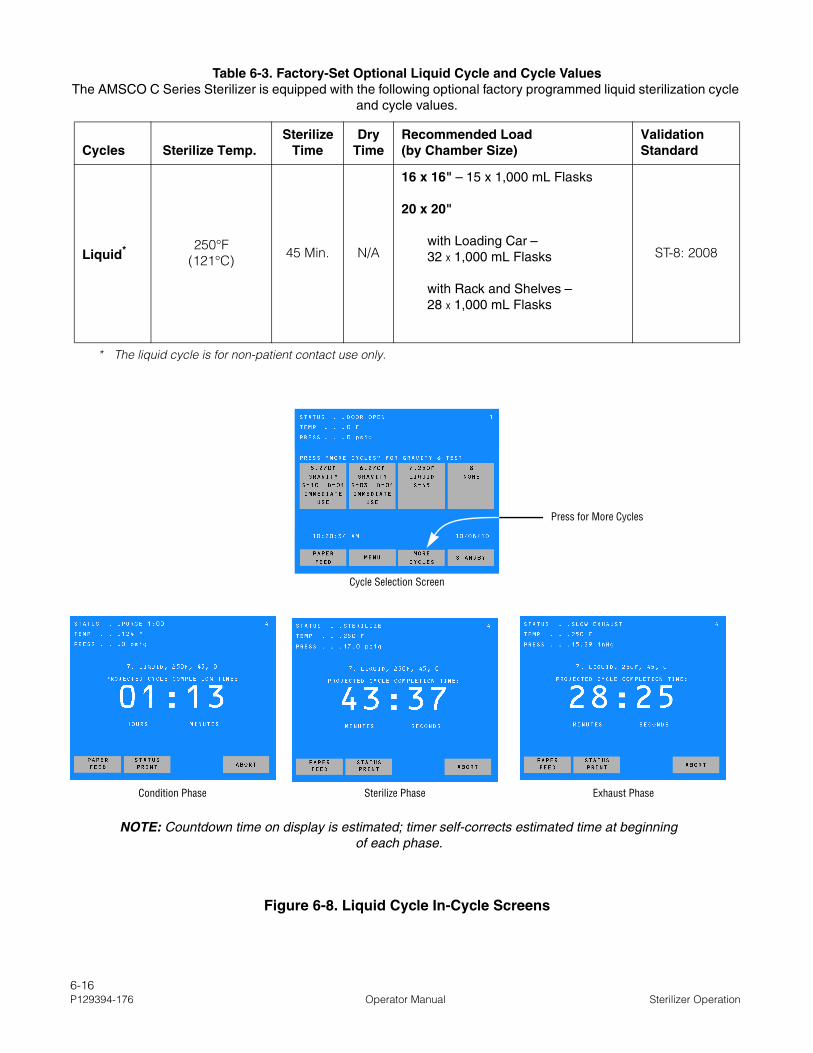
Table 6-3. Factory-Set Optional Liquid Cycle and Cycle ValuesThe AMSCO C Series Sterilizer is equipped with the following optional factory programmed liquid sterilization cycle
and cycle values.
Cycles Sterilize Temp. Sterilize
TimeDry
TimeRecommended Load(by Chamber Size)
Validation Standard
Liquid* 250°F(121°C)
45 Min. N/A
16 x 16" – 15 x 1,000 mL Flasks
20 x 20"
with Loading Car –32 x 1,000 mL Flasks
with Rack and Shelves –28 x 1,000 mL Flasks
ST-8: 2008
* The liquid cycle is for non-patient contact use only.
Figure 6-8. Liquid Cycle In-Cycle Screens
Cycle Selection Screen
Condition Phase Sterilize Phase Exhaust Phase
NOTE: Countdown time on display is estimated; timer self-corrects estimated time at beginning of each phase.
Press for More Cycles
6-16P129394-176 Operator Manual Sterilizer Operation
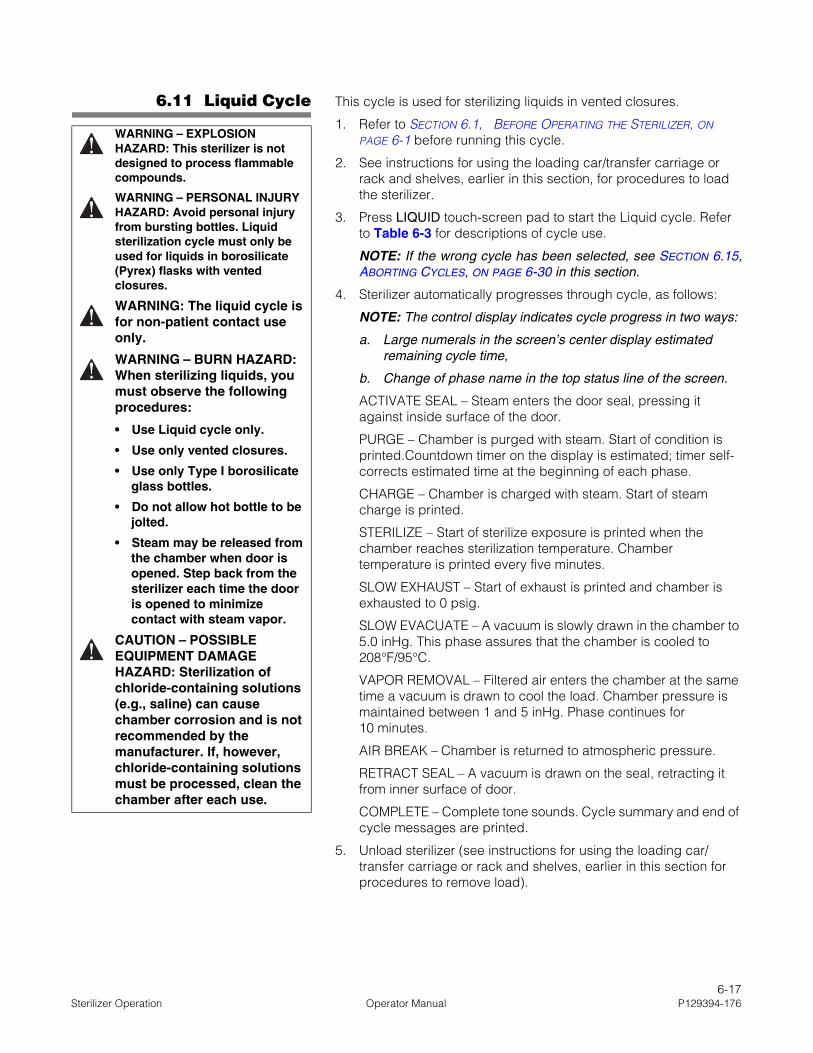
6.11 Liquid Cycle This cycle is used for sterilizing liquids in vented closures.
1. Refer to SECTION 6.1, BEFORE OPERATING THE STERILIZER, ON PAGE 6-1 before running this cycle.
2. See instructions for using the loading car/transfer carriage or rack and shelves, earlier in this section, for procedures to load the sterilizer.
3. Press LIQUID touch-screen pad to start the Liquid cycle. Refer to Table 6-3 for descriptions of cycle use.
NOTE: If the wrong cycle has been selected, see SECTION 6.15,ABORTING CYCLES, ON PAGE 6-30 in this section.
4. Sterilizer automatically progresses through cycle, as follows:
NOTE: The control display indicates cycle progress in two ways:
a. Large numerals in the screen’s center display estimated remaining cycle time,
b. Change of phase name in the top status line of the screen.
ACTIVATE SEAL – Steam enters the door seal, pressing it against inside surface of the door.
PURGE – Chamber is purged with steam. Start of condition is printed.Countdown timer on the display is estimated; timer self-corrects estimated time at the beginning of each phase.
CHARGE – Chamber is charged with steam. Start of steam charge is printed.
STERILIZE – Start of sterilize exposure is printed when the chamber reaches sterilization temperature. Chamber temperature is printed every five minutes.
SLOW EXHAUST – Start of exhaust is printed and chamber is exhausted to 0 psig.
SLOW EVACUATE – A vacuum is slowly drawn in the chamber to 5.0 inHg. This phase assures that the chamber is cooled to 208°F/95°C.
VAPOR REMOVAL – Filtered air enters the chamber at the same time a vacuum is drawn to cool the load. Chamber pressure is maintained between 1 and 5 inHg. Phase continues for 10 minutes.
AIR BREAK – Chamber is returned to atmospheric pressure.
RETRACT SEAL – A vacuum is drawn on the seal, retracting it from inner surface of door.
COMPLETE – Complete tone sounds. Cycle summary and end of cycle messages are printed.
5. Unload sterilizer (see instructions for using the loading car/transfer carriage or rack and shelves, earlier in this section for procedures to remove load).
WARNING – EXPLOSION HAZARD: This sterilizer is not designed to process flammable compounds.
WARNING – PERSONAL INJURY HAZARD: Avoid personal injury from bursting bottles. Liquid sterilization cycle must only be used for liquids in borosilicate (Pyrex) flasks with vented closures.
WARNING: The liquid cycle is for non-patient contact use only.
WARNING – BURN HAZARD: When sterilizing liquids, you must observe the following procedures:
• Use Liquid cycle only.
• Use only vented closures.
• Use only Type I borosilicate glass bottles.
• Do not allow hot bottle to be jolted.
• Steam may be released from the chamber when door is opened. Step back from the sterilizer each time the door is opened to minimize contact with steam vapor.
CAUTION – POSSIBLE EQUIPMENT DAMAGE HAZARD: Sterilization of chloride-containing solutions (e.g., saline) can cause chamber corrosion and is not recommended by the manufacturer. If, however, chloride-containing solutions must be processed, clean the chamber after each use.
�
�
�
�
�
6-17Sterilizer Operation Operator Manual P129394-176
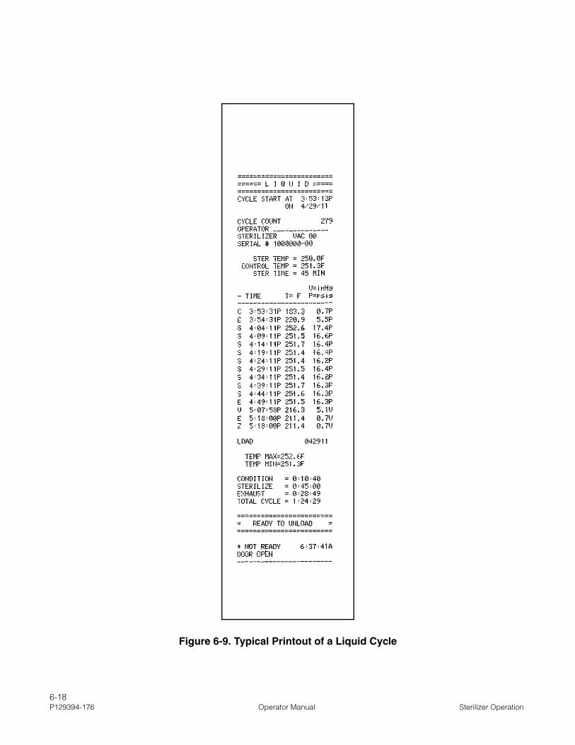
Figure 6-9. Typical Printout of a Liquid Cycle
6-18P129394-176 Operator Manual Sterilizer Operation

6.12 SFPP SterilizerCycles
AMSCO C Series SFPP Steam Sterilizers are shipped with factory-setcycles. The cycle sequence for these cycles is given in SECTION 6.13(prevac and gravity cycles are described in SECTION 6.9, SECTION
6.10 and SECTION 6.11). Refer below, and to Table 2 (page iii) forfactory-set, qualified cycle settings.
Important: Applicable cycles have been validated to satisfy therequirements outlined in Table 4-1 and Table 4-2. If cycleparameters (sterilize time, dry time, temperature) other than thoselisted are required, it is the responsibility of the healthcare facility toconsult and follow the device manufacturer’s written instructions.
NOTE: Contact your customer service representative for informationon a wide range of education/training programs designed to meet theeducational needs of healthcare industries.
6-19Sterilizer Operation Operator Manual P129394-176

Table 6-4. Factory-Set SFPP Sterilizer Cycles and Cycle Values
Cycles Sterilize
Temp. Sterilize Time
Dry Time Recommended Load
Validation Standard
SFPP Cycle270°F
(132°C)4
Minutes30
Minutes
Double-wrapped instrument trays, porous and non-porous loads. Maximum weight per tray, 25 lb (11.3 kg)
ST-8:2008
SFPP Cycle270°F
(132°C)4
Minutes20
Minutes* Fabric Packs ST-8:2008
SFPP Cycle275°F
(135°C)3
Minutes30
Minutes
Double-wrapped instrument trays, porous and non-porous loads. Maximum weight per tray, 25 lb (11.3 kg)
ST-8:2008
* Dry time can be reduced to 5 minutes for a single fabric pack.
Figure 6-10. SFPP Cycle In-Cycle Screens
Cycle Selection Screen
Condition Phase Sterilize Phase Exhaust Phase
NOTE: Countdown time on display is estimated; timer self-corrects estimated time at beginning of each phase.
Press for More Cycles
6-20P129394-176 Operator Manual Sterilizer Operation

6.13 SFPP Cycles SFPP cycles are designed for sterilizing both fabric packs and instrument trays. The cycle conditions loads at above-atmospheric pressure.
NOTE: NOTE: Make sure items are clean and free of soil.
1. Refer to SECTION 6.1, BEFORE OPERATING THE STERILIZER, ON PAGE 6-1 before running this cycle.
2. See instructions for using the loading car/transfer carriage or rack and shelves, earlier in this section, for procedures to load the sterilizer.
3. Press the SFPP touch-screen pad to start the SFPP cycle. Refer to Table 6-4 for descriptions of cycle use.
NOTE: If the wrong cycle has been selected, see SECTION 6.15,ABORTING CYCLES, ON PAGE 6-30.
NOTE: The control display indicates cycle progress in two ways:
a. Large numerals in the screen’s center display estimated remaining cycle time,
b. Change of phase name in the top status line of the screen.
4. Sterilizer automatically progresses through cycle, as follows:
ACTIVATE SEAL – Steam enters the door seal, pressing it against inside surface of door.
PURGE – Chamber is purged with steam. Start of condition is printed.
STEAM FLUSH – (SFPP) PULSE #1 through PULSE #3 – Pressure point is printed and pressure pulse is repeated.
CHARGE – Chamber is charged with steam. Start of steam charge is printed.
STERILIZE – Start of sterilize exposure is printed when the chamber reaches sterilization temperature. Chamber temperature is printed every minute.
FAST EXHAUST – Start of exhaust is printed and chamber is exhausted to 4 psig.
DRY – Start of dry is printed and display counts down dry time remaining.
AIR BREAK – Chamber is returned to atmospheric pressure.
RETRACT SEAL – A vacuum is drawn on the seal, retracting it from inner surface of door.
COMPLETE – Complete tone sounds. Cycle summary and end of cycle messages are printed.
5. Unload sterilizer (see instructions for using the loading car/transfer carriage or rack and shelves, earlier in this section, for procedures to remove load).
WARNING – BURN HAZARD:
• Sterilizer, rack/shelves, and loading car will be hot after cycle is run. Always wear protective gloves and apron when removing a processed load. Protective gloves and apron must be worn when reloading sterilizer following the previous operation.
• Steam may be released from the chamber when door is opened. Step back from the sterilizer each time the door is opened to minimize contact with steam vapor.
WARNING – SLIPPING HAZARD: To reduce slippery conditions, keep floors dry by immediately wiping up any spilled liquids or condensation in sterilizer loading or unloading area.
WARNING – PERSONAL INJURY HAZARD: When closing the chamber door, keep hands and arms out of the door opening and make sure opening is clear of obstructions.
�
�
�
6-21Sterilizer Operation Operator Manual P129394-176

Figure 6-11. Typical Printouts – 270°F SFPP and 275° SFPP Cycles
270°F (132°C) SFPP,Full Load, Fabric Packs
Cycle Printout
275°F (135°C) SFPP,Full Load, Instruments Trays
Cycle Printout
6-22P129394-176 Operator Manual Sterilizer Operation

6.14 Test Cycles Test cycles are factory programmed on prevacuum sterilizers. These cycles are used to verify the sterilizer is functioning at optimum capability.
Table 6-5. Test Cycles
Test Cycles for All Units
Sterilize Temp. Sterilize Time
Dry Time Recommended Load
Validation Standard
Dart Warm-up* 270°F (132°C) 3 Minutes 1 Minute N/A N/A
Dart (Bowie-Dick) Test*
270°F (132°C) 3-1/2 Minutes 1
MinuteDart or Bowie-Dick Test Pack ST-8: 2008
Leak Test* N/A N/A N/A N/A ST-8: 2008
* Not adjustable.
Figure 6-12. Test Cycles Start-Cycle Screens
Cycle Selection Screen Test Cycle Screen
Press the “More Cycles” button to advanceto Test Cycles screen.
Press the desired test cycle button (Warm-Up Cycle, Dart Test or Leak Test) to run the required cycle.
ACCESSING TEST CYCLES
STATUS . . DOOR OPEN 1
TEMP . . . 0 F
PRESS . . 0 psig
PRESS "MORE CYCLES" FOR GRAVITY & TEST
1.SHORT 2.FABRIC 3.TRAY 4.TRAY
PREVAC PREVAC PREVAC PREVAC
270F 270F 270F 275F
S= 4M S= 4M S= 4M S= 3M
D= 1M D=20M D=30M D=30M
10:20:34 AM 10/08/10
PAPER MORE
FEED CYCLESSTANDBYMENU
STATUS . . DOOR OPEN 9
TEMP . . . 0 F
PRESS . . 0 psig
BOWIE- BOWIE- LEAK
DICK DICK TEST
WARM-UP TEST
10:20:34 AM 10/08/10
PAPER MORE
FEED CYCLESSTANDBYMENU
6-24P129394-176 Operator Manual Sterilizer Operation

6.14.1 Dart (Bowie-Dick) Test This cycle is used to conduct a Dart (Bowie-Dick) test on sterilizersthat use prevacuum cycles. This test is only applicable to sterilizersthat use prevacuum cycles. For SFPP sterilizers, if the SFPP cycle isused exclusively, there is no need to run a daily Dart (Bowie-Dick)test. If prevacuum cycles will also be run on the same sterilizer, thena daily Dart (Bowie-Dick) test must be run.
The Dart (Bowie-Dick) test is designed to document the removal of residual air from a sample challenge load (see Section 4.2.2, Testing for Prevacuum Efficiency, on page 4-2). Refer to SECTION 4, TECHNIQUES OF STERILIZATION, when constructing the Bowie-Dick test pack.
ANSI/AAMI ST-79 requires a Dart test cycle be run as the first cycle each day the sterilizer is in use. The chamber must be at operating temperature when the Dart test cycle is performed. The Warm-up cycle should be completed prior to performing the Dart test cycle.
NOTE: Always run this test cycle with either racks installed, or with anempty cart in the chamber.
1. Refer to SECTION 6.1, BEFORE OPERATING THE STERILIZER, ON PAGE 6-1, and to Section 4, Techniques of Sterilization, to prepare the unit for running this cycle.
2. Press the MORE CYCLES button to access the test cycle screen.
3. A Dart test should only be run in a machine that is at operating temperature (that is, has run one or more cycles). If the sterilizer has not run any cycles prior to the Dart (Bowie-Dick) test, run the Warm-up cycle as follows. If the chamber has already been warmed by previous cycle operation, proceed to Step 4.
a. The operator is prompted to close the chamber door, if it is open. Once closed, the door seals automatically.
b. During “warm up,” the sterilizer automatically runs a cycle with 3-minute sterilize and 1-minute dry values.
c. Once the Warm-up cycle is complete, the display returns to Test Cycles screen.
4. Open the chamber door (if it is not already open). Load the Dart (Bowie-Dick) test pack and close the door.
NOTE: For most accurate results, test pack should be locatedlow in the chamber, over the drain.
5. Start the Dart test cycle. The cycle runs automatically, as follows:
ACTIVATE SEAL – Steam enters the door seal, pressing seal against inside surface of door.
VACUUM/PRESSURE PULSES – #1 - #4 – Vacuum pulses (drawing from 2 - 24 inHg) are followed by pressure pulses (0.2 - 15 psig).
CHARGE – Chamber is charged with steam. Start of steam charge is printed.
WARNING – BURN HAZARD:
• Sterilizer, rack/shelves and loading equipment will be hot after cycle is run. Always wear protective gloves and apron when removing a processed load. Protective gloves and apron must be worn when reloading sterilizer following the previous operation.
• Steam may be released from the chamber when door is opened. Step back from the sterilizer each time the door is opened to minimize contact with steam vapor.
WARNING – PERSONAL INJURY and/or EQUIPMENT DAMAGE HAZARD: When closing the chamber door, keep hands and arms out of the door opening and make sure opening is clear of obstructions.
�
�
6-25Sterilizer Operation Operator Manual P129394-176

STERILIZE – Start of sterilize exposure is printed when the chamber reaches set temperature. Chamber temperature is printed every minute. Chamber is controlled at set point plus overdrive.
FAST EXHAUST – Start of exhaust is printed and chamber is exhausted to 4 psig (0.28 bar).
DRY – Start of dry is printed and display counts down dry time remaining.
AIR BREAK – Chamber is returned to atmospheric pressure.
RETRACT SEAL – A vacuum is drawn on the seal, retracting it from inner surface of door.
COMPLETE – Complete tone sounds. Cycle summary and end of cycle messages are printed.
6. Once the cycle is complete:
a. Open the chamber door.
b. Unload the Dart (Bowie-Dick) test pack.
c. Forward the exposed Dart (Bowie-Dick) indicator to the appropriate personnel for examination.
Important: Any indication of a malfunction must be reported to thesupervisor. Sterilizer must not be used again until approved bysupervisor. The cause of the malfunction must be determined andresolved prior to operating the sterilizer.
WARNING – BURN HAZARD:
• Sterilizer, rack/shelves and loading equipment will be hot after cycle is run. Always wear protective gloves and apron when removing a processed load. Protective gloves and apron must be worn when reloading sterilizer following the previous operation.
• Steam may be released from the chamber when door is opened. Step back from the sterilizer each time the door is opened to minimize contact with steam vapor.
�
6-26P129394-176 Operator Manual Sterilizer Operation
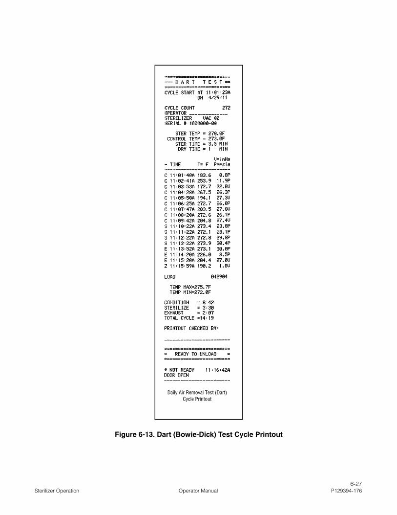
Figure 6-13. Dart (Bowie-Dick) Test Cycle Printout
Daily Air Removal Test (Dart) Cycle Printout
6-27Sterilizer Operation Operator Manual P129394-176
6.14.2 Vacuum Leak Test This cycle is used for testing vacuum integrity of the sterilizer andpiping.
A Vacuum Leak Test cycle should be run on the sterilizer at leastonce each week. It should be one of the first cycles run for the day,but not the first cycle. In this cycle, the sterilizer automatically checksfor vacuum leaks in the piping and door seal. If the sterilizer fails theleak test, it must be inspected by a qualified service technician. (Thistest is not a substitute for a Dart [Bowie-Dick] test.) The Leak Testcan also be used to confirm that the sterilizer piping is intact afterperforming repairs.
NOTE: The measured leak rate (millimeters of mercury [mm Hg] perminute) is calculated by the control over a timed 10-minute period andis included in the cycle printout. A leak rate of 1 mm Hg/minute or lessis considered acceptable.
1. Before running Leak Test cycle, refer to SECTION 6.1, BEFORE OPERATING THE STERILIZER, ON PAGE 6-1.
NOTE: The sterilizer should be warm before running this testcycle. If no other cycle has been run on the sterilizer before theLeak Test, run a Dart Warm Up cycle.
2. Press MORE CYCLES. The Leak Test cycle touch-screen pad appears on display.
3. To start the Leak Test, press the LEAK TEST touch-screen pad. Printer records cycle start. Cycle runs automatically as follows:
NOTE: Cycle requires 30-35 minutes to complete.
ACTIVATE SEAL – Steam enters the door seal, pressing seal against inside surface of door.
PURGE – Chamber is purged; printer records end of purge.
PULSE #1 (and PULSE #2) – Two vacuum and pressure pulses then occur and printer records each.
CHARGE – After the pressure pulses, temperature rises to 270°F (132°C), unit begins to draw a vacuum for 10 minutes. (Printer records temperature and pressure at beginning of 10-minute vacuum time.)
LEAK TEST/EVACUATING – Printer records temperature and vacuum at end of evacuation time.
LEAK TEST/STABILIZING – 2 -minute stabilization period begins after 10-minute evacuation is completed.
LEAK TEST – Ten minute Leak Test period begins after 2-minute stabilization is completed. Printer records calculated leak rate (mm Hg per minute) after 10-minute leak time.
AIR BREAK – Chamber is returned to atmospheric pressure, complete tone sounds and cycle summary and end of cycle messages are printed.
RETRACT SEAL – A vacuum is drawn on the seal, retracting it from inner surface of door.
COMPLETE – Complete tone sounds. Cycle summary and end of cycle messages are printed.
4. Once the sterilizer completes and passes the leak test, the unit can be used.
WARNING – BURN HAZARD:
• Sterilizer, rack/shelves and loading car will be hot after cycle is run. Always wear protective gloves and apron when removing a processed load. Protective gloves and apron must be worn when reloading sterilizer following the previous operation.
• Steam may be released from the chamber when door is opened. Step back from the sterilizer each time the door is opened to minimize contact with steam vapor.
WARNING – STERILITY ASSURANCE HAZARD: According to AAMI standards, a measured leak rate greater than 1 mm Hg/minute (1.3 mbar/min) indicates a problem with the sterilizer. Refer the situation to a qualified service technician before using the sterilizer further.
�
�
6-28P129394-176 Operator Manual Sterilizer Operation

Figure 6-14. Typical Printout of a Leak Test Cycle
Leak Test Cycle Printout
6-29Sterilizer Operation Operator Manual P129394-176
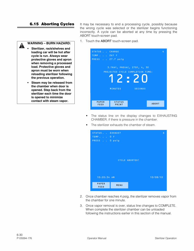
6.15 Aborting Cycles It may be necessary to end a processing cycle, possibly becausethe wrong cycle was selected or the sterilizer begins functioningincorrectly. A cycle can be aborted at any time by pressing theABORT touch-screen pad.
1. Touch the ABORT touch-screen pad.
• The status line on the display changes to EXHAUSTINGCHAMBER, if there is pressure in the chamber.
• The sterilizer exhausts the chamber of steam.
2. Once chamber reaches 4 psig, the sterilizer removes vapor from the chamber for one minute.
3. Once vapor removal is over, status line changes to COMPLETE. When complete the sterilizer chamber can be unloaded following the instructions earlier in this section of the manual.
WARNING – BURN HAZARD:
• Sterilizer, rack/shelves and loading car will be hot after cycle is run. Always wear protective gloves and apron when removing a processed load. Protective gloves and apron must be worn when reloading sterilizer following the previous operation.
• Steam may be released from the chamber when door is opened. Step back from the sterilizer each time the door is opened to minimize contact with steam vapor.
�STATUS . . CHARGE 4
TEMP . . . 261 F
PRESS . . 27.7 psig
3.TRAY, PREVAC, 270F, 4, 30
PROJECTED CYCLE COMPLETION TIME:
12:20MINUTES SECONDS
PAPER STATUSFEED PRINT ABORT
STATUS . . EXHAUST 6
TEMP . . . 0 F
PRESS . . 0 psig
CYCLE ABORTED!
10:20:34 AM 10/08/10
PAPER
FEEDMENU
6-30P129394-176 Operator Manual Sterilizer Operation

6.16 Cycle Graphs These cycle graphs provide a visual representation of AMSCO CSeries Small Steam Sterilizer cycles and their phases.
Figure 6-15. Cycle Graph – 270°F or 275°F Prevacuum and Dart (Bowie-Dick) Cycles
Figure 6-16. Cycle Graph – Gravity Cycle
Indicates Key Cycle Transition Points That Are Printed During Cycle
Pres
sure
Time
*Pulses
*NOTE: 270°F (132°C) prevac cycle runs four conditioning vacuum pulses. 275°F (135°C) prevac runs three conditioning vacuum pulses.
Purge ChargeFastExh Dry Ai
r Bre
ak
Retra
ct S
eals
Com
plet
e
ExhaustSterilizeConditioning
Act
ivat
eS
eal( s
)
Time
Indicates Key Cycle Transition Points That Are Printed During Cycle
Pres
sure
Purge ChargeFastExh Vac Dry Ai
r Bre
ak
Retr
act S
eals
Com
plet
e
Vacuum Dry phase only occurs when Dry Time
is set to 0.
ExhaustSterilizeConditioningAct
iva t
eS
eal(s
)
6-31Sterilizer Operation Operator Manual P129394-176

Figure 6-17. Cycle Graph – Leak Test
Figure 6-18. Cycle Graph – Steam Flush Pressure Pulse (SFPP) Cycles
Indicates Key Cycle Transition Points That Are Printed During Cycle
Time
Pres
sure
Pulse#1Purge Evacuate
Stabilizing Ai
r Bre
ak
Retra
ct S
eals
Com
plet
e
Leak TestingConditioning
Act
ivat
e S
eal(s
)
Pulse#2 Charge Leak
Test
Indicates Key Cycle Transition Points That Are Printed During Cycle
Time
Pres
sure
Conditioning
Air D
ispl
acem
ent
Purg
e
Char
ge
Activ
ate
Seal
(s) Sterilize Exhaust
Retra
ct S
eal(s
)
Com
plet
e
3 Pulses & Steam Flushes
Fast
Exh
aust
Air B
reak
DryExhaust Flush Pulse Exhaust Flush
6-32P129394-176 Operator Manual Sterilizer Operation
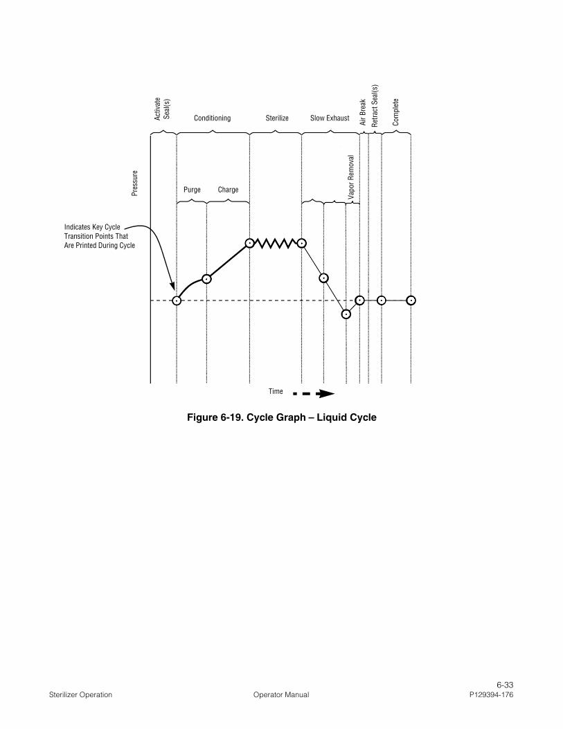
Figure 6-19. Cycle Graph – Liquid Cycle
Indicates Key Cycle Transition Points That Are Printed During Cycle
Conditioning
Purge Charge
Activ
ate
Seal
(s)
Sterilize Slow Exhaust
Retra
ct S
eal(s
)
Com
plet
e
Pres
sure
Vapo
r Rem
oval
Time
Air B
reak
6-33Sterilizer Operation Operator Manual P129394-176
7-1
AMSCO® C Series Small Steam Sterilizers are shipped with factory-set cycles, cycle values and control values programmed into thecontrol (see Table 1, Table 2 and Table 3; page ii, iii and iii). Presetvalues can be changed to tailor the sterilizer to the operatingenvironment in which it has been placed. To change these values,refer to Section 7.2, Change Cycle Values, on page 7-2.
NOTE: If a battery/memory failure should occur, operator-set cyclesand values would be lost.
Important: Applicable cycles have been validated to satisfy therequirements outlined in Table 4-1 and Table 4-2. If cycleparameters (sterilize time, dry time, temperature) other than thoselisted are required, it is the responsibility of the healthcare facility toconsult and follow the device manufacturer’s written instructions.
NOTE: Although AMSCO C Series Small Steam Sterilizers arefactory-set to operate using Fahrenheit temperature units, thesterilizer can be reprogrammed to display and print using Celsiustemperature units.
7.1 Change Values The Change Values procedure described in the following pages canbe used to adjust cycle values within a limited range and to makeselections affecting operation of the unit. Refer to Table 1, Table 2and Table 3 for tested cycle values.
NOTE: Default cycle values are shown on Table 1, Table 2 andTable 3 (page ii and iii).
The Change Values Procedure can be used to adjust the followingvalues:
• Name: The user can select between 3 to 4 factory-programmed names (depending on sterilizer configuration), and can create up to two user-defined cycle names.
• Sterilization Exposure Temperature: Exposure temperatures can be adjusted, but within limits. Refer to Table 7-1 for details.
• Sterilization Exposure Time: (Important: This value is limited to a minimum value, refer to Section 7.4, Change Time and Date, on page 7-8). Refer to Table 7-1 for range limits.
• Dry Time: Refer to Table 7-1 for range limits.
NOTE: Change Values can also be used to make adjustments to theChange Machine Setup values shown on Table 7-2.
The Change Values touch screens are accessed by pressing theChange Values touchpad (see Screen #2). All Change Valuesoptions can be secured (or locked out) using a supervisor’s accesscode. It is recommended that supervisor’s Access Code be used toprevent unauthorized personnel from changing cycle and systemsetup parameters.
NOTE: Although AMSCO C Series Small Steam Sterilizers arefactory-set to operate using Fahrenheit temperature units, thesterilizer can be reprogrammed to display and print using Celsiustemperature units.
IMPORTANT
Applicable cycles have been validated to satisfy the requirements outlined in Table 4-1 and Table 4-2. If cycle parameters (sterilize time, dry time, temperature) other than those listed are required, it is the responsibility of the healthcare facility to consult and follow the device manufacturer’s written instructions.
CYCLE AND CONTROL VALUE PROGRAMMING
Cycle and Control Value Programming Operator Manual P
7
129394-176
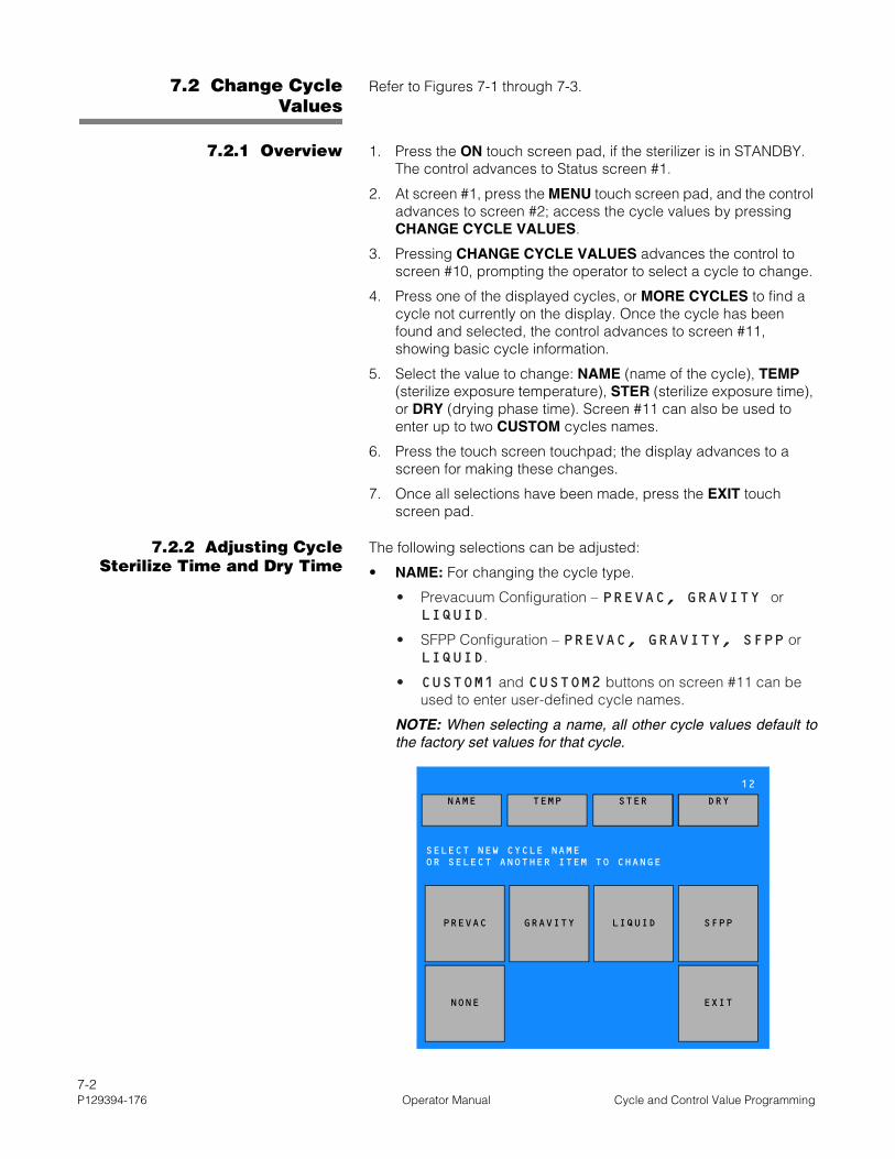
7.2 Change CycleValues
Refer to Figures 7-1 through 7-3.
7.2.1 Overview 1. Press the ON touch screen pad, if the sterilizer is in STANDBY. The control advances to Status screen #1.
2. At screen #1, press the MENU touch screen pad, and the control advances to screen #2; access the cycle values by pressing CHANGE CYCLE VALUES.
3. Pressing CHANGE CYCLE VALUES advances the control to screen #10, prompting the operator to select a cycle to change.
4. Press one of the displayed cycles, or MORE CYCLES to find a cycle not currently on the display. Once the cycle has been found and selected, the control advances to screen #11, showing basic cycle information.
5. Select the value to change: NAME (name of the cycle), TEMP (sterilize exposure temperature), STER (sterilize exposure time), or DRY (drying phase time). Screen #11 can also be used to enter up to two CUSTOM cycles names.
6. Press the touch screen touchpad; the display advances to a screen for making these changes.
7. Once all selections have been made, press the EXIT touch screen pad.
7.2.2 Adjusting CycleSterilize Time and Dry Time
The following selections can be adjusted:
• NAME: For changing the cycle type.
• Prevacuum Configuration – PREVAC, GRAVITY or LIQUID.
• SFPP Configuration – PREVAC, GRAVITY, SFPP or LIQUID.
• CUSTOM1 and CUSTOM2 buttons on screen #11 can be used to enter user-defined cycle names.
NOTE: When selecting a name, all other cycle values default tothe factory set values for that cycle.
LIQUID SFPPGRAVITYPREVAC
SELECT NEW CYCLE NAME OR SELECT ANOTHER ITEM TO CHANGE
12
TEMP STER DRYNAME
NONE EXIT
7-2P129394-176 Operator Manual Cycle and Control Value Programming

Cycle values (sterilize temperature and time, and dry time) areadjustable within the limits shown in Table 7-1.
• TEMP: For changing sterilize exposure temperature within the ranges shown.
• STER: For changing the sterilization exposure time. Use number touchpads to enter a new value. Left and right arrow touchpads can be used to cursor through an existing value.
• DRY: For changing the dry time.
NOTE: To return cycle values to original state, press RESTORE ALLDEFAULT VALUES. This touchpad can also be used to cancelprevious changes to a cycle.
TEMP STER DRYNAME
SELECT NEW DRY TIME OR SELECT ANOTHER ITEM TO CHANGE
RANGE = 0-99 MINUTES
13
1 2 3 RESTORE ALL DEFAULT VAL-
UES4 5 6
7 8 9EXIT
<- 0 ->
Table 7-1. Adjustment Ranges for Cycle Values
Cycle Type Sterilize Time Sterilize Temperature*
* Sterilize time limits:» Prevac or SFPP cycles set to a temperature of 270-274°F (132-134°C) are limited to a four-minute
minimum sterilize time.» Prevac or SFPP cycles set to a temperature of 275°F (135°C) are limited to a three-minute minimum
sterilize time.
Dry Time
270°F (132°C) Prevac 4 - 99 minutes 270 - 274°F (132 - 134°C)1 - 99 minutes
275°F (135°C) Prevac 3 - 99 minutes 275°F (135°C)
270°F (132°C) SFPP 4 - 99 minutes 270 - 274°F (132 - 134°C)
0 - 99 minutes275°F (135°C) SFPP 3 - 99 minutes 275°F (135°C)
250°F (121°C) Gravity 30 - 99 minutes 250 - 269°F (121 - 131°C)
270°F (132°C) Gravity 3 - 99 minutes 270°F (132°C)
250°F (121°C) Liquid 45 - 99 minutes 250°F (121°C) N/A
Test CyclesDart (Bowie-Dick Test)Dart Warm-UpLeak Test
Values Cannot Be Adjusted
7-3Cycle and Control Value Programming Operator Manual P129394-176
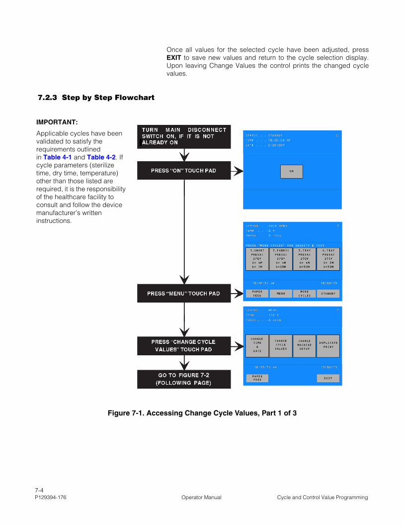
Once all values for the selected cycle have been adjusted, pressEXIT to save new values and return to the cycle selection display.Upon leaving Change Values the control prints the changed cyclevalues.
7.2.3 Step by Step Flowchart
Figure 7-1. Accessing Change Cycle Values, Part 1 of 3
IMPORTANT:
Applicable cycles have been validated to satisfy the requirements outlined in Table 4-1 and Table 4-2. If cycle parameters (sterilize time, dry time, temperature) other than those listed are required, it is the responsibility of the healthcare facility to consult and follow the device manufacturer’s written instructions.
7-2
7-4P129394-176 Operator Manual Cycle and Control Value Programming

FIGURE 7-2, below, is a continuation of the flow chart in FIGURE 7-1.
Figure 7-2. Change Cycle Values Procedure, Part 2 of 3FIGURE 7-3 is a continuation of the flow chart in FIGURE 7-2.
Comments:
Important: Pressing EXITcauses the sterilizer to leaveChange Values, saving anychanges made to the pointwhere EXIT was pressed.
7-3
If cycle is locked out, AccessCode Screen (#37) appears.The access code must beentered using the followingprocedure:
• If the code is known, enter it using the touch screen key pad. Once the entire four digit code has been entered, press the ENTER touch screen pad. The access code digits are not displayed.
If the code is not known, pressMENU to return to theprevious screen.
A printout of cycle values andthe cycle count is provided bypressing PRINT VALUES.Any changed cycle valuesand the cycle count areautomatically printed afterreturning to screen #10 fromscreen #11.
7-5Cycle and Control Value Programming Operator Manual P129394-176

7-6P129394-176 Operator Manual Cycle and Control Value Programming
Figure 7-3. Change Cycle Values Procedure, Part 3 of 3
Comments:
Select Value
• Press NAME touchpad to change cycle type
• Press TEMP touchpad change sterilization exposure temperature.
• Press STER touchpad to change Sterilization Exposure Time
• Press DRY touchpad to change Drying Time
7-2
TEMP, STER or DRY valuescan be entered or changedusing the numeric touchpads.Arrow touchpads move thecursor position (for editing)left or right.

7.3 Entering CustomCycle Names
Figure 7-4. Enter or Change Custom Cycle Names
CUSTOM NAMES are used toadd descriptive text to thecycle selection buttons.
• CLEAR button erases all text entered.
• <- and -> buttons move the cursor position left or right.
EXAMPLE:
7-7Cycle and Control Value Programming Operator Manual P129394-176
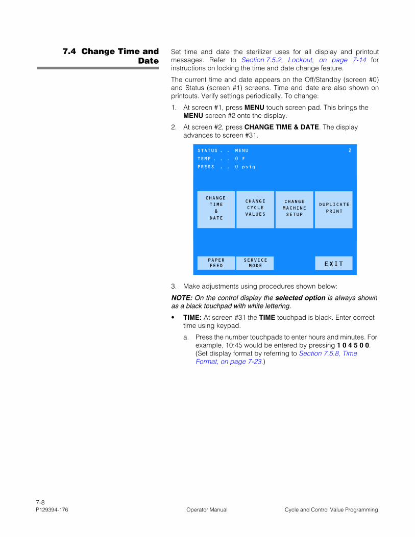
7.4 Change Time andDate
Set time and date the sterilizer uses for all display and printoutmessages. Refer to Section 7.5.2, Lockout, on page 7-14 forinstructions on locking the time and date change feature.
The current time and date appears on the Off/Standby (screen #0)and Status (screen #1) screens. Time and date are also shown onprintouts. Verify settings periodically. To change:
1. At screen #1, press MENU touch screen pad. This brings the MENU screen #2 onto the display.
2. At screen #2, press CHANGE TIME & DATE. The display advances to screen #31.
3. Make adjustments using procedures shown below:
NOTE: On the control display the selected option is always shownas a black touchpad with white lettering.
• TIME: At screen #31 the TIME touchpad is black. Enter correct time using keypad.
a. Press the number touchpads to enter hours and minutes. For example, 10:45 would be entered by pressing 1 0 4 5 0 0. (Set display format by referring to Section 7.5.8, Time Format, on page 7-23.)
EXIT
CHANGE
CYCLE
VALUES
CHANGE
MACHINE
SETUP
STATUS . . MENU 2
TEMP . . . 0 F
PRESS . . 0 psig
CHANGE
TIME DUPLICATE
DATE
PAPER SERVICEFEED MODE
7-8P129394-176 Operator Manual Cycle and Control Value Programming
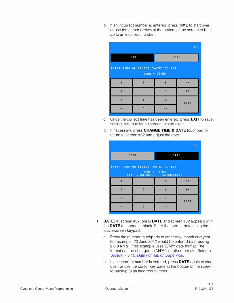
b. If an incorrect number is entered, press TIME to start over, or use the cursor arrows at the bottom of the screen to back up to an incorrect number.
c. Once the correct time has been entered, press EXIT to save setting, return to Menu screen to start clock.
d. If necessary, press CHANGE TIME & DATE touchpad to return to screen #32 and adjust the date.
• DATE: At screen #32, press DATE and screen #32 appears with the DATE touchpad in black. Enter the correct date using the touch-screen keypad.
a. Press the number touchpads to enter day, month and year. For example, 20 June 2012 would be entered by pressing 2 0 0 6 1 2. (This example uses D/M/Y date format. The format can be changed to M/D/Y, or other formats. Refer to Section 7.5.12, Date Format, on page 7-28.
b. If an incorrect number is entered, press DATE again to start over, or use the cursor key pads at the bottom of the screen to backup to an incorrect number.
ENTER TIME OR SELECT "DATE" TO SET
TIME = 00:00
ENTER TIME OR SELECT "DATE" TO SET
TIME = 00:00
31
TIME DATE
1 2 3 AM
4 5 6 PM
7 8 9EXIT
<- 0 ->
ENTER TIME OR SELECT "DATE" TO SET
DATE = 00/00/00 (WEDNESDAY)
ENTER TIME OR SELECT "DATE" TO SET
TIME = 00:00
32
TIME DATE
1 2 3 AM
4 5 6 PM
7 8 9EXIT
<- 0 ->
7-9Cycle and Control Value Programming Operator Manual P129394-176

c. Once the correct date has been entered, press EXIT to return to screen #1.
NOTE: The day of the week is automatically understood andregistered by the control.
ENTER TIME OR SELECT "DATE" TO SET
DATE = 00/00/00 (WEDNESDAY)
ENTER TIME OR SELECT "DATE" TO SET
TIME = 00:00
32
TIME DATE
1 2 3 AM
4 5 6 PM
7 8 9EXIT
<- 0 ->
7-10P129394-176 Operator Manual Cycle and Control Value Programming
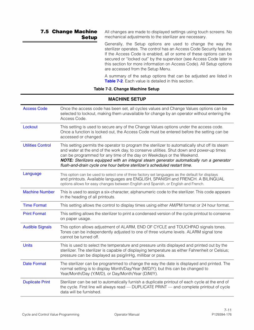
7.5 Change MachineSetup
All changes are made to displayed settings using touch screens. Nomechanical adjustments to the sterilizer are necessary.
Generally, the Setup options are used to change the way thesterilizer operates. The control has an Access Code Security feature.If the Access Code is enabled, all or some of these options can besecured or “locked out” by the supervisor (see Access Code later inthis section for more information on Access Code). All Setup optionsare accessed from the Setup Menu.
A summary of the setup options that can be adjusted are listed inTable 7-2. Each value is detailed in this section.
Table 7-2. Change Machine Setup
MACHINE SETUP
Access Code Once the access code has been set, all cycles values and Change Values options can be selected to lockout, making them unavailable for change by an operator without entering the Access Code.
Lockout This setting is used to secure any of the Change Values options under the access code. Once a function is locked out, the Access Code must be entered before the setting can be accessed or changed.
Utilities Control This setting permits the operator to program the sterilizer to automatically shut off its steam and water at the end of the work day, to conserve utilities. Shut down and power-up times can be programmed for any time of the day on Weekdays or the Weekend. NOTE: Sterilizers equipped with an integral steam generator automatically run a generatorflush-and-drain cycle one hour before sterilizer’s scheduled restart time.
Language This option can be used to select one of three factory set languages as the default for displaysand printouts. Available languages are ENGLISH, SPANISH and FRENCH. A BILINGUALoptions allows for easy changes between English and Spanish, or English and French.
Machine Number This is used to assign a six-character, alphanumeric code to the sterilizer. This code appears in the heading of all printouts.
Time Format This setting allows the control to display times using either AM/PM format or 24 hour format.
Print Format This setting allows the sterilizer to print a condensed version of the cycle printout to conserve on paper usage.
Audible Signals This option allows adjustment of ALARM, END OF CYCLE and TOUCHPAD signals tones. Tones can be independently adjusted to one of three volume levels. ALARM signal tone cannot be turned off.
Units This is used to select the temperature and pressure units displayed and printed out by the sterilizer. The sterilizer is capable of displaying temperature as either Fahrenheit or Celsius; pressure can be displayed as psig/inHg, millibar or psia.
Date Format The sterilizer can be programmed to change the way the date is displayed and printed. The normal setting is to display Month/Day/Year (M/D/Y); but this can be changed to Year/Month/Day (Y/M/D), or Day/Month/Year (D/M/Y).
Duplicate Print Sterilizer can be set to automatically furnish a duplicate printout of each cycle at the end of the cycle. First line will always read — DUPLICATE PRINT — and complete printout of cycle data will be furnished.
7-11Cycle and Control Value Programming Operator Manual P129394-176

7.5.1 Access Code This setup option is used to control access to the adjustmentfunctions of the sterilizer control.
• When the Access Code is ON, a four-digit code must be entered before changing any locked-out functions.
• Functions are selected for lock out by supervisor or operator.
Enabling or Disabling theAccess Code
1. To access this utility, press CHANGE MACHINE SETUP touchpad from the Menu screen at the operating end of the sterilizer.
2. The display changes to the Change Machine Setup screen (#20). Press the touchpad labeled ACCESS CODE. The screen changes to the Access Code screen (#21).
3. If the Access Code option is already turned on, the highlighted touchpad is CODE REQUIRED. If the Access Code is not on, highlighted touchpad is CODE NOT REQUIRED. Additionally, if the Access Code is not enabled, the LOCKOUT touchpad does not appear on screen #20. Press appropriate touchpad if you want to change Access Code status, or press EXIT, if no change is necessary.
EXIT
CHANGE
CYCLE
VALUES
CHANGE
MACHINE
SETUP
STATUS . . MENU 2
TEMP . . . 0 F
PRESS . . 0 psig
CHANGE
TIME DUPLICATE
DATE
PAPER SERVICEFEED MODE
20SELECT MACHINE SETUP TO REVIEW OR CHANGE
LOCKOUT ACCESS CODE
UTILITIES CONTROL
LANGUAGE
MACHINE NUMBER
TIME FORMAT
PRINT FORMAT
AUDIBLE SIGNALS
UNITS DATE FORMAT
DUPLICATE PRINT
EXIT
7-12P129394-176 Operator Manual Cycle and Control Value Programming
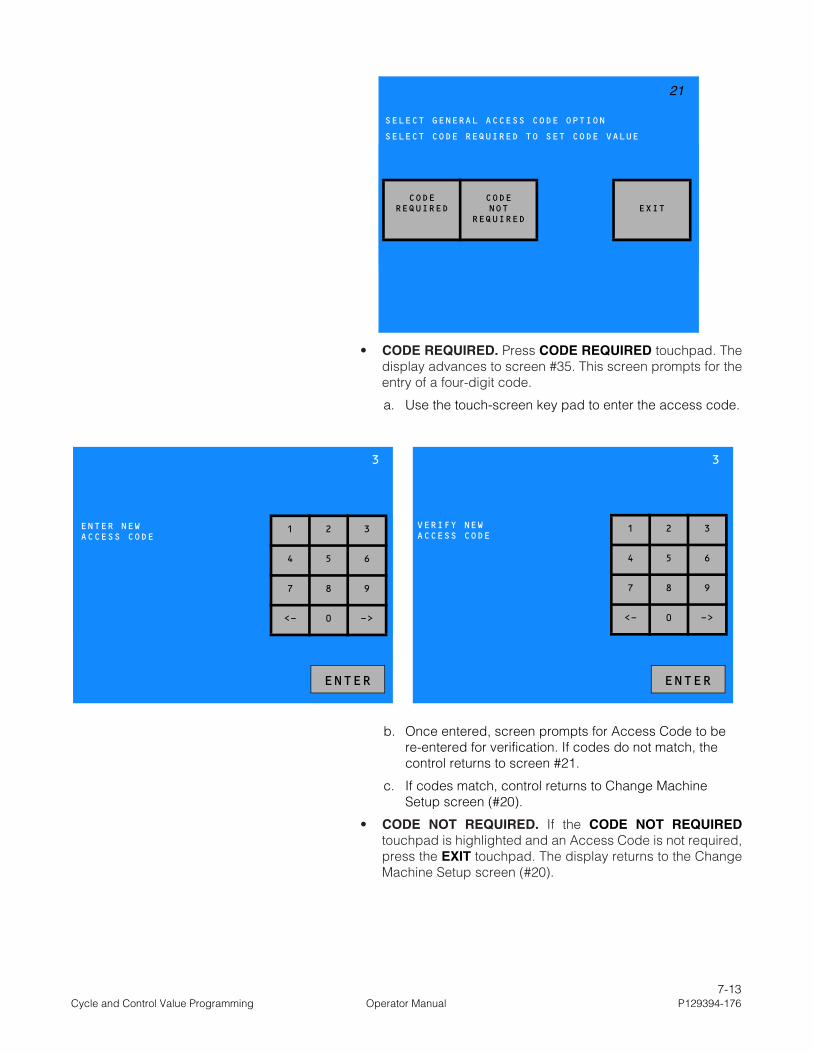
• CODE REQUIRED. Press CODE REQUIRED touchpad. Thedisplay advances to screen #35. This screen prompts for theentry of a four-digit code.
a. Use the touch-screen key pad to enter the access code.
b. Once entered, screen prompts for Access Code to be re-entered for verification. If codes do not match, the control returns to screen #21.
c. If codes match, control returns to Change Machine Setup screen (#20).
• CODE NOT REQUIRED. If the CODE NOT REQUIREDtouchpad is highlighted and an Access Code is not required,press the EXIT touchpad. The display returns to the ChangeMachine Setup screen (#20).
21
SELECT GENERAL ACCESS CODE OPTION
SELECT CODE REQUIRED TO SET CODE VALUE
CODE REQUIRED
CODE NOT
REQUIREDEXIT
ENTER NEWACCESS CODE
ENTER
1 2 3
4 5 6
7 8 9
<- 0 ->
ENTER
3
1 2 3
4 5 6
7 8 9
<- 0 ->
3
VERIFY NEWACCESS CODE
7-13Cycle and Control Value Programming Operator Manual P129394-176
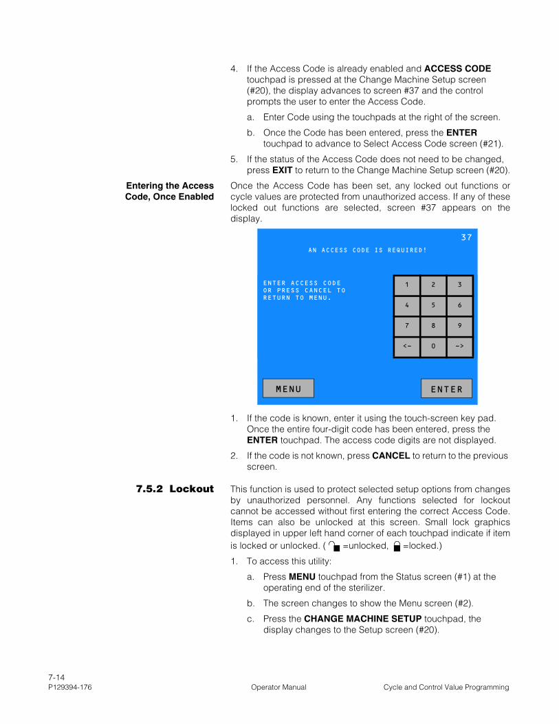
4. If the Access Code is already enabled and ACCESS CODE touchpad is pressed at the Change Machine Setup screen (#20), the display advances to screen #37 and the control prompts the user to enter the Access Code.
a. Enter Code using the touchpads at the right of the screen.
b. Once the Code has been entered, press the ENTER touchpad to advance to Select Access Code screen (#21).
5. If the status of the Access Code does not need to be changed, press EXIT to return to the Change Machine Setup screen (#20).
Entering the AccessCode, Once Enabled
Once the Access Code has been set, any locked out functions orcycle values are protected from unauthorized access. If any of theselocked out functions are selected, screen #37 appears on thedisplay.
1. If the code is known, enter it using the touch-screen key pad. Once the entire four-digit code has been entered, press the ENTER touchpad. The access code digits are not displayed.
2. If the code is not known, press CANCEL to return to the previous screen.
7.5.2 Lockout This function is used to protect selected setup options from changesby unauthorized personnel. Any functions selected for lockoutcannot be accessed without first entering the correct Access Code.Items can also be unlocked at this screen. Small lock graphicsdisplayed in upper left hand corner of each touchpad indicate if itemis locked or unlocked. ( =unlocked, =locked.)
1. To access this utility:
a. Press MENU touchpad from the Status screen (#1) at the operating end of the sterilizer.
b. The screen changes to show the Menu screen (#2).
c. Press the CHANGE MACHINE SETUP touchpad, the display changes to the Setup screen (#20).
AN ACCESS CODE IS REQUIRED!
ENTER ACCESS CODEOR PRESS CANCEL TO RETURN TO MENU.
ENTERMENU
1 2 3
4 5 6
7 8 9
<- 0 ->
37
7-14P129394-176 Operator Manual Cycle and Control Value Programming
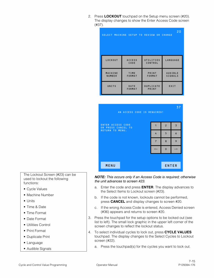
2. Press LOCKOUT touchpad on the Setup menu screen (#20). The display changes to show the Enter Access Code screen (#37).
NOTE: This occurs only if an Access Code is required; otherwisethe unit advances to screen #23.
a. Enter the code and press ENTER. The display advances to the Select Items to Lockout screen (#23).
b. If the code is not known, lockouts cannot be performed, press CANCEL and display changes to screen #20.
c. If the wrong Access Code is entered, Access Denied screen (#36) appears and returns to screen #20.
3. Press the touchpad for the setup options to be locked out (see list to left). The small lock graphic in the upper left corner of the screen changes to reflect the lockout status.
4. To select individual cycles to lock out, press CYCLE VALUES touchpad. The display changes to the Select Cycles to Lockout screen (#22).
a. Press the touchpad(s) for the cycles you want to lock out.
SELECT MACHINE SETUP TO REVIEW OR CHANGE20
LOCKOUT ACCESS CODE
UTILITIES CONTROL
LANGUAGE
MACHINE NUMBER
TIME FORMAT
PRINTFORMAT
AUDIBLE SIGNALS
UNITS DATE FORMAT
DUPLICATE PRINT
EXIT
AN ACCESS CODE IS REQUIRED!
ENTER ACCESS CODEOR PRESS CANCEL TO RETURN TO MENU.
ENTER
37
MENU
1 2 3
4 5 6
7 8 9
<- 0 ->
The Lockout Screen (#23) can be used to lockout the following functions:
• Cycle Values
• Machine Number
• Units
• Time & Date
• Time Format
• Date Format
• Utilities Control
• Print Format
• Duplicate Print
• Language
• Audible Signals
7-15Cycle and Control Value Programming Operator Manual P129394-176
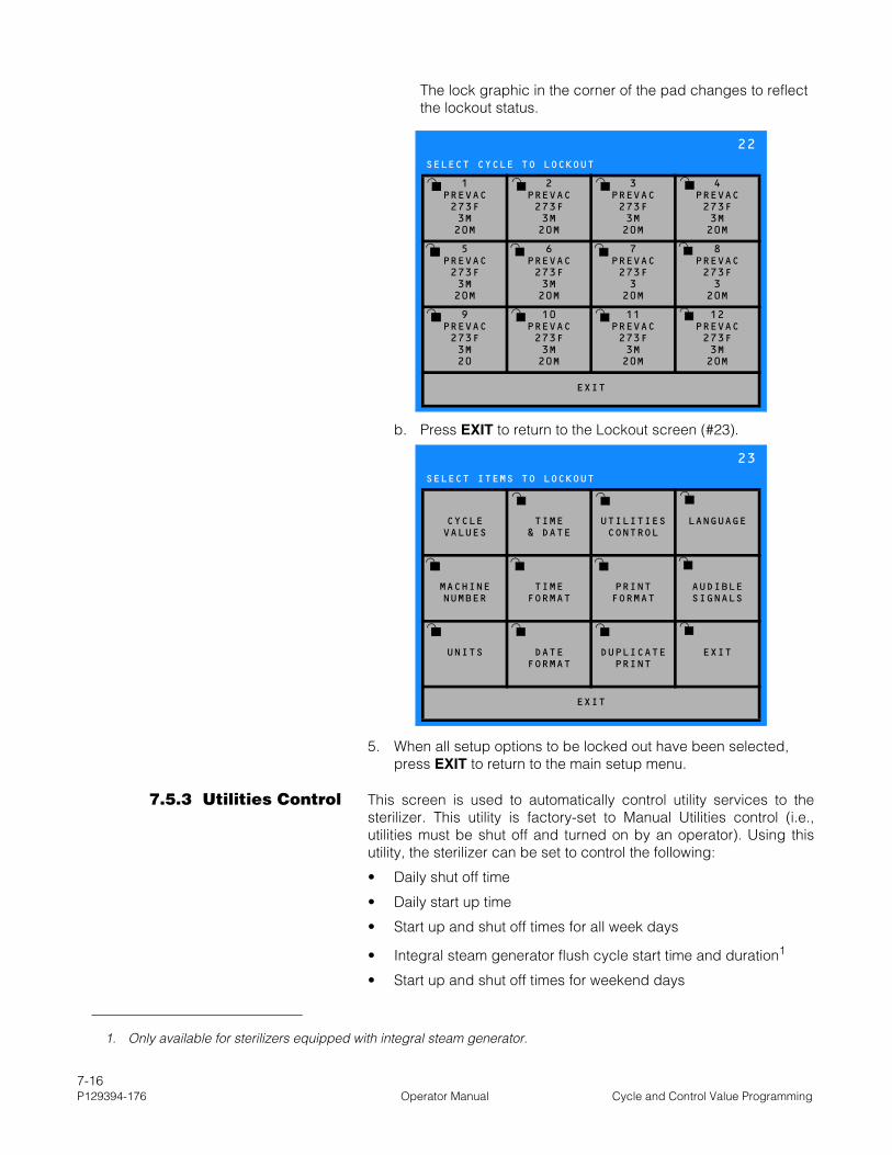
The lock graphic in the corner of the pad changes to reflect the lockout status.
b. Press EXIT to return to the Lockout screen (#23).
5. When all setup options to be locked out have been selected, press EXIT to return to the main setup menu.
7.5.3 Utilities Control This screen is used to automatically control utility services to thesterilizer. This utility is factory-set to Manual Utilities control (i.e.,utilities must be shut off and turned on by an operator). Using thisutility, the sterilizer can be set to control the following:
• Daily shut off time
• Daily start up time
• Start up and shut off times for all week days
• Integral steam generator flush cycle start time and duration1
• Start up and shut off times for weekend days
SELECT CYCLE TO LOCKOUT
1PREVAC273F3M20M
2PREVAC273F3M20M
3PREVAC273F3M20M
4PREVAC273F3M20M
5PREVAC273F3M20M
6PREVAC273F3M20M
7PREVAC273F3
20M
8PREVAC273F3
20M
9PREVAC273F3M20
10PREVAC273F3M20M
11PREVAC273F3M20M
12PREVAC273F3M20M
EXIT
22
SELECT ITEMS TO LOCKOUT
CYCLEVALUES
TIME& DATE
UTILITIESCONTROL
LANGUAGE
MACHINENUMBER
TIMEFORMAT
PRINT FORMAT
AUDIBLESIGNALS
UNITS DATEFORMAT
DUPLICATE PRINT
EXIT
EXIT
23
1. Only available for sterilizers equipped with integral steam generator.
7-16P129394-176 Operator Manual Cycle and Control Value Programming

Screen displayed in Auto Utility Shutdown.
If the sterilizer is processing a cycle when the utility shut down timearrives, the cycle completes before the sterilizer shuts itself off. Thesterilizer can be manually restarted for 30 minutes at any time duringutility shutdown by pressing the ON touchpad at the Off/Standbyscreen (#0).
1. To access this utility, press the MENU touchpad from the Main Status screen (#1) at the operating end of the sterilizer.
2. The display changes to the Menu screen. Press the CHANGE MACHINE SETUP touchpad. The display changes to the Setup screen. Press the UTILITIES CONTROL touchpad. The screen changes to the Utilities Control screen (#39).
• MANUAL UTILITIES CONTROL. This is the defaultcondition for the sterilizer. Press this touchpad to cancel allautomatic utilities controls. Press EXIT to return to theChange Machine Setup screen (#20).
• AUTOMATIC UTILITIES CONTROL. Press this to advanceto screen #34.
STATUS . . UTILITIES SHUTDOWN 40
TIME . . . 10:20:00 AM
DATE . . . 2/20/94 TUESDAY
RESTART: 6:00 AM WEDNESDAY
UTILITIES WILL AUTOMATICALLY TURN ON AT
RESTART TIME.
PRESS ON TO TURN ON UTILITIES SOONER. UTILITIES WILL REMAIN ON UNTIL THE ENDOF THE CYCLE.
ON
SELECT UTILITIES CONTROL OPTIONSELECT AUTOMATIC TO SET AUTOMATIC TIMES
39
GENERATORFLUSHCONTROL
MANUALUTILITIESCONTROL
AUTOMATICUTILITIESCONTROL
EXIT
7-17Cycle and Control Value Programming Operator Manual P129394-176
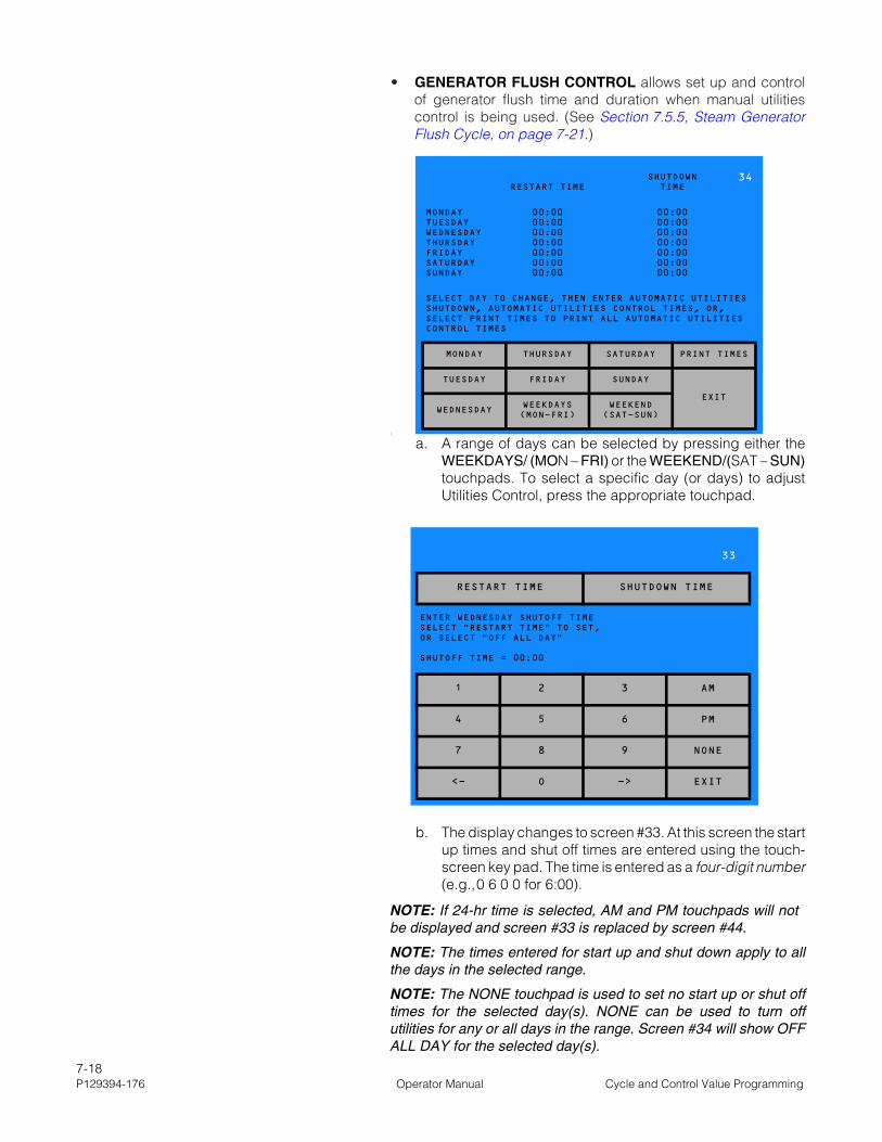
7-18
• GENERATOR FLUSH CONTROL allows set up and controlof generator flush time and duration when manual utilitiescontrol is being used. (See Section 7.5.5, Steam GeneratorFlush Cycle, on page 7-21.)
•
a. A range of days can be selected by pressing either theWEEKDAYS/ (MON – FRI) or the WEEKEND/(SAT – SUN)touchpads. To select a specific day (or days) to adjustUtilities Control, press the appropriate touchpad.
b. The display changes to screen #33. At this screen the startup times and shut off times are entered using the touch-screen key pad. The time is entered as a four-digit number(e.g.,0 6 0 0 for 6:00).
NOTE: If 24-hr time is selected, AM and PM touchpads will notbe displayed and screen #33 is replaced by screen #44.
NOTE: The times entered for start up and shut down apply to allthe days in the selected range.
NOTE: The NONE touchpad is used to set no start up or shut offtimes for the selected day(s). NONE can be used to turn offutilities for any or all days in the range. Screen #34 will show OFFALL DAY for the selected day(s).
RESTART TIMESHUTDOWN
TIME34
MONDAYTUESDAYWEDNESDAYTHURSDAYFRIDAYSATURDAYSUNDAY
00:0000:0000:0000:0000:0000:0000:00
00:0000:0000:0000:0000:0000:0000:00
SELECT DAY TO CHANGE, THEN ENTER AUTOMATIC UTILITIES SHUTDOWN, AUTOMATIC UTILITIES CONTROL TIMES, OR, SELECT PRINT TIMES TO PRINT ALL AUTOMATIC UTILITIES CONTROL TIMES
MONDAY THURSDAY SATURDAY PRINT TIMES
TUESDAY FRIDAY SUNDAY
EXIT
WEDNESDAYWEEKDAYS(MON-FRI)
WEEKEND(SAT-SUN)
33
RESTART TIME SHUTDOWN TIME
ENTER WEDNESDAY SHUTOFF TIMESELECT "RESTART TIME" TO SET,OR SELECT "OFF ALL DAY"
SHUTOFF TIME = 00:00
1 2 3 AM
4 5 6 PM
7 8 9 NONE
<- O -> EXIT
P129394-176 Operator Manual Cycle and Control Value Programming

Once the start up and shut off times have been selected, press EXITto return to the Change Machine Setup screen (#20).
See the following example to program automatic utilities control:
Example: The sterilizer is to be used five days a week (Mondaythrough Friday), with a daily start up time of 07:00 and a shut downtime of 18:30. The sterilizer will also be used Saturday morning from06:00 through 12:00.
1. At screen #20, press the UTILITIES CONTROL touchpad. 2. At screen #39, press the AUTOMATIC UTILITIES CONTROL
touchpad.
3. At screen #34, press the WEEKDAYS touchpad.
a. Enter the 07:00 restart time by pressing 0 7 0 0 touchpads.
b. Press the SHUTOFF TIME touchpad.
c. Enter the 18:30 shut off time by pressing 1 8 3 0 touchpads.
d. Press the EXIT touchpad.
e. At screen #34 press the SATURDAY touchpad.
f. Enter the Saturday restart time by pressing the 0 6 0 0 touchpads.
g. Enter the Saturday shut off time by pressing the 1 2 0 0 touchpads.
h. Press EXIT.
i. At Screen #34, press SUNDAY, and at screen #33 press NONE.
The utilities control function is now programmed to turn thesterilizer’s utilities on at 07:00 and off at 18:30 Monday throughFriday. On Saturday the utilities will be on between 06:00 and 12:00.Utilities will be off all day Sunday.
NOTE: Some sterilizers are operated exclusively on the night shift. In such cases, it may be useful to set shutdown and restart times so the sterilizer operates during the evening hours and is shut down during the day. The diagram below shows one example of how this can be done.
Day-ShiftHours
Night-Shift Hours
Utilities Control Programming Turns
Sterilizer Onat 5:00 pm
Utilities Control Programming Turns
Sterilizer Off at 11:30 pm
7-19Cycle and Control Value Programming Operator Manual P129394-176

7.5.4 Steam Generator Flushand Drain Set Up
If a building steam source is not available, the sterilizer may beequipped with an electric steam generator. The generatorautomatically converts water to steam using electric heat. The steamcreated is then used to power the sterilizer.
Steam generators are highly susceptible to mineral scaling if thesupplied water has any level of hardness. Refer to Table 7-3 forwater quality requirements.
Important: Regardless of the hardness level of supplied water, thegenerator must be flushed every day before use to prevent mineralscaling or carryover of debris into the chamber.
NOTE: Warranty on this steam generator will be voided unless dailyflushing procedures are performed.
The sterilizer will automatically flush the generator. SeeSection 7.5.3, Utilities Control, on page 7-16 for information onsetting the duration and start time of the automatic generator flush.
NOTE: The generator must be flushed every day before use.
Table 7-3. Required Feed Water Quality for Carbon Steel Steam Generators
ConditionNominal
ConditionsMaximum
Conditions
Temperature as supplied 140° F (60° C)
Total Hardness as CaCO3*
* 17.1 mg/L = 1 grain hardness
0-17 mg/L 130 mg/L
Total Dissolved Solids 50-150 mg/L 250 mg/L
Total Alkalinity as CaCO3 50-100 mg/L 180 mg/L
pH 6.8-7.5 6.5-8.5
Total Silica 0.1-1.0 mg/L 2.5 mg/L
Resistivity - ohms/cm 2000-6000 26000
7-20P129394-176 Operator Manual Cycle and Control Value Programming

7.5.5 Steam GeneratorFlush Cycle
The FLUSH TIME function shown on Screen #48 is active onlywhen Automatic Utilities Control has been enabled (seeSection 7.5.3, Utilities Control, on page 7-16). The FLUSHDURATION set up function is always used when the sterilizer isequipped with an integral steam generator. Flush duration applies ifutilities are being controlled automatically or manually.
1. Select the Generator Flush Option from screen #39. The control advances to the generator flush and drain scheduling screen (#48).
2. At screen #48, select FLUSH TIME and schedule the time of day for the generator flush and drain.
3. Once the time day for the generator flush sequence has been scheduled, press EXIT to return to screen #48.
ENTER GENERATOR FLUSH TIMESSELECT "FLUSH TIME" ORSELECT "FLUSH DURATION " TO SET
FLUSH TIME = 00:00 AM
48
FLUSH TIME
1 2 3 AM
4 5 6 PM
7 8 9EXIT
<- 0 ->
FLUSH DURATION
Figure 7-5. Generator Flush Duration Time Control Screen
ENTER GENERATOR FLUSH TIMES.ENTER "FLUSH TIME" OR SELECT "FLUSH DURATION" TO SET.
FLUSH DURATION = 5:00 M : S
49
FLUSH TIME FLUSH DURATION
1 2 3
EXIT
4 5 6
7 8 9
<- 0 ->
Refer to Section 7.5.4, Steam Generator Flushand Drain Set Up, on page 7-20.
Use the keypad to enter the duration length forthe FLUSH phase of the cycle.
7-21Cycle and Control Value Programming Operator Manual P129394-176
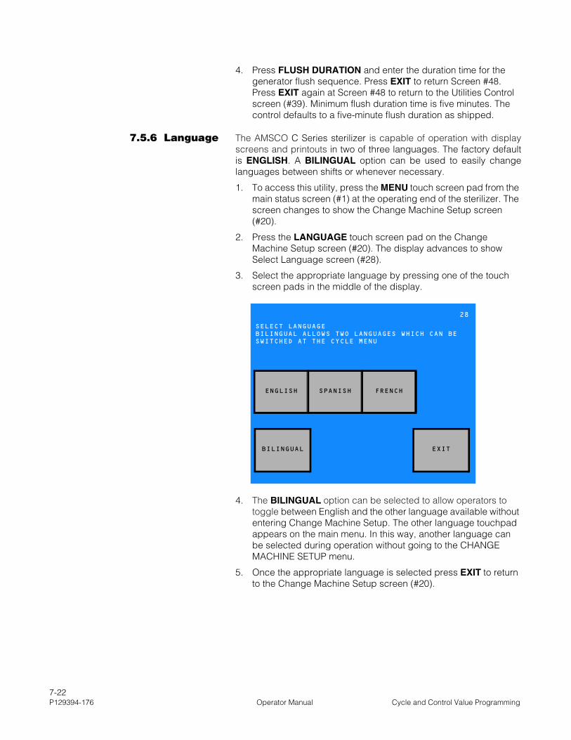
4. Press FLUSH DURATION and enter the duration time for the generator flush sequence. Press EXIT to return Screen #48. Press EXIT again at Screen #48 to return to the Utilities Control screen (#39). Minimum flush duration time is five minutes. The control defaults to a five-minute flush duration as shipped.
7.5.6 Language The AMSCO C Series sterilizer is capable of operation with displayscreens and printouts in two of three languages. The factory defaultis ENGLISH. A BILINGUAL option can be used to easily changelanguages between shifts or whenever necessary.
1. To access this utility, press the MENU touch screen pad from the main status screen (#1) at the operating end of the sterilizer. The screen changes to show the Change Machine Setup screen (#20).
2. Press the LANGUAGE touch screen pad on the Change Machine Setup screen (#20). The display advances to show Select Language screen (#28).
3. Select the appropriate language by pressing one of the touch screen pads in the middle of the display.
4. The BILINGUAL option can be selected to allow operators to toggle between English and the other language available without entering Change Machine Setup. The other language touchpad appears on the main menu. In this way, another language can be selected during operation without going to the CHANGE MACHINE SETUP menu.
5. Once the appropriate language is selected press EXIT to return to the Change Machine Setup screen (#20).
SELECT LANGUAGEBILINGUAL ALLOWS TWO LANGUAGES WHICH CAN BE SWITCHED AT THE CYCLE MENU
28
ENGLISH SPANISH FRENCH
BILINGUAL EXIT
7-22P129394-176 Operator Manual Cycle and Control Value Programming
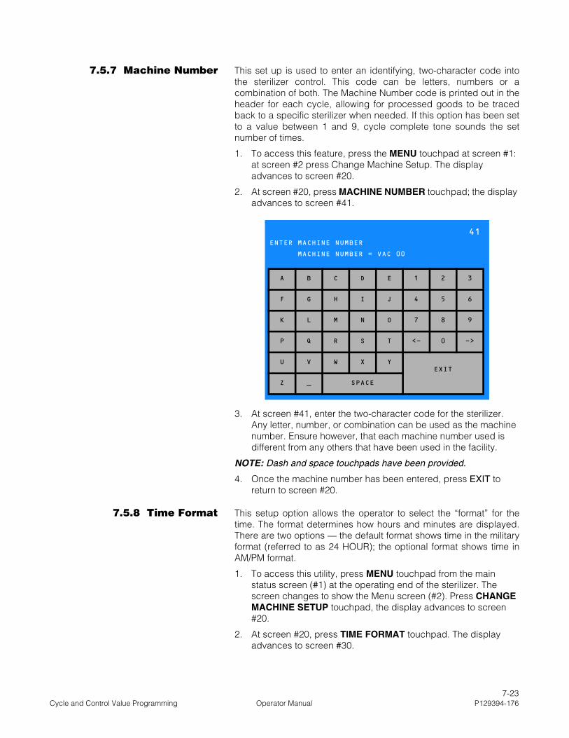
7.5.7 Machine Number This set up is used to enter an identifying, two-character code intothe sterilizer control. This code can be letters, numbers or acombination of both. The Machine Number code is printed out in theheader for each cycle, allowing for processed goods to be tracedback to a specific sterilizer when needed. If this option has been setto a value between 1 and 9, cycle complete tone sounds the setnumber of times.
1. To access this feature, press the MENU touchpad at screen #1: at screen #2 press Change Machine Setup. The display advances to screen #20.
2. At screen #20, press MACHINE NUMBER touchpad; the display advances to screen #41.
3. At screen #41, enter the two-character code for the sterilizer. Any letter, number, or combination can be used as the machine number. Ensure however, that each machine number used is different from any others that have been used in the facility.
NOTE: Dash and space touchpads have been provided.
4. Once the machine number has been entered, press EXIT to return to screen #20.
7.5.8 Time Format This setup option allows the operator to select the “format” for thetime. The format determines how hours and minutes are displayed.There are two options — the default format shows time in the militaryformat (referred to as 24 HOUR); the optional format shows time inAM/PM format.
1. To access this utility, press MENU touchpad from the main status screen (#1) at the operating end of the sterilizer. The screen changes to show the Menu screen (#2). Press CHANGE MACHINE SETUP touchpad, the display advances to screen #20.
2. At screen #20, press TIME FORMAT touchpad. The display advances to screen #30.
ENTER MACHINE NUMBER
MACHINE NUMBER = VAC 00
41
A B C D E 1 2 3
F G H I J 4 5 6
K L M N O 7 8 9
P Q R S T <- 0 ->
U V W X YEXIT
Z _ SPACE
7-23Cycle and Control Value Programming Operator Manual P129394-176

3. Select the appropriate time format by pressing one of the two touchpads in the lower half of the display.
• AM / PM – This is the standard civilian time format.
• 24 HOUR – This is a 24 hour format associated with militarytimekeeping.
4. Once the appropriate format has been selected, or if format does not need to be changed, press EXIT to return to the Change Machine Setup screen (#20).
7.5.9 Print Format This setup option allows the operator to select the cycle printout“format.” The format determines the type of printout the sterilizerprovides during processing. Two options are available. The defaultFULL format provides status prints at each transition point in thecycle, plus additional status at interval points during each phase ofthe cycle. The optional CONDENSED format provides a cyclesummary and complete time, without additional status prints at cycleinterval points. The CONDENSED format can be used to conserveprinter paper. Refer to Figure 7-6.
1. To access this utility, press the MENU touchpad from the Status screen (#1) at the operating end of the sterilizer. The screen changes to show the menu screen (#2). Press the CHANGE MACHINE SETUP touchpad.
2. Press PRINT FORMAT touchpad on the Change Machine Setup screen (#20); the display advances to screen #29.
SELECT TIME FORMAT
AM/PM 24 HOUR EXIT
30
7-24P129394-176 Operator Manual Cycle and Control Value Programming

3. Select the appropriate print format by pressing one of the two touchpads in the lower half of the display.
• FULL – This is the standard format providing a status print for each phase of the cycle and status prints at the predetermined Print Interval.
• CONDENSED – This format provides an abbreviated cycle status printout.
4. Once the appropriate format is selected, press EXIT to return to the Change Machine Setup screen (#20).
SELECT PRINT FORMAT
FULL CONDENSED EXIT
29
7-25Cycle and Control Value Programming Operator Manual P129394-176

Figure 7-6. Sample Full and Condensed Printouts
Full Printout (Typical)
Condensed Printout (Typical)
7-26P129394-176 Operator Manual Cycle and Control Value Programming

7.5.10 Audible Signals This setup option allows the operator to adjust selected audiblesignals heard at the sterilizer control. Three signals can be adjusted.Touchpad and end of cycle signals can be adjusted to one of threevolume levels or turned off. Only the volume level of the Alarm signalcan be adjusted. The Alarm signal cannot be turned off.
1. To access this utility, press the MENU touchpad from the Status screen (#1), at the operating end of the sterilizer. The screen changes to show Change Machine Setup screen (#20).
2. Press CHANGE MACHINE SETUP on the Menu screen, then AUDIBLE SIGNALS on the Setup screen (#20). The display advances to the Audible Signals setup screen (#24).
3. Select the signal you wish to adjust by pressing the appropriate touchpad in the upper half of the screen.
• TOUCHPAD – This is the signal sounded by the controlwhenever anyone presses a touchpad.
• END OF CYCLE – This is the signal heard when a cycle iscomplete.
• ALARM – This is a two-tone signal heard during abnormalconditions.
a. Each audible signal can be adjusted for volume.
1) First press the touchpad for the selected type of signal(e.g., ALARM, END OF CYCLE or TOUCHPAD).
2) Once the signal has been selected, press the requiredvolume level (e.g., LOW, MEDIUM or HIGH).
b. TOUCHPAD and END OF CYCLE provide an OFF setting. The ALARM signal cannot be turned off.
4. Once the appropriate Audible Signals and Signal volumes have been selected, or if these do not need to be changed, press EXIT to return to the Change Machine Setup screen (#20).
TOUCHPAD END OF CYCLE
ALARM
SELECT VOLUME LEVELOR SELECT ANOTHER AUDIBLE SIGNAL
OFF LOWEXIT
MEDIUM HIGH
24
7-27Cycle and Control Value Programming Operator Manual P129394-176

7.5.11 Units This feature is used to select or change the units the sterilizer useswhen displaying and printing chamber temperature and pressure.This function allows selection of either Fahrenheit or Celsius units fordisplaying and printing temperature. Pressure units can be changedbetween psig/inHg, mbar or psia. Changing units does not requirerecalibrating the sterilizer.
1. To access this feature, press the Menu touch-screen pad at screen #1; at screen #2 press CHANGE MACHINE SETUP. The display advances to screen #20.
2. At screen #20, press UNITS touch-screen pad; the display advances to screen #42.
3. At screen #42, press the appropriate touchpad for the type of unit or units required. Once all units have been selected, press EXIT to return to screen #20.
7.5.12 Date Format This setup option allows the operator to select the “format” for thedate. The format determines the order in which the month, day andyear are displayed. There are three options, and the option selectedis a matter of either preference or geographical location.
1. To access this utility, press the MENU touchpad from the Status menu (#1). Press the CHANGE MACHINE SETUP touchpad, the control advances to the Change Machine Setup screen (#20).
2. Press DATE FORMAT touchpad at screen #20; the display advances to screen #26.
3. Select the date format appropriate for your location by pressing one of the six touchpads in the lower half of the display.
• M-D-Y – Month-Day-Year
• D-M-Y – Day-Month-Year
SELECT TEMPERATURE AND PRESSURE UNITS
42
FAHRENHEIT CELSIUSEXIT
psia psig/inHG mbar
7-28P129394-176 Operator Manual Cycle and Control Value Programming

• Y-M-D – Year-Month-Day
• MON-D-Y – Month-Day-Year*
• D-MON-Y – Day-Month-Year*
• Y-MON-D – Year-Month-Day*
* When selecting the format touchpads in the bottom row, MON = 3 letterabbreviation of the month.
4. Once the appropriate format has been selected, or if format does not need to be changed, press EXIT to return to the Change Machine Setup screen (#20).
7.5.13 Duplicate Print This setup option allows the Customer to select whether the sterilizerautomatically supplies an extra printout at the end of the cycle. Thereare two options; the option selected depends on operatingrequirements in your facility. The default setting is for no duplicateprint.
1. To access this utility, press MENU touchpad from the main status screen (#1) at the operating end of the sterilizer. The screen changes to show the menu screen (#2). Press CHANGE MACHINE SETUP touchpad; the display advances to screen #20.
SELECT DATE FORMAT
D = DAY
M = MONTH
MON = 3 LETTER ABBREVIATION FOR MONTH
Y = YEAR
26
M-D-Y D-M-Y Y-M-DEXIT
MON-D-Y D-MON-Y Y-MON-D
7-29Cycle and Control Value Programming Operator Manual P129394-176
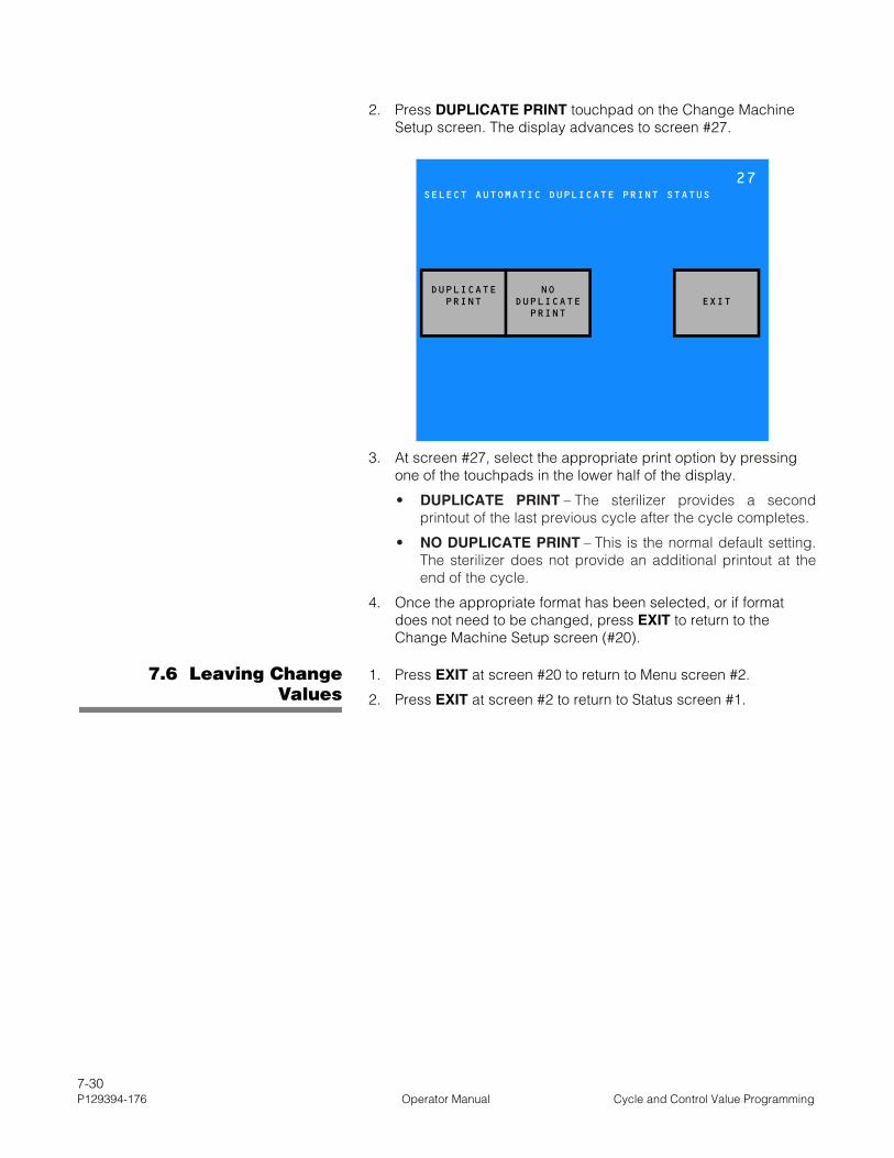
2. Press DUPLICATE PRINT touchpad on the Change Machine Setup screen. The display advances to screen #27.
3. At screen #27, select the appropriate print option by pressing one of the touchpads in the lower half of the display.
• DUPLICATE PRINT – The sterilizer provides a secondprintout of the last previous cycle after the cycle completes.
• NO DUPLICATE PRINT – This is the normal default setting.The sterilizer does not provide an additional printout at theend of the cycle.
4. Once the appropriate format has been selected, or if format does not need to be changed, press EXIT to return to the Change Machine Setup screen (#20).
7.6 Leaving ChangeValues
1. Press EXIT at screen #20 to return to Menu screen #2.
2. Press EXIT at screen #2 to return to Status screen #1.
SELECT AUTOMATIC DUPLICATE PRINT STATUS
27
DUPLICATE PRINT
NO DUPLICATE
PRINTEXIT
7-30P129394-176 Operator Manual Cycle and Control Value Programming

8.1 PreventiveMaintenance Schedule
Maintenance procedures should be performed regularly at theintervals indicated using the maintenance schedule below as aguide. Local conditions (water quality, usage, etc.) may require morefrequent maintenance than indicated.
Important: Follow all safety procedures including Lock out/Tag out.
Inspection Frequency: The AMSCO® C Series Small SteamSterilizer must be inspected twice each year. Operator inspectionsmust be made on a daily or weekly basis as indicated in SECTION 8.2,DAILY MAINTENANCE PROCEDURES and SECTION 8.3, WEEKLY
MAINTENANCE PROCEDURE: FLUSH CHAMBER DRAIN.
WARNING – PERSONAL INJURY HAZARD and/or EQUIPMENT DAMAGE HAZARD: Regularly scheduled preventive maintenance is required for safe and reliable operation of this equipment. Contact your STERIS Service Representative to schedule preventive maintenance.
WARNING – PERSONAL INJURY HAZARD and/or EQUIPMENT DAMAGE HAZARD: The performance of the 510k cleared AMSCO C Series Sterilizer is validated as a system including components defined by STERIS in the Operator Manual and Service Manual for the AMSCO C Series Sterilizer. Substitution of unauthorized components can potentially lead to personal injury, damage or premature failure of the product and result in a unit configuration that is inconsistent with the validated, FDA cleared product. STERIS' warranty is void if components are used that are not approved. DO NOT USE components that are not validated as part of the AMSCO C Series Sterilizer.
�
�
Table 8-1. Preventive MaintenancePeriodic Maintenance Schedule for AMSCO C Series Small Steam Sterilizer
Service RequiredMinimum Inspection
Frequency
1.0 Administrative 2 x per year (4 x w/generator)
1.1 Discuss equipment operation with operator.
2.0 Restorative – Rebuilds and replacements 1 x per year unless noted
2.1 Rebuild steam manifold
2.2 Rebuild water manifold
2.3 Rebuild Jacket Trap
2.4 Replace safety valve
2.5 Replace air filter
2.6 Rebuild Pressure Regulator (PRV)
2.7 Replace jacket trap check valve (CK3)
2.8 Rebuild exhaust manifold
2.9 Replace check valve (CK14)
STEAM GENERATOR (If applicable)
ROUTINE MAINTENANCE
Routine Maintenance Operator Manual P
8
8-1129394-176
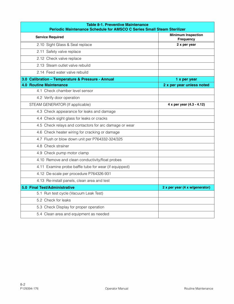
2.10 Sight Glass & Seal replace 2 x per year
2.11 Safety valve replace
2.12 Check valve replace
2.13 Steam outlet valve rebuild
2.14 Feed water valve rebuild
3.0 Calibration – Temperature & Pressure - Annual 1 x per year
4.0 Routine Maintenance 2 x per year unless noted
4.1 Check chamber level sensor
4.2 Verify door operation
STEAM GENERATOR (If applicable) 4 x per year (4.3 - 4.12)
4.3 Check appearance for leaks and damage
4.4 Check sight glass for leaks or cracks
4.5 Check relays and contactors for arc damage or wear
4.6 Check heater wiring for cracking or damage
4.7 Flush or blow down unit per P764332-324/325
4.8 Check strainer
4.9 Check pump motor clamp
4.10 Remove and clean conductivity/float probes
4.11 Examine probe baffle tube for wear (if equipped)
4.12 De-scale per procedure P764326-931
4.13 Re-install panels, clean area and test
5.0 Final Test/Administrative 2 x per year (4 x w/generator)
5.1 Run test cycle (Vacuum Leak Test)
5.2 Check for leaks
5.3 Check Display for proper operation
5.4 Clean area and equipment as needed
Table 8-1. Preventive MaintenancePeriodic Maintenance Schedule for AMSCO C Series Small Steam Sterilizer
Service RequiredMinimum Inspection
Frequency
8-2P129394-176 Operator Manual Routine Maintenance
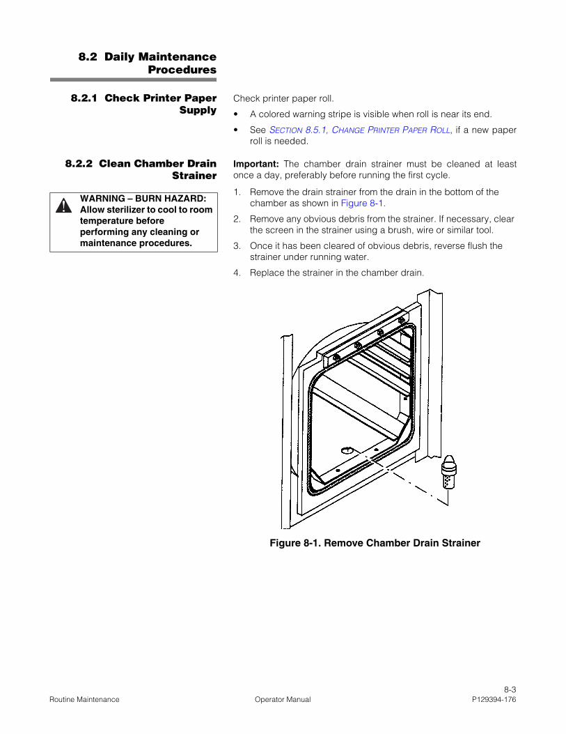
8.2 Daily MaintenanceProcedures
8.2.1 Check Printer PaperSupply
Check printer paper roll.
• A colored warning stripe is visible when roll is near its end.
• See SECTION 8.5.1, CHANGE PRINTER PAPER ROLL, if a new paperroll is needed.
8.2.2 Clean Chamber DrainStrainer
Important: The chamber drain strainer must be cleaned at leastonce a day, preferably before running the first cycle.
1. Remove the drain strainer from the drain in the bottom of the chamber as shown in Figure 8-1.
2. Remove any obvious debris from the strainer. If necessary, clear the screen in the strainer using a brush, wire or similar tool.
3. Once it has been cleared of obvious debris, reverse flush the strainer under running water.
4. Replace the strainer in the chamber drain.
Figure 8-1. Remove Chamber Drain Strainer
WARNING – BURN HAZARD: Allow sterilizer to cool to room temperature before performing any cleaning or maintenance procedures.
�
8-3Routine Maintenance Operator Manual P129394-176

8.3 WeeklyMaintenance
Procedure: FlushChamber Drain
Flush chamber drain as follows whenever the line becomes clogged:
1. Turn off steam supply valve. Wait until jacket pressure is zero. Wait until chamber has cooled to room temperature.
2. Remove chamber drain strainer (Figure 8-1). Clean strainer using procedures given SECTION 8.2.2, if necessary.
3. Pour a solution of 60 mL (1/4 cup) of Liqui-Jet 2 Instrument Detergent (Contact your local STERIS representative), and 500 mL (1 pint) of hot water into the drain. Solution may puddle in the bottom of the chamber.
Should the detergents in Step 3 be unavailable, you may use a hot solution of 15mL (1 tablespoon) of trisodium phosphate to 500 mL (1 pint) of hot water.
4. Open door and place strainer back in drain.
WARNING – BURN HAZARD: Allow sterilizer and accessories to cool to room temperature before performing any cleaning or maintenance procedures.
�
8-4P129394-176 Operator Manual Routine Maintenance

8.4 Chamber Cleaning Due to differences in water quality, steam quality, frequency of useand boiler additives, no specific frequency interval is recommendedfor chamber cleaning. Operators must determine appropriatecleaning interval based on the local water conditions and chamberappearance.
Chamber cleaning should be performed:
• When spills or other soiling have occurred in the chamber
• Periodically to maintain sterilizer cleanliness and appearance
• When processing materials that may be detrimental to thesterilizer (e.g., chloride-containing substances)
1. If applicable, the shelf assembly must be removed before cleaning the chamber.
Single Door a. Remove shelves from rack.
b. Use an 1/8" hex wrench to loosen (but not remove) the set screws at the front of the rack assembly.
c. Remove the rack assembly from the chamber.
Double Door a. Remove shelves from rack.
b. Use an 1/8" hex wrench to loosen (but not remove) the set screws at each end of the rack assembly.
c. Remove the rack assembly from the chamber.
Important: Chamber must be at room temperature, sterilizer off forapproximately 12 hours, before washing. Open the chamberemergency manual exhaust valve. See Figure 5-11 (page 5-15) forvalve location.
WARNING – SLIPPING HAZARD: To prevent falls, keep floors dry by immediately wiping up any spilled liquids or condensation in sterilizer loading and unloading areas.
WARNING – BURN HAZARD: Allow sterilizer to cool to room temperature before performing any cleaning or maintenance procedures.
�
�
8-5Routine Maintenance Operator Manual P129394-176

2. Wash the inside of the chamber and shelf assembly (plus any other loading equipment) with a mild detergent solution such as Liquid-Jet 2 Instrument Detergent or current equivalent product. (Contact STERIS.)
3. Once the chamber is clean, replace the shelf assembly using the reverse of the appropriate procedure given in Step 1. Close the chamber emergency manual exhaust valve.
4. Professional cleaning of the chamber on a yearly basis (or as local conditions require) is suggested to maintain appearance of the chamber interior. Contact STERIS for information regarding this service.
CAUTION – POSSIBLE EQUIPMENT DAMAGE:
• Lifting the chamber float switch when cleaning the chamber may cause the sterilizer control to initiate a “Chamber Flooded” alarm. If this alarm condition occurs, the operator must turn the control power OFF then ON to clear the alarm. The control power switch is located in the mechanical area at the side of the sterilizer. Placing the sterilizer in standby does not clear this alarm.
• Never use a wire brush, abrasives, or steel wool on door and chamber assembly. Do not use cleaners containing chloride on stainless-steel surfaces. Chloride-based cleaners will deteriorate stainless steel, eventually leading to failure of the vessel.
�
8-6P129394-176 Operator Manual Routine Maintenance
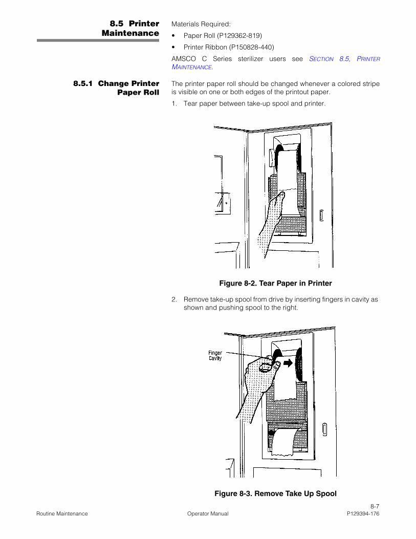
8.5 PrinterMaintenance
Materials Required:
• Paper Roll (P129362-819)
• Printer Ribbon (P150828-440)
AMSCO C Series sterilizer users see SECTION 8.5, PRINTER
MAINTENANCE.
8.5.1 Change PrinterPaper Roll
The printer paper roll should be changed whenever a colored stripeis visible on one or both edges of the printout paper.
1. Tear paper between take-up spool and printer.
2. Remove take-up spool from drive by inserting fingers in cavity as shown and pushing spool to the right.
Figure 8-2. Tear Paper in Printer
Figure 8-3. Remove Take Up Spool
8-7Routine Maintenance Operator Manual P129394-176

3. Pull off right end of spool and remove used paper roll from spindle.
4. Open access door and remove previous paper roll, gently pulling any remaining paper up and out of printer.
Figure 8-4. Remove Paper From Spool
Figure 8-5. Remove Remaining Previous Paper
8-8P129394-176 Operator Manual Routine Maintenance
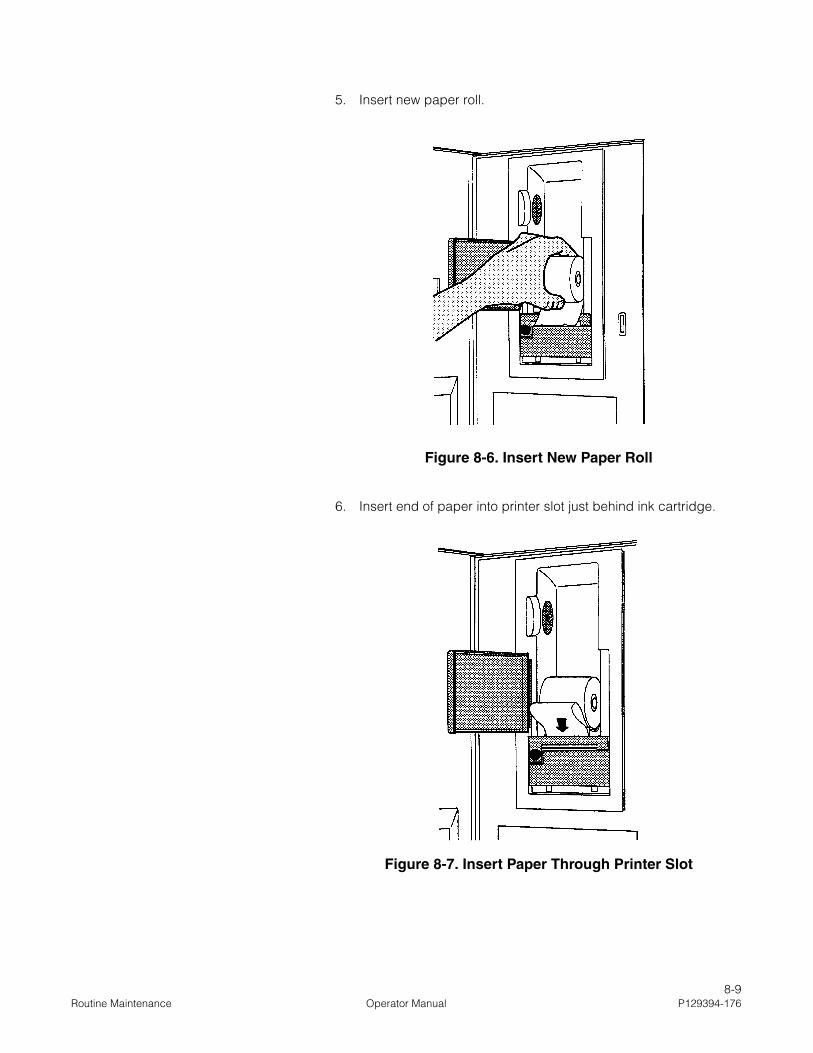
5. Insert new paper roll.
6. Insert end of paper into printer slot just behind ink cartridge.
Figure 8-6. Insert New Paper Roll
Figure 8-7. Insert Paper Through Printer Slot
8-9Routine Maintenance Operator Manual P129394-176

7. Press PAPER FEED touch-screen pad on display until paper advances through printer and ink cartridge, exiting the front.
Figure 8-8. Press Paper Feed Touch Screen Button
8-10P129394-176 Operator Manual Routine Maintenance
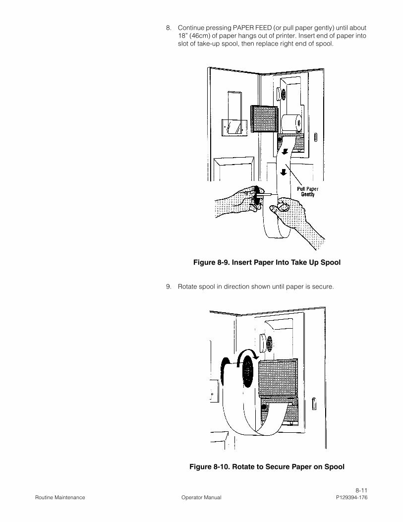
8. Continue pressing PAPER FEED (or pull paper gently) until about 18” (46cm) of paper hangs out of printer. Insert end of paper into slot of take-up spool, then replace right end of spool.
9. Rotate spool in direction shown until paper is secure.
Figure 8-9. Insert Paper Into Take Up Spool
Figure 8-10. Rotate to Secure Paper on Spool
8-11Routine Maintenance Operator Manual P129394-176

10. Reinstall take-up spool on magnetic idler. Manually roll up slack paper.
8.5.2 Change Printer InkCartridge
The printer ink cartridge should be changed as soon as the type onprintouts is light or faded, and before printouts become difficult toread.
1. Tear paper between take-up spool and printer.
Figure 8-11. Reinstall Take Up Spool
Figure 8-12. Tear Paper
8-12P129394-176 Operator Manual Routine Maintenance

2. Open access door, then press on right end of ink cartridge, until left end of cartridge pops out of the printer.
3. Slip cartridge off end of paper. Slip new cartridge over paper in the same way as before, making sure paper slides between ink cartridge housing and ink ribbon.
Figure 8-13. Press On End of Cartridge
Figure 8-14. Remove Cartridge
8-13Routine Maintenance Operator Manual P129394-176
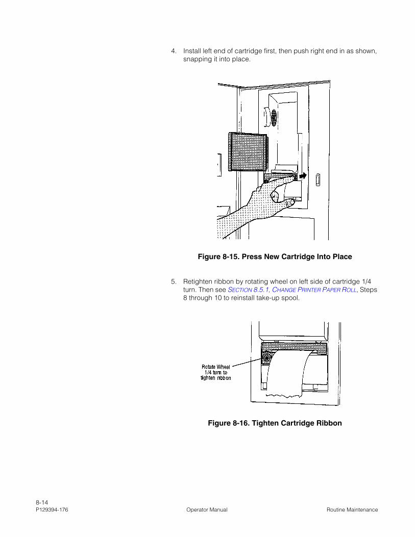
4. Install left end of cartridge first, then push right end in as shown, snapping it into place.
5. Retighten ribbon by rotating wheel on left side of cartridge 1/4 turn. Then see SECTION 8.5.1, CHANGE PRINTER PAPER ROLL, Steps 8 through 10 to reinstall take-up spool.
Figure 8-15. Press New Cartridge Into Place
Figure 8-16. Tighten Cartridge Ribbon
8-14P129394-176 Operator Manual Routine Maintenance
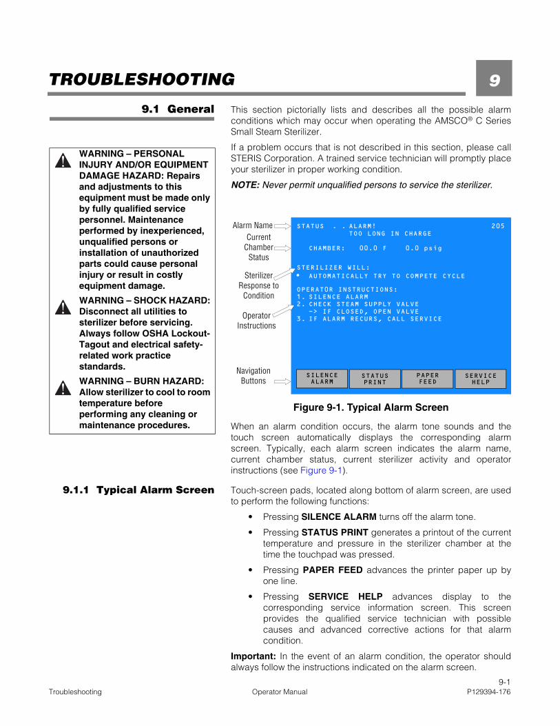
9-1
9.1 General This section pictorially lists and describes all the possible alarmconditions which may occur when operating the AMSCO® C SeriesSmall Steam Sterilizer.
If a problem occurs that is not described in this section, please callSTERIS Corporation. A trained service technician will promptly placeyour sterilizer in proper working condition.
NOTE: Never permit unqualified persons to service the sterilizer.
Figure 9-1. Typical Alarm Screen
When an alarm condition occurs, the alarm tone sounds and thetouch screen automatically displays the corresponding alarmscreen. Typically, each alarm screen indicates the alarm name,current chamber status, current sterilizer activity and operatorinstructions (see Figure 9-1).
9.1.1 Typical Alarm Screen Touch-screen pads, located along bottom of alarm screen, are usedto perform the following functions:
• Pressing SILENCE ALARM turns off the alarm tone.
• Pressing STATUS PRINT generates a printout of the currenttemperature and pressure in the sterilizer chamber at thetime the touchpad was pressed.
• Pressing PAPER FEED advances the printer paper up byone line.
• Pressing SERVICE HELP advances display to thecorresponding service information screen. This screenprovides the qualified service technician with possiblecauses and advanced corrective actions for that alarmcondition.
Important: In the event of an alarm condition, the operator shouldalways follow the instructions indicated on the alarm screen.
WARNING – PERSONAL INJURY AND/OR EQUIPMENT DAMAGE HAZARD: Repairs and adjustments to this equipment must be made only by fully qualified service personnel. Maintenance performed by inexperienced, unqualified persons or installation of unauthorized parts could cause personal injury or result in costly equipment damage.
WARNING – SHOCK HAZARD: Disconnect all utilities to sterilizer before servicing. Always follow OSHA Lockout-Tagout and electrical safety-related work practice standards.
WARNING – BURN HAZARD: Allow sterilizer to cool to room temperature before performing any cleaning or maintenance procedures.
�
�
�
STATUS . . ALARM! 205TOO LONG IN CHARGE
CHAMBER: 00.0 F 0.0 psig
STERILIZER WILL:• AUTOMATICALLY TRY TO COMPETE CYCLE
OPERAT0R INSTRUCTIONS:1. SILENCE ALARM2. CHECK STEAM SUPPLY VALVE
-> IF CLOSED, OPEN VALVE3. IF ALARM RECURS, CALL SERVICE
SERVICEHELP
STATUSPRINT
SILENCEALARM
PAPERFEED
Alarm NameCurrent
Chamber Status
Sterilizer Response to
Condition
Operator Instructions
NavigationButtons
TROUBLESHOOTING
Troubleshooting Operator Manual P
9
129394-176
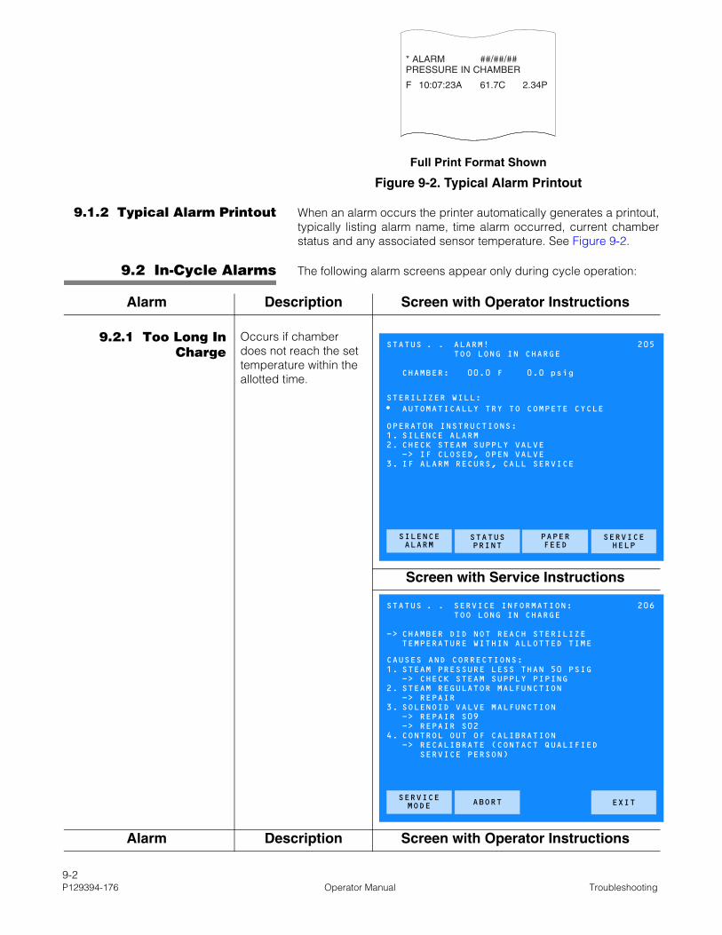
Full Print Format Shown
Figure 9-2. Typical Alarm Printout
9.1.2 Typical Alarm Printout When an alarm occurs the printer automatically generates a printout,typically listing alarm name, time alarm occurred, current chamberstatus and any associated sensor temperature. See Figure 9-2.
9.2 In-Cycle Alarms The following alarm screens appear only during cycle operation:
* ALARM ##/##/##PRESSURE IN CHAMBER
F 10:07:23A 61.7C 2.34P
Alarm Description Screen with Operator Instructions
9.2.1 Too Long InCharge
Occurs if chamber does not reach the set temperature within the allotted time.
Screen with Service Instructions
Alarm Description Screen with Operator Instructions
STATUS . . ALARM! 205TOO LONG IN CHARGE
CHAMBER: 00.0 F 0.0 psig
STERILIZER WILL:
• AUTOMATICALLY TRY TO COMPETE CYCLE
OPERAT0R INSTRUCTIONS:1. SILENCE ALARM2. CHECK STEAM SUPPLY VALVE
-> IF CLOSED, OPEN VALVE3. IF ALARM RECURS, CALL SERVICE
SERVICEHELP
STATUSPRINT
SILENCEALARM
PAPERFEED
STATUS . . SERVICE INFORMATION: 206TOO LONG IN CHARGE
-> CHAMBER DID NOT REACH STERILIZE TEMPERATURE WITHIN ALLOTTED TIME
CAUSES AND CORRECTIONS:1. STEAM PRESSURE LESS THAN 50 PSIG
-> CHECK STEAM SUPPLY PIPING2. STEAM REGULATOR MALFUNCTION
-> REPAIR3. SOLENOID VALVE MALFUNCTION
-> REPAIR S09-> REPAIR S02
4. CONTROL OUT OF CALIBRATION-> RECALIBRATE (CONTACT QUALIFIED SERVICE PERSON)
EXITABORTSERVICEMODE
9-2P129394-176 Operator Manual Troubleshooting
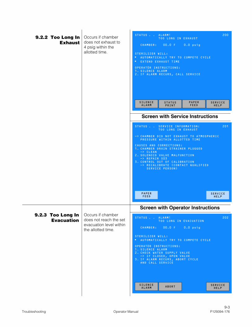
9.2.2 Too Long InExhaust
Occurs if chamber does not exhaust to 4 psig within the allotted time.
Screen with Service Instructions
Screen with Operator Instructions9.2.3 Too Long In
EvacuationOccurs if chamber does not reach the set evacuation level within the allotted time.
STATUS . . ALARM! 200TOO LONG IN EXHAUST
CHAMBER: 00.0 F 0.0 psig
STERILIZER WILL:
• AUTOMATICALLY TRY TO COMPETE CYCLE
• EXTEND EXHAUST TIME
OPERAT0R INSTRUCTIONS:1. SILENCE ALARM2. IF ALARM RECURS, CALL SERVICE
SERVICEHELP
STATUSPRINT
SILENCEALARM
PAPERFEED
STATUS . . SERVICE INFORMATION: 201TOO LONG IN EXHAUST
-> CHAMBER DID NOT EXHAUST TO ATMOSPHERIC PRESSURE WITHIN ALLOTTED TIME
CAUSES AND CORRECTIONS:1. CHAMBER DRAIN STRAINER PLUGGED
-> CLEAN2. SOLENOID VALVE MALFUNCTION
-> REPAIR S033. CONTROL OUT OF CALIBRATION
-> RECALIBRATE (CONTACT QUALIFIED SERVICE PERSON)
PAPERFEED
SERVICEHELP
STATUS . . ALARM! 202TOO LONG IN EVACUATION
CHAMBER: 00.0 F 0.0 psig
STERILIZER WILL:
• AUTOMATICALLY TRY TO COMPETE CYCLE
OPERAT0R INSTRUCTIONS:1. SILENCE ALARM2. CHECK WATER SUPPLY VALVE
-> IF CLOSED, OPEN VALVE3. IF ALARM RECURS, ABORT CYCLE
AND CALL SERVICE
SERVICEHELPABORT
SILENCEALARM
9-3Troubleshooting Operator Manual P129394-176

Alarm Description Screen with Service Instructions
Too Long In Evacuation(Continued)
NOTE: This alarm has two service help screens.
Screen with Operator Instructions9.2.4 Too Long In Air
BreakOccurs if chamber does not air break the vacuum to 2 inHg within the allotted time.
STATUS . . SERVICE INFORMATION: 203TOO LONG IN EVACUATION
-> CHAMBER DID NOT REACH REQUIRED VACUUM LEVEL WITHIN ALLOTTED TIME
CAUSES AND CORRECTIONS:1. WATER PRESSURE LESS THAN 30 PSIG
-> CHECK WATER SUPPLY PIPING2. CHAMBER DRAIN STRAINER PLUGGED
-> CLEAN3. CHECK VALVE MALFUNCTION
-> REPAIR4. SOLENOID VALVE MALFUNCTION
-> REPAIR5. DOOR SEAL NOT ACTIVATED
-> CHECK SEAL -> CHECK SEAL STEAM AND EXHAUST
MOREHELP
STATUSPRINT
PAPERFEED
EXIT
STATUS . . SERVICE INFORMATION: 204TOO LONG IN EVACUATION
-> CHAMBER DID NOT REACH REQUIRED VACUUM LEVEL WITHIN ALLOTTED TIME
CAUSES AND CORRECTIONS:1. LEAK IN PLUMBING
-> REPAIR-> RUN A LEAK TEST
2. CONTROL OUT OF CALIBRATION-> RECALIBRATE (CONTACT QUALIFIED SERVICE PERSON)
EXITPAPERFEED ABORT
STATUS . . ALARM! 225TOO LONG IN AIR BREAK
CHAMBER: 00.0 F 0.0 psig
STERILIZER WILL:
• AUTOMATICALLY TRY TO COMPLETE CYCLE
• EXTEND EXHAUST TIME
OPERAT0R INSTRUCTIONS:1. SILENCE ALARM2. IF ALARM RECURS, CALL SERVICE
SERVICEHELP
STATUSPRINT
SILENCEALARM
PAPERFEED
9-4P129394-176 Operator Manual Troubleshooting

Alarm Description Screen with Service Instructions
Too Long In Air Break(Continued)
Screen with Operator Instructions9.2.5 Under Sterilize
TemperatureOccurs if chamber temperature drops below sterilize temperature.
Screen with Service Instructions
STATUS . . SERVICE INFORMATION: 226TOO LONG IN AIR BREAK
-> CHAMBER DID NOT AIR BREAK VACUUM TO 1 PSIG WITHIN ALLOTTED TIME
CAUSES AND CORRECTIONS:1. AIR INLET FILTER PLUGGED
-> REPAIR2. SOLENOID VALVE MALFUNCTION
-> REPAIR S013. CONTROL OUT OF CALIBRATION
-> RECALIBRATE (CONTACT QUALIFIED SERVICE PERSON)
EXITPAPERFEED
STATUS . . ALARM! 223UNDER STERILIZE TEMPERATURE
CHAMBER: 00.0 F 0.0 psig
STERILIZER WILL:• AUTOMATICALLY RESTART STERILIZE TIME
AND CONTINUE CYCLE AFTER SET TEMP. IS REACHED
OPERAT0R INSTRUCTIONS:1. SILENCE ALARM2. IF ALARM RECURS, CALL SERVICE
SERVICEHELP
STATUSPRINT
SILENCEALARM
PAPERFEED
STATUS . . SERVICE INFORMATION: 224UNDER STERILIZE TEMPERATURE
-> CHAMBER TEMPERATURE DROPPED BELOW STERILIZE TEMPERATURE BY UNDERTEMP TEMPERATURE VALUE
CAUSES AND CORRECTIONS:1. STEAM PRESSURE LESS THAN 50 PSIG
-> CHECK STEAM SUPPLY PIPING2. CHAMBER STEAM TRAP MALFUNCTION
-> REPAIR3. SOLENOID VALVE MALFUNCTION
-> REPAIR S09-> REPAIR S02
4. CONTROL OUT OF CALIBRATION-> RECALIBRATE (CONTACT QUALIFIED SERVICE PERSON)
EXITPAPERFEED
9-5Troubleshooting Operator Manual P129394-176
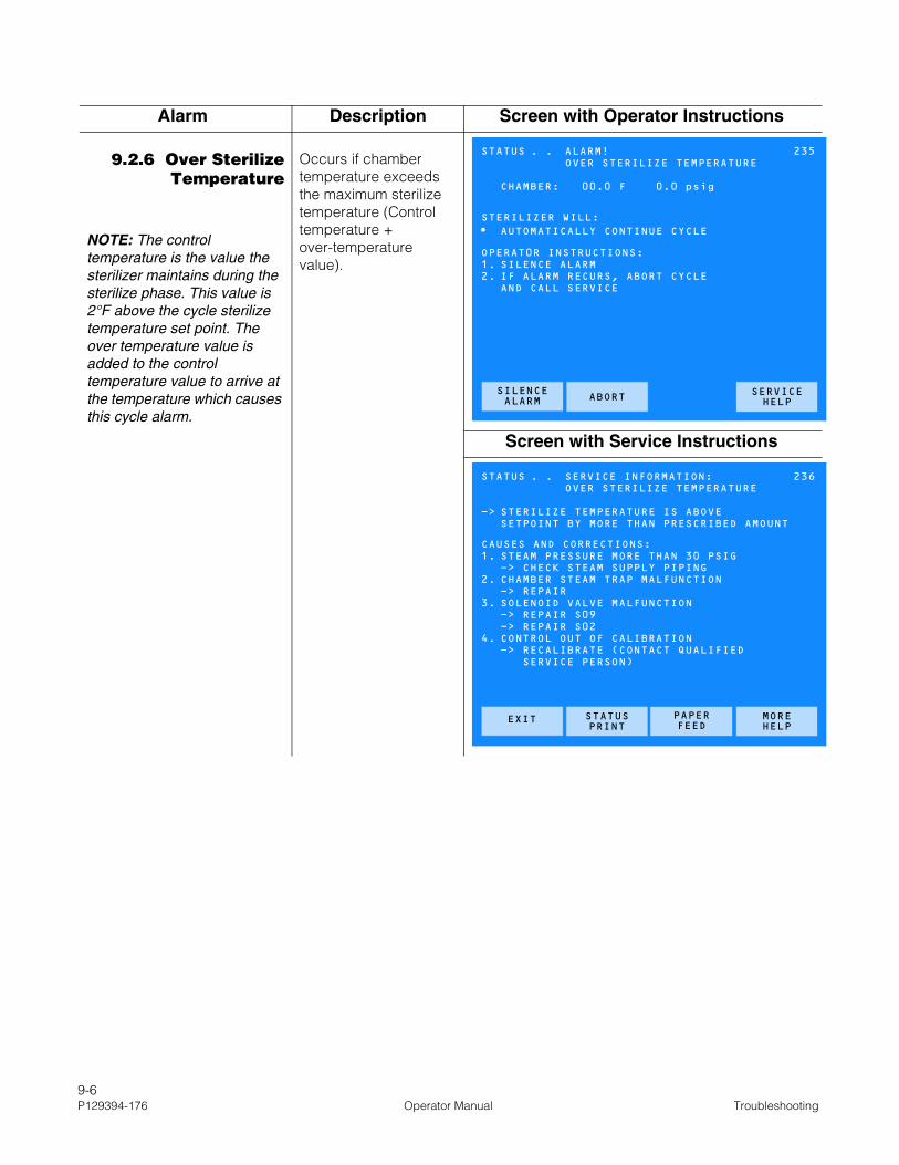
Alarm Description Screen with Operator Instructions
9.2.6 Over SterilizeTemperature
NOTE: The control temperature is the value the sterilizer maintains during the sterilize phase. This value is 2°F above the cycle sterilize temperature set point. The over temperature value is added to the control temperature value to arrive at the temperature which causes this cycle alarm.
Occurs if chamber temperature exceeds the maximum sterilize temperature (Control temperature + over-temperature value).
Screen with Service Instructions
STATUS . . ALARM! 235OVER STERILIZE TEMPERATURE
CHAMBER: 00.0 F 0.0 psig
STERILIZER WILL:
• AUTOMATICALLY CONTINUE CYCLE
OPERAT0R INSTRUCTIONS:1. SILENCE ALARM2. IF ALARM RECURS, ABORT CYCLE
AND CALL SERVICE
SERVICEHELPABORT
SILENCEALARM
STATUS . . SERVICE INFORMATION: 236OVER STERILIZE TEMPERATURE
-> STERILIZE TEMPERATURE IS ABOVE SETPOINT BY MORE THAN PRESCRIBED AMOUNT
CAUSES AND CORRECTIONS:1. STEAM PRESSURE MORE THAN 30 PSIG
-> CHECK STEAM SUPPLY PIPING2. CHAMBER STEAM TRAP MALFUNCTION
-> REPAIR3. SOLENOID VALVE MALFUNCTION
-> REPAIR S09-> REPAIR S02
4. CONTROL OUT OF CALIBRATION-> RECALIBRATE (CONTACT QUALIFIED SERVICE PERSON)
MOREHELP
STATUSPRINT
PAPERFEED
EXIT
9-6P129394-176 Operator Manual Troubleshooting

Alarm Description Screen with Operator Instructions
9.2.7 Door Unsealed Occurs if steam pressure in door seal drops below 5 psig.
Screen with Service Instructions
Screen with Operator Instructions9.2.8 Chamber
Pressure/TemperatureFailure
Occurs if chamber pressure or temperature readings are outside the normal steam range during sterilize phase.
STATUS . . ALARM! 207DOOR UNSEALED
CHAMBER: 00.0 F 0.0 psig
STERILIZER WILL:• AUTOMATICALLY ABORT CYCLE
• EXHAUST OR AIR BREAK CHAMBER TO ATMOSPHERIC PRESSURE
OPERAT0R INSTRUCTIONS:1. SILENCE ALARM2. CALL SERVICE
SERVICEHELP
STATUSPRINT
SILENCEALARM
PAPERFEED
STATUS . . SERVICE INFORMATION: 208DOOR UNSEALED
-> STEAM PRESSURE IN DOOR SEAL BELOW10 PSIG
CAUSES AND CORRECTIONS:1. SEAL PRESSURE SWITCH MALFUNCTION
-> CHECK PS1 (PS2) CONNECTIONS-> READJUST PS1 (PS2)-> REPAIR PS1 (PS2)
2. SEAL NOT ACTIVATED-> CHECK SEAL STEAM-> CHECK SEAL EXHAUST
3. SOLENOID VALVE MALFUNCTION-> REPAIR S35 (S36)
PAPERFEED EXIT
CLEARALARM
STATUS . . ALARM! 219PRESSURE/TEMPERATURE FAILURE
CHAMBER: 00.0 F 0.0 psig
STERILIZER WILL:• AUTOMATICALLY ABORT CYCLE
OPERAT0R INSTRUCTIONS:1. SILENCE ALARM2. CALL SERVICE
SERVICEHELP
STATUSPRINT
SILENCEALARM
PAPERFEED
9-7Troubleshooting Operator Manual P129394-176
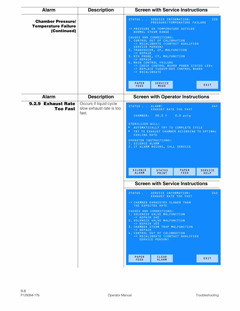
9-8
Alarm Description Screen with Service Instructions
Chamber Pressure/Temperature Failure
(Continued)
Alarm Description Screen with Operator Instructions9.2.9 Exhaust Rate
Too FastOccurs if liquid cycle slow exhaust rate is too fast.
Screen with Service Instructions
STATUS . . SERVICE INFORMATION: 220PRESSURE/TEMPERATURE FAILURE
-> PRESSURE OR TEMPERATURE OUTSIDE NORMAL STEAM RANGE
CAUSES AND CORRECTIONS:1. CONTROL OUT OF CALIBRATION
-> RECALIBRATE (CONTACT QUALIFIEDSERVICE PERSON)
2. TRANSDUCER, CP, MALFUNCTION-> REPAIR
3. RTD PROBE, CT, MALFUNCTION-> REPAIR
4. MAIN CONTROL FAILURE-> CHECK CONTROL BOARD POWER STATUS LEDs-> REPLACE 146659-065 CONTROL BOARD-> RECALIBRATE
PAPERFEED EXIT
SERVICEMODE
STATUS . . ALARM! 241EXHAUST RATE TOO FAST
CHAMBER: 00.0 F 0.0 psig
STERILIZER WILL:
• AUTOMATICALLY TRY TO COMPLETE CYCLE
• TRY TO EXHAUST CHAMBER ACCORDING TO OPTIMAL COOLING RATE
OPERAT0R INSTRUCTIONS:1. SILENCE ALARM2. IF ALARM RECURS, CALL SERVICE
SERVICEHELP
STATUSPRINT
SILENCEALARM
PAPERFEED
STATUS . . SERVICE INFORMATION: 242EXHAUST RATE TOO FAST
-> CHAMBER EXHAUSTED SLOWER THAN THE EXPECTED RATE
CAUSES AND CORRECTIONS:1. SOLENOID VALVE MALFUNCTION
-> REPAIR S402. SOLENOID VALVE MALFUNCTION
-> REPAIR S033. CHAMBER STEAM TRAP MALFUNCTION
-> REPAIR4. CONTROL OUT OF CALIBRATION
-> RECALIBRATE (CONTACT QUALIFIED SERVICE PERSON)
PAPERFEED EXIT
CLEARALARM
P129394-176 Operator Manual Troubleshooting

Alarm Description Screen with Operator Instructions
9.2.10 Exhaust RateToo Slow
Occurs if liquid cycle exhaust rate is too slow.
Screen with Service Instructions
Screen with Operator Instructions
9.2.11 RecorderDeviation Alarm
Occurs if the two temperature sensing elements in the chamber drain probe read more than 1°F (0.5°C) apart.
STATUS . . ALARM! 243EXHAUST RATE TOO SLOW
CHAMBER: 00.0 F 0.0 psig
STERILIZER WILL:• AUTOMATICALLY TRY TO COMPLETE CYCLE
• TRY TO EXHAUST CHAMBER ACCORDING TO OPTIMAL COOLING RATE
OPERAT0R INSTRUCTIONS:1. SILENCE ALARM2. IF ALARM RECURS, CALL SERVICE
SERVICEHELP
STATUSPRINT
SILENCEALARM
PAPERFEED
STATUS . . SERVICE INFORMATION: 244EXHAUST RATE TOO SLOW
-> CHAMBER EXHAUSTED SLOWER THAN THE EXPECTED RATE
CAUSES AND CORRECTIONS:1. SOLENOID VALVE MALFUNCTION
-> REPAIR S402. SOLENOID VALVE MALFUNCTION
-> REPAIR S033. CHAMBER STEAM TRAP MALFUNCTION
-> REPAIR4. CONTROL OUT OF CALIBRATION
-> RECALIBRATE (CONTACT QUALIFIED SERVICE PERSON)
PAPERFEED EXITCLEAR
ALARM
STATUS . . ALARM! 281RECORDER DEVIATION
CHAMBER: 00.0 F 0.0 psigRECORDER: 300.0 F
STERILIZER WILL:• AUTOMATICALLY ABORT CYCLE
OPERAT0R INSTRUCTIONS:1. SILENCE ALARM2. CALL SERVICE
STATUSPRINT
SILENCEALARM
PAPERFEED
9-9Troubleshooting Operator Manual P129394-176
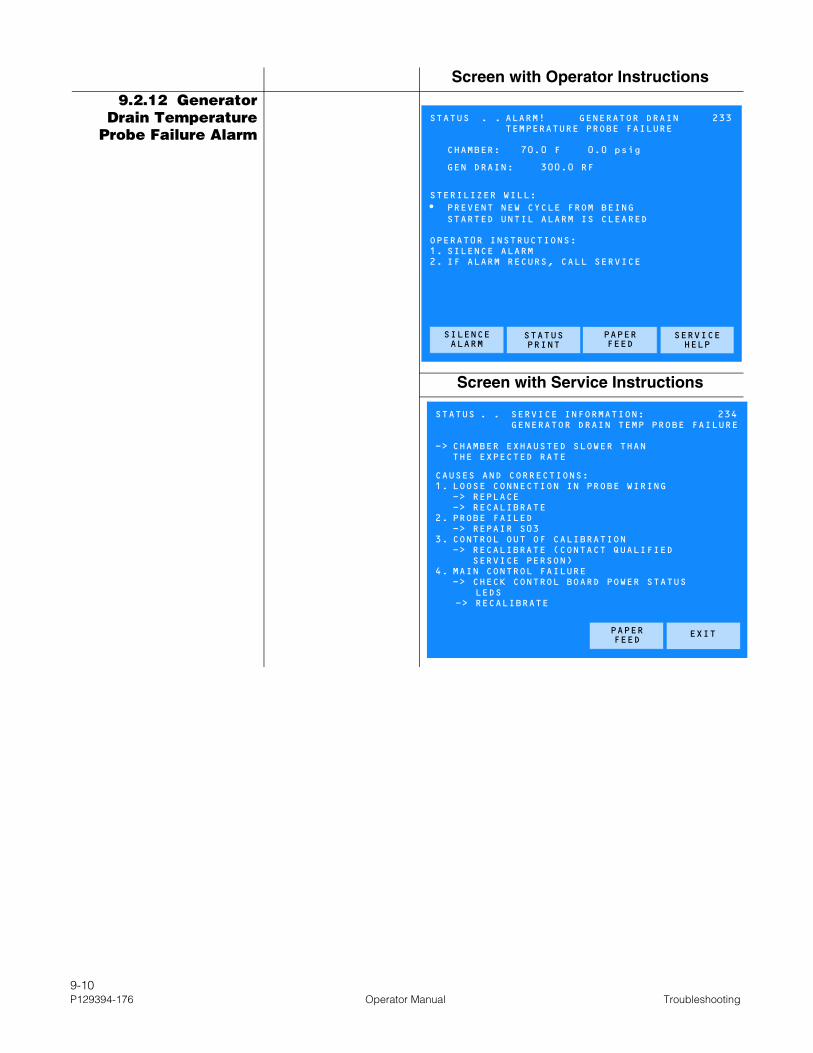
Screen with Operator Instructions9.2.12 Generator
Drain TemperatureProbe Failure Alarm
Screen with Service Instructions
STATUS . . ALARM! GENERATOR DRAIN 233TEMPERATURE PROBE FAILURE
CHAMBER: 70.0 F 0.0 psig
GEN DRAIN: 300.0 RF
STERILIZER WILL:• PREVENT NEW CYCLE FROM BEING
STARTED UNTIL ALARM IS CLEARED
OPERAT0R INSTRUCTIONS:1. SILENCE ALARM2. IF ALARM RECURS, CALL SERVICE
SERVICEHELP
STATUSPRINT
SILENCEALARM
PAPERFEED
STATUS . . SERVICE INFORMATION: 234GENERATOR DRAIN TEMP PROBE FAILURE
-> CHAMBER EXHAUSTED SLOWER THAN THE EXPECTED RATE
CAUSES AND CORRECTIONS:1. LOOSE CONNECTION IN PROBE WIRING
-> REPLACE-> RECALIBRATE
2. PROBE FAILED-> REPAIR S03
3. CONTROL OUT OF CALIBRATION-> RECALIBRATE (CONTACT QUALIFIED SERVICE PERSON)
4. MAIN CONTROL FAILURE -> CHECK CONTROL BOARD POWER STATUS
LEDS -> RECALIBRATE
PAPERFEED
EXIT
9-10P129394-176 Operator Manual Troubleshooting
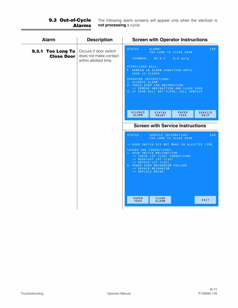
9.3 Out-of-CycleAlarms
The following alarm screens will appear only when the sterilizer isnot processing a cycle.
Alarm Description Screen with Operator Instructions
9.3.1 Too Long ToClose Door
Occurs if door switch does not make contact within allotted time.
Screen with Service Instructions
STATUS . . ALARM! 239TOO LONG TO CLOSE DOOR
CHAMBER: 00.0 F 0.0 psig
STERILIZER WILL:
• REMAIN IN ALARM CONDITION UNTILDOOR IS CLOSED
OPERAT0R INSTRUCTIONS:1. SILENCE ALARM2. CHECK DOOR FOR OBSTRUCTION
-> REMOVE OBSTRUCTION AND CLOSE DOOR3. IF DOOR WILL NOT CLOSE, CALL SERVICE
SERVICEHELP
STATUSPRINT
SILENCEALARM
PAPERFEED
STATUS . . SERVICE INFORMATION: 240TOO LONG TO CLOSE DOOR
-> DOOR SWITCH DID NOT MAKE IN ALLOTTED TIME
CAUSES AND CORRECTIONS:1. DOOR SWITCH MALFUNCTION
-> CHECK LS1 (LS2) CONNECTIONS-> READJUST LS1 (LS2)-> REPAIR LS1 (LS2)
2. POWER DOOR MECHANISM FAILURE-> REPAIR MECHANISM-> REPLACE MOTOR
PAPERFEED EXIT
CLEARALARM
9-11Troubleshooting Operator Manual P129394-176

Alarm Description Screen with Operator Instructions
9.3.2 Too Long ToOpen Door
Occurs if door switch does not open within the allotted time.
Screen with Service Instructions
STATUS . . ALARM! 245TOO LONG TO OPEN DOOR
CHAMBER: 00.0 F 0.0 psig
STERILIZER WILL:• REMAIN IN ALARM CONDITION UNTIL
DOOR IS OPENED
OPERAT0R INSTRUCTIONS:1. SILENCE ALARM2. CALL SERVICE
SERVICEHELP
STATUSPRINT
SILENCEALARM
PAPERFEED
STATUS . . SERVICE INFORMATION: 246TOO LONG TO OPEN DOOR
-> DOOR SWITCH DID NOT OPEN IN ALLOTTED TIME
CAUSES AND CORRECTIONS:1. DOOR SWITCH MALFUNCTION
-> CHECK LS1 (LS2) CONNECTIONS-> READJUST LS1 (LS2)
2. POWER DOOR MECHANISM FAILURE-> REPAIR MECHANISM-> REPLACE MOTOR
PAPERFEED EXIT
CLEARALARM
9-12P129394-176 Operator Manual Troubleshooting

Screen with Operator Instructions9.3.3 Pressure In
ChamberOccurs if 2 psig pressure is sensed in the chamber.
Screen with Service Instructions
Screen with Operator Instructions9.3.4 Waste
Temperature ProbeFailure
Occurs if waste line temperature reading is outside the normal range of 32 - 293°F (0 - 145°C)
STATUS . . ALARM! 221PRESSURE IN CHAMBER
CHAMBER: 00.0 F 0.0 psig
STERILIZER WILL:
• AUTOMATICALLY EXHAUST CHAMBER TO ATMOSPHERIC PRESSURE
OPERAT0R INSTRUCTIONS:1. SILENCE ALARM2. IF ALARM RECURS, CALL SERVICE
SERVICEHELP
STATUSPRINT
SILENCEALARM
PAPERFEED
STATUS . . SERVICE INFORMATION: 222PRESSURE IN CHAMBER
-> 2 PSIG PRESSURE SENSED IN CHAMBER WHEN NOT IN CYCLE
CAUSES AND CORRECTIONS:1. SOLENOID VALVE MALFUNCTION
-> REPAIR S022. CONTROL OUT OF CALIBRATION
-> RECALIBRATE (CONTACT QUALIFIED SERVICE PERSON)
3. TRANSDUCER, CP, MALFUNCTION-> REPAIR-> RECALIBRATE
4. MAIN CONTROL FAILURE-> CHECK CONTROL BOARD POWER STATUS LEDs-> REPLACE CONTROL BOARD-> RECALIBRATE
PAPERFEED EXIT
STATUS . . ALARM! 215WASTE TEMPERATURE PROBE FAILURE
CHAMBER: 00.0 F 0.0 psigWASTE: 00.0 F
STERILIZER WILL:
• PREVENT NEW CYCLE FROM BEING STARTED UNTIL ALARM IS CLEARED
OPERAT0R INSTRUCTIONS:1. SILENCE ALARM2. CALL SERVICE
SERVICEHELP
STATUSPRINT
SILENCEALARM
PAPERFEED
9-13Troubleshooting Operator Manual P129394-176
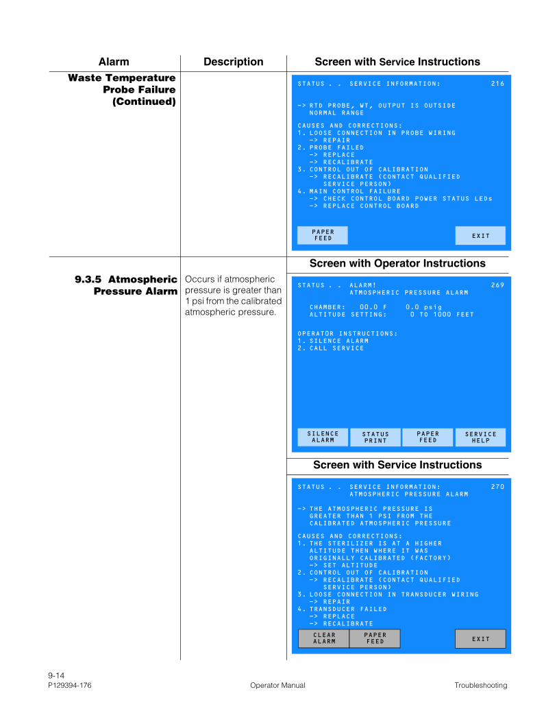
Alarm Description Screen with Service InstructionsWaste Temperature
Probe Failure(Continued)
Screen with Operator Instructions9.3.5 Atmospheric
Pressure AlarmOccurs if atmospheric pressure is greater than 1 psi from the calibrated atmospheric pressure.
Screen with Service Instructions
STATUS . . SERVICE INFORMATION: 216
-> RTD PROBE, WT, OUTPUT IS OUTSIDE NORMAL RANGE
CAUSES AND CORRECTIONS:1. LOOSE CONNECTION IN PROBE WIRING
-> REPAIR2. PROBE FAILED
-> REPLACE-> RECALIBRATE
3. CONTROL OUT OF CALIBRATION-> RECALIBRATE (CONTACT QUALIFIED SERVICE PERSON)
4. MAIN CONTROL FAILURE-> CHECK CONTROL BOARD POWER STATUS LEDs-> REPLACE CONTROL BOARD
PAPERFEED EXIT
STATUS . . ALARM! 269ATMOSPHERIC PRESSURE ALARM
CHAMBER: 00.0 F 0.0 psigALTITUDE SETTING: 0 TO 1000 FEET
OPERAT0R INSTRUCTIONS:1. SILENCE ALARM2. CALL SERVICE
SERVICEHELP
STATUSPRINT
SILENCEALARM
PAPERFEED
STATUS . . SERVICE INFORMATION: 270ATMOSPHERIC PRESSURE ALARM
-> THE ATMOSPHERIC PRESSURE IS GREATER THAN 1 PSI FROM THECALIBRATED ATMOSPHERIC PRESSURE
CAUSES AND CORRECTIONS:1. THE STERILIZER IS AT A HIGHER
ALTITUDE THEN WHERE IT WASORIGINALLY CALIBRATED (FACTORY)-> SET ALTITUDE
2. CONTROL OUT OF CALIBRATION-> RECALIBRATE (CONTACT QUALIFIED SERVICE PERSON)
3. LOOSE CONNECTION IN TRANSDUCER WIRING-> REPAIR
4. TRANSDUCER FAILED-> REPLACE-> RECALIBRATE
PAPERFEED EXIT
CLEARALARM
9-14P129394-176 Operator Manual Troubleshooting

Alarm Description Screen with Operator Instructions9.3.6 Input/Output
Board #1Communication
Failure
The I/O board fails to achieve communication with board #1, #2 or #3 in the control box.
Screen with Service Instructions
Screen with Service Instructions
STATUS . . ALARM! 258INPUT/OUTPUT BOARD #1COMMUNICATION FAILURE
CHAMBER: 00.0 F 0.0 psigLOAD: 000.0 C
STERILIZER WILL:
• AUTOMATICALLY ABORT CYCLE
OPERAT0R INSTRUCTIONS:1. SILENCE ALARM2. CALL SERVICE
STATUSPRINT
SILENCEALARM
PAPERFEED
SERVICEHELP
STATUS . . SERVICE INFORMATION: 260I/O COMMUNICATION FAILURE
-> THE CONTROL BOARD FAILS TOCOMMUNICATE TO BOARD #1, #2 OR #3IN CONTROL BOX.
CAUSES AND CORRECTIONS:1. LOOSE CONNECTION BETWEEN BOARD #1,
#2, #3 AND CONNECTION BOARD-> RESEAT BOARD
2. LOOSE CONNECTIONS BETWEEN CONTROLBOARD AND CONNECTION BOARD-> RESEAT A BOARD
3. BOARD #1, #2 OR #3 DIP SWITCHES CONFIGURED INCORRECTLY-> REFER TO THE SERVICE MANUAL FORINFORMATION ON DIP SWITCHSETTINGS OR CALL SERVICE
4. BOARD #1, #2 OR #3 OR FAIL-> REPLACE
5. FAULTY CONNECTION IN CONTROL BOX-> REPLACE CONTROL BOX
PAPERFEED EXIT
STATUS . . SERVICE INFORMATION: 261INPUT/OUTPUT BOARD #1 FAILURE
-> SWITCHED NEUTRAL RELAY CIRCUITFAILED OPERATIONAL CONTACT TEST.
CAUSES AND CORRECTIONS:1. WET S02, S35 OR S36 SOLENOID VALVE
CONNECTOR-> DRY AND REPAIR CONNECTOR
2. SHORTED MACHINE WIRING CABLE-> REPLACE CABLE
3. FAILED I/O BOARD -> REPLACE I/O BOARD
4. FAILED BACKPLANE OR CONTROL WIRING-> REPLACE BACKPLANE OR CONTROL WIRING
NOTE:REFER TO SERVICE ERRORS #113 - #118AND BOARDS #1 LED D1 TO D3
EXITPAPERFEED
9-15Troubleshooting Operator Manual P129394-176
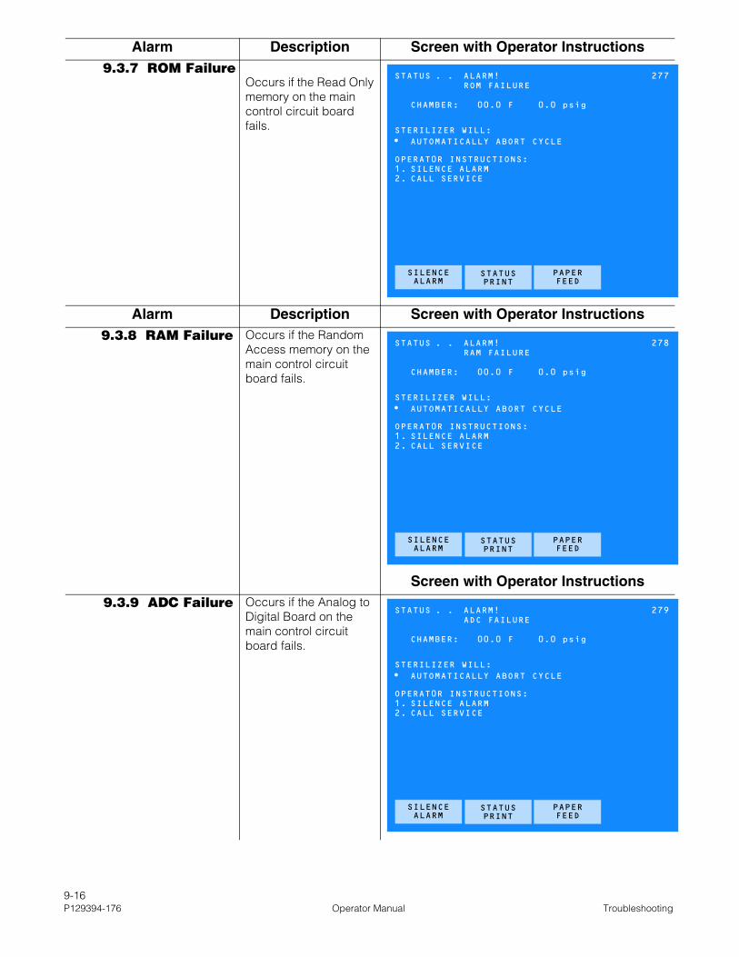
9-16P129394-176 Operator Manual Troubleshooting
Alarm Description Screen with Operator Instructions9.3.7 ROM Failure
Occurs if the Read Only memory on the main control circuit board fails.
Alarm Description Screen with Operator Instructions9.3.8 RAM Failure Occurs if the Random
Access memory on the main control circuit board fails.
Screen with Operator Instructions9.3.9 ADC Failure Occurs if the Analog to
Digital Board on the main control circuit board fails.
STATUS . . ALARM! 277ROM FAILURE
CHAMBER: 00.0 F 0.0 psig
STERILIZER WILL:• AUTOMATICALLY ABORT CYCLE
OPERAT0R INSTRUCTIONS:1. SILENCE ALARM2. CALL SERVICE
STATUSPRINT
SILENCEALARM
PAPERFEED
STATUS . . ALARM! 278RAM FAILURE
CHAMBER: 00.0 F 0.0 psig
STERILIZER WILL:
• AUTOMATICALLY ABORT CYCLE
OPERAT0R INSTRUCTIONS:1. SILENCE ALARM2. CALL SERVICE
STATUSPRINT
SILENCEALARM
PAPERFEED
STATUS . . ALARM! 279ADC FAILURE
CHAMBER: 00.0 F 0.0 psig
STERILIZER WILL:
• AUTOMATICALLY ABORT CYCLE
OPERAT0R INSTRUCTIONS:1. SILENCE ALARM2. CALL SERVICE
STATUSPRINT
SILENCEALARM
PAPERFEED
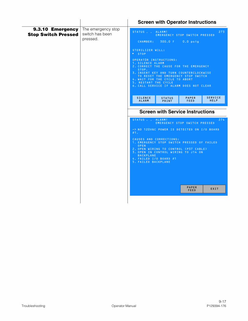
Screen with Operator Instructions9.3.10 Emergency
Stop Switch PressedThe emergency stop switch has been pressed.
Screen with Service Instructions
STATUS . . ALARM! 273EMERGENCY STOP SWITCH PRESSED
CHAMBER: 300.0 F 0.0 psig
STERILIZER WILL:• STOP
OPERAT0R INSTRUCTIONS:1. SILENCE ALARM2. CORRECT THE CAUSE FOR THE EMERGENCY
STOP.3. INSERT KEY AND TURN COUNTERCLOCKWISE
TO RESET THE EMERGENCY STOP SWITCH4. WAIT FOR THE CYCLE TO ABORT5. RESTART THE CYCLE 6. CALL SERVICE IF ALARM DOES NOT CLEAR
STATUSPRINT
SILENCEALARM
PAPERFEED
SERVICEHELP
STATUS . . ALARM! 274. . . . . EMERGENCY STOP SWITCH PRESSED
-> NO 120VQC POWER IS DETECTED ON I/O BOARD #1.
CAUSES AND CORRECTIONS:1. EMERGENCY STOP SWITCH PRESSED OF FAILED
OPEN2. OPEN WIRING TO CONTROL (P37 CABLE) 3. OPEN IN CONTROL WIRING TO J14 ON
BACKPLANE4. FAILED I/O BOARD #15. FAILED BACKPLANE
EXITPAPERFEED
9-17Troubleshooting Operator Manual P129394-176
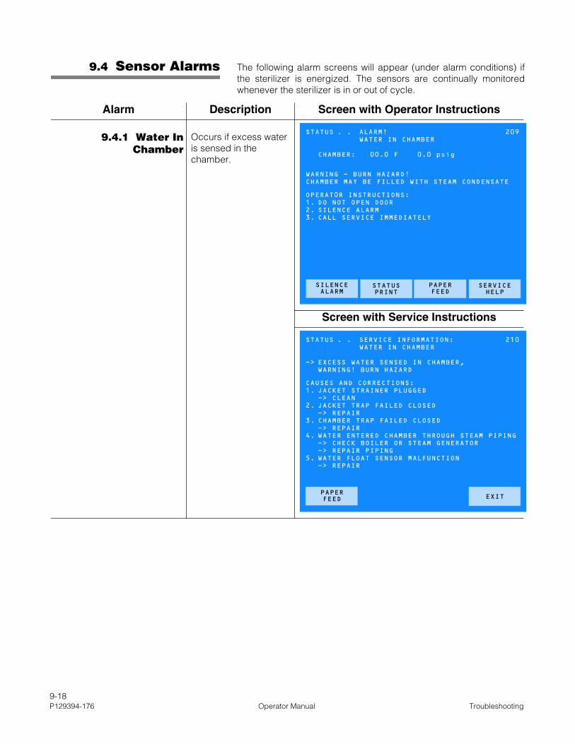
9-18
9.4 Sensor Alarms The following alarm screens will appear (under alarm conditions) ifthe sterilizer is energized. The sensors are continually monitoredwhenever the sterilizer is in or out of cycle.
Alarm Description Screen with Operator Instructions
9.4.1 Water InChamber
Occurs if excess water is sensed in the chamber.
Screen with Service Instructions
STATUS . . ALARM! 209WATER IN CHAMBER
CHAMBER: 00.0 F 0.0 psig
WARNING - BURN HAZARD!CHAMBER MAY BE FILLED WITH STEAM CONDENSATE
OPERAT0R INSTRUCTIONS:1. DO NOT OPEN DOOR2. SILENCE ALARM3. CALL SERVICE IMMEDIATELY
SERVICEHELP
STATUSPRINT
SILENCEALARM
PAPERFEED
STATUS . . SERVICE INFORMATION: 210WATER IN CHAMBER
-> EXCESS WATER SENSED IN CHAMBER, WARNING! BURN HAZARD
CAUSES AND CORRECTIONS:1. JACKET STRAINER PLUGGED
-> CLEAN2. JACKET TRAP FAILED CLOSED
-> REPAIR3. CHAMBER TRAP FAILED CLOSED
-> REPAIR4. WATER ENTERED CHAMBER THROUGH STEAM PIPING
-> CHECK BOILER OR STEAM GENERATOR-> REPAIR PIPING
5. WATER FLOAT SENSOR MALFUNCTION-> REPAIR
PAPERFEED EXIT
P129394-176 Operator Manual Troubleshooting
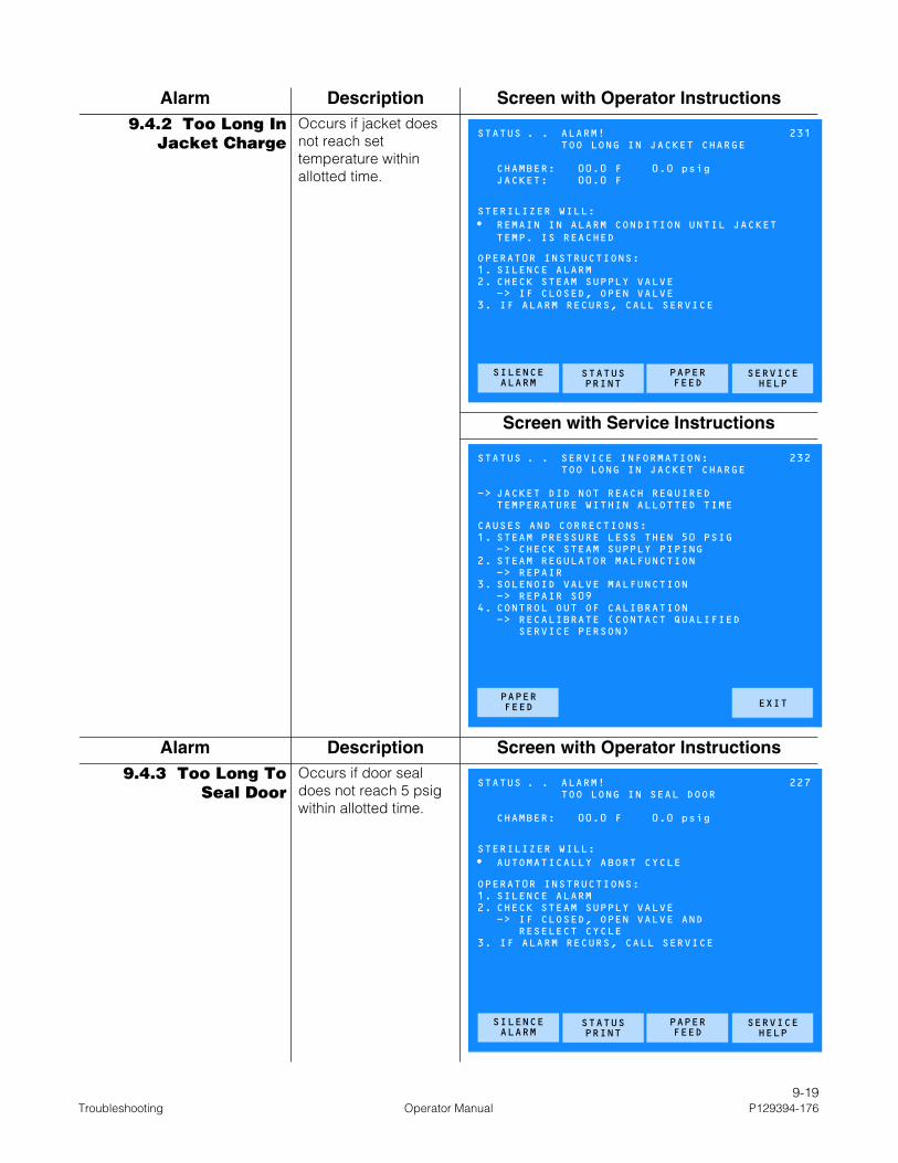
Alarm Description Screen with Operator Instructions9.4.2 Too Long In
Jacket ChargeOccurs if jacket does not reach set temperature within allotted time.
Screen with Service Instructions
Alarm Description Screen with Operator Instructions9.4.3 Too Long To
Seal DoorOccurs if door seal does not reach 5 psig within allotted time.
STATUS . . ALARM! 231TOO LONG IN JACKET CHARGE
CHAMBER: 00.0 F 0.0 psigJACKET: 00.0 F
STERILIZER WILL:• REMAIN IN ALARM CONDITION UNTIL JACKET
TEMP. IS REACHED
OPERAT0R INSTRUCTIONS:1. SILENCE ALARM2. CHECK STEAM SUPPLY VALVE
-> IF CLOSED, OPEN VALVE3. IF ALARM RECURS, CALL SERVICE
SERVICEHELP
STATUSPRINT
SILENCEALARM
PAPERFEED
STATUS . . SERVICE INFORMATION: 232TOO LONG IN JACKET CHARGE
-> JACKET DID NOT REACH REQUIRED TEMPERATURE WITHIN ALLOTTED TIME
CAUSES AND CORRECTIONS:1. STEAM PRESSURE LESS THEN 50 PSIG
-> CHECK STEAM SUPPLY PIPING2. STEAM REGULATOR MALFUNCTION
-> REPAIR3. SOLENOID VALVE MALFUNCTION
-> REPAIR S094. CONTROL OUT OF CALIBRATION
-> RECALIBRATE (CONTACT QUALIFIED SERVICE PERSON)
PAPERFEED EXIT
STATUS . . ALARM! 227TOO LONG IN SEAL DOOR
CHAMBER: 00.0 F 0.0 psig
STERILIZER WILL:
• AUTOMATICALLY ABORT CYCLE
OPERAT0R INSTRUCTIONS:1. SILENCE ALARM2. CHECK STEAM SUPPLY VALVE
-> IF CLOSED, OPEN VALVE AND RESELECT CYCLE
3. IF ALARM RECURS, CALL SERVICE
SERVICEHELP
STATUSPRINT
SILENCEALARM
PAPERFEED
9-19Troubleshooting Operator Manual P129394-176
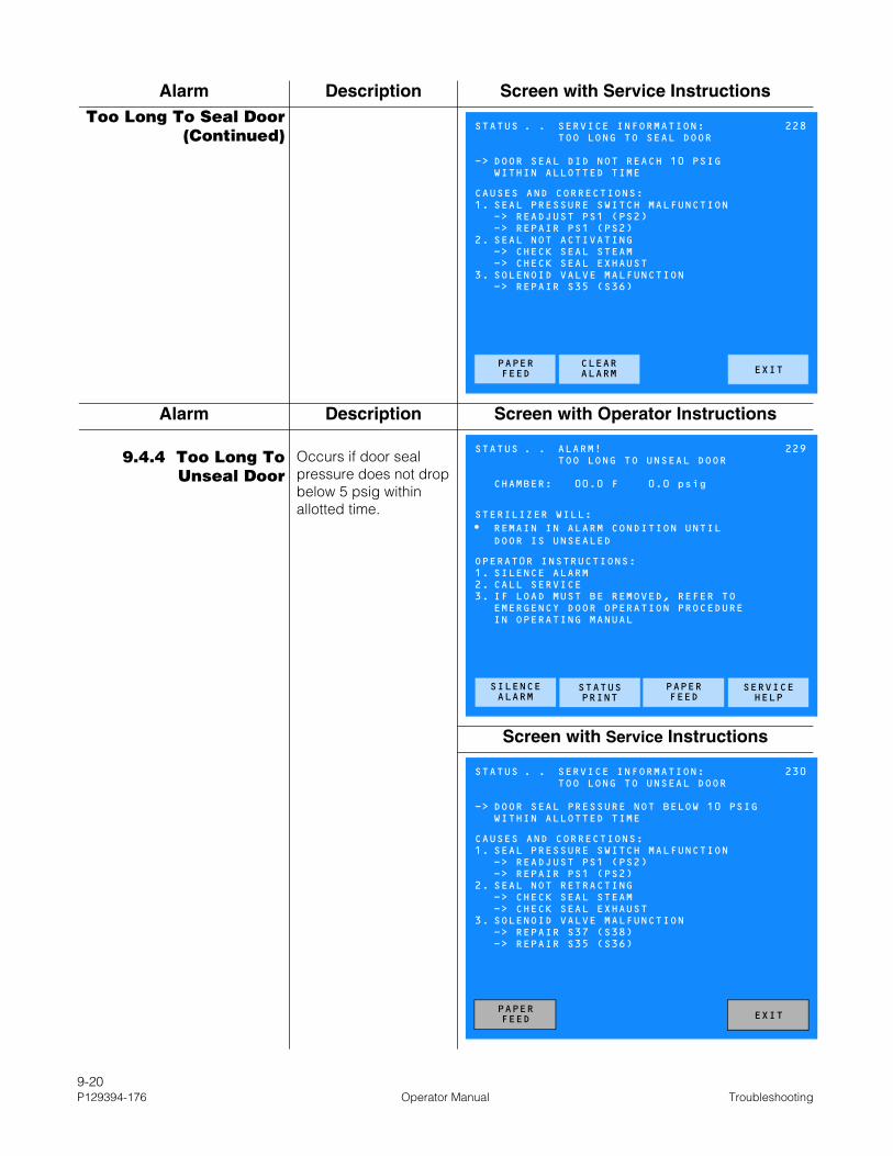
Alarm Description Screen with Service InstructionsToo Long To Seal Door
(Continued)
Alarm Description Screen with Operator Instructions
9.4.4 Too Long ToUnseal Door
Occurs if door seal pressure does not drop below 5 psig within allotted time.
Screen with Service Instructions
STATUS . . SERVICE INFORMATION: 228TOO LONG TO SEAL DOOR
-> DOOR SEAL DID NOT REACH 10 PSIG WITHIN ALLOTTED TIME
CAUSES AND CORRECTIONS:1. SEAL PRESSURE SWITCH MALFUNCTION
-> READJUST PS1 (PS2)-> REPAIR PS1 (PS2)
2. SEAL NOT ACTIVATING-> CHECK SEAL STEAM-> CHECK SEAL EXHAUST
3. SOLENOID VALVE MALFUNCTION-> REPAIR S35 (S36)
PAPERFEED EXIT
CLEARALARM
STATUS . . ALARM! 229TOO LONG TO UNSEAL DOOR
CHAMBER: 00.0 F 0.0 psig
STERILIZER WILL:
• REMAIN IN ALARM CONDITION UNTIL DOOR IS UNSEALED
OPERAT0R INSTRUCTIONS:1. SILENCE ALARM2. CALL SERVICE3. IF LOAD MUST BE REMOVED, REFER TO
EMERGENCY DOOR OPERATION PROCEDURE IN OPERATING MANUAL
SERVICEHELP
STATUSPRINT
SILENCEALARM
PAPERFEED
STATUS . . SERVICE INFORMATION: 230TOO LONG TO UNSEAL DOOR
-> DOOR SEAL PRESSURE NOT BELOW 10 PSIG WITHIN ALLOTTED TIME
CAUSES AND CORRECTIONS:1. SEAL PRESSURE SWITCH MALFUNCTION
-> READJUST PS1 (PS2)-> REPAIR PS1 (PS2)
2. SEAL NOT RETRACTING-> CHECK SEAL STEAM-> CHECK SEAL EXHAUST
3. SOLENOID VALVE MALFUNCTION-> REPAIR S37 (S38)-> REPAIR S35 (S36)
PAPERFEED EXIT
9-20P129394-176 Operator Manual Troubleshooting

Alarm Description Screen with Operator Instructions9.4.5 Chamber
Pressure TransducerFailure
Occurs if chamber pressure reading is outside the normal range.
Screen with Service Instructions
Alarm Description Screen with Operator Instructions9.4.6 Chamber
Temperature ProbeFailure
Occurs if chamber temperature reading is outside the normal range.
STATUS . . ALARM! 217CHAMBER PRESSURE TRANSDUCER FAIL-
URE
CHAMBER: 00.0 F 0.0 psig
STERILIZER WILL:• AUTOMATICALLY ABORT CYCLE
OPERAT0R INSTRUCTIONS:1. SILENCE ALARM
SERVICEHELP
STATUSPRINT
SILENCEALARM
PAPERFEED
STATUS . . SERVICE INFORMATION: 218CHAMBER PRESSURE TRANSDUCER FAIL-
URE
-> TRANSDUCER, CP, OUTPUT VOLTAGE IS OUTSIDE NORMAL RANGE
CAUSES AND CORRECTIONS:1. LOOSE CONNECTION IN TRANSDUCER WIRING
-> REPAIR2. TRANSDUCER FAILED
-> REPAIR-> RECALIBRATE
3. CONTROL OUT OF CALIBRATION-> RECALIBRATE (CONTACT QUALIFIED SERVICE PERSON)
4. MAIN CONTROL FAILURE-> CHECK CONTROL BOARD POWER STATUS LEDs-> REPLACE CONTROL BOARD
PAPERFEED EXIT
STATUS . . ALARM! 211CHAMBER TEMPERATURE PROBE FAILURE
CHAMBER: 00.0 F 0.0 psig
STERILIZER WILL:
• AUTOMATICALLY ABORT CYCLE
OPERAT0R INSTRUCTIONS:1. SILENCE ALARM2. CALL SERVICE
SERVICEHELP
STATUSPRINT
SILENCEALARM
PAPERFEED
9-21Troubleshooting Operator Manual P129394-176

Alarm Description Screen with Service InstructionsChamber Temperature Probe Failure (Continued)
Alarm Description Screen with Operator Instructions9.4.7 Jacket
Temperature ProbeFailure
Occurs if jacket temperature reading is outside the normal range.
STATUS . . SERVICE INFORMATION: 212CHAMBER TEMPERATURE PROBE FAILURE
-> RTD PROBE, CT, OUTPUT IS OUTSIDE NORMAL RANGE
CAUSES AND CORRECTIONS:1. LOOSE CONNECTION IN PROBE WIRING
-> REPAIR2. PROBE FAILED
-> REPAIR-> RECALIBRATE
3. CONTROL OUT OF CALIBRATION-> RECALIBRATE (CONTACT QUALIFIED SERVICE PERSON)
4. MAIN CONTROL FAILURE-> CHECK CONTROL BOARD POWER STATUS LEDs-> REPLACE CONTROL BOARD-> RECALIBRATE
PAPERFEED EXIT
STATUS . . ALARM! 213JACKET TEMPERATURE PROBE FAILURE
CHAMBER: 00.0 F 0.0 psig
STERILIZER WILL:• AUTOMATICALLY ABORT CYCLE
OPERAT0R INSTRUCTIONS:1. SILENCE ALARM2. CALL SERVICE
SERVICEHELP
STATUSPRINT
SILENCEALARM
PAPERFEED
9-22P129394-176 Operator Manual Troubleshooting

Alarm Description Screen with Service InstructionsJacket Temperature
Probe Failure(Continued)
Alarm Description Screen with Operator Instructions9.4.8 Door Switch
FailureOccurs if door seal switch contact is made but door switch is still open.
Screen with Service Instructions
STATUS . . SERVICE INFORMATION: 214JACKET TEMPERATURE PROBE FAILURE
-> RTD PROBE, JT, OUTPUT IS OUTSIDE NORMAL RANGE
CAUSES AND CORRECTIONS:1. LOOSE CONNECTION IN PROBE WIRING
-> REPAIR2. PROBE FAILED
-> REPAIR-> RECALIBRATE
3. CONTROL OUT OF CALIBRATION-> RECALIBRATE (CONTACT QUALIFIED SERVICE PERSON)
4. MAIN CONTROL FAILURE-> CHECK CONTROL BOARD POWER STATUS LEDs-> REPLACE CONTROL BOARD-> RECALIBRATE
PAPERFEED EXIT
STATUS . . ALARM! 237DOOR SWITCH FAILURE
CHAMBER: 00.0 F 0.0 psig
STERILIZER WILL:
• AUTOMATICALLY ABORT CYCLE
• EXHAUST CHAMBER TO ATMOSPHERIC PRESSURE
OPERAT0R INSTRUCTIONS:1. SILENCE ALARM2. CALL SERVICE
SERVICEHELP
STATUSPRINT
SILENCEALARM
PAPERFEED
STATUS . . SERVICE INFORMATION: 238DOOR SWITCH FAILURE
-> DOOR SWITCH OPEN WHILE SEAL SWITCH CLOSED
CAUSES AND CORRECTIONS:1. DOOR SWITCH MALFUNCTION
-> CHECK LS1 (LS2) CONNECTIONS-> READJUST LS1 (LS2)-> REPAIR LS1 (LS2)
2. SEAL PRESSURE SWITCH MALFUNCTION-> READJUST PS1 (PS2)-> REPAIR LPS1 (PS2)
PAPERFEED EXIT
9-23Troubleshooting Operator Manual P129394-176

Alarm Description Screen with Operator Instructions9.4.9 Door Seal A
Switch MalfunctionOccurs if switched neutral relay, associated with door seal A, closed switch fails.
Screen with Service Instructions
Alarm Description Screen with Operator Instructions9.4.10 Board
Overtemp FailureOccurs if the temperature of the main control circuit board exceeds acceptable environmental conditions.
STATUS . . ALARM! 286DOOR A SEAL SWITCH MALFUNCTION
CHAMBER: 00.0 F 0.0 psig
STERILIZER WILL:• AUTOMATICALLY ABORT CYCLE
OPERAT0R INSTRUCTIONS:1. SILENCE ALARM2. CALL SERVICE
SERVICEHELP
STATUSPRINT
SILENCEALARM
PAPERFEED
STATUS . . SERVICE INFORMATION: 287DOOR A SEAL SWITCH MALFUNCTION
-> SEAL SWITCH CLOSED OUT OF CYCLE
CAUSES AND CORRECTIONS:1. SEAL SWITCH MALFUNCTION
-> CHECK LPS1 (PS2) FOR FAILED CLOSED2. 2. SHORTED CABLE
-> CHECK CABLE AT P19 FOR SHORT CIRCUIT
PAPERFEED EXIT
CLEARALARM
STATUS . . ALARM! 280BOARD OVERTEMP FAILURE
CHAMBER: 00.0 F 0.0 psig
STERILIZER WILL:• AUTOMATICALLY ABORT CYCLE
OPERAT0R INSTRUCTIONS:1. SILENCE ALARM2. CALL SERVICE
STATUSPRINT
SILENCEALARM
PAPERFEED
9-24P129394-176 Operator Manual Troubleshooting
10.1 General The material in this section is provided to allow for servicingcomponents of the sterilizer most likely to need attention. Theseprocedures are more advanced than cleaning and replacingexpendables (such as printer paper and door seals). Theseprocedures should always be performed by an experienced, trainedservice technician.
10.2 Air FilterReplacement
The purpose of the bacterial air filter is to filter air entering thesterilization chamber. The chamber is exposed to contaminationwhenever the filter or the air lines below the filter are opened. Keepthese components as clean as possible when servicing. Thebacterial air filter contains a replaceable filter cartridge; refer toTable 8-1. Preventative Maintenance Schedule for frequency.
1. Remove the old filter element and discard.
2. Insert the new filter, P129360-802.
WARNING – BURN HAZARD: Allow sterilizer and accessories to cool to room temperature before performing any cleaning or maintenance procedures.
WARNING – ELECTRIC SHOCK HAZARD: Disconnect all utilities to sterilizer before servicing. Do not service the sterilizer unless all utilities have been properly locked out. Always follow OSHA Lockout-Tagout and electrical safety-related work practice standards.
WARNING – PERSONAL INJURY HAZARD AND/OR EQUIPMENT DAMAGE HAZARD: The performance of the 510k cleared AMSCO C Series Sterilizer is validated as a system including components defined by STERIS in the Operator Manual and Service Manual for the AMSCO C Series Sterilizer. Substitution of unauthorized components can potentially lead to personal injury, damage or premature failure of the product and result in a unit configuration that is inconsistent with the validated, FDA cleared product. STERIS' warranty is void if components are used that are not approved. DO NOT USE components that are not validated as part of the AMSCO C Series Sterilizer.
�
�
�
SERVICE PROCEDURES
Service Procedures Operator Manual P
10
10-1129394-176

Figure 10-1. Serviceable Components
10-2P129394-176 Operator Manual Service Procedures

10.3 Clean Strainers The strainers should be opened for cleaning after initial start-up andat least twice a year thereafter (refer to Table 8-1. PreventativeMaintenance Schedule). Accumulation of sediment and rust willreduce pressure and flow. In extreme conditions, complete blockagemay occur.
Disassembly
Shut off supply and then vent pressure in line by running a shortsterilizer cycle. Abort cycle when no pressure is present in steam orwater lines.
1. Assure water and steam lines are still shut off.
2. Remove hex plug and gasket.
3. Pull out strainer screen from body.
4. Scrape and polish all rust and residue from strainer screen and body. Use a wire brush or steel wool. Be sure that all perforations are clear. Replace screen if damaged, rusted or corroded.
Figure 10-2. Remove Door Seal
Twist Tongue Depressor or
Similar Tool to Pry Out Seal
Location of Seal Reference
Indicators
Figure 10-3. Location of Seal Lot Data and Reference indicators
Rear of Door SealLocation of Seal Date Information
Location of Seal Reference
Indicators
Reference Indicators, Enlarged
WARNING – BURN HAZARD: Failure to shut off the steam supply when cleaning or replacing strainers can result in serious injury.
�
10-3Service Procedures Operator Manual P129394-176
Reassembly
1. Insert screen into strainer body. Ensure that no dirt or other particles remain in strainer body.
2. Replace and tighten hex plug. Use a new gasket if necessary.
3. Make certain all pipe connections are tight after assembly.
10.4 Door SealReplacement
Procedure
Refer to Figures 10-2 and 10-3.
This procedure should be performed by a qualified servicetechnician. If door seal requires replacement, perform the following:
1. Allow sterilizer chamber and end frame to cool to room temperature.
2. Open sterilizer door.
3. Use flat tool with rounded edges (such as a tongue depressor or non-serrated table knife) to pry and twist one section of the seal partially from the groove. Refer to Figure 10-2.
4. Grasp the raised section of the seal and pull the remainder from the end frame groove.
5. Examine the end frame groove for debris or residue. Clean if necessary.
6. Install new seal as follows:
NOTE: Ensure that lot data molded into rear of seal (refer toFigure 10-3) is at the bottom of the groove.
• Do not use a sharp instrument to install the seal.
• Do not stretch the seal.
a. Align right and left reference indicators with drill point reference marks in seal groove, align top and bottom indicators with the drill point reference marks in seal groove.
NOTE: Reference indicators are located inside the rear groove ofdoor seal, at the middle of each side (refer to Figure 10-4).
b. Press seal in at each reference point with fingertips.
c. Press seal in at each corner with fingertips.
d. Press remainder of the seal into end frame groove.
7. Test installation.
a. Attempt to close the door. If the door sticks or will not fully close at any point in its travel, check to make sure the seal has been fully pressed into the groove.
b. Run a shortened test cycle to determine if the door seals adequately. If steam leaks from around the door or the seal, abort the cycle and examine the seal to ensure it has been properly seated in the end frame groove. Once re-seated, run another test cycle. If the door fails to seal following the second test, another problem may exist. Contact your supervisor before using the sterilizer further.
At the end of the cycle, ensure seal has retracted fully intothe groove.
WARNING – BURN HAZARD: Allow sterilizer and accessories to cool to room temperature before performing any cleaning or maintenance procedures.
�
10-4P129394-176 Operator Manual Service Procedures
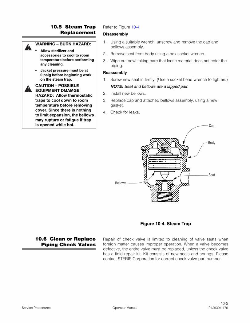
10.5 Steam TrapReplacement
Refer to Figure 10-4.
Disassembly
1. Using a suitable wrench, unscrew and remove the cap and bellows assembly.
2. Remove seat from body using a hex socket wrench.
3. Wipe out bowl taking care that loose material does not enter the piping.
Reassembly
1. Screw new seat in firmly. (Use a socket head wrench to tighten.)
NOTE: Seat and bellows are a lapped pair.
2. Install new bellows.
3. Replace cap and attached bellows assembly, using a new gasket.
4. Check for leaks.
Figure 10-4. Steam Trap
10.6 Clean or ReplacePiping Check Valves
Repair of check valve is limited to cleaning of valve seats whenforeign matter causes improper operation. When a valve becomesdefective, the entire valve must be replaced, unless the check valvehas a field repair kit. Kit consists of new seals and springs. Pleasecontact STERIS Corporation for correct check valve part number.
WARNING – BURN HAZARD:
• Allow sterilizer and accessories to cool to room temperature before performing any cleaning.
• Jacket pressure must be at0 psig before beginning work on the steam trap.
CAUTION – POSSIBLE EQUIPMENT DMAMGE HAZARD: Allow thermostatic traps to cool down to room temperature before removing cover. Since there is nothing to limit expansion, the bellows may rupture or fatigue if trap is opened while hot.
�
�
Cap
Body
Bellows
Seat
10-5Service Procedures Operator Manual P129394-176

10.7 RebuildSolenoid Valves
Refer to Figure 10-5.
Solenoid valves can be rebuilt following the instructions included inthe repair kit for the specific valve. Refer to Table 10-1.Replacement Parts, for correct kit number.
Figure 10-5. Internal Pilot-Operated Solenoid Valve.
10.8 Safety Valve Test The safety valves are to be tested periodically (refer to Table 8-1.Preventive Maintenance Schedule at the beginning of SECTION 8,ROUTINE MAINTENANCE).
1. Prevent damage during testing by ensuring that at least 75% of the rated pressure is in the chamber. Check current pressure level by observing chamber pressure gauge.
2. Open the try lever and hold the valve open for one to two seconds.
3. Allow the try lever to snap shut.
Any adjustments to the safety relief valve should be performed by aqualified service technician. Improper adjustments to this valve mayresult in inadequate sterilizer operation.
Stationary Core
Shading Coil
Moveable Core
Spring
INLET OUTLET
Body
Bleed Orifice
Diaphragm
Housing
DIN Connector
Prongs
Solenoid Coil
Core Tube
Pilot Orifice
INLET OUTLET
WARNING – BURN HAZARD: Proper testing of the safety valve requires the valve to be operated under pressure. Exhaust from the safety valve is hot and can cause burns. Proper safety attire (gloves, eye protection, insulated overall) as designated by OSHA, is required. Testing is to be performed by qualified service personnel only.
CAUTION – POSSIBLE EQUIPMENT DMAMGE HAZARD: Actuation at less than 75% of rated pressure can allow debris to contaminate the seat and cause the safety valve to leak. A leaking safety valve must be replaced.
�
�
10-6P129394-176 Operator Manual Service Procedures

10.9 RecommendedSpare Parts
To order replacement parts and/or supply products, proceed asfollows:
1. Include the description and part/order number as listed in Table 10-1. Replacement Parts.
2. Include the model and serial numbers of your sterilizer on your order.
3. Send your order directly to the sales and service center serving your area.
Contact your sales representative for recommendations on cleaningproducts, biological indicators or parts that are not listed inTable 10-1. Replacement Parts.
NOTE: Use only STERIS authorized parts on this equipment. Useof unauthorized parts will void the warranty.
10-7Service Procedures Operator Manual P129394-176
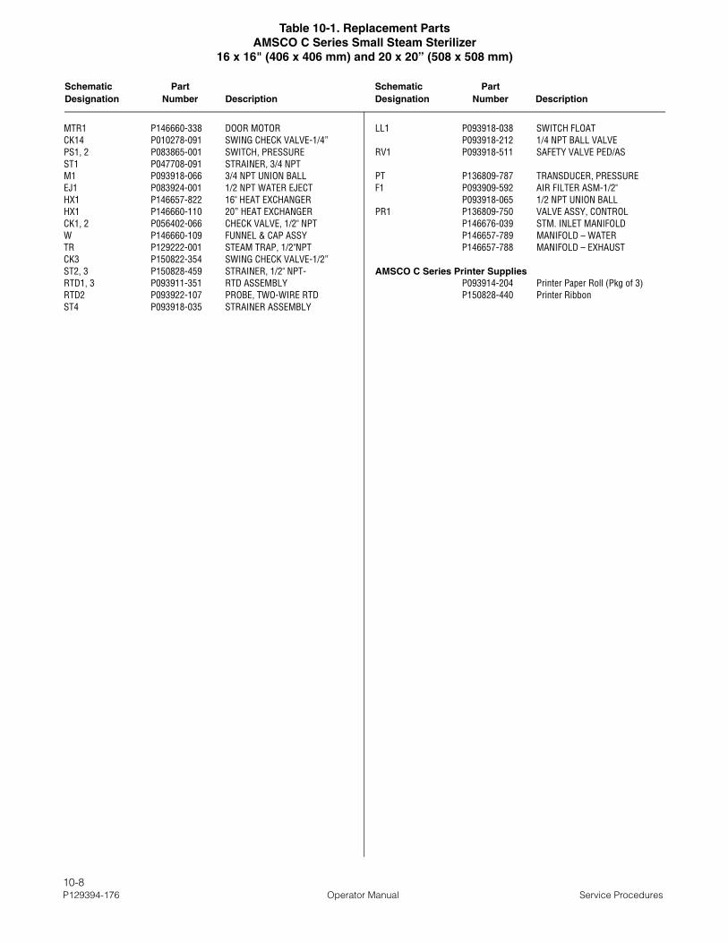
10-8P129394-176 Operator Manual Service Procedures
MTR1 P146660-338 DOOR MOTORCK14 P010278-091 SWING CHECK VALVE-1/4”PS1, 2 P083865-001 SWITCH, PRESSUREST1 P047708-091 STRAINER, 3/4 NPTM1 P093918-066 3/4 NPT UNION BALLEJ1 P083924-001 1/2 NPT WATER EJECTHX1 P146657-822 16" HEAT EXCHANGERHX1 P146660-110 20” HEAT EXCHANGERCK1, 2 P056402-066 CHECK VALVE, 1/2" NPTW P146660-109 FUNNEL & CAP ASSYTR P129222-001 STEAM TRAP, 1/2"NPTCK3 P150822-354 SWING CHECK VALVE-1/2”ST2, 3 P150828-459 STRAINER, 1/2" NPT-RTD1, 3 P093911-351 RTD ASSEMBLYRTD2 P093922-107 PROBE, TWO-WIRE RTDST4 P093918-035 STRAINER ASSEMBLY
LL1 P093918-038 SWITCH FLOATP093918-212 1/4 NPT BALL VALVE
RV1 P093918-511 SAFETY VALVE PED/AS
PT P136809-787 TRANSDUCER, PRESSUREF1 P093909-592 AIR FILTER ASM-1/2"
P093918-065 1/2 NPT UNION BALLPR1 P136809-750 VALVE ASSY, CONTROL
P146676-039 STM. INLET MANIFOLDP146657-789 MANIFOLD – WATERP146657-788 MANIFOLD – EXHAUST
AMSCO C Series Printer SuppliesP093914-204 Printer Paper Roll (Pkg of 3)P150828-440 Printer Ribbon
Table 10-1. Replacement PartsAMSCO C Series Small Steam Sterilizer
16 x 16" (406 x 406 mm) and 20 x 20” (508 x 508 mm)
Schematic PartDesignation Number Description
Schematic PartDesignation Number Description

10-9S
ervice Proced
uresO
perator M
anualP
129394-176
Fig
ure 10-1. P
ipin
g S
chem
atic

10.10 Waste ProductsDisposal
The following are waste materials associated with the sterilizer. Whendisposing of waste materials, be compliant with federal, state andlocal regulations.
• Printer paper – recyclable.
• Printer ribbon – not recyclable.
• Water filters – not recyclable.
• Waste water – 57 L/min (15 gal/min).
• Entire sterilizer (end-of-life) – Contact STERIS Corporation fordisposal or recycling recommendations.
10-10P129394-176 Operator Manual Service Procedures