Operation Manual 3.6 L4 TCD 3.6 L4€¦ · Notes Notes gine, the use of DEUTZ original parts is...
72
Operation Manual TD 3.6 L4 TCD 3.6 L4 A® DEUTZ
Transcript of Operation Manual 3.6 L4 TCD 3.6 L4€¦ · Notes Notes gine, the use of DEUTZ original parts is...

Operation Manual
TD 3.6 L4 TCD 3.6 L4
A® DEUTZ

Notes Notes gine, the use of DEUTZ original parts is pre-
• This engine is defined exclusively for purpose scribed. These ar~ specia_lly designed for your according to the scope of delivery and built by engine and guap ntee perf~ct operation. the equipment manufacturer (use for the intend- Non-compliance results in th~ expiry of the war-ed purpose). Any other use above and beyond ranty! \ this will be considered as misuse. The manufac- Maintenance/cleaning work on t~e engine may turer will not accept any liability for damages re- only be cart'ied out ..yll~~he engiCe is not run-suiting from this. The user bears the sole risk. ning an~tias ooo17d do . .\
• Use for the intended purpose also includes ob- When doing this71make s re that the electrical servance of the operating, maintenance and re- systeo< is_ swit~bed off (rem~e ignitiOIJ. key). pair conditions specified by the manufacturer. The,lpeetficaljons for aCCide~ prevenfton with The engine should only be operated, serviced ell}ttrical sytems (e.g. VDE-0100/-01011·0104/-and repaired by personnel trained in its use and ~f05 Elec!Jical protective measures agains dan-the hazards involved. yerous contact v~tages)'must be ~bserved. The pertinent rules for the prevention of acci- Cover ~( electric I compo, ents tigntzy when dents and other generally recognised safety and clean!SJg with liqu ds. \ industrial medicine rules must be observed. D~.~ot work on th~fuel sy tem while tl'l~ngine
• When the engine is running there is a danger of is ~nning - Dange to life injury caused by: Vj_ait for the pressu e to ~e relieved once IJ.e en-- rotating and hot components g1ne has shut down (for engines with comrrtQn - on motors with external ignition (high e4.ectr"- rail, approx. 5 minut~, otherwise 1 minute) a
cal voltage). Contact must be avoided! the system is under ~iQh pressure- Danger to
• Unauthorised engine modifications will invali ate life! U any liability claims against the manufact
7r r for During the first trial run do not stand in the dan-
resultant damage. ger area of the engine.
Equally, manipulations to the i njectio~nd con- Danger due to highl)re$sure in case of leaks -trol system can affect the engine's pe ormance Danger to life! 6) and the exhaust characteristics. Adt.J renee to - In case of lea s imme iately contact work-legislation on pollution can no lon~er be gu~an- shop. teed under such conditions. /. l - When working on the fuel system, make sure
• Do not change the cooling air ~ed area t,o the that the engine is not started inadvertently blower of fan. An unobstructet oooling air supply..-----during repairs~Danger to lifet---------1 must be guaranteed.
The manufacturer will accept o,l;.;;ia:;;;bi;,;,;lit:!..y_ .;.;;fo::..rd.::;a:::.m::..----------------~--------.J age resulting from this.
• When carrying out maintenance work on the en-
Dear customer,
Congratulations on the purchase of your DEUTZ engine.
DEUTZ air/liquid-cooled engines are developed for a broad spectrum of applications. Consequently, a wide range of variants is ·offered to meet the requirements of specific cases.
The engine is equipped accordingly for the particular installation situation, i.e. not all the components described in the operating manual are installed in your engine.
We have endeavoured to highlight any differences so that you will be able to locate the operating and maintenance instructions applicable to your engine more quickly and easily.
Please make sure that this operating manual is available to everyone involved in the operation, maintenance and repair of the engine and that they have understood the contents.
If you have any queries, please contact us, we'll be happy to advise you.
Sincerely,
DEUTZAG
Engine serial number
Please enter the engine serial number here. This will simplify the handling of customer service, repair and spare parts queries.
Components of the exhaust aflertreatment system
Please enter the serial numbers of the exhaust aftertreatment components.
Diesel oxidation catalytic converter
Diesel particle filter
Notes
We reserve the right to make technical changes to the descriptions and data in this operating manual in the interest of further development of the engines.
This document may only be reprinted and reproduced, even in part, with our express permission.
Foreword

Table of contents Notes. . . . . . . . . . . . . . . . . . . . . . 2
Foreword ............•....... . 3 General . . . . . . . . . . . . . . . . . . . 5
2 Engine description . . . . . . . . . . • . . . 7
Model . . . . . . . . . . . . . . . . • . . 7
Engine illustrations . . . . . . . . . . . . . . 1 0 Lubricating oil diagram . . . . . . • . . . . . 16
Fuel diagram .... .. . . .. . . .... . 17
Coolant diagram .... . . . .• . . .. .. 18
Exhaust gas recirculation . . . . . . . . . . . 19
Exhaust gas aftertreatment. . . . . . . . . . 20
Electrics/Eiectronics . . . . . . . . . . . . . 21
3 Operation . . . . . . . . . . . . . . . . . . . 23
Ambient conditions . . . . . . . . . . . . . . 23
Initial commissioning . . . . . . . . 24
Starting process . . . . . . . . . . . • . . . 26
Operation monitoring . . . . . . . . . . . . . 27
Exhaust gas aftertreatment system .... .. 31
Passive regeneration . . . . . . . . . . . . . 32
Stopping process . . . . . . . . . • . . . . . 35
4 Operating media . . . . . . . . . . . . . . . 36
Lubricating oil . . . . . . . . . . • • . . . . . 36
Fuel ... ... .. ... .... ...... . 39
Coolant . ... .. . ......•...... 40
5 Maintenance . . . . . . . . . . . . . . . . .41
Maintenance schedule . . . . . . . . . . . . 41
6 Servicing and maintenance work. . . . . . . 44
Lubricating oil system. . . . . . . . . . . . . 44
Fuel system. . . . . . . . . . . . . . . . . . 46
Cooling system . . . . . . . . . . . • . . . . 49
Engine cleaning .......... .. .... 51
Suction system . . . . . . . 52
Belt drives . . . . . . . . . . . . . . . . . . 54
Electrical system . . . . . . . . • . . . . . . 56
7 Faults ... ... .. . .... • . . ..... 58
Fault table . . . . . . . . . . . . . . . . 58
Engine management . . . . . . . . . . . . . 62
8 Transport and storage ... . ....... . 64
Transport ................... 64
Engine corrosion protection . . . . . . . . . 65
9 Technical data . . . . . . . . . . . . • . . .67 Engine and setting data . . . . . . . . . . . 67 Tools .............. ..•.. .. 69

DEUTZ diesel engines
DEUTZ diesel engines and the appropriate exhaust aftertreatment components are the result of years of research and development. The detailed know-how gained by this in connection with the high quality demands are the guarantee for production of engines with a long life, high reliability and low fuel consumption. Naturally the high demands for protection of the environment are also met.
Safety precautions when the engine is running
Maintenance work or repairs may only be performed on the shut-down engine. Make sure that the engine cannot be started inadvertently- Danger of accident!
After repair work: Check that all guards have been replaced and that all tools have been removed from the engine.
Observe industrial safety regulations when running the engine in an enclosed space or underground.
When working on the running engine, work clothing must be close fitting.
Never fill the fuel tank while the engine is running.
Service and Maintenance
Service and maintenance are also decisive for whether the engine satisfactorily meets the set demands. Recommended service intervals must therefore be observed and service and maintenance work must be carried out conscientiously.
Special care should be taken under abnormally demanding operating conditions.
Original DEUTZ parts
Original DEUTZ parts are subject to the same strict quality demands as the DEUTZ engines. Further de-
velopments for improving the engines are also introduced in the original DEUTZ parts of course. Only the use of original DEUTZ parts manufactured according to the state-of-the-art can guarantee perfect functioning and high reliability.
DEUTZ Xchange components
DEUTZ replacement parts are a low-cost alternative. Of course, the quality standards here are just as high as for new parts. DEUTZ replacement parts are equal to the original DEUTZ parts in function and reliability.
Asbestos
The gaskets used in this engine con.tain no asbestos. Please use the appropriate original DEUTZ parts for maintenance and repair work.
Service
We want to preserve the high performance of our engines, and with it the confidence and satisfaction of our customers. We are therefore represented worldwide by a network of service branches.
The DEUTZ name does not merely stand for engines that are the products of extensive development work, DEUTZ also stands for complete service packages that ensure optimum operation of our engines, and for customer services operations that you can count on.
Please contact your DEUTZ-partner in case of malfunctions and sare parts inquiries. Our specially trained personnel will ensure fast, professional repairs using original DEUTZ spare parts in case of damage.
The DEUTZ home page gives you a continuously upto-date overview of the service partners in your vicin-
General ity with notes on product responsibilities and services. Or you can use another fast, convenient way via the Internet under www.deutzshop.de. The DEUTZ P@rts Online parts catalogue gives you a direct contact to your nearest local service partner.
california Proposltlon 65 Warning Diesel engines and some of its constituents are known to the State of California to cause cancer birth defects and other reproductive harm. '
Masthead
DEUTZAG
OttostraBe 1
51149 Koln
Germany
Phone:
Fax:
E-Mail:
+49 (0) 221-822-0
+49 (0) 221-822-3525
www.deutz.com
II

II General Danger
Jl.\l This symbol is used for all safety instruc~ lions which, if not observed, present a di
rect danger to life and limb for the person involved. Observe these carefully. The attention of operating personnel should be drawn to these safety instructions. Furthermore, the legislation for "general regulations for safety and the prevention of accidents" must be observed.
Caution
J,(Sl This symbol indicates a danger to the part ~ and engine. The relevant instructions must
be observed, failure to do so can lead to destruction of the part and the engine.
Notes
W This symbol accompanies notes of a genEJ era! kind.

Model
Engine type designation
This manual covers the following engine types
TD 3.6 L4
TCD3.6 L4
TCD T Exhaust gas turbocharger
c Charge air cooler
D Diesel
,3.6 3.6 Displacement in litres
L4
L I in series
4 I No. of cylinders
Emissions legislation
1/,\l The engine and the corresponding EAT 19 system (Exhaust After Treatment) are
adapted to each other and linked by an appropriate electronic controller. They are only certified by the responsible authorities and comply with the permissible exhaust limits in this combination. Operation of the engine with other EAT systems is not allowed.
The engines of these operating instructions fulfi ll the following exhaust emissions regulations
TCD 3.6 >56 kW With exhaust aftertreatment system
USA !EPATier4i
EU !stage IIIB
TD3.6<56kW With exhaust aftertreatment system
USA I EPA Tier 4 final
EU !stage IV
TCD 3.6 >56 kW Without exhaust aftertreatment system
USA !EPA Tier Ill
EU !stage lilA
TD3.6<56kW Without exhaust aftertreatment system
USA !EPA Tier 4i
EU !stage IIIB
1/.\l The engines of this operating manual may 19 only be used with a functioning exhaust af
tertreatment system. (if included in the DEUTZ scope of supply)
Engine description
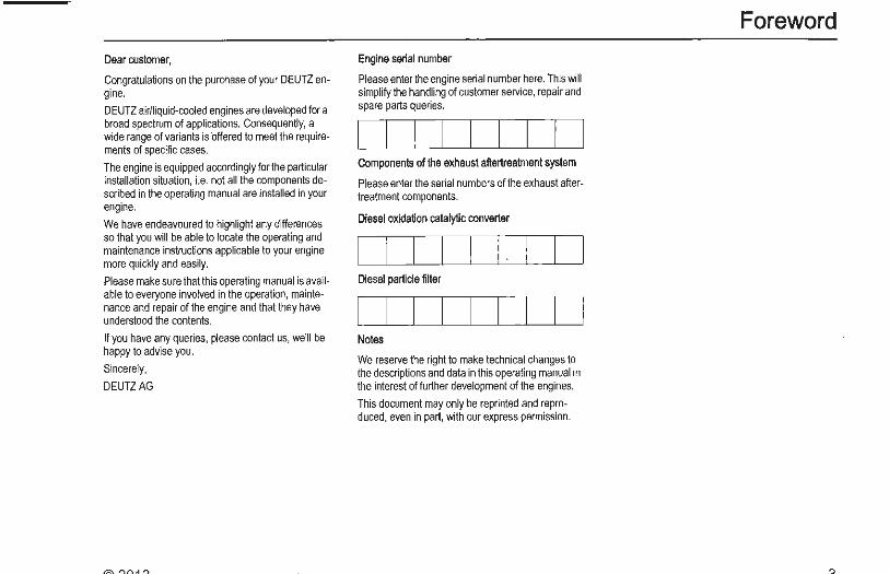
Rating plate
The type (A), engine number (B) and performance data are stamped on the rating plate.
The engine type and number must be stated when purchasing spare parts.
II Engine description
Location of the rating plate
The rating plate (C) is fixed to the cylinder head cover or the crankcase.
Engine serial number
The engine number (D) is stamped onto the crankcase (arrow) and onto the rating plate.
Model
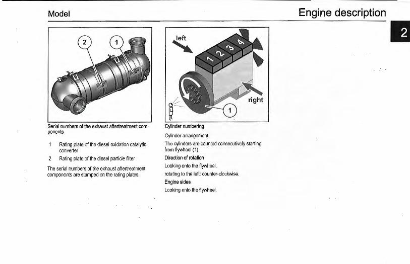
Serial numbers of the exhaust aftertreatment components
Rating plate of the diesel oxidation catalytic converter
The serial numbers of the exhaust aftertreatment components are stamped on the rating plates.
Model
Serial numbers of the exhaust aflertreatment components
Rating plate of the diesel oxidation catalytic converter
2 Rating plate of the diesel particle filter
The serial numbers of the exhaust aftertreatment components are stamped on the rating plates.
Cylinder numbering
Cylinder arrangement
The cylinders are counted consecutively starting from flywheel (1).
Direction of rotation
Looking onto the flywheel.
rotating to the left: counter-clockwise.
Engine sides
Looking onto the flywheel.
Engine description
II
Engine description
II Engine illustrations
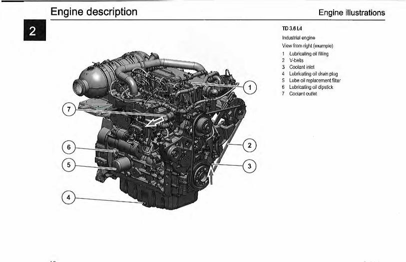
TD3.6L4
Industrial engine
View from right (example)
1 Lubricating oil filling 2 V-belts 3 Coolant inlet 4 Lubricating oil drain plug 5 Lube oil replacement filter 6 Lubricating oil dipstick 7 Coolant outlet
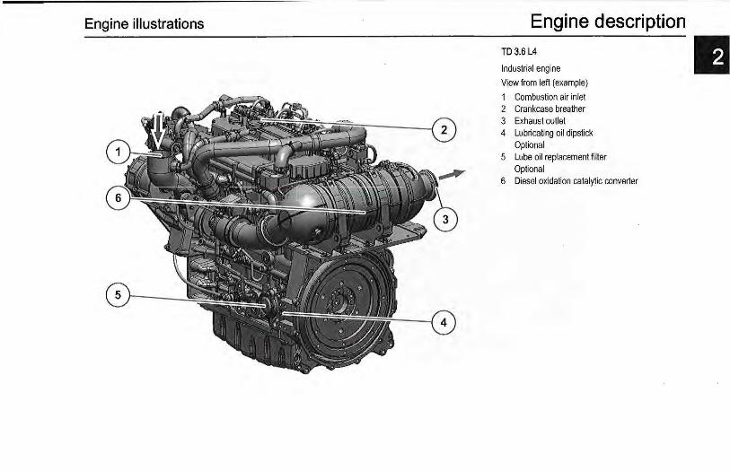
Engine illustrations Engine description TD3.6 L4
Industrial engine
View from left (example)
1 Combustion air inlet 2 Crankcase breather 3 Exhaust outlet 4 Lubricating oil dipstick
Optional 5 Lube oil replacement filter
Optional 6 Diesel oxidation catalytic converter
Engine description
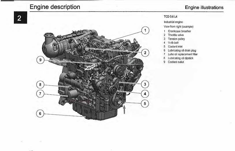
II Engine illustrations
TCD3.6 L4
Industrial engine
View from right (example)
1 Crankcase breather 2 Throttle valve 3 Tension pulley 4 V-ribbelt 5 Coolant inlet 6 Lubricating oil drain plug 7 Lube oil replacement filter 8 Lubricating oil dipstick 9 Coolant outlet
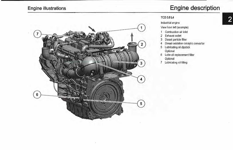
Engine illustrations Engine description TCD3.6 L4
Industrial engine
View from left (example)
1 Combustion air inlet 2 Exhaust outlet 3 Diesel particle filter 4 Diesel oxidation catalytic converter 5 Lubricating oil dipstick
Optional 6 Lube oil replacement filter
Optional 7 Lubricating oil filling
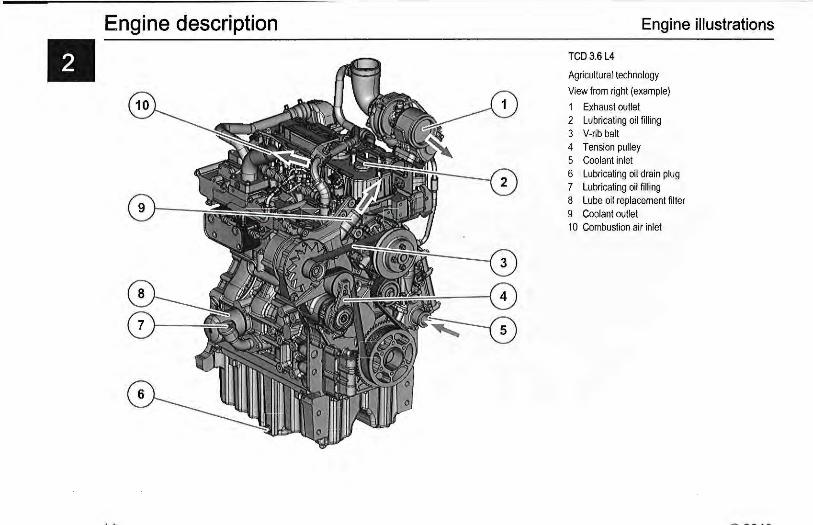
Engine description Engine illustrations
TCD3.6L4
Agricultural technology
View from right (example)
1 Exhaust outlet 2 Lubricating oil filling 3 V-rib belt 4 Tension pulley 5 Coolant inlet 6 Lubricating oil drain plug 7 Lubricating oil fill ing 8 Lube oil replacement filter 9 Coolant outlet 1 0 Combustion air inlet
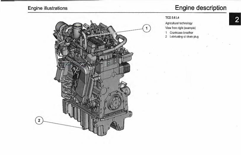
Engine illustrations Engine description
TCD3.6L4
Agricultural technology
View from right (example}
1 Crankcase breather 2 Lubricating oil drain plug
Engine description
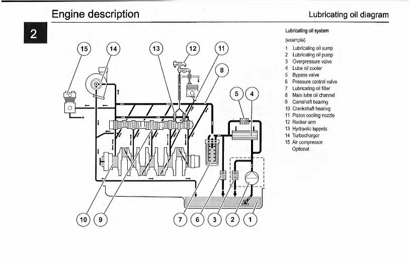
II Lubricating oil diagram
Lubricating oil system
(example)
1 Lubricating oil sump 2 Lubricating oil pump 3 Overpressure valve 4 Lube oil cooler 5 Bypass valve 6 Pressure control valve 7 Lubricating oil filter 8 Main lube oil channel 9 Camshaft bearing 10 Crankshaft bearing 11 Piston cooling nozzle 12 Rocker arm 13 Hydraulic tappets 14 Turbocharger 15 Air compressor
Optional

:· .. -....
0 • :· ..... . . . ~ ............... ..
gme descripti -------En °
'"""" . on ema~c (example)
1 Fuel tank 2 2 Fuel pre-filter 3 Fuel pump
(electrically pow 4 Exch ered) 5 F angeable fuel filter 6 uel transducer
High-pressure pump With - Control block FCU 7 Rail (Fuel Control Unit)
8 Injector 9 Check valve 10 Return line 11 Fuel ret 12 E . urn to fueltank
nglne control unit

Engine description Coolant diagram
Coolant schematic (example)
1 Coolant pump 2 Coolant supply for engine cooling 3 Cylinder pipe/head cooling 4 Lube oil cooler 5 Exhaust return cooler 6 Connection possibility for cab heating 7 Temperature transmitter 8 Thermostat 9 Cooler 10 Compensation tank
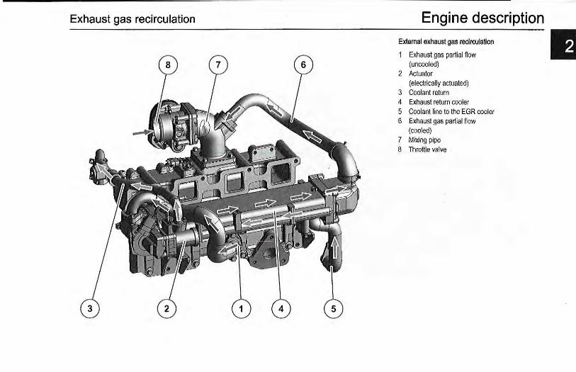
Exhaust gas recirculation Engine description External exhaust gas recirculation
1 Exhaust gas part ial flow (uncooled)
2 Actuator (electrically actuated)
3 Coolant return 4 Exhaust return cooler 5 Coolant line to the EGR cooler 6 Exhaust gas partial flow
(cooled) 7 Mixing pipe 8 Throttle valve
E

Engine description
II Exhaust gas aftertreatment
Exhaust aftertreatment system
Example:
1 Decoupling line 2 Differential pressure sensor 3 Exhaust temperature sensor 4 Diesel oxidation catalytic converter 5 Diesel particle filler
Optional 6 Differential pressure sensor 7 Exhaust outlet 8 Throttle valve

E lectrics/E lectron ics
G @ @). @
P3@ ~~(.jG\ ~ '-3'
[Q]
® ® @ @
Engine description Electronic engine control
Engine side
Rail pressure sensor 2 Charge air pressure transmitter, charge air tem-
perature transmitter 3 Coolant temperature transmitter 4 Engine control unit 5 Speed transmitter via camshaft 6 Speed transmitter via crankshaft 7 Fuel transducer 8 Lubricating oil pressure transmitter
(on the opposite side) 9 Central plug (for engine control)
Equipment side
10 Power supply (battery) 11 Signal outputs, e.g. for lamps, speed, engine op-
eration, etc. 12 Inputs (e.g. override button) 13 Accelerator 14 Hand throttle 15 Optional function selector switch, e.g. for P de
gree, type of controls, maximum curve, fixed speeds, etc.
16 Detachable key switch StarUStop 17 Diagnosis button 18 Error lamp 19 Diagnostic interface/CAN bus
II
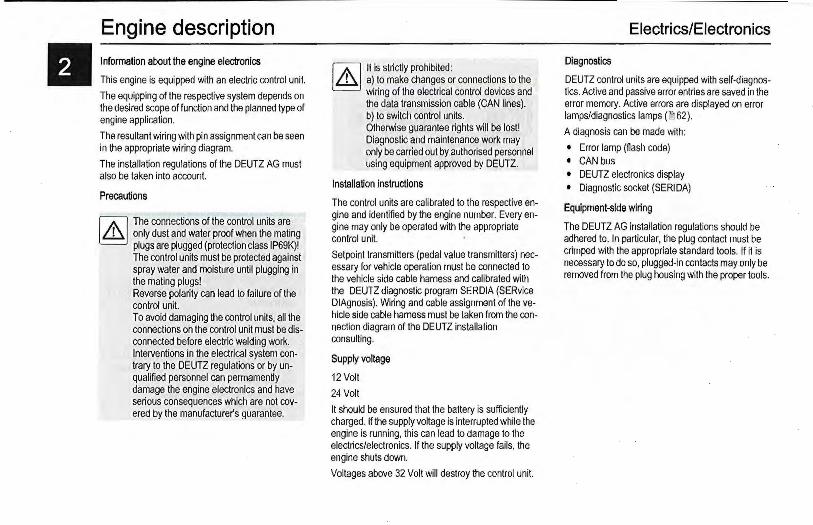
tl Engine description Information about the engine electronics
This engine is equipped with an electric control unit.
The equipping of the respective system depends on the desired scope of function and the planned type of engine application.
The resultant wiring with pin assignment can be seen in the appropriate wiring diagram.
The installation regulations of the DEUTZ AG must also be taken into account.
Precautions
1/,\l The connections of the control units are ~ only dust and water proof when the mating
plugs are plugged (protection class IP69K)! The control units must be protected against spray water and moisture until plugging in the mating plugs! Reverse polarity can lead to failure of the control unit. To avoid damaging the control units, all the connections on the control unit must be disconnected before electric welding work. Interventions in the electrical system contrary to the DEUTZ regulations or by unqualified personnel can permamently damage the engine electronics and have serious consequences which are not covered by the manufacturer's guarantee.
1/,\llt is strictly prohibited: ~ a) to make changes or connections to the
wiring of the electrical control devices and the data transmission cable (CAN lines). b) to switch control units. Otherwise guarantee rights will be lost! Diagnostic and maintenance work may only be carried out by authorised personnel using equipment approved by DEUTZ.
Installation instructions
The control units are calibrated to the respective engine and identified by the engine number. Every engine may only be operated with the appropriate control unit.
Setpoint transmitters (pedal value transmitters) necessary for vehicle operation must be connected to the vehicle side cable harness and calibrated with the DEUTZ diagnostic program SERDIA (SERvice DIAgnosis). Wiring and cable assignment of the vehicle side cable harness must be taken from the connection diagram of the DEUTZ installation consulting.
Supply voltage
12Volt
24 Volt
It should be ensured that the battery is sufficiently charged. If the supply voltage is interrupted while the engine is running, this can lead to damage to the electricslelectronics. If the supply voltage fails, the engine shuts down.
Voltages above 32 Volt will destroy the control unit.
Electrics/Eiectronics
Diagnostics
DEUTZ control units are equipped with self-diagnostics. Active and passive error entries are saved in the error memory. Active errors are displayed on error lamps/diagnostics lamps ( ~62).
A diagnosis can be made with:
• Error lamp (flash code) • CAN bus • DEUTZ electronics display • Diagnostic socket (SERIDA)
Equipment-side wiring
The DEUTZ AG installation regulations should be adhered to. In particular, the plug contact must be crimped with the appropriate standard tools. If it is necessary to do so, plugged-in contacts may only be removed from the plug housing with the proper tools.
Ambient conditions
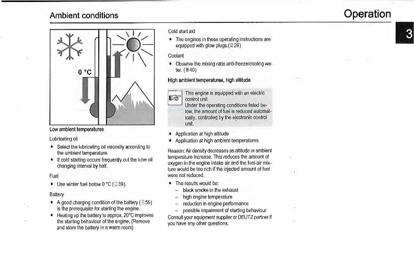
* Low ambient temperatures
Lubricating oil
• Select the lubricating oil viscosity according to the ambient temperature.
• If cold starting occurs frequently cut the lube oil changing interval by half.
Fuel
• Use winter fuel below 0 ' C (~ 39).
Battery
• A good charging condition of the battery ( 00 56) is the prerequisite for starting the engine.
• Heating up the battery to approx. 20'C improves the starting behaviour of the engine. (Remove and store the battery in a warm room).
Cold start aid
• The engines in these operating instructions are equipped with glow plugs.(lil26)
Coolant
• Observe the mixing ratio anti-freeze/cooling water. (IMO)
High ambient temperatures, high altitude
This engine is equipped with an electric control unit. Under the operating conditions listed below, the amount of fuel is reduced automatically, controlled by the el~ctronic control unit.
• Application at high altitude • Application at high ambient temperatures
Reason: Air density decreases as altitude or ambient temperature increase. This reduces the amount of oxygen in the engine intake air and the fuel-air mixture would be too rich if the injected amount of fuel were not reduced.
• The results would be: - black smoke in the exhaust - high engine temperature - reduction in engine performance - possible impairment of starting behaviour
Consult your equipment supplier or DEUTZ partner if you have any other questions.
Operation
II

II Operation Preparations for initial commissioning
(Maintenance schedule E 1 0)
• Remove engine corrosion protection • Remove any transport devices. • Check the battery and cable connections and
mount if necessary. • Check belt tension ( ~ 54) .
• Have the engine monitor or warning system checked by authorised personnel.
• Check the engine mounting. • Check that all hose unions and clips fit properly.
The following additional work must be carried out on generally overhauled engines:
• Check the fuel pre-filter and main filter and change if necessary.
• Check the intake air cleaner (if available, maintain according to maintenance indicator).
• Drain lubricating oil and condensation water from the charge air cooler.
• Fill with engine lube oil. • Fill the coolant system ( ~ 67).
Fill with engine lube oil
I.ISl Low lubricating oil level and overfi lling lead L£J to engine damage.
[d The engines are generally supplied without EJ lubricating oil filling.
Select lubricating oil quality and viscosity before filling. Order DEUTZ lubricating oils from your DEUTZ partner
• Fill the engine with lubricating oil via the lubricating oil filler neck.
• Observe the lubricating oil filling level (00 67).
Initial commissioning
·FUEL
Pour in fuel
I.ISl Nev~r fill the fuel tank while the engine is L£J runn1ng.
Ensure cleanliness. Do not spill fuel. Additional venting of the fuel system by a 5 minute trial run at idle speed or on low load is absolutely essential.
• Fuel low-pressure system must be vented before initial start-up after filling with the electric fuel supply pump. ~48
Only use clean commercially available brand diesel fuel. Observe fuel quality ( ~39).
Use summer or winter-grade fuel, depending on the ambient temperature.
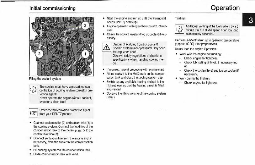
Initial commissioning
1.@ The coolant must have a prescribed con~ centration of cooling system corrosion pro
tection agent! Never operate the engine without coolant, even for a short time!
~ Order coolant corrosion protection agent EJ from your DEUTZ partner.
• Connect coolant outlet (2) and coolant inlet ( 1) to the cooling system. Connect the feed line of the compensation tank to the coolant pump or to the coolant inlet line (3).
• Connect ventilation line from the engine and, if necessary, from the cooler to the compensation tank.
• Fill cooling system via the compensation tank. • Close compensation tank with valve.
• Start the engine and run up until the thermostat opens (line (2) heats up).
• Engine operation with open thermostat 2 - 3 minutes.
• Check the coolant level and top up coolant if necessary.
rJ.\l Danger of scalding from hot coolant! ~ Cooling system under pressure! Only open
the cap when cool! Observe safety regulations and national specifications when handling cooling media.
• If required, repeat procedure with engine start. • Fill up coolant to the MAX mark on the compen
sation tank and close the cooling system cap. • Switch on any available heating and set to the
highest level so that the heating circuit is filled and vented.
• Observe the filling volume of the cooling system ( ~ 67) .
Operation Trial run
1.@ Additional venting of the fuel system by a 5 ~ minute trial run at idle speed or on low load
is absolutely essential.
Carry out a brief trial run up to operating temperature (approx. 90 •q after preparations.
Do not load the engine if possible.
• Work with the engine not running: - Check engine for tightness. - Check lubricating oil level, if necessary top
up. - Check the coolant level and top up coolant if
necessary. • Work during the trial run:
- Check engine for tightness.

II Operation Starting
W Before starting, make sure that nobody is ~ standing in the immediate vicinity of the en
gine or work machine. After repair work: Check that all guards have been replaced and that all tools have been removed from the engine. When starting with the flame glow plug/ glow plug/heating flange system do not use any other starting aid (e.g. injection with start pilot). Risk of accident!
~ If the engine fails to fire and the error lamp Li2J lights, the electronic engine control has ac
tivated the start lock to protect the engine. The start lock is released by switching off the system with the ignition key for about 30 seconds. Do not actuate the starter for more than 20 seconds. If the engine does not start up, wait for one minute and then repeat the starting process. If the engine does not start up after two attempts, determine the cause as per fault table {00 58). Do not run up the engine immediately to high idling speed I full load operation from cold.
Q Disconnect the engine by uncoupling deEJ vices to be driven where possible.
with oold starting device
• Insert key. - Position 0 =no operating voltage.
• Turn key to the right. - Position 1 = operating voltage. - Engine is ready for operation.
• Below the temperature specified in the electronic engine oontrol, the pre-heating phase begins with turning on the ignition.
• The electronic engine control controls and activates the current feed to the glow plugs via the engine coolant temperatures.
• Push the key in and turn further clockwise against spring pressure. - Level 2 = start.
• release the key as soon as the engine starts up. - The pilot lamps will go out.
If the starter is controlled by the electronic engine
Starting process
control via a relay:
• the maximum start duration is limited. • the pause between two start attempts is speci
fied. - the start is then continued automatically
• starting while the engine is running is prevented.
If the touch start function is programmed, a short start command with the ignition key in position 2 or a start button, if available, suffices.
Operation monitoring
Electronic engine control
The statuses are displayed by the error lamp.
The system monitors the condition of the engine and itself.
• Function test - Ignition on, error lamp lights up for approx. 2
seconds and then goes out. - Check the error lamp if there is no reaction
after switching on the ignition. • The lamp does not light
- After the lamp test an extinguished lamp indicates an error-free and trouble-free operating state within the scope of the control possibility.
• Continuous light - Error in the system. - Operation continued with restrictions. - The engine must be checked by a DEUTZ
partner. - If a lamp lights steadily a monitored measur
ing variable (e.g. coolant temperature, lubricating oil pressure) has left the permissible value range.
Depending on the fault, the engine power may be reduced by the electronic engine control to protect the engine.
• Flashing - Serious error in the system. - Switch off prompt for the operator. Attention:
Failure to do so will lead to loss of guarantee!
- The engine has reached switch-off condition. - Engine forced to run with power reduction to
cool the engine, with automatic shutdown if
necessary. - The switch-off process has been accom
plished. - There may be a start lock after engine stop. - The start lock is deactivated by turning off the
system with the ignition key for approx. 30s. - Additional control lamps, e.g. for lubricating
oil pressure or lubricating oil temperature, are switched on if necessary.
- optionally the power reduction can be bypassed, the automatic switch-off delayed or a start lock bypassed with the override key on the instrument panel to avoid critical situations. This brief deactivation of the engine protection functions is logge,d in the control unit.
The engine protection functions are released in co-operation with the equipment manufacturer and the DEUTZ installation consulting and may be designed individually. It is therefore absolutely essential to observe the operating instructions of the equipment manufacturer.
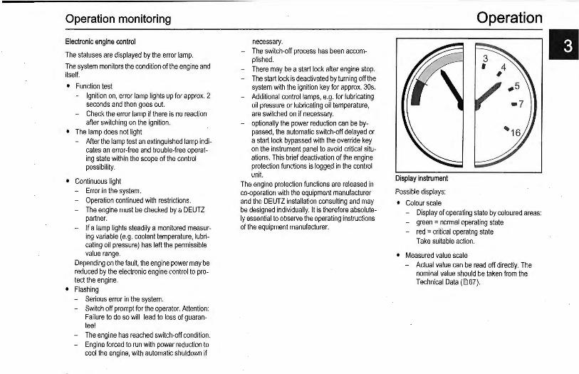
Display instrument
Possible displays:
• Colour scale
Operation
Display of operating state by coloured areas: - green = normal operating state
red = cri tical operatng state Take suitable action.
• Measured value scale - Actual value can be read off directly. The
nominal value should be taken from the Technical Data ( ial 67).
II

Operation Operation monitoring
Instruments/symbols Designation Possible display: Measure
• Lubricating oil pressure dis- Lubricating oil pressure in the red area Switch off engine play
Q Coolant temperature Coolant temperature too high Switch off engine
©i Lubricating oil temperature Lubricating oil temperature too high Switch off engine
@ Lubricating oil pressure pilot Lubricating oil pressure below minimum Switch off engine lamp
Lube oil level Lubricating oil level too low Fill up lube oil tJr.
'-"AA.A.A.J
Coolant level Coolant level too low Shut down the engine, allow to cool and top up cool-
~ ant
Operating hours counter Indicates the previous operating time of the engine Observe the maintenance intervals
111121311
Horn
D:J With acoustic signal See fault table (llt 58).
Operation monitoring Operation
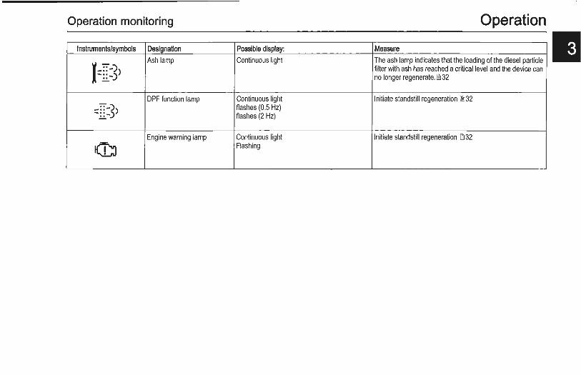
Instruments/symbols Designation Possible display: Measure
r-==-)) Ash lamp Continuous light The ash lamp indicates that the loading of the diesel particle
filter with ash has reached a critical level and the device can - ::-) no longer regenerate. ~ 32
DPF function lamp Continuous light Initiate standstill regeneration ~ 32 _::-)) flashes (0.5 Hz) -::-) flashes (2 Hz)
Engine warning lamp Continuous light Initiate standstill regeneration ~ 32
I(I;) Flashing
II Operation
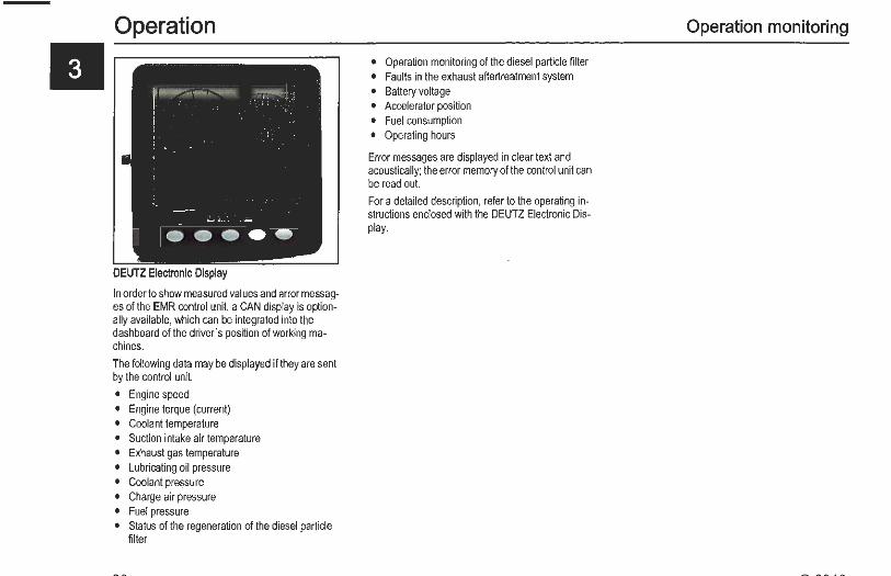
DEUTZ Electronic Display
In order to show measured values and error messages of the EMR control unit, a CAN display is optionally available, which can be integrated into the dashboard of the driver's position of working machines.
The following data may be displayed if they are sent by the control unit.
• Engine speed • Engine torque (current) • Coolant temperature • Suction intake air temperature • Exhaust gas temperature • Lubricating oil pressure • Coolant pressure • Charge air pressure • Fuel pressure • Status of the regeneration of the diesel particle
filter
• Operation monitoring of the diesel particle filter • Faults in the exhaust aftertreatment system • Battery voltage • Accelerator position • Fuel consumption • Operating hours
Error messages are displayed in clear text and acoustically; the error memory of the control unit can be read out.
For a detailed description, refer to the operating instructions enclosed with the DEUTZ Electronic Display.
Operation monitoring
Exhaust gas aftertreatment system
Diesel oxidation catalytic converter
The diesel oxidation catalytic converter has a catalytic surface which is used to convert the pollutants in the exhaust gas into harmless substances. Here, carbon monoxides and unburned hydrocarbons are made to react with oxygen and converted into carbon dioxide and water. In addition, the nitrogen monoxides are converted to nitrogen dioxides.
Temperatures > 250 •c are necessary for a high degree of efficiency.
Diesel particle filter
The combustion of diesel fuel results in soot, which is separated in the diesel particle filter. This must be regenerated as the contamination with soot increases. That means that the soot in the diesel particle fil ter is burned.
The regeneration is based on a continuous regeneration process, which is activated as soon as the exhaust temperature of 250 •c is exceeded a! the inlet of the exhaust gas aftertreatment system. The filter contamination with soot is monitored continuously by the engine control unit.
Regeneration
The passive particle filter system burns the soot in the filter with the nitrogen oxides in the exhaust which are oxidised in the DOC beforehand. This process runs continuously once the exhaust temperature has exceeded 25o•c . The passive particle filter system does not contain a burner. A prerequisite for the passive continuous regeneration is having a sufficient ratio of nitrogen oxides to soot in the raw exhaust gas of the engine.
Operation
II
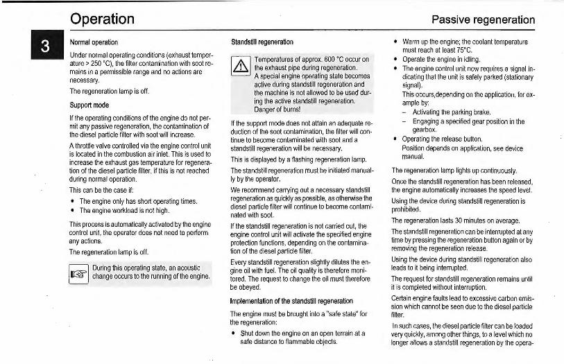
II Operation Nonnal operation
Under normal operating conditions (exhaust temper· ature > 250 'C), the filter contamination with soot remains in a permissible range and no actions are necessary.
The regeneration lamp is off.
Support mode
If the operating conditions of the engine do not per. mit any passive regeneration, the contamination of the diesel particle filter with soot will increase.
A throttle valve controlled via the engine control unit is located in the combustion air inlet. This is used to increase the exhaust gas temperature for regeneration of the diesel particle filter, if this is not reached during normal operation.
This can be the case if:
• The engine only has short operating times. • The engine workload is not high.
This process is automatically activated by the engine control unit, the operator does not need to perform any actions.
The regeneration lamp is off.
Q During this operating state, an acoustic EJ change occurs to the running of the engine.
Standstill regeneration
1/.\] Temperatures of approx. 600 'C occur on [9 the exhaust pipe during regeneration.
A special engine operating state becomes active during standstill regeneration and the machine is not allowed to be used during the active standstill regeneration. Danger of burns!
If the support mode does not attain an adequate reduction of the soot contamination, the fi lter will continue to become contaminated with soot and a standstill regeneration will be necessary.
This is displayed by a flashing re~eneration lamp.
The standstill regeneration must be initiated manually by the operator.
We recommend carrying out a necessary standstill regeneration as quickly as possible, as otherwise the diesel particle filter will continue to become contaminated with soot.
If the standsti ll regeneration is not carried out, the engine control unit will activate the specified engine protection functions, depending on the contamination of the diesel particle filter.
Every standstill regeneration slightly dilutes the engine oil with fuel. The oil quality is therefore monitored. The request to change the oil must therefore be obeyed.
Implementation of the standstill regeneration
The engine must be brought into a "safe state" for the regeneration:
• Shut down the engine on an open terrain at a safe distance to flammable objects.
Passive regeneration
• Warm up the engine; the coolant temperature must reach at least 75' C.
• Operate the engine in idling. • The engine control unit now requires a signal in
dicating that the unit is safely parked (stationary signal). This occurs,depending on the application, for example by: - Activating the parking brake. - Engaging a specified gear position in the
gearbox. • Operating the release button.
Position depends on application, see device manual.
The regeneration lamp lights up continuously.
Once the standstill regeneration has been released, the engine automatically increases the speed level.
Using the device during standstill regeneration is prohibited.
The regeneration lasts 30 minutes on average.
The standsti ll regeneration can be interrupted at any time by pressing the regeneration button again or by removing the regeneration release.
Using the device during standstill regeneration also leads to it being interrupted.
The request for standstill regeneration remains until it is completed without interruption.
Certain engine faults lead to excessive carbon emission which cannot be seen due to the diesel particle fil ter.
In such cases, the diesel particle filter can be loaded very quickly, among other things, to a level which no longer allows a standstill regeneration by the opera-

Passive regeneration
tor.
Very short intervals between two standstill regenerations (<10h) can be an indication of such a defect.
Please contact the DEUTZ service.
The regeneration lamp goes out when regeneration has been successfully completed.
If the standstill regeneration request is not observed and the DPF is overloaded to an impermissible level, then the filter can only be regenerated via the DEUTZ service.
Replacing the diesel particle filter
It may be necessary to replace the diesel particle filter after a high filter running time as non-combustible residues accumulate in the filter- so-called ash.
If the ash loading goes beyond a certain level, this will be indicated by the ash lamp.
The diesel particle filter needs to be replaced.
The machine can operate normally until the replacement is carried out by the service.
The time interval between two regeneration requests is shortened in proportion to the run time.
Please contact your DEUTZ partner
The contaminated diesel particle filter can be returned and replaced with a clean one in the DEUTZ exchange programme.
Operation
II
II Operation Passive regeneration
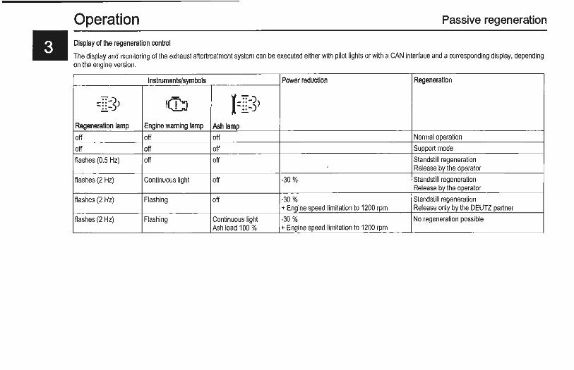
Display of the regeneration control
The display and monitoring of the exhaust aftertreatment system can be executed either with pilot lights or with a CAN interface and a corresponding display, depending on the engine version.
Instruments/symbols Power reduction Regeneration
_: : -)) -::-.) !(G) J-==-)) - ::-)
Regeneration lamp Engine warning lamp Ash lamp off off off Normal operation
off off off Support mode
fiashes (0.5 Hz) off off Standstill regeneration Release by the operator
fiashes (2 Hz) Continuous light off -30% Standstill regeneration Release by the operator
fiashes (2 Hz) Flashing off -30 % Standstill regeneration +Engine speed limitation to 1200 rpm Release only by the OEUTZ partner
fiashes (2 Hz) Flashing Continuous light -30% No regeneration possible Ash load 1 00 % +Engine speed limitation to 1200 rpm

Stopping process
I.{Sl Avoid switching off from full load (coking/ Li2J blockage of the remaining lubricating oil in
the turbocharger bearing housing). The lubricating oil supply of the turbocharger is then no longer guaranteed! This shortens the life of the turbocharger. Run the engine in low idling speed for approximately one minute after relieving the load.
• Move the key to position 0. P = gear position: park 0 = gear position: switch off engine 1 = gear position: Ignition on 2 =gear position: start engine
Lag time
JAl The control unit remains active for about eJ another 40 seconds to save the system
data (lag) and then switches off automatically.
Operation

II Operating media General
Modern diesel engines place very high demands on the lubricating oil to be used. The specific engine performances which have increased constantly over the last few years lead to an increased thermal load on the lubricating oil. The lubricating oil is also more exposed to contamination due to reduced oil comsumption and longer oil change intervals. For this reason it is necessary to observe the requirements and recommendations described in this operating manual in order not to shorten the life of the engine.
Lubricating oils always consist of a base oil and an additive package. The most important tasks of a lubricating oil (e.g. wear protection, corrosion protection, neutralisation of acids from combustion products, prevention of coke and soot deposits on the engine parts) are assumed by the additives. The properties of the base oil are also decisive for the quality of the product, e.g. with regard to thermal load capacity.
In principle, all engine oils of the same specification can be mixed. However, mixing of engine oils should be avoided because the worst properties of the mixture are always dominant.
The lubricating oils approved by DEUTZ have been thoroughly tested for all engine applications. The active ingredients they contain are compatible with each other. Therefore, the use of additives for lubricating oils is not permitted in DEUTZ engines.
The lubricating oil quality has a considerable influence on the life, performance and thus also on the costs-effectiveness of the engine. It basically applies that: The better the lubricating oil quality, the better these properties.
The lubricating oil viscosity describes the way the lu-
bricating oil flows, depending on the temperature. The lubricating oil viscosity only has a small influence and effect on the quality of the oil.
Synthetic lubricating oils are used increasingly and offer advantages. These lubricating oils have better temperature and oxidation stability as well as relatively low cold vicosity. Since some processes which are relevant for determining the lubricating oil change times are largely dependent on the oil quality (e.g. the infiltration of soot and other contamination), the oil change time for synthetic lubricating oils may not be increased in relation to the specifications on lubricating oil change intervals.
Biodegradable lubricating oils may be used in DEUTZ engines if they meet the requirements of this operating manual. ·
Quality
Lubricating oils are classified by DEUTZ according to their performance and quality class (DOC: DEUTZ Quality Class). Essentially, the following applies: the higher the quality class (DQC I, II, Ill, IV), the more effective/the better quality the lubricating oil is.
The DOC quality classes are still to be extended by the DOC-LA quality classes which include the modern, low-ash lubricating oils (LA = Low Ash).
Lubricating oils according to other comparable specifications can be used as long as they meet DEUTZ requirements. In regions in which none of these qualities are available, please contact your responsible DEUTZ partner.
or see www.deutz.com
Lubricating oil
http://wMY.deutz.oom
de \SERVICE \Betriebsstoffe und Addi-tive\Deutz Quality Class\DQC-Freigabeliste
en \SERVICE \Operating Liquids and Addi-tives\Oeutz Quality Class\OQC Release List
The choice of luricating oil essentially depends on the exhaust aftertreatment system.
The following lubricating oils are permissible for the engines in this operating manual:
Permissible quality class
DEUTZ Others
Engines with exhaust aftertreatment system
DOC IIIlA Please contact your DEUTZ part-
DOC IV LA ner
Engines without exhaust aftertreatment system
DQCII Please contact your DEUTZ part-
DQCIII ner
DOC III lA
OQCIV
DQC IVLA
For low-ash engine oils released according to the DOC system an appropriate reference is made in the oil release list.
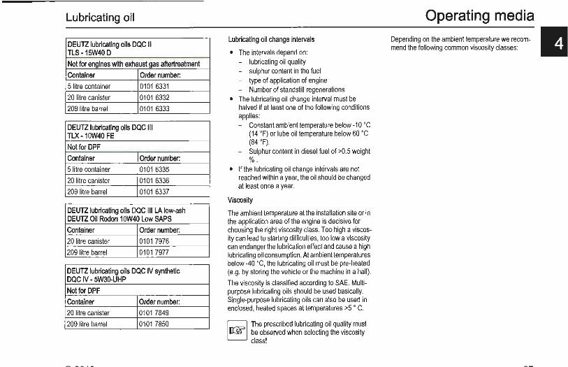
Lubricating oil
DEUTZ lubricating oils DQC II TLS -15W40 D
Not for engines with exhaust gas aftertreatment
Container Order number:
5 litre container 0101 6331
20 litre canister 0101 6332
209 litre barrel 0101 6333
DEUTZ lubricating oils DQC Ill TLX -10W40 FE
Not for DPF
Container Order number:
5 li tre container 0101 6335
20 litre canister 0101 6336
209 litre barrel 0101 6337
DEUTZ lubricating oils DQC Ill LA low-ash DEUTZ Oil Rodon 10W40 Low SAPS
Container Order number:
20 litre canister 0101 7976
209 litre barrel 0101 7977
DEUTZ lubricating oils DQC IV synthetic DQC IV - 5W30-UHP
Not for DPF
Container Order number:
20 litre canister 0101 7849
209 litre barrel 0101 7850
Lubricating oil change intervals
• The intervals depend on: - lubricating oil quality - sulphur content in the fuel - type of application of engine - Number of standstill regenerations
• The lubricating oil change interval must be halved if at least one of the following conditions applies: - Constant ambient temperature below -10 'C
(14 ' F) or lube oil temperature below 60 ' C (84 ' F).
- Sulphur content in diesel fuel of >0.5 weight %.
• If the lubricating oil change intervals are not reached within a year, the oil should be changed at least once a year.
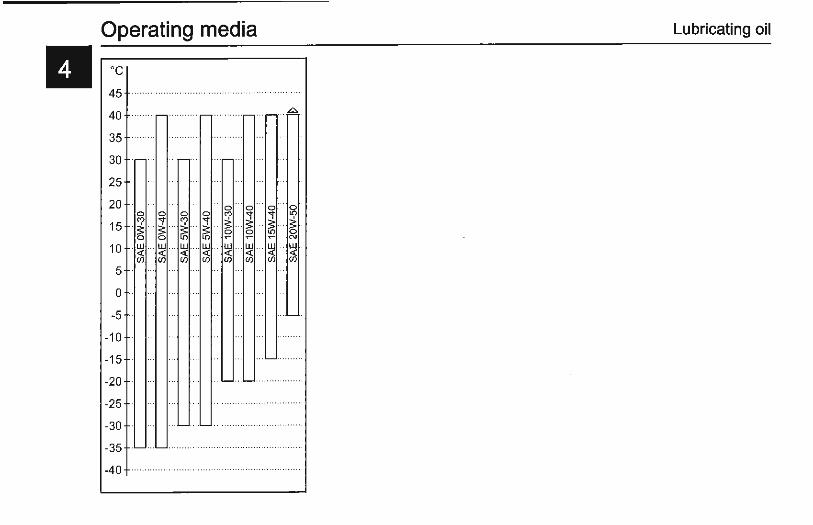
Viscosity
The ambient temperature at the installation site or in the application area of the engine is decisive for choosing the right viscosity class. Too high a viscosity can lead to starting difficulties, too low a viscosity can endanger the lubrication effect and cause a high lubricating oil consumption. At ambient temperatures below -40 'C, the lubricating oil must be pre-heated (e.g. by storing the vehicle or the machine in a hall).
The viscosity is classified according to SAE. Multipurpose lubricating oils should be used basically. Single-purpose lubricating oils can also be used in enclosed, heated spaces at temperatures >5 ' C.
~ The prescribed lubricating oil quality must EJ be observed when selecting the viscosity
class!
Operating media Depending on the ambient temperature we recom- II mend the following common viscosity classes:
Operating media Lubricating oil
II oc 45
40
35
30
25
20 0
"' 15 · ~ 0
... 0
.. 0 0
.. 0
0 0 0 "' ,. ,. l{)
··~ "' · ~ . ~ ~ .. ~ ... $: ... $: .. 0 0 l{) 0
0 l{) l{) ~ ~ ~ N
10 . UJ <( (/)
.. UJ . . . UJ ... . UJ .. . UJ .. UJ ... UJ ... UJ <( <( <( <( <( <( <( (/) (/) (/) (/) (/) (/) (/)
5
0
-5
-10
-15
-20
-25
-30
-35
-40
Fuel
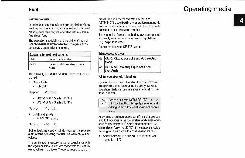
Pennissible fuels
In order to satisfy the exhaust gas legislation, diesel engines that are equipped with an exhaust aftertreatment system may only be operated with a sulphurfree diesel fuel.
The operational reliability and durability of the individual exhaust aftertreatment technologies cannot be assured upon failure to comply.
Exhaust aftertreatment systems
DPF Diesel particle filter
DOC Diesel oxidation catalytic con-verter
The following fuel specifications I standards are approved:
• Diesel fuels - EN 590
Sulphur <10 mg/kg
- ASTM D 975 Grade 1-D S15 - ASTM D 975 Grade 2-D S15
Sulphur <15 mg/kg
• Light heating oils - in EN 590 quality
Sulphur <10 mg/kg
If other fuels are used which do not meet the requirements of the operating manual, the warranty will be voided.
The certification measurements for compliance with the legal emission values are made with the test fuels specified in the laws. These correspond to the
diesel fuels in accordance with EN 590 and ASTM D 975 described in the operation manual. No emission values are guaranteed with the other fuels described in this operation manual.
The respective fuels prescribed by law must be used to comply with the national emission regulations (e.g. sulphur content).
Please contact your DEUTZ partner
http://\wlw.deutz.com
de \SERVICE\Betriebsstoffe und Additive\Kraft-stoffe
en \SERVICE\Operating Liquids and Addi-tives\Fuels
Winter operation with diesel fuel
Special demands are placed on the cold behaviour (temperature limit value of the filtrability) for winter operation. Suitable fuels are available at filling stations in winter.
l.tJ For engines with DCR® DEUTZ common L:i2J rail injection, the mixing of petroleum and
adding of extra low additives is not permissible.
At low ambient temperatures paraffin discharges can lead to blockages in the fuel system and cause operating faults. Below 0 'C ambient temperature use winter diesel (down to -20 'C) (fi lling stations provide this in good time before the cold season starts).
• Special diesel fuels can be used for arctic climates to -44 ' C.
Operating media
II

II Operating media General
1/,\l Never operate the engine without coolant, ~ even for a short time!
In liquid-cooled engines, the coolant must be conditioned and monitored, otheiWise the engine could be damaged by:
• corrosion • cavitation • freezing • overheating
Water quality
The right water quality is important for conditioning the coolant. Clear, clean water within the following analysis values should always be used:
Analysis values min max ASTM
ph value 6,5 8,5 01293 Chlorine (CI) [mgnJ . 100 0512
04327
Sulphate (S04) [mg/1] . 100 0 516 Total hardness [mmol/1) 3,56 D 1126 (CaC03) [mg/1) 356
rdGH) 20,0 [•e) 25,0 [•fH] 35,6
Specifications of the water quality are made by the local water board.
The water must be conditioned if it deviates from the analysis values.
• pH value too low: Addition of diluted sodium or potassium lye. Small trial mixtures are advisable.
• Total hardness too high: Mixing with softened water (pH neutralized condensate or water softened by ion exchanger).
• Chlorides and/or sulphates too high: Mixing with softened water (pH neutralized condensate or water softened by ion exchanger).
Cooling system oorrosion protection agent
1/,\l Health damaging nitrous amines form ~ when nitrite-based cooling system corro
sion protection agents are mixed with amine-based agents!
b] Cooling system corrosion protection agents EJ must be disposed of in an environmentally
friendly way. Observe the notes on the safety data sheet.
The conditioning of the coolant for liquid-cooled OEUTZ compact engines is performed by mixing an anti-freeze with corrosion protection inhibitors based on ethylene glycol into the water.
OEUTZ cooling system oorroslon protection agent
Container Order number:
5 litre container 01011490
20 litre canister 0101 6416
210 litre barrel 12211500
This cooling system corrosion protection agent is free from nitrite, amine and phosphate and is adapt-
Coolant
ed to the materials in our engines. Order from your DEUTZ partner.
Please contact your DEUTZ partner if the DEUTZ cooling system corrosion protection agent is not available.
http://www.deutz.oom
de \SERVICE\Betriebsstoffe und Additive\KOhlsystemschutz
en \SERVICE\Operating Liquids and Addi-tives\Cooling System Conditioner
The cooling system must be monitored regularly. This also includes checking the coolant system corrosion protection agent concentration in addition to checking the coolant level.
The cooling system corrosion protection agent concentration can be checked with conventional test instruments (e.g. refractometer).
Cooling system Water percent- Cold pro-oorrosion protec- age tection up lion agent percent- to age
min. 35% 65% -22 ·c
40 % 60% -2s·c
45 % 55% -35 ·c
max. 50% 50% -41'C
At temperatures below -41 ·c. please contact your responsible OEUTZ partner.
It is possible to use other cooling system corrosion protection agents (e.g. chemical corrosion protection agents) in exceptional cases. Consult your OEUTZ partner.
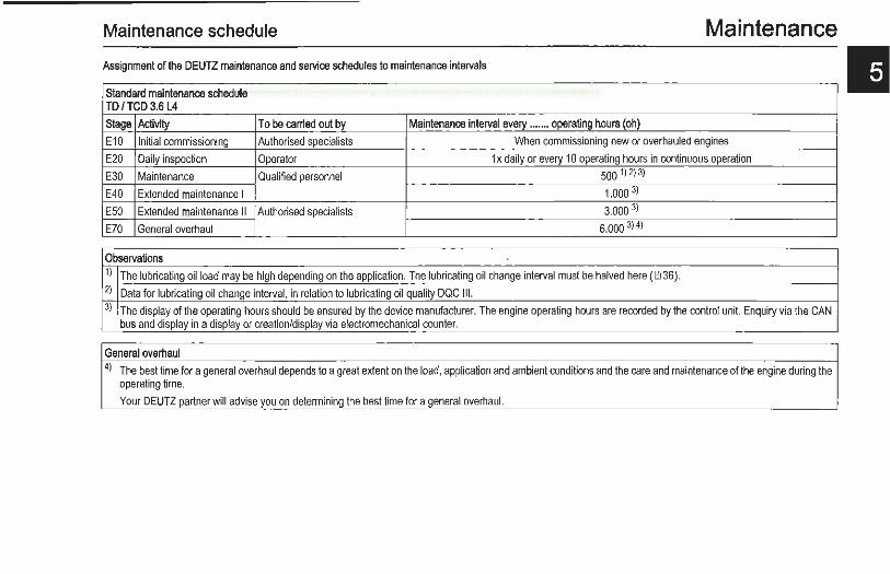
Maintenance schedule Maintenance Assignment of the DEUTZ maintenance and service schedules to maintenance intervals
Standard maintenance schedule TO f TCD 3.6 L4
Stage Activity To be carried out by Maintenance interval every ....... operating hours (oh)
E10 Initial commissioning Authorised specialists When commissioning new or overhauled engines
E20 Daily inspection Operator 1 x daily or every 10 operating hours in continuous operation
E30 Maintenance Qualified personnel 500 1) 2) 3)
E40 Extended maintenance I 1.000 3)
E50 Extended maintenance II Authorised specialists 3.000 3)
E70 General overhaul 6.000 3) 4>
Observations 1) The lubricating oil load may be high depending on the application. The lubricating oil change interval must be halved here (00 36). 2) Data for lubricating oil change interval, in relation to lubricating oil quality DQC Ill. 3) The display of the operating hours should be ensured by the device manufacturer. The engine operating hours are recorded by the control unit. Enquiry via the CAN
bus and display in a display or creation/display via electromechanical counter.
General overhaul 4l The best time for a general overhaul depends to a great extent on the load, application and ambient conditions and the care and maintenance of the engine during the
operating time.
Your DEUTZ partner will advise you on determining the best time for a general overhaul.

Maintenance Maintenance schedule
II M''"""""' m""'"' Stage Activity Measure Page E10 The measures are listed in chapter 3. ~24
E20 Check Lubricating oil level (if necessary top up) 0044
Coolant level (top up if necessary) ~25
Engine tightness (visual inspection for leaks)
Exhaust system including exhaust aftertreatment components for leaks 00 20
Suction air filter/dry air filter (maintain in accordance with maintenance indicator) 00 53
Emptying of the water tank in the fuel pre-filter &1 48
E30 Check V-belts ~ 55
Coolant (additive concentration) 0049
Intake air pipes for damage
Replace Lubricating oil filter/insert (every time the lubricating oil is changed) IM 5
Lubricating oil An lubricating oil application/change strategy adapted optimally to the individual engine application 00 36/IM 4 type can be created, for example, with the DEUTZ oil diagnosis. Ask your DEUTZ partner.
E40 Check Charge air cooler entry area (drain lube oil/condensate)
Battery and cable connectors llb56
Cold starting device
Engine mounting (tighten, replace if damaged when necessary)
Fastenings, hose unions I clips (renew if damaged)
V-rib belt and tensioning pulley 00 54
Replace Fuel filter cartridge IM 7
Filter insert for the fuel pre-filter. If the warning system responds (lamp/horn), the water trap bowl must be emptied 1MB immediately.
Dry air filter 00 53
V-belts 00 55
E50 Replace V-rib belt and tensioning pulley 00 54

Maintenance schedule Maintenance
Stage Activity Measure
annually Check Engine monitor, warning system Maintenance only to be carried out by authorised service personnel
Replace Fuel pre-fil ter
Every 2 Replace Dry air filter years Coolant
Status Change Diesel particle filter, the required exchange is displayed by the ash lamp or via an electronic display, depending on dependent the engine version (see DEUTZ exchange programme 1!1 32).
Maintenance wot1< outside the DEUTZ maintenance and service schedules
' If the water level warning system (lamp/siren) responds, the fuel pre-filter must be emptied immediately.
Maintenance profile
A self-adhesive maintenance diagram is delivered with every engine. It should be stuck in a well visible location on the engine or equipment.
Order number: 0312 3911 (TD/TCD 3.6 L4)
Page
~48
1!1 53
IMOIM 9
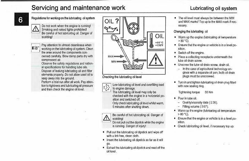
II Servicing and maintenance work Regulations for working on the lubricating oil system
IAl Do not work when the engine is running! [9 Smoking and naked lights prohibited!
Be careful of hot lubricating oil. Danger of scalding!
r::;:::;;:] Pay attention to utmost cleanliness when EJ working on the lubricating oil system. Clean
the area around the components concerned carefully. Blow damp parts dry with compressed air. Observe the safety regulations and national specifications for handling lube oils. Dispose of leaking lubricating oil and filter elements properly. Do not allow used oil to seep away into the ground. Perform a trial run after all work. Pay attention to tightness and lubricating oil pressure and then check the engine oil level.
Checking the lubricating oil level
~ Low lubricating oil level and overfilling lead ~ to engine damage.
The lubricating oil level may only be checked with the engine in a horizontal position and switched off. Only check lubricating oil level whilst warm, 5 minutes after shutting down.
W Be careful of hot lubricating oil. Danger of [9 scalding!
Do not pull out the dipstick while the engine is running. Danger of injury!
• Pull out the lubricating oil dipstick and wipe off with a lint-free, clean cloth.
• Insert the lubricating oil dipstick as far as it will go.
• Extract the lubricating oil dipstick and read off the oil level.
Lubricating oil system
• The oil level must always be between the MIN and MAX marks! Top up to the MAX mark if necessary.
Changing the lubricating oil
• Warm up the engine (lubricating oil temperature > ao ·c).
• Ensure that the engine or vehicle is in a level position.
• Switch off the engine. • Place a collecting receptacle underneath the
lube oil drain screw. • Unscrew the lube oil drain screw, drain oil.
- In the case of agricultural technology engines with a separate oil pan, both oil drain plugs must be unscrewed.
• Turn in and tighten lubricating oil drain plug fitted with new sealing ring.
Tightening torque 55 Nm
• Pour in lube oil. - Quality/viscosity data (00 36). - Filling volume (00 67).
• Warm up the engine (lubricating oil temperature > ao ·c).
• Ensure that the engine or vehicle is in a level position.
• Check lubricating oil level, if necessary top up.
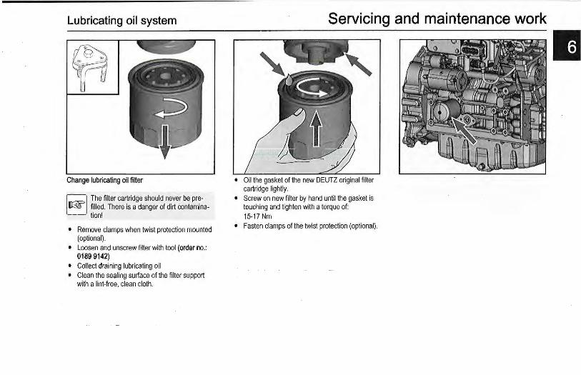
Lubricating oil system
Change lubricating oil filter
Q The filter cartridge should never be preEJ filled. There is a danger of dirt contamina
tion!
• Remove clamps when twist protection mounted (optional).
• Loosen and unscrew filter with tool (order no.: 0189 9142)
• Collect draining lubricating oil • Clean the sealing surface of the filter support
with a lint-free, clean cloth.
Servicing and maintenance work
• Oil the gasket of the new DEUTZ original fi lter cartridge lightly.
• Screw on new filter by hand until the gasket is touching and tighten with a torque of: 15-17 Nm
• Fasten clamps of the twist protection (optional).
II

II Servicing and maintenance work Specifications when working on the fuel system
Engine must be switched off! Smoking and naked lights p~ohibited! No injection/high pressure p1pes may be disconnected while the engine is running. Caution when handling hot fuel! Pay attention to utmost cleanliness when refuelling and working on the fuel system. Clean the respective affected parts carefully. Blow damp areas dry with compressed air. Observe the safety regulations and national specifications for handling fuels. Dispose of leaking fuel and filter elements properly. Do not allow fuel to seep away into the ground. After all work on the fuel system, the system should be vented, a trial run performed and the tightness checked. It will be necessary to vent the fuel system when commissioning for the first time, after maintenance work or if the tank has been run dry.
1.@ Additional venting of the fuel system by a 5 Li2J minute trial run at idle speed or on low load
is absolutely essential. Pay attention to utmost cleanliness due to the high production accuracy of the system! The fuel system must be tight and closed. Make a visual inspection for leaks/damage in the system.
1.@ Clean and dry the engine and engine comLi2J partment thoroughly before beginning
work. Areas of the engine compartment from which dirt could be loosened must be covered with a fresh, clean foil. Work on the fuel system may only be carried out in an absolutely clean environment. Contamination of the air such as dirt, dust, moisture etc. must be avoided.
Fuel system

Fuel system
Change the fuel filter cartridge
~ The filter cartridge should never be preE._] filled. There is a danger of dirt contamina
tion!
• Remove clamps when twist protection mounted (optional).
• Loosen and unscrew filter with tool (order no.: 0189 9142)
• Catch any escaping fuel. • Clean the sealing surface of the filter support
with a lint-free, clean cloth.
Servicing and maintenance work
• Oil the gasket of the new DEUTZ original filter cartridge lightly.
• Screw on new filter by hand until the gasket is touching and tighten with a torque of: 10-12Nm
• Fasten clamps of the twist protection (optional). • Vent the fuel system.
II
II Servicing and maintenance work
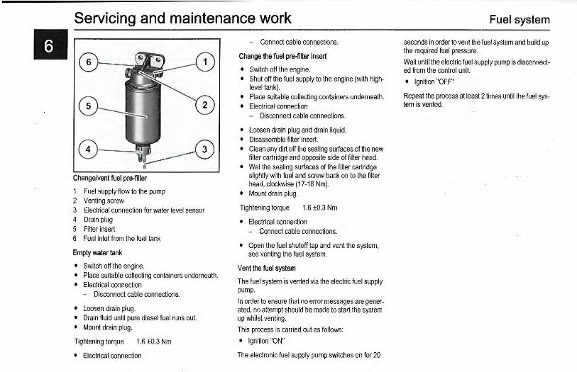
Change/vent fuel pre-filter
1 Fuel supply flow to the pump 2 Venting screw 3 Electrical connection for water level sensor 4 Drain plug 5 Filter insert 6 Fuel inlet from the fuel tank
Empty water tank
• Switch off the engine. • Place suitable collecting containers underneath. • Electrical connection
- Disconnect cable connections.
• Loosen drain plug. • Drain fluid until pure diesel fuel runs out. • Mount drain plug.
Tightening torque 1.6 ±0.3 Nm
• Electrical connection
- Connect cable connections.
Change the fuel pre-filter insert
• Switch off the engine. • Shut off the fuel supply to the engine (with high
level tank). • Place suitable collecting containers underneath. • Electrical connection
- Disconnect cable connections.
• Loosen drain plug and drain liquid. • Disassemble filter insert. • Clean any dirt off the sealing surfaces of the new
filter cartridge and opposite side of filter head. • Wet the sealing surfaces of the filter cartridge
slightly with fuel and screw back on to the filter head, clockwise (17-18 Nm).
• Mount drain plug.
Tightening torque 1.6 ±0.3 Nm
• Electrical connection - Connect cable connections.
• Open the fuel shutoff tap and vent the system, see venting the fuel system.
Vent the fuel system
The fuel system is vented via the electric fuel supply pump.
In order to ensure that no error messages are generated, no attempt should be made to start the system up whilst venting.
This process is carried out as follows:
• Ignition "ON"
The electronic fuel supply pump switches on for 20
Fuel system
seconds in order to vent the fuel system and build up the required fuel pressure.
Wait until the electric fuel supply pump is disconnected from the control unit.
• Ignition "OFF"
Repeat the process at least 2 times until the fuel system is vented.
Cooling system
Specifications when working on the cooling system
lA] Danger of scalding from hot coolant! ~ Cooling system under pressure! Only open
the cap when cool! The coolant must have a prescribed concentration of cooling system corrosion protection agent! Observe safety regulations and national specifications when handling cooling media. Observe the manufacturer's specifications for an external cooler. Dispose of leaking liquids properly and do not allow them to seep into the ground. Order coolant corrosion protection agent from your DEUTZ partner. Never operate the engine without coolant, even for a short time!
Checking the coolant level with an external cooler
• Fill in new coolant and vent the system according to the specifications of the cooling system manufacturer.
• Open the cooling system cap (1) carefully. • The coolant level must always be between the
MIN and MAX marks of the compensation tank! Fill up to the MAX mark if necessary.
Servicing and maintenance work
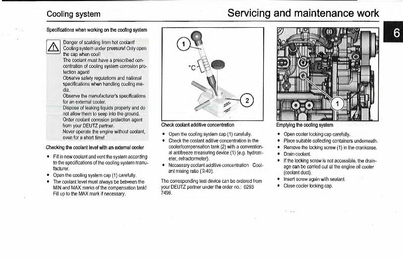
Check coolant additive concentration
• Open the cooling system cap (1) carefully. • Check the coolant aditive concentration in the
cooler/compensation tank (2) with a conventional antifreeze measuring device (1) (e.g. hydrometer, refractormeter).
• Necessary coolant additive concentration Cool-ant mixing ratio (lil40).
The corresponding test device can be ordered from your DEUTZ partner under the order no.: 0293 7499.
Emptying the cooling system
• Open cooler locking cap carefully. • Place suitable collecting containers underneath. • Remove the locking screw (1) in the crankcase. • Drain coolant. • If the locking screw is not accessible, the drain
age can be carried out at the engine oil cooler (coolant duct).
• Insert screw again with sealant. • Close cooler locking cap.
II
II Servicing and maintenance work
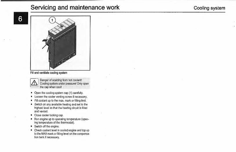
Fill and ventilate cooling system
IJ.\l Danger of scalding from hot coolant! [9 Cooling system under pressure! Only open
the cap when cool!
• Open the cooling system cap ( 1) carefully. • Loosen the cooler venting screw if necessary. • Fill coolant up to the max. mark or filling limit. • Switch on any available heating and set to the
highest level so that the heating circuit is filled and vented.
• Close cooler locking cap. • Run engine up to operating temperature (open
ing temperature of the thermostat). • Switch off the engine. • Check coolant level in cooled engine and top up
to the MAX mark or filling level on the compensation tank if necessary.
Cooling system
Engine cleaning
Cleaning work
!.ttl For all cleaning work, make sure that no ~ parts are damaged (e.g. bent cooler mesh).
Cover electrical/electronic parts and connections to clean the engine (e.g. control units, generator, solenoid valves etc.). Do not aim the water/steam jet directly at them. Allow engine to warm up.
IAl Only carry out cleaning work on the engine leJ when it is not running!
Remove the engine cover and cooling air cover if available and remount after cleaning.
General
The following causes of soiling make it necessary to clean the engine:
• High dust content in the air. • Chaff and chopped straw in the area of the en-
gine. • Coolant leaks • Lubricating oil leakage • Fuelleaks
Because of the different application conditions, cleaning depends on the degree of dirt contamination.
Cleaning with compressed air
• Blow dirt off or out. Always blow out the cooler and cooling fins from the exhaust air side to the fresh air side.
Servicing and maintenance work Cleaning with cold cleaner
• Spray the engine with cold cleaner and leave it for about 10 minutes to take effect.
• Spray the engine clean with a high pressure water jet.
• Warm up the engine so that the water residues evaporate.
Cleaning with a high pressure cleaner
• Clean the engine with a steam jet (maximum spray pressure 60 bar, maximum steam temperature 90 ·c. distance at least 1m).
• Warm up the engine so that the water residues evaporate.
• Always clean the cooler and cooling fins from the exhaust air side to the fresh air side.
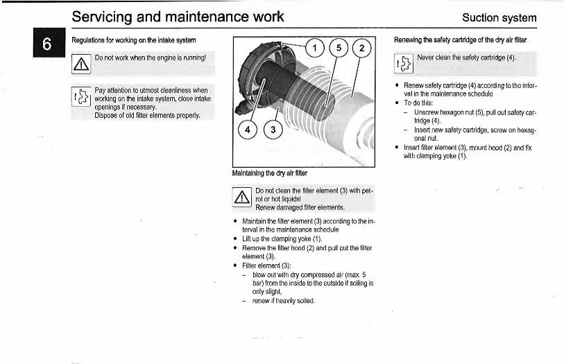
II Servicing and maintenance work Regulations for working on the intake system
I J1\ I Do not work when the engine is running!
~.ttl Pay attention to utmost cleanliness when LJ2:J working on the intake system, close intake
openings if necessary. Dispose of old filter elements properly.
Maintaining the dry air filter
W Do not clean the filter element (3) wi th petlej rol or hot liquids!
Renew damaged filter elements.
• Maintain the filter element (3) according to the interval in the maintenance schedule
• Lift up the clamping yoke (1 ). • Remove the fi lter hood (2) and pull out the filter
element (3) . • Fil ter element (3):
- blow out with dry compressed air (max. 5 bar) from the inside to the outside if soiling is only slight,
- renew if heavily soiled.
Suction system
Renewing the safety cartridge of the dry air filter
I ! 2} I Never clean the safely cartridge ( 4 ).
• Renew safety cartridge (4) according to the interval in the maintenance schedule
• To do this: - Unscrew hexagon nut (5), pull out safety car
tridge (4) . - Insert new safety cartridge, screw on hexag
onal nut. • Insert fi lter element (3), mount hood (2) and fix
with clamping yoke (1).
Suction system
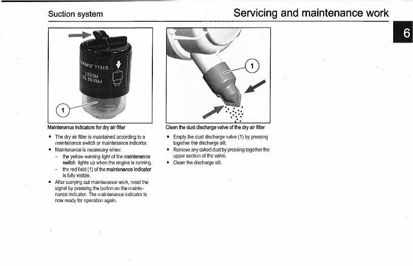
Maintenance indicators for dry air filter
• The dry air filter is maintained according to a maintenance switch or maintenance indicator.
• Maintenance is necessary when: - the yellow warning light of the maintenance
switch lights up when the engine is running. - the red field ( 1) of the maintenance indicator
is fully visible. • After carrying out maintenance work, reset the
signal by pressing the button on the maintenance indicator. The maintenance indicator is now ready for operation again.
Servicing and maintenance work
Clean the dust discharge valve of the dry air filter
• Empty the dust discharge valve (1) by pressing together the discharge slit.
• Remove any caked dust by pressing together the upper section of the valve.
• Clean the discharge slit.
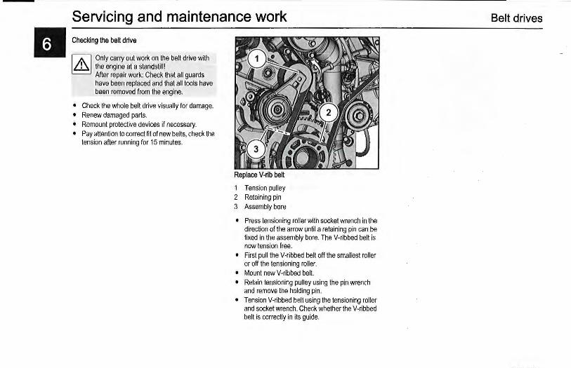
II Servicing and maintenance work Checking the belt drive
1/.\1 Only carry out work on the belt drive with ~ the engine at a standstill!
After repair work: Check that all guards have been replaced and that all tools have been removed from the engine.
• Check the whole belt drive visually for damage. • Renew damaged parts. • Remount protective devices if necessary. • Pay attention to correct fit of new belts, check the
tension after running for 15 minutes.
Replace V-rib belt
1 Tension pulley 2 Retaining pin 3 Assembly bore
• Press tensioning roller with socket wrench in the direction of the arrow until a retaining pin can be fixed in the assembly bore. The V-ribbed belt is now tension free.
• First pull the V-ribbed belt off the smallest roller or off the tensioning roller.
• Mount new V-ribbed belt. • Retain tensioning pulley using the pin wrench
and remove the holding pin. • Tension V-ribbed belt using the tensioning roller
and socket wrench. Check whether the V-ribbed belt is correctly in its guide.
Belt drives
Belt drives
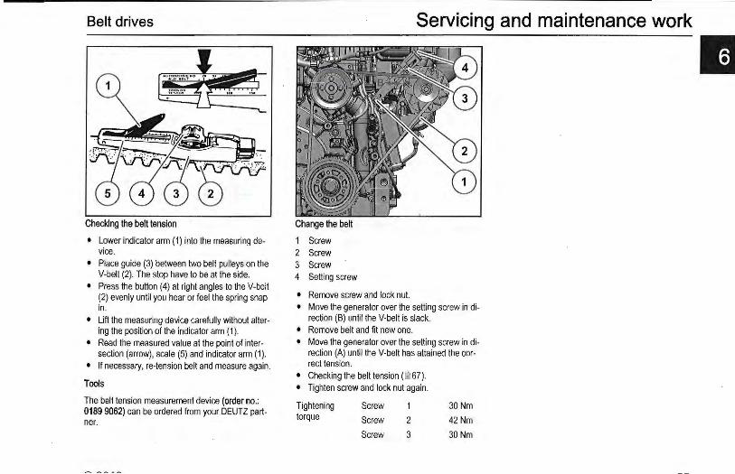
Checking the belt tension
• Lower indicator arm (1) into the measuring device.
• Place guide (3) between two belt pulleys on the V-belt (2). The stop have to be at the side.
• Press the button (4) at right angles to the V-belt (2) evenly until you hear or feel the spring snap in.
• Lift the measuring device carefully without altering the position of the indicator arm (1 ).
• Read the measured value at the point of intersection (arrow), scale (5) and indicator arm (1).
• If necessary, re-tension belt and measure again.
Tools
The belt tension measurement device (order no.: 0189 9062) can be ordered from your DEUTZ partner.
Servicing and maintenance work
Change the belt
1 Screw 2 Screw 3 Screw 4 Setting screw
• Remove screw and lock nut. • Move the generator over the setting screw in di
rection (B) until the V-belt is slack. • Remove belt and fit new one. • Move the generator over the setting screw in di
rection (A) until the V-belt has attained the correel tension.
• Checking the belt tension(~ 67). • Tighten screw and lock nut again.
Tightening torque
Screw
Screw
Screw
2
3
30 Nm
42 Nm
30 Nm

II Servicing and maintenance work Regulations for working on the electrical system
rA;l Do not touch the voltage conducting parts, l.eJ faulty warning lamps should be immediate
ly replaced.
1.8 Pay attention to correct polarity of the conL.i2J nections.
Cover electrical/electronic parts and connections to clean the engine (e.g. control units, generator, solenoid valves etc.). Do not aim the water/steam jet directly at them. Allow engine to warm up.
Battery
Touching a lead against the frame to check whether it is live must not, under any circumstances, be carried out. For electrical welding work, the ground terminal of the welding gear must be clamped directly to the part being welded. Three-phase current generator: Never disconnect the cables between battery, generator and regulator while the engine is running.
1.8 Electronically stored data could be lost if L.i2J the battery is disconnected.
Keep battery clean and dry. Make sure the battery is fitted correctly and securely. Dispose of old batteries in an environmentally friendly way.
rA;l Danger of explosion! The gases emitted by l.eJ the battery are explosive!
Fire, sparks, smoking and naked lights are prohibited! Danger of acid burns! Wear protective gloves and glasses! Avoid contact with skin and clothing! Danger of short circuit! Do not rest tools on the battery!
Checking the voltage
• Check the battery voltage with a standard voltmeter. The voltage gives information about the charge status.
Battery Charge status (Volt)
12Volt 12-14,4
24 Volt 24-28,4
Check acid level
• Unscrew caps. • Note the manufacturer's specifications concern
ing the liquid level. The liquid should normally be 10-15 mm above the top edge of the plate or reach up to any available control device.
• Only use distilled water to top up the battery. • Screw in caps.
Electrical system
Check acid density
• Unscrew caps. • Measure the electrolyte density of individual cells
with a commercial hydrometer. Hydrometer reading indicates battery's state of charge. The acid temperature when measuring should be 20 'C if possible.
• Check the acid level before recharging. • Screw in caps.
Acid density (kg/ Q Charge Measure
Normal Tropical status
1,28 1,23 good none
1,20 1,12 half charge
1,12 1,08 empty charge
Electrical system
Removing the battery
• Always disconnect the minus pole first when removing the battery. Otherwise there is a danger of short-circuit!
• Remove the fastenings and take out the battery.
Charging the battery
• Unscrew caps. • Charge the battery with a conventional battery
charger. Observe the manufacturer specifications!
• Screw in caps.
Installing the battery
• Insert new or charged battery and attach the fastenings.
• Clean the terminals and battery poles with fine emery paper.
• Connect the plus pole first and then the minus pole. Otherwise there is a danger of short-circuit! Make sure the terminals have good contact. Tighten clamp bolts hand-tight.
• Grease the assembled terminals with an acidfree, acid-resistant grease.
Servicing and maintenance work
II

Faults Fault table
Faults Causes Measures
Engine does not start or is difficult to Not disconnected (if possible) Check coupling start Fuel tank empty Tanks
Electric fuel supply pump defective Check
Fuel suction pipe blocked Check
Below starting limit temperature Check
Cold starting device Check/replace
Wrong SAE viscosity class of the engine lubricating oil Change the lubricating oil
Fuel quality does not comply with operating manual Change the fuel
Battery defective or discharged Check battery
Cable connection to starter loose or oxidized Check cable connections
Starter defective or pinion does not engage Check starter
Air filter clogged I turbocharger defective Check/replace
Air in fuel system Vent fuel system
Compression pressure too low Check compression pressure
Exhaust gas backpressure too high Check
Injection line leaks Check injection line
Engine does not start and diagnostic Engine electronics prevents starting Check error according to error code and lamp flashes eliminate error if necessary
Engine starts, but runs irregularly or Exhaust gas backpressure too high Check fails Compression pressure too low Check compression pressure
Cold starting device Check/replace
Air in fuel system Vent
Fuel filter contaminated Clean
Fuel quality does not comply with operating manual Change the fuel
Injector defective Change
Injection line leaks Check injection line
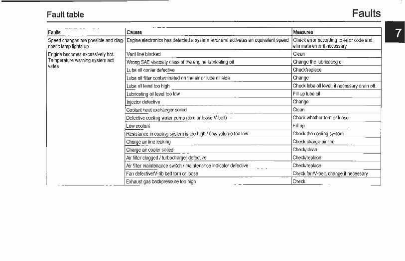
Fault table Faults
II Faults Causes Measures
Speed changes are possible and diag- Engine electronics has detected a system error and activates an equivalent speed Check error according to error code and nostic lamp lights up eliminate error if necessary
Engine becomes excessively hot. Vent line blocked Clean Temperature warning system acti- Wrong SAE viscosity class of the engine lubricating oil Change the lubricating oil vales
Lube oil cooler defective Check/replace
Lube oil filter contaminated on the air or lube oil side Change
Lube oil level too high Check lube oil level, if necessary drain off.
Lubricating oil level too low Fill up lube oil
Injector defective Change
Coolant heat exchanger soiled Clean
Defective cooling water pump (torn or loose V-belt) Check whether torn or loose
Low coolant Fill up
Resistance in cooling system is too high I flow volume too low Check the cooling system
Charge air line leaking Check charge air line
Charge air cooler soiled Check/clean
Air filter clogged I turbocharger defective Check/replace
Air filter maintenance switch I maintenance indicator defective Check/replace
Fan defectiveN-rib belt torn or loose Check fanN-belt, change if necessary
Exhaust gas backpressure too high Check
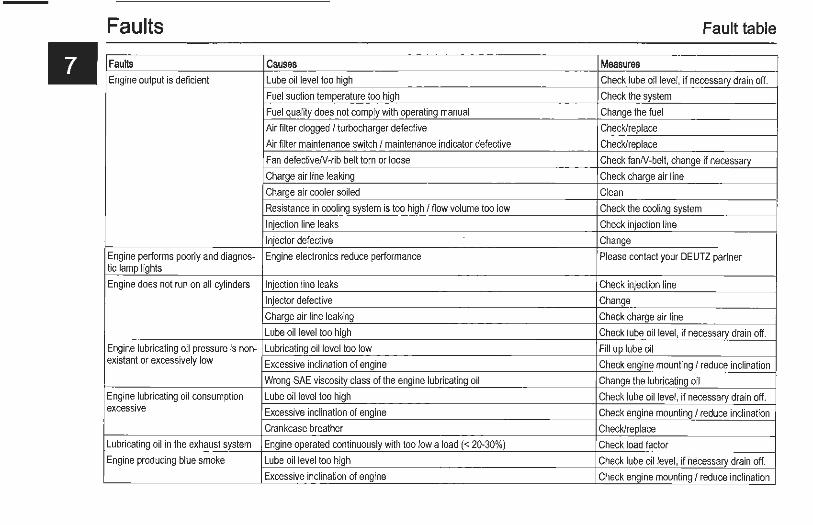
Faults Fault table
II Faults Causes Measures Engine output is deficient Lube oil level too high Check lube oil level, if necessary drain off.
Fuel suction temperature too high Check the system
Fuel quality does not comply with operating manual Change the fuel
Air filter clogged I turbocharger defective Check/replace
Air filter maintenance switch I maintenance indicator defective Check/replace
Fan defectiveN-rib belt torn or loose Check !anN-belt, change if necessary
Charge air line leaking Check charge air line
Charge air cooler soiled Clean
Resistance in cooling system is too high I flow volume too low Check the cooling system
Injection line leaks Check injection line
Injector defective Change
Engine performs poorly and diagnos- Engine electronics reduce performance Please contact your DEUTZ partner tic lamp lights
Engine does not run on all cylinders Injection line leaks Check injection line
Injector defective Change
Charge air line leaking Check charge air line
Lube oil level too high Check lube oil level, if necessary drain off.
Engine lubricating oil pressure is non- Lubricating oil level too low Fill up lube oil existant or excessively low Excessive inclination of engine Check engine mounting I reduce inclination
Wrong SAE viscosity class of the engine lubricating oil Change the lubricating oil
Engine lubricating oil consumption Lube oil level too high Check lube oil level, if necessary drain off. excessive Excessive inclination of engine Check engine mounting I reduce inclination
Crankcase breather Check/replace
Lubricating oil in the exhaust system Engine operated continuously with too low a load(< 20-30%) Check load factor Engine producing blue smoke Lube oil level too high Check lube oil level, if necessary drain off.
Excessive inclination of engine Check engine mounting I reduce inclination
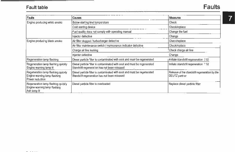
Fault table Faults
II Faults Causes Measures Engine producing white smoke Below starting limit temperature Check
Cold starting device Check/replace
Fuel quality does not comply with operating manual Change the fuel
Injector defective Change
Engine producing black smoke Air filter clogged I turbocharger defective Check/replace
Air filter maintenance switch I maintenance indicator defective Check/replace
Charge air line leaking Check charge air line
Injector defective Change
Regeneration lamp flashing Diesel particle filter is contaminated with soot and must be regenerated Initiate standstill regeneration ~ 32
Regeneration lamp flashing quickly Diesel particle filter is contaminated with soot and must be regenerated Initiate standstill regeneration 00 32 Engine warning lamp lit Standstill regeneration has not been released
Regeneration lamp flashing quickly Diesel particle filter is contaminated with soot and must be regenerated Release of the standstill regeneration by the Engine warning lamp flashing Standstill regeneration has not been released DEUTZ partner Power reduction
Regeneration lamp flashing quickly Diesel particle filter is overloaded Replace diesel particle filter Engine warning lamp flashing Ash lamp lit

Faults
Engine protection function of the electronic engine control
1 Diagnosis button
2 Error lamp
3 Electronic engine control (EMR)
Q The error lamp goes out when all the errors EJ have been eliminated. For some errors, it is
necessary to switch off the ignition, wait 30 s and only then switch back on the ignition. The appropriate monitoring functions are switched off when a sensor fails. Only the sensor failure is documented in the error memory.
Depending on the design of the monitoring functions, the electronic engine control can protect the engine in certain problematical situations by monitoring important limit values during operation and checking the correct function of the system components.
Depending on the seriousness of a recognised fault, the engine can continue to operate with limitations, during which the error lamp lights up continuously or indicates a serious system error by flashing. In this case, the engine should be switched off as soon as safely possible.
Error lamp
The error lamp is located in the vehicle drive stand.
The error lamp can release the following signals:
• Function test - Ignition on, error lamp lights up for approx. 2
seconds and then goes out. - Check the error lamp if there is no reaction
after switching on the ignition. • The lamp does not light
- After the lamp test an extinguished lamp indicates an error-free and trouble-free operating state within the scope of the control possibility.
• Continuous light Error in system. - Operation continued with restrictions.
The engine must be checked by a DEUTZ partner. If a lamp lights steadily a monitored measuring variable (e.g. coolant temperature, lubricating oil pressure) has left the permissible value range. Depending on the fault, the engine power may be reduced by the electronic engine control to protect the engine.
• Flashing Serious error in system.
Engine management
- Switch off prompt for the operator. Attention: Failure to do so will lead to loss of guarantee!
- The engine has reached switch-off condition. - Engine forced to run with power reduction to
cool the engine, with automatic shutdown if necessary.
- The switch-off process has been accomplished.
- There may be a start lock after engine stop. - The start lock is deactivated by turning off the
system with the ignition key for approx. 30s. - optionally the power reduction can be by
passed, the automatic switch-off delayed or a start lock bypassed with the override key on the instrument panel to avoid critical situations. This brief deactivation of the engine protection functions is logged in the control unit.
Please contact your DEUTZ-partner in case of malfunctions and sare parts inquiries. Our specially trained personnel will ensure fast, professional repairs using original DEUTZ spare parts in case of damage.
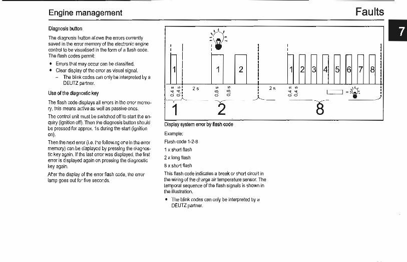
Engine management
Diagnosis button
The diagnosis button allows the errors currently saved in the error memory of the electronic engine control to be visualised in the form of a flash code. The flash codes permit:
• Errors that may occur can be dassified. • Clear display of the error as visual signal.
- The blink codes can only be interpreted by a DEUTZ partner.
Use of the diagnostic key
The flash code displays all errors in the error memory, this means active as well as passive ones.
The control unit must be switched off to start the enquiry (ignition off). Then the diagnosis button should be pressed for approx. 1s during the start (ignition on).
Then the next error (i.e. the following one in the error memory) can be displayed by pressing the diagnostic key again. If the last error was displayed, the first error is displayed again on pressing the diagnostic key again.
After the display of the error flash code, the error lamp goes out for five seconds.
~CiJ-. -I I I I I f- I f--
I 1 1 I l
Ill 111 1 2s Ill Ill
~~ ~ .. : a) a)
0 0 0 0~ ll 2 Display system error by flash code
Example:
Flash code 1-2-8
1 x short flash
2 x long flash
8 x short flash
I - I
I
2 I I I I
I I I
This flash code indicates a break or short circuit in the wiring of the charge air temperature sensor. The temporal sequence of the flash signals is shown in the illustration.
• The blink codes can only be interpreted by a DEUTZ partner.
Faults
II I I I
f- r- - - r- r- r- r- I I 1 2 3 4 5 6 7 8 I I
2s Ill (J)
c:::=J = =~ I
<t <t I
Oci I I
.-/
8
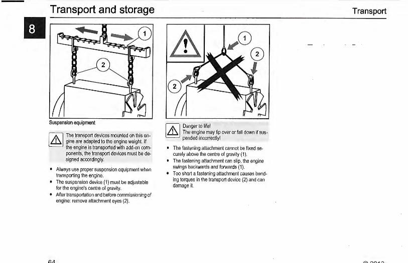
II Transport and storage
Suspension equipment
rAJ The transport devices mounted on this en~ gine are adapted to the engine weight. If
the engine is transported wi th add-on components, the transport devices must be designed accordingly.
• Always use proper suspension equipment when transporting the engine.
• The suspension device (1) must be adjustable for the engine's centre of gravity.
• After transportation and before commissioning of engine: remove attachment eyes (2) .
rAJ Danger to life! ~ The engine may tip over or fall down if sus
pended incorrectly!
• The fastening attachment cannot be fixed securely above the centre of gravity ( 1).
• The fastening attachment can slip, the engine swings backwards and forwards (1 ).
• Too short a fastening attachment causes bending torques in the transport device (2) and can damage it.
Transport
Engine corrosion protection
General
Engines contain the following types of corrosion protection:
• Interior corrosion protection • Exterior corrosion protection
b] Your OEUTZ partner has' the right corro~ sian protection agent for r our needs.
The following measures for corrosion protection after taking the engine out of operation meet the requirements for 12 months corrosion pmtection.
The following corrosion protection work may only be carried out by persons familiar with it and instructed in the potential dangers.
If these measures are deviated from by exposing the corrosion-protected engines or parts to unfavourable conditions (installation outdoors or storage in damp, badly aired places) or damage to the corrosion protection layer, a shorter corrosion protection duration is to be expected.
The engine corrosion protection should be checked about every 3 months by opening the covers. If corrosion is detected, the corrosion protection should be renewed.
At the end of the corrosion protection work the crank drive may no longer be turned so that the corrosion protection agent in the bearings, bearing liners and cylinder liners is not scraped off.
Before operating a corrosion protected engine, the corrosion protection must be removed.
Interior corrosion protection
• Interior corrosion protection is always provided by wetting of the walls with the implemented cor-
rosion protection agent in a corrosion protection run of the engine.
• The corrosion protection run can be performed once to protect the different systems:
Fuel system
Close the fuel/tank/supply line to the engine so that the system is protected against dirt and dust. Protect the electronics against moisture and corrosion.
• Fill the fuel tank with a mixture of: - 90 % distilled fuel - 10% corrosion protection oil.
• Perform a corrosion protection run with no load for at least 5 minutes.
Lubricating oil system
• Drain lubricating oil from warm engine. • Thoroughly clean lube oil tray, cylinder head with
rocker arms, valves, valve springs with diesel fuel or cleaning agent.
• Fill engine with TIT AN EM 2020 OEUTZ (SAE 20W-20) preservation oil and carry out corrosion protection run (together with corrosion protection run for fuel system), warm up the engine to approx. 60 'C, duration at least 5 minutes so that all components of the lubricating oil system are wet,
or
all accessible components are wet with preservation oil and pump approx. 60 'C warm preservation oil through the engine with a separate pump until all bearings and bearing liners are wet.
Transport and storage Cooling system
• Depending on the series the engines are equipped with cooling air, cooling oil or cooling fluid system (cooling water with cooling system protection agent).
• Cooling air system, see the Exterior corrosion protection section.
• In engines of the oil-cooled series the circulating lubricating oil serves simultaneously for cooling. The cooling chambers are protected automatically against corrosion with the lube oil system.
• If a coolant with corrosion protection properties is poured into liquid-cooled engines, no further action is necessary after draining.
• If not, the coolant must be drained and, to ensure the formation of a covering layer on the inside surfaces of the cooling system, a corrosion protection run performed with a mixture of: - 95 % treated water - 5 % corrosion protection agent
• The duration of the corrosion protection run and the concentration of the corrosion protection agent are specified by the manufacturer of the corrosion protection agent.
• Then drain the coolant.
Air intake pipes
• Spray ANTICORIT VCI UNI 0 40 corrosion protection oil or TIT AN EM 2020 OEUTZ (SAE 20W-20) preservation oil into the intake air pipe.
Exterior corrosion protection
• The engine must be cleaned thoroughly with a cleaning agent before exterior corrosion protection. Any signs of corrosion and damage to the paintwork must be removed.
II Transport and storage Bare exterior surfaces and parts
• Coat or spray all bare exterior parts and surfaces (e.g. flywheel, flange faces) with corrosion protection agent.
Rubber parts
• Rubber parts (e.g. muffs) which are not painted over must be rubbed down with talcum powder.
Belt drive
• Remove V-belts and V-rib belts and store packed.
• Spray V-belt pulleys and tension rollers with corrosion protection agent.
Engine openings
• All engine openings must be fitted with air-tight, water -tight covers to delay the vapourisation process of the corrosion protection agents.
• With installed air compressor, the suction and pressure connection must be sealed by a cap.
• Air should be excluded to avoid ventilation of the engine (chimney effect) for the suction from an air supply pipe.
Storage and packaging
• After being protected against corrosion, the engine must be stored in a dry, ventilated hall and suitably covered.
• The cover must be placed loosely over the engine so that the air can circulate around it to prevent condensation from forming. Use a desiccant if necessary.
Removal of corrosion protection
• The corrosion protection must be removed from the corrosion protected engine before starting.
• The packaging and all covers over the closed openings must be removed.
• Any corrosion deposits and paint damage should be remedied.
Fuel system
If there is a mixture of diesel fuel/corrosion protection oil in the fuel tank, drain it.
• Connect fuel/tank/supply line to the engine. Pay attention to cleanliness.
• Fill the fuel tank and fuel system with the proper fuel.
Lubricating oil system
• Unscrew the lube oil drain screw, drain oil. • Fill the engine with lubricating oil via the lubricat
ing oil filler neck.
Coolant system
• If the implemented corrosion protection agent is compatible with the intended cooling system protection agent, this can be filled directly into the coolant system as specified.
• If it is uncertain whether the implemented corrosion protection agent is compatible with the cooling system protection agent, the cooling system should be purged with fresh water for about 15 minutes before filling.
Removal of exterior corrosion protection
• All areas and components coated with corrosion protection agent must be washed off with dis-
Engine ~orrosion protection
tilled fuel or a suitable cleaning agent. • Wash out grooves of V-belt pulleys if necessary. • Mount V-belts or V-rib belts as specified. • Fill with coolant.
Corrosion protection agent I cleaning agent
Please ask your DEUTZ partner for reference products for the corrosion protection agents/cleaning agents to be used· which meet DEUTZ requirements.
or see www.deutz.c:om
http://www.deutz.oom
de \SERVICE \Betriebsstoffe und Addi-tive\Motorkonservierung
en \SERVICE\Operating Liquids and Addi-tives\Engine Corrosion Protection
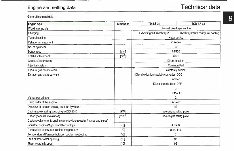
Engine and setting data Technical data General technical data
Engine type Dimension TD 3.6 L4 I TCD3.6 L4
Working principle Four-stroke diesel engine
Charging Exhaust gas turbocharger I Turbocharger with charge air cooling
Type of cooling water-cooled
Cylinder arrangement in series
No. of cylinders 4
Bore/stroke [mm] 98/120
Total displacement [cm3] 3621
Combustion process Direct injection
Injection system Common Rail
Exhaust gas recirculation externally cooled
Exhaust gas aftertreatment Diesel oxidation catalytic converter DOC
and/or
Diesel particle filter DPF
or
without
Valves per cylinder 2
Firing order of the engine 1-3-4-2
Direction of rotation looking onto the flywheel left
Engine power rating according to ISO 3046 [kW] see engine rating plate
Speed (nominal revolutions) [min'1] see engine rating plate
Coolant volume (only engine content without cooler I hoses and pipes)
Industrial engines/Agricultural technology '= [I] 4,6/4,6
Permissible continuous coolant temperature [·q max. 110
Temperature difference between coolant inleVoutlet [.C] 8
Start of thermostat opening [•q 88 Thermostat fully open ("C] 95

Technical data Engine and setting data
II Engine type Dimension TD 3.6 L4 l TCD3.6 L4 Lubricating oil change volume (with filter) "[I) 8'
Lube oil temperature in the lube oil tray, maximum rCJ 125 Lubricating oil pressure minimum (low idle, engine warm) [kPa/bar] 80/0,8
Permissible maximum combustion air temperature after charge air cooler ['C) 50
V-belt tension Pre-tensioning/Re-tensioning V-belts AVX (width: 13 mm) [N) 650±50/400±50
V -rib belt tensioning Automatic tensioning spring-loaded clamping roller
Weight without cooling system according to DIN 70020-A "' [kg) 350
' specified lubricating oil filling volumes apply for standard versions. In engines which deviate from the standard, for example different lubricating oil pans/dipstick variants and/or special inclined versions, the lubricating oil volume may vary. The lubricating oil dipstick mark is always decisive.

Tools
Tool ordering
The special tools described in this chapter can be ordered from:
Please contact your DEUTZ partner
Torx tool
Order number:
0189 9092
The Torx screw system is used in engines in this series among other things. This system was introduced for a number of reasons:
• Excellent accessibility • High force transmission when loosening and
tightening • Slipping or breaking of the key and risk of injury
are practically excluded.
Technical data
V-belttension measuring Instrument
Order number:
0189 9062
Measuring instrument for checking the specified Vbelt tensions.

II Technical data
Special wrench for loosening exchangeable filters
Order number:
0189 9142
For loosening changeable filters.
Refractometer
Order number:
0293 7499
The following operating media can be evaluated with this test device:
• Coolant • Battery acid • AdBiue®
Tools

DEUTZ Operating Fluids
DEUTZ Oil Rod on 1 OW40 DEUTZ Oel TLX-10W40FE DEUTZ Cooling System low SAPS (DQC 111-10 LA) (DQC 111-10) Conditioner
5L - 5L 0101 6335 5L 01011490 20 L 0101 7976 20 L 0101 6336 20 L 0101 6416
209 L 0101 7977 209 L 0101 6337 210 L 12211500
DEUTZ Oel DQC4-5W30-UHP (DQC IV-10)
5L -20 L 0101 7849
209 L 0101 7850

The engine company.
DEUTZAG
Information Systems Sales & Service
OttostraBe 1
D-51149 Koln
Germany
Phone: +49 (o) 2 21-8 22-o
+49 (o) 2 21-8 22-35 25
Fax:
E-Mail:
Internet: www.deutz.com
Printed in Germany
© oS/2013
All rights reserved
Order number: 0312 4633 en
Original operating instructions
t07l"l