OPERATION AND MAINTENANCE MANUAL · Basic therminology, methodology UNI EN 12100-2 (April 2005):...
74
OPERATION AND MAINTENANCE MANUAL ADHESIVE TAPES SLITTER-REWINDER TAG 330 Ed. 0 – Rev. 0 — March 2012 ORIGINAL INSTRUCTIONS PREPARED IN ACCORDANCE WITH THE 2006/42/EEC DIRECTIVE – ANNEX I - SECTION 1.7.4
Transcript of OPERATION AND MAINTENANCE MANUAL · Basic therminology, methodology UNI EN 12100-2 (April 2005):...

OPERATION AND MAINTENANCE
MANUAL
ADHESIVE TAPES SLITTER-REWINDER
TAG 330
Ed. 0 – Rev. 0 — March 2012
ORIGINAL INSTRUCTIONS
PREPARED IN ACCORDANCE WITH THE 2006/42/EEC DIRECTIVE – ANNEX I - SECTION 1.7.4

OPERATION MANUAL AUTOMATIC SLITTER REWINDER TAG330
Many thanks for your choice a machine manufactured by (NOME CLIENTE)
This machine has been designed and manufactured using the best actual technologies andprocedures to assure its best reliability in its lifetime and maximum safety to operators.
For proper and safe machine utilization, is essential reading carefully and observe as indic-ated in this manual.
All the documentation supplied with the machine – and especially this manual – should bepreserved for future reference.
Ed. 0 —Rev.0 – March 2012 - EN 2/74

OPERATION MANUAL AUTOMATIC SLITTER REWINDER TAG330
© 2012 (NOME CLIENTE) - All rights reserved
This publication or parts thereof may not be reproduced, stored, transmitted, transcribed
or translated in any language, common or computerized, in any form or by any means
electronic, mechanical, magnetic, optical, chemical, manual or other without the express written
consent by (NOME CLIENTE).
(NOME CLIENTE)provides assurance regarding the contents of this publication, with the
express prohibition on the use of this publication for any other purpose whatsoever, commercial,
practical, technical-scientific other than referred machine operation for which this publication
has been prepared.
The guarantee of the information correctness herein contained is provided on condition
that they are strictly observed, by the user of the machine, all requirements contained in this
documentation.
(NOME CLIENTE)also reserves the right to revise and change this publication without
prior communication to any person or organization.
The revised publications will be available on request to (NOME CLIENTE)
The original operation manual is written in Italian language.
Ed. 0 —Rev.0 – March 2012 - EN 3/74

OPERATION MANUAL AUTOMATIC SLITTER REWINDER TAG330
CONTENTS
SECTION 1 GENERAL INFORMATION 6 PREFACE.............................................................................................................................. 7
INTENDED USE............................................................................................................ 7MANUAL STORAGE....................................................................................................... 7ACCEPTANCE AND OPERATORS INSTRUCTION.................................................................8AUTHORIZED STAFF..................................................................................................... 8STANDARDS AND REFERENCE DOCUMENTATION............................................................. 8MACHINE LABELLING.................................................................................................... 9ATTACHMENTS............................................................................................................. 9
OVERVIEW..........................................................................................................................10TECHNICAL FEATURES......................................................................................................... 12
MACHINE LABELLING.................................................................................................. 12WEIGHTS.................................................................................................................. 12OVERALL DIMENSIONS................................................................................................12POWER SUPPLY......................................................................................................... 12AIR POWER............................................................................................................... 13OIL SUPPLY FOR HYDRAULIC CIRCUITS........................................................................ 13TECHNICAL FEATURES................................................................................................ 13OPERATING AND STORAGE ENVIRONMENTAL CONDITIONS.............................................13MACHINE AIRBORNE NOISE......................................................................................... 14
Information on noise dangers....................................................................... 14SAFETY SYSTEMS............................................................................................................... 16
EMERGENCY STOPS................................................................................................... 16ELECTRICAL SYSTEM PROTECTIONS............................................................................ 18PNEUMATIC SYSTEM PROTECTIONS............................................................................. 18HYDRAULIC SYSTEM PROTECTIONS............................................................................. 19MOVING COMPONENTS PROTECTIONS......................................................................... 19
Perimetric protections.................................................................................. 19Photocells / light barriers.............................................................................. 21Repairs, fixed protections, mobile protections.............................................. 23
MACHINE CONTROL CIRCUITS..................................................................................... 24MISUSE AND WARNINGS...................................................................................................... 26
OPERATIONS ON THE MACHINE................................................................................... 26CAUTIONS, WARNINGS TO OPERATORS, RESIDUAL RISKS..............................................27
SECTION 2 OPERATION MANUAL 29 INTENDED USE................................................................................................................... 30OPERATORS....................................................................................................................... 30
OPERATORS POSITION................................................................................................30Operators clothing and equipment............................................................... 30
CONTROLS......................................................................................................................... 31MAIN CONTROL PANEL.............................................................................................. 33CORE LOADER CONTROL REPEATER........................................................................... 41JUMBO ROLL UNWINDING ASS’Y CONTROL PANEL.........................................................42MACHINE START – STOP PANEL................................................................................... 43EMERGENCY ON TAPE DISCHARGER............................................................................ 43
Main power disconnector............................................................................. 44MACHINE OPERATION.......................................................................................................... 45
2.4 .1 PRELIMINARY CHECKS AT START UP.................................................................. 45MANUAL AND AUTOMATIC OPERATING MODE................................................................ 45NORMAL START UP AND STOP OF THE MACHINERY....................................................... 46INTENDED OPERATION CYCLE......................................................................................53RESETTING ON FAULT OR JAM.....................................................................................53
Ed. 0 —Rev.0 – March 2012 - EN 4/74

OPERATION MANUAL AUTOMATIC SLITTER REWINDER TAG330
RECOVERY AFTER AN EMERGENCY STOPPING..............................................................53
SECTION 3. TECHNICAL MANUAL 54 SHIPPING AND INSTALLATION...........................................................................................55
SHIPPING AND HANDLING........................................................................................... 55INSTALLATION............................................................................................................ 56
Flooring 56Lighting 56Machine Assembly....................................................................................... 56Stability requirements for the machine......................................................... 56Machine positioning..................................................................................... 56Covered area............................................................................................... 56
CONTROLS POSITIONING............................................................................................ 57MACHINE FIXING AND LEVELLING.................................................................................57MACHINE POWER SUPPLIES........................................................................................ 57
Electric power supply................................................................................... 57Air power...................................................................................................... 59
AUDITS FOR THE COMMISSIONING............................................................................... 59MAINTENANCE.................................................................................................................... 61
OILS AND GREASES USED IN MAINTENANCE................................................................. 61PREVENTIVE MAINTENANCE ON THE MACHINE.............................................................. 66
General Checks........................................................................................... 66Machine cleaning......................................................................................... 66Regular maintenance and lubrication........................................................... 66
ELECTRIC SYSTEM..................................................................................................... 66SAFETY AND CONTROL / SIGNAL DEVICES EFFICIENCY CHECK.......................................67EXTRAORDINARY MAINTENANCE................................................................................. 67SPARE PARTS............................................................................................................ 68
SETTINGS........................................................................................................................... 69JUMBO ROLL LOADING – UNWINDING AREA.................................................................. 69CARDBOARD CORES LOADING..................................................................................... 71MEASURE EXCHANGE.......................................................................................... 73
DECOMMISSIONING............................................................................................................. 75
Ed. 0 —Rev.0 – March 2012 - EN 5/74

OPERATION MANUAL AUTOMATIC SLITTER REWINDER TAG330
SECTION 1 GENERAL INFORMATION
Ed. 0 —Rev.0 – March 2012 - EN 6/74

OPERATION MANUAL AUTOMATIC SLITTER REWINDER TAG330
PREFACEThe proper and safe machine operation is assured only when used in accordance with the
contents of this manual and, in general, the documentation accompanying the machine itself; soit is essential to carefully read and retain all related documentation.
Although the machine is equipped with active and passive safety devices, cannot beavoided all the risks due to its misuse.
You must ensure that all the operators have fully understood the operational rules; (NOMECLIENTE)is not responsible for damages to persons or properties resulting from machine im-proper utilization.
Do not remove or deteriorate labels, marks and warning placed onto machine parts. Ifneeded, ask (NOME CLIENTE)for new items to restore them.
(NOME CLIENTE) disclaims any and all liability for failure to follow safety and preventionrules described in the various sections of this manual and for damages due to improper use.
Any machine changes must be previously authorized by PPM Industries SpA.
All work on the machine (maintenance, adjustments, repair, cleaning) must be performed byproperly trained staff ad as specified herein.
INTENDED USE
This machine has been designed and built for the subdivision of jumbo rolls into strips ofpredetermined width and winding tape on cardboard cores. Upon reaching the preset length inmeters, the slitter cuts the tape.
In particular, this manual refers to machine having the characteristics described in Section1.3.
WARNING! Any use of the machine different from described hereinis forbidden.
WARNING! The used materials must comply with those specified inSection 1.3 of this manual.
MANUAL STORAGE
This operational manual is part of the machine and must be retained for future reference.
We recommend:
Keep the manual in an accessible and familiar to all operators place, protected frommoisture and heat, away from direct sun rays.
Use the manual in such a way so to not damage the contents all or in part. Do notremove, tear or modify for any reason any part of this manual.
In case of machine sale or transfer to another person, this manual and its attachments mustbe delivered intact to the new user.
WARNING! Before machine operation, please, read carefully this operationmanual. Any user of this machine must be properly informed about the relev-ant parts of this operation manual regarding the operations to be performed.
Ed. 0 —Rev.0 – March 2012 - EN 7/74

OPERATION MANUAL AUTOMATIC SLITTER REWINDER TAG330
ACCEPTANCE AND OPERATORS INSTRUCTION
The machines built by (NOME CLIENTE) are subject to an acceptance test during whichthe operational and dimensional characteristics, processing time, etc.; concurrently with this testis performed the training to the operators.
That acceptance test is confirmed by a report containing:
Machine identification data;
Tests and audits performed;
Notes, attachments, specifications etc.
WARNING! The machine cannot be used until has been successful testedand the operators training completed.
AUTHORIZED STAFF
Repair and maintenance of this machine must be performed only by competent personnel,b y (NOME CLIENTE)or authorized by PPM Industries SpA. Information for personnel to becontacted for any assistance can be obtained directly from PPM Industries SpA.
STANDARDS AND REFERENCE DOCUMENTATION
The reference documentation for machine designing and manufacturing by (NOME CLI-ENTE)is the following:
UNI EN 12100-1 (April 2005): Machinery safety. Fundamental concepts, general prin-ciples for design. Basic therminology, methodology
UNI EN 12100-2 (April 2005): Machinery safety. Fundamental concepts, general prin-ciples for design. Technical Principles
Directive 2006/42/EEC of the European Parliament and Council of 17 May 2006 on ma-chinery and amending Directive 95/16/EEc (recast).
Directive 2006/95/EEC amending Directive 96/68/EEC (and 73/23/EEC) electrical equip-ment for use within certain voltage limits.
Directive 2007-4/108/EEC of the European Parliament and the Council of 15 December2004 on the approximation of the laws of the Member States relating to electromagneticcompatibility.
Italian Government D.Lgs n. 194 of 6 November 2007: Implementation of Directive2004/108/EEC on the harmonization of the laws of the Member States relating to elec-tromagnetic compatibility and repealing the Directive 98/336/EEC.
According to Directive 2004/108/EEC (Electromagnetic Compatibility) the machine isdefined as a fixed installation.
MACHINE LABELLING
The machine is equipped with a label containing the data shown in Fig. 1:
(NOME CLIENTE);references; CE marking; Model; Type; Serial number; Manufacturing Year.
Ed. 0 —Rev.0 – March 2012 - EN 8/74

OPERATION MANUAL AUTOMATIC SLITTER REWINDER TAG330
.
MACHINE TYPEMODEL
MANUFACTURING YEAR SERIAL NUMBER
WEIGHT KgPOWER SOURCE / PHASES 380V / 3 PH + N
FREQUENCY 50 Hz ELECTRIC RATED POWER Kw
HYDRAULIC RATED PRESSURE 50 barPNEUMATIC RATED PRSSURE 0,6 MPa
Fig. 1 – Machine Labelling
The machine features contained in the label are given in Section 1.3.
WARNING! It is recommended not to remove labels on the ma-chine; the labels must be kept firmly fixed, intact and in excellentreadability condition.
WARNING! The data contained in machine labelling must becommunicated for any need of assistance or spare parts.
ATTACHMENTS
The following attachments are integral parts of this manual:
CE Conformity Declaration; Electric drawings; Machine layout; Machine schemes and drawings.
OVERVIEWThe machine has been designed and built for adhesive tapes winding operation onto card-
board cores and their cutting at a predetermined length after rewinding.
The machine consists of the following main parts:
Ed. 0 —Rev.0 – March 2012 - EN 9/74

OPERATION MANUAL AUTOMATIC SLITTER REWINDER TAG330
Fig. 2 – Machine General View - Cardboard Core loading and tapes unloading
Fig. 3 – Machine General View – Rewinding and cutting area
Ed. 0 —Rev.0 – March 2012 - EN 10/74

OPERATION MANUAL AUTOMATIC SLITTER REWINDER TAG330
Fig. 4– Machine General view – Main rolls loading and unwinding area
Fig. 5 – Machine General View – Core Loader area
Ed. 0 —Rev.0 – March 2012 - EN 11/74

OPERATION MANUAL AUTOMATIC SLITTER REWINDER TAG330
TECHNICAL FEATURES
MACHINE LABELLING
MANUFACTURER DATA AND ADDRESS(NOME CLIENTE)
MODEL; AUTOMATIC CUTTER- REWINDER
TYPE; TAG 330
SERIAL NUMBER;
YEAR
WEIGHTS
The table below contains the weight of the elements of which the handling mode was de-scribed in paragraph 3.1.1.
MACHINE WEIGHT [kg]
ANY MACHINE PART N.D.
OVERALL DIMENSIONS
Machine overall dimensions, contained in the attached layout, are:
Length = meters about;
Width = meters about;
Height = meters about.
POWER SUPPLY
The characteristics of the power supply are the following:
VOLTAGE 380 V
AUXILIARIES VOLTAGE D.C. 24 V
FREQUENCY 50 Hz
NUMBER OF PHASES 3PH + PE
Below is the plate located onto the electrical main control panel.
Ed. 0 —Rev.0 – March 2012 - EN 12/74

OPERATION MANUAL AUTOMATIC SLITTER REWINDER TAG330
(Here the main control panel image)
Fig. 6 – Main Control panel plate
AIR POWER
OPERATING PRESSURE 6 bar
AIR CHARACTERISTICS DRY, OIL AND DUST FREE
OIL SUPPLY FOR HYDRAULIC CIRCUITS
To hydraulic circuit pump must be supplied oil having the following characteristics:
OPERATING PRESSURE 50 bar
OIL QUANTITY IN THE TANK UNIT 180 litres
OIL CHARACTERISTICS Mobil DTE 24
TECHNICAL FEATURES
ADHESIVE TAPE WORKABLE TYPES Self adhesive film of special material
MAIN ROLL MAX. DIAMETER 850 mm
MAIN ROLL MAX. WEIGHT 900 kg
MAX. MAIN ROLL WIDTH 1,500 mm
WARNING! The machine must be used only for splitting a mainroll made in special material into several tapes rewound onto card-board cores having proper dimension.
(NOME CLIENTE)disclaims any liability for any malfunction ordamage arising from utilization of materials having characteristicsdifferent from those described in this manual.
OPERATING AND STORAGE ENVIRONMENTAL CONDITIONS The machine was designed and built to operate in a closed and dry environment.
The operating environmental conditions are:
Temperature: + 5 ~ +40 °C;
Humidity: 30 ~ 95 % without condensation.
WARNING! For proper operation of the electrical equipment,the room temperature should be between +5 and 40 °C and thehumidity must not exceed 50% at a max temperature of 40 °C(relative humidity higher could be allowed at lower temperatures).
If the environmental conditions are particularly critical, it is recommended to provide aproper air conditioning system to restore the humidity and the temperature within acceptablelimits.
Ed. 0 —Rev.0 – March 2012 - EN 13/74

OPERATION MANUAL AUTOMATIC SLITTER REWINDER TAG330
The machine has no special requirements for storage, provided that the storage is in aclosed and dry room; this condition must also be ensured during all delivery and shipping time.
WARNING! For proper operation of the electrical equipment, themachine storage must be at a temperature between -25°C and+55°C and, only for a short time not exceeding 24 hours, at +70°C.
If the machine is stored in a dusty environment, we suggest to:
Remove from the machine all the liquids;
Treat the in sight metal parts with anti rust;
Cover the machine with a cloth.
MACHINE AIRBORNE NOISE
The equivalent continuous acoustic pressure level weighed (A) emitted by the machine,measured in the points as for Fig. 7 is equal to:
Point 1 (Main rolls loading and unwinding area): dB(A);
Point 2 ( tapes rewinding and cutting area): dB(A);
Point 3 (cardboard cores feeder): dB(A);
Point 4 (main control position): dB(A);
The measures were taken onto the machine during its normal work cycle.
The max acoustic pressure is equal to dB(A) and was detected at the measuring point N° 4.
Measurements made in accordance with the directions of the Machinery Directive2006/42/EEC and of ISO 3746.
Information on noise dangers
The airborne noise emission level is highly variable depending on the specific character-istics of each machine configuration.
The listed airborne noise emission levels do not assure safe exposure levels for the work -ers.
The exposure levels of the worker are obviously related to machine emission levels; how-ever other factors also influence the levels of workers exposure.
The factors include the exposure duration, the environmental characteristics, and thepresence of other machinery.
The machine emission levels allow the user to carry out an assessment of the hazardsdue to airborne noise. .
In case of noisy work (or other resonances) perform the following operations:
The 8 h daily normalized exposure value Lex, as for Directive 2003/10/EEC is evalu-ated in:
a. Lower exposure value: Lex,8h = 80 dB(A) and LpC.peak = 135 dB(C): If this value exceedsthe lower action value, you should use personal protective equipment for the hearing.
Ed. 0 —Rev.0 – March 2012 - EN 14/74

OPERATION MANUAL AUTOMATIC SLITTER REWINDER TAG330
b. Higher exposure value: Lex,8h = 85 dB(A) and LpC.peak = 137 dB(C): If this value exceedsthe higher action value, you must prepare and implement a program of technical/organisationalmeasures to reduce noise exposure.
c. Limit exposure value: Lex,8h = 87 dB(A) and LpC.peak = 140 dB(C): If this value exceeds theexposure limit, you should immediately activate measures to reduce noise levels below the limitexposure value, identify the reason for the over-exposure and improve prevention and protec-tion measures to avoid the recurrence.
WARNING! Measure the daily noise exposure in the workplacewith a sound level meter and if possible enable the necessarycountermeasures.
In case where the operators may experience excessive machinenoise, check for the failure presence or if maintenance operations(see also Section 3.2).
WARNING! This machine issues high noise levels. We recom-mend the user to provide suitable protection equipment to the op-erators.
WARNING! In case where the operators may experience excess-ive machine noise, check for the failure presence or if maintenanceoperations (see also Section 3.2).
Ed. 0 —Rev.0 – March 2012 - EN 15/74

OPERATION MANUAL AUTOMATIC SLITTER REWINDER TAG330
SAFETY SYSTEMSThe machine is equipped with active and passive safety systems: The set of those systems
allow preventing dangers to persons working onto the machine or existing in its vicinity.
WARNING! The machine is designed to meet the ergonomic prin-ciples allowing the operator to work in conditions that minimize theefforts, the movements, the frequency of cyclical actions, etc. in or-der to avoid as possible discomfort, stress, physical or psychicaldamages.
WARNING! The presence of safety systems does not exempt theoperators to work with utmost care to avoid actions that might en-danger their safety or the machine integrity. Particularly, the oper-ator must not entangle with moving machine parts.
WARNING! Personal protections such as goggles, headsets,earplugs, safety shoes and gloves must be worn and used by staffwhen operating conditions and laws require their use.
WARNING! Is strictly forbidden to alter, modify or try to escape inany way the machine safety systems.
EMERGENCY STOPS
The machine is equipped with red emergency stop auto latching type buttons, and their re-leases do not restart the machine.
The position of these devices is shown in Fig. 8, 9, 10 and 11.
Fig. 8 – Emergency Stop – Main Control Panel
Ed. 0 —Rev.0 – March 2012 - EN 16/74

OPERATION MANUAL AUTOMATIC SLITTER REWINDER TAG330
Fig. 9 – Emergency Stop – Cardboard cores loading
Fig.10 – Emergency Stop – Unwinding equipment
Fig. 11 – Emergency Stop – Tapes discharging equipment
Ed. 0 —Rev.0 – March 2012 - EN 17/74

OPERATION MANUAL AUTOMATIC SLITTER REWINDER TAG330
To restore machine operation, it is necessary to operate as described in section 2.4.6.
ELECTRICAL SYSTEM PROTECTIONS
The electrical system has been designed and built to protect the operators from electricshock hazards and the whole machinery from eventual overheating or other abnormal danger-ous condition.
All machine metallic parts are connected to the equipotential protection circuit to avoiddanger arising from failure of any insulation.
The electrical equipment components comply with the Directive 2001/108/EEC, asamended and integrated, and are installed according to manufacturer’s instructions.
Moreover, all the electrical devices coming into contact with operators – buttons, indicators,etc. – are impermeable to penetration by liquids or vapours that could cause short circuits ordamage to insulation.
There are also over-current protections to prevent any failure able to cause overheating orhazardous conditions.
Removing power supply when the machine is running does not immediately stop the ma-chine parts in the position where they are due to large inertia forces involved, so before ap-proaching and/or service on the machine, you must wait for the full stop.
WARNING! So that the electrical system protections are effective, it isnecessary that the machine is connected to an external power supplywith over current protection device, against insulation failures and withan equipotential protection circuit, as described in section 3.1.5.1.
PNEUMATIC SYSTEM PROTECTIONS
All the components of the pneumatic system are designed for a maximum operating pres-sure far greater than the maximum working pressure of the system itself. The pneumatic circuitpipes are still placed in a not easily damageable position, and their possible failure would notcause significant risk being the pressure low (about 6 bars).
WARNING! Is strictly forbidden to change the settings of the maxpressure relief valve protecting the machine pneumatic system. Im-proper regulation of these devices may cause malfunction or failuresof pneumatic system components and endanger the workers safety.
Ed. 0 —Rev.0 – March 2012 - EN 18/74

OPERATION MANUAL AUTOMATIC SLITTER REWINDER TAG330
Air inlet and pressure regolator and gauge view
HYDRAULIC SYSTEM PROTECTIONS
All the components of the hydraulic system are designed for a maximum operating pressurefar greater than the maximum working pressure of the system itself. The hydraulic system pipesare placed at points not easily damageable and their eventual braking would not cause signific-ant risks being the pipes located in machine areas not normally accessible by the operators dur-ing the machine normal operation.
WARNING! Is strictly forbidden to change the settings of the max pres-sure relief valve protecting the machine hydraulic system. Improper reg-ulation of these devices may cause malfunction or failures of hydraulicsystem components and endanger the workers safety.
MOVING COMPONENTS PROTECTIONS
There are risks of collision, cutting, entanglement, crushing, shearing and dragging withvarious transmission and cutting elements involved in the machine work process.
Perimetric protections
The dangerous elements of main reels unwinding and tapes rewinding over the cardboardcores are protected by perimetric interlocked repairs with their openings controlled by safety mi-cro switches, photo sensors or light barriers.
Upon these devices activation, the protection devices intervene stopping the machine.
In particular, to allow access inside the perimeter protection of unwinding area, are presenttwo half - casings with guide fixed to the ground for opening and closing with locking hinges.
Semi-casings opening is monitored by two photo sensors with reflector activated when thecasing opens more than 10 cm from locking position, stopping the machine.
After the stop, is necessary to perform the normal restarting procedure.
Fig. 11 – Unwinding zone
Ed. 0 —Rev.0 – March 2012 - EN 19/74

OPERATION MANUAL AUTOMATIC SLITTER REWINDER TAG330
Fig. 12 – Rewinding zone
Fig. 13 – Manhole
Ed. 0 —Rev.0 – March 2012 - EN 20/74

OPERATION MANUAL AUTOMATIC SLITTER REWINDER TAG330
Fig. 14 – Cardboard cores feeder
Photocells / light barriers
The photoelectric sensor monitoring the carriage movement from the cardboard cores load-ing / tapes discharging area, starts working and stops the machine if an operator or foreign bodyenters its range.
In this case, the machine does not stop immediately, but enters into a safe mode stoppingany other operation except the completion of the actual tape rewinding cycle. After this opera-tion, the machine stops completely and for restarting, you must perform the recovery procedure.
Fig. 15 – Rewinding zone
Between the unwinding and rewinding zone, there is a manhole allowing the operator toenter into the area to perform maintenance or adjustments to the cylinders zone
Entering in the manhole is monitored by light barriers onto both sides, stopping eventuallythe machine.
Ed. 0 —Rev.0 – March 2012 - EN 21/74

OPERATION MANUAL AUTOMATIC SLITTER REWINDER TAG330
Fig. 16 – Manhole
In the cores loading area and translation carriage to rewinding area is installed a protectionfixed to the floor provided with a light barrier and a reset button. When the operator enters thisposition with the machine running, activates the immediate machine stopping. At the end of theoperations, the operator must press the reset button to unlock the light barriers and perform therecovery procedure to restart normal work cycle.
Fig. 17 – Cardboard cores feeder
Repairs, fixed protections, mobile protections
On some dangerous machine parts (for example: transmission belts, motors, main reelrollers, etc) there are protections to limit the risks with moving elements and the attainment ofaccidental hazardous areas.
The fixed protections can be removed only using tools or their destruction; moreover,they cannot stay in position without fixing means.
Movable guards consist in gates within perimetric protections (section 1.4.5.1) and mov-able guards to protect some dangerous areas (see following figures); these guards are inter-locked in accordance with UNI EN 1088:2007
Ed. 0 —Rev.0 – March 2012 - EN 22/74

OPERATION MANUAL AUTOMATIC SLITTER REWINDER TAG330
Fig. 18 – Fixed guard
In above figure is shown a fixed guard, with safety micro switch activated when the guard isopened.
Fig. 19 – Movable guard
In above figure is shown a movable guard, with safety micro switch activated when theguard is opened.
Fig. 20 – Movable guard main reel unwinding compartment
Ed. 0 —Rev.0 – March 2012 - EN 23/74

OPERATION MANUAL AUTOMATIC SLITTER REWINDER TAG330
The gate opening is protected by micro switches that upon opening of the guard/ closingdoor come into operation and stop the machine. The normal work cycle is allowed only afterclosing the device that caused the stopping (microswitch, photocell and light barrier).
MACHINE CONTROL CIRCUITS
The control devices are robust and operate even when wearing gloves, the buttons andswitches are equipped with collar and the selectors offer sufficient resistance to rotation to pre-vent accidental operation.
The controls are placed onto control panel, outside the dangerous areas.
Fig. 23 – Controls onto the main control panel
The control circuits provided onto the machine described in this manual comply the follow-ing directions:
The emergency stop circuit stops all machine movements when activated; the re-lease of the actuator control circuit of the emergency stop does not restart automaticallyany machine movement.
Removal and recovery of power and air supply to the machine can move some airmoved parts and for this reason this operations should be performed only with no personpresent onto the machine.
Machine reboot after any stopping – functional, emergency, following power sup-plies removal- requires an explicit start command to reboot the machine.
Ed. 0 —Rev.0 – March 2012 - EN 24/74

OPERATION MANUAL AUTOMATIC SLITTER REWINDER TAG330
MISUSE AND WARNINGS
WARNING! This machine must be operated following the directionscontained in this manual.
Operators should be careful to avoid the creation of potentially dangerous situations fortheir own or others safety.
All persons working onto the machine must be properly trained on the correct workingmethods and informed about the kind and operation of safety devices.
They also must be informed of the parts of this documentation relevant for their work.
OPERATIONS ON THE MACHINE
During any operation on the machine, is recommended to follow the directions described inthis section.
WARNING! All work on the machine must be performed by person-nel competent and trained on how to operate correctly and safely onthe machine.
WARNING! Do not perform any intervention onto the machine inmotion and always check that the electric and pneumatic switchesare closed on the position of “OFF” before working
WARNING! It is necessary that, before performing any work ontothe machine, the operator must check that the machine cannot inad-vertently operate disconnecting all power sources; power sourcesdisconnection must be done with locking devices – for instance pad-locks- and bringing with him the opening keys.
In such way, the power sources can be restored only after al oper-ators have removed all personal locking devices, that is only after alloperators have completed their works. That is to avoid that an oper-ator could start the machine without being aware of the presence ofanother operator nearby dangerous elements.
WARNING! Before proceeding with any maintenance or adjust-ment, the operator must have available from time to time and usethe protective equipment required by safety regulations and suitablefor the type of maintenance to be performed, such as safety gloves,goggles, helmet, safety shoes, etc.
Ed. 0 —Rev.0 – March 2012 - EN 25/74

OPERATION MANUAL AUTOMATIC SLITTER REWINDER TAG330
WARNING! For work onto the machine that should not be per-formed at ground level, it is recommended to use working platforms or other means of lifting people adequate and compliant to applic-able regulations.
WARNING! You must ensure that work onto the machine are car-ried out in optimal lighting conditions; if it becomes necessary to useadditional lighting sources, the lighting source position must be ad-justed so that operators can perform the maintenance without incur-ring risks.
WARNING! When it is necessary to perform works being belowmachine elements, take appropriate measures to prevent the fall ofparts.
CAUTIONS, WARNINGS TO OPERATORS, RESIDUAL RISKS
WARNING! If guards are removed – for example for maintenancework – for any reason do not start the machine before all the guardshave been put back into position and correctly fastened.
WARNING! On the covers of electrical boxes and panels areplaced warning signs for the presence of voltage.
.
WARNING! Along the machine are placed prohibition signs indicat-ing “Do not clean or lubricate moving parts”, “Do not remove thesafety devices and guards”, “It is forbidden to operate on movingparts”.
Ed. 0 —Rev.0 – March 2012 - EN 26/74

OPERATION MANUAL AUTOMATIC SLITTER REWINDER TAG330
WARNING! Along the machine, at the zones in which you can ac-cess to the film in motion, are placed signs indicating the cuttingrisk and the requirements of safety gloves.
WARNING! At the reel unwinding and tape rewinding zones isplaced a sign indicating the ban on entry to unauthorized personand the ban on access and stand during the roll change.
Ed. 0 —Rev.0 – March 2012 - EN 27/74

OPERATION MANUAL AUTOMATIC SLITTER REWINDER TAG330
SECTION 2OPERATION MANUAL
Ed. 0 —Rev.0 – March 2012 - EN 28/74

OPERATION MANUAL AUTOMATIC SLITTER REWINDER TAG330
INTENDED USEThis machine must be used only for adhesive tapes rewinding on cardboard cores, as for
specified in Sections 1.1.1 and 1.3.
(NOME CLIENTE)disclaims any liability for any malfunction or damage arising from utiliza-tion different from those described in this manual.
This machine must be operated only by staff informed about its utilization and operationmodes and its safety equipments.
OPERATORS
OPERATORS POSITION The operations intended for machine running must be performed by the operators staying
at floor level, some adjustment and maintenance as described in Section 3.3 excepted.
The work is automatically performed, so during machine normal running the operators mustsimply check for proper execution; operators intervene only in following situations:
Jumbo roll loading and unloading (see section 3.3.)
Jumbo roll cutting and joining (see section 3.3.)
Adjustments (see section 3.3.);
If there are malfunctions (see section 3.2.).
WARNING! Climbing or getting on machine parts is strictly forbid-den.
WARNING! Do not use the machine by introducing different ma-terials and performing operations other than those provided anddescribed in section 1.3.
Operators clothing and equipment
Operators should not wear large clothing that can be caught by machine parts in motion.
Proper clothing is made by of close fitting garments, in particular as regards the upperlimbs.
They also must not wear rings, necklaces, bracelets, watches, ties and other objects thatmay be caught by moving parts of the machinery.
WARNING! Do not approach clothing or body parts to moving ele-ments.
WARNING! Operators should be equipped with safety gloves,safety shoes and with all safety devices necessary for their safety,as required by applicable laws relating to health and safety onworkplaces, taking in account also the type of work performed andmaterials used.
CONTROLSThe controls and signalling devices of the machine have been designed so as to be clearly
visible, identifiable and accessible, in order to reduce the error possibility by the operator and so
Ed. 0 —Rev.0 – March 2012 - EN 29/74

OPERATION MANUAL AUTOMATIC SLITTER REWINDER TAG330
they can be operated in safe conditions. They are also easy to operate even by operators wear-ing personal protection equipment as safety gloves, safety shoes etc.
The machine is equipped with control devices schematically shown in the following pictures.
Fig. 24 – Control Panel View- Main Control Panel
Fig. 25 –Core loader – Control Repeater.
Ed. 0 —Rev.0 – March 2012 - EN 30/74

OPERATION MANUAL AUTOMATIC SLITTER REWINDER TAG330
Fig. 26 - Jumbo Roll unwinding Ass’y control panel
Fig. 27 – Start – stop Buttons
Fig. 28 – Emergency and Start controls on rewound tapes unloading device
Ed. 0 —Rev.0 – March 2012 - EN 31/74

OPERATION MANUAL AUTOMATIC SLITTER REWINDER TAG330
The entire control device are sturdily built and provided with collar and selectors offer aresistance to rotation sufficient to prevent accidental operation.
The controls are positioned as to allow the operator to have a complete view of the ma-chine or machine part which corresponds to the controls.
.
MAIN CONTROL PANEL Onto the main control panel shown in the following picture are placed the controls de-
scribed in the tables below the picture, containing:
● Panel part reference number as shown in Fig. 29;
● Label: Wording on the control label;
● Control type: Selector, button, signal, etc.;
● Control function description.
Fig. 29 – Part reference number of Main Control Panel
Ed. 0 —Rev.0 – March 2012 - EN 32/74

OPERATION MANUAL AUTOMATIC SLITTER REWINDER TAG330
Fig. 30 – Zone 1- Displays
LABEL CONTROL TYPE FUNCTION DESCRIPTION
TOTALIZER METER COUNTER GENERAL METER COUNTER. Total worked meters counting
1 ATTACK SLOWING METER COUNTER
1ST METER COUNTER. Reads the metering of the tape set to be ma -chined. Controls the first slowdown. Without strip deposition, stops the cycle. With strip deposition, after the first slowdown, attacks the fi -nal strip. A photocell detects the tape and actuates the third counter.
STOP SLOWING METER COUNTER2ND METER COUNTER. At the tape passage, detects the measure for 3 rd slowing and cycle stopping.
Ed. 0 —Rev.0 – March 2012 - EN 33/74

OPERATION MANUAL AUTOMATIC SLITTER REWINDER TAG330
Fig. 31 – Zone 2- Master switch and emergency button
LABEL CONTROL TYPE FUNCTION DESCRIPTION
— DISCONNECTOR
Machine electric power connection main general switch. Position “0” = main power disconnectedPosition “I” = main power connected.
CARRIAGE LOAD
DELAY
OFF-ON
KEY OPERATED
SELECTOR
Intended for inclusion / exclusion of the carriage loading delay. If positioned to “ON”, the delay is included;If positioned to “OFF”, the delay is excluded.The key can be removed only when the selector is in position “OFF”.
EMERGENCY -
STOP
MUSHROOM BUTTON
WITH LATCHING
This control enables machine emergency stopping. After its activa -tion, in order to restart the machine, it is necessary to rotate the but -ton so as to bring it back in its disengaged position. The machine, after emergency recovery, must be restarted according to the inten -ded sequence.
Ed. 0 —Rev.0 – March 2012 - EN 34/74

OPERATION MANUAL AUTOMATIC SLITTER REWINDER TAG330
Fig. 32 – Zone 3 – Indicators Area
LABEL CONTROL TYPE FUNCTION DESCRIPTION
POWERWHITE INDICATOR
LIGHTMains Power presence
ROLLER CURRENT TOP AMMETER Displays the absorbed current by the upper rewinding motor.
ROLLER CURRENT LOWER AMMETER Displays the absorbed current by the lower rewinding motor.
METERS MINUTE MACHINE TACHOMETER Displays the scrolling film speed in the machine in meters/minute
COUNTER RESETLIGHT BLUE
COLOUR BUTTONPressing this button resets the counter
CYCLES COUNTER DIGIT DISPLAYCycles counter. Indicates the number of cycles elapsed between a zero and the next.
ELECTRIC START RESETLIGHT BLUE
COLOUR BUTTONPressing this button resets the electric start of the machine.
Fig. 33 – Zone 4 – Main control panel
LABEL CONTROL TYPE FUNCTION DESCRIPTION
INSERTION SAFETY
OFF-ONKEY OPERATED SELECTOR
This control enables the inclusion/exclusion of machine safety devices.Positioned to “ON” the safety devices are entered;Positioned to “OFF” the safety devices are excluded;The key can be removed only when the selector is in position “OFF”.
CONSENT PUMP SIGNAL LAMP Switched on, indicates that the hydraulic pump is running.
CONSENT DRIVES SIGNAL LAMP Switched on, indicates that the driving motors are running, as for intendedcycle.
STOP PUMP & DRIVES RED ACTUATION BUTTON Pressing this button stops the operation of hydraulic pump and driving mo -tors.
LAMP MACHINE
OFF-ONTWO POSITIONS SELECTOR Selects on / off of the lamp onto the machine.
START PUMP ACTUATION BUTTON Pressing this button starts the hydraulic pump motor.
START DRIVES ACTUATION BUTTON Pressing this button starts the driving motors.
STOP CYCLE POWER TWO POSITIONS SELECTOR Engage / disengage the power. of the cycle
Ed. 0 —Rev.0 – March 2012 - EN 35/74

OPERATION MANUAL AUTOMATIC SLITTER REWINDER TAG330
Fig. 34 – Zone 5 – Main control panel
LABEL CONTROL TYPE FUNCTION DESCRIPTION
HEATING COIL OFF-ON TWO POSITIONS SELECTOR Heating coil engaged / disengaged.
CLOSE COVER SHELL ARROW BUTTON Closes the cover of the shell.
OPEN COVER SHELL ARROW BUTTON Opens the cover of the shell.
CONSENT SOULS POWER SIGNAL LAMP Indicator for cores supplying.
CYCLE SHANKS TENSE-LOOSE TWO POSITIONS SELECTOR Increase / decrease the tension of shanks cycle.
SHELL UP ROTATION ARROW BUTTON Rotation of the shell as for arrow direction.
SHELL UP ROTATION ARROW BUTTON Rotation of the shell as for arrow direction.
SOULS POWER MAN – 0 -AUTTHREE POSITIONS
SELECTORSelects cores supplying between manual – none - auto
Fig. 35 – Zone 6 – Main control panel
LABEL CONTROL TYPE FUNCTION DESCRIPTION
MINING SAFETY CRANKSHAFT TWO POSITIONS SELECTOR Engaged/ disengages the safety of mining crankshaft.
CARRIAGE CYCLE TWO POSITIONS SELECTOR Carriage cycle.
MINING CRANKSHAFT ACTUATION BUTTON Controls mining crankshaft stroke.
RETURN CRANKSHAFT ACTUATION BUTTON Controls crankshaft return stroke.
BREAKING CIMOSA RED BUTTON When pressed, cuts the cimosa.
MAID CARRIAGE FINAL CUT ACTUATION BUTTON When pressed, performs the final cut of maid carriage.
SECURITY CARRIAGE WARNING LIGHT Turned on, signal the activated safety of the carriage,
SECURITY CARRIAGE WARNING LIGHT Turned on, signal the activated safety of the carriage,
CIMOSA INSERTION ON - OFF TWO POSITIONS SELECTOR Choosing the insertion or not of the cimosa.
MOVE LEFT HANDING CARRIAGE ACTUATION BUTTON Moves handing carriage as for arrow (left).
MOVE LEFT HANDING CARRIAGE ACTUATION BUTTON Moves handing carriage as for arrow (right).
STOP CARRIAGE FINAL CUT RED ACTUATION BUTTON Pressing the button, stops the final cut carriage.
Ed. 0 —Rev.0 – March 2012 - EN 36/74

OPERATION MANUAL AUTOMATIC SLITTER REWINDER TAG330
Fig. 36 – Zone 7 – Main control panel
LABEL CONTROL TYPE FUNCTION DESCRIPTION
START CRANKSHAFT ROTATION ACTUATION BUTTON Actuates the crankshaft rotation.
CONSENT TO START SIGNAL LAMP Indicates the cycle start activation.
QUICK STOP SIGNAL LAMP Indicates the quick stop activation.
COIL TERMINATION
OFF-ON
TWO POSITIONS
SELECTORSelection between end of roll on / off.
STOP CRANKSHAFT ROTATIONRED ACTUATION
BUTTONStops the crankshaft rotation.
START ACTUATION BUTTON Starts the cycle.
STOP WORKRED ACTUATION
BUTTONStops the cycle.
PULSE ACTUATION BUTTON Pulse operation,
QUICK STOPRED ACTUATION
BUTTONIf pressed, activates the quick stop.
SPEED MACHINE1ST MACHINE SPEED
GRADUATED REGULATOR
Adjustment of the 1st speed of the machine. The scale allows a precise indication of the set value.
2ND SPEED MACHINE2ND MACHINE SPEED
GRADUATED REGULATOR
Adjustment of the 2nd speed of the machine. The scale allows a precise indication of the set value.
3RD SPEED MACHINE3RD MACHINE SPEED
GRADUATED REGULATOR
Adjustment of the 3 rd speed of the machine. The scale allows a precise indication of the set value.
Ed. 0 —Rev.0 – March 2012 - EN 37/74

OPERATION MANUAL AUTOMATIC SLITTER REWINDER TAG330
Fig. 37 – Zone 8 – Main control panel
LABEL CONTROL TYPE FUNCTION DESCRIPTION
DEPOSITION STRIP
OFF-ONTWO POSITIONS SELECTOR Selects the strip deposition actuation or not.
FINAL CUT
MAN – 0 -AUT
THREE POSITIONS SELECTORSelects the final cut mode between manual final cut, cutting exclusion, or auto.
FINAL CUT BACK ACTUATION BUTTON Final cut back.
SHOOTING UPPER ROLLER TORQUE REGULATOR Adjusts the torque applied to rewinding motor #2. The scale allows a precise indication of the set value.
QUICK STOP WARNING LIGHT Turns on when the quick stop is actuated.
CENTERING COIL RIGHT ACTUATION BUTTON Jumbo roll centring to right
CENTERING COIL LEFT ACTUATION BUTTON Jumbo roll centring to left
BRAKES WORKWORK BRAKING WITH SCALE
REGULATOR
Regulate the work braking speed. The scale allows a precise indicationof the set value.
Fig. 39 – Zone 9 – Main control panel
LABEL CONTROL TYPE FUNCTION DESCRIPTION
SHOOTING WINDINGS 7020 OFF-
ONTWO POSITIONS SELECTOR Engages/ disengages the 7020 windings.
NO SOULS OFF-ON TWO POSITIONS SELECTOR Exclude / include the signalling of no cores.
NO SOULS SIGNAL LAMP Blue color light signalling cores lacking.
QUICK BRAKEWORK BRAKING WITH SCALE
REGULATOR
Adjusts quick braking speed. The scale allows a precise indic -ation of the set value.
LOAD SOULS OFF-ON TWO POSITIONS SELECTOR Excludes / includes the supplying of the cores.
CUTTING PRESSURE OFF-ON TWO POSITIONS SELECTOR Includes/ excludes cutting pressure.
PRESSURE BLADE OFF-ON TWO POSITIONS SELECTOR Excludes / includes the blades pressure.
SHOOTING UNDER ROLLER TORQUE REGULATOR Adjusts the torque applied to rewinding motor #1. The scale allows a precise indication of the set value.
Ed. 0 —Rev.0 – March 2012 - EN 38/74

OPERATION MANUAL AUTOMATIC SLITTER REWINDER TAG330
The controls are placed so that they can be operated by operators who are in the uprightposition.
Image of the light tower placed onto the machine
Onto the machine is placed a multicoloured signal tower that allows the operator an easyunderstanding of machine operating conditions and of the common problems occurring duringits operation. The tower colours are the same that appear on signal lights placed on the maincontrol panel.
LABEL COLOUR FUNCTION DESCRIPTION
SECURITY CARRIAGE YELLOW Carriage safety released
QUICK STOP RED Quick stop engaged
START GREEN Cycle start
NO SOULS BLUE Lack of cores
Ed. 0 —Rev.0 – March 2012 - EN 39/74

OPERATION MANUAL AUTOMATIC SLITTER REWINDER TAG330
CORE LOADER CONTROL REPEATER
Fig. 40 – Core Loader Control Repeater
LABEL CONTROL TYPE FUNCTION DESCRIPTION
EMERGENCY - STOPMUSHROOM BUTTON WITH
LATCHING
This control enables machine emergency stopping. After its activa -tion, in order to restart the machine, it is necessary to rotate the but -ton so as to bring it back in its disengaged position. The machine, after emergency recovery, must be restarted according to the inten -ded sequence.
STILL OPEN SOULS ACTUATION BUTTON Controls the opening of the cores.
STILL CLOSE SOULS ACTUATION BUTTON Controls the closing of the cores
SOUL POWER PALLET ACTUATION BUTTON Controls the progress of cores carriage.
RETURN PALLET ACTUATION BUTTON Controls the cores carriage return.
STOP RED ACTUATION BUTTON Stops cores carriage moving.
Ed. 0 —Rev.0 – March 2012 - EN 40/74

OPERATION MANUAL AUTOMATIC SLITTER REWINDER TAG330
JUMBO ROLL UNWINDING ASS’Y CONTROL PANEL
Fig. 41 - Jumbo Roll unwinding Ass’y control panel
LABEL CONTROL TYPE FUNCTION DESCRIPTION
BLOCK COIL OFF-ON TWO POSITIONS SELECTOR Enable / disable jumbo roll locking
STOP RED ACTUATION BUTTON Pressing this button, stops jumbo roll rerouting.
PULSE ACTUATION BUTTON Pressing this button, allows pulse jumbo roll rerouting.
EMERGENCY - STOPMUSHROOM BUTTON WITH
LATCHING
This control enables machine emergency stopping. After its activa -tion, in order to restart the machine, it is necessary to rotate the but -ton so as to bring it back in its disengaged position. The machine, after emergency recovery, must be restarted according to the inten -ded sequence.
HOLDER COIL TWO POSITIONS SELECTOR Raise / lower the coil holder
PALLET TRAN. SOUL
SAFETYKEY OPERATED SELECTOR
CUTTING STRIP ACTUATION BUTTON Pressing this buttons operates the strip cutting.
HOOKING STRIP ACTUATION BUTTON Used for strip hooking.
Ed. 0 —Rev.0 – March 2012 - EN 41/74

OPERATION MANUAL AUTOMATIC SLITTER REWINDER TAG330
MACHINE START – STOP PANEL
Fig. 42 – Machine Start – stop Buttons
LABEL CONTROL TYPE FUNCTION DESCRIPTION
PULSE ACTUATION BUTTON Pulse operation,
STOP RED ACTUATION BUTTON Operations stop.
EMERGENCY ON TAPE DISCHARGER
Fig. 42 Start / stop control on tapes discharger
LABEL CONTROL TYPE FUNCTION DESCRIPTION
-MUSHROOM BUTTON WITH
LATCHING
This control enables discharger emergency stopping. Is used also foroperation stopping of the tapes discharging belts.
- ACTUATION BUTTON Pressing this button, the tapes discharging belts put in motion.
Main power disconnector
The rotary power disconnector is placed on the cabinet door and lets you remove the powerto the whole machine, interrupting all live conductors. Can be used to disconnect the machine
Ed. 0 —Rev.0 – March 2012 - EN 42/74

OPERATION MANUAL AUTOMATIC SLITTER REWINDER TAG330
from power source when turned off and to perform maintenance or servicing works onto ma-chinery in safety conditions.
The power switch is interlocked type, and does not allow the control panel door openingwhen is in position “I” (ON). To open the door, this device should be positioned to “0” (OFF).
Fig. 44 – Power source disconnector
At the time of voltage interruption for maintenance the personnel carrying out this interven-tion must place on the control panel the proper signal of prohibition of manoeuvres.
Fig. 45 – Prohibition signal
WARNING! Do not remove power by disconnector without first turn-ing off the machine: the disconnector is not an operational switch.
MACHINE OPERATIONWARNING! This machine must be operated only by staff informed
about its utilization and operation modes and its safety equipments.
Ed. 0 —Rev.0 – March 2012 - EN 43/74

OPERATION MANUAL AUTOMATIC SLITTER REWINDER TAG330
2.4 .1 PRELIMINARY CHECKS AT START UP
Before performing start up, is necessary to check that:
Have been removed all materials and tools that eventually have been left as a resultof housekeeping or maintenance work onto the machine;
Check that the power source voltage at the terminals is equal to the voltage ratingindicated in Section 1.3.4.
Check that the air source and hydraulic pressures are equal to pressure rated insection 1.3.5.
Check for cables or hosed damaged or twisted;
Check for proper operation of all safety devices, as shown in section 3.2.5;
Check for proper operation of light controls;
Check for repairs in proper position and closed;
Perform adjustments as for section 3.3;
Check for safety repairs (panels, doors, shelters etc.) are properly installed, wellfixed and operating;
Check for proper operation of controls and controllers;
Check for general operational conditions are effective.
Before the commissioning of the machine itself, perform some work cycles of no load test,in safety conditions, by qualified personnel.
WARNING! The machine cannot be operated before the testing hasbeen performed successfully by PPM Industries SpA.
MANUAL AND AUTOMATIC OPERATING MODE
The machine normally works in automatic mode, or through provided local controls inmanual mode to allow the adjustment operations of cardboard cores feeder, unwinding of jumborolls and rewinding of tapes before start up processing.
The selection of operating mode is performed by a key mode selector (INSERTIONSAFETY OFF-ON” placed on the control panel. This switch allows operating the moving partsof machinery with open repairs and shelters at a low speed (jogging).
Fig. 45 – Key selector for safety exclusion
The control of hazardous elements is done through commands nearby controlled areas sothat the operator can ensure that no person is exposed.
Ed. 0 —Rev.0 – March 2012 - EN 44/74

OPERATION MANUAL AUTOMATIC SLITTER REWINDER TAG330
NORMAL START UP AND STOP OF THE MACHINERY
WARNING! Before starting the machine it is necessary to carry out thecheck referred to in paragraph 2.4.1 and the necessary adjustments asdescribed in section 3.3 of this manual.
The procedure for starting the machine provides the following operations:
● Switch on the control panel by switching on the main switch and make assure thepower on lamp is lit.
● Turn on the power of the auxiliary (blue button)
Fig. 46 – Main switch – power on signal lamp
Push the button “START PUMP” to switch on the hydraulic system. When the pumpis running, the signal lamp “CONSENT PUMP” turns on.
Press the button “START DRIVES” to start the rotation of jumbo roll unwinding andtape rewinding motors onto cardboard cores. When the drives are running, the sig-nal lamp “CONSENT DRIVES” turns on.
Press the “ELECTRIC START RESET” button on the control panel to reset all alarmfunctions.
Fig. 46 – Alarms Reset
Fig. 47 – Start pump ad drives controls
● Adjust the two potentiometers knob (UNDER ROLLER and UPPER ROLLERSHOOTING) onto the main control panel to adjust the torque of the two rewindingmotors.
Ed. 0 —Rev.0 – March 2012 - EN 45/74

OPERATION MANUAL AUTOMATIC SLITTER REWINDER TAG330
Fig. 48 – Upper and under roller motors torque adjustment
For torque setting, take into consideration the fact that the shafts are single fric-tion and therefore the torque to apply to the rewinding motors also depends by thetension given to the spring regulating the frictional strength on spacers’ ass’y thatholds cores mounted on the shafts.
● Check the roll centring on the blades so that the lateral selvedge are distributedevenly on both film sides, keeping in mind that the selvedge on the left side of themachine must be provided with an adhesive part in order to support the protectingpart of final strip of paper in order to activate the photocells ending the cycle.
Fig. 49 – Coil Centring adjustment.
● After loading the shanks with the cores having the width to be cut, manually makeairtight the film strips tapes during the rerouting onto the correspondent cores.
● Set the meter counter on the tape measure to be rewound for each process.
Fig. 50– Meter counters setting
● Press the button “START” having the potentiometer set to “0” to prepare the main mo-tor, by its actuation, and the two rewinding motor to operation (running).
Fig. 51 – STAR, STOP WORK and PULSE buttons
Ed. 0 —Rev.0 – March 2012 - EN 46/74

OPERATION MANUAL AUTOMATIC SLITTER REWINDER TAG330
● Turn the potentiometer “SPEED MACHINE” to set a proper speed for machining cycledependent on the loading/unloading cycle of the carriage. Set up also “2nd SPEED MA-CHINE" and “3rd SPEED MACHINE” (main motor unwinding speed).
Fig. 52 – Main motor speed setting up
Adjust the potentiometer “SPEED MACHINE” to the rotation value with the rampup to the predetermined speed set by the operator.
The main motor runs at this speed until by a signal received from first preselec-tion on the counter is activated the “2nd SPEED MACHINE’” potentiometer previously calib-rated by the operator.
The motor gets ready to rotate at a slower speed according to the value set ramp(approximately 60-70 meters/minute.
A signal by the meter counter when the preset measure in meters is reached,makes lay down the final strip.
If you set the cycle without final strip deposition, the machine proceeds at thisspeed till the total measure in meters is reached.
At this point, the machine stops, cuts the rewound tapes and shanks rotation toextract the rewound cores.
If it set the cycle with final strip deposition, the machine proceeds for a distanceset in the counter (measurement made in descending order) by reducing the rotation speedof the main motor to “3rd SPEED MACHINE”. This further deceleration at a rather slowspeed is necessary to give greater accuracy to final cut stopping point.
At the end of this run in third speed, the piece of paper carried by the selvedgewill trigger the final stop signal.
The cycle continues with the cutting of the tape wrapped and the rotation of theshanks for the extraction of the wound cores.
The correct settings of the values of 2nd and 3rd speed are the parameters youneed to get an accurate cut of rewound cores.
● If the “FINAL CUT” selector is positioned to “AUT”, the machine will perform repeatablework cycles.
● This selector positioned to “0” will not perform the final cut, and waits for further com-mands.
● This selector positioned to “MAN”: Performs the cut and waits for further commands.
Fig. 52 – Main motor speed setting up
In practice, the machine is designed or two types of work cycle:
1. Cycle with final strip deposition (Selector DEPOSITION STRIP” on "ON");
Ed. 0 —Rev.0 – March 2012 - EN 47/74

OPERATION MANUAL AUTOMATIC SLITTER REWINDER TAG330
2. Cycle without final strip deposition (Selector DEPOSITION STRIP” on "OFF");
CYCLE WITH FINAL STRIP DEPOSITION
Selector “DEPOSITION STRIP”: Select “ON”.
Push the “START” button to actuate the unwinding motor.
REMARK: The photocell should read the piece of paper protruding from the film, neverthe edge of the film or other machine metal parts.
● At the time of the final stop, is operated the quick braking on the main motor and is cutthe shooting of the two rewinding motors.
● The two timers should have a delay of 0, 5 sec. between them.
a) The quick braking on the machine is disengaged after about 2 seconds;
b) The electromagnetic brake on the main traction cylinder is intended for givinggreater braking accuracy to main motor, eliminating the inertia of the cylinders and to keepthem steady during the final cut operation.
c) It is also actuated a solenoid valve that feds the extraction cylinder of the stationaryshaft stop rotation and the shanks rotation is activated by a solenoid valve that feeds thecylinder that has a rack mounted onto the rod that actuates the rotation. If the rotationtakes place completely, when the cylinder comes to the end of stroke, the rack mounted onits stem activates a delayed timer piloting a relay which performs at the same time somefunctions:
● Is controlled the neutral stroke of rotation cylinders to its initial position;
● Is performed the final cut down stroke on the rewound cores.
This happens only if the selector 2FINAL CUT” is positioned to “AUT”. If it is in position“0”, the final cut should be performer moving the selector to position “MAN”.
REMARK: If at the end of the cycle, the final cut is made by hand, when the poten -tiometer “SPED MACHINE” is rated to a certain starting value for the new cycle, you mustkeep in mind that as the device that performs the final cut has reached its limit down posi-tion, you must move the selector “FINAL CUT” to “0” to allow to the device to get to its up-per position That is to avoid that the cutting blade remains in contact with the rewindingshanks preventing their movement when the motor starts to rotate. A micro switch isprovided to prevent the final cut descent both automatic and manual if the shanks rotation isnot completed.
d) If the potentiometer “SPEED MACHINE” is set to a certain value, the slitter rewind-ing machine starts automatically to perform the next cycle at the preset speed.
Practically: Is the descent of the final cut device that resets the automatic cycle ofthe machine.
CYCLE WITHOUT FINAL STRIP DEPOSITION
Selector “DEPOSITION STRIP” positioned to “0”.
Is set the tape length on the meter counter and slowdown position.
The cycle is similar to that with the final strip deposition till the second speed.
The only difference is that is eliminated the third speed level and therefore thesecond speed level must be set to a rather low value to obtain a better stopping precision.
All other settings are the same as described in the cycle with strip deposition.
FINAL STRIP DEPOSITION DEVICE
Place the paper roll on the supports of the concerned axis so that it protrudesabout 50 mm on the left side of the machine (photocell side) and for first routing enter theroll beginning between the contrast cylinder and AS cylinder.
Ed. 0 —Rev.0 – March 2012 - EN 48/74

OPERATION MANUAL AUTOMATIC SLITTER REWINDER TAG330
Drag a piece of roll of paper for its entire width passing it under the carriage driv-ing belt.
Control in this operation that the paper sheet enclosed between the two cylin-ders is tight to avoid bending.
The first time, you must prepare the final strip with the selector “DEPOSITIONSTRIP” positioned to “0”, press the “CUTTING STRIP” button to proceed trimming the firstpiece of the roll of paper made by the translation of the blade holder carriage.
Take note that the blade holder carriage will carry out its stroke after pressing thebutton “CUTTING STRIP” only if the limit switch “C” will be actuated by the cam mountedon the AS axis. Rotate the button “DEPOSITION STRIP” to position “OFF” and pres thebutton “HOOKING STRIP”.
If the blade holder carriage is in its stroke limit position and then its cam operatesthe limit switch, the control solenoid valve will put forward the paper strip closer to cylinder“AXIS U”. The limit switch operated by the corresponding cam, gives the stop point of thestrip deposition device in a given position.
Pressing again the button, the bar carrying the paper strip is brought into contactwith the cylinder “AXIS U” and lays the paper strip on the adhesive part of the film. Thededicated limit switch defines the point of maximum rising of the paper strip holder and atthe same time by operating the solenoid valve returns to the starting position the paper stripholder bar.
When the strip holder bar goes down, the paper sheet automatically moves and anew paper strip is chopped. The cutting command is given by the dedicated micro switchthat, controlled by the “C” cam activates the delayed timer which drives the relay command-ing the movement of the strip cutting carriage.
When the machine is ready for use, during the automatic cycle, the paper stripholding bar is always positioned on the approaching position. When it reaches the finallength, and the machine is set at 2nd speed, the pulse of the counter actuates the relay com-manding the paper strip holding bar movement to lay the strip on the film.
MANUAL STRIP PROGRESS OPERATION
When this operation is performed, the machine is prepared to operate in “2nd
SPEED MACHINE”.
To return the strip holding bar to its starting position, turn the “DEPOSITIONSTRIP” selector to “ON”, while to move to its approaching first position, turn to position“OFF” and push the button “STRIP PROGRESS”.
METER COUNTER
To rewind the cores to the required length, a meter counter is used.
Is used also a total meters counter to sum every cycle measurement.
The counter for processing cycle receives counting pulses from a sensor placedon an encoder on the driving cylinder and is equipped with a potentiometer. The first pre-selection is done by setting a value in meters (from 1 to 10) who has the task of determininghow many meters before reaching the final length set should intervene to change the ma-chine speed from 1st speed to 2nd speed.
This adjustment must take into account that the main motor goes from 1st speedto 2nd speed with a ramp rate of deceleration. For this reason, the higher is the motorspeed, the greater must be the setting of the 1st pre-selection. For instance, if the machinespeed is 100 meters/minute, you should arrange a setting of 3 meters, for a speed of 150meters/minute, you must arrange 5 meters.
In fact if the final strip is present on the film, when passes under the stoppingphotocell, stops the machine.
Ed. 0 —Rev.0 – March 2012 - EN 49/74

OPERATION MANUAL AUTOMATIC SLITTER REWINDER TAG330
In case of lack of the final strip, the photocell does not intervene and when thecounter reaches the final length, the machine stops.
BRAKING DEVICES
Mounted on the machine are three braking devices involved on machine essen-tial points.
Brake on the main driving cylinder, of electromagnetic type. This brake canintervene only when the machine works in 2nd speed and has the purpose of eliminating thecylinders inertia and of the main motor at the time of final stop for higher precision stop andthen positioning the final strip for cut.
Brakes onto the unwinding device. On jumbo roll unwinding device are moun-ted two types of electromagnetic brakes. One of them acts on the jumbo roll unwinding. Isregulated by a proper potentiometer placed on the main control panel. When the machineis operating normally, setting the adjustment potentiometer which receives a signal from thedancer potentiometer to a certain value will result in a braking proportional to jumbo roll dia-meter. There is also a magnetic powder based quick braking device on the rear unwind -ing equipment for jumbo roll. This second braking device intervenes in case of film break-age. In this case, it is necessary to stop the rotation of the jumbo roll as soon as possible.
At the time of quick stop, is given to the brake the maximum breaking torque.
A timer will restore the normal braking after the time necessary to a completestop of the machine.
FILM CENTRING DEVICE
For film centring is used a solenoid valve that controls the cylinder displacementto the right or left end of jumbo roll holder.
By the buttons on the main control panel, is possible the manual centring of thefilm on cutting blades.
Fig. 53 – Jumbo roll centring
If the centring film control sensors are activated (come in contact with the cylin-der), they send a signal to the control system which provides the displacement of the cent-ring cylinder toward the enabled direction, until sensors return to the position detecting thefilm (is disengaged).
A signal coming from the tachometer excludes the possibility of the interventionof the automatic centring device at a standstill.
The machine stop provides for the disconnection of all the concerned devices, of the driv -ing motors of the cylinders for unwinding and rewinding operation, and of the hydraulic pump.
At the end of the previous operations, is possible to disconnect the main power source tothe machine by positioning the main switch to “0” or “OFF”,
Pressing an emergency button will stop immediately the machine.
WARNING! The emergency button SHOULD NOT be used to stop the ma-chine at the end of the work.
MUST be used only as an emergency device in hazardous and dangeroussituations.
Ed. 0 —Rev.0 – March 2012 - EN 50/74

OPERATION MANUAL AUTOMATIC SLITTER REWINDER TAG330
CUT SIDE EDGES WINDING DEVICE
At the time of cutting of the jumbo roll in tapes of the required width, the exceeding partof the width (selvedge) is cut an collected on special devices on the machine, respectively onthe left and right side, as shown in the following pictures.
Left and right selvedge holder
When this tape reaches a provided length, must be cut and removed from the machine.This procedure should be followed for this operation:
If the selector placed onto the main control is moved to “OFF”, the selvedge insertion willnot be performed.
If the selector is positioned to “ON”, the insertion will be performed. Upon reaching themaximum winding length of the selvedge on the holders, the indicator light turns on to warn theneed to terminate the selvedge, remove the roll and mount an empty wallet.
Selvedge insertion and cutting
INTENDED OPERATION CYCLE
Normal cycle intended to be performed:
● Automatic rewinding cycle.
The carriage moves to rewinding area, performs all the intended movements and at theend rewinding process, moves to the discharging zone, where downloads the wrapped rolls anduploads the cardboard cores for the next cycle.
The cycle is repeated until:
● The amount of provided tapes to be processed is reached;
● The jumbo roll is empty, and following a warning shown on the main control panel,must be replaced with a full jumbo roll;
Ed. 0 —Rev.0 – March 2012 - EN 51/74

OPERATION MANUAL AUTOMATIC SLITTER REWINDER TAG330
● The cardboard cores feeder is empty and is reported to fill again;
● The machine stops for a warning signal (failure, emergency button pressed, Jumbo roll film broken, etc., etc.):
RESETTING ON FAULT OR JAM
Following a machine failure or jamming is necessary:
1. shut off the machine as for modes described in section 2.4.3;
2. Identify and remove the failure of jamming cause (see the safety instructions insection 1.5);
3. reset the machine alarms from main control panel or removed repairs;
4. Restart the machine as for modes described in section 2.4.3.
RECOVERY AFTER AN EMERGENCY STOPPING
As described in section 1.4.1, the machine is equipped with mushroom head emergencyself latching stop buttons After an emergency stop of the machine, is necessary proceed as fol-lows:
Check for emergency stop reason;
Release the emergency button turning it counterclockwise;
reset the machine alarms from main control panel or removed repairs;
Restore the machine operation as described in section 2.4.3.
WARNING! If to remove the stopping cause is required an action onthe machine, you must first disconnect the power locking the switch inswitch off position. Also follow the instructions in section 1.5.
Ed. 0 —Rev.0 – March 2012 - EN 52/74
OPERATION MANUAL AUTOMATIC SLITTER REWINDER TAG330
SECTION 3. TECHNICAL MANUAL
Ed. 0 —Rev.0 – March 2012 - EN 53/74

OPERATION MANUAL AUTOMATIC SLITTER REWINDER TAG330
SHIPPING AND INSTALLATION
SHIPPING AND HANDLING In the following are the means of transport of the individual parts of the machine which
should be observed by the user if parts of the machine need to be moved.
Each part should be lifted by suitable means in relation to the weight of the machine parts,shown in section 1.3.
In particular, can be lift by forklift or crane with chains or ropes with length and rated accord-ingly.
WARNING! Transport and handling operations should be performer byproperly trained staff.
WARNING! Before proceeding with the lifting operations, you shouldensure that the lifting capacity of the lifting equipment is adequate tohandle the weight of the part (the weights of the individual parts aregiven in section 1.3). You should also check for good conditions of lift-ing equipment, ropes, chains, slings and hooks.
WARNING! During transport and handling, make sure thatthe machine parts are properly packed and protected to prevent dam-age
Before transporting the machine parts, you should thoroughly test any lifting to makesure that the position of the ropes when used either as to maintain a balanced distribu-tion of weights and check the stability and tightness of connections. If using forklift, make surethe load is firmly positioned on the forks, to minimize the risk of falling loads during machinemoving operations.
Harnessing machines pay the utmost care to prevent the rope or strap used in such opera-tions or steps over wires or fragile parts can pose a risk of damage to electrical, pneumatic sys-tems, etc. It is advisable that a piece of rope or webbing is wrapped tightly to the lifting hook aseach slide in theses sections could cause imbalances.
WARNING! Before proceeding with the operation of lifting alwaysmake sure there are no other workers near the load to be lifted, that isin the "danger zone", no operator has to go or stand under any suspen-ded load.
WARNING! In the load handled placing on the floor, place it softly onthe floor, so as to avoid the parts of machinery or equipment may bedamaged.
WARNING! The manual handling of loads, when required, must beperformed by trained personnel on proper rules for the taking and liftingand following the safety provisions provided in the applicable laws.
INSTALLATION
The user must arrange the place in which the installation must be done properly to theneeds of the machine, as shown herein, in accordance with the specifications of the machine
Ed. 0 —Rev.0 – March 2012 - EN 54/74

OPERATION MANUAL AUTOMATIC SLITTER REWINDER TAG330
described in Section 1.3 and the need for suitable space for maintenance / adjustments re-quired.
The machine installation must be performed by (NOME CLIENTE)staff or authorized byPPM Industries S.pA.
Flooring
The user must provide to accommodate for the machine a concrete paving compact, ad-equate to support the weight of the machine and to ensure its stability, smooth and horizontal.
Lighting
This machine is provided with its own lighting. The lighting of the lamp is done via the se-lector switch on main control panel.
The user must ensure that the illumination of work areas is sufficient to enable a good viewof operations and all elements of the machine, the level of lighting shall comply with the normUNI EN 12464-1:2004; in particular must be avoided shadows, glare and annoying strobe ef-fects.
Machine Assembly
The machine is assembled by staff of (NOME CLIENTE)or its authorized; electric and pneu-matic power supplies are connected during assembly by (NOME CLIENTE)staff or authorizedby PPM Industries SpA.
Stability requirements for the machine
The machine is inherently stable during its normal use.
Machine positioning
The location of the machine and of the perimeter protections with respect to fixed obstaclesmust be such as to permit the easy passage for the use and maintenance, in particular the min-imum space to allow the passage of people must be equal to 650 mm, in accordance with the EN 547-1:1996 standard.
The minimum distance between the moving parts and fixed obstacles shall meet the re-quirements of UNI EN 349:1994, and in particular to avoid crushing of the entire body must bethe minimum distance of 500 mm.
WARNING! In the arrangement of the housing space for the machinethe user must also take into account the required space for machine inall the positions assumable by the its moving elements.
Covered area
The area available for installation must be determined taking into account the dimensionsand the space required for the use and maintenance of machinery, described in Section 1.3.
CONTROLS POSITIONING
This machine is equipped with controls positioned onto the machine and on the main con-trol panel as more detailed described in section 2.2.
Ed. 0 —Rev.0 – March 2012 - EN 55/74

OPERATION MANUAL AUTOMATIC SLITTER REWINDER TAG330
MACHINE FIXING AND LEVELLING The machine fixing and levelling shall be performer by (NOME CLIENTE)staff.
MACHINE POWER SUPPLIES
Electric power supply
The electric power system should have voltage and frequency as for rated voltage and fre-quency for the machine and adequate for the installed power, as described in section 1.3 andon the nameplate of the electrical equipment.
Connection of the electric power wirings
WARNING! The conductors of electric power must be connected sothat they can be cut, by means of a device that can be locked in posi-tion of isolated circuit.
The electric power conductors must have an adequate section and must be introduced in-side the electric power cabinet so as not do decrease the protection grade of the cabinet, for in-stance, by means of glands.
The wirings for electric power (3 phahes + Neutral+ Earth, as described in section 1.3) mustbe connected with terminals identified as L1, L2, L3, N and PE placed into the machine maincontrol cabinet.
Electric power features as described in section 1.3.
Connection of the protective circuit
The machine must be connected to an equipotential protection circuit outside (grounding)
The connection of the equipotential protection circuit should take place inside the electriccabinet of the machine by connecting the external protective conductor to the terminal identifiedwith PE in proximity of the power connection terminals.
WARNING! The connection of the external protective conductor is es-sential for a proper machine operating and for workers safety (protec-tion against electric shocks).
Section of the external power supply wires
The section of the external power supply wires (not supplied by (NOME CLIENTE)) shouldbe such to allow the maximum current flow (described in section 1.3) without any damage or ex-cessive overheating.
In calculating the wires section, should be taken in account the current of intervention byprotection devices against over currents: In fact, in case of failure - for instance short circuit-the maximum current that can pass in the wires is that of intervention of protective devices towhich they are connected, which therefore must be withstood without damages by the wires.
The minimal section of the wires should be chosen in function of the maximum allowablecurrent for the current, as specified by wire manufacturer.
For this purpose, you can use the table below (taken from CEI EN 60204-1:2006 Standard).
Ed. 0 —Rev.0 – March 2012 - EN 56/74

OPERATION MANUAL AUTOMATIC SLITTER REWINDER TAG330
WIRE SECTION [mm2] 0,75 1 1,5 2,5 4 6 10 16 25 35 50 70 95 120
MAX. ALLOWABLE CURRENT [A]
MULTI WIRE CABLES (B2)8,5 10,1 13,1 17,4 23 30 40 54 70 86 103 130 156 179
MAX. ALLOWABLE CURRENT [A]
SINGLE WIRE CABLE (B1)8,6 10,3 13,5 18,3 24 31 44 59 77 96 117 149 180 208
The section of the neutral wire should not be lower than that of phase wires.
The section of the protective equipotential wire (grounding) should be:
Equal to phase wires bound when this is less than or equal to 16 mm2 ;
Equal at least to 16 mm2 when the phase wires related is higher than 16 mm2 andless or equal to 35 mm2;
Equal to at least half of the related phase wires section when this is higher than 35mm2.
Protection against over currents
The power supply must be supplied to the machine in such a way that the machine shouldbe protected against overcurrent by circuit breaker or fuse. The tripping current of these devicesmust be such as to protect the supply lines taking into account their section.
The intervention current of the protection should be the lowest as possible, taking into ac-count the maximum power absorbtion by the machine (see section 1.3).
WARNING! The protection against over currents must be a part ofpower supply to the machine and is not supplied by (NOME CLIENTE).
Protection against insulation failures
The user must connect the machine to a power supply system equipped with a protectiondevice that automatically intervene in case of failure; such devices can be:
overcurrent protection devices that ensure automatic disconnection of supply in theevent of an insulation fault or differential current protection devices to start the auto-matic disconnection of supply in case of a fault isolation of a active part toward themasses or to ground in TN, or
differential current protection devices to start the automatic disconnection of supplyin case of a fault isolation of an active part toward the masses or to ground in TTsystems, or
• Insulation monitors or differential current protection devices to start the automaticdisconnection of supply of IT systems.
The current adjustment for protective devices against insulation failures - when are usedovercurrent protection devices or differential current protection devices - must comply with therequirements of IEC 60204-1:2006 and EN / or IEC 60364 standards (in Italy CEI 64-8).
The protective devices against fault isolation must act in a time short enough to limit theduration of contact voltage to a period within which the same is not hazardous (according to An-nex A of standard IEC 60204-1 : 2006
WARNING! The protection against over currents must be a part ofpower supply to the machine and is not supplied by PPM IndustriesSpA.
Ed. 0 —Rev.0 – March 2012 - EN 57/74
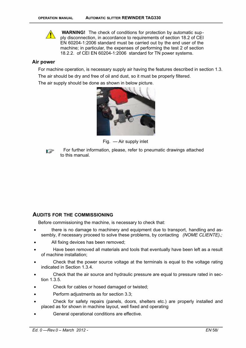
OPERATION MANUAL AUTOMATIC SLITTER REWINDER TAG330
WARNING! The check of conditions for protection by automatic sup-ply disconnection, in accordance to requirements of section 18.2 of CEIEN 60204-1:2006 standard must be carried out by the end user of themachine; in particular, the expenses of performing the test 2 of section18.2.2. of CEI EN 60204-1:2006 standard for TN power systems.
Air power
For machine operation, is necessary supply air having the features described in section 1.3.
The air should be dry and free of oil and dust, so it must be properly filtered.
The air supply should be done as shown in below picture.
Fig. — Air supply inlet
For further information, please, refer to pneumatic drawings attachedto this manual.
AUDITS FOR THE COMMISSIONING
Before commissioning the machine, is necessary to check that:
there is no damage to machinery and equipment due to transport, handling and as-sembly, if necessary proceed to solve these problems, by contacting (NOME CLIENTE).;
All fixing devices has been removed;
Have been removed all materials and tools that eventually have been left as a resultof machine installation;
Check that the power source voltage at the terminals is equal to the voltage ratingindicated in Section 1.3.4.
Check that the air source and hydraulic pressure are equal to pressure rated in sec-tion 1.3.5.
Check for cables or hosed damaged or twisted;
Perform adjustments as for section 3.3;
Check for safety repairs (panels, doors, shelters etc.) are properly installed andplaced as for shown in machine layout, well fixed and operating
General operational conditions are effective.
Ed. 0 —Rev.0 – March 2012 - EN 58/74

OPERATION MANUAL AUTOMATIC SLITTER REWINDER TAG330
WARNING! The machine cannot be operated before the testing hasbeen performed successfully by PPM Industries SpA.
Ed. 0 —Rev.0 – March 2012 - EN 59/74

OPERATION MANUAL AUTOMATIC SLITTER REWINDER TAG330
MAINTENANCEThe machine was designed and constructed so as to reduce as much as possible the ne-
cessary maintenance and to ensure proper operation over the years without troubles.
It is however important to note that maintenance should not be seen only as a periodiccheck of the machine operation, but with the analysis and consequent remedy of all thosecauses which, for any reason, put it out of service. In fact, many machine and control devicefailures can be avoided by implementing an appropriate program of preventive maintenance.
After any maintenance work, the machine shall be tested to verify proper operation.
Before performing maintenance operations, please, carefully follow the instructions de-scribed in section 1.5.1.
WARNING! It is appropriate that all maintenance performed on themachine is recorded on a chart showing: Intervention date, interven-tion type and the maintenance personnel who performed.
OILS AND GREASES USED IN MAINTENANCE According to the use, should be used lubricants of the categories listed in the following
table and those contained in next pages:
LUBRICANT TYPE USED CLASS
LUBRICANT OIL XM2
WARNING! During the use and handling of oils, please, follow the in -structions of their relevant safety data sheet.
WARNING! It is recommended not to disperse grease and oil into theenvironment and to comply with le local regulations for disposal of ex-haust lubricants.
In the following pages are shown the comparative tables of equivalent oils and greases.
Ed. 0 —Rev.0 – March 2012 - EN 60/74

OPERATION MANUAL AUTOMATIC SLITTER REWINDER TAG330
Ed. 0 —Rev.0 – March 2012 - EN 61/74

OPERATION MANUAL AUTOMATIC SLITTER REWINDER TAG330
Ed. 0 —Rev.0 – March 2012 - EN 62/74

OPERATION MANUAL AUTOMATIC SLITTER REWINDER TAG330
Ed. 0 —Rev.0 – March 2012 - EN 63/74
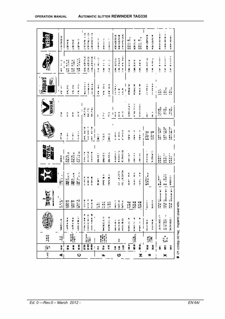
OPERATION MANUAL AUTOMATIC SLITTER REWINDER TAG330
Ed. 0 —Rev.0 – March 2012 - EN 64/74

OPERATION MANUAL AUTOMATIC SLITTER REWINDER TAG330
PREVENTIVE MAINTENANCE ON THE MACHINE
General Checks
Check monthly the tightness of screws, nuts, flanges and fittings of all parts on the ma-chine. Proceed to their clamping in case they result loosened.
WARNING! In case of maintenance on the machine, you must use thesafety devices fitted on the machine and personal protective equip-ment provided.
Machine cleaning
We recommend at least every 8 hours of operation, to clean the visible parts of the ma-chine and to free from dust by using compressed air or an appropriate vacuum cleaner.
WARNING! If during the cleaning operations of the machine are cre-ated inhalable powders provide the operators with adequate facemask and ventilate properly the environment.
WARNING! Operators must follow the proper handling instructionscontained in the safety data sheets of chemicals from time totime used for cleaning the machine and use suitable personal protect-ive equipment.
During clearing operations, pay attentions to machine general conditions, for timely inter-vention in case of failures and malfunction.
Regular maintenance and lubrication
Frequency Part Operation to perform
Two- monthly
All moving parts as from at-tached technical drawingsshowing the parts to lubricate /grease.
Grease the points shown in lubrication /greasing drawing using the provided devices(greasers/oilers).
QuarterlyChecking the status of thebelts.
Check the good condition of timing belts.
ELECTRIC SYSTEM
Proceed with regular monthly monitoring of the electrical connections inside the controlpanel and external electric wirings.
In particular, should be weekly checked:
The proper tightening of electric terminals of all devices and equipment;
The status of electrical contacts;
Machine limit switches status.
Ed. 0 —Rev.0 – March 2012 - EN 65/74

OPERATION MANUAL AUTOMATIC SLITTER REWINDER TAG330
SAFETY AND CONTROL / SIGNAL DEVICES EFFICIENCY CHECK Every day should be checked for good working of the machine's safety equipment, ensur-
ing that emergency systems come on line, the control and signalling devices are working prop-erly.
In particular the testing of safety devices must be done by involving each device individu-ally:
Pressing each emergency stop button;
Opening the interlocked guards.
WARNING! Operators should stop using the machine each time theysee an event of malfunctions in the control devices and must suddenlyreport them to their supervisors and maintenance service of (NOMECLIENTE).
WARNING! Do not use the machine for any reason, if it is foundthat any safety device is not working perfectly. . Immediately put themachine out of order docking in position of isolated circuits the powersupply circuit breakers. Restart the machine only when all the safetydevices are again in perfect efficiency.
WARNING! Please, contact (NOME CLIENTE)supervision and main-tenance if you need to perform operations on the safety and controldevices; (NOME CLIENTE) disclaims any liability for damages or injur-ies resulting from operations on a safety device or control system car-ried out by unauthorized personnel from PPM Industries SpA.
WARNING! (NOME CLIENTE)disclaims any liability for damage or in-jury resulting from alteration or tampering with safety devices or controlof the machine.
EXTRAORDINARY MAINTENANCE Any extraordinary maintenance must be carried out by the technical service of PPM Indus-
tries SpA or its authorized personnel. Information for personnel to be contacted for any assist-ance can be obtained directly from PPM Industries SpA. For a correct and quick resolution ofthe problem, you must notify PPM Industries SpA the codes identifying the machine and the de-scription of the fault, or what are the visible symptoms, and under what conditions it occurs.
WARNING! Any form of warranty is void if on the machine are per-former interventions carried out by unauthorized personnel from PPMIndustries SpA.
SPARE PARTS All spare parts must be obtained from PPM Industries SpA, which will provide them directly
or give you information on where they can be found.
Ed. 0 —Rev.0 – March 2012 - EN 66/74

OPERATION MANUAL AUTOMATIC SLITTER REWINDER TAG330
Please note that any extraordinary maintenance must be performed by personnel of /or authorized by PPM Industries SpA.
WARNING! Any form of guarantee lapses if are used replacementparts other than those originally installed on the machine.
Ed. 0 —Rev.0 – March 2012 - EN 67/74

OPERATION MANUAL AUTOMATIC SLITTER REWINDER TAG330
SETTINGSPerforming settings on the machine follow the instructions described in section 1.5.1.
JUMBO ROLL LOADING – UNWINDING AREA
In the following image is shown the area of the machine concerned with the positioningoperation of the jumbo roll.
Fig. 54 – Jumbo roll unwinding area
Fig. 55 – Jumbo roll area control panel
Referring to Figure 55 for the location of the controls, the procedure to be followed is:
1. Position the selector “BLOCK COIL” to “OFF”.
Ed. 0 —Rev.0 – March 2012 - EN 68/74

OPERATION MANUAL AUTOMATIC SLITTER REWINDER TAG330
2. Move to rest position the roll pressure cylinder by the selector “HOLDER COIL”
3. Place in position the jumbo roll to be used.
4. Block the jumbo roll carrying crankshaft by the selector “BLOCK COIL” positioned to “ON”.
5. Use the pulse button to reroute the film in the machine, following the foreseendrawing.
REMARK In case of loading a jumbo roll having the film alreadyrouted by a previous jumbo roll, is sufficient adhere the first strip of thefilm with the end of the film left in the machine of the previous jumboroll, and routing the new film up to the work start position.
On the jumbo roll holder device is assembled a device that allows to detect the eventual un-wound film breaking. When this happens, a signal is send to main control panel to stop the ma-chine at once.
Jumbo roll breaking control device
At the appropriate time, insert the cutting device to use.
The machine uses two types of cutting: By blades and by saw blades with pressure.
The cutting blades can be positioned by a hand wheel control above or below the materialto be cut.
Cutting blades positioning hand wheel
The blade cutting device requires the displacement of the blade holder bar:
● In the cutting position (blades engaged);
● With the disengaged blades for an eventual blade holder bar change.
Fig. 56 – Cutting type selectors
For the cutting pressure with circular blades, there is provided a two position se-lector "PRESSURE BLADE" positioned on the control panel that:
Ed. 0 —Rev.0 – March 2012 - EN 69/74

OPERATION MANUAL AUTOMATIC SLITTER REWINDER TAG330
● On the "ON" position approaches the bar blade holder to the hardened cylinder tomake the cut;
● In the “OFF” position removes the blade holder bar from the hardened cylinder.
When you place the blade holder bar on the hardened cylinder, you must also activatethe switch on the control panel "CUTTING PRESSURE", positioning it to "ON" to provide thenecessary and proper pressure to the blade holder bar on the hardened cylinder.
REMARK: In both cases, prior to operating the slitter-rewinder machine, it is always neces-sary first to engage the cutting blades or pressurizing the blade holder bar in the case of useof cutting pressure.
The blades / circular blades have the pitch of the width of the tape to be cut.
The tape divided into strips of predetermined width is rerouted up to the rewinding posi-tion on cardboard cores.
WARNING! The jumbo roll positioning on the unwinding device mustbe carried out being outside the protected area.
WARNING! With the machine running, it is forbidden to enter the un-winding area. You can access unwinding area only to the followingconditions:
● Machine running at a slow speed; ● Controls on “manual” position.
CARDBOARD CORES LOADING
For the first preparation of loading with cardboard cores the machine already prepared forthe type of tape to rewind, you must follow the procedure described below.
Initial situation:a) Cardboard cores container empty;b) Cardboard cores upper and lower channel empty; c) Rewinding crankshafts on the slitter-rewinder without cardboard cores.
Cardboard cores container view
Ed. 0 —Rev.0 – March 2012 - EN 70/74

OPERATION MANUAL AUTOMATIC SLITTER REWINDER TAG330
Cardboard cores channels view
Rewound tapes discharger view (rear part)
Rewound tapes discharger view (front part)
Initial procedure:
Manually move the carriage with the shell in the loading position in front of the loading area;
Fig. 57 – Carriage shift
Ed. 0 —Rev.0 – March 2012 - EN 71/74

OPERATION MANUAL AUTOMATIC SLITTER REWINDER TAG330
1. Load the cardboard cores into the storing container and rotate the motor driving the disk holder crankshaft to enter the cores on the chute in the feeding channels. The cores will stop at upper retainer.
2. Move the carriage in cores loading position. 3. Lock the selector carriage block “STOP CYCLE POWER” on position “ON". 4. Push the button “STILL CLOSE SOULS” to lift the retainer and allow the cores to come
down in the ditch to its upper shell. REMARK: Prior to the release of the button, ensure that the upper channels are com-
pletely filled with cores.
5. Push the button “STILL OPEN SOULS” and a row of cores on upper chute are chan-nelled towards the lower zone. This operation must be repeated until in the upper andlower channels are 6 rows of cores.
6. At this point the shells are fed with cores. Push the button “RETURN PALLET” to re-move the pallet from the shells, making them close the lid. On the main control panel, the operator rotates the selector "STOP CYCLE POWER" to "OFF", reset the cycle with the button and drives the carriage for loading of cores on the crankshafts.
7. The system waits for cycle starting rewinding cycle signal. SAFETY DEVICE ON CARRIAGE MOVING
The automatic slitter – rewinder is equipped with a safety stop device that operates on car-riage moving. It can be controller manually by the provided button and automatically when thephotocell is activated. A provided light signals that the safety stop device is active.
With the safety stop device inserted (manual or automatic) in addition to stop the running ofthe carriage loading and unloading the cores is prevented also the movement of the cuttingdevice and the final shafts rotation. In practice, to carry out the displacement manoeuvres, thefinal cutting and the shaft rotation, it is always necessary in advance to eliminate the presenceof the stop by pressing the button.
SAFETY DEVICE FOR CORES PRESENCE
On the shell that puts the cores on the shanks, is mounted a device that monitors the pres-ence of the cores in their grooves. When the core is properly positioned in its groove, the clos-ing of the lid disengages the sensing device.
If one or more cores are missing in the shell, the device remains active and feedsa delayed timer which will give the signal to stop the carriage.
In this case, with the proper button is necessary to open again the shell lid and manuallyfeed the missing core or cores.
Close again the lid, reset the system and push the proper button to start the feeding opera-tion.
SAFETY BRAKING DEVICE ON CARRIAGE MOVING
Onto the translation cylinder for tapes loading / unloading is mounted and hydraulic brakingdevice at stroke end. This device brakes the cylinder in its final part of translation stroke.
MEASURE EXCHANGE 1. Unload the crankshafts with the rewound tapes and while the carriage unloads, turn the
cycle stop selector to position “I”.
Ed. 0 —Rev.0 – March 2012 - EN 72/74

OPERATION MANUAL AUTOMATIC SLITTER REWINDER TAG330
Cylinders with rewound tapes view
2. Move the core bench by the selector with removable key in centre position (RIGHT-LEFT).
3. Remove the two shells (upper and lower)
4. Remove the upper / lower loading / unloading racks.
5. Assembly all the parts having the new measure and load the cores onto the extrac-ted crankshafts;
6. Perform manual rotation of the shafts by manually pressing the limit switch and act-ing simultaneously on the extraction button to release the two shafts of previous meas-ure and replace them;
7. Click manually the return button to return the changed crankshaft of the new measure.
8. Rotate the crankshaft and change the other two.
9. Change the blade holder bar with the one of the new measure.
CAUTION: Always protect the blades with the proper sleeve to prevent injury!
At point “2” when you exchange shell, always check that the lid that holds thecores is adjusted so that when the lid is closed, the cores have only a small stake in theirhome.
Also check that the seats of the shell where the cores are staying are alignedwith the feeding channels of the feeding system.
You should also replace the complete core container, using a lifting device suit-able for the weight to handle.
REWOUND TAPER DISCHARGER
When changing measure, please, change also the two reeds (view image).
Reeds to be changed
Ed. 0 —Rev.0 – March 2012 - EN 73/74

OPERATION MANUAL AUTOMATIC SLITTER REWINDER TAG330
DECOMMISSIONING If the machine becomes inactive, is recommended to remove it from the service or to affix
onto the machine a clearly visible a warning note.
The machine is built with metal and plastic components: So the mostpart of the material is effectively recyclable.
At the decommissioning of the machine is advisable to perform a separation of the variousmaterials for later reuse or disposal.
All materials used to build the machine are not toxic or dangerous to the health of workers,so they can be handled without special precautions.
WARNING! The lubricant fluids must be properly disposed (accordingto applicable laws and regulations) and not dissipated into environ-ment.
WARNING! The dismantling of the machine at the end of its usefullife should b e d o n e by personne l competen t and trained onthe proper manner of handling - and eventually of dismantling - of themachine. Use only facilities and lifting equipment suitable and in com-pliance with laws and regulations.
WARNING! Having to disassemble the machine to transfer to an-other site, please contact PPM Industries SpA.
Ed. 0 —Rev.0 – March 2012 - EN 74/74