Operating Methods for the Transport of Loaded & Empty RSC ...
35
1 Operating Methods for the Transport of Loaded & Empty RSC / York Containers in Royal Mail Vehicles This supersedes all previous loading instructions and is a mandatory requirement. Prepared by: Royal Mail Network Richard Low P/L 5700 7295 Version 2 29/11/2005 Additional sections added August 2015 and October 2017
Transcript of Operating Methods for the Transport of Loaded & Empty RSC ...

1
Operating Methods for the Transport of Loaded & Empty RSC / York
Containers in Royal Mail Vehicles
This supersedes all previous loading instructions
and is a mandatory requirement.
Prepared by: Royal Mail Network
Richard Low P/L 5700 7295
Version 2
29/11/2005 Additional sections added August 2015 and October 2017

2
Contents
Page 3
Introduction
Page 4 Section 1 Operating Principles - Curtain Sided Vehicles
Page 5 Section 2 Operating Principles - Side loading of Curtain Sided Vehicles
Page 7 Section 3 Operating Principles - Box Vehicles
Page 8 Section 4 Load security diagrams RSCs & Yorks
Page 12 Section 5 Loading Methods - Yorks - Using a Dock Leveller - Fore & Aft method
Page 13 Section 5a Loading Methods - Yorks - Using a tail lift-Block of 13 Method
Page 14 Section 6 Loading Methods - Yorks - using a tail lift
Page 15 Section 7 Loading Methods - Yorks - Latest Strapping Type
Page 16 Section 8 Load Security diagrams
Page 20 Section 9 Loading Methods - Mixed Loads
Page 20 Section 10 Mixed loads security diagrams
Page 22 Section 11 Moving empty Yorks
Page 23 Section 11.1 Loading 550cf~740cf vehicles using a Dock Leveller
Page 24 Section 11.2 Loading 550cf~740cf vehicles using a tail lift
Page 24 Section 11.3 Unloading 550cf~740cf vehicles using Dock Leveller
Page 25 Section 11.4 Unloading 550cf~740cf vehicles using a tail lift
Page 25 Section 11.5 Loading vehicles over 740cf using a dock leveller
Page 26 Section 11.6 Loading vehicles over 740cf using tail lift
Page 28 Section 11.7 Unloading vehicles over 740cf using a dock Leveller
Page 27 Section 11.8 Unloading vehicles over 1400cf using a tail lift
Page 27 Section 12 Nested Yorks security diagram
Page 28 Section 13 Vehicle Capacities
Pages 29-31 Section 14 Loading plan for Mini-Yorks (updated August 2015)
Page 32 Section 15 Mk 4 Parcel York Loading – Nested (updated Oct 2017)
Preface
This has been produced to ensure that a uniform method of load control is in existence throughout
the transport sections within the business.
This Policy should be the definitive reference, but must be considered when performing site specific
Risk Assessments/SSoW.
Additionally, on all new curtain sided vehicles we have revised the strapping positions for York
containers, whereby an additional cleat has been fitted and some extra eyes in the webbing. This
has proved to be more secure than the existing method, especially in stop/start conditions or where
there is a high frequency of sleeping policemen. It is available as a retro fit should the need arise.
Only staff instructed to operate dock levellers, tail lift and mechanical handling equipment should
do so.
Under no circumstances, Must any Mechanical Handling Equipment be driven over Bridging Plates or
Tail Lifts.

3
Introduction
Preventative safety measures: -
a) The task is to be carried out by a person with no known existing medical condition that
requireconsideration.
b) The task is not to be carried out by a young person (under 18), without supervision.
c) Due consideration to be given to any task likely to be carried out by an individual who
hasinformed their line manager they are pregnant.
d) Adequate competent supervision is available.
e) Adequate environmental conditions will be provided before any work starts.
f) Adequate Safe Access & Egress is available to the workplace/work area.
g) Plant & Equipment is suitable, sufficient and adequately maintained and subject to “before use
checks”.
h) That the tasks are carried out by a competent (trained or sufficiently experienced) or where
appropriate an authorised person.
i) The employee will utilise all control measures provided for their health & safety including any
appropriate PPE identified.
j) The employee will report any faults in the work equipment or shortcomings in the health & safety
systems to their line manager before commencing the task.
k) Employees will have had manual handling training.
l) Vehicles/trailers are parked correctly in a designated parking bay/area.
m) Employees should check that the ‘MHE Loading Label’ is fitted and that the trailer is suitable
forits intended use.

4
1. Operating Principles - Curtain sided vehicles
1. Reverse the vehicle onto the dock, open the shutter and deploy the dock leveller, if doors are fitted
it will be necessary to open these first before reversing onto the dock. If a tail lift is fitted it will
be necessary to lower the tail lift and reverse it below the dock leveller.
2. All vehicles must be fitted with load restraint straps. Which should be checked/replaced prior to
loading. In addition the posts and cleats should be inspected for serviceability. If in doubt contact
your line manager.
3. All straps should be fitted in the stowed position prior to loading from rear. (See figure 1). This
will avoid damage to the straps.
4. If side loading, open curtains and slide load-retaining posts/roof supports rearwards, if required.
Also ensure that the straps are not likely to create a hazard whilst loading/unloading commences.
5. Wherever possible heavy RSCs should be loaded as the lower container.
6. Under no circumstances must there be missing RSCs in any load situations, any shortages must be
met by filling the gaps with Empty RSCs, this is vital to ensure that the load cannot move. (See
figure 7)
7. Carefully drive in with the forklift or powered pallet truck and place the first RSC on the left or
right hand side up against the bulkhead.
8. Load each single or double stack of RSCs in the vehicle ensuring they are centrally located and
longitudinally positioned.
9. If required, Load second row of RSCs until a block of four is made (Max). i.e.:- 2 rows. (See
Figure 4)
10. Working from inside the body, release the first strap from its stowage point and ensure that
itpasses over the top corner of the rearmost RSC, then across the rear of the load and is secured to
an accessible floor or post hook receiver forward of the rear of the load. (See Figure 2, 3 & 6)
11. Release the second strap from its stowage point and position as above creating a cross over
ofstraps on the rear face of the containers. Repeat for every 2 rows. (Maximum of two rows
before strapping)
12. If only single RSCs are being collected, the diverting cleat must be used to lower the strap. This
islocated below the strap fixing point on every column and is rearward facing.
13. Do not mix single and double stacked RSCs within a group of 2 rows, double stacked
containersmust never be positioned rearward of single RSCs.
14. York containers may be carried in combination with RSCs but must always be rearward of a
blockof 4 RSCs. RSCs must not be loaded rearward of York containers (see figure 7).

5
2. Side loading for Curtain Sided vehicles
If there is a requirement to load/unload through the side of a trailer or rigid vehicle, perhaps at a customer
collection then the following process should be used:
1. Ensure that the vehicle is on firm level ground and that the park brake is fully applied.
2. Refer to the manufacturers information for correct method of curtain operation, however in most
cases:
• Release the buckles and release the tension in the curtain side.
• Disengage the curtain support pole, if loading an empty vehicle then the load should go in
by the bulkhead first.
• Slide the curtain evenly along the side of the vehicle, this will avoid bunching and
potential jamming of the curtain. Whilst opening the curtain check for open/loose gates
and the risk of falling items. Do not run when moving the curtain.
• There are many variants and you should refer to the manufacturers information for correct
method of support pole operation, however in most cases, you should lift up the locking
handle and slide the pole until it is clear and safely away from the area that you are
working. It maybe necessary to climb into the vehicle and ensure that the load restraint is
correctly stowed so that the pole is easily moved.
3. Ensure that the area is free from personnel whilst the FLT is working.
4. Access and Egress to the trailer must be via the steps provided. Refer to the Access and Egress
SSoW.
5. The load should be suitably secured when the first block of four single or eight double RSCs is
made. It will be necessary to refit the roof support poles before the straps can be correctly
positioned. Particular care should be made by the FLT operator to ensure sufficient clearance
above and below the RSCs whilst loading or unloading is being undertaken.
Only when the above points have been met should loading commence
Loading
1. The loading of all curtain sided trailers must commence from the front end of the trailer.
AllRSCs are to be loaded with the gates facing outwards. Do not load RSCs that are damaged or
with gates hanging off. Remember to always assess the load.
2. The Strapper assists the FLT operator in moving the sliding post forward on either side of
thetrailer to clear the double stack. FLT operator then loads the first two doubles. The Strapper
then assists the FLT operator to slide the removed posts back in place and lock them in position.
3. The FLT operator then loads the next two doubles. The Strapper then gains access to
thetrailer and passes the straps over the top of the RSCs and down to the FLT operator where the
Strapper secures the strap clip/hook onto the second pin on the trailer forward of the rear of the
RSCs (figure 6).

6
It is important that the buckle sits to the side of the RSC to prevent damage from the positioning
of the next cage. The Strapper tightens the strap whilst the FLT operator locks down the buckle.
4. Continue this process until you reach the last two doubles that need to be loaded. The
Strapperneeds to climb down from the trailer whilst until the last two doubles are being loaded
and then assist the FLT operator to slide the removed posts back in place and lock them in
position. The Strapper can then climb back onto the trailer to fit the last two straps.
5. Replace the curtain post and engage the tensioner lock, tension the front end of the
curtain.Engage stow handle and re-fit the safety catch. Fit and tension the curtain straps.
Unloading
1. Unloading to commence from the back end of the trailer. FLT operator and the Strapper
torelease the first two end straps. Strapper then gains access to the back of the trailer and
removes the straps from the first two RSCs and secures the straps to the end posts.
2. Strapper then steps down from the trailer and assists the FLT operator in moving the
slidingpost forward on either side of the trailer to clear the double stack.
3. FLT operator then removes the first two double stacks. Under No circumstances must
theStrapper re-enter the trailer until these two doubles have been removed.
4. Strapper then slides the removed posts back in place and locks them in position by means of
thecantilever-locking device. The Strapper then releases the next set of straps before climbing
back up on the trailer. The Strapper then removes the straps from over the RSCs and hands
them down to the FLT operator who will place them safely on the side of the sliding post until
the sliding posts are moved.
The Strapper should ensure that they are clear of the RSCs whilst the next two doubles are
removed.
5. Once the RSCs are removed, the Strapper can assist the FLT operator to move the next
twosliding posts from within the trailer. These should be secured next to the first two sliding
posts. Once the next two doubles have been removed the Strapper can assist the FLT operator
to slide the removed posts back in place and lock them in position.
6. The FLT operator then releases the next set of straps, to allow the Strapper to remove thestraps
from over the RSCs and hand them down to the FLT operator who will place them safely on
the side of the sliding post until the sliding posts are moved.
The Strapper should then ensure that they are clear of the RSCs whilst the next two doubles are
removed.
7. Repeat steps 5 & 6 to unload the rest of the trailer.

7
3. Box vehicles
1. Reverse vehicle onto dock, open the shutter and deploy the dock leveller, if doors are fitted it will
be necessary to open these first, before reversing onto the dock. Only trained personnel should
use a dock leveller. If a tail lift is fitted it will be necessary to lower the tail lift and reverse it
below the dock leveller.
2. Wherever possible heavy RSCs should be loaded as the lower container.
3. Under no circumstances must there be missing RSCs in any load situations, any shortages must be
met by filling the gaps with Empty RSCs, this is vital to ensure that the load cannot move. (See
figure 7)
4. Check that the vehicle/trailer has the ‘safe working MHE load label’ fitted. This must be
observed.
5. All vehicles must be fitted with load restraint straps. Which should be checked/replaced prior to
loading. If in doubt contact your line manager.
6. All straps should be stowed prior to loading. This will avoid MHE damaging the straps.
7. Ensure that the RSCs are positioned longitudinally, (as figure 4)
8. Secure using straps directly across the rear of the load, (See figure 5) after each two rows of RSCs
ensuring the straps are positioned with their ends forward of the rear of the load.
9. Do not mix single and double stacked RSCs within a row, double stacked containers must never
be positioned rearward of single RSCs. (See figure 7)
10. York containers may be carried in combination with RSCs but must always be rearward of RSCs.

8
4. Load security diagrams
Figure 2
Rear view of fitted straps used on a curtain side vehicle.
Figure 1 Straps in stowed position
Straps
9
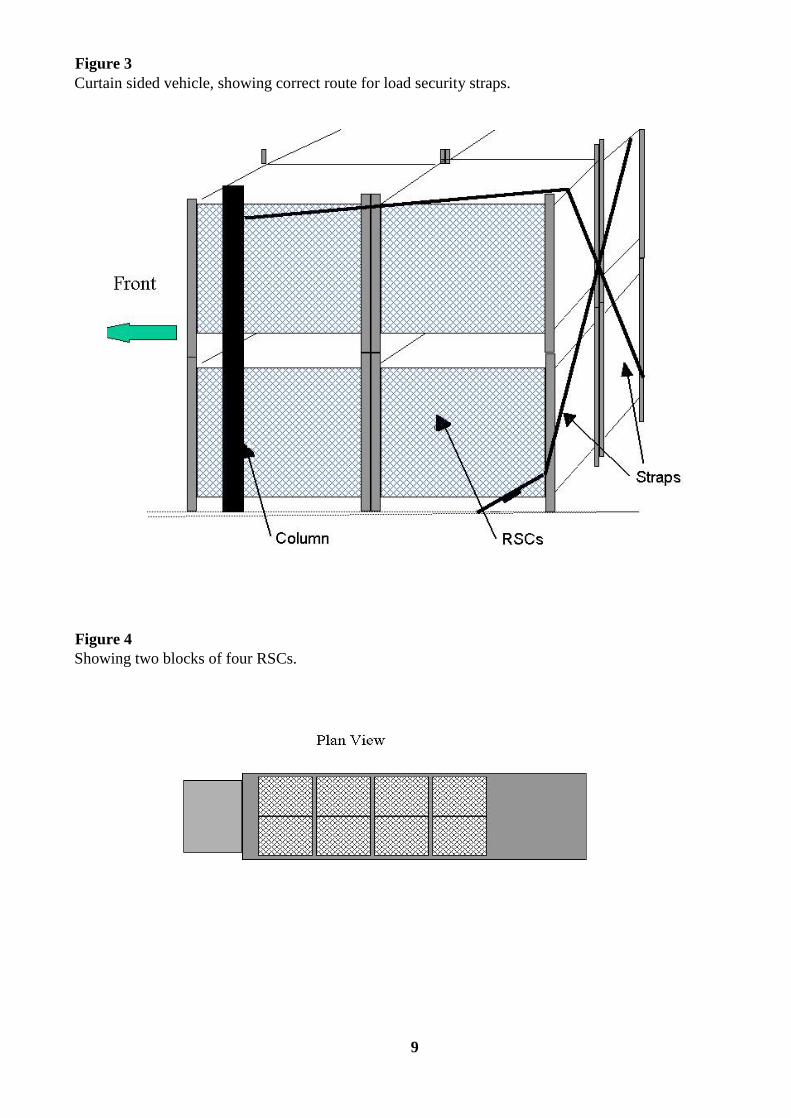
Figure 3
Curtain sided vehicle, showing correct route for load security straps.
Figure 4
Showing two blocks of four RSCs.

10
Figure 5
This shows the correct layout for Box Vehicles
This shows correct position of strap buckle
Straps

11
Figure 7
Under no circumstances must loads be transported like the examples below, this applies to both box
bodies and curtains.

12
5. Loading Methods – Yorks
Loading vehicles using a dock leveller - Fore & Aft method
1. Reverse vehicle on to dock and deploy the dock leveller. Only trained personnel should use a dock
leveller. If a tail lift is fitted it will be necessary to lower the tail lift and reverse it below the dock
leveller.
2. Check that vehicle is fitted with sufficient number of serviceable load restraint straps, also ensure
that the trailer is fitted with lowering cleats. Check that support posts are located in their correct
upper and lower positions and that the straps are in the parked position ready for loading. i.e.
Hooked on to front of the next rearward support post.
3. FIRST YORK - Using the yellow handle, push the loaded York over the dock leveller into the
vehicle and park it against the headboard. Position it centrally from vehicle sides (Fig 2). Ensure
the brake is applied.
4. SECOND & THIRD YORK- position it either side of the first York. This should leave a space of
approximately 200 mm between the sides of the curtains/box and the Yorks.
5. Repeat steps 3 & 4 for additional Yorks until three rows (9 Yorks) have been placed in the
vehicle. (See figure 3)
6. When York containers are not available in multiples of three i.e. 11 Yorks, secure as one block of
9 and one row of 2, if possible complete any shortfalls with empty Yorks.
7. Unhook the strap from its park position and route the strap around the strap-diverting cleat, (figure
5) ensuring that the strap remains in position and the buckle is in the ‘free’ mode. Locate the strap
round the rear of the Yorks, follow across to the opposite side and hook the strap onto either the
receiver at the bottom of the post or if more than one row is being secured, into a floor receiver
forward of the load. Tighten the strap and lock using the over centre buckle.
8. Repeat with opposite side load restraint strap.
9. Repeat steps 3 to 7 for additional Yorks.

13
5a. Loading Methods – Yorks
Loading trailers using a dock leveller – Block of 13 method
This enhanced load plan enables an extra 4 Yorks to be loaded compared to the conventional fore and aft
method allowing a total of 49.
1. Reverse vehicle onto the dock and deploy the dock leveller. Only trained personnel should use a
dock leveller. If a tail lift is fitted it will be necessary to lower the tail lift and reverse it below the
dock leveller.
2. Check that the vehicle is fitted with a sufficient number of serviceable load restraint straps. If
using a curtain side trailer ensure it is fitted with lowering cleats. Check that the support posts are
located in their correct upper and lower positions and that the straps are in the parked position
ready for loading. i.e. Hooked onto the front of the next rearward support post.
3. To ensure an even load spread, place the heavier Yorks along the centre of the trailer i.e. positions
3, 6, 9 & 12 etc.
4. FIRST YORK - Using the yellow handle, push the loaded York over the dock leveller into the
vehicle. Once at the headboard turn it to face the right hand wall of the trailer leaving 100mm
between the front of the York and the trailer sidewall. Ensure the brake is applied.
5. SECOND YORK- position it next to the first York at 90 degrees to the headboard leaving 100mm
between the front of the York and the side of the trailer.
6. THIRD & FOURTH - Wheel the next York to the front of the trailer parking it against the
headboard to the left of the other Yorks. Position the next York to the left of the previous one,
which should leave approx 100mm between the side of the York and the trailer side.
7. Load the remaining Yorks using the sequence in figure 3, which will give you a block of thirteen.
8. Unhook the strap from its park position and route the strap around the strap-diverting cleat, (figure
5 when using a curtain sided trailer) ensuring that the strap remains in position and the buckle is in
the ‘free’ mode. Locate the strap round the rear of the Yorks, follow across to the opposite side
and hook the strap into a floor receiver forward of the load. When loading a box trailer, hook the
strap into the opposite load track. Tighten the strap and lock using the over centre buckle
9. When using a curtain sided trailer, Repeat with the opposite side load restraint strap.
10. When York containers are not available in blocks of 13, if possible complete any short falls
withempty Yorks. Alternatively revert to the conventional fore and aft method.
Unloading trailer using a dock leveller – block of 13 method
The Yorks should be unloaded in the reverse order, using any available free space to rotate Yorks slightly
when necessary to release any bags that have become caught between the containers.
You must ensure that the load security straps, once released, are correctly stowed in their park position.

14
6. Loading vehicles and trailers using a tail lift
A vehicle tail lift must be used to load Yorks from ground level or from intermediate docks. Only trained
personnel are allowed to operate tail lifts. Always read the lift operating instructions.
1. Lower the open tail lift platform to the ground or intermediate dock, in line with tail lift
operations, ensure roll stops are in the pop up mode. Push loaded York on to tail lift. Allow York
rear wheels to rest against raised roll stop and apply the brake. Always load the offside York first.
Repeat for the second York if necessary. For RSCs load onto tail lift turn through 90 degrees and
then lower the HPT.
2. For Cantilever lifts, ensure the platform is level, raise the platform to vehicle floor level and
transfer York containers into the vehicle.
Once the York is inside the vehicle, procedure for loading is the same as steps 3 to 8 in section 5
and steps 3 to 9 in section 5a.
Unloading vehicles using a tail lift
The procedure to be used is the reverse of the above, however you should ensure that the load security
straps once released are correctly stowed in the park position using the hooks provided. (See Figure 4)
Ensure tail lift platform is level (Cantilever lifts) and roll stops are in the raised position before unloading
Yorks. Fixed wheels only (Not swivel wheels) to be rested against roll stop, apply the York brake before
lowering the platform.
Only release the brakes on York containers you intend to move.
For RSCs ensure that the roll stops are lowered and platform is flat, RSC to be lowered onto platform
before operation of the tail lift commences.

15
7. Yorks – Latest Strapping type
1. Reverse vehicle on to dock and deploy the dock leveller. Only trained personnel should use a dock
leveller. If a tail lift is fitted it will be necessary to lower the tail lift and reverse it below the dock
leveller. If loading the vehicle using a tail lift refer to the instructions in section 6.
2. Check that the vehicle is fitted with a sufficient number of serviceable load restraint straps. Check
that support posts are located in their correct upper and lower positions and that the straps are in
the parked position ready for loading, i.e. Hooked on to front of the next rearward support post.
3. Load the Yorks using either the procedure described in steps 3 to 6 in section 5 or steps 3 to
7insection 5a.
4. Unhook the strap from its park position and route the strap around the lower strap-diverting cleat
(figure 5), ensuring that the strap remains in position and the buckle is in the ‘free’ mode. Pull
the strap round to the approximate centre on the middle York, repeat for other side.
5. Hook the straps into the sewn in ring on the opposite webbing (both). Tighten the strap and lock
using the over centre buckle. One strap buckle will face inwards, this should be locked in the
approximate centre of the Yorks and all tightening should be carried out only on the strap that is
rear facing. (See following picture)
6. Not all vehicles will be equipped with sewn in webbing rings, it is acceptable to use hook to hook
for locating the straps.
Repeat steps 3 to 5 for additional Yorks. (See fig 2)
This example shows the correct location for the buckles and final position of the straps.

16
These show the webbing type retainers, please note however, it is acceptable to use the hooks directly
together on vehicles not equipped with the orange webbing loops.

17
8. Load Security Diagrams
Figure 1
Figure 2
Restraint Straps
Column
York’s
Diverting cleat

18
Figure 3
Plan V iew for Y ork’s
Figure 3a
Plan View for Yorks in Trailers
9
10
6
7
3
4
8 5 2 1
1 3
1 2 3
4 7
6
1 1 1 2
9
1 0
1 2
8 1 1
1 3

19
Figure 5
Diverting Cleat
Figure 4
Straps in stowed position

20
9. Loading Methods for mixed loads RSCs and Yorks
1. Reverse vehicle on to the dock and deploy the dock leveller. Only trained personnel should use a dock
leveller. If a tail lift is fitted it will be necessary to lower the tail lift and reverse it below the dock leveller.
2. Check that the vehicle is fitted with a sufficient number of serviceable load restraint straps. Checkthat
support posts are located in their correct upper and lower positions and that the straps are in the parked
position ready for loading ie hooked on to the front of the next rearward support post.
3. Load RSCs, please note that if double stacked, batches of 8 (two full rows) must be carried. Anypart loads
must be met by either filling with empties or breaking the load down to single level.
Note: No mixing of loads is possible with double stacked RSCs unless they meet above criteria.
Mixing of loads, RSCs and Yorks is possible as long as the RSCs are in a batch, then two rows of three Yorks can
be securely strapped.
Under no circumstances must any other combination be carried, RSCs must always be loaded first. (See figure 1)
RSCs only, Unhook the strap from it’s park position and ensure the buckle is in the ‘free’ mode, locate the strap
round the front of the RSC, follow across to the opposite side and hook the strap onto the receiver at the bottom of
the post forward of the load. Tighten the strap and lock using the over centre buckle. Use the same method for
opposite side. (See figure 2 of the RSC load securing diagrams).
Yorks only or RSC combination, Prior to loading. Unhook the strap from its park position and route the strap
around the strap-diverting cleat. Ensuring that the strap remains in position and the buckle is in the ‘free’ mode.
Locate the strap round the rear of the Yorks, follow across to the opposite side and hook the strap onto either the
receiver at the bottom of the post or if more than one row is being secured, into a floor receiver forward of the load.
Tighten the strap and lock using the over centre buckle. (See figure 2)
4. Repeat with opposite side load restraint strap.
5. Repeat steps 7 to 8 (Section 5 - Loading Methods) for additional Yorks.
Alternatively use the superseded strapping arrangement for Yorks (if fitted).
Loading vehicles and trailers using a tail lift
A vehicle tail lift must be used to load Yorks from ground level or from intermediate docks. Only load RSCs
individually on a tail lift. Under no circumstances must MHE be driven over a tail lift. A tail lift must never be
used as a bridging plate for MHE.
Step 1 Lower the open tail lift platform to the ground or intermediate dock, in line with tail lift operations,
ensure roll stops are in the pop up mode. Push the loaded York onto the tail lift. Allow York rear
wheels to rest against raised roll stop and apply the brake. Always load the offside York first.
Repeat for the second York if necessary. For RSCs load onto tail lift turn through 90 degrees and
then lower the HPT.
Step 2 For Cantilever lifts, ensure the platform is level. Raise the platform to vehicle floor level and
transfer York container/RSC into the vehicle.

21
Once the York/RSC is inside the vehicle, procedure for loading is the same as steps 2 to 8 in
section 3 for a box vehicle and steps 3 to 6 in section 5 for curtain sided vehicles.
Unloading Vehicles using a tail lift
The procedure to be used is the reverse of the above, however you should ensure that the load security straps once
released are correctly stowed in the park position. (See figure 4, Section 8)
Ensure tail lift platform is level (Cantilever Lifts) and roll stops are in the raised position before unloading Yorks.
Fixed wheels only (Not swivel wheels) to be rested against roll stop, apply the York brake before lowering the
platform.
Only release the brakes on the York containers that you intend to move.
For RSCs ensure that the roll stops are lowered and the platform is flat. RSC to be lowered onto the platform
before operation of the tail lift commences.
10. Load Security diagrams for mixed loads
Figure 1

22
11. Moving Empty Yorks
The operating methods apply to vehicles designed to carry York containers, which can be loaded/unloaded from a
dock leveller, or tail lift.
Operating Principles
1. All vehicles must be fitted with load restraint straps.
2. The preferred method of moving empty York containers is in the single assembled state. If tail lifts are
used this is the only acceptable method. It is acknowledged that significant time advantages can be gained
from moving multiple nested Yorks. However, this method should only be considered where dock
levellers are available and where ground conditions are good.
3. A local risk assessment must be carried out to ensure that the method selected for moving empty Yorks is
acceptable.
4. A York container should always be moved in the assembled state when loading to or unloading from a
vehicle using a tail-lift.
5. The principles for handling York containers described in the "Handling the Future"
Containerisation manual must be observed. The only variation in this Safe Systems Of Work relates to the
nesting arrangement in road vehicles, and the movement of nested Yorks in the specific circumstances
described in this document.
6. It is only necessary to nest York containers in road vehicles when the quantity exceeds vehicle capacity for
assembled York containers.
IMPORTANT Risk assessment has demonstrated that loading nested Yorks on vehicle tail lifts involves
intolerable risks and must not be used under any circumstances.

23
Operating Methods
11.1 Loading 550cf ~ 740cf vehicles using dock leveller
Figure 1 (P27) shows the loading pattern for these vehicles.
STEP 1 Reverse vehicle on to dock and position dock leveller. If a tail lift is fitted, it will be necessary to lower
the tail lift and reverse it below the leveller.
STEP 2 Check that vehicle is fitted with sufficient number of serviceable load restraint straps. (See table l, P28)
STEP 3 FIRST YORK - Using the yellow handle push the assembled York over the dock leveller into the
vehicle and park it against the head board in an assembled state. Position it approximately 200mm (8
inches) from vehicle side (Fig 1). Ensure the brake is applied.
STEP 4 SECOND YORK - Repeat Step 3 for second York but position it on the other side of the vehicle. This
should leave a space of approximately 400 mm between the two Yorks.
STEP 5 Wheel next assembled York into the vehicle until approximately one metre from the parked Yorks.
Walk to front (open end) of the York, lift and lock the base in upright position.
STEP 6 Walk back to the braked end of the York, release brake, splay open the sides of the York and nest the
York over the assembled York and apply the York brake.
STEP 7 Repeat steps 5 to 6 except that the York is nested in a second row ensuring that it overlaps the nested
York in row 1. Successive Yorks should be positioned approximately one metre behind the previously
nested York before being collapsed and nested alternatively in row 1 and then in row 2, maintaining
the overlapping of York sides between the Rows.
STEP 8 Repeat above process until all Yorks are loaded. Ensure that a minimum space of 500 mm is left at
the rear of the vehicle to provide a working space when unloading Yorks using a tail lift.
STEP 9 Secure the load using a load restrain strap.
Notes
1. It is essential that the Yorks are nested alternatively on the left and right, building up both rows
evenly. This will make nesting and un-nesting of Yorks much easier.
2. Each nested York must be braked in turn to avoid movement on gradients.
IMPORTANT Under no circumstances should the vehicle be loaded with only a
single row of nested Yorks.

24
11.2 Loading 550 cf~740cf vehicles using a tail lift
Where a dock leveller is not available, a vehicle tail lift must be used to load Yorks from ground level or from
intermediate docks.
STEP 1 Lower tail lift to ground or intermediate dock and push assembled York on to Tail lift
by following the process for loaded Yorks.
STEP 2 Raise tail lift to vehicle floor and transfer York container into the vehicle.
STEP 3 FIRST YORK – Using the yellow handle push the York against the headboard in assembled state,
approximately 200mm (8 inches) from vehicle side (fig 1).
Ensure that brake is applied.
Once the York is inside the vehicle, the procedure for loading is the same as steps 4 to 8 in section 11.1.
11.3 Unloading 550cf ~ 740cf vehicles using dock leveller
IMPORTANT Yorks must be unloaded in a correct sequence
otherwise it will be difficult to un-nest the Yorks.
STEP 1 Reverse vehicle on to dock and position dock leveller. If a tail lift is fitted, it will
be necessary to lower the tail lift and reverse it below the leveller.
STEP 2 Release load-restraint strap and store safely.
STEP 3 Identify the York in one row that overlaps a York in the second row (in fig 1 this is
a York in row 2). This is the first York to be unloaded. Release brake on this York. Grasp
the two-hinged sides of the Yorks and splay the York side open and pull it backwards, clear
of the nested Yorks.
STEP 4 Apply brake, walk around to front open end of the York, and assemble the York.
STEP 5 Walk around to the braked end of the York, release brake and manoeuvre York
around and push it to park area.
STEP 6 Repeat above steps ensuring that Yorks are unloaded from alternate rows in a
correct sequence.
Note During transit, compacting may occur and a certain amount of manoeuvring may be
necessary to untangle the castor mounting.

25
11.4 Unloading 550cf-740cf vehicles using a tail lift
The procedure for unloading vehicles is similar to section 11.3 except that the Yorks have to be lowered to the
ground or intermediate dock using a tail lift.
When unloading Yorks using a tail lift, each York must be assembled before being loaded onto a tail lift.
11.5 Loading vehicles over 740cf using a dock leveller
Figure 2 shows a loading pattern for 1400cf and larger vehicles.
Table 1 shows the number of straps which must be used for each vehicle type, when loaded to its maximum
capacity.
For each vehicle size loaded to capacity, block sizes are suggested in Table 1.
Two methods for loading vehicles may be used.
Method A
Where empty Yorks to be loaded to a vehicle are stored in an assembled form, the loading procedure is
similar to the procedure in section 11.1 except that the strict nesting sequence is not necessary due to the
wider body of the vehicle. Both rows should still be built up progressively to ensure that there will always
be a straight face of Yorks across the two rows, which will allow for effective securing of the load.
Method B
Where the empty Yorks are already stored in a nested form, the Yorks may be moved and loaded in a nested
form as described in this section.
CAUTION This method of moving empty Yorks involves increased risk due to:
• reduced control
• exposed knuckles
• less than optimum manoeuvrability.
Local managers are required to carry out a local risk assessment to ensure that conditions are suitable for moving
nested Yorks. Staff must be informed of any risks.

26
OPERATING METHOD
STEP 1 Load the first two Yorks in an assembled state as per steps 3 & 4 in section 11.1.
STEP 2 Walk to a row of nested Yorks and pull two or three nested Yorks clear from the rest of
nested Yorks.
STEP 3 Walk to the brake end of the Yorks and then grab the top of nested side frames of the Yorks.
STEP 4 Exercising caution, manoeuvre and push the nested Yorks over the dock leveller and push the nested
Yorks over the first assembled York in the vehicle.
STEP 5 Apply the York brake to the last York.
STEP 6 Repeat step 4 above , except, nest Yorks over the second assembled York.
STEP 7 Repeat above process, nesting Yorks in the alternate rows.
Note A load restraint strap must be used to secure each "block" of nested
Yorks - maximum of 40 Yorks per block (2 rows of 19).
11.6 Loading vehicles over 740cf using tail lift
The loading procedure is similar to the procedure in section 11.2 except that the strict nesting sequence is
not necessary due to the wider body of the vehicle. Both rows should still be built up progressively to
ensure that there will always be a straight face of Yorks across the two rows. This will allow for effective
securing of the load.
11.7 Unloading vehicles over 740cf using a dock leveller
Two methods for unloading vehicles may be used
Method A
If the Yorks to be unloaded are required to be stored in an assembled state, the procedure for unloading is
similar to the procedure outlined in section 11.3 except that the Yorks may be unloaded from either row and
a strict sequence does not have to be followed, although desirable.
Method B
If the Yorks to be unloaded are to be stored nested then the following procedure should be used.
CAUTION This method of moving empty Yorks involves increased risk due to:

27
• reduced control
• exposed knuckles
• less than optimum manoeuvrability.
Local managers are required to carry out a local risk assessment to ensure that conditions are suitable for
moving nested Yorks. Staff must be informed of any risks.
OPERATING METHOD
STEP 1 Release load restraint strap and store it, clear off the floor.
STEP 2 Release the York brake and pull two or three nested Yorks clear from the row of nested Yorks.
STEP 3 Walk to the open end of the nested Yorks, grab the top of nested side frames of the Yorks.
STEP 4 Exercising caution, manoeuvre and push the nested Yorks from the open end, over the dock leveller and
push the nested Yorks to storage location and nest them over existing row of nested Yorks or start a new
row.
STEP 5 Repeat steps 2 to 4 until unloading is completed.
11.8 Unloading Vehicles over 1400cf using a tail lift
The procedure used here is the same as the procedure in section 11.4 except that the unloading sequence is not
critical.

28
12. Nested Yorks Load security
13. Vehicle Capacities
Table 1 shows expected capacities for vehicle types using the loading pattern as per fig 1 & 2, and the number of
vehicle load restraint straps which must be used to secure the load. The notes below correspond to each vehicle
type and specifies the number of Yorks to be restrained by each strap.
TABLE 1
Vehicle Width
mm
Length
mm
Height
mm
Load
Pattern Note 1
Total no
of Yorks Note 2
Total no
of Load
Restraint
Straps
Remarks
550 cf 6 Tonne IVECO Ford 2080 3330 1000 Fig 1 24 1 Note 3
600 cf GRP Box Body 2100 4100 1000 Fig 1 34 1 Note 4
740 cf GRP Box Body 2085 4870 1065 Fig 1 48 1 Note 5
1400 cf 17t GRP Leyland 2365 7260 1320 Fig 2 72 2 Note 6
9.1m GRP Box TIDD Semi Trailer 2380 9130 1300 Fig 2 90 3 Note 7
12.2m GRP Box TIDD Semi Trailer 2360 12120 1270 Fig 2 120 4 Note 8

29
13.4m GRP Box Semi trailer 2370 13260 1250 Fig 2 136 4 Note 9
13.6m GRP Box Semi trailer 2440 13300 2580 Fig 2 136 4 Note 9
Notes
1. Load pattern Figure 1 has two rows of nested Yorks loaded in specified sequence.
2. This allows 500 mm working space at rear of vehicle.
3. One assembled + 11 nested per row X 2 rows
4. One assembled + 16 nested per row X 2 rows
5. One assembled + 23 nested per row X 2 rows
6. Two blocks - each block of 36 Yorks (18 nested Yorks X 2 rows)
7. Three blocks - each block of 30 Yorks (15 nested Yorks X 2 rows)
8. Four blocks - each block of 30 Yorks (15 nested Yorks X 2 rows)
9. Four blocks - each block of 34 Yorks (17 nested Yorks X 2 rows)
All vehicle capacities allow for approximately 500 mm of operating space at the rear of the vehicle.
14. Load Plan Mini-Yorks
Approved Load plans (reference SAC1 Transportation and restraint of mini York’s v.2.2)
15. Load Plan Mk 4 Parcel Yorks
Approved Load plans (reference York Container Mk4 SAC1 & WECSA)

30

31

32

33

34
Vehicle
Size
Bottom
Deck
Top
Deck
Swan
Neck
York Nested
Configuration
( ] = Strap)
Visual
Vehicle Configuration
Total Mk4
LoadedComments
7.5t 30 N/A N/A9]6
9]630
Do not tightly compact nested
Yorks
17t 72 N/A N/A18]18
18]1872 Standard Nesting
Box 144 N/A N/A18]18]18]18
18]18]18]18144 Standard Nesting
75DD 90 30 48
TD 15]15
TD 15]15
BD 18]12]9]6
BD 18]12]9]6
168No Nesting on Top Deck
Fixed Straps on Bottom Deck
95 DD 156 138 N/A
TD 18]18]18]15
TD 18]18]18]15
BD 18]18]21]21
BD 18]18]21]21
294Top Deck Door in Place
Fixed Straps on Bottom Deck
dictate layout
98 DD 144 168 N/A
TD 18]18]18]18
TD 18]18]18]18
BD 18]21]21]24
BD 18]21]21]24
312Fixed Straps on Bottom Deck
dictate layout
110 DD 174 174 N/A
TD 18]18]15]15]21
TD 18]18]15]15]21
BD 18]18]24]18]9
BD 18]18]24]18]9
348
Pillar on TD dictate strapping
postion Fixed Straps on
Bottom Deck dictate layout
Mk4 Parcel York Vehicle Loading - NESTED
Where loaded with other York types, revert to the standard loading plan.

35