
OPERATING INSTRUCTIONS Two-speed Gearbox · OPERATING INSTRUCTIONS . Two-speed Gearbox . 023636....
34
OPERATING INSTRUCTIONS Two-speed Gearbox 023636 019928 019927 Pulley Drive 2K2100 with STW 06.2009 Edition 4161 758 104a
Transcript of OPERATING INSTRUCTIONS Two-speed Gearbox · OPERATING INSTRUCTIONS . Two-speed Gearbox . 023636....
OPERATING INSTRUCTIONS
Two-speed Gearbox
023636
019928
019927
Pulley Drive 2K2100 with STW
06.2009 Edition
4161 758 104a

2K2100 with STW
2
Subject to alterations in design
Copyright by ZF
Reproduction, in whole or in part, is only allowed with our written approval and authorization.
Printed in Germany
06.2009 Edition
4161 758 104a

Operating Instructions
2K2100 with STW Contents
3
1 Preface.....................................................................................................................................................5
1.1 Safety instructions .........................................................................................................................5 1.2 ZF instructions ...............................................................................................................................5 1.3 Service products.............................................................................................................................6
2 Application and design ..........................................................................................................................7
2.1 Application ....................................................................................................................................7 2.2 Features..........................................................................................................................................7 2.3 Design ............................................................................................................................................8 2.4 Technical data ................................................................................................................................9 2.5 Installation positions, 2K2100 .....................................................................................................10 2.5.1 Installation positions, 2K2100 with STW (spur gear stage) ........................................................11
3 Initial installation .................................................................................................................................12
3.1 Axial runout, radial runout and length tolerances – drive motor .................................................12 3.2 Balancing .....................................................................................................................................13 3.2.1 Semi-key balancing......................................................................................................................13 3.2.2 Full-key balancing .......................................................................................................................13 3.3 Mounting of 2K2100 without STW (spur gear stage) on motor/gearbox....................................14 3.4 Adaptation, motor/gearbox ..........................................................................................................15 3.4.1 Open design .................................................................................................................................15 3.4.2 Closed design, on request (with shaft seal)..................................................................................16 3.4.3 Open design with adapter ring for 2K2100, on request ...............................................................17 3.5 Mounting the gearbox..................................................................................................................18 3.6 Output as STW (spur gear stage) gearbox ...................................................................................19 3.6.1 Option: version with belt drive ....................................................................................................20 3.6.2 Option: version with coaxial output, only on request ..................................................................21 3.7 Electrical connection, gearchange ...............................................................................................21 3.7.1 Shift unit ......................................................................................................................................21 3.7.2 Checking, adjusting and exchanging the shift unit on the 2K2100 gearbox................................22 3.7.3 The cover (item 082) is removed from the shift unit for checking all functions .........................23 3.7.4 Checking the slip clutch for the correct friction torque ...............................................................23 3.7.5 Checking the limit switches.........................................................................................................23 3.7.6 Shift logic for 1st and 2nd gear....................................................................................................24 3.7.7 Shift logic for centre position ......................................................................................................25 3.8 Lubrication...................................................................................................................................26 3.8.1 Recirculating lubrication..............................................................................................................26 3.8.2 Ports and connections for lubrication ..........................................................................................27

Operating Instructions
Contents 2K2100 with STW
4
4 Taking into operation...........................................................................................................................29
4.1 Initial inspection...........................................................................................................................29
5 Maintenance..........................................................................................................................................29
5.1 Oil change ....................................................................................................................................29
6 Repair ....................................................................................................................................................30
6.1 Gearbox fault checklist ................................................................................................................30 6.2 Gearbox removal..........................................................................................................................31 6.3 Hub...............................................................................................................................................31
7 Frequently Asked Questions (FAQs) ..................................................................................................32
Operating Instructions
2K2100 with STW Preface
1 Preface 1.1 Safety instructions
• All persons repairing ZF units are responsible for their own work safety.
This documentation is intended for specialists who have experience to carry out maintenance and repair work. • Every applicable safety regulation and legal
requirement must be complied with in order to prevent injury to personnel and/or damage to the product during the course of maintenance and repair work.
The ZF product is documented in accordance with the design status as of the issue date.
The following safety notices are used in these operating instructions: • Repair staff should familiarize themselves with
these regulations before commencing work.
• Correct and proper repair of these ZF products can only be assured by appropriately trained specialists.
NOTE Used to highlight special sequences, methods, information, use of equipment etc.
• The organization in charge of repairs is responsible for ensuring that such training is given.
CAUTION Used when incorrect and improper operating procedures can cause damage to the product.
• Read these operating instructions carefully before commencing any testing or repair work. DANGER! !
Used when due lack of care and attention can cause injury to personnel or put lives at risk.
CAUTION Pictures, drawings and components do not always represent the original object but are used to illustrate working procedures.
The illustrations, diagrams and parts are not drawn to scale and no assumptions should be made regarding size and weight (including within a single illustration or drawing).
ENVIRONMENTAL HAZARDS! !Lubricants and cleaning products must not be poured onto the ground, into groundwater or down the drain.
Work must be performed as described in the text.
• Obtain and comply with the safety regulations relevant to these products issued by your local environmental authority.
Following the completion of any repair work and testing, the specialists must satisfy themselves that the product will function perfectly again.
• Collect used oil in a suitably large container. 1.2 ZF instructions
• Dispose of used oil, clogged filters, lubricants and cleaning products in accordance with local environmental protection regulations.
• Remove any traces of old seals or gaskets from mating faces. Use an oil stone to carefully remove any burrs or similar irregularities.
• Always follow the instructions issued by the manufacturer when handling lubricants and cleaning products.
• Carefully cover or shield open gearboxes to prevent the ingress of foreign matter.
5

Operating Instructions
Preface 2K2100 with STW
6
1.3 Service products
Product Name/specification Quantity (approx) [dm3]
Use Remarks
Grease
Shell Avania WR2
Fuchs Renolit CXEP2
Esso Beacon EP2
General-purpose
Gearbox oil
HLP 46 to ISO VG 46
Gearbox oil for recirculating lubrication
Can also be used for recirculating lubrication with heat exchanger
Gearbox oil
HLP 32 to ISO VG 32
Gearbox oil for recirculating lubrication with heat exchanger
Other gearbox oil specifications for lubrication on request.

Operating Instructions
2K2100 with STW Application and design
2 Application and design
7
2.1 Application
The ZF-DUOPLAN two-speed gearbox is mainly used in machine tool drives.
By way of example, the gearbox can be used in turning machines (horizontal B5, B5 ± 20° swiveled) or machining centers (vertical V1) thanks to its variable installation position. The gearbox is also suitable for use in many systems in which torque increase or speed reduction is required.
The gearboxes have coaxial output and are suitable for the high speeds generated in machine tool construction. Use with an STW (spur gear stage) gearbox gives rise to an axle offset, with the output spur gear being fixed to the machine spindle with clamping elements. In this case the machine spindle can be designed as a hollow shaft.
The 2K2100 variant with input flange ensures a short installation length thanks to the parallel arrangement of the gearbox and motor.
2.2 Features
• Two-speed gearboxes for AC and DC main spindle drives in machine tools
• Compact thanks to planetary design
• Directly flange-mountable to all AC, DC and standard motors
• Can also be used with pulley drive to save space in parallel configuration
• High running smoothness and low-noise operation thanks to helical gearing
• Low torsional backlash
• Easy to install
• High efficiency
• Motor gear change, with neutral position, idle
• Combined axial and radial force sensing as an option
2K2100 with input flange
019927
2K2100
019928
2K2100 with input flange and STW gearbox
023636

Operating Instructions
Application and design 2K2100 with STW
2.3 Design
The gearbox primarily comprises the following assemblies:
Connecting parts: • Drive hub with threaded pin (E) • Adapter plate with radial shaft seal and hub
bearings, as necessary, not shown here
8
Option: pulley drive: • Bearing housing (A) • Input bearings (B) • Input shaft (C) • Radial shaft seal (D) • Drive hub with threaded pin (E) • Grooved nut with retainer (F) • Fitted key (G)
Housing: • Gearbox housing (5)
Input/planetary drive: • Sun gear (6) • Ring gear (7) • Ring gear bearings (8) • Planetary gear carrier (K) • Axial bearings with cup springs (L)
Output, on request Option: shaft/flange: • Bearing housing (9) • Output bearings (10, 11) • Output shaft (12) (output flange) • Radial shaft seal (13)
Option: STW (spur gear stage) Housing (P) Input spur gear with shaft and bearings (Q) Intermediate gear with bearings (R) Oil lines (S), lubrication for 2K2100 Output spur gear with labyrinth seal (T) Cover (U) • Tensioning ring as necessary (V) • Centering ring (W)
Shift mechanism: • Sliding sleeve (16) • Shift fork (17) • Brake disc (18)
Shift unit: • Motor shift mechanism (19) • Selector shaft (20)
V
D
C F E K 5 8 7 6 L
P
Q
S
R
B G A 20 19 17 16 18
U T
023637
9
10
11
12
13
023719

Operating Instructions
2K2100 with STW Application and design
2.4 Technical data
Type 2K2100 version without output
2K2100 version
with STW (i=1.396)
Nominal power max. 120 kW max. 120 kW
Nominal speed 500 rpm 500 rpm
Max. speed in direct drive i=1
3500 rpm
3500 rpm
Max. speed in ratio i≠1
3500 rpm
3500 rpm
9
NOTE When using engine brakes/counterflow to brake the spindles (e.g. emergency stop), ensure that the moments of inertia do not exceed the admissible output torques. Braking times must be adapted accordingly.
Standard fixing dimensions (in mm) in accordance with EN 50347
Two-speed gearbox
2K2100 with
1PH7 + 224
Motor size FF 500 FF 500 FF 500
h 225
d 75 m6 80 m6 90 m6
l 140 ± 0.2 170 ± 0.2 170 ± 0.2
b 450 h6
e2 500 ± 0.5
a1 550
s2 8x18.5 8x18.5 8x18.5
Type 2K2100 version
without output
2K2100 version
with STW (i=1.396)
Nominal input torque (S1)
max. 2100 Nm
max. 2100 Nm
Max. output torque (S1) for
i = 1.00
i = 4.00
2100 Nm
8400 Nm
2932 Nm
11800 Nm
Weight approx. 130 kg approx. 400 kg
Model plate (standard) (affixed to gearbox housing)
023638
S2
a1 e2
d b
h
1 023639

Operating Instructions
Application and design 2K2100 with STW
2.5 Installation positions, 2K2100
Horizontal B5
Vertical V1
Vertical V3
Adapter plate or
motor with shaft seal
CAUTION The breather outlet (1) must always be at the top, regardless of the installation position.
1
023640
1
023641
1
2
023642
10

Operating Instructions
2K2100 with STW Application and design
2.5.1 Installation positions, 2K2100 with STW (spur gear stage)
Horizontal B5
PORT FORLUBE OIL
SERVOMOTOR
BREATHER
VERSION A
VERSION B
FO
RB
OLT
SM
16
SPINDLE
GEARBOX
SPECIAL VERSION
(OIL OUTLETPOSSIBLE ONLEFT OR,ALTERNATIVE-LY; RIGHT...)
OIL OUTLET
HOLLOWSCREW
PORT FORLUBE OIL
GEARBOX
OILOUTLET
OILOUTLET
DEEP
MODEL PLATE
VERSION A
023643
Horizontal B5
(swiveled through ± 20°)
Other installation positions
on request
20° MAX 20° MAX
023644
023645
11
Operating Instructions
Initial installation 2K2100 with STW
12
3 Initial installation
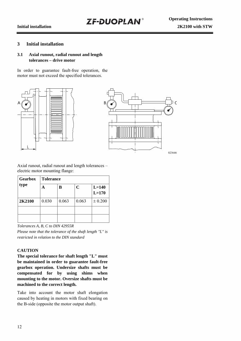
3.1 Axial runout, radial runout and length tolerances – drive motor
In order to guarantee fault-free operation, the motor must not exceed the specified tolerances.
Axial runout, radial runout and length tolerances – electric motor mounting flange:
Tolerance Gearbox type A B C L=140
L=170
2K2100 0.030 0.063 0.063 ± 0.200
Tolerances A, B, C to DIN 42955R Please note that the tolerance of the shaft length "L" is restricted in relation to the DIN standard
CAUTION The special tolerance for shaft length "L" must be maintained in order to guarantee fault-free gearbox operation. Undersize shafts must be compensated for by using shims when mounting to the motor. Oversize shafts must be machined to the correct length.
Take into account the motor shaft elongation caused by heating in motors with fixed bearing on the B-side (opposite the motor output shaft).
023646

Operating Instructions
2K2100 with STW Initial installation
3.2 Balancing
13
The hubs (2) come with a keyway (1) for transmitting power from the motor shaft (3) as standard.
There are two balancing types for the motor and gearbox, irrespective of the balancing quality: semi-key and full-key.
It must be ensured that the hub is balanced in the same way as the motor.
This is why it is very important to indicate the motor data, dimensions and balancing type when ordering.
Motor output shafts with standard fitted key in accordance with EN 50347: 2001
Gearbox type
Shaft diameter,
length
Fitted key
Fitted key length
2K2100 Ø 75x140 mm Ø 80x170 mm Ø 90x170 mm
A20x12A22x14A25x14
125 mm 140 mm 140 mm
NOTE In the case of motor shafts with open ends of the keyway, the parallel key is to be glued into the groove in order to avoid axial migration of the parallel key and/or the hub.
023647
1
2
3
Semi-key balancing Full-key balancing
3.2.1 Semi-key balancing
In semi-key balancing, the keyway is filled out with a balance compensator corresponding to approximately half a key, shape B by default. This is based on the original key, shape, length and position used by the motor manufacturer and is defined as a counterweight. In semi-key balancing – in contrast to full-key balancing – the joint passes through a shared component. This means imbalance can arise after assembly due to tolerance factors.
As a result, it is recommended that rebalancing should be performed after the joined parts have been assembled.
3.2.2 Full-key balancing
In full-key balancing, the motor shaft is balanced with a full key whereas the hub is not. The key, shape, length and position are not important in this case.

Operating Instructions
Initial installation 2K2100 with STW
3.3 Mounting of 2K2100 without STW (spur gear stage) on motor/gearbox
If the 2K2100 without output (without spur gear stage) is supplied, mount the gearbox as follows.
Clean the flange faces on the gearbox housing and the machine, check for unevenness and, if necessary, skim with an oil stone.
First check the following dimensions (see diagram):
A: 39 ± 0.1 mm is required on the input shaft in order to allow bracing of the planetary gear carrier with the machine bearings or spacer ring (1).
B: 41 – 0.5 mm; length of the profile in the planetary gear carrier
Installation:
14
Slide the planetary gear carrier (profile N90x2x30x44x9H) with ring gear onto the shaft with the profile W90x2x30x44x9k. Bolt the planetary gear carrier using the pan head screw "D" with hexagon socket head (M24x2x60, with bore).
Tightening torque: 420 Nm.
023648
Insert the O-ring "C" into the groove, using standard grease to affix it if necessary. First position the gearbox housing with the pan head screws (13xM16x*) "F" and then tighten the screws diagonally/alternately in several stages until the final torque (195 Nm) is reached.
Undo the brake disc bolts. The shift mechanism must be in 1st gear (4:1). Centering the brake disc relative to the sliding sleeve can influence the gear change.
NOTE:
The shift mechanism must be in 1st gear (position S; 4:1). As a result, the sliding sleeve is also guided. The gearing should be greased to make installation easier.
A
39.000
41.000
C
B
I
D
F
H
R
P
M
S
T G
N1
023649
* (not part of ZF scope of supply)

Operating Instructions
2K2100 with STW Initial installation
3.4 Adaptation, motor/gearbox
The motors must have a flange-mounting option for mounting the gearboxes.
The gearbox housings are fitted to the motor by means of the centering adapter (version without output). This is standard.
NOTE:
Option: in the case of the version with output shaft, the 2K2100 gearbox housing is adapted to the machine by means of centering on the bearing housing.
Different gearbox variants are used depending on the motor version. Gearbox mounting therefore differs accordingly.
Reference dimensions for hub position
Gearbox type Dimension C in mm
108.8 + 0.2
2K2100
15
Spacer discs "D" are supplied with shims of varying thickness. These enable balancing of the motor shaft length tolerances and, therefore, compliance with reference dimension "C".
3.4.1 Open design
The open version is the gearbox without adapter plate but with seal on the motor output shaft (2) to prevent gearbox oil ingress.
The drive hub (1) is delivered loose with the gearbox. Clean the fitting surfaces of the motor (3) and drive hub. Check the motor shaft for axial and radial runout as described in section 3. Also lightly grease the motor shaft.
After cleaning the fitting surfaces, heat the drive hub to approx 120 °C from the opening and slide it onto the motor shaft until it reaches the stop.
Then check the reference dimension "C". If undersize, use shims for balancing. If oversize, shorten the motor shaft.
CAUTION Risk of motor shaft damage if the hub is not sufficiently heated. The M10 set screw (9) is to be tightened with 34 Nm and must be secured against twisting, also refer to section 3.5. The factory-set sliding sleeve shift dimension can be checked as described in section 3.5 or 3.7.3.
NOTE
If the gearbox does not have an output, the gearbox must first be mounted onto the machine. (section 3.3)
The same applies in the case of the gearbox variant with additional pulley drive.
Dimension C 023650

Operating Instructions
Initial installation 2K2100 with STW
3.4.2 Closed design, on request (with shaft seal)
This variant incorporates an adapter plate (5) with shaft seal (7), which means that the gearbox forms a compact, closed unit.
The adapter plate (5) and drive hub (1) are separately delivered loose. Clean the fitting surfaces of the motor (3) and drive hub. Check the motor shaft (2) for axial and radial runout as described in section 3.1. Also lightly grease the motor shaft.
After cleaning the fitting surfaces, place the adapter plate with radial shaft seal (7) onto the motor housing. Heat the drive hub to approx 120 °C from the opening and slide it onto the motor shaft until it reaches the stop.
Then check reference dimension "C" and change using shims if necessary.
CAUTION Risk of motor shaft damage if the hub is not sufficiently heated.
Tighten the threaded pin (9) and secure it to prevent it from turning, see section 3.5. The factory-set sliding sleeve shift dimension can be checked as described in section 3.5.
CAUTION Grease the radial shaft seal and the drive hub before installation. When installing, make sure that the sealing lip and the radial shaft seal are in the correct position.
NOTE The radial shaft sealing ring must be removed on the A-side when the closed design is used.
Dimension C 023651
16

Operating Instructions
2K2100 with STW Initial installation
3.4.3 Open design with adapter ring for 2K2100, on request
The adapter ring allows adaptation to different connection dimensions. A seal is required on the motor output shaft.
The adapter ring (5) and drive hub (1) are delivered loose. Clean the fitting surfaces of the motor (3) and drive hub (1). Check the motor shaft (2) for axial and radial runout as described in section 3. Also lightly grease the motor shaft.
After cleaning the fitting surfaces, place the adapter ring onto the motor housing. Then heat the drive hub to approx 120 °C from the opening and slide it onto the motor shaft (2) until it reaches the stop.
Then check reference dimension "C" and change using shims if necessary.
CAUTION Risk of motor shaft damage if the hub is not sufficiently heated.
Tighten the threaded pin (9) and secure it to prevent it from turning, see section 3.5. The factory-set sliding sleeve shift dimension "Y" can be checked as described in section 3.5.
Dimension C
023652
17

Operating Instructions
Initial installation 2K2100 with STW
3.5 Mounting the gearbox
NOTE
When fitting the drive hub (1), screw in and tighten the threaded pin (9) onto the fitted key. Coat the threaded pin with liquid seal before installing it. Make sure that the O-ring (10) is in the correct position during installation. The O-ring is delivered loose with the gearbox and can be coated with grease before being inserted into the seal groove in the housing (6).
Check the position of the gearbox shift mechanism. The sliding sleeve (see section 3.7.3) must be in the "1" gear position ("low" gear ratio).
Take up the gearbox and place it onto the motor flange. Carefully bring the sun gear/hub connection together when doing this.
NOTE The external spline of the sun gear must be guided into the internal spline of the hub.
This can be made easier by turning to the left or right at the gearbox output.
The gearbox housing, adapter ring (if applicable) and motor are bolted together using four, six or eight hexagon bolts (11).
Fill the gearbox with oil and connect up the recirculating lubrication system and the power supply. The breather outlet must always be at the top, regardless of the installation position. Tighten by max. 1 turn if necessary.
The gearbox is now ready for use.
10 11 6
A
B
023653
1st gear position
A Brake disc B Sliding sleeve
CAUTION The gearboxes can be operated under the same degrees of protection as those defined for AC and DC motors. When setting up, make sure that the motor cooling air can flow in and out unhindered.
NOTE Before taking the electric motor/gearbox assembly into operation, check that the gearbox output can be turned by hand.
In the case of drive units that are fixed on the gearbox flange, support the motor on the B-side so that it does not vibrate.
18

Operating Instructions
2K2100 with STW Initial installation
3.6 Output as STW (spur gear stage) gearbox
Clean the entire mounting surface, machine and gearbox (including the surfaces for reaction members) (6), check for unevenness and, if necessary, skim with an oil stone.
Work on the 2K2100 with STW (spur gear stage) before mounting
Mount the oil line (1) (M16x1.5) on the spur gear stage housing because the lack of space will make subsequent installation impossible or very difficult.
Position the eccentric adjuster (2; 3) right at the bottom.
The maximum eccentricity is indicated by a marking (0) on the eccentric bolt.
On the left side (3), place the marking at the 2-4 o'clock position.
On the right side (2), place the marking at the 3-5 o'clock position.
This setting ensures that the intermediate gear is at the "lowest" position.
PORT FORLUBE OIL
PORT FORLUBE OIL
HOLLOWSCREW
023654
Mounting
Fix the gearbox (2K2100 + spur gear stage) on the motor frame with the centering ring (4) and attach using the pan head screws (M16x80; 15 pcs.) (5). Tighten to 195 Nm in 4 or more stages (50, 100, 150, 195 Nm). Lock the screws using Loctite.
Also mount the reaction member bolts (6) (not included in ZF scope of supply) (through-holes for M18 bolts), tighten them to the correct tightening torque and lock them.
19

Operating Instructions
Initial installation 2K2100 with STW
Clean the main spindle (page 19/7) in the area of the helical gear (page 19/8) and remove any oil. The bore (Ø 250 mm) in the helical gear must be cleaned and free of oil. Apply a light film of oil to the conical surfaces of the helical gear and the two tensioning rings (do not use grease/oil containing MoS), otherwise there will be a cold-welding effect when bracing. Slide the helical gear onto the main spindle with the two tensioning rings and align on the intermediate gear of the spur gear stage. Then tighten the helical gear clamping bolts (M8x130; 8 pcs.) slightly (by hand, 5 - 10 Nm), check the alignment of the helical gear and check that the two tensioning rings are seated at right angles. Evenly tighten the bolts to the specified tightening torque in 4 stages, working cross-wise (10, 20, 30, 35 Nm).
Check the tightening torque of the bolts in the order of their arrangement. Installation of this component is not complete until it is no longer possible to tighten any of the bolts.
NOTE After leaving the clamping bolts to "settle" for at least 8 hours, retighten them again. Check the tightening torque of the bolts in the order of their arrangement.
Option:
Tensioning ring for additional drive (C-axis drive)
Carry out the preparation work and installation of the tensioning ring in the same way as for the helical gear.
If there is an additional tensioning ring for C-axis drive, install the clamping elements in the same way as the clamping elements for the helical gear on the main spindle.
Eccentric adjustment of the intermediate gear
After installing the helical gear on the main spindle, adjust the intermediate gear using the eccentric bolt. The backlash between the helical gear (8) and the intermediate gear or intermediate gear and input helical gear must be between 0.05 and 0.1.
NOTE Check the backlash using a feeler gauge.
Procedure:
First turn the right eccentric bolt (2) clockwise until a slight resistance can be felt. Then turn the left eccentric bolt (3) counter-clockwise until a slight resistance can be felt.
Main spindle
Helical gear
Intermediate gear
Page 19/20
Input gear
023738
Keep repeating this procedure until no further adjustment can be completed.
Then tighten the mounting bolts (page 19/9) on the eccentric bolt to a torque of 23 Nm. Lock the bolts using Loctite.
Also tighten the clamping bolts (page 19/10) (M12x145; 2 pcs., tightening torque 79 Nm).
Fix and tighten the cover (page 19/11) with seal (page 19/12) (M8x16; 16 pcs., tightening torque 23 Nm).
Mounting of the end cover (page 19/13).
Align with the labyrinth ring (not part of ZF scope of supply) (page 19/14), tighten using the 6 pan head screws (page 19/16) (M12x30) and then pin with the supplied taper pins (page 19/15). In order to allow easier determination of the cover position with the pan head screws (M12x30; 6 pcs., tightening torque 23 Nm) during subsequent removal.
3.6.1 Option: version with belt drive
The pulley must be centered on the outer diameter of the input flange (page 30/17) (tolerance K6), fastened with the bolts so that it is frictionally engaged and secured. Comply with the specified tightening torques.
20

Operating Instructions
2K2100 with STW Initial installation
The pulley should be balanced to quality 6.3 as per VDI Directive 2060 and DIN ISO 1940 Part 1 + Part 2 in order to ensure low-vibration operation. Note the axial and radial runout of the centering device on the belt pulley and belt grooves in relation to the centering device.
CAUTION Note the maximum specified tensioning force when tensioning the belts in order to prevent bearing overload.
The average belt force must be between the bearings. When assembling, it must be possible to easily slide the pulley onto the output flange. Heat the pulley if necessary.
21
3.6.2 Option: version with coaxial output, only on request
In the case of the version with coaxial output (shaft stub), also note the balancing type for the output (see section 3.2).
3.7 Electrical connection, gearchange
The gearbox is electrically connected using the supplied 8-pole Harting connector (HAN 8 U). The plug-in connection is located on the shift unit.
3.7.1 Shift unit
Technical data:
Power consumption 85 W
Supply voltage 24 V DC ± 10%
Current consumption 5 A (max. pull-in current)
The required cable lead diameter is 1.5 mm².
The 24 VDC supply voltage and 5 A current consumption must be assured at the shift unit plug on the gearbox.
Losses due to cable length and transition resistors must be taken into account.
If switching to the shift unit by relay, we recommend using a varistor, e.g. Siemens type S14-30 (30 V) to connect to the 24 V voltage pin 2 and pin 3.
Scope of supply:
Sleeve housing, screw connection, socket insert and 8 jacks, type Harting AWG16, (ZF order no. 4161 298 004).
The shift unit can only be obtained as a complete part.
Gearbox shift mechanism:
During transmission stage changeover, the main spindle motor performs a pendulum motion with a 4° - 6° angle with 1 to 5 changes in rotary direction per second. Major pendulum motion may lead to damage at the meshing gears.
In average, this means: nMot = 5°/s = 5° 60/min = 300°/min = 300/360 rpm = 0.83 rpm.
Conversion Pendulum speed ↔ pendulum rotary motion
Speed [rpm]
Angle [°/min]
Time [sec]
Angle [°/sec]
0.25 90 3.33 5
0.50 180 1.67 5
1.00 360 0.83 5
2.00 720 0.42 5
3.00 1080 0.28 5
4.00 1440 0.21 5
5.00 1800 0.17 5
The machine optimum is to be determined on the basis of shift tests in relation to the different masses and thereto connected drag torques of the spindle.

Operating Instructions
Initial installation 2K2100 with STW
In most cases, however, the engaging gears in the gearbox mesh as early as the first rotation direction change, meaning that the shift time is around 300 to 400 milliseconds. Mechanical gear changes are performed by a shift unit on the gearbox, driven by a 24V DC motor.
The gearbox shift components (axially moved, toothed sliding sleeves) are positively engaged.
The shift positions are monitored by limit switches in the shift unit. A time relay must be provided to monitor the time lapse, i.e. if a shift is not performed within 2 seconds from the beginning of the shift, it is cancelled (if no signal is received from the limit switch S1 or S2). A new shift then has to be initiated. A time limit of 10 seconds must be provided for around 4 to 5 further shift attempts. If the gear change does not take place within this time, the system has to be checked. Check the oscillating movement (angle) and the number of rotation direction changes. In most cases, adjust based on the smaller value and then repeat the shift attempt.
Shifting at low speed without oscillation is not permitted as a perfect change cannot be assured (flowchart for gear change, see section 3.7.6).
CAUTION Once the limit switch signals are reached, there should be a waiting time of 0.5 to 1.0 seconds before the main spindle motor is enabled. The limit switch signals must be monitored during the operating time.
The limit switches must only be energized with the control current (0.5 A) and not with the change current (5 A).
The shift sequence must be monitored. If necessary, a timer should be used to cancel the shift sequence after approx. 2 seconds if there is no limit switch signal (S1/S2). After this, new shift command; main spindle motor may not be enabled.
Diagram for shift unit with three positions (with neutral position):
1st gear ==> e.g. 4:1
2nd gear ==> 1:1
3rd gear ==> Neutral position, idling
3.7.2 Checking, adjusting and exchanging the shift unit on the 2K2100 gearbox
The numbers on the drawing are the same as those used in the text.
Position shown (switch S1 actuated) corresponds to 1st gear. Neutral position switch not illustrated.
Gear 1
Gear 2
023655
22

Operating Instructions
2K2100 with STW Initial installation
023656
3.7.3 The cover (item 082) is removed from
the shift unit for checking all functions
Check the motor function by changing from 1st to 2nd gear and back several times.
NOTE When doing this, please press lightly on the selector shaft (item 010) at the point where the bolt (item 690) is located – e.g. using the handle of a screwdriver.
3.7.4 Checking the slip clutch for the correct friction torque
The slip torque should be set at 5 to 6 Nm. If the slip clutch setting is not sufficient, the shift travel of the shift fork will not be sufficient to reach the end position, the engine will continue turning and the clutch will slip. If this is the case, check the hexagon nut (item 870) for firm attachment and, if necessary, retighten and secure it.
023657
3.7.5 Checking the limit switches
1st gear limit switch setting:
Use a screwdriver to turn the worm shaft to the right until the shift fork is at the 1st gear limit stop (resistance can be felt). Limit switch S1 must be audibly actuated in this position. If this is not the case, loosen the threaded pins (item 840) and use the screwdriver to push 1.5 to 2 mm past the limit switch switching point (overrun to ensure the switching function).
2nd gear limit switch setting (i=1.00):
Use a screwdriver to turn the worm shaft to the left until the shift fork is at the 2nd gear limit stop (resistance can be felt). Limit switch S2 must be audibly actuated in this position. If this is not the case, adjust the shifting segment as described for 1st gear.
Apply locking paint on the threaded pins (item 840).
23

Operating Instructions
Initial installation 2K2100 with STW
3.7.6 Shift logic for 1st and 2nd gear d gear
Reduce main spindle motor speed
from operating speed to zero. Leave controller enable on
converter.
Apply desired oscillating speed to converter and speed controller
without delay. 1)
Servomotor for gear ratio change ON (pin 2 and 3)
Gear ratio change is completed within 2 seconds (acknowledgement from limit switch S1 or S2 from the
shift unit)
Shut off desired oscillating speed.
Servomotor OFF after 0.5 to 1.0 seconds.
Gear ratio change complete.
Number of attempted shifts > 5 each
from the starting position (polarity reversal)
Gear ratio change not successful: Switch off main spindle motor.
Check system.
N
N
Y Y
Main spindle motor start after min. 0.5 seconds.
1) Alternatively, the first switching test can be performed without oscillating, but this requires a de-energized main spindle motor or minor output-end masses.
24

Operating Instructions
2K2100 with STW Initial installation
3.7.7 Shift logic for centre position e position
Reduce main spindle motor speed from operating speed to zero.
Leave controller enable on converter.
Apply desired oscillating speed to converter and speed controller
without delay.
Servomotor for gear ratio change ON
25
Gear ratio change is completed within 2 seconds (acknowledgement from limit switch S1 or S2 from the
gearbox shift unit)
Shut off desired oscillating speed.
Gear ratio change ended in neutral centre position.
Query centre position via pin 5 and 7.
Does the gear ratio change last
longer than 10 seconds?
Gear ratio change not successful: Switch off main spindle motor.
Check system.
N
N
Y Y
Servomotor back to starting position
Main spindle motor start after min. 0.5 seconds.

Operating Instructions
Initial installation 2K2100 with STW
3.8 Lubrication
3.8.1 Recirculating lubrication
NOTE
The 2K2100 gearbox must always be operated with recirculating lubrication. In this case, the oil level is not visible in the oil sight glass (max. oil spray).
CAUTION Before operation for the first time, always ensure that the gearbox oil supply is taken into operation first. To do this, check the oil level in the reservoir and, if necessary, top up with oil until the oil level is no longer below the minimum mark in the reservoir.
The pump and oil tank components must be arranged below the gearbox oil level (outlet bore).
NOTE After switching off the machine, check that the oil level in the reservoir does not rise above the maximum mark.
The diagrams on page 27 show the oil inlet and outlet points on the gearbox. Please refer to the relevant installation drawings for precise details.
The following instances are no cause for concern:
• The oil level in the tank falls due to foaming of the gearbox oil in the gearbox during operation.
• An oil-air emulsion is formed in the oil return and in the tank.
3.8.1.1 Recirculating lubrication for V1/B5 operation
Refer to section 3.8.2 for the position of the oil inlets and outlets.
Oil inlet quantity:
Inlet for 2K2100: (M) at least 3.0 l/min at 3 bar, thread M16x1.5 (hollow screw).
Inlet for spur gear stage: (K) approx. 3.5 l/min, at 3 bar, on eccentric bolt (3), thread M12x1.5.
The outlet line (D) (thread M42x2) should be dimensioned so as to prevent oil return blockages in the gearbox. (Di approx. 20 mm)
3.8.1.2 Recirculating lubrication with heat exchanger and intermediate tank
A heat exchanger is installed in the recirculating lubrication system to ensure additional temperature reduction.
The tank volume should be at least ten times the recirculating oil quantity in order to ensure effective oil cooling.
NOTE: To prevent gearbox damage due to lack of oil, ZF Maschinenantriebe GmbH recommends you install an oil level sensor at the intermediate tank.
A 60 µm filter must be used at the gearbox oil inlet.
Cooler
Filter
Pump
023658
26

Operating Instructions
2K2100 with STW Initial installation/Maintenance
3.8.2 Ports and connections for lubrication
3.8.2.1 2K2100 with STW (spur gear stage)
023659
Installation position Oil inlet port 2K2100 with STW
Max. pressure Oil return port
B5
M at least 3.0 l/min and K at least 2.5 l/min
3 bar 5 bar
E or F or D
V1 M at least 3.0 l/min and K at least 2.5 l/min
3 bar 5 bar
D or E or F
NOTE The principal factor in determining the oil supply volume is always the volume which flows out of the oil return at least.
27

Operating Instructions
Initial installation 2K2100 with STW
3.8.2.2 2K2100 – direct mounting on headstock or version with output
024878
Installation position Oil inlet port 2K2100 with STW
Max. pressure Oil return port
B5
M at least 3.0 l/min and K at least 2.5 l/min
3 bar 5 bar
E or F or D
V1 M at least 3.0 l/min and K at least 2.5 l/min
3 bar 5 bar
D or E or F
NOTE The principal factor in determining the oil supply volume is always the volume which flows out of the oil return at least.
28

Operating Instructions
2K2100 with STW Taking into operation/Maintenance
4 Taking into operation 5 Maintenance
4.1 Initial inspection 5.1 Oil change
Check that the gearbox is correctly installed before taking it into operation. Oil change interval: every 5000 operating
hours • Mechanical fastening
• Motor flange-mounting ENVIRONMENTAL HAZARDS! !Lubricants and cleaning products must not be poured onto the ground, into groundwater or down the drain.
• Gearbox oil ports and connections
• Oil supply/oil fill assured • Obtain and comply with the safety
regulations relevant to these products issued by your local environmental authority.
• Electrical connections
• Ease of movement (can be turned by hand)
• Breather vertical position • Collect used oil in a suitably large
container.
• Dispose of used oil, clogged filters, lubricants and cleaning products in accordance with local environmental protection regulations.
• Always follow the instructions issued by the manufacturer when handling lubricants and cleaning products.
Drain used oil at operating temperature into a suitable container and remove from the pump reservoir.
The drain ports differ depending on the installation position and gearbox version (see section 3.8.2).
Add new gearbox oil via the oil tank/reservoir. After taking the pump into operation, check the oil level continuously and top up if necessary.
The oil level itself is all-important. The oil quantity in liters indicated on the model plate is a reference value only.
Let the oil pump operate briefly after filling with oil to remove any air and top up with oil again if necessary.
29

Operating Instructions
Repair 2K2100 with STW
30
6 Repair
In the event of gearbox malfunctions, first check the connected components and their ports and connections.
Carefully describe the type of fault so as to assist manufacturer diagnosis (see section 6.1).
Repairs on the gearbox itself may only be carried out by ZF Maschinenantriebe GmbH or by authorized ZF after-sales points.
6.1 Gearbox fault checklist
If you encounter drive unit faults, please refer to the remedies in section 7 first of all for help.
If this does not solve the problem, you will need to provide the following information for diagnosis at ZF Maschinenantriebe GmbH or an authorized ZF after-sales point:
Gearbox data on the model plate
Typ: . . . (Type)
Stückliste: . . . . . . . . . . (P.L.No.)
Serien-Nr.: . . . . . . (Serial-No.)
Motor data on the model plate
Manufacturer: . . .
Type/size: . . .
Questions for fault diagnosis:
• Is gearbox oil sight glass dark/discolored black?
• Smell of burning oil at oil breather?
• Gearbox running noise in 1:1 or 4:1 gear ratio, or only in one rotation direction or in both rotation directions?
• Before the running noise occurred, was the machine operated in only one gear ratio (1:1) for an extended period of time?
• Did the running noise occur after changing the machine's cycle or was the machine cycle unchanged?
• Was any maintenance carried out on the machine before the fault occurred and, if yes, what did this maintenance work involve?
• No gear change or gear loss in the event of a shift problem?
• Does shift logic conform to ZF specifications? (see section 3.7.6 and section 3.7.7)
• What is the voltage at the gearbox changeover during the shift sequence?

Operating Instructions
2K2100 with STW Repair
6.2 Gearbox removal
(based on the example of the version with adapter plate and shaft seal)
Proceed accordingly in the case of other versions.
• Switch off the machine
• Switch off the power supply
• Disconnect the electrical connections
• Disconnect the gearbox oil connections, drain the gearbox oil
• Undo the mounting bolts (11)
• Pull the gearbox (6) off the adapter plate (5) and drive hub (1)
6.3 Hub
• Undo the threaded pin (9) used to radially secure the fitted key
• Use a removing device, e.g. three-arm puller, to pull off the drive hub against the motor shaft without heating the hub.
Dimension C 023718
1 Drive hub
2 Motor shaft
3 Motor
4 Adapter plate
5 Gearbox housing
6 Shaft seal
7 Threaded pin
8 O-ring
9 Mounting bolt (gearbox-adapter)
10 Mounting bolt (adapter-motor)
31

Operating Instructions
Frequently Asked Questions (FAQs) 2K2100 with STW
32
7 Frequently Asked Questions (FAQs)
Fault Cause of fault Remedy
Gearbox is loud, knocking noises
• Loose contact on motor speed sensor, which causes permanent motor governing
• Speed sensor dirty, no clear signals sent
Check speed sensor and electrical lines to motor, clean/exchange speed sensor as necessary.
Check motor management system, adjust speed control accordingly ("softer" setting)
Gearbox is loud, running noise Long periods at high cutting speed in ratio 1:1 followed by change to machining in ratio 4:1
No gearbox damage
Gearbox running noise normalizes after several gear changes
Gearbox is loud, running noise in ratio
Motor shaft is too long, axial bearing damaged
Check bearing, install new bearing if necessary
Gearbox leaking at gearbox input/output
Defective seals Renew seals, send gearbox to ZF for inspection if necessary
Gearbox leaking at breather • Oil has aged
• Too much oil added during oil change
• Change the oil
• Check the oil level and correct if necessary
Machine control receives no shift position signals from the gearbox shift unit
• Loose contact in the plug connection on the gearbox shift unit
• Fault in the shift unit
• Check the plug connection and clean if necessary, secure connectors using clips
• Send gearbox to ZF for inspection

Operating Instructions
2K2100 with STW Frequently Asked Questions (FAQs)
33

ZF Friedrichshafen AG
Group Headquarters
D-88038 Friedrichshafen
Tel.: ++49 75 41 77-0 Fax: ++49 75 41 77-90 8000
www.zf.com