Operating Instructions MCP Multichannel Pipette ... · Getting to know the MCP 7 1.3 Safety has...
54
Operating Instructions METTLER TOLEDO MCP Multichannel Pipette Calibration Systems
Transcript of Operating Instructions MCP Multichannel Pipette ... · Getting to know the MCP 7 1.3 Safety has...

Operating Instructions
METTLER TOLEDOMCP Multichannel Pipette Calibration Systems

Overview of the MCP
A
C
13
14 15
16
17
18
19
20
1
2
3
4
5
6
7 8 9
10
11
12
B
D
21
2224
23

Figure A: Overview 1 Evaluationunit(fordetails,seefigureD) 2 Motorcontrolunit 3 Measuringunit(fordetails,seefigureC)
Figure B: Connections(backoftheinstrument)Evaluation unit: 4 CANsocket(connectiontothemotorcontrolunit) 5 DB-25socket,female(connectiontothemeasuringunit) 6 ConnectionsocketforACadapter
Motor control unit: 7 9-pinD-SUBsocket,female(connectiontothePCviaconverter/hub) 8 CANsocket(connectiontotheevaluationunit) 9 15-pinD-SUBsocket,female(connectiontothemeasuringunit)10 ConnectionsocketforACadapter
Measuring unit: 11 15-pinD-SUBsocket,female(connectiontothemotorcontrolunit)12 DB-25socket,female(connectiontotheevaluationunit)
Figure C: Detailed view of the measuring unit 13 Levelingscrew14 Rackwithcontainers15 Slideforrackcover 16 Rackcover 17 Levelindicator18 Housingwithweighingcellandtransportmechanism 19 Weighingyoke 20 Racksupport
Figure D: Detailed view of the evaluation unit 21 Statusindicatorsforvibrationadapter,weighingprocessadapterandrepeatability(fromlefttoright) 22 Alphanumericdisplay(weightvalue,menu,messages) 23 Calibrationsymbol(appearswhenweighingcellrequirescalibration)24 Operatorkeyswiththefollowingfunctions:
In measuring mode:
Press briefly Press and hold down
«1/10d»,«Cal» Changethedisplayresolution Internalcalibrationoftheweighingcell
«j»,«Menu» Nofunction Callthemenu
«Start»,«f» Startmeasuringcycleorreferencemeasurement Triggerareferencemeasurement
«On/Off»,«k»,«C» SwitchontheMCPCancelaprocessinprogressSetthedisplaytozero
SwitchofftheMCP
In the menu:
Press briefly Press and hold down
«1/10d»,«Cal» Nofunction Nofunction
«j»,«Menu» Selectthenextmenuitem Exitthemenuafterstoringthesettings
«Start»,«f» Changethesetting Nofunction
«On/Off»,«k»,«C» Exitthemenuwithoutstoring Nofunction
Contents
4
Contents1 Getting to know the MCP ................................................................................................................................. 6
1.1 Introduction................................................................................................................................................................. 61.2 Whatyoushouldknowabouttheseinstructions............................................................................................................ 61.3 Safetyhaspriority........................................................................................................................................................ 7
2 Standard equipment ........................................................................................................................................ 8
2.1 Contentsofthelargetransportcase............................................................................................................................. 82.2 Contentsofthesmalltransportcase............................................................................................................................. 92.3 Othercomponentssupplied......................................................................................................................................... 9
3 System setup and cabling ............................................................................................................................. 10
3.1 Selectingthelocation................................................................................................................................................ 103.2 Assemblingandlevelingthemeasuringunit............................................................................................................... 103.2.1 PreparingtheMCPfortheverificationofmultichannelpipettes.................................................................................... 103.2.2 PreparingtheMCPforthecalibrationofsingle-channelpipettes.................................................................................. 123.2.3 Levelingthemeasuringunit........................................................................................................................................ 133.3 Systemcabling.......................................................................................................................................................... 14
4 Startup and menu settings............................................................................................................................. 15
4.1 SwitchingtheMCPonandoff..................................................................................................................................... 154.2 Menuoverview........................................................................................................................................................... 154.3 Usingthemenu......................................................................................................................................................... 164.4 Settingthevibrationadapter....................................................................................................................................... 174.5 Settingtheprocessadapter........................................................................................................................................ 174.6 Selectingrepeatability................................................................................................................................................ 174.7 Selectingthenumberofpipettechannels................................................................................................................... 174.8 Activating/deactivatingthesecondmeasurementofcontainer1.................................................................................. 184.9 Definingthefilllimitofthecontainers......................................................................................................................... 184.10 Definingthetimeintervalforreferencemeasurement.................................................................................................. 184.11 Calibratingthecontainers.......................................................................................................................................... 194.12 Resettingtofactorysettings........................................................................................................................................ 19
5 Working with the MCP .................................................................................................................................. 20
5.1 Calibratingtheweighingcell...................................................................................................................................... 205.2 Preparingtheworkstation.......................................................................................................................................... 205.3 Testingmultichannelpipettes..................................................................................................................................... 215.3.1 Fillingthemoisturetrap.............................................................................................................................................. 215.3.2 Referencemeasurement............................................................................................................................................ 215.3.3 Performingthemeasurement..................................................................................................................................... 225.3.4 Emptyingthecontainers............................................................................................................................................. 235.4 Testingsingle-channelpipettes................................................................................................................................... 245.4.1 Fillingthemoisturetrap.............................................................................................................................................. 245.4.2 Performingthemeasurement..................................................................................................................................... 24
6 Status and error messages ............................................................................................................................ 26

Contents
7 Cleaningandservice.................................................................................................................................... 28
8 Technicaldataandaccessories..................................................................................................................... 29
8.1 MCP105data............................................................................................................................................................. 298.2 Ambientconditions.................................................................................................................................................... 298.3 Protectionandstandards............................................................................................................................................ 298.4 Powersupply............................................................................................................................................................. 308.5 RS232Cinterfacedata............................................................................................................................................... 308.6 Dimensionsandweights............................................................................................................................................ 318.7 MCPtechnicalspecifications...................................................................................................................................... 328.8 Accessories............................................................................................................................................................... 328.9 Spareparts................................................................................................................................................................ 33
9 Appendix:MCPandhostcomputer................................................................................................................ 34
9.1 Connectiontothehostcomputer................................................................................................................................ 349.2 PCsoftware............................................................................................................................................................... 359.2.1 PCsoftwarefunctions................................................................................................................................................. 359.2.2 Initializationandconfigurationofthemeasuringsystem.............................................................................................. 369.2.3 Measurementprocedure............................................................................................................................................ 379.2.4 Abortingareferencemeasurement............................................................................................................................. 389.2.5 Abortingapipettemeasurement................................................................................................................................. 409.3 Dataformat............................................................................................................................................................... 429.4 MTSICScommands................................................................................................................................................... 429.4.1 Notesonthecommandformat................................................................................................................................... 429.4.2 StandardSICScommands.......................................................................................................................................... 439.4.3 SpecificSICScommandsfortheMCP.......................................................................................................................... 43
10 Recommendationsforpracticaluse............................................................................................................... 49
10.1 Internalcalibration..................................................................................................................................................... 4910.2 Verificationoftheweighingcellcalibration................................................................................................................. 4910.3 Excessevaporation.................................................................................................................................................... 49
11 Workingwiththeoptionalcalibrationkit........................................................................................................ 0
11.1 Contentsofthecalibrationkit..................................................................................................................................... 5011.2 Installationofthecalibrationkit.................................................................................................................................. 5011.3 Carryingouttheverification........................................................................................................................................ 51

GettingtoknowtheMCP
6
1 Getting to know the MCPThissectionprovidesbasicinformationaboutyourMCPmultichannelpipettecalibrationsystem.Pleasereadthissectioncarefully,evenifyoualreadyhaveexperiencewithsimilarsystemsandbesuretofamiliarizeyourselfwiththesafetyinstructions.
1.1 IntroductionThankyouforchoosingtheMCPfromMETTLERTOLEDO.
TheMCPenablesyoutodeterminetheprecisevolumeofpipetteswithoneormorechannels(max.12channels).Todothis,theMCPdeterminestheamountofwaterpipettedforeachchannelandtransfersthisdatatoacomputer,whereitisconvertedintovolumevaluesandprocessedfurther.AspecialapplicationisavailablefromMETTLERTOLEDOforevaluatingthedata,however,theMCPcanalsobeintegratedintoexistingapplications.
TheMCPsupportspipettecalibrationinaccordancewithcommonstandards(suchasISO 8655)whileconsiderablyreducingthetimerequiredforthemeasuringsequence.SeveralMCPcanbecombinedwithoneanothertospeeduptheoperatingsequencefurther.WithanarrayoffiveMCPforexample,thecalibrationofa12-channelpipetterequireslessthanaquarterofanhour(threevolumeswith10measurementseach,accordingtoISO8655).
Thebuilt-inmoisturetrapandanadditionalmeasurementtocompensateforevaporationreducemeasurementerrors,whichcanoccurduetoevaporationofthemediumduringthemeasuringcycle.
TheMCPissuitableformobileuse:Allsystemcomponentsarehousedinastabletransportcase,whichprovidesoptimumprotec-tion.
1.2 What you should know about these instructionsThefollowingconventionsapplytotheoperatinginstructionsasawhole:
Keydesignationsareenclosedindoubleanglebrackets(e.g.«On/Off»or«f»).
Thesesymbolsindicatesafetyandhazardinstructions.Ifthesearenotcompliedwith,injurytotheuser,damagetotheMCPorothertangiblesandmalfunctionscanresult.
Thissymbolindicatesadditionalinformationanddirections,whichifobserved,facilitateyourhandlingoftheMCPandcontributetoproperandeconomicaluseofthesystem.

GettingtoknowtheMCP
7
1.3 Safety has priorityOperateandusetheMCPonlyaccordingtothedirectionsintheseoperatinginstructions.
ItisessentialtofollowthestartupinstructionsfortheMCP.
If the system is not used according to the manufacturer’s operating instructions, the instrument protection provided may be impaired (see also section 5.4.4 of EN 60101:01).
TheMCPmayonlybeusedinclosedrooms.Operationinhazardousenvironments isnotpermitted.
OnlyusetheACadaptersuppliedwiththeMCPandensurethatthevoltagevaluesprintedonitcorrespondtothelocallinevoltage.Onlyconnecttheadaptertosocketswithgroundconnection.
All components of the MCP have a rugged construction, but are still precisioninstruments.Treatthemwithappropriatecare.
DonotopenthecomponentsoftheMCP,theydonotcontainanypartsthatcanbemain-tained,repairedorreplacedbytheuser.ShouldyouhaveproblemswithyourMCPontheoddoccasion,pleasecontactyourresponsibleMETTLERTOLEDOdealer.
OnlyuseoptionalequipmentandperipheralssuppliedbyMETTLERTOLEDOwiththeMCP;thesehavebeendesignedtoworkoptimallyinthesystem.
Disposal
InconformancewiththeEuropeanDirective2002/96/EConWasteElectricalandElec-tronicEquipment(WEEE)thisdevicemaynotbedisposedofindomesticwaste.ThisalsoappliestocountriesoutsidetheEU,pertheirspecificrequirements.
Pleasedisposeofthisproductinaccordancewithlocalregulationsatthecollectingpointspecifiedforelectricalandelectronicequipment.
Ifyouhaveanyquestions,pleasecontacttheresponsibleauthorityorthedistributorfromwhichyoupurchasedthisdevice.
Shouldthisdevicebepassedontootherparties(forprivateorprofessionaluse), thecontentofthisregulationmustalsoberelated.
Thankyouforyourcontributiontoenvironmentalprotection.

Standardequipment
8
2 Standard equipmentFollowingreceiptoftheMCP,youshouldfirstcheckthescopeofdelivery.Ifthisdoesnotcorrespondtoyourorderorthedeliverynote,pleasecontacttheresponsibleMETTLERTOLEDOdealer.TheillustrationsinthissectionalsoshowyouthecorrectwaytopackallthepartsshouldyoueverneedtotransporttheMCPtoanotherlocation.
2.1 Contents of the large transport caseTheMCPissuppliedinaruggedtransportcase,whichreliablyprotectsthesystemcomponentsduringtransport.
1 Smalltransportcase(forcontentsseesection2.2)
2 Evaluationunit
3 Motorcontrolunit
4 Measuringunit
5 Rackwithmountedrackcoverandslide
10
9
9
1
4
5
6
7
2
8
3

Standardequipment
9
6 Racksupport
7 ACadapterforevaluationunit(primary:230 VACor115VAC,50/60Hz;secondary:12VAC)includingwallmountingplate
8 Cablesetconsistingof:
2powercablesfortheACadaptersoftheevaluationunitandthemotorcontrolunit.Ifthescopeofdeliveryincludesasuctionpump(item10),anadditionalpowercableissupplied.
1balancecable(connectioncableforevaluationunit/measuringunit60 cmlong,25-pin,m/m)
1CANcable(connectioncableforevaluationunit/motorcontrolunit30cmlong,m/m)
1controlcable(connectioncableformotorcontrolunit/measuringunit60cmlong,15-pin,m/m)
1USB/serialconverter
9 ACadapterformotorcontrolunit(primary:100-240 VAC,50/60Hz,0.8A;secondary:12VDC,2.25A).Ifthescopeofdeliveryincludesasuctionpump(item10),anadditionalACadapterforthepumpissupplied.
10 Single-channelsuctionpumpforemptyingthecontainers(Note:ForsystemsthatincludeseveralMCP,onlyonesingle-chan-nelsuctionpumpissupplied).Anoptional4-channelsuctionpumpisavailabletoincreaseefficiencywhenemptyingthecontainers,seesection8.8.
2.2 Contents of the small transport caseThesmalltransportcaseishousedinthelargecaseandcontainsthefollowingparts:
11 Containers(13pieces)
12 Waterreservoirwithcoverandholder
13 Weighingyoke(Caution:Donotsqueezetheyokewhenremovingfromthecase!)
14 Single-channelkit (parts insidethe dashed red frame). Afterinstallation of this kit the MCPis ready for the calibration ofsingle-channelpipettes.
15 Smallparts(rubberconeforremovingtheglasstubesofcontainers,tubesforthesuc-tionpump,etc.)
2.3 Other components suppliedAUSB/serial converterincludingdriversoftwareandinstructionsisalsosuppliedwitheachMCP.ThiscanbeusedtoconnecttheMCPtoaPCusingaUSBinterface.ForsystemsthatincludeseveralMCP,aUSB hubisalsosupplied(includingapowersupplywithamainsplugadaptorspecifictothecountry).EachMCPinthesystemisconnectedtothehubviatheUSB/serialconverter,whichinturnisconnectedtothePC(Note:Dependingonthecurrenttechnologyusedandavailability,ahubwithanintegratedUSB/serialconvertermaybesupplied).Alternatively,eachMCPcanbeconnecteddirectlytoanRS232CinterfaceonthePC.
Dependingonthescopeofyourorder,thedeliverymayincludeotheroptionalitems,whicharenotlistedabove(e.g.,PCsoftware,calibrationkitforthecontrolofinspection,measuringandtestequipment,etc.).
11
12
13
14
15

Systemsetupandcabling
10
3 System setup and cablingThissectionprovidesinformationaboutsettingupandselectingthelocationfortheMCP.
3.1 Selecting the locationPleaseobservethefollowingnoteswhenselectingasuitablelocation:
– Dry,closedroom
– Stable,vibration-freeandhorizontalsurface
– Nostrongfluctuationsintheambienttemperatureoratmospherichumidity.For good results the ambient humidity should be in the range of 50 - 60 % rh.Nodrafts(windows,doors,airconditioningunits,extractionhoods,etc.)andnodirectsunlight.
– Operationinhazardousenvironmentsisnotpermitted
3.2 Assembling and leveling the measuring unitTheevaluationunitandmotorcontrolunitaresuppliedreadyforcablinganddonotneedtobemounted.Themeasuringunitconsistsofdifferentcomponentswhichmustbeassembled.Therearetwoassemblyprocedures,oneforthecalibrationofmultichannelpipettesandoneforsingle-channelpipettes.Thenexttwosectionscoverbothproceduresseparately.
3.2.1 Preparing the MCP for the verification of multichannel pipettes
Placethemeasuringunitattheselectedlocation.
Inserttherack supportinthefrontposition(towardsthefrontpanel)inthemeasuringunit(A).Thepinontheracksupportmustbeontheright-handside(B).Note:Iftheracksupportisnotinstalledcorrectly,itwillnotbelevelandtheMCPwillnotworkproperly.
Duringtransportation,theweighing yoke support of the mea-suring cellmaybecomemisaligned,i.e.itisnotlocatedinthecenteroftheopeninginthemeasuringunit.Inthiscase,useasmall item (thinpencil, clipor the like) to center theweighingyokesupportagain.
B
A

Systemsetupandcabling
11
Carefullytaketheweighing yokeoutofthesmalltransportcase.Handletheweighingyokeasshownintheoppositefigure(left)andmakesurenottosqueezeit!
Carefullyinserttheweighing yokeintheopeningprovidedinthebaseofthemeasuringunit.Important: Alargeandsmallpinarelocatedatthefootoftheweighingyoke,whichcentertheyokeintheweighingcell.Ensurethatbothpinsareinthecorrespondingholesintheweighingcell.
Carefullyinserttherackintheracksupport.Therackonlyengagescorrectlyinthecamontheracksupportwhenbothslotsareontheright-handside.Wheninsertingtherack,ensurethattheweighingyokeremainsinitsplace.
Placethe12containersintherack.Ensurethattheconicalcenter-ingspigotsofthecontainersareontheoutsideoftheindentedguiderailonbothsides.

Systemsetupandcabling
12
Placetherack coverontherack.Thecamonthesideofthecovermustpoint towards the rightandengage in thecorrespondingslotontherack.
Placetheslideontherackcover.Ensurethatthecamsontheslideengageinthecorrespondingslotsontherack.Theillustra-tionoppositeshowstheslideintheopenstatewithfreeaccesstothecontainers.Tosealthefilleropenings,holdtheslideonthetabandslideittotheleft.
Note:Theslidecanalsobemountedata180°angle,thusenablinguser-friendlyoperationforrightandleft-handedusers.
Levelthemeasuringunit(seesection3.2.3).
3.2.2 Preparing the MCP for the calibration of single-channel pipettesThecalibrationofsingle-channelpipettesrequirestheso-called“single-channel kit”.Youwillfindtherespectivepartsinthesmalltransportcase(seesection2.2).Incasethesepartsarenotincludedinthestandarddeliveryyouwillhavetoorderthesingle-channelkitseparately.
Placethemeasuringunitattheselectedlocation.
Installthecentering ringandtheweighing pan.
Systemsetupandcabling
13
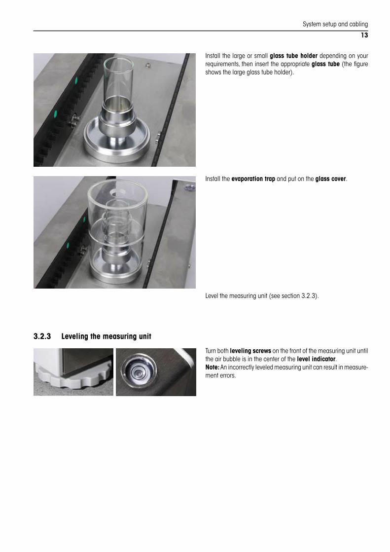
Installthelargeorsmallglass tube holderdependingonyourrequirements,theninserttheappropriateglass tube(thefigureshowsthelargeglasstubeholder).
Installtheevaporation trapandputontheglass cover.
Levelthemeasuringunit(seesection3.2.3).
3.2.3 Leveling the measuring unit
Turnbothleveling screwsonthefrontofthemeasuringunituntiltheairbubbleisinthecenterofthelevel indicator.Note:Anincorrectlyleveledmeasuringunitcanresultinmeasurementerrors.

Systemsetupandcabling
14
3.3 System cablingPlacetheevaluationunitnexttothemeasuringunitandthenplacethemotorcontrolunitontheevaluationunit.Thecomponentsarenowreadytobecabled.Note: For systems that include several MCP, only cable the associated components. In this case, please note the serial numbers on the evaluation unit and the measuring unit. They must be identical.
Cablethecomponentsasfollows:
A Connecttheevaluationunittothemeasuringunit.Todothis,usethe60 cmbalancecablewiththe25-pinconnectors(m/m).
B Connecttheevaluationunittothemotorcontrolunit.Todothis,usethe30cmCANcable(m/m).
C Connect themotorcontrolunit to themeasuringunit.Todothis,usethe60cmcontrolcablewiththe15-pinconnectors(m/m).
D Firstconnectthemotorcontrolunittothepowersupply.Todothis,useonlyoneofthetwoACadapterssupplied(primary:100- 240 VAC,50/60Hz,0.8A;secondary:12VDC,2.25A).Note:Ifthemotorcontrolunitisconnectedtothepowersupplyaftertheevaluationunit,problem-freeoperationofthesystemisnotguaranteed.
E Connecttheevaluationunittothepowersupply(themotorcontrolunitmustalreadybeconnectedtothepowersupply,seeabove).Todothis,useonlytheACadaptersupplied(primary:230VAC,50/60Hz,90mA;secondary:12VAC,1.25A).
F ConnectionofthemotorcontrolunittothePCbymeansofthesuppliedUSB/serialconverter.ThetypeofconnectiontothePCvariesdependingontheMCPsystemtypeandthescopeofdelivery.Forthemoment,werecommendthatyoudonotyetconnecttheMCPtothePCbutfirstfamiliarizeyourselfwiththeoperationoftheMCPinthenextsection.TheconnectiontothePCandthecorrespondingconfigurationaredescribedinsection9.
A
BC
F
E
D
Startupandmenusettings
15
4 Startup and menu settingsThissectionprovidesinformationaboutstartinguptheMCPandthemenusystem,whichcanbeusedtoadaptyourMCPtotherelevantoperatingconditions.ItisassumedthatallthecomponentsoftheMCPhavebeencabledcorrectly(section3).
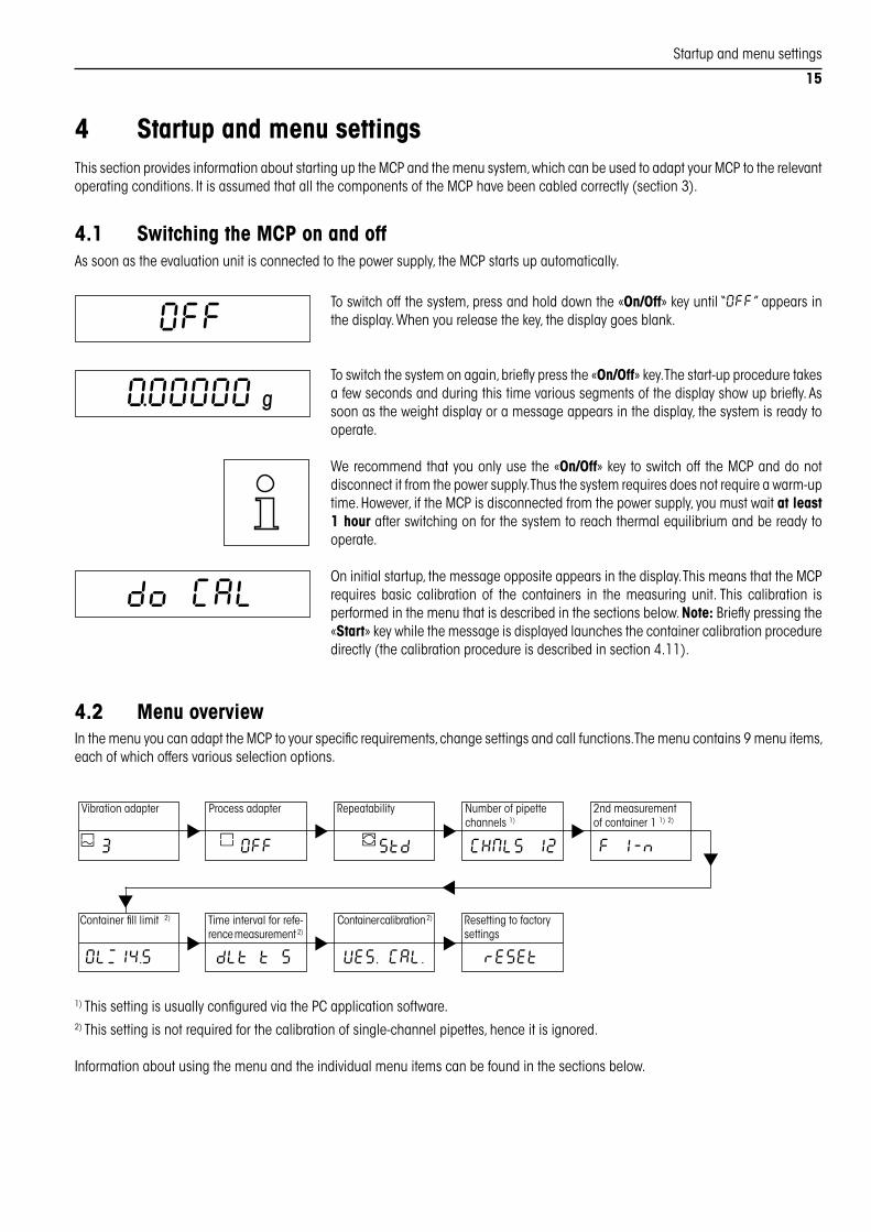
4.1 Switching the MCP on and offAssoonastheevaluationunitisconnectedtothepowersupply,theMCPstartsupautomatically.
Toswitchoffthesystem,pressandholddownthe«On/Off»keyuntil“OFF”appearsinthedisplay.Whenyoureleasethekey,thedisplaygoesblank.
Toswitchthesystemonagain,brieflypressthe«On/Off»key.Thestart-upproceduretakesafewsecondsandduringthistimevarioussegmentsofthedisplayshowupbriefly.Assoonastheweightdisplayoramessageappearsinthedisplay,thesystemisreadytooperate.
Werecommendthatyouonlyusethe«On/Off»keytoswitchoff theMCPanddonotdisconnectitfromthepowersupply.Thusthesystemrequiresdoesnotrequireawarm-uptime.However,iftheMCPisdisconnectedfromthepowersupply,youmustwaitat least 1 hourafterswitchingonforthesystemtoreachthermalequilibriumandbereadytooperate.
Oninitialstartup,themessageoppositeappearsinthedisplay.ThismeansthattheMCPrequires basic calibration of the containers in the measuring unit.This calibration isperformedinthemenuthatisdescribedinthesectionsbelow.Note:Brieflypressingthe«Start»keywhilethemessageisdisplayedlaunchesthecontainercalibrationproceduredirectly(thecalibrationprocedureisdescribedinsection4.11).
4.2 Menu overviewInthemenuyoucanadapttheMCPtoyourspecificrequirements,changesettingsandcallfunctions.Themenucontains9menuitems,eachofwhichoffersvariousselectionoptions.
Vibrationadapter Processadapter Repeatability Numberofpipettechannels1)
2ndmeasurementofcontainer11)2)
Containerfilllimit2) Timeintervalforrefe-rencemeasurement2)
Containercalibration2) Resettingtofactorysettings
CHNLS 12 F l - n
OLë14.5 dLt t 5 VES. CAL. rESEt
3 OFF Std
OFF
=O0000e
do CAL
1)ThissettingisusuallyconfiguredviathePCapplicationsoftware.2)Thissettingisnotrequiredforthecalibrationofsingle-channelpipettes,henceitisignored.
Informationaboutusingthemenuandtheindividualmenuitemscanbefoundinthesectionsbelow.

Startupandmenusettings
16
4.3 Using the menu
Calling the menu
Pressandholddownthe«Menu»keyuntil“D\ENU”appearsinthedisplay.Whenyoureleasethekey,thefirstmenuitemappears(Vibrationadapter).
Selecting the menu items
Brieflypressthe«j»keyinthemenu.Thenextmenuitemappearseachtimethekeyispressed.Afterthelastmenuitem(Resettofactorysettings),thefirstmenuitemisshownagain(Vibrationadapter).
Changing the setting in the selected menu item
Brieflypressthe«f»key.Thenextavailablesettingappearseachtimethekeyispressed.Afterthelastsetting,thefirstsettingisshownagain.Onceyouhaveselectedthedesiredsetting,brieflypressthe«j»keytoswitchtothenextmenuitem(seeabove).
Storing the settings and exiting the menu
Onceyouhavemadeallthedesiredsettings,pressandholddownthe«Menu»keyuntiltheMCPreturnstothenormaloperatingmode.Beforetheweightdisplayappears,theoptiontostorethesettingsisbrieflyconfirmed(“StorEd”).
Exiting the menu without storing the settings
Youcanexitthemenuatanytimebybrieflypressingthe«C»key.Anychangesyouhavemadeinthemenuwillnotbestored.
Note: Ifyoudonotpressanykeysforsometimeinthemenu,theMCPautomaticallyreturnstothenormaloperatingmodewithoutstoringanychanges.
D\ENU
OFF
3
3
CHNLS 4
CHNLS 5
rESEt
StorEd
=O0000e

Startupandmenusettings
17
4.4 Setting the vibration adapterInthefirstmenuitem(Vibrationadapter),theMCPcanbeadaptedtotheambientconditionsatthepointofinstallation(vibrations,drafts,etc.).
TheMCPispresetforoperationinunstableenvironmentsexworks(setting“3”,symbol-izedbythelargewave).
Ifyouareworkinginastableorverystableenvironment,youcanselectoneofthetwoothersettingsandthusincreasetheoperatingspeedoftheMCP:
Setting“1”(smallwave): Forextremelystableenvironments.
Setting“2”(mediumwave): Forstableenvironments.
3
OFF
Std
4.5 Setting the process adapterTheprocessadaptercanbeusedtoadaptabalancetodifferenttypesofweighing.
AsnormalweighingtasksarenotusuallyperformedbytheMCP,theprocessadapterisswitchedoff(setting“OFF”).We recommend that you do not change this setting as this can adversely affect the measuring performance.
4.6 Selecting repeatabilityThecirculariconforthestabilitydetectorislocatedinthebottomleftcornerofthedisplay.Assoonasthemeasurementresultiswithinthespecifiedlimitvaluesoveracertaintimeinterval,themeasurementresultisconsideredstableandtheiconforthestabilitydetectorfades.Therepeatability(“Repro-Set”)settingisusedtodeterminethetimeintervaloverwhichtheresultmustbewithinthelimitvaluesinorderforittobeconsideredstable.Thebettertherepeatability,thelongerthemeasurementprocesslasts.
TheMCPispresetforstandardrepeatabilityexworks(“Std”),i.e.themeasurementvalueisreleasedasstableveryquickly.Werecommendthatyoudonotchangethissettingsoasnottoprolongthemeasurementprocessunnecessarily.
Inadditiontothefactorysettings,4othersettingsareavailable:
“Good”: Quickreleaseofthemeasurementvalue.
“bEttEr”: Slowreleaseofthemeasurementvalue.
“bESt”: Oncestabilityhasbeenachieved,themeasurementvalueisonlyreleasedifithasnotchangedforafewseconds.
“OFF”: Thefunctionisswitchedoff,eachmeasurementvalueisconsideredstableandreleasedimmediately.
4.7 Selecting the number of pipette channelsThismenuitemisusedtodefinethenumberofchannelsforthepipettetobetested.Thisisusually1,8or12channels.TheMCPispresetfor12-channelpipettesexworks,butanynumberofchannelsbetween1and12canbeselected.
Important:Ifyouselect“1”inthismenuitem,youmustpreparethemeasuringunitforthecalibrationofsingle-channelpipettesasdescribedinsection3.2.2.
CHNLS 12

Startupandmenusettings
18
4.8 Activating/deactivating the second measurement of container 1TheMCPhasafunctionforasecondmeasurementofcontainer1,whichcanbeactivatedordeactivatedinthismenuitem.Note: This menu item applies to the calibration of multichannel pipettes only.
Second measurement deactivated (factory setting):Thereisnosecondmeasurementofthefirstcontainer(theplaceholder_isinsertedinthedatarecordinsteadoftheweightvalueofthesecondmeasurement,seesection9.3).
Second measurement activated:Oncepipettingiscomplete,theliquidinthefirstcon-tainerisweighedagain(secondmeasurement).Basedonthedifferenceinweightandthetimethathaselapsedbetweenthetwomeasurementstheevaporationratemaybecalculated.Theweightvalueofthesecondmeasurementisaddedtothedatarecordforthecurrentmeasuringcycle(seesection9.3).Important:Thevaluesrecordedfortheindividualpipettechannelsarenotchanged,onlyadditionalinformation(weightvalueofthesecondmeasurement)isavailable,whichcanbeevaluatedifnecessary.
F 1 - n .1
F 1 - n
4.9 Defining the fill limit of the containersThismenuitemcanbeusedtodefinethefilllimitforthe12containersinthemeasuringunit.Assoonasthislimitisreached,the“ED\PtY”levelwarningappearsinthedisplay,whichpromptsyoutoemptythecontainers.Note: This menu item applies to the calibration of multichannel pipettes only.
Thefilllimitissetto14.5 gexworks.Eachtimethe«f»keyispressed,thevaluechangesby0.1 g(settingrange:10.0...16.0 g).Topreventcontainersfromoverflowing,youshouldsetthelimitsothatthereisasafetymargin,whichcorrespondstothelargestvolumetobepipetted(filllimit=16.0 gminusthelargestvolumetobepipetted).
OLë 14.5
4.10 Defining the time interval for reference measurementFollowingeachmeasuringcycle,theMCPusestherecordedvaluesasareferenceforthenextpipettingoperation(thisprocesscorre-spondstotaringonastandardbalance).Thelongerthetimebetweentwomeasuringcycles,thegreaterthedangerthatthereferencevalueswillnolongerbevalidduetoevaporationandthesubsequentmeasurementwillthereforebeinaccurate.Thismenuitemcanbeusedtodefinethetimepermittedbetweentwomeasuringcycles.Ifthistimelimitisexceeded,the“do rEF”messageappearsinthedisplay,whichpromptsyoutodeterminethereferenceagain(bybrieflypressingthe«Start»key).Note: This menu item applies to the calibration of multichannel pipettes only.
Thetimeintervalforreferencemeasurementissetto5(minutes)exworks.Eachtimethe«f»keyispressed,thevaluechangesby1minute(settingrange:1...10minutes).dLt t 5

Startupandmenusettings
19
4.11 Calibrating the containersOninitialstartup,theMCPpromptsyoutocalibratethe12containersinthemeasuringunitwiththe“do CAL”message.Thefilllimitsofthecontainersarebasedontheemptyweightsofthecontainers(section4.9).Whenthe“do CAL”messageisshowninthedisplay,youmaylaunchthecalibrationprocedurebypressingthe«Start»keybriefly.Themessage“CAL.StArt”confirmsthatthecalibrationprocedurehasstarted(seebelow).However,youmayinitatecontainercalibrationatanytimeviathemenu,asdescribedbelow(thisisrecommendedaftereverychangeoflocation).Note: This menu item applies to the calibration of multichannel pipettes only.
Note: Only perform this calibration operation if you are sure that the containers are empty and dry, otherwise the “ED\PtY” level warning appears too late during pipetting and the containers can overflow.
Ifyouwanttocalibratethecontainers,pressandholddownthe«j»keyuntil:
Themessageoppositeappearsinthedisplay,whichconfirmsthestartofthecalibrationoperation(thecalibrationoperationcanbecanceledatanytimeusingthe«C»key).Therackofthemeasuringunitthenmovesbackwardsstep-by-stepandoneofthecontain-ersisweighedwitheachstep.Youcanfollowtheprogressofmeasurementprocessinthedisplay.Oncethelastcontainerhasbeenweighed,therackmovesbacktotheinitialposition.
Followingsuccessfulcompletionofcalibration,theconfirmationoppositeappearsbrieflyandtheMCPexitsthemenuandreturnstothenormaloperatingmode.
Note: If the“Abort” message appears instead of the confirmation, the calibrationoperationcouldnotbeperformedproperly(e.g.duetoadraftorvibrations)andmustberestarted.
VES. CAL.
CAL.StArt
CAL donE
4.12 Resetting to factory settingsThismenuitemcanbeusedtoresetallmenusettingstothefactorysettings.
Note: All the individual menu settings are lost in the event of a reset. The calibra-tion values of the containers are also deleted and the calibration operation must be repeated with empty containers (section 4.11). We therefore recommend that you only execute a reset if you are sure that you really want to carry out the required calibration with empty containers.
Ifyouwanttoresettothefactorysettings,pressandholddownthe«j»keyuntil:
Theconfirmationoppositeappearsinthedisplay.TheMCPthenexitsthemenuandreturnstothenormaloperatingmode.
Note:Followingreset,the“do CAL”messageappearsinthenormaloperatingmode,whichpromptsyoutocalibratethecontainers(section4.11).
rESEt
r donE

WorkingwiththeMCP
20
5 Working with the MCPThissectionprovidesinformationabouthowtoworkwiththeMCP.ItonlyexplainshowtoworkontheMCP,informationaboutevaluat-ingthedataonthePCandaboutusingtheoptionalPCapplicationsoftwarecanbefoundinthedocumentationsuppliedwiththesoftware.
5.1 Calibrating the weighing cellInordertoensuretheaccuracyofthemeasurementresults,theweighingcellbuiltintointhemeasuringunitmustbecalibratedonthefollowingoccasions:
– Oninitialstartup(allowatleast60minuteswarm-uptimebeforecarryingoutthecalibration)
– Aftereverychangeoflocation
– Whenthesmall“Cal”symbolappearsintheupperpartofthedisplay(theweighingcellispermanentlymonitoredandthe“Cal”symbolappearsautomaticallyassoonasthecellrequiresre-calibration).The“Cal”symboldisappearsuponsuccessfulcompletionofthecalibration.
Regardlessoftheabovecalibrationintervalswestronglyrecommendtocalibratetheweighingcellatleastonceaday.Thecalibrationisperformedwithbuilt-inweights.
SwitchtheMCPonwiththe«On/Off»key.Note:IftheMCPwasdisconnectedfromthepowersupply,waitatleastanhourafterswitchingonforthesystemtoreachthermalequilibrium.
Pressandholddownthe«Cal»keyuntilthedisplayoppositeappears.Whenyoureleasethekey,calibrationbegins.
Youcanfollowtheprogressofthecalibrationoperationinthedisplay:First,shorthorizontalbarsaredisplayedwhilethezeropointisbeingdetermined.Themaximumloadingrams(“100.00000 ”)thenappearsinthedisplay,followedbythezeroload(“0.00000”).Note:Thecalibrationoperationcanbecanceledatanytimebypressingthe«C»key.
SuccessfulcompletionofcalibrationisbrieflyconfirmedwiththemessageoppositeandtheMCPthenreturnstothenormaloperatingmode.
Note:IftheMCPabortsthecalibrationoperationwiththe“Abort”message;unstableambientconditions(draft,vibrations,etc.)areusuallythecause.Clearthemessagebybrieflypressingthe«C»key,makesuretheambientconditionsarestableandrestartthecalibrationoperation.
CAL donE
CAL int
5.2 Preparing the work station
Placethewater reservoirsuppliedonyourworkstationandfill itwithdistilledwater.Waitatleast1hourbeforestartingpipetting.Thisensuresthatthewaterisatambienttemperature.
Note:IfyoudonotworkwiththeMCPforanextendedperiodoftime(e.g.overnight),youshouldplacethecoversuppliedoverthereservoirinordertopreventthewaterbecomingcontaminated.
Thewaterreservoirshouldbereplacedfromtimetotime,asdespitetheuseofdistilledwater,aslimydepositcanformovertimeduetoimpuritiesintheair.Replacementreser-voirscanbeorderedfromMETTLERTOLEDO(section8).
WorkingwiththeMCP
21
5.3 Testing multichannel pipettes
Thedescriptionsinthissectionassumethatthefollowingworkhasalreadybeencarriedout:
– Correctcablingofallsystemcomponents(section3.3)
– Assemblyofthemeasuringunitfortheverificationofmultichannelpipettes(section3.2.1)
– Settingofthenumberofpipettechannels(section4.7)
– Calibrationofthecontainers(section4.11)
– Othermenusettings,ifrequired(section4)
– Calibrationoftheweighingcell(section5.1).
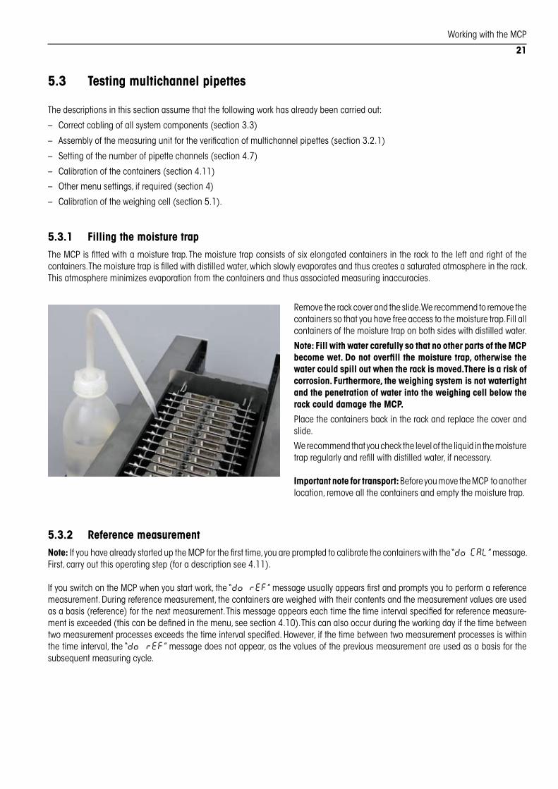
5.3.1 Filling the moisture trapTheMCPisfittedwithamoisturetrap.Themoisturetrapconsistsofsixelongatedcontainersintheracktotheleftandrightofthecontainers.Themoisturetrapisfilledwithdistilledwater,whichslowlyevaporatesandthuscreatesasaturatedatmosphereintherack.Thisatmosphereminimizesevaporationfromthecontainersandthusassociatedmeasuringinaccuracies.
Removetherackcoverandtheslide.Werecommendtoremovethecontainerssothatyouhavefreeaccesstothemoisturetrap.Fillallcontainersofthemoisturetraponbothsideswithdistilledwater.
Note:Fill with water carefully so that no other parts of the MCP become wet. Do not overfill the moisture trap, otherwise the water could spill out when the rack is moved. There is a risk of corrosion. Furthermore, the weighing system is not watertight and the penetration of water into the weighing cell below the rack could damage the MCP.
Placethecontainersbackintherackandreplacethecoverandslide.
Werecommendthatyouchecktheleveloftheliquidinthemoisturetrapregularlyandrefillwithdistilledwater,ifnecessary.
Important note for transport:BeforeyoumovetheMCPtoanotherlocation,removeallthecontainersandemptythemoisturetrap.
5.3.2 Reference measurementNote:IfyouhavealreadystarteduptheMCPforthefirsttime,youarepromptedtocalibratethecontainerswiththe“do CAL”message.First,carryoutthisoperatingstep(foradescriptionsee4.11).
IfyouswitchontheMCPwhenyoustartwork,the“do rEF”messageusuallyappearsfirstandpromptsyoutoperformareferencemeasurement.Duringreferencemeasurement,thecontainersareweighedwiththeircontentsandthemeasurementvaluesareusedasabasis(reference)forthenextmeasurement.Thismessageappearseachtimethetimeintervalspecifiedforreferencemeasure-mentisexceeded(thiscanbedefinedinthemenu,seesection4.10).Thiscanalsooccurduringtheworkingdayifthetimebetweentwomeasurementprocessesexceedsthetimeintervalspecified.However,ifthetimebetweentwomeasurementprocessesiswithinthetimeinterval,the“do rEF”messagedoesnotappear,asthevaluesofthepreviousmeasurementareusedasabasisforthesubsequentmeasuringcycle.
WorkingwiththeMCP
22
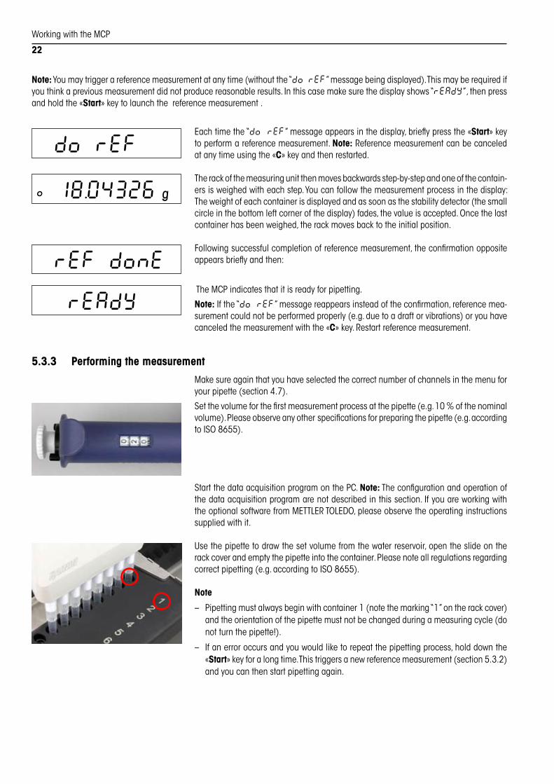
Eachtimethe“do rEF”messageappearsinthedisplay,brieflypressthe«Start»keytoperformareferencemeasurement.Note:Referencemeasurementcanbecanceledatanytimeusingthe«C»keyandthenrestarted.
Therackofthemeasuringunitthenmovesbackwardsstep-by-stepandoneofthecontain-ersisweighedwitheachstep.Youcanfollowthemeasurementprocessinthedisplay:Theweightofeachcontainerisdisplayedandassoonasthestabilitydetector(thesmallcircleinthebottomleftcornerofthedisplay)fades,thevalueisaccepted.Oncethelastcontainerhasbeenweighed,therackmovesbacktotheinitialposition.
Followingsuccessfulcompletionofreferencemeasurement,theconfirmationoppositeappearsbrieflyandthen:
TheMCPindicatesthatitisreadyforpipetting.
Note:Ifthe“do rEF”messagereappearsinsteadoftheconfirmation,referencemea-surementcouldnotbeperformedproperly(e.g.duetoadraftorvibrations)oryouhavecanceledthemeasurementwiththe«C»key.Restartreferencemeasurement.
do rEF
rEF donE
rEAdY
5.3.3 Performing the measurement
Makesureagainthatyouhaveselectedthecorrectnumberofchannelsinthemenuforyourpipette(section4.7).
Setthevolumeforthefirstmeasurementprocessatthepipette(e.g.10%ofthenominalvolume).Pleaseobserveanyotherspecificationsforpreparingthepipette(e.g.accordingtoISO8655).
StartthedataacquisitionprogramonthePC.Note:Theconfigurationandoperationofthedataacquisitionprogramarenotdescribedinthissection.IfyouareworkingwiththeoptionalsoftwarefromMETTLERTOLEDO,pleaseobservetheoperatinginstructionssuppliedwithit.
Usethepipettetodrawthesetvolumefromthewaterreservoir,opentheslideontherackcoverandemptythepipetteintothecontainer.Pleasenoteallregulationsregardingcorrectpipetting(e.g.accordingtoISO8655).
Note
– Pipettingmustalwaysbeginwithcontainer1(notethemarking“1”ontherackcover)andtheorientationofthepipettemustnotbechangedduringameasuringcycle(donotturnthepipette!).
– Ifanerroroccursandyouwouldliketorepeatthepipettingprocess,holddownthe«Start»keyforalongtime.Thistriggersanewreferencemeasurement(section5.3.2)andyoucanthenstartpipettingagain.
Ñ 18.04326e
Note:Youmaytriggerareferencemeasurementatanytime(withoutthe“do rEF”messagebeingdisplayed).Thismayberequiredifyouthinkapreviousmeasurementdidnotproducereasonableresults.Inthiscasemakesurethedisplayshows“rEAdY”,thenpressandholdthe«Start»keytolaunchthereferencemeasurement.

WorkingwiththeMCP
23
– Youmayspeedupthemeasurementbyreducingtheresolutionofthemeasuredvaluesto4decimalplaces(insteadof5).Brieflypressthe«1/10»keytotoggletheresolutionbetween4and5decimalplaces.However,thelowresolutionisrecommendedonlyforlarge-volumepipetteswherearesolutionof4decimalplacesissufficient.Note:TheselectedresolutionisnotlimitedtothedisplayofmeasuredvaluesbutalsoaffectsthedatarecordstransferredviatheMCPinterface(section9.3).
Closetheslideandbrieflypressthe«Start»keytotriggerthemeasurementprocess.Note:Themeasurementprocesscanbecanceledatanytimeusingthe«C»key,however,theMCPthenrequiresanewreferencemeasurement.
The rack of the measuring unit then moves backwards step-by-step and one of thecontainersisweighedwitheachstep.Oncethelastcontainerhasbeenmeasured,therackreturnstotheinitialposition.Note:Ifyouhaveactivatedthesecondmeasurementofcontainer1inthemenu(section4.8),thefirstcontainerisweighedasecondtimetocompletethemeasurement.
Successfulcompletionofthemeasurementisconfirmedbrieflywiththemessageopposite.The“rEAdY”messagethenappearsandtheMCPisreadyforthenextmeasurement.donE
5.3.4 Emptying the containers
ED\PtYAssoonasoneofthecontainershasreachedthefilllimitspecifiedinthemenu(section4.9),therequestoppositetoemptythecontainersappears.
ConnectthesuctionpumpsuppliedtothepowersupplyviatherelevantACadapter.Note:Anoptional4-channelsuctionpumpisavailabletoincreaseefficiencywhenemptyingthecontainers,seesection8.8.
Connectthesuctiontube(withtheprobe)totheinput(“IN”)onthepump.Connectthesecondtubetotheoutputonthepump(“OUT”)andplacethefreeendinasuitablecollector.
Carefullyinsertthesuctionprobeinthefirstcontainer.Pressthe“ON”switchonthepumpandemptythecontainer.Thisonlytakesafewseconds.Repeatthisprocessuntilallthecontainershavebeenemptied.
Note:Do not allow the pump to run dry for too long as it may become damaged. When handling the probe, make sure that no other parts of the MCP become wet. There is a risk of corrosion. Furthermore, the weighing system is not watertight. The penetration of water into the weighing cell below the rack can damage the MCP.
Thenext timethe«Start»key ispressed, theMCPrechecksthe liquid level. If there isstillmorethan2 mlofliquidinoneofthecontainers,the“ED\PtY”messageappearsagain.

WorkingwiththeMCP
24
5.4 Testing single-channel pipettes
Thedescriptionsinthissectionassumethatthefollowingworkhasalreadybeencarriedout:
– Correctcablingofallsystemcomponents(section3.3)
– Assemblyofthemeasuringunitfortheverificationofsingle-channelpipettes(section3.2.2)
– Settingthenumberofpipettechannelsto“1”(section4.7)
– Calibrationoftheweighingcell(section5.1).
5.4.1 Filling the moisture trap
Removetheglasscoverfromtheevaporationtrap.
Filltheevaporationtrapwithdistilledwater.
Note:Fill with water carefully so that no other parts of the MCP become wet. There is a risk of corrosion. Furthermore, the weighing system is not watertight and the penetration of water into the weighing cell below the rack could damage the MCP.
Putontheglasscoveragain.
Werecommendthatyouchecktheleveloftheliquidinthemoisturetrapregularlyandrefillwithdistilledwater,ifnecessary.
5.4.2 Performing the measurement
Setthevolumeforthefirstmeasurementprocessatthepipette(e.g.10%ofthenominalvolume).Pleaseobserveanyotherspecifi-cationsforpreparingthepipette(e.g.accordingtoISO8655).
StartthedataacquisitionprogramonthePC.Note: Theconfigurationandoperationofthedataacquisitionprogramarenotdescribedinthissection.IfyouareworkingwiththeoptionalsoftwarefromMETTLERTOLEDO,pleaseobservetheoperatinginstructionssup-pliedwithit.

WorkingwiththeMCP
25
Drawthesetvolumefromthewaterreservoir,thenemptythepipetteintotheglasstube.Pleasenoteallregulationsregardingcorrectpipetting(e.g.accordingtoISO8655).
Themeasuredweightvalueappearsinthedisplay.Pressthe«Start»keytotransferthevalueviatheinterface.Threeconcentriccirclesaredisplayedatthetopedgeofthedisplaywhiledatatransferisinprogress.Assoonasthethreecirclesdisappear,datatransferiscompleteandtheMCPisreadyforthenextmeasurement.
Note
– Pressingthe«Start»keytransmitsthedisplayedvalueviatheinterface.Thisvalueiscumulative,i.e.theMCPcontinuouslysumsupallmeasurements.Incaseyourparticulardataacquisitionprogram requires theweight valueofevery singlemeasure-mentyouwillhavetoresettheMCPdisplaytozero(withthe«k»key)beforestartingthenextmeasurement.
– Youmayspeedupthemeasurementbyreducingtheresolutionofthemeasuredvaluesto4decimalplaces(insteadof5).Brieflypressthe«1/10»keytotoggletheresolutionbetween4and5decimalplaces.However,thelowresolutionisrecommendedonlyforlarge-volumepipetteswherearesolutionof4decimalplacesissufficient.Note:Theselectedresolutionisnotlimitedto the display of measured values but also affects the datarecordstransferredviatheMCPinterface(section9.3).
0.02016e

Statusanderrormessages
26
6 Status and error messagesTheMCPdisplaysmessagestoinformyouaboutthecurrentinstrumentstatus,actionstobecarriedoutandanyerrors.
Message Meaning Action required/note
rEAdYThe MCP is ready for the next measure-ment
None
donEThemeasurementwassuccessfullycom-pleted.
Themessagedisappearsaftera fewseconds.
do rEFReferencemeasurementrequired Performreferencemeasurement(sec-
tion5.3.2).Ifreferencemeasurementdoesnotstartandthemessagereap-pears, check the hardware (correctinstallation of the weighing yoke,containers,moisture in theweighingsystem,etc.).
ED\PtYContainerfilllimithasbeenreached. Emptycontainers(section5.3.4).
do CALBasiccalibrationofthecontainersrequired.
Themessageonlyappearsoninitialstartupandwhenthemenusettingshavebeenresettothefactorysettings.Perform basic calibration (section4.11).
no FuncYouhavepressedakey,whichdoesnothaveafunctioninthiscontext.
Pressthecorrectkey.
AbortA measurement or calibration operation(calibrationof the containersor internalcalibrationoftheweighingcell)couldnotbecompletedproperly.
Makesuretheambientconditionsarestableandrestartthemeasurementorcalibrationoperation(section4.11and5.1).Ifnecessary,changethelocationoftheMCP.
wssssxOverload Check that the weighing yoke is in-
stalledcorrectly(sec.3.2.1).Iftherackisintheinitialposition,noweightmaybeplacedonthecantileverarm.
y____zUnderload Check that the weighing yoke is in-
stalledcorrectly(section3.2.1).

Statusanderrormessages
27
Message Meaning Action required/note
The MCP is searching for the zero point(waitingtoreachstability).
None
rEF Err.Youhaveattemptedtostartameasurementeven though a reference measurementmustfirstbeperformed.Thismessageonlyappears if youcontrol theMCPviaSICScommandsfromaPC(section9).
First,performareferencemeasurement(viatheMCPkeypadorwiththerelevantSICScommand)andthenrestartthemeasuringcycle.
Cal Theweighingcellrequirescalibration. Calibrate the weighing cell as soonas possible (section 5.1).The“Cal”symbol disappears upon successfulcompletionofthecalibration.

Cleaningandservice
28
7 Cleaning and serviceCleanallthecomponentsoftheMCPeveryonceinawhileusingaslightlydampenedcloth.Ifnecessary,useacommerciallyavailable,mildcleaningagent.Tocleanthemeasuringunitthoroughly,proceedasfollows:
DisconnecttheACadapterofthemeasuringunitfromthepowersupply.
Unplugalltheconnectorsfromthebackofthemeasuringunit.
Removetheslideandtherackcover.
Carefullyliftall12containersfromtherack.Caution: The glass tubes are fragile!
Carefullylifttherackverticallyfromtheracksupport.
Removetheweighingyoke.
Lifttheracksupportoutofthemeasuringunit.
Cleanallthepartsusingaslightlydampenedcloth.Note:Makesurethatnomoisturepenetratestheweighingcell.Ifnecessary,covertheweighingyokeopeningwithadhesivetape.
Forcleaningpurposestheglass tubes of the containersmayberemovedasfollows:Slidethesuppliedrubberconeovertheglasstubeandwithdrawthetubefromthecontainer.Aftercleaning,drytheoutsideoftheglasstubeandthetubeguideofthecontainercovercarefully(duetocapillaryactionincreasedevaporationmayoccurifthesepartsarewet)!Relocatetheglasstube.Note:Theglasstubesshouldbefirmlyseatedthustheycannotberemovedbyhand.Incaseaglasstubeisnotfirmlyseated,removeitandthenslightlysqueezethecontaineronbothsides.Relocatetheglasstubeandcheckforproperseatingagain.Aftercleaning,replaceallthepartsinthemeasuringunit(section3.2.1).Thencheckwhetherthemeasuringunitisstillleveledcor-rectly(section3.2.3).Reconnectthemeasuringunittotheevalu-ationunitandthemotorcontrolunit.ConnecttheACadaptertothemeasuringunitandconnectthemeasuringunittothepowersupply.
Important notes
– Neverusecleaningagents,whichcontainsolventsorabrasiveingredients.Suchagentscancausescratchedsurfaces,especiallyinthecaseofthecoverglassofthedisplayontheevaluationunit.
– MakesurethatnoliquidpenetratestheindividualcomponentsoftheMCPorcomesintocontactwiththeconnectionsonthebackofthehousing.
– NeveropenthehousingofMCPcomponents,theydonotcontainanypartsthatcanbecleaned,repairedorreplacedbytheuser.
AskyourMETTLERTOLEDOdealerabouttheserviceoptionsavailable–regularservicingbyanauthorizedservicetechnicianensuresmeasuringaccuracyforyearsandprolongstheservicelifeofyourMCP.

Technicaldataandaccessories
29
8 Technical data and accessoriesThissectioncontainsthetechnicaldataoftheMCPandinformationaboutoptionalaccessoriesthatarecurrentlyavailable.Informationaboutstandardequipmentcanbefoundinsection2.
8.1 MCP105 data
Number of channels: 1...12
Volume of the containers: 16 ml(levelwarningconfiguredinthemenu)
Measuring time for 8/12 channels: 70 s/110 s(incl.repeatedmeasurementofthefirstcontainer)
Moisture trap: Built-in
Evaporation rate calculation : Byremeasuringthefirstcontainer,canbeactivatedviathemenu
Minimum measuring volume: 10 µl(formeasurementsaccordingtoISO8655)
Weighing module data (built into the measuring unit):
Readability: 0.01 mg
Max. load: 101 g
Measurement uncertainty: 0.02 mg
Stabilization time: approx.5 sec
ThisdataisonlyvalidiftheMCPisoperatedwithinthespecifiedambientconditions(section8.2).
8.2 Ambient conditionsProblem-freeoperationoftheMCPandcompliancewiththeweighingmoduletechnicalspecifications(section8.1)areonlyensuredunderthefollowingambientconditions:
Installation location: Closed,dryrooms.Operationinhazardousenvironmentsisnotpermitted.
Height above sea level: Upto4000 m
Ambient temperature: 5–40 °C(41–104 °F)
Relative atmospheric humidity: Max.80 %at31 °C,lineardecreaseofupto50 %at40 °C,non-condensing
Warm-up time: 60minutes,minimumfollowingconnectiontothepowersupply(iftheevaluationunitandmotorcontrolunitarepermanentlyconnected to thepowersupply, theMCPrequiresnowarm-uptimeafterswitchingonwiththe«On/Off»keyandisim-mediatelyreadytooperate).
8.3 Protection and standards
Installation category: Class2
Pollution degree: 2
Protection: Protectedagainstdustandwater
Safety and EMC: Seedeclarationofconformity(separatebrochure11780294)

Technicaldataandaccessories
30
8.4 Power supplyOnly the AC adapters suppliedshouldbeusedtosupplypowertotheevaluationunit,motorcontrolunitandsuctionpumpwithcountry-specificpowercablesand3-pinconnectors.Themeasuringunitdoesnotrequireconnectiontothemains,itissuppliedbytheevaluationunitandthemotorcontrolunit.
AC adapter for the evaluation unit (suppliedwithwallmountingplate)
OneofthefollowingACadaptersissupplieddependingonthedestinationcountry:
Primary: 115 VAC(-20/+15%),50/60Hz,195mA, secondary:12VAC,1.25A
Primary: 230 VAC(-20/+15%),50/60Hz,90mA, secondary:12VAC,1.25A
AC adapter for the motor control unit and suction pump
Primary: 100-240 VAC(-15/+10%),50/60Hz,0.8A
Secondary: 12 VDC(±5%),2.25Amax.(electronicprotectionagainstoverload)
8.5 RS232C interface dataThebuilt-inRS232CinterfaceinthemotorcontrolunitisusedastheMCPconnectiontoaPC(directorviaUSB/serialconverter).Theinterfacehasthefollowingspecifications:
Interface type: Voltage-controlledinterfaceaccordingtoEIARS-232C/DIN66020(CCITTV.24/V.28)
Max. cable length: 15 m
Signal level: Outputs: Inputs:
+5 V...+15 V(RL=3-7 kΩ) +3 V...25 V
-5 V...-15 V(RL=3-7 kΩ) -3 V...25 V
Connection: 9-pinD-SUB,female
Operating mode: Fullduplex
Transmission mode: Bit-serial,asynchronous
Transmission code: ASCII
Baud rates: 600,1200,2400,4800,9600(factorysetting)1)
Bits/parity: 7bit/even,7bit/odd,7bit/none,8 bit/none(factorysetting)1)
Stop bits: 1 stop bit(factorysetting)2),2stopbits
Handshake: None,XON/XOFF(factorysetting),RTS/CTS1)
End of line: <CR><LF>2)
Pin assignment: Pin2:MCPtransmittingline(TxD)
Pin3:MCPreceivingline(RxD)
Pin4:Readytoreceive(hardwarehandshake)(DTR)
Pin5:Signalground(GND)
Pin6:Cleartosend(hardwarehandshake)(DSR)
1) FactorysettingcanbemodifiedbyMETTLERTOLEDOservicetechnicians2) Settingcannotbemodified
6
15
9
DataGND

Technicaldataandaccessories
31
8.6 Dimensions and weights
Evaluation unit and motor control unit
Weightofmotorcontrolunit: 0.6 kg
Weightofevaluationunit: 1.2 kg
Measuring unit
Weightofmeasuringunit: 6 kg
220
mm 91
mm
177 mm
296
mm
160 mm
88 mm
171 mm
164
mm

Technical data and accessories
32
8.7 MCPtechnicalspecificationsThe following table contains the times measured by METTLER TOLEDO for testing a pipette on systems consisting of 1 to 5 MCP. De-pending on the MCP model, the relevant environment and the work technique, the measuring times may in practice deviate from those provided.
To calculate the measuring times, the following two test methods were used that are based on the most commonly used test meth-ods:
– MethodA: 10measurements each at 10 %, 50 % and 100 % of the nominal volume of the pipette, this complies with the require-ments of ISO 8655.
– MethodB: 4measurements each at 10 %, 50 % and 100 % of the nominal volume of the pipette.
NumberofMCP–> 1*MCP 2*MCP 3*MCP 4*MCP 5*MCP
Method Channels
A 12 59 30 21 17 14
A 8 51 26 18 15 12
B 12 24 13.5 10 8 7.5
B 8 21 11.5 8.5 7 6.5
All measuring times are specified in minutes, based on measurements made with the MCP105 model.
Assumedhandlingtimerequiredtodeterminethemeasuringtimes
Multichannel pipettes: Per pipetting operation 10 seconds
Volume change: Per change 10 seconds
8.8 Accessories
Designation Articleno.
“Calibrysoftware” (Microsoft Windows®) with operating instructions, singleworkstationversion 11138419
“Calibrysoftware” (Microsoft Windows®) with operating instructions, singleworkstationversionLight 11138423
“Calibrysoftware” (Microsoft Windows®) with operating instructions, network-compatibleversion 11138420
CalibryUpdate 11123915
ProgramCasetteMCP 11138300
Calibrationkitforcontrolofinspection,measuringandtestequipment (calibration of the weighing module using external weights)
11138254
4-channelsuctionpump for emptying the containers 11138252
Single-channelkit100µl 11138008
Single-channelkit20ml 11138006
WorkingtableMCP5 (140 x 140 x 78 cm) 11138043
WorkingtableMCP2 (80 x 80 x 78 cm) 11138040

Technicaldataandaccessories
33
8.9 Spareparts
Designation Articleno.Waterreservoir(asareplacementforthewaterreservoirsupplied),setof5pcs 11600616Watercontainer(includingglasstube) 11138266Glasstubes(forthewatercontainers),setof5pcs 11138253Slideforrackcover 11138123Rackcover 11138121Rack 11138265Supportforevaluationunit 11138024Sparepartsforsingle-channelpipettes Glasscover
Evaporationtrap
Glasstubesmall15mmdiameter
Glasstubeholderfor15mmglasstube
Glasstubelarge24mmdiameter
Glasstubeholderfor24mmglasstube
Weighingpan
Centeringring
00210863
00210862
00210864
00210870
00210865
00210869
11138259
00210872CablesPoweradaptorformotorcontrolunitandsuctionpump
ACadaptorforevaluationunit
PowercablesfortheACadapters DK GB USA AUS SA Euro(grd) CH I
1“BalanceCable”(connectioncableforevaluationunit/measuringunit60cmlong,25-pin,m/m)
1“CANCable”(connectioncableforevaluationunit/motorcontrolunit30cmlong,m/m)
1“ControlCable”(connectioncableformotorcontrolunit/measuringunit60cmlong,15-pin,m/m)
1USB/serialconverter
USBHub
11107909
00224570
0008745200089405000886680008875100089728000879250008792000087457
00211535
00239259
11138403
11103691
11600611Single-channelsuctionpump 11138268Tubeforsuctionpump 11138132Largetransportcase 11138351Smalltransportcase 11138350

Appendix:MCPandhostcomputer
34
9 Appendix: MCP and host computerThissectionprovidesinformationaboutconnectingoneormoreMCPtoahostcomputer(PC),settingupanetworkwithseveralMCPandtheSICScommandsthataresupportedbytheMCP.
Caution: Do not place the PC keyboard on the same working surface as the MCP! Using the keyboard produces vibrations which may cause the MCPxxx to abort a running action (such as a reference mea-surement). The MCP then requires to perform the appropriate action again before further commands can be processed.
9.1 Connection to the host computerTheMCPsystemisusuallyconnectedtothehostcomputer(PC)viaaUSB(UniversalSerialBus)andallpartsrequiredforthisareincludedinthescopeofdelivery.Inprinciple,adirectconnectiontotheRS232Cinterface(s)onthecomputerisalsopossible.AnRS232CinterfacemustthereforebeavailableonthecomputerforeachMCP.Thevariousoptionsforconnecting via USBareexplainedbelow.
ThePCconnectionisdoneviathe9-pinRS232Cinterfaceconnectorlocatedonthebackpanelofthemotorcontrolunit.
System consisting of a single MCP, supplied with a USB/se-rial converter
Insert the 9-pin connector of the USB/serial converter into theRS232Cinterfaceofthemotorcontrolunit.
InserttheUSBcableoftheconverterinafreeUSBinterfaceonyourPC.
System consisting of several MCP, supplied with several USB serial converters and a USB hub
Insert the9-pinconnectorof theUSB/serialconverters into theRS232Cinterfaceofthemotorcontrolunits.
ConnecttheUSBcableofeachconvertertotheUSBhub.
ConnectthehubtoafreeUSBinterfaceonyourPC.
MCPMotorcontrolunit
PC
USB/serialconverter
USBcable
RS232C9-pUSB
MCPMotorcontrol
unit1
PC
USB
cabl
e
RS232C9-pUSB
USBHubUSBcable
USB/serialconverter
MCPMotorcontrol
unitnRS232C9-p
USB/serialconverter
USBcable

Appendix:MCPandhostcomputer
35
System consisting of several MCP, supplied with a USB hub with an integrated USB/serial converter
ConnectthefreeendoftheRScableofeachMCPmotorcontrolunitdirectlytoanRSconnectiononthehub.
ConnectthehubtoafreeUSBinterfaceonyourPC.
MCPMotorcontrol
unit1
PCUS
Bca
ble
RS232C9-pUSB
MCPMotorcontrol
unitn
USBhubwithintegratedUSB/serialconverter
RScable
RS232C9-p
RS23
2C9
-p
RScable
9.2 PC softwareThenetwork-compatibleandvalidatable“Calibry” softwareavailablefromMETTLERTOLEDOcanbeusedonthePCasanoption.Alternatively,theMCPcanbeintegratedintoindividual(existingorspeciallycreated)applications.Thissectionbrieflyexplainsthefunc-tionsofthesoftwareandprovidesanoverviewoftheinteractionbetweentheuser,MCPandsoftware.
9.2.1 PC software functionsInprinciple,thePCsoftwarecarriesoutthefollowingtasks:
– ConfiguringtheconnectedMCP
– Distinguishingbetweendataandcontrolcommands
– AssigningCOMportstoindividualmeasurementproceduresandcancelingtheassignmentfollowingcompletionofthemeasure-ment(thereservationofCOMportsisdescribedbelow)
– Startingreferencemeasurements(usingSICScommands,seesection9.3)
– Monitoringthenumberofpipettingoperationscompletedandstillinprogress
– Storingmeasurementdata
ThePCsoftwareisnotusedtocontrolthemeasurementprocedure,thisisexecutedbytheMCPalone(thePCsoftwarecanonlytriggerameasurement/referencemeasurementorcancelaprocessthatisinprogress).ThePCsoftwaredoesnotrequestanydata,thisistransferredindependentlybytheMCP.
Thediagramsinthesubsequentsectionsshowtheworkflowuponinitializationandconfigurationofthemeasuringsystem,therefer-encemeasurement,andthemeasurementofpipettes.Pleasenotethefollowing:
– ThediagramsshowjustoneMCP.IfasystemincludesseveralMCPxxx,thecommandsaresenttoeachunit.
– Spacesaredesignatedwith“_”,“<CRLF>”meansASCIIcharacters0x0D0x0A,<TAB>meansASCIIcharacter0x09.
– Allvaluesshowninthediagramsareexamples.

Appendix:MCPandhostcomputer
36
9.2.2 Initialization and configuration of the measuring systemThefollowingillustrationshowstheinteractionbetweentheuser,PCsoftwareandMCPwheninitializingandconfiguringthemeasuringsystem.
MCP Controller MCPxxxMCP Operator
1: start MCP controller
2: open serial port
3: request device type ( I2<CRLF>)
4: return device type
5: request software versions (I3<CRLF> )
6: return software versions
8: return serial number
7: request serial number (I4<CRLF>)
9: return status
10: configure measurement
11: configure (e.g. A107_12_0<CRLF>)
12: confirm (A107_A<CRLF>)
13: return status
14: start reference measurement
15: start reference measurement (A109<CRLF>)
19: reference measurement done (A109_A<CRLF>)
20: return status
18: do reference measurement
16: reference measurement started (A109_B<CRLF>)
17: return status
21: display status 'READY'
(e.g. I2_A_"MCP105_101.00090_g"<CRLF>)
(e.g. I3_A_"1.66_1.00_26080842"<CRLF>)
(e.g. I4_A_"1113153280"<CRLF>)

Appendix:MCPandhostcomputer
37
9.2.3 Measurement procedureThefollowingillustrationshowsthesequenceofameasurementprocess.
MCP Controller MCPxxxMCP Operator
1: dispense desired volume
21: display status 'READY'()
6: measure channel #1()
2: press 'START'
3: measurement started (A108_B<CRLF>)
7: return channel #1 weight (e.g. 0.00015<TAB>)( )
8: measure channel #2()
9: return channel #2 weight (e.g. 0.00014<TAB>)()
11: measure channel #8()
10: ...channels #3..#7...
12: return channel #8 weight (e.g. 0.00013<TAB>)( )
14: return channel #1 check weight (e.g. 0.00012<TAB>)()
15: return weight unit (g<TAB>)()
16: return place holder (_<TAB>)()
17: return place holder (_<TAB>)()
18: return serial number (1113153280<CRLF>)()
19: measurement done (A108_A<CRLF>)( )
13: measure channel #1 again()
20: return status()
5: return status()4: make COM port reservation()

Appendix:MCPandhostcomputer
38
The“Make COM port reservation”functionisthemostimportantfunction.Itcanbeusedtomanagedatafromanunknownnumberofinstruments.
Example:ThreeMCPareconnectedtothecomputer(toCOMports8,9and10)and3volumeswith10measurementseacharetobetaken.ThemeasurementcounterissettozerointhePCsoftware.
Theuserpressesthe«Start»keyonthefirstinstrument(atCOMport9).Theinstrumentsendsthe“A108B”confirmation.Thisincreasesthemeasurementcounterbyone.Alldatathatisthenreceivedatport9isassignedtothe“Index=Measurementcounter=1”measur-ingdataarea.Therefore,port9isconnectedto“Index=1”.Note:TheMCPsuppliesthemeasurementdataautomaticallytothehostinterface.Thedataistransferredcontinuously,whichinturnenablescontinuousmonitoring.
Theuserthenstartsthemeasurementonthesecondinstrument(COMport10).Thismeansthatthemeasurementcounterincreasesbyoneagain.Alldatathatisthenreceivedatport10isassignedtothe“Index=Measurementcounter=2”measuringdataarea.
If theMCPatport9 sendsan“A108 A”confirmation (“Measurement completed”, see section9.4.3), theconnectioncanbe re-moved.
IftheuserthenstartsanothermeasurementontheinstrumentatCOMport9,themeasurementcounterincreasesbyoneagainandthereisanewconnectionfromport9to“Index=3”.
9.2.4 Aborting a reference measurementThefollowingillustrationsshowthesequencewhenareferencemeasurementisaborted,eitherviathe«C»keyoftheMCPorviaanexternalcontroller.
Aborting a reference measurement with the «C» key of the MCP evaluation unit
MCP Controller MCPxxxMCP Operator
3: reference measurement started (A109_B<CRLF>)
7: abort measurement
8: reference measurement aborted (A109_I<CRLF>)
abort is executed immediately
10: display status 'DO REF'
9: return status
4: return status
1: start reference measurement
2: start reference measurement (A109<CRLF>)
5: do reference measurement
6: press 'C'

Appendix:MCPandhostcomputer
39
Aborting a reference measurement via an external controller (external software)
MCP Controller MCPxxxMCP Operator
12: reference measurement aborted (A109_I<CRLF>)
6: abort reference measurement
14: display status 'DO REF'
13: return status
8: stopping (A106_B<CRLF>)
7: stop (A106<CRLF>)
11: stopped (A106_A<CRLF>)
4: return status
9: return status
3: reference measurement started (A109_B<CRLF>)
10: abort reference measurement
1: start reference measurement
2: start reference measurement (A109<CRLF>)
5: do reference measurement
Appendix:MCPandhostcomputer
40
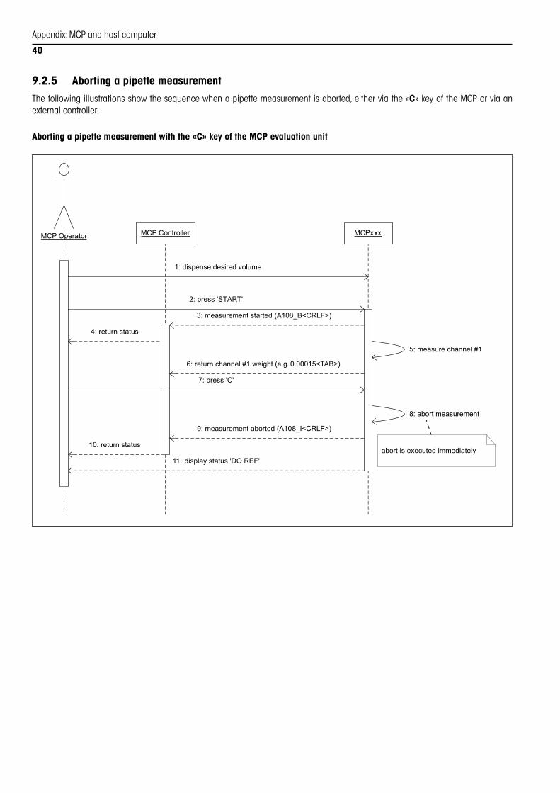
9.2.5 Aborting a pipette measurementThefollowingillustrationsshowthesequencewhenapipettemeasurementisaborted,eitherviathe«C»keyoftheMCPorviaanexternalcontroller.
Aborting a pipette measurement with the «C» key of the MCP evaluation unit
MCP Controller MCPxxxMCP Operator
1: dispense desired volume
5: measure channel #1
2: press 'START'
3: measurement started (A108_B<CRLF>)
6: return channel #1 weight (e.g. 0.00015<TAB>)
8: abort measurement
9: measurement aborted (A108_I<CRLF>)
7: press 'C'
abort is executed immediately
11: display status 'DO REF'
10: return status
4: return status

Appendix:MCPandhostcomputer
41
Aborting a pipette measurement via an external controller (external software)
MCP Controller MCPxxxMCP Operator
1: dispense desired volume
5: measure channel #1
2: press 'START'
3: measurement started (A108_B<CRLF>)
6: return channel #1 weight (e.g. 0.00015<TAB>)
10: abort measurement
11: measurement aborted (A108_I<CRLF>)
6: abort measurement
14: display status 'DO REF'
13: return status
8: stopping (A106_B<CRLF>)
7: stop (A106<CRLF>)
12: stopped (A106_A<CRLF>)
4: return status
9: return status

Appendix:MCPandhostcomputer
42
9.3 Data formatThefollowingexampleshowsatypicaldatarecordfortheMCP.Thisdatarecordresultedfromthemeasurement of an 8-channel pipettewithanadditionalsecondmeasurementofthefirstcontainer.
0.00015 0.00014 0.00016 0.00014 0.00016 0.00023 0.00015 0.00013 0.00012 g _ _ 1113153280
1 2 3 4 5 6 7 8 a b c d e
Value Meaning
1...n Weightvaluesoftheliquidpipettedinthecontainers(n=numberofpipettechannels,inthisexamplen=8)
a Weightvalueofthesecondmeasurementofcontainer1
b Unitofmeasurementofweightvalues(alwaysgram)
c Reservedforfutureuse,theplaceholder“_”isenteredinsteadofavalue
d Reservedforfutureuse,theplaceholder“_”isenteredinsteadofavalue
e SerialnumberoftheMCPfromwhichthedataistaken
Note
– AllvaluesareseparatedbytabsandthedatarecordisterminatedbyCRLF.
– Thenumberofdecimalplacesoftheweightvalues(4or5)dependsontheresolutionsettingoftheMCPwhichcanchangedwiththe«1/10d»keyorviaaspecificSICScommand(section9.4.3).Ifaparticularmeasurementandtheassociatedreferencevalueshaveadifferentnumberofdecimalplaces,thecorrespondingdatarecordwillalwaysbebasedonthelowernumberofdecimalplaces.
– Ifthesecondmeasurementofcontainer1wasdeactivatedinthemenu(section4.8),item“a”doesnothaveavalue.Inordertoensureuniformformattingofthedatarecords,theplaceholder“_”isenteredinstead.
9.4 MT SICS commandsThePCsoftwareandMCPinteractviaMTSICScommands,whichcanbeintegratedintoindividualapplications(MTSICS=METTLERTOLEDOStandardInterfaceCommandSet).
TheMCPsupportsarangeofstandardSICScommands,whicharelistedbrieflybelow(section9.4.2).Detailedinformationaboutthesecommandscanbefoundinthe“MT SICS Reference Manual”brochure(onlyavailableinEnglish,00705184).
Inadditiontostandardcommands,specific SICS commands also exist for the MCP.Thesecommandsarenotincludedinthe“MTSICSReferenceManual”butareexplainedindetailinsection9.4.3below.
9.4.1 Notes on the command formatSICScommandsconsistofoneormorecharactersfromtheASCIIcharacterset.Pleaseobservethenotesbelow:
• Enterthecommandusinguppercaselettersonly.
• Thepossibleparametersofthecommandmustbeseparatedfromoneanotherandfromthecommandnamebyaspace(ASCII32decimal,shownhereasï).
• EachcommandmustbeterminatedwithCRLF(ASCII13decimal,10decimal).

Appendix:MCPandhostcomputer
43
9.4.2 Standard SICS commandsTheMCPsupportsthefollowingcommandsfromthestandardSICScommandset:
– CommandsaccordingtoSICS Level 0: “I0”,“I1”,“I2”,“I3”,“I4”,“S”,“SI”,“SIR”,“Z”,“@”.
– CommandsaccordingtoSICS Level 1:“D”,“DW”,“K”,“SR”,“T”,“TA”,“TAC”,“TI”.(Note:Ifameasurementisinprogresswhilethe“D”commandisreceived,thetextwillappearintheMCPdisplayonlyafterthemeasurementhasbeencompleted).
– CommandsaccordingtoSICS Level 2: “C3”,“I11”.
Detailedinformationaboutthesecommandscanbefoundinthe“MT SICS Reference Manual”(onlyavailableinEnglish,00705184).
9.4.3 Specific SICS commands for the MCP
A105 – Position the rack and request the status
Command A105ïPosition Position:0...13 Targetposition,towhichtherackshouldbemoved(0=startposition,13=endposition).
Response A105ïB Commandisexecuted(theresponseisrepeatedeachtimeapositionispassed).
A105ïA Targetpositionreached.
A105ïL Incorrectnumberofparametersorparametersoutsidethepermis-siblevaluerange(0...13).
A105ïI Commandcannotbeexecuted(e.g.becauseapositioningcommandorameasurementprocessisalreadyinprogressorbecausethereisanerror).
Command A105 Requestthestatusoftherack.
Response A105ïAïPositionïError Position:0...13 Normalpositions99 Intermediateposition
Error:0 Noerror1 Initializationnotyetcompleted2 Incrementpulsegeneratortime-out3 Limitswitcherror
A105ïI Commandcannotbeexecuted(e.g.becauseapositioningcommandorameasurementprocessisinprogress).
A106 – Stop
Command A106 Stoptherackimmediately.Anymeasurementprocessthatisinprog-ressisthusaborted.
Response A106ïB Commandisexecuted.
A106ïA Drivestopped.
A106ïI Commandcannotbeexecuted.
Appendix:MCPandhostcomputer
44
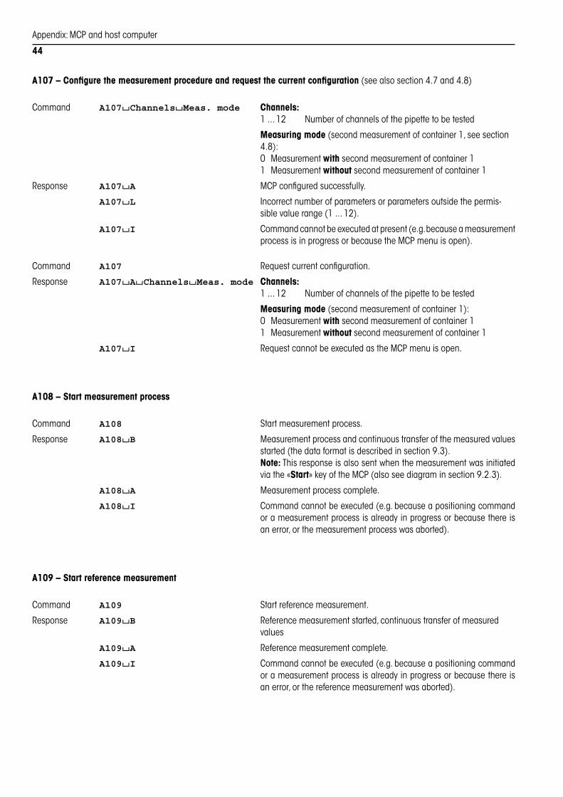
A107 – Configure the measurement procedure and request the current configuration(seealsosection4.7and4.8)
Command A107ïChannelsïMeas. mode Channels:1...12 Numberofchannelsofthepipettetobetested
Measuring mode(secondmeasurementofcontainer1,seesection4.8):0 Measurementwithsecondmeasurementofcontainer11 Measurementwithoutsecondmeasurementofcontainer1
Response A107ïA MCPconfiguredsuccessfully.
A107ïL Incorrectnumberofparametersorparametersoutsidethepermis-siblevaluerange(1...12).
A107ïI Commandcannotbeexecutedatpresent(e.g.becauseameasurementprocessisinprogressorbecausetheMCPmenuisopen).
Command A107 Requestcurrentconfiguration.
Response A107ïAïChannelsïMeas. mode Channels:1...12 Numberofchannelsofthepipettetobetested
Measuring mode(secondmeasurementofcontainer1):0 Measurementwithsecondmeasurementofcontainer11 Measurementwithoutsecondmeasurementofcontainer1
A107ïI RequestcannotbeexecutedastheMCPmenuisopen.
A108 – Start measurement process
Command A108 Startmeasurementprocess.
Response A108ïB Measurementprocessandcontinuoustransferofthemeasuredvaluesstarted(thedataformatisdescribedinsection9.3).
Note:Thisresponseisalsosentwhenthemeasurementwasinitiatedviathe«Start»keyoftheMCP(alsoseediagraminsection9.2.3).
A108ïA Measurementprocesscomplete.
A108ïI Commandcannotbeexecuted(e.g.becauseapositioningcommandorameasurementprocessisalreadyinprogressorbecausethereisanerror,orthemeasurementprocesswasaborted).
A109 – Start reference measurement
Command A109 Startreferencemeasurement.
Response A109ïB Referencemeasurementstarted,continuoustransferofmeasuredvalues
A109ïA Referencemeasurementcomplete.
A109ïI Commandcannotbeexecuted(e.g.becauseapositioningcommandorameasurementprocessisalreadyinprogressorbecausethereisanerror,orthereferencemeasurementwasaborted).
Appendix:MCPandhostcomputer
45
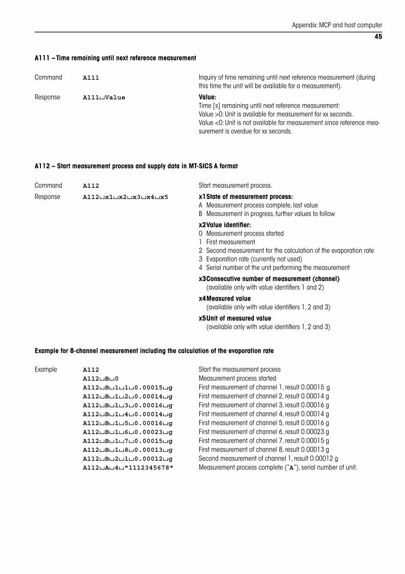
A111 – Time remaining until next reference measurement
Command A111 Inquiryoftimeremaininguntilnextreferencemeasurement(duringthistimetheunitwillbeavailableforameasurement).
Response A111ïValue Value:Time[s]remaininguntilnextreferencemeasurement:Value>0:Unitisavailableformeasurementforxxseconds.Value<0:Unitisnotavailableformeasurementsincereferencemea-surementisoverdueforxxseconds.
A112 – Start measurement process and supply data in MT-SICS A format
Command A112 Startmeasurementprocess.
Response A112ïx1ïx2ïx3ïx4ïx5 x1 State of measurement process:A Measurementprocesscomplete,lastvalueB Measurementinprogress,furthervaluestofollow
x2 Value identifier:0 Measurementprocessstarted1 Firstmeasurement2 Secondmeasurementforthecalculationoftheevaporationrate3 Evaporationrate(currentlynotused)4 Serialnumberoftheunitperformingthemeasurement
x3 Consecutive number of measurement (channel) (availableonlywithvalueidentifiers1and2)
x4 Measured value (availableonlywithvalueidentifiers1,2and3)
x5 Unit of measured value (availableonlywithvalueidentifiers1,2and3)
Example for 8-channel measurement including the calculation of the evaporation rate
Example A112 Startthemeasurementprocess A112ïBï0 Measurementprocessstarted A112ïBï1ï1ï0.00015ïg Firstmeasurementofchannel1,result0.00015 g A112ïBï1ï2ï0.00014ïg Firstmeasurementofchannel2,result0.00014g A112ïBï1ï3ï0.00016ïg Firstmeasurementofchannel3,result0.00016g A112ïBï1ï4ï0.00014ïg Firstmeasurementofchannel4,result0.00014g A112ïBï1ï5ï0.00016ïg Firstmeasurementofchannel5,result0.00016g A112ïBï1ï6ï0.00023ïg Firstmeasurementofchannel6,result0.00023g A112ïBï1ï7ï0.00015ïg Firstmeasurementofchannel7,result0.00015g A112ïBï1ï8ï0.00013ïg Firstmeasurementofchannel8,result0.00013g A112ïBï2ï1ï0.00012ïg Secondmeasurementofchannel1,result0.00012g A112ïAï4ï"1112345678" Measurementprocesscomplete(“A”),serialnumberofunit.

Appendix:MCPandhostcomputer
46
A113 – Configure the time interval for reference measurement(refertosection4.10)
Command A113ïTime Time:1...10 maximumadmissibletimeinterval(inminutes)betweentworeferencemeasurements.
Response A113ïA Timeintervalforreferencemeasurementconfiguredsuccessfully.
A113ïL Incorrectnumberofparametersorparametersoutsidethepermis-siblevaluerange(1...10).
A113ïI Commandcannotbeexecutedatpresent(e.g.becauseameasurementprocessisinprogressorbecausetheMCPmenuisopen).
Command A113 Requestcurrenttimeintervalforreferencemeasurement.
Response A113ïAïTime Time:1...10 Currenttimeintervalinminutes
A113ïI RequestcannotbeexecutedastheMCPmenuisopen.
A114 – Switch the resolution of measured values(1/10d,seethenotesinsections5.3.3,5.4.2and9.3)
Command A114ïValue Value:0 1digitresolutionofmeasuredvalues(5decimalplaces)1 10digitsresolutionofmeasuredvalues(4decimalplaces).
Response A114ïA Resolutionofmeasuredvaluesconfiguredsuccessfully.
A114ïL Incorrectnumberofparametersorparametersoutsidethepermis-siblevaluerange(0or1).
A114ïI Commandcannotbeexecutedatpresent(e.g.becauseameasurementprocessisinprogressorbecausetheMCPmenuisopen).
Command A114 Requestcurrentresolutionofmeasuredvalues.
Response A114ïAïValue Value:0 Resolutionofmeasuredvaluesis1digit(5decimalplaces)1 Resolutionofmeasuredvaluesis10digits(4decimalplaces)
A114ïI RequestcannotbeexecutedastheMCPmenuisopen.

Appendix:MCPandhostcomputer
47
A115 – Configure the vibration adapter(seesection4.4)
Command A115ïValue Value:1 Settingforextremelystableenvironments2 Settingforstableenvironments3 Settingforunstableenvironments.
Response A115ïA Vibrationadapterconfiguredsuccessfully.
A115ïL Incorrectnumberofparametersorparametersoutsidethepermis-siblevaluerange(1...3).
A115ïI Commandcannotbeexecutedatpresent(e.g.becauseameasurementprocessisinprogressorbecausetheMCPmenuisopen).
Command A115 Requestcurrentsettingofthevibrationadapter.
Response A115ïAïValue Value:1 Settingforextremelystableenvironments2 Settingforstableenvironments3 Settingforunstableenvironments.
A115ïI RequestcannotbeexecutedastheMCPmenuisopen.
A116 – Configure the process adapter(seesection4.5)
Command A116ïValue Value:0 Processadapterswitchedoff(“OFF”),recommendedsettingfor MCP1 Notrecommended,mayaffectthemeasuringperformance!2 Notrecommended,mayaffectthemeasuringperformance!3 Notrecommended,mayaffectthemeasuringperformance!
Response A116ïA Processadapterconfiguredsuccessfully.
A116ïL Incorrectnumberofparametersorparametersoutsidethepermis-siblevaluerange(0...3).
A116ïI Commandcannotbeexecutedatpresent(e.g.becauseameasurementprocessisinprogressorbecausetheMCPmenuisopen).
Command A116 Requestcurrentsettingoftheprocessadapter.
Response A116ïAïValue Value:0 Processadapterswitchedoff(“OFF”),recommendedsettingfor MCP1 Notrecommended,mayaffectthemeasuringperformance!2 Notrecommended,mayaffectthemeasuringperformance!3 Notrecommended,mayaffectthemeasuringperformance!
A116ïI RequestcannotbeexecutedastheMCPmenuisopen.

Appendix:MCPandhostcomputer
48
A117 – Select the repeatability(seesection4.6)
Command A117ïValue Value:0 Functionswitchedoff,eachmeasurementvalueisconsidered stableandreleasedimmediately(“OFF”)1 Veryquickreleaseofthemeasurementvalue(“Std”)2 Quickreleaseofthemeasurementvalue(“Good”)3 Slowreleaseofthemeasurementvalue(“bEttEr”)4 Oncestabilityhasbeenachieved,themeasurementvalueis onlyreleasedifithasnotchangedforafewseconds (“bESt”).
Response A117ïA Repeatabilityconfiguredsuccessfully.
A117ïL Incorrectnumberofparametersorparametersoutsidethepermis-siblevaluerange(0...4).
A117ïI Commandcannotbeexecutedatpresent(e.g.becauseameasurementprocessisinprogressorbecausetheMCPmenuisopen).
Command A117 Requestcurrentsettingoftherepeatability.
Response A117ïAïValue Value:0 Functionswitchedoff,eachmeasurementvalueisconsidered stableandreleasedimmediately(“OFF”)1 Veryquickreleaseofthemeasurementvalue(“Std”)2 Quickreleaseofthemeasurementvalue(“Good”)3 Slowreleaseofthemeasurementvalue(“bEttEr”)4 Oncestabilityhasbeenachieved,themeasurementvalueis onlyreleasedifithasnotchangedforafewseconds (“bESt”).
A117ïI RequestcannotbeexecutedastheMCPmenuisopen.

Recommendationsforpracticaluse
49
10 Recommendations for practical useWe recommend the following preventive maintenance work to keep the measuring performance of the MCP at top level:
Keeptheunitcleananddry.Distilledordeionizedwaterisveryaggressiveandcausessuperficialcorrosion(rustfilm)towetmetallicsurfacesevenifthesearemadeofhigh-qualitystainlesssteel.
10.1 Internal calibrationOnceaday,preferablyinthemorningbeforethefirstmeasurement,theMCPshouldbecalibratedinternally(pressandhold«Cal»key,seesection5.1).DonotdisconnecttheMCPfromthemainswhentheunitisnotused.WhentheunitwasdisconnectedfromthemainsorincaseofpowerfailuremakesuretolettheMCPwarmupforatleast60minutesbeforeperformingmeasurements.
10.2 Verification of the weighing cell calibrationAfteracertainperiodoftime(dependingtocustomer’sparticularrequirements)theMCP’sinternalcalibrationshouldbeverifiedwithanexternalweightusingtheoptionalcalibrationkit(orderinginformationisfoundinsection8.8).Theverificationintervaltobedefinedbythecustomerismeanttolimitpossibleinformationcampaignsorrecallactionsthatmaybemandatoryincaseofmeasurementerrors.Section11explainshowtousetheoptionalcalibrationkit.
MaximumadmissiblecalibrationtolerancesoftheMCPforpipettecalibrationaccordingtoISO8655:
Application tolerances measuredwith20 gF1orbetter(E2)
Tolerancefor0.03 %(alertlimit) 0.00700 g
Tolerancefor0.10 %(actionlimit) 0.02100 g
Thecalibrationtolerancevaluesmentionedaboveensurethatallpipettecalibrations(single-channelormultichannel)meettheISO8655requirementsevenincasethetolerancesspecifiedbythepipettemanufacturerareuptofivetimesmorerestrictive.
When will it be necessary to inform your clients in case of measurement errors?
Incasethe0.10%toleranceisexceeded,youshouldfirstverifytherealimpactonpipettecalibration.If,forexample,theadmissibletoleranceforbalancecalibrationerrorsisexceededbyafactorof10(i.e.1%),thisjustmeansthatthepipettecalibrationdatastatedinthecalibrationprotocolsaretoohighortoolowby1%.Dependingoncustomer’squalitystandardsthismayormaynotjustifyarecallaction.
10.3 Excess evaporationIfyouencounterexcessevaporationalthoughtheMCPisoperatedwellwithinthespecifiedambientconditions,thefollowingproblemmaybepresent:Ifthecontainersareoverfilledorhavebeeninclined,followingtransportationorafterthetubeshavebeenremoved,theremayberesidualwaterintheareawherethetubeentersthecontainer.Thisresidualliquidmaycausecapillaryactionthatmovesthewateroutofthecontainerwhichleadstoexcessevaporation.Inthiscase,removetheglasstubefromthecontainer(section7).UseKleenexorothersuitablecleaningpapertocarefullydrytheoutsideofthetubeaswellasthetubeguideintheupperpartofthecontainer,thenrelocatethetube.Preventoverfillingorincliningthecontainers.Checkthecriticalarea(wheretheglasstubeentersthecontainer)onaregularscheduleanddry,asrequired.

Workingwiththeoptionalcalibrationkit
50
11 Working with the optional calibration kitTheoptionalcalibrationkit(orderinginformationseesection8.8) isusedtoverify the internalcalibrationof theMCP.Thissectiondescribestheinstallationanduseoftheoptionalcalibrationkit.Informationonthefrequencyofverificationsandthetolerancesarefoundinsection10.
11.1 Contents of the calibration kitThecalibrationkitissuppliedinaplasticcaseandincludesthefollowingitems:
1 Centeringring
2 Weighingpan
3 Draftshield
4 Coverglass
5 Calibrationweight20 ginprotectivebox(certificateincluded)
6 Tweezersinsleeve
11.2 Installation of the calibration kitSwitchtheMCPoffandremoveallassemblypartsformthemeasuringunit(containers,rack,weighingyoke,etc.).
Installthecenteringring.
1
2
3
4
5 6

Workingwiththeoptionalcalibrationkit
51
=O0000e
Mounttheweighingpan.
Installthedraftshieldandputonthecoverglass.
11.3 Carrying out the verification
Brieflypressthe«k»keytoresettheMCPdisplaytozero.
Liftoffthedraftshieldandcoverglass,thenusethetweezerstolocatethecalibrationweight(20 g)exactlyatthecenteroftheweighingpan.Relocatethedraftshieldandthecoverglass.

Workingwiththeoptionalcalibrationkit
52
Waituntilthedisplayreachesstability,thennotetheweightvaluedisplayed.
Removethecalibrationweight,thenperformaninternalcalibra-tion(section5.1).
Uponcompletionoftheinternalcalibration,resettheMCPdisplaytozeroandputonthecalibrationweightagain.Oncethedisplayreachesstability,theweightvaluemustbewithintheadmissibletolerances(applicationtolerancesseesection10,specificationsof theweighingmoduleseesection8.1). If thevalue isoutofeithertoleranceyoushouldcontacttheMETTLERTOLEDOservicedepartmentwithoutdelay.
1)99999e
CAL donE
CAL int
1)99996e


To protect your METTLER TOLEDO product’s future:METTLER TOLEDO Service assures the quality, measuring accuracy and preservation of value of all METTLER TOLEDO products for years to come.Please send for full details about our attractive terms of service. Thank you.
Subjecttotechnicalchangesandtotheavailabilityoftheaccessoriessuppliedwiththeinstruments.
©Mettler-ToledoAG200611780744BPrintedinSwitzerland0610/2.12
Mettler-Toledo AG, Laboratory & Weighing Technologies,CH-8606Greifensee,SwitzerlandPhone+41-1-9442211,Fax+41-1-9443060,Internet:http://www.mt.com
*11780744*