TYPE MCP 4/01 · mcp-om-mcp4/01 issue 06 installation & operating manual page 1 mcp equipment unit...
32
MCP-OM-MCP4/01 ISSUE 06 OPERATING MANUAL TYPE MCP 4/01 UNIT 8 - WHITEBRIDGE INDUSTRIAL ESTATE STONE STAFFORDSHIRE ST15 8LQ ENGLAND TEL: +44 (0) 1785 815651 FAX: +44 (0) 1785 812115
Transcript of TYPE MCP 4/01 · mcp-om-mcp4/01 issue 06 installation & operating manual page 1 mcp equipment unit...

MCP-OM-MCP4/01 ISSUE 06
OPERATING MANUAL
TYPE MCP 4/01
UNIT 8 - WHITEBRIDGE INDUSTRIAL ESTATE STONE
STAFFORDSHIRE ST15 8LQ ENGLAND
TEL: +44 (0) 1785 815651 FAX: +44 (0) 1785 812115

MCP-OM-MCP4/01 ISSUE 06 INSTALLATION & OPERATING MANUAL Page 1
MCP EQUIPMENT UNIT 8, WHITEBRIDGE INDUSTRIAL ESTATE - STONE - STAFFORDSHIRE ST15 8LG
ENGLAND TEL. (+44) 01785 815651 - FAX. (+44) 01785 812115
Email: [email protected] - Web:
A DIVISION OF MINING & CHEMICAL PRODUCTS LTD. Thank you for choosing an MCP vacuum casting machine. The equipment, which is controlled by a PLC, combines a vacuum pump with fast exhaust rate and a highly efficient mixing unit to ensure the production of premium quality castings in a variety of moulding materials. The vacuum chamber itself is used for de-gassing both the silicone rubber mixture from which moulds are formed, and the two-component MCP resins used for the actual castings. Please follow carefully the instructions for installation and use that are to be found in this Operating Manual, which also covers routine checks and adjustments. A separate SERVICE MANUAL is provided to deal with specific repairs, fault-finding and replacements. A further Manual, VACUUM CASTING TECHNIQUE, gives an overview of the system. A copy is supplied with every machine.
HEALTH AND SAFETY All units supplied on or after 1st January, 1995, bear the CE mark. The Declaration of Conformity will be found at the end of this Manual.
ELECTRICAL SAFETY Certain tasks described in this manual require access to the electrical control enclosure, and should therefore be carried out only by a suitably qualified person.
MATERIALS SAFETY DATA Though no special hazard is likely when they are used in accordance with the suppliers’ recommendations, each of the materials used in the process is the subject of a Safety Data Sheet, supplied at the time of first purchase and giving information in conformity with both European Directive 91/155/EEC and (in the United Kingdom) the Consumer Protection Act 1987.
NOISE The equivalent continuous A-weighted sound-pressure level during working of this machines does not exceed 70dB(A).

MCP-OM-MCP4/01 ISSUE 06 INSTALLATION & OPERATING MANUAL Page 2
CONTENTS
Page INSTALLATION
Weight and dimensions 8 Power requirements 8 Siting the machine 8 Installation sequence 8-9 SAFE WORKING PRACTICES 10 PREPARATION FOR CASTING 14 Preparing the mould and flow-system Preparing the resin Fitting the cups and paddle WORKING PROCEDURES 15 To make the machine ready for use Operating modes / Control Panel Touch Screen Functions Operating in manual mode Using the automatic operating sequence Stopping in emergency Re-starting after emergency Shutting down
CONTROL PANEL TOUCH SCREEN FUNCTIONS 17
Manual functions Auto functions APPENDIX 26 ROUTINE MAINTENANCE PROCEDURES 29 DECLARATION OF CONFORMITY 31 Illustrations Fig. 1 General front view 3 Fig. 2 General view with chamber open 4 Fig. 3 Rear view with access panel open 5 Fig. 4 Lifting Bolts in position 8 Fig. 4a Operating Panel 8 Fig. 5 Adjusting the paddle and holder 9 Fig. 6 Arrangement of the mould and accessories 10 Standard accessories: Illustrations and Part Numbers 6-7

MCP-OM-MCP4/01 ISSUE 06 INSTALLATION & OPERATING MANUAL Page 3
VACUUM CASTING MACHINE TYPE MCP 4/01
Fig. 1 General front view
Main isolator switch (Red/yellow) Re-set button (green) Lockable door-catches (Side access panel) Lockable door-catch (Pump access area)
Emergency Stop Pushbutton Control Panel

MCP-OM-MCP4/01 ISSUE 06 INSTALLATION & OPERATING MANUAL Page 4
VACUUM CASTING MACHINE TYPE MCP 4/01
Cup A
Fig. 2 General view with chamber open
Stirrer motor assembly
Cup B
Funnel platform
Lower (mould) chamber

MCP-OM-MCP4/01 ISSUE 06 INSTALLATION & OPERATING MANUAL Page 5
VACUUM CASTING MACHINE TYPE MCP 4/01
Fig. 3 Side view with access panel open
MCP-OM-MCP4/01 ISSUE 06 INSTALLATION & OPERATING MANUAL Page 6
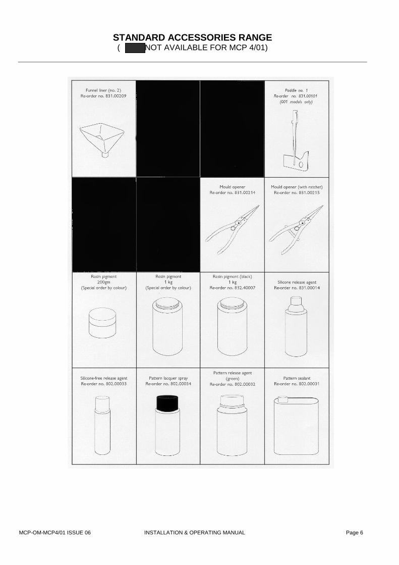
STANDARD ACCESSORIES RANGE ( NOT AVAILABLE FOR MCP 4/01)
MCP-OM-MCP4/01 ISSUE 06 INSTALLATION & OPERATING MANUAL Page 7
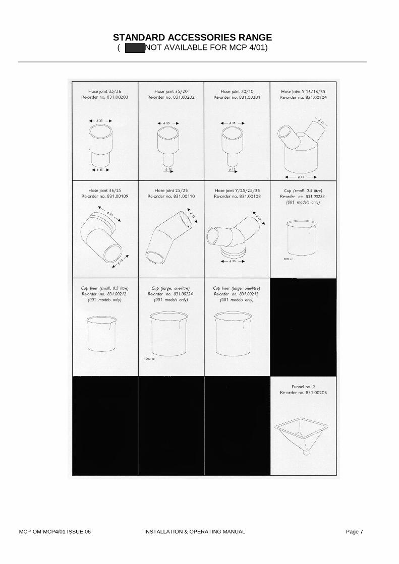
STANDARD ACCESSORIES RANGE ( NOT AVAILABLE FOR MCP 4/01)

MCP-OM-MCP4/01 ISSUE 06 INSTALLATION & OPERATING MANUAL Page 8
INSTALLATION
WEIGHT AND DIMENSIONS * Weight: shipping weight, 336kg; unpacked 270kg External dimensions (mm): 1200 high x 900 wide x 610 front-to-back. POWER REQUIREMENTS
* The unit requires a single-phase, 230 volt supply. Normal current rating, 10A; maximum surge 16A.
In countries of the European Union, units are supplied with the appropriate plug, fused as necessary. * An earthing point and a circuit breaker must be provided. Recommended size 20A.
SITING THE MACHINE
* Do not site the unit in an area subject to excessive heat or high humidity.
* Choose a well-ventilated room. If possible, provide local exhaust ventilation to an outside vent.
* Avoid areas exposed to dust or vibration. * If required, the complete unit may be lifted by using the two
supplied D-bolts connected to the vacuum chamber as shown in Fig.4 under the top cover plate.
* Ensure that the unit stands on a level surface (adjustable
feet are not provided)
INSTALLATION SEQUENCE
Before installing, please read through the instructions and ensure that you can identify each of the parts referred to. Note that access to the main electrical panel is by the lockable side panel on the right-hand side of the cabinet.
1. Open the vacuum pump access panel. Check the oil level
and, if necessary, fill the vacuum pump to the level indicated by a mark on the sight glass using the oil supplied. Close the access panel
2. Ensure that the main isolator is set to ‘OFF’ and that the
Emergency Stop, shown, (fig. 4a) is pushed into the ‘OFF’ position.
3. Open the side electrical access panel and ensure that the
circuit breaker switch is in the ‘up’ position (i.e. switched on). Make and check the earth connection to the unit. Close the access panel.
4. Connect to the power supply, using the cable and plug
supplied. Switch on at the main isolator switch. 5. Release the Emergency Stop knob by turning it anti-clockwise.
6. Press the ‘Re-set’ (green) button (at the top right side corner of the machine).
Fig. 4a Operating panel
Fig. 4 Lifting Bolts in position.

MCP-OM-MCP4/01 ISSUE 06 INSTALLATION & OPERATING MANUAL Page 9
INSTALLATION continued
7. Check that the chamber illumination light is now on. If it is not, turn off the machine at the isolator, open the side access panel and check the light bulb.
8. Insert and adjust the mixing paddle (fig. 5).
9. The slow leak valve is accessible from the back panel (fig. 3). Check the adjustment of the flow-control governed by this device. The valve handle should be inclined at approximately 45o to the valve body.
WARNING
DO NOT operate the vacuum pump for longer than 30 seconds while the vacuum chamber is open. Failure to
observe this precaution might result in excessive wear on the pump’s components.
Note that the paddle has a slot (1) which fits over a pin within the slot in its holder and is retained by pressure from a spring-loaded steel ball. The locked grubscrew (2) that carries the ball may be adjusted (using an M6 spanner and 3mm AF Allen key): it should be possible to remove and replace the paddle by hand, without slackness when it is in position.
A cup and liner should be in position while height adjustment is made. To adjust the height, use a 2mm AF Allen key to slacken the grubscrew (3) to allow the holder to slide up or down the shaft. When correctly positioned, the paddle should rotate with a clearance of 1-2 mm from the cup liner. Re-tighten the grubscrew.
Fig. 5 Adjusting the paddle and holder

MCP-OM-MCP4/01 ISSUE 06 INSTALLATION & OPERATING MANUAL Page 10
SAFE WORKING PRACTICES Users of equipment should satisfy themselves that they comply with the requirements of the relevant legislation within the United Kingdom (or equivalent regulations within the country of use). Particular attention is drawn to the following:-
• Health and Safety at Work etc. Act 1974;
• Personal protective Equipment at Work Regulations 1992;
• Provision and Use of Work Equipment Regulations 1998;
Provision and Use of Work Equipment Regulations In general terms, the Regulations require that equipment provided for use at work is:
• Suitable for the intended use;
• Safe for use, maintained in a safe condition and, in certain circumstances, inspected to ensure this remains the case;
• Used only by people who have received adequate information, instruction and training; and;
• Accompanied by suitable safety measures, e.g. protective devices, markings and warnings.
Personal Protective Equipment Users should be aware of the requirements of the Personal Protective Equipment at Work Regulations 1992 when providing equipment. The main requirements of the PPE at Work Regulations 1992 is that personal protective equipment is to be supplied and used at work wherever there are risks to health and safety that cannot be adequately controlled in other ways. Because the effectiveness of PPE can easily be compromised, e.g. by not being worn properly, it should always be considered as a last resort and only used where other precautions cannot adequately reduce the risk of injury. Even where engineering controls and safe systems of work have been applied, some hazards might remain. In considering methods of safeguarding machinery the use of personal protective equipment may be used to minimise the risk of injury. This includes the need for special clothing, including footwear, hearing, eye and respiratory protection. The guidance shown below may be used to consider the risks which may or may not be present. The user should make his own assessment of risks depending upon the circumstances of use.

MCP-OM-MCP4/01 ISSUE 06 INSTALLATION & OPERATING MANUAL Page 11
SAFE WORKING PRACTICES CONTINUED
Hazards Options HANDS
Abrasion; Temperature extremes; cuts and punctures; impact; chemicals; skin irritation.
Gloves, gauntlets Notes: • Don’t wear gloves when operating
machines where gloves might get caught. • Care in selection is needed.
EYES
Chemical or metal splash; dust; projectiles.
Spectacles, goggles, visors. Notes: • Make sure the eye protection chosen has
the right combination of protection for the task.
FEET
Wet; slipping; falling objects; heavy loads; metal and chemical slash
Safety boots and shoes. Notes: • Consider conditions of use.
BODY
Heat; chemical or metal splash; spray from pressure leaks; impact; entanglement of own clothing.
Conventional or disposable overalls, aprons. Notes: • Consider choice of materials in relation to
the chemicals involved.
RESPIRATORY
Dusts; gases and vapours.
Disposable respirators, half masks or full face masks, powered respirators. Notes: • The right type of respiratory must be used
for the substance being handled.
HEARING
Impact noise; intensities; pitch.
Ear plugs or defenders. Notes: • See Noise at Work Regulations 1989.
NOTE: Use personal protective equipment only as a last resort. Wherever possible engineering controls and safe systems of work should be used instead. All those required to wear protective equipment should be given training in its proper use, care and maintenance.
MCP-O
SAFE WORKING PRACTICES CONTINUED
Not classified as hazardous
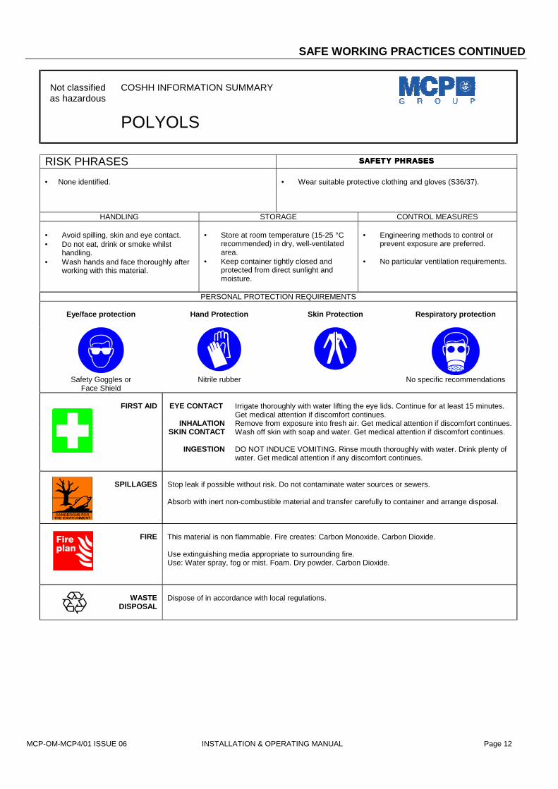
COSHH INFORMATION SUMMARY
POLYOLS
RISK PHRASES SAFETY PHRASESSAFETY PHRASESSAFETY PHRASESSAFETY PHRASES • None identified.
• Wear suitable protective clothing and gloves (S36/37).
HANDLING STORAGE CONTROL MEASURES • Avoid spilling, skin and eye contact. • Do not eat, drink or smoke whilst
handling. • Wash hands and face thoroughly after
working with this material.
• Store at room temperature (15-25 °C
recommended) in dry, well-ventilated area.
• Keep container tightly closed and protected from direct sunlight and moisture.
• Engineering methods to control or
prevent exposure are preferred. • No particular ventilation requirements.
PERSONAL PROTECTION REQUIREMENTS
Eye/face protection
Hand Protection
Skin Protection
Respiratory protection
Safety Goggles or Face Shield
Nitrile rubber No specific recommendations
EYE CONTACT
Irrigate thoroughly with water lifting the eye lids. Continue for at least 15 minutes. Get medical attention if discomfort continues.
INHALATION Remove from exposure into fresh air. Get medical attention if discomfort continues. SKIN CONTACT Wash off skin with soap and water. Get medical attention if discomfort continues.
FIRST AID
INGESTION DO NOT INDUCE VOMITING. Rinse mouth thoroughly with water. Drink plenty of water. Get medical attention if any discomfort continues.
SPILLAGES
Stop leak if possible without risk. Do not contaminate water sources or sewers. Absorb with inert non-combustible material and transfer carefully to container and arrange disposal.
FIRE
This material is non flammable. Fire creates: Carbon Monoxide. Carbon Dioxide.
M-MCP4/01 ISSUE 06 INSTALLATION & OPERATING MANUAL Page 12
Use extinguishing media appropriate to surrounding fire. Use: Water spray, fog or mist. Foam. Dry powder. Carbon Dioxide.
WASTE DISPOSAL
Dispose of in accordance with local regulations.
MCP-OM
SAFE WORKING PRACTICES CONTINUED
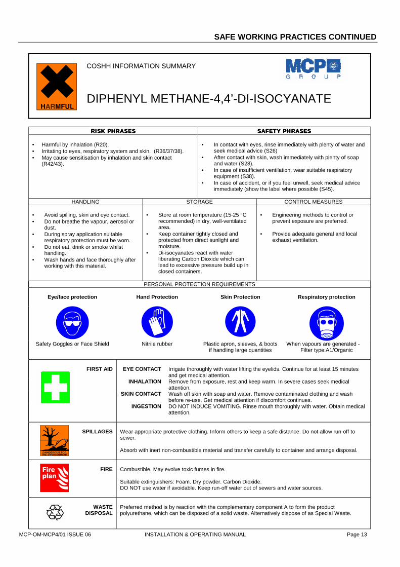
COSHH INFORMATION SUMMARY
DIPHENYL METHANE-4,4’-DI-ISOCYANATE
RISK PHRASESRISK PHRASESRISK PHRASESRISK PHRASES SAFETY PHRASESSAFETY PHRASESSAFETY PHRASESSAFETY PHRASES
• Harmful by inhalation (R20). • Irritating to eyes, respiratory system and skin. (R36/37/38). • May cause sensitisation by inhalation and skin contact
(R42/43).
• In contact with eyes, rinse immediately with plenty of water and
seek medical advice (S26) • After contact with skin, wash immediately with plenty of soap
and water (S28). • In case of insufficient ventilation, wear suitable respiratory
equipment (S38). • In case of accident, or if you feel unwell, seek medical advice
immediately (show the label where possible (S45).
HANDLING STORAGE CONTROL MEASURES • Avoid spilling, skin and eye contact. • Do not breathe the vapour, aerosol or
dust. • During spray application suitable
respiratory protection must be worn. • Do not eat, drink or smoke whilst
handling. • Wash hands and face thoroughly after
working with this material.
• Store at room temperature (15-25 °C
recommended) in dry, well-ventilated area.
• Keep container tightly closed and protected from direct sunlight and moisture.
• Di-isocyanates react with water liberating Carbon Dioxide which can lead to excessive pressure build up in closed containers.
• Engineering methods to control or
prevent exposure are preferred. • Provide adequate general and local
exhaust ventilation.
PERSONAL PROTECTION REQUIREMENTS
Eye/face protection
Hand Protection
Skin Protection
Respiratory protection
Safety Goggles or Face Shield Nitrile rubber Plastic apron, sleeves, & boots if handling large quantities
When vapours are generated - Filter type:A1/Organic
EYE CONTACT
Irrigate thoroughly with water lifting the eyelids. Continue for at least 15 minutes and get medical attention.
INHALATION Remove from exposure, rest and keep warm. In severe cases seek medical attention.
SKIN CONTACT Wash off skin with soap and water. Remove contaminated clothing and wash before re-use. Get medical attention if discomfort continues.
FIRST AID
INGESTION DO NOT INDUCE VOMITING. Rinse mouth thoroughly with water. Obtain medical attention.
SPILLAGES
Wear appropriate protective clothing. Inform others to keep a safe distance. Do not allow run-off to sewer. Absorb with inert non-combustible material and transfer carefully to container and arrange disposal.
FIRE
Combustible. May evolve toxic fumes in fire. Suitable extinguishers: Foam. Dry powder. Carbon Dioxide. DO NOT use water if avoidable. Keep run-off water out of sewers and water sources.
WASTE
Preferred method is by reaction with the complementary component A to form the product
-MCP4/01 ISSUE 06 INSTALLATION & OPERATING MANUAL Page 13
DISPOSAL polyurethane, which can be disposed of a solid waste. Alternatively dispose of as Special Waste.

MCP-OM-MCP4/01 ISSUE 06 INSTALLATION & OPERATING MANUAL
PREPARATION FOR CASTING
The sequence of operations (explained in general terms in the companion Manual VACUUM CASTING TECHNIQUE) requires the resin component cups, the whisk for mixing, a funnel and hoses all to be put correctly into place above the entrance gate(s) to the mould.
PREPARING THE MOULD AND FLOW-SYSTEM The standard accessory range includes several joints (see page 5), which may be employed in conjunction with clear plastic hose to direct the mixed resin into the mould, with the flow being spilt through Y-joints if need be .
FITTING THE CUPS AND PADDLE Fit the cups into their cradles, ensuring always that component ‘A’ is in cup ‘A’ (the upper right(a) Place cup A in its cradle, engaging the spout with the V-shaped cut-out. Ensure tha
that of it’s liner, if used) is beneath the lip of the retaining clip. (b) Remove the paddle from its clip (above cup B). (c) Pull open the retainer assembly (with V-shaped cut-out) for cup B. Slide the cup B i
that the lip of the cup (and that of it’s liner, if used) is beneath the lip of the retaining cof the cradle. Close up the retainer place, keeping the spout of the cup in the V-shapturning anti-clockwise the knob at its left.
Re-fit the paddle by sliding it into its holder, ensuring that it is fully engaged by the spring-loade
BEFORE BEGINNING A CASTING, ALWAYS HAVE READY THAPPROPRIATE SOLVENT FOR CLEANING UP RESIDUAL RES
Fit the funnel (see fig. 7) into the centre of the carriage in the upper part of the chamber, locating the front edge over the guard plate on the funnel position, and place the prepared mould (on a support platform in necessary) in the lower chamber. NB – do not use any form of support that might inflate under vacuum. Decide on the pattern and sizes of hose and any connectors that may be needed, keeping the runs as short as conveniently possible. Prepare the hose outlets, fixing to both funnel and mould. Ensure that you obtain a good fit, but one that is not too tight. Leave no end open. PREPARING THE RESIN Two- or three-component resins should be prepared in accordance with the supplier’s instructions and placed in the appropriate cups. Although casting may be carried out without them, it is recommended that cup liners be always used. For general guidance, refer to the manual Vacuum Casting Technique: a guide for new users supplied with the machine.
Fig. 6 Arrangement of t
he mould and accessories
Page 14
cup). t the lip of the cup (and
nto the cradle, ensuring lips at the side and rear ed cut-ut, and lock it by
d ball.
E IN.

MCP-OM-MCP4/01 ISSUE 06 INSTALLATION & OPERATING MANUAL Page 15
WORKING PROCEDURES 1. TO MAKE THE MACHINE READY FOR USE
Switch on the machine at the isolator. Press the green re-set button (the inside of the chamber is now illuminated). The machine is now ready for use.
ALWAYS CHECK THAT BOTH RESIN COMPONENTS –
AND THE MOULD – ARE IN POSITION BEFORE ATTEMPTING TO MIX AND CAST
2. OPERATING MODES
The machine can be operated entirely in manual mode or auto (fig. 16).
KEEP YOUR HANDS OUT OF THE VACUUM CHAMBER WHILE ANY OF THE MECHANISMS ARE OPERATING
3. OPERATING IN MANUAL MODE
Select the manual screen. Press ‘Pump’ to begin chamber evacuation. Press ‘Speed’ to select the mixing speed. Press ‘Run’ to start the mixing of part B. Once the vacuum time has been achieved, stop the mixer. Press ‘A’ cup down, allowed resin ‘A’ to drain into cup ‘B’ Press ‘A’ cup up. Re-start the mixer. When the mixing is complete, stop the mixer and tilt cup ‘B’ by pressing its DOWN button. Allow it to drain before pressing the UP button to return cup ‘B’ to up position. When the pouring is complete and the resin has settled, press the SLOW LEAK button. The slow leak will start to force the resin further into the mould. This should be continued for up to 30 seconds, after which pressing the FAST LEAK button will release the remaining vacuum fully, forcing the resin completely into the mould.
4. USING THE AUTOMATIC OPERATION SEQUENCE
With the mould, accessories and resin components all in place, close the chamber doors. Select required program Go to AUTO REPLAY Start the program.
5. STOPPING IN AN EMERGENCY
To deal with unforeseen or unplanned steps in operation (for example, forgetting to load with a resin component, or an apparent malfunction as a result of faulty programming): Operate the red STOP button (it will lock into place) The machine is now completely shut down: nothing with operate.

MCP-OM-MCP4/01 ISSUE 06 INSTALLATION & OPERATING MANUAL Page 16
WORKING PROCEDURES continued 6. RE-STARTING AFTER EMERGENCY
Rotate and release the red STOP button Press the green re-set button Press ‘Esc’ to return to the main screen.
The machine can now be operated again. Gain access to the chamber after first operating the FAST LEAK control to release the vacuum. It will then be possible to correct any fault before continuing.
7. SHUTTING DOWN
Complete shutdown: turn off the power supply at the isolator switch.
AFTER CASTING – A REMINDER
Remove the cups and liners, the funnel and the pipes as soon as possible and clean them out with the recommended solvent,
ready for re-use.
MCP-OM-MCP4/01 ISSUE 06 INSTALLATION & OPERATING MANUAL Page 17
WORKING PROCEDURES continued CONTROL PANEL TOUCH SCREEN FUNCTIONS
It should be noted that the PLC software is protected by a battery backed supply. This battery is guaranteed for 5 years. Also access to the software is also protected by a secure password system.
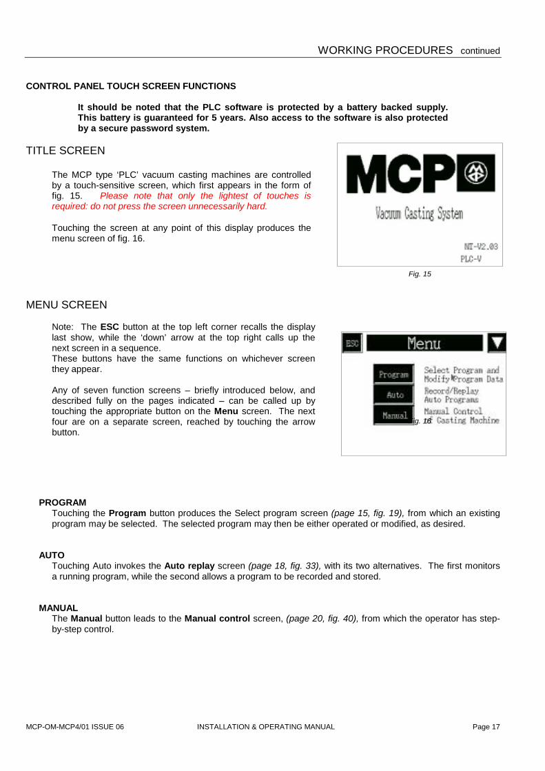
TITLE SCREEN
The MCP type ‘PLC’ vacuum casting machines are controlled by a touch-sensitive screen, which first appears in the form of fig. 15. Please note that only the lightest of touches is required: do not press the screen unnecessarily hard.
Touching the screen at any point of this display produces the menu screen of fig. 16.
MENU SCREEN
Note: The ESC button at the top left corner recalls the display last show, while the ‘down’ arrow at the top right calls up the next screen in a sequence. These buttons have the same functions on whichever screen they appear.
Any of seven function screens – briefly introduced below, and described fully on the pages indicated – can be called up by touching the appropriate button on the Menu screen. The next four are on a separate screen, reached by touching the arrow button.
PROGRAM Touching the Program button produces the Select program screen (page 15, fig. 19), from which an existing program may be selected. The selected program may then be either operated or modified, as desired.
AUTO Touching Auto invokes the Auto replay screen (page 18, fig. 33), with its two alternatives. The first monitors a running program, while the second allows a program to be recorded and stored.
MANUAL The Manual button leads to the Manual control screen, (page 20, fig. 40), from which the operator has step-by-step control.
Fig. 15
Fig. 16

MCP-OM-MCP4/01 ISSUE 06 INSTALLATION & OPERATING MANUAL Page 18
WORKING PROCEDURES continued Functions available from Menu screen (continued) The second screen, reached by touching the arrow button at the top right corner, is shown in fig. 17
TEMP
Access to the temperature control screen for cup ‘B’ is possible only when the option is actually fitted (see Appendix, page 22). If the option is not fitted, the screen in fig. 18 appears when the Temp button is selected.
SYSTEM The System data screen (page 21, fig. 41) displays information about running times of the machine and the mixing speeds (which can be altered at the screen) currently programmed.
ALARMS The Active alarms screen (page 21, fig. 42) shows any current alarm operation. Records of previous alarm operations are also available from the screen.
DIAGNOSTICS The Diagnostics screen shows the actual PLC input and output states. This is only used to assist with any system fault diagnosis. A battery health lamp warns of the PLC lithium battery condition. If the PLC detects that the internal backup battery has failed the lamp will clear.
Fig. 17
Fig. 18

MCP-OM-MCP4/01 ISSUE 06 INSTALLATION & OPERATING MANUAL
WORKING PROCEDURES continued THE PROGRAM SELECTION SCREEN
Touching Program on the Menu screen invokes the screen shown in fig. 19, from which one of five alternatives may be chosen (apart from Menu, which returns control to the menu screen) No program can be run from this screen, or any of its subsidiaries: control must first be returned to the Menu Screen.
VIEW PROGRAM
The View program option displays the Program data screen of fig. 20. This is simply a display of the currently selected program, not modifiable from this screen. The Select program screen can be regained by touching ESC.
SELECT PROGRAM 00
The Select program option (fig. 21) displays the programs that are stored and currently available. Touching the arrow button at the top right toggles between similar screens, each with ten stored program options. Select by touching the appropriate button. After indicating your choice, touch ESC (once or twice, as required) to return to the Select program screen, and again to display the Menu screen.
EDIT PROGRAM DATA
The third choice from the Select program screen – available only when a program has already been selected – is Edit program data. The user is first asked to choose between UK and HEK resins. When the user makes the selection the screen on the right is displayed. Twenty popular types of resin are shown on the screen (fig. 22), any of which may be selected for substitution in the already-chosen program; in this case, a series of screens will appear to allow various modifications. When the resin to be used is not shown, the Other button will allow an alternative type to be used in the selected program.
Fig. 19
F
ig. 20Page 19
Fig. 21
Fig. 22

MCP-OM-MCP4/01 ISSUE 06 INSTALLATION & OPERATING MANUAL Page 20
WORKING PROCEDURES continued EDIT PROGRAM DATA – continued STANDARD resin type
Selecting a standard resin type first produces the screen of fig. 23, on which the intended weight of the resin casting is entered by means of the and buttons. The weight may be registered by touching the return button at the bottom right corner, after which the screen of fig. 24 appears. Each screen that follows in this sequence has an up and a down arrow key to (respectively) return to the previous screen or to proceed to the next. The current title of the program already selected appears (always in capital letters) on the bar above the keys, and it can be edited if necessary. Touching Clear will remove the existing title, which may then be replaced. Single characters may be removed by the backspace key. The Num key toggles the number pad on and off, highlighting the numbers on a red background when it is operative, allowing numbers to be included at will. SPC gives a space marked by an underline. The program components are selected by means of the down arrow button, and appear in the following order below the Program bar: Colour of component ‘A’ Colour of component ‘B’ (as required) Notes – 1, 2 and 3 (as required) and the complete description suite is finally registered by touching the ‘carriage return’ key at the bottom right corner to show the screen of fig. 25. Either choice will return the display to the Select program screen (fig. 21). The entries will appear thereafter on the Program data screen (fig. 20) whenever it is invoked for the particular program.
‘OTHER’ resin type
When a resin is to be used that does not appear on the standard list, touching the Other button produces the Edit program data screen of fig. 26. Here, the actual weights to be used of each separate component must be entered (remembering always to identify component ‘B’ with cup ‘B’ in the casting machine). The carriage return button moves control to the Edit program screen (fig. 24), from where the procedure may be continued. After an initial screen on which the resin name must be entered, procedure is the same as for a standard resin type.
Fig. 23
Fig. 24
Fig. 25

MCP-OM-MCP4/01 ISSUE 06 INSTALLATION & OPERATING MANUAL Page 21
WORKING PROCEDURES continued
EDIT PROGRAM
The fourth choice from Select program displays the screen of fig. 27. The left-hand column displays the step numbers of the selected program from 00 to 09: four further, similar screens display subsequent steps, also in batches of ten, up to no. 49 (the maximum for a program is 50 steps, including 00). The arrow button at the bottom right corner changes to the next display: intermediate screens have two buttons, for forward and backward movement. The buttons in the main body of the display have an on/off toggle action, a green button indicating that a function is active as the step commences. The explanation of the eleven abbreviated column headings is as follows:
PU CUP CUP MIXER LEAK MP A B
RN ⇓ ⇑⇑⇑⇑ ⇓ ⇑⇑⇑⇑ RN 3 2 1 S F Pump switch Cup movements Mixer switch: Slow Fast (Up/down) On fast med. slow leak leak
The second column across the screen displays the program time, which must elapse before the step occurs. The time may be altered by touching it on the screen, which changes the display to that of fig. 28 (where a number pad has been superimposed by touching the 00.00 adjacent to step 14). The time is accepted by touching the return button, after which further times may be adjusted, or the keypad display hidden. WARNING: subsequent times are not altered automatically and must, when necessary, be changed manually.
When all entries are completed, the ESC button on the current display shows the screen of fig. 30, where the changes may be confirmed by the Yes button, or rejected by the No button. Either choice returns control to the Select program screen (fig. 21).
Fig. 26
WARNING – the purpose of the Edit program facility is to display steps in a program already registered. The displayed program may also be edited, but only an experienced operator should undertake such a task.
Fig. 27
Fig. 28
Fig.29

MCP-OM-MCP4/01 ISSUE 06 INSTALLATION & OPERATING MANUAL Page 22
WORKING PROCEDURES continued
NEW PROGRAM
The final choice from the Select program screen is New program, which is used to install functions with a resin already selected and for which the component weights are already specified. The program name and number should already have been selected. The first display to appear (fig. 30) requires the length of the first period of mixing to be entered (the default is one minute). When the time has been correctly entered, it may be registered by means of the carriage return button, which reveals the display of fig. 31, on which the rotation speed of the mixer must be specified. The default speed for the mixer is 1 (low speed). After selecting the preferred option (the button turning from blue to green), it may be confirmed by means of the carriage return button, which displays a screen similar to that of fig. 30, but requiring the second mixing period to be entered. Again, the default is one minute: if a second period is not needed, the time should be set to zero. After confirming the second mixing period by touching the carriage return, a fourth display, similar to that of fig. 31, appears for entry to be made of the mixer speed. When the second mix speed has been selected, the following screen asks for a Leak Time to be entered. The carriage return on this fifth display brings up the screen of fig. 32, where the changes may be confirmed by the Yes button, or rejected by the No button. Either choice returns control to the Select program screen (fig. 21).
AUTO RECORD AND REPLAY
On touching the Auto button at the Menu screen, the Auto replay screen (fig. 34) appears, displaying the name of the program already selected. The program may be run as it stands, or it may be replaced by recording over it. The latter option is not a modification, but requires a complete new sequence to be entered. Two buttons – the ‘Play’ and Auto record – flash when the screen is opened. One of the other of these options must be chosen before continuing.
Fig. 30
Fig. 31
Fig. 32
Fig. 33

MCP-OM-MCP4/01 ISSUE 06 INSTALLATION & OPERATING MANUAL Page 23
WORKING PROCEDURES continued AUTO REPLAY
Three buttons control the automatic replaying of a selected program:
the ‘play’ button begins the program immediately :
the ‘pause’ button stops the program temporarily :
the ‘stop’ button returns the program to the beginning.
Touching the Monitor button (fig. 33, page 20) enables progress of the program to be followed. The full bar beneath Pump indicates progress during initial evacuation of the chamber, completion being shown by the OK button. A lamp indicates an operation in progress. In the example shown, the pump is running, while the program time yet to elapse is 5 min. 23 sec. And the mixer has been running at medium speed for 31 sec. Note: the counter runs forward during recording, but backward during replay. The end of the sequence (normally, when the vacuum has been completely released), is indicated by the appearance of the Auto replay display of fig. 33 (page 20). The ESC button on this screen also returns control to the display of fig. 33.
AUTO RECORD
Selecting Auto record from the Auto replay screen brings the display of fig. 36, where:
the ‘stop’ button ends and deletes the recording ;
the ‘auto record’ button starts program records ;
the ‘pause’ button temporarily halts recording.
The program already selected will usually need to be eliminated by touching the Erase button, which produces the confirmatory display of fig. 34. The No, like the ESC button, returns control to the previous screen (fig. 33, page 20). The Yes button also returns to the previous display, but the ‘auto record’ button now flashes green, prompting the operator to initiate a recording sequence.
Fig. 34
Fig. 35
Fig. 36
Fig. 37

MCP-OM-MCP4/01 ISSUE 06 INSTALLATION & OPERATING MANUAL Page 24
WORKING PROCEDURES continued AUTO RECORD (continued)
After confirming the start of recording by touching the flashing button, Show controls (flashing) displays the Auto recording screen (fig. 38). From this screen it is possible to record From this screen it is possible to record the new sequence of actions, but not to change the data on the resin*. Any button showing on this screen may be used, changing to black when active (the Up button for each cup opens in black, indicating the starting position). In the example of fig. 38, the pump has been running for 1 min. 3 sec., not yet sufficient for evacuation (shown by the bar beneath Vacuum) to be complete. To record the program it is necessary only to operate the various controls at the appropriate moments. The actions taken are indicated by changes in the button colours, while times elapsed are all indicated automatically. The program steps have a resolution of one second : in other words, a one-second increase in program time must elapse before the next step begins (for example, a one-second delay must occur between changes of mixer speed). A maximum of fifty program steps (00 to 49) is possible. At the last of these steps, the Memory Full warning display appears (fig. 39). It is extremely unlikely that this condition will occur in normal practice. The final steps of a sequence will be:
- Switch off the pump; - Slow leak on; - Fast leak on; - Slow leak off; - Fast leak off.
After the last step has been entered, the ESC button is pressed to return control to the Auto record screen, on which the ‘stop’ button, seen to be flashing, must be touched to terminate the sequence. The program may now be deleted (e.g. if a mistake is believed to have been made) by touching Erase, when a new recording attempt may be carried out : or it may be accepted by selecting Save. The ESC button now returns control to the Auto replay screen, from which the program may be replayed. Alternatively, the Menu screen may be selected where, if necessary, the resin data may now be changed*.
MANUAL CONTROL OF MACHINE
On touching the Manual button at the Menu screen, the Manual control display of fig. 40 appears. With the mould mounted and the resin components already weighed out into the cups, a sequence may be run under complete manual control from this screen. The resin type and weight do not need to be entered before beginning. The operations are exactly as already described for Auto record, and must include the same final steps of the sequence. When casting is complete, ESC returns control to the Menu screen. *see EDIT PROGRAM DATA (page 17)
Fig. 38
Fig. 39
Fig. 40

MCP-OM-MCP4/01 ISSUE 06 INSTALLATION & OPERATING MANUAL Page 25
WORKING PROCEDURES continued SYSTEM DATA
Selecting the System data display from the Menu screen reveals data relevant to maintaining the machine. The Run time shown is re-settable. It should be set to zero when the pump oil is changed, and is then useful in determining the proper time for the next change. If the Reset button is selected, the Are you sure? screen (fig. 37) appears. The Total Run Time approximates the total operating time of the machine, which is in fact the length of time for which the vacuum pump has been operated. Since the machine will seldom be operated to any significant extend unless the chamber is under vacuum, this provides a reasonably good estimate.
MIXER SPEEDS
The maximal values for the mixer speeds are the settings in place when the machine is delivered: 1 2 3 49 99 160 (r.p.m.)
The settings may be adjusted in the usual way to values appropriate to the task in hand, and when the Menu button is invoked the new current values will be recorded.
ALARMS
Malfunctions and program faults cause an alarm condition, which can be investigated by examining the Active alarms display (fig. 42). Note that, in certain conditions, this display may appear at start-up*.
FAULT CONDITIONS
In the example shown, use of the emergency button has been automatically recorded. Other fault conditions, which may have occurred, are similarly recorded.
VACUUM PUMP
It is recommended that the oil in the vacuum pump should be changed every 500 hours and among the fault conditions is a warning that the time limit has expired. When the limit has been exceeded, an attempt to operate the machine will cause the Active alarms display to appear with the message ‘Pump run 500 hours’. This does not prevent further use of the machine, but is a regular warning that the pump oil should now be changed which will recur until the Run Time has been re-set at the System data display.
HISTORY OF FAULTS
Touching the History button produces the display of fig. 43, which lists the alarm conditions that have occurred, with the time and date (without the year) also indicated.
*see also page 12, no.1
Fig. 41
Fig. 42
Fig. 43

MCP-OM-MCP4/01 ISSUE 06 INSTALLATION &
APPENDIX SYSTEM DATA
The screen displayed having pressed the TEMP button on the Menu screen will depend on the options included in your machine. If only the Heated Cup option is fitted, then the screen shown in Fig.45 will be displayed, if the Heated Oven option is fitted then the screen in Fig.47 will be displayed, if however, both options are fitted then the screen shown in Fig.48 will be displayed.
If both options are fitted then the screen shown to the right will be accessible from the Menu above. This screen allows the user to view and operate both temperature control loops concurrently.
HOT WAX CONTROL
The screen shown in Fig.45 displays the controtemperature of the cup is displayed in the upper wset value (SV) also in centigrade. The two buttons under these windows allow the either the up or downward direction as long as thHEAT button at the top of the screen. The rouindicates this. Three further lamps to the left of the PV window the SV, e.g. if the temperature is low, the down arr
Fig. 45
OPERATING MANUAL Page 26
Fig.48
l for the Hot Wax (Heated Cup) temperature. The current indow (PV) in centigrade and the lower window displays the
user to raise or lower the set value. The value will scroll in e button is pressed. The heater is turned on and off by the nd lamp (HEAT ON) to the left of the raise/lower buttons
indicate the direction of the actual temperature in relation to ow will be lit.
Fig. 44
Fig.46 Fig.47
MCP-OM-MCP4/01 ISSUE 06 INSTALLATION & OPERATING MANUAL Page 27
Fig.49
APPENDIX continued
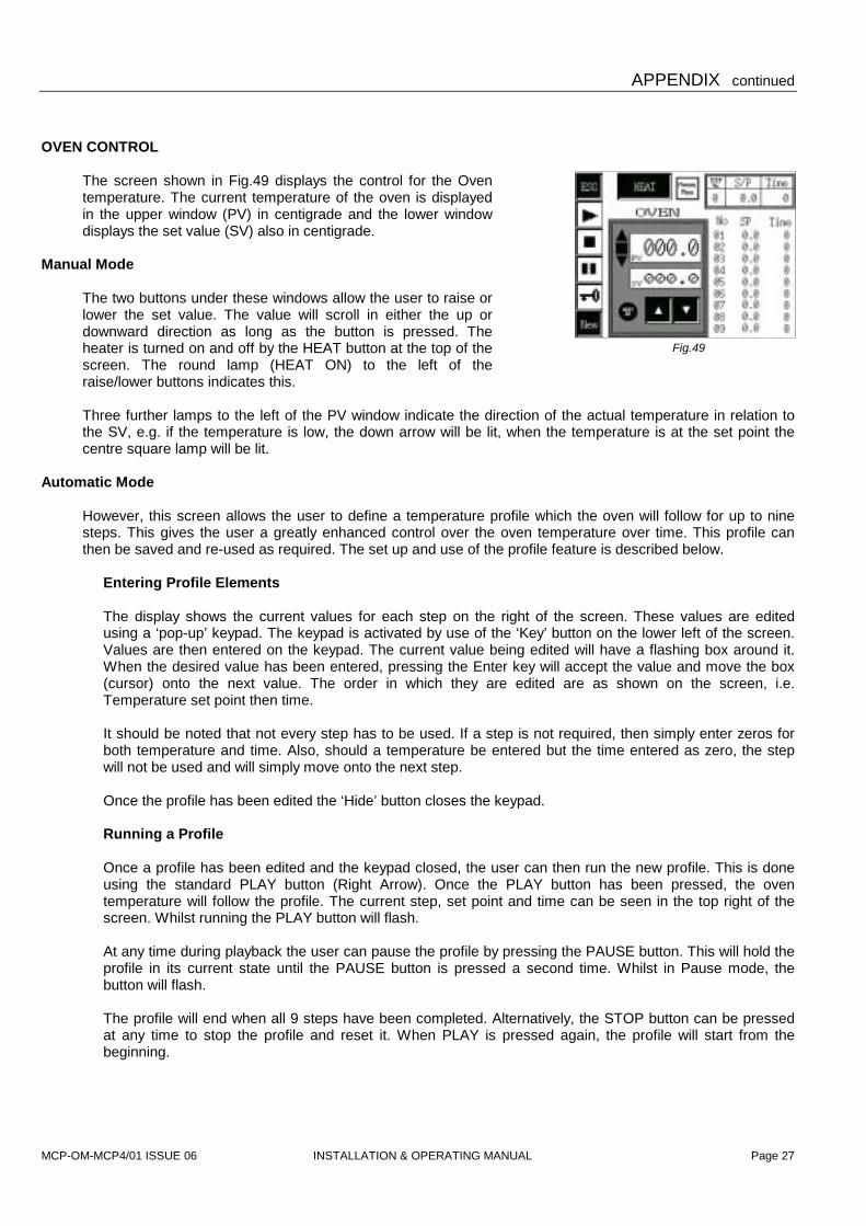
OVEN CONTROL
The screen shown in Fig.49 displays the control for the Oven temperature. The current temperature of the oven is displayed in the upper window (PV) in centigrade and the lower window displays the set value (SV) also in centigrade.
Manual Mode
The two buttons under these windows allow the user to raise or lower the set value. The value will scroll in either the up or downward direction as long as the button is pressed. The heater is turned on and off by the HEAT button at the top of the screen. The round lamp (HEAT ON) to the left of the raise/lower buttons indicates this. Three further lamps to the left of the PV window indicate the direction of the actual temperature in relation to the SV, e.g. if the temperature is low, the down arrow will be lit, when the temperature is at the set point the centre square lamp will be lit.
Automatic Mode
However, this screen allows the user to define a temperature profile which the oven will follow for up to nine steps. This gives the user a greatly enhanced control over the oven temperature over time. This profile can then be saved and re-used as required. The set up and use of the profile feature is described below.
Entering Profile Elements The display shows the current values for each step on the right of the screen. These values are edited using a ‘pop-up’ keypad. The keypad is activated by use of the ‘Key’ button on the lower left of the screen. Values are then entered on the keypad. The current value being edited will have a flashing box around it. When the desired value has been entered, pressing the Enter key will accept the value and move the box (cursor) onto the next value. The order in which they are edited are as shown on the screen, i.e. Temperature set point then time. It should be noted that not every step has to be used. If a step is not required, then simply enter zeros for both temperature and time. Also, should a temperature be entered but the time entered as zero, the step will not be used and will simply move onto the next step. Once the profile has been edited the ‘Hide’ button closes the keypad. Running a Profile Once a profile has been edited and the keypad closed, the user can then run the new profile. This is done using the standard PLAY button (Right Arrow). Once the PLAY button has been pressed, the oven temperature will follow the profile. The current step, set point and time can be seen in the top right of the screen. Whilst running the PLAY button will flash. At any time during playback the user can pause the profile by pressing the PAUSE button. This will hold the profile in its current state until the PAUSE button is pressed a second time. Whilst in Pause mode, the button will flash. The profile will end when all 9 steps have been completed. Alternatively, the STOP button can be pressed at any time to stop the profile and reset it. When PLAY is pressed again, the profile will start from the beginning.

MCP-OM-MCP4/01 ISSUE 06 INSTALLATION & OPERATING MANUAL Page 28
APPENDIX continued
Saving a Profile When a profile has been edited and checked to be correct, the user can save the current profile for use again. This is done using the NEW button. This takes the user to another screen asking if they wish to save or not. Pressing YES saves the profile details to memory and takes the user back to the previous screen. Pressing NO takes the user back to the previous screen without saving.
Pressing the ESC button takes the user back to the Heated Cup/Oven Menu screen.

MCP-OM-MCP4/01 ISSUE 06
ROUTINE MAINTENANCE PROCEDURES
* Before cidle for a
* Never us
* Check thafter obs
OIL CHANGES
The first oil change The period betweeweek of forty hocorresponding to 5any doubt). Longelife of the pump by A copy of the pumthe following instrube consulted for ex
1. Remove 2. Open the
and allosuitable r
3. When t
operate seconds
4. Close th
clean vaNOTE: Tinserted upper elfiller cap.
5. Close th
residual d
6. Repeat o
7. Close thReplace
Apart from keeping the unit in a generally clean condition, routine maintenance of the Vacuum Casting Machine is concerned with the vacuum pump and its associated filters. Users are referred to the Service Manual for other repair or replacement procedures.
INSTALLATION & OPERATING MANUAL Page 29
arrying out any operation on the vacuum pump or its filters, allow the equipment to stand t least one hour.
e any oil but the correct grade as recommended.
e oil level regularly. The optimal frequency depends greatly on usage and should be set ervation at short intervals (e.g. daily or weekly) during the first periods of use.
for a new pump should be made after 150 hours of operation.
n subsequent changes may be varied to match actual usage. Assuming a full working urs, MCP Equipment suggest that the oil be changed at intervals of three months, 00 hours (refer to the maintenance schedule in the pump manufacturer’s manual in case of r periods allow the build-up of sludge and other deleterious matter, which may shorten the causing excessive wear.
p manufacturer’s manual is supplied with the casting machine. For the user’s convenience, ctions summarise the procedure for maintenance of the pump, but the manual itself should plicit instructions for changes of oil and/or filter as well as other cleaning operations.
the oil filler cap from the top of the pump
drain tap at the bottom left of the pump w it to drain (through a hose) into a eceptacle.
he oil-flow appears to have ceased, the pump for no more than thirty with the vacuum chamber doors open.
e drain tap and put in one litre of fresh, cuum pump oil. Replace the filler plug. o fill with oil, use the supplied hose through the hole in the bottom of the ectrical compartment directly above the
e vacuum chamber doors and operate the pump for three or four minutes, to flush out eposits.
perations 1, 2 and 3.
e drain tap and refill the pump with fresh, clean oil to the gauge on the sight window. the oil filler cap.
Fig. 50

MCP-OM-MCP4/01 ISSUE 06 INSTALLATION & OPERATING MANUAL Page 30
ROUTINE MAINTENANCE continued
Operating the machine in very humid conditions can cause moisture to be drawn into the vacuum pump, where it will form a layer of water at the bottom of the sump and cause the level to rise about the gauge line. If you notice this effect (which is most easily discernible after a period of non-use, such as over a night), drain off the layer through the drain tape to bring the oil down to its correct level.

MCP-OM-MCP4/01 ISSUE 06 INSTALLATION & OPERATING MANUAL Page 31
DECLARATION OF CONFORMITY
Manufacturer’s name and address: MCP EQUIPMENT (A DIVISION OF MINING & CHEMICAL PRODUCTS LTD.) UNIT 8, WHITEBRIDGE INDUSTRIAL ESTATE, STONE STAFFORDSHIRE ST15 8LQ Equipment type and designation: Vacuum Casting Machine Type MCP 4/01 and variants Serial Number: ………………………………………………… Directives/Regulations to which
the equipment conforms: 1. Council Directive 98/37/EEC and its amending directives, leading in the United Kingdom to The Supply of Machinery (Safety) Regulations (SI 1992 No. 3073) (as they apply to equipment with a moving part and intended for treating or moving material. 2.Council Directive 92/31/EEC and its amending directives, leading in the United Kingdom to The Electromagnetic Compatibility Regulations (SI 1992 No. 2372).
3. Council Directive 72/23/EEC and its amending directives, leading in the United Kingdom to The Low Voltage Electrical Equipment (Safety) Regulations (SI 1989 No. 728).
Safety standard to which the
equipment uses: BS 2771 : Part 1, as applicable to the electrical and electronic equipment of machines not portable by hand when working, used in industrial production and operated from a supply up to 1000 VAC. (equivalent to European standard EN 60 204). The equipment also complies with the essential Health and Safety requirements.
Person responsible for Technical File: Simon Scott, Manager for Technical Data – MCP Equipment Division