Operating Instructions Liquicap M FMI51, FMI52 FEI57C …H...
56
BA297F/00/en/12.05 71000300 Valid as of software version: FW: V01.00.00 HW: V01.00 Operating Instructions Liquicap M FMI51, FMI52 FEI57C PFM Capacitive Level Measurement
Transcript of Operating Instructions Liquicap M FMI51, FMI52 FEI57C …H...

BA297F/00/en/12.0571000300Valid as of software version:FW: V01.00.00HW: V01.00
Operating Instructions
Liquicap M FMI51, FMI52FEI57C PFMCapacitive Level Measurement

Brief overview Liquicap M FMI51, FMI52 - Level Measurement - PFM
2
Brief overviewFor quick and easy commissioning:
Safety instructionsExplanation of the warning symbols
You can find special instructions at the appropriate position in the chapter in question. The positions are indicated with the icons Warning #, Caution " and
Note !.
→ Page 6 ff.
Æ
InstallationHere you can find the steps for installing the device and the installation
conditions (such as the dimensions etc.).
→ Page 16 ff.
Æ
WiringThe device is delivered ready-wired as far as is possible. → Page 33 ff.
Æ
Display and operating elementsHere you can find an overview of the layout of the device's display and
operating elements.→ Page 38 ff.
Æ
CommissioningThe "Commissioning" section tells you how to switch on the device and check
the functions.→ Page 39 ff.
Æ
TroubleshootingIf faults and malfunctions occur during operation, use the checklist to find the
cause.Here you can find measures you can take yourself to rectify any errors that may
occur.
→ Page 43 ff.
Liquicap M FMI51, FMI52 - Level Measurement - PFM Brief overview
3
Brief operating instructions
L00-FMI5xxxx-16-00-00-en-001
! Note! These Operating Instructions describe how to install and commission the level transmitter. All functions that are needed for regular measuring tasks are taken into account.In addition, the silometer, for example, has many other functions for optimising the measuring point and converting the measured value which do not form part of these Operating Instructions.
An overview of the configuration options at the FEI57C electronic insert is provided on Page 38.
2 (+)
1 (–)
d2 d4(+) (–)
SilometerFMC672
FMC672
VH
V12
+
–
+–mA1
H
–
E
1000
00>6 m
<6 m
Probe
length
FEI57C
Yes
NoBuild up
- +
FEI57CPFM
>6 m>6 m
<6 m<6 m
Yes
NoBuild up Probe
length
FMC672
VH
V12
+
–
+–mA1
H
–
E
1000
00
4. Make settings
1. Install probe 2. Wiring
3. Switch on power supply

Brief overview Liquicap M FMI51, FMI52 - Level Measurement - PFM
4

Liquicap M FMI51, FMI52 - Level Measurement - PFM Table of contents
5
Table of contents
1 Safety instructions . . . . . . . . . . . . . . . . 61.1 Designated use . . . . . . . . . . . . . . . . . . . . . . . . . . . . 61.2 Installation, commissioning and operation . . . . . . . . 61.3 Operational safety . . . . . . . . . . . . . . . . . . . . . . . . . . 61.4 Notes on safety conventions and icons . . . . . . . . . . . 7
2 Identification . . . . . . . . . . . . . . . . . . . . 82.1 Device designation . . . . . . . . . . . . . . . . . . . . . . . . . 82.2 Scope of delivery . . . . . . . . . . . . . . . . . . . . . . . . . . 152.3 Certificates and approvals . . . . . . . . . . . . . . . . . . . 152.4 Registered trademarks . . . . . . . . . . . . . . . . . . . . . . 15
3 Installation . . . . . . . . . . . . . . . . . . . . . 163.1 Quick installation guide . . . . . . . . . . . . . . . . . . . . . 163.2 Incoming acceptance, transport, storage . . . . . . . . . 163.3 Installation conditions . . . . . . . . . . . . . . . . . . . . . . 173.4 Installation instructions . . . . . . . . . . . . . . . . . . . . . 243.5 Installation examples . . . . . . . . . . . . . . . . . . . . . . . 253.6 With Separate Housing . . . . . . . . . . . . . . . . . . . . . 303.7 Post-installation check . . . . . . . . . . . . . . . . . . . . . . 32
4 Wiring . . . . . . . . . . . . . . . . . . . . . . . . 334.1 Quick wiring guide . . . . . . . . . . . . . . . . . . . . . . . . 334.2 Connecting the measuring unit . . . . . . . . . . . . . . . 354.3 Recommendations for connection . . . . . . . . . . . . . 374.4 Degree of protection . . . . . . . . . . . . . . . . . . . . . . . 374.5 Post-connection check . . . . . . . . . . . . . . . . . . . . . . 37
5 Operation . . . . . . . . . . . . . . . . . . . . . . 385.1 Quick operation guide . . . . . . . . . . . . . . . . . . . . . . 385.2 Display and operating elements . . . . . . . . . . . . . . . 385.3 Error messages . . . . . . . . . . . . . . . . . . . . . . . . . . . 38
6 Commissioning. . . . . . . . . . . . . . . . . . 396.1 Function check . . . . . . . . . . . . . . . . . . . . . . . . . . . 396.2 Transmitter . . . . . . . . . . . . . . . . . . . . . . . . . . . . . . 39
7 Maintenance. . . . . . . . . . . . . . . . . . . . 40
8 Accessories. . . . . . . . . . . . . . . . . . . . . 418.1 Protective cover . . . . . . . . . . . . . . . . . . . . . . . . . . 418.2 Shortening set . . . . . . . . . . . . . . . . . . . . . . . . . . . . 418.3 HAW569 surge arrester . . . . . . . . . . . . . . . . . . . . . 418.4 Welding boss for universal adapter . . . . . . . . . . . . . 418.5 Welding neck G ¾ . . . . . . . . . . . . . . . . . . . . . . . . 428.6 Welding neck G 1 . . . . . . . . . . . . . . . . . . . . . . . . . 42
9 Troubleshooting . . . . . . . . . . . . . . . . . 439.1 Fault analysis . . . . . . . . . . . . . . . . . . . . . . . . . . . . 439.2 Application errors . . . . . . . . . . . . . . . . . . . . . . . . . 439.3 Spare parts . . . . . . . . . . . . . . . . . . . . . . . . . . . . . . 44
9.4 Return . . . . . . . . . . . . . . . . . . . . . . . . . . . . . . . . . . 459.5 Disposal . . . . . . . . . . . . . . . . . . . . . . . . . . . . . . . . . 459.6 Softwarehistorie . . . . . . . . . . . . . . . . . . . . . . . . . . . 459.7 Contact addresses at Endress+Hauser . . . . . . . . . . . 45
10 Technical data . . . . . . . . . . . . . . . . . . 46

Safety instructions Liquicap M FMI51, FMI52 - Level Measurement - PFM
6
1 Safety instructions
1.1 Designated useLiquicap M FMI51, FMI52 are compact, capacitance level transmitters for the continuous measurement of conductive liquids.
1.2 Installation, commissioning and operationLiquicap M is designed to meet state-of-the-art safety regulations and complies with the applicable requirements and EC Directives. If used improperly or other than intended, the device can, however, be a source of application-related danger, e.g. product overflow as a result of incorrect installation or configuration. For this reason, installation, electrical connection, commissioning,operation and maintenance of the measuring system must only be carried out by trained technical personnel authorised to perform such work by the owner-operator.The technical personnel must have read and understood these Operating Instructions and must follow the instructions they contain. The device may only be repaired or modified if expressly permitted in the Operating Instructions.
1.3 Operational safety
1.3.1 Ex areaWhen using the measuring system in Ex-areas, the appropriate national standards and regulations have to be observed. Separate Ex documentation, which constitutes an integral part of this documentation, is supplied with the device. The installation procedures, connection data and safety instructions it contains must be observed.
• Make sure that the technical staff has adequate training.• The special measuring and safety-related requirements for the measuring points must be
observed.

Liquicap M FMI51, FMI52 - Level Measurement - PFM Safety instructions
7
1.4 Notes on safety conventions and iconsTo highlight safety-related or alternative processes, we have designed the following safety instructions where every instruction is indicated by a corresponding pictogram.
Safety instructions
#Warning!Draws attention to activities or procedures that can result in serious injuries to persons, a safety risk or the destruction of the device if not carried out properly.
"Caution!Draws attention to activities or procedures that can result in injuries to persons or the defective operation of the device if not carried out properly.
!Note!Draws attention to activities or procedures that have an indirect effect on operation, or can trigger an unforeseen device reaction if not carried out properly.
Type of protection
0Explosion-protected equipment tested for type examinationIf this sign can be found on the nameplate of the device, the device can be operated in hazardous areas or non-hazardous areas in accordance with the approval
-Hazardous areaThis symbol in the drawings in these Operating Instructions indicates Ex-areas. Devices located in Ex-areas, or cables for such devices, must have appropriate explosion protection.
.Safe area (non-hazardous area)This symbol in the drawings in these Operating Instructions indicates non-Ex areas. Devices in non-hazardous areas must also be certified if connecting cables lead into hazardous areas.
Electrical symbols
% Direct currentA terminal to which direct voltage is applied or through which the direct current flows.
&Alternating currentA terminal to which alternating voltage (sine wave) is applied or through which the alternating current flows.
) Ground connectionA grounded terminal which, from a user's point of view, is grounded via a grounding system.
* Protective earth connectionA terminal that has to be grounded before any other connections may be established.
+Equipotential connectionA connection that has to be connected to the grounding system of the plant. This can be a potential matching line or a star grounding system, depending on national or company codes of practice.
Immunity to temperature change of the connecting cablesMeans that the connecting cables have to withstand a temperature of 85 °C at least.t >85°C

Identification Liquicap M FMI51, FMI52 - Level Measurement - PFM
8
2 Identification
2.1 Device designation
2.1.1 NameplateYou can take the following technical data from the nameplate of the device:
L00-FMI5xxxx-18-00-00-en-001
Information on the nameplate of Liquicap M (example)
250002075 - -
Dat.:
IP66/ IP67NEMA4X
MWP:≤ Ta ≤ +60°C-40°C
Liquicap MOrder Code.:Ser.No.:
XA327F
BVS 05 ATEX E 103 X
ATEX II 1/2 G EEx ia IIB T6ATEX II 1/2 G EEx ia IIC T6
L1 = 1000L3 = 1000L = 2000
07/05
Made in Germany, D- 79689 Maulburg
Output:
XXXXXXXXXXXXXmmmmmm
FEI57C
FMI51-xxxxxxxxxxxxxx
U: 14,8 V DC
25bar
Z 65.13.xxx
PFM
Order number(see ordering information)
Approval No.
ATEX
Safety information
Serial number
Ambient temperature
at housing
Electronic insert
WHG approval
(German Water Resources Act)
Max. permissible pressure
in tank

Liquicap M FMI51, FMI52 - Level Measurement - PFM Identification
9
2.1.2 Liquicap M FMI51
10 Approval:A Non-hazardous areaB Non-hazardous area, WHG (German Water Resources Act)C ATEX II 1/2 GD EEx ia IIC T6D ATEX II 1/2 GD EEx ia IIC T6, WHG (German Water Resources Act)E ATEX II 1/2 GD EEx ia IIB T6F ATEX II 1/2 GD EEx ia IIB T6, WHG (German Water Resources Act)G ATEX II 1/2 G EEx d (ia) IIB T6, WHG (German Water Resources Act)H ATEX II 1/2 GD EEx ia IIC T6,
XA, observe safety instructions (electrostatic charge)!J ATEX II 1/2 GD EEx ia IIC T6, WHG (German Water Resources Act)
XA, observe safety instructions (electrostatic charge)!K ATEX II 1/2 G EEx ia IIC T6, WHG (German Water Resources Act)
XA, observe safety instructions (electrostatic charge)!L ATEX II 1/2 G EEx d (ia) IIC T6, WHG (German Water Resources Act)
XA, observe safety instructions (electrostatic charge)!M ATEX II 3 GD EEx nA II T6, WHG (German Water Resources Act)
XA, observe safety instructions (electrostatic charge)!N CSA General Purpose, C US CSAP CSA/FM IS Cl. I, II, III Div. 1+2 Gr. A-GR CSA/FM XP Cl. I, II, III Div. 1+2 Gr. A-GS TIIS Ex ia IIC T3T TIIS Ex d IIC T3Y Special version, to be specified
20 Inactive length (L3):Price per 100 mm/1 inchL3: 100...2000 mm/4...80 inch for 316LL3: 150...1000 mm/6...40 inch for PTFE fully insulatedProtection against condensate + bypassing container nozzles1 Not selected2 mm L3, 316L3 mm L3, 316L + PTFE fully insulated5 inch L3, 316L6 inch L3, 316L + PTFE fully insulated9 Special version, to be specified
30 Active probe length (L1); insulation:Price per 100 mm/1 inchL1: 100...4000 mm/4...160 inch for ∅10 mm, ∅16 mmL1: 150...3000 mm/6...120 inch for ∅22 mm (fully insulated)A mm L1, 10 mm, 316L; PTFEB mm L1, 16 mm, 316L; PTFEC mm L1, 22 mm, 316L; PTFED mm L1, 16 mm, 316L; PFAE mm L1, 10 mm, 316L; PTFE + ground tubeF mm L1, 16 mm, 316L; PTFE + ground tubeG mm L1, 16 mm, 316L; PFA + ground tubeH inch L1, 0.4 inch, 316L; PTFEK inch L1, 0.6 inch, 316L; PTFEM inch L1, 0.9 inch, 316L; PTFEN inch L1, 0.6 inch, 316L; PFAP inch L1, 0.4 inch, 316L; PTFE + ground tubeR inch L1, 0.6 inch, 316L; PTFE + ground tubeS inch L1, 0.6 inch, 316L; PFA + ground tubeY Special version, to be specified
50 Process connection:Threaded connectionGCJ G ½, 316L, 25 bar Thread ISO228 GDJ G ¾, 316L, 25 bar Thread ISO228 GEJ G 1, 316L, 25 bar Thread ISO228 GGJ G 1½, 316L, 100 bar Thread ISO228 RCJ NPT ½, 316L, 25 bar Thread ANSI RDJ NPT ¾, 316L, 25 bar Thread ANSI

Identification Liquicap M FMI51, FMI52 - Level Measurement - PFM
10
REJ NPT 1, 316L, 25 bar Thread ANSI RGJ NPT 1½, 316L, 100 bar Thread ANSI
Hygiene connectionGQJ G ¾ 316L, 25 bar Thread ISO2852
Accessories installation, welding neckGWJ G 1 316L, 25 bar Thread ISO2852
Accessories installation, welding neckMRJ DN50 PN40, 316L DIN11851UPJ Adapter 43 mm 316L, 25 bar
Tri-Clamp connectionTCJ DN25 (1"), EHEDG 316L, 25 bar Tri-Clamp ISO2852 TJJ DN38 (1½"), EHEDG 316L, 25 bar Tri-Clamp ISO2852 TDJ DN40-51 (2"), 316L, 100 bar Tri-Clamp ISO2852 TNJ DN38 (1½"), 316L, 25 bar, 3A Tri-Clamp ISO2852
Tri-Clamp, removable
EN flangesB0J DN25 PN25/40 A, 316L Flange EN1092-1 (DIN2527 B)B1J DN32 PN25/40 A, 316L Flange EN1092-1 (DIN2527 B)B2J DN40 PN25/40 A, 316L Flange EN1092-1 (DIN2527 B)B3J DN50 PN25/40 A, 316L Flange EN1092-1 (DIN2527 B)CRJ DN50 PN25/40 B1, 316L Flange EN1092-1 (DIN2527 C)DRJ DN50 PN40 C, 316L Flange EN1092-1 (DIN2512 F)ERJ DN50 PN40 D, 316L Flange EN1092-1 (DIN2512 N)BSJ DN80 PN10/16 A, 316L Flange EN1092-1 (DIN2527 B)CGJ DN80 PN10/16 B1, 316L Flange EN1092-1 (DIN2527 C)DGJ DN80 PN16 C, 316L Flange EN1092-1 (DIN2512 F)EGJ DN80 PN16 D, 316L Flange EN1092-1 (DIN2512 N)BTJ DN100 PN10/16 A, 316L Flange EN1092-1 (DIN2527 B)CHJ DN100 PN10/16 B1, 316L Flange EN1092-1 (DIN2527 C)
PTFE cladB0K DN25 PN25/40, PTFE >316L Flange EN1092-1 (DIN2527)B1K DN32 PN25/40, PTFE >316L Flange EN1092-1 (DIN2527)B2K DN40 PN25/40, PTFE >316L Flange EN1092-1 (DIN2527)B3K DN50 PN25/40, PTFE >316L Flange EN1092-1 (DIN2527)BSK DN80 PN10/16, PTFE >316L Flange EN1092-1 (DIN2527)BTK DN100 PN10/16, PTFE >316L Flange EN1092-1 (DIN2527)
ANSI flangesACJ 1" 150 lbs RF, 316/316L Flange ANSI B16.5ANJ 1" 300 lbs RF, 316/316L Flange ANSI B16.5AEJ 1½" 150 lbs RF, 316/316L Flange ANSI B16.5AQJ 1½" 300 lbs RF, 316/316L Flange ANSI B16.5AFJ 2" 150 lbs RF, 316/316L Flange ANSI B16.5ARJ 2" 300 lbs RF, 316/316L Flange ANSI B16.5AGJ 3" 150 lbs RF, 316/316L Flange ANSI B16.5ASJ 3" 300 lbs RF, 316/316L Flange ANSI B16.5AHJ 4" 150 lbs RF, 316/316L Flange ANSI B16.5ATJ 4" 300 lbs RF, 316/316L Flange ANSI B16.5AJJ 6" 150 lbs RF, 316/316L Flange ANSI B16.5AUJ 6" 300 lbs RF, 316/316L Flange ANSI B16.5
PTFE cladACK 1" 150 lbs, PTFE >316/316L Flange ANSI B16.5ANK 1" 300 lbs, PTFE >316/316L Flange ANSI B16.5AEK 1½" 150 lbs, PTFE >316/316L Flange ANSI B16.5AQK 1½" 300 lbs, PTFE >316/316L Flange ANSI B16.5AFK 2" 150 lbs, PTFE >316/316L Flange ANSI B16.5ARK 2" 300 lbs, PTFE >316/316L Flange ANSI B16.5AGK 3" 150 lbs, PTFE >316/316L Flange ANSI B16.5AHK 4" 150 lbs, PTFE >316/316L Flange ANSI B16.5
JIS flangesKCJ 10K 25 RF, 316L Flange JIS B2220KEJ 10K 40 RF, 316L Flange JIS B2220
50 Process connection:

Liquicap M FMI51, FMI52 - Level Measurement - PFM Identification
11
KFJ 10K 50 RF, 316L Flange JIS B2220KGJ 10K 80 RF, 316L Flange JIS B2220KHJ 10K 100 RF, 316L Flange JIS B2220KRJ 20K 50 RF, 316L Flange JIS B2220
PTFE cladKCK 10K 25 RF, PTFE >316L Flange JIS B2220KEK 10K 40 RF, PTFE >316L Flange JIS B2220KFK 10K 50 RF, PTFE >316L Flange JIS B2220KGK 10K 80 RF, PTFE >316L Flange JIS B2220KHK 10K 100 RF, PTFE >316L Flange JIS B2220
YY9 Special version, to be specified
60 Electronics; output:A FEI50H; 4...20 mA HART + displayB FEI50H; 4...20 mA HARTC FEI57C; PFMV Without; Prepared for FEI5x + display, High cover, transparentW Without; Prepared for FEI5x, Flat coverY Special version, to be specified
70 Housing:1 F15 316L IP66, NEMA4X2 F16 polyester IP66, NEMA4X3 F17 aluminium IP66, NEMA4X4 F13 aluminium + gas-tight process seal IP66, NEMA4X5 T13 aluminium + gas-tight process seal
+ separate connection compartmentIP66, NEMA4X
9 Special version, to be specified
80 Cable entry:A M20 threaded jointB Thread G ½C Thread NPT ½D Thread NPT ¾E M12 connectorF 7/8" connectorY Special version, to be specified
90 Probe design:L4: 300...6000 mm/12...240 inch1 Compact2 2000 mm L4 cable > separate housing3 ....mm L4 cable > separate housing4 80 inch L4 cable > separate housing5 ....inch L4 cable > separate housing9 Special version, to be specified
100 Additional option:A Basic versionB LABS free C Metal probe rod surface refiningD EN10204-3.1 (316L wetted parts), Inspection certificateE EN10204-3.1 (316L wetted),
NACE MR0175Inspection certificate
F SIL2/IEC61508 declaration of conformityS GL marine approval Y Special version, to be specified
FMI51 Product designation
50 Process connection:
Identification Liquicap M FMI51, FMI52 - Level Measurement - PFM
12
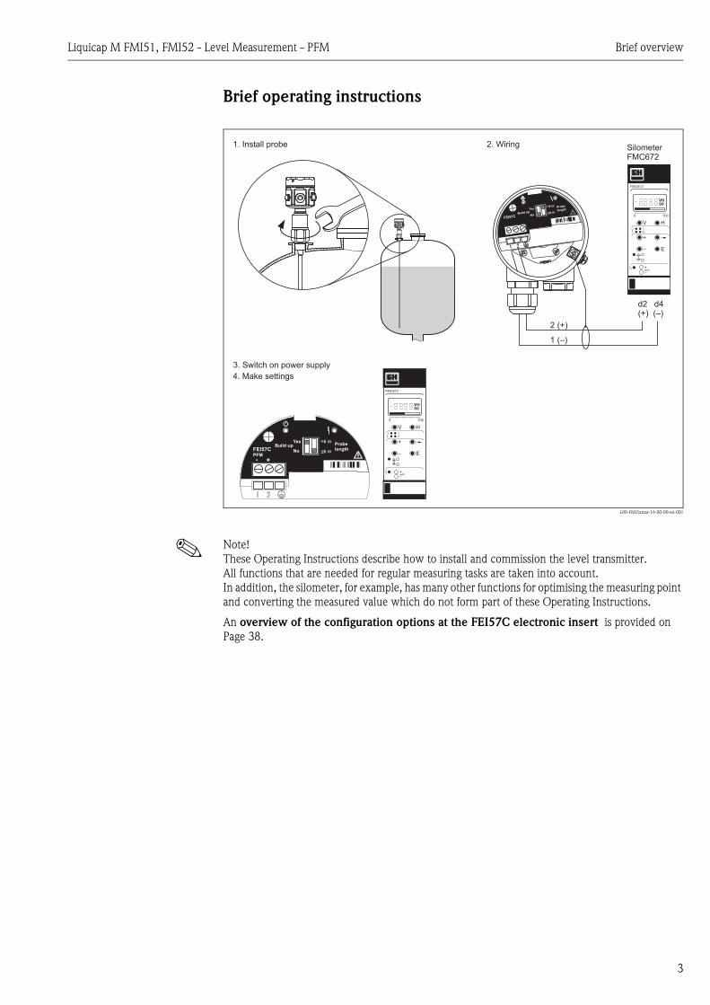
2.1.3 Liquicap M FMI52
10 Approval:A Non-hazardous areaB Non-hazardous area, WHG (German Water Resources Act)E ATEX II 1/2 GD EEx ia IIB T6F ATEX II 1/2 GD EEx ia IIB T6, WHG (German Water Resources Act)G ATEX II 1/2 G EEx d (ia) IIB T6, WHG (German Water Resources Act)H ATEX II 1/2 GD EEx ia IIC T6,
XA, observe safety instructions (electrostatic charge)!J ATEX II 1/2 GD EEx ia IIC T6,
XA, observe safety instructions (electrostatic charge)!K ATEX II 1/2 G EEx ia IIC T6, WHG (German Water Resources Act)
XA, observe safety instructions (electrostatic charge)!L ATEX II 1/2 G EEx d (ia) IIC T6, WHG (German Water Resources Act)
XA, observe safety instructions (electrostatic charge)!M ATEX II 3 GD EEx nA II T6, WHG (German Water Resources Act)
XA, observe safety instructions (electrostatic charge)!N CSA General Purpose, C US CSAP CSA/FM IS Cl. I, II, III Div. 1+2 Gr. A-GR CSA/FM XP Cl. I, II, III Div. 1+2 Gr. A-GS TIIS Ex ia IIC T3T TIIS Ex d IIC T3Y Special version, to be specified
20 Inactive length (L3):Price per 100 mm/1 inchL3: 100...2000 mm/4...80 inch for 316LL3: 150...1000 mm/6...40 inch for PTFE fully insulatedProtection against condensate + bypassing container nozzles1 Not selected2 ... mm L3, 316L3 ... mm L3, 316L + PFA fully insulated5 ... inch L3, 316L6 ... inch L3, 316L + PFA fully insulated9 Special version, to be specified
30 Active probe length (L1); insulation:Price per 1000 mm/10 inchL1: 420...10000 mm/17...400 inch; fully insulatedA ... mm L1, 316L; FEPB ... mm L1, 316L; PFAC ... inch L1, 316L; FEPD ... inch L1, 316L; PFAY Special version, to be specified
50 Process connection:Threaded connectionGDJ G ¾, 316L, 25 bar Thread ISO228 GEJ G 1, 316L, 25 bar Thread ISO228 GGJ G 1½, 316L, 100 bar Thread ISO228 RDJ NPT ¾, 316L, 25 bar Thread ANSI REJ NPT 1, 316L, 25 bar Thread ANSI RGJ NPT 1½, 316L, 100 bar Thread ANSI
Hygiene connectionGWJ G 1 316L, 25 bar Thread ISO2852
Accessories installation, welding neckMRJ DN50 PN40, 316L DIN11851UPJ Adapter 43 mm 316L, 25 bar
Tri-Clamp connectionTCJ DN25 (1"), EHEDG 316L, 25 bar Tri-Clamp ISO2852 TJJ DN38 (1½"), EHEDG 316L, 25 bar Tri-Clamp ISO2852 TDJ DN40-51 (2"), 316L, 100 bar Tri-Clamp ISO2852
Liquicap M FMI51, FMI52 - Level Measurement - PFM Identification
13
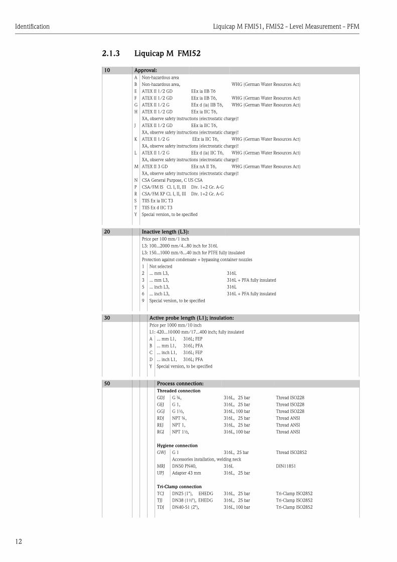
EN flangesB0J DN25 PN25/40 A, 316L Flange EN1092-1 (DIN2527 B)B1J DN32 PN25/40 A, 316L Flange EN1092-1 (DIN2527 B)B2J DN40 PN25/40 A, 316L Flange EN1092-1 (DIN2527 B)B3J DN50 PN25/40 A, 316L Flange EN1092-1 (DIN2527 B)CRJ DN50 PN25/40 B1, 316L Flange EN1092-1 (DIN2527 C)DRJ DN50 PN40 C, 316L Flange EN1092-1 (DIN2512 F)ERJ DN50 PN40 D, 316L Flange EN1092-1 (DIN2512 N)BSJ DN80 PN10/16 A, 316L Flange EN1092-1 (DIN2527 B)CGJ DN80 PN10/16 B1, 316L Flange EN1092-1 (DIN2527 C)DGJ DN80 PN16 C, 316L Flange EN1092-1 (DIN2512 F)EGJ DN80 PN16 D, 316L Flange EN1092-1 (DIN2512 N)BTJ DN100 PN10/16 A, 316L Flange EN1092-1 (DIN2527 B)CHJ DN100 PN10/16 B1, 316L Flange EN1092-1 (DIN2527 C)
PTFE cladB0K DN25 PN25/40, PTFE >316L Flange EN1092-1 (DIN2527)B1K DN32 PN25/40, PTFE >316L Flange EN1092-1 (DIN2527)B2K DN40 PN25/40, PTFE >316L Flange EN1092-1 (DIN2527)B3K DN50 PN25/40, PTFE >316L Flange EN1092-1 (DIN2527)BSK DN80 PN10/16, PTFE >316L Flange EN1092-1 (DIN2527)BTK DN100 PN10/16, PTFE >316L Flange EN1092-1 (DIN2527)
ANSI flangesACJ 1" 150 lbs RF, 316/316L Flange ANSI B16.5ANJ 1" 300 lbs RF, 316/316L Flange ANSI B16.5AEJ 1½" 150 lbs RF, 316/316L Flange ANSI B16.5AQJ 1½" 300 lbs RF, 316/316L Flange ANSI B16.5AFJ 2" 150 lbs RF, 316/316L Flange ANSI B16.5ARJ 2" 300 lbs RF, 316/316L Flange ANSI B16.5AGJ 3" 150 lbs RF, 316/316L Flange ANSI B16.5ASJ 3" 300 lbs RF, 316/316L Flange ANSI B16.5AHJ 4" 150 lbs RF, 316/316L Flange ANSI B16.5ATJ 4" 300 lbs RF, 316/316L Flange ANSI B16.5AJJ 6" 150 lbs RF, 316/316L Flange ANSI B16.5AUJ 6" 300 lbs RF, 316/316L Flange ANSI B16.5
PTFE cladACK 1" 150 lbs, PTFE >316/316L Flange ANSI B16.5ANK 1" 300 lbs, PTFE >316/316L Flange ANSI B16.5AEK 1½" 150 lbs, PTFE >316/316L Flange ANSI B16.5AQK 1½" 300 lbs, PTFE >316/316L Flange ANSI B16.5AFK 2" 150 lbs, PTFE >316/316L Flange ANSI B16.5ARK 2" 300 lbs, PTFE >316/316L Flange ANSI B16.5AGK 3" 150 lbs, PTFE >316/316L Flange ANSI B16.5AHK 4" 150 lbs, PTFE >316/316L Flange ANSI B16.5
JIS flangesKCJ 10K 25 RF, 316L Flange JIS B2220KEJ 10K 40 RF, 316L Flange JIS B2220KFJ 10K 50 RF, 316L Flange JIS B2220KGJ 10K 80 RF, 316L Flange JIS B2220KHJ 10K 100 RF, 316L Flange JIS B2220KRJ 20K 50 RF, 316L Flange JIS B2220
PTFE cladKCK 10K 25 RF, PTFE >316L Flange JIS B2220KEK 10K 40 RF, PTFE >316L Flange JIS B2220KFK 10K 50 RF, PTFE >316L Flange JIS B2220KGK 10K 80 RF, PTFE >316L Flange JIS B2220KHK 10K 100 RF, PTFE >316L Flange JIS B2220YY9 Special version, to be specified
60 Electronics; output:A FEI50H; 4...20 mA HART + displayB FEI50H; 4...20 mA HARTC FEI57C; PFMV Without; Prepared for FEI5x + display, High cover, transparent
50 Process connection:

Identification Liquicap M FMI51, FMI52 - Level Measurement - PFM
14
W Without; Prepared for FEI5x, Flat coverY Special version, to be specified
70 Housing:1 F15 316L IP66, NEMA4X2 F16 polyester IP66, NEMA4X3 F17 aluminium IP66, NEMA4X4 F13 aluminium + gas-tight process seal IP66, NEMA4X5 T13 aluminium + gas-tight process seal
+ separate connection compartmentIP66, NEMA4X
9 Special version, to be specified
80 Cable entry:A M20 threaded jointB Thread G ½C Thread NPT ½D Thread NPT ¾E M12 connectorF 7/8" connectorY Special version, to be specified
90 Probe design:L4: 100...6000 mm/12...240 inch1 Compact2 2000 mm L4 cable > separate housing3 ....mm L4 cable > separate housing4 80 inch L4 cable > separate housing5 ....inch L4 cable > separate housing9 Special version, to be specified
100 Additional Option:A Basic versionD EN10204-3.1 (316L wetted parts), Inspection certificateE EN10204-3.1 (316L wetted parts),
NACE MR0175Inspection certificate
F SIL2/IEC61508 declaration of conformityS GL marine approval Y Special version, to be specified
FMI52 Product designation
60 Electronics; output:

Liquicap M FMI51, FMI52 - Level Measurement - PFM Identification
15
2.2 Scope of delivery
" Caution! Please pay particular attention to the instructions on unpacking, transporting and storing the measuring devices outlined in the "Incoming acceptance, transport, storage" section on Page 16.
The scope of delivery comprises:• The installed device• Accessories, where applicable (see Page 41)
Documentation supplied:• Operating Instructions (this manual)• Approval documentation; if not listed in the Operating Instructions.
2.3 Certificates and approvalsCE mark, declaration of conformityThe device has been constructed and tested to state-of-the-art operational safety standards and left the factory in perfect condition as regards technical safety. The device complies with the applicable standards and regulations that are listed in the EC declaration of conformity and thus meets the legal requirements of the EC Directives. Endress+Hauser confirms that the device has been tested successfully by affixing the CE mark.
2.4 Registered trademarksKALREZ®, VITON®, TEFLON®
Registered trademarks of E.I. Du Pont de Nemours & Co., Wilmington, USA
Tri-Clamp® Registered trademark of Ladish & Co., Inc., Kenosha, USA
Installation Liquicap M FMI51, FMI52 - Level Measurement - PFM
16
3 Installation
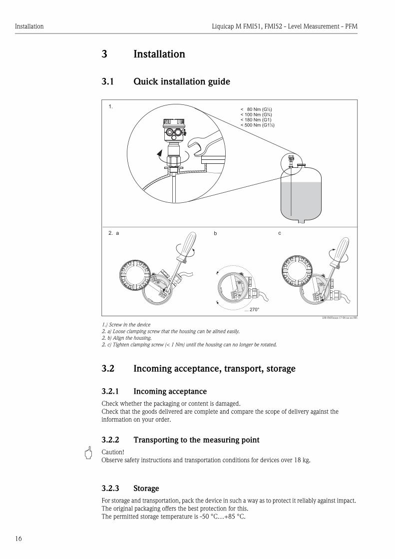
3.1 Quick installation guide
L00-FMI5xxxx-17-06-xx-xx-001
1.) Screw in the device2. a) Loose clamping screw that the housing can be alined easily.2. b) Align the housing.2. c) Tighten clamping screw (< 1 Nm) until the housing can no longer be rotated.
3.2 Incoming acceptance, transport, storage
3.2.1 Incoming acceptanceCheck whether the packaging or content is damaged.Check that the goods delivered are complete and compare the scope of delivery against the information on your order.
3.2.2 Transporting to the measuring point
" Caution! Observe safety instructions and transportation conditions for devices over 18 kg.
3.2.3 StorageFor storage and transportation, pack the device in such a way as to protect it reliably against impact. The original packaging offers the best protection for this.The permitted storage temperature is -50 °C…+85 °C.
12
a2.
1.
... 270°
b1
2
c
12
< 80 Nm (G )< 100 Nm (G )< 180 Nm (G1)< 500 Nm (G1 )
½
¾
½

Liquicap M FMI51, FMI52 - Level Measurement - PFM Installation
17
3.3 Installation conditions
L00-FMI5xxxx-03-05-xx-en-001
Po
lye
ste
rh
ou
sin
gF
16
Alu
min
ium
ho
usin
gF
17
Sta
inle
ss
ste
elh
ou
sin
gF
15
Alu
min
ium
T1
3h
ou
sin
g
with
asepara
teconnection
com
part
ment
and
gas-t
igh
tpro
cess
seal
Alu
min
ium
F1
3h
ou
sin
g
with
ag
as-t
igh
tp
roce
ss
se
al
Ro
d/r
op
ep
rob
e
10
mm
Ro
d/r
op
ep
rob
e
16
mm
Ro
d/r
op
ep
rob
ew
ith
ina
ctive
len
gth
10
mm
Ro
d/r
op
ep
rob
ew
ith
ina
ctive
len
gth
16
mm
Fu
llyin
su
late
dro
d/r
op
ep
rob
ew
ith
fully
insu
late
din
active
len
gth
22
mm
Tri-C
lam
p(D
N3
8(1
½")
;D
N4
0-5
1(2
"))
Cla
dfla
ng
es
(EN
,A
NS
I,JIS
)H
ose
gla
nd
(DN
50
PN
40
)
Th
rea
d(G
¾,
NP
T¾
;G
1,
NP
T1
;G
1½
,N
PT
1½
)
Fla
ng
es
(EN
,A
NS
I,JIS
)
Tri-C
lam
p(D
N2
5(1
");
DN
38
(1½
"))
Hyg
ien
e(G
¾,
G1
)
Ho
se
gla
nd
(DN
50
PN
40
)
Th
rea
d(G
½,
NP
T½
;G
¾,
NP
T¾
;G
1,
NP
T1
)
Fla
ng
es
(EN
,A
NS
I,JIS
)
Ele
ctr
on
ics
Dis
pla
y
Dis
pla
yh
old
er
Hyg
ien
e(u
niv
ers
ala
da
pte
r)
Hyg
ien
eco
nn
ectio
ns
Flu
sh
-mo
un
ted
se
al
Hyg
ien
eco
nn
ectio
ns

Installation Liquicap M FMI51, FMI52 - Level Measurement - PFM
18
3.3.1 Housing
! Note! High cover for housing with display. All dimensions in mm (100 mm = 3.94 in).
Polyester housing F16
L00-FMI5xxxx-06-05-xx-en-001
Stainless steel housing F15
L00-FMI5xxxx-06-05-xx-en-003
Aluminium housing F17
L00-FMI5xxxx-06-05-xx-en-002
Aluminium housing F13with gas-tight process seal
L00-FMI5xxxx-06-05-xx-en-000
Aluminium housing T13with separate connection compartment and gas-tight process seal
L00-FMI5xxxx-06-05-xx-en-004
ø85 max. 76
ap
pro
x.
97
ap
pro
x.
11
6
ø76 max. 64
appr
ox.9
5
appr
ox.1
34
ø80 max. 60
max. 65
ap
pro
x.1
05
ap
pro
x.1
34
ø80 max. 60
max. 65
appro
x.118
appro
x.147
max. 65 max. 97
appro
x.135
appro
x.147

Liquicap M FMI51, FMI52 - Level Measurement - PFM Installation
19
3.3.2 Housing extension heights with adapter
3.3.3 Process connections
Polyester housingF16
Stainless steel housingF15
Aluminium housingF17
Aluminium housingF13*
Aluminium housing with separate connection compartment T13*
L00-FMI5xxxx-06-05-xx-xx-044 L00-FMI5xxxx-06-05-xx-xx-046 L00-FMI5xxxx-06-05-xx-xx-045 L00-FMI5xxxx-06-05-xx-xx-048 L00-FMI5xxxx-06-05-xx-xx-047
Order code 2 1 3 4 5
FMI51, FMI52
H1 (for electronic inserts without display)
144 142 152 194 202
H2 (for electronic inserts with display)
163 181 181 223 214
* Housing with gas-tight process seal
H1H2
H1H
2
H1H2
H1H
2
H1H2
Thread G Thread NPT Threaded pipe joint Tri-Clamp
L00-FMI5xxxx-06-05-xx-en-007
(DIN ISO228/I)
L00-FMI5xxxx-06-05-xx-en-008
(ANSI B 1.20.1)
L00-FMI5xxxx-06-05-xx-xx-040
(DIN11851)
L00-FMI5xxxx-06-05-xx-xx-041
(ISO2852)
Rod probes ∅∅∅∅10, rope probes
For pressures up to 25 bar 25 bar 25 bar 16 bar
Version / order code G½ / GCJG¾ / GDJG1 / GEJ
NPT½ / RCJNPT¾ / RDJNPT1 / REJ
DN50 PN40 / MRJ DN25 (1") / TCJDN38 (1½") / TJJ
Dimensions H1 = 38H2 = 19AF = 41
H1 = 38H2 = 19AF = 41
H1 = 57 H1 = 57
Surface roughness - - ≤ 0.8 µm ≤ 0.8 µm
Additional information With elastomer flat seal - - EHEDG
Rod probes ∅∅∅∅16, rope probes
For pressures up to 25 bar 100 bar 25 bar 100 bar 40 bar 16 bar 16 bar
Version / order code G¾ / GDJG1 / GEJ
G1½ / GGJ NPT¾ / RDJNPT1 / REJ
NPT1½ / RGJ DN50 PN40 / MRJ DN38 / TJJ(1½")
DN40-51 / TDJ (2")
Dimensions H1 = 38H2 = 19AF = 41
H1 = 41H2 = 25AF = 55
H1 = 38H2 = 19AF = 41
H1 = 41H2 = 25AF = 55
H1 = 66 H1 = 47 H1 = 66
Surface roughness - - ≤ 0.8 µm ≤ 0.8 µm ≤ 0.8 µm
Additional information With elastomer flat seal - - -
H1
H2
AF
H1
H2
AF
H1
H1

Installation Liquicap M FMI51, FMI52 - Level Measurement - PFM
20
! Note! Only use clad flanges for aggressive liquids.
Rod probes ∅∅∅∅22, rope probes
For pressures up to 50 bar 50 bar - -
Version / order code G1½ / GGJ NPT1½ / RGJ - -
Dimensions H1 = 85H2 = 25AF = 55
H1 = 85H2 = 25AF = 55
- -
Surface roughness - - ≤ 0.8 µm ≤ 0.8 µm
Additional information With elastomer flat seal - - -
Thread G Thread NPT Threaded pipe joint Tri-Clamp
Flanges Hygiene connection Hygiene connection Hygiene connection
L00-FMI5xxxx-06-05-xx-xx-042
(EN1092-1)(ANSI B 16.5)(JIS B2220)
L00-FMI5xxxx-06-05-xx-en-009
With flush-mounted seal
L00-FMI5xxxx-06-05-xx-en-010
With flush-mounted seal
L00-FMI5xxxx-06-05-xx-xx-043
Adapter 43 mm with flush-mounted seal
Rod probes ∅∅∅∅10, rope probes
For pressures up to max. 25 bar (depends on flange) 25 bar 25 bar -
Version / order code EN / B**ANSI / A**JIS / K**
G¾ / GQJ G1 / GWJ -
Dimensions H1 = 57 H1 = 31H2 = 26AF = 41
H1 = 30H2 = 27AF = 41
-
Additional information Also clad (PTFE) Welding neck see "Accessories" Page 42
Welding neck see "Accessories" Page 42
-
Rod probes ∅∅∅∅16, rope probes
For pressures up to max. 100 bar (depends on flange) - - 16 bar(tightening torque 10 Nm)
Version / order code EN / B**ANSI / A**JIS / K**
- - Universal adapter
Dimensions H1 = 66 - - H1 = 57
Additional information Also clad (PTFE) - - Universal adapter see "Accessories" Page 41
Rod probes ∅∅∅∅22, rope probes
For pressures up to max. 50 bar (depends on flange) - - -
Version / order code EN / B**ANSI / A**JIS / K**
- - -
Dimensions H1 = 110 - - -
Additional information Only clad (PTFE) - - -
** Wildcard for nominal diameter and permitted process pressure
H1
H1
H2
AF
H1
H2
AF
H1

Liquicap M FMI51, FMI52 - Level Measurement - PFM Installation
21
3.3.4 Rod probes FMI51
! Note! • The active probe rod is always fully insulated (dimension L1).• Total length of probe from sealing surface: L = L1 + L3• For conductive liquids (> 100 µS/cm), the probe is already calibrated at the factory to the probe
length ordered (0 %...100 %). For non-conductive liquids (< 100 µS/cm), 0 %-calibration is performed at the factory. Only the 100 % calibration has to be carried out on site.
Probe lengths
Rod probe Rod probe with ground tube
Rod probe with inactive length
Rod probe with inactive length and ground tube
Rod probe with fully insulated inactive length
L00-FMI5xxxx-06-05-xx-xx-031 L00-FMI5xxxx-06-05-xx-xx-032 L00-FMI5xxxx-06-05-xx-xx-033 L00-FMI5xxxx-06-05-xx-xx-035 L00-FMI5xxxx-06-05-xx-xx-034
Probe rod diameter 10 / 16 10 / 16 10 / 16 10 / 16 22
Diameter of ground tube with or without inactive length
- / - 22 / 43 22 / 43 22 / 43 22
Lateral loading capacity (Nm) at 20 °C < 15 / < 30 < 40 /< 300 < 30 /< 60 < 40 /< 300 < 25
For use in agitating tanks - - / X - - / X -
For conductive liquids > 100 µS/cm
X - X - X
For non-conductive liquids< 100 µS/cm
- X - X -
For aggressive liquids X - - - X
For high-viscosity liquids X - X - X
For use in plastic tanks - X - X -
For use in mounting nozzles - - X X X
In the event of condensate on tank ceiling
- - X X X
X = suggested
L1 L1
NPT GL
1 L1
NPT G
L3
L1
L3
L1
NPT G
L3
L1
L3
L1
NPT G
L3
L1
L3
L1
NPT G
Active rod length (L1) Inactive rod length (L3) Total length (L)
Length (with ∅10) 100...4000 100...2000 100...6000
Length (with ∅16) 100...4000 100...2000 100...6000
Length (with ∅22) 150...3000 150...1000 300...4000
Length toleranceUp to 1 m: 0...5 mm Up to 3 m: 0...10 mm Up to 6 m: 0...20 mm

Installation Liquicap M FMI51, FMI52 - Level Measurement - PFM
22
3.3.5 FMI52 rope probes
! Note! • The active probe length is always fully insulated (dimension L1).• Total length of probe from sealing surface: L = L1 + L3• All rope probes are prepared for tensioning in containers (tensioning weight with anchor hole)• For conductive liquids (> 100 µS/cm), the probe is already calibrated at the factory to the probe
length ordered (0 %...100 %). For non-conductive liquids (< 100 µS/cm), 0 %-calibration is performed at the factory. Only the 100 % calibration has to be carried out on site.
• Not siutable for agitating tanks, high-viscosity liquids and plastic tanks.
Rope probe lengths
Rope probe Rope probe with inactive length
Rope probe with fully insulated inactive length
L00-FMI5xxxx-06-05-xx-xx-036 L00-FMI5xxxx-06-05-xx-xx-037 L00-FMI5xxxx-06-05-xx-xx-039
Probe rope diameter 4 4 4
Diameter of anchor weight 22 22 22
Diameter of anchor hole 5 5 5
Tensile loading capacity (N) of probe rope at 20 °C
200 200 200
For conductive liquids > 100 µS/cm
X X X
For non-conductive liquids < 100 µS/cm
X X X
For aggressive liquids X - X
For use in mounting nozzles - X X
In the event of condensate on tank ceiling
- X X
X = suggested
L1
L1
NPTNPT GG
120
120
L1
L1
L1
L1
L3
L3
L1
L1
L3
L3
NPTNPT GG
120
120
L3
L3
120
120
L1
L1
L3
L3
L1
L1
NPTNPT GG
Active rope length (L1) Inactive length (L3) Total length (L)
Length (L3 fully insulated) 420...10000 150...1000 (fully insulated) 420...11000
Length (L3 uninsulated) 420...10000 100...2000 (uninsulated, 316L) 420...12000
Length toleranceUp to 1 m: 0...10 mm Up to 3 m: 0...20 mm Up to 6 m: 0...30 mm Up to 12 m: 0...40 mm
Liquicap M FMI51, FMI52 - Level Measurement - PFM Installation
23
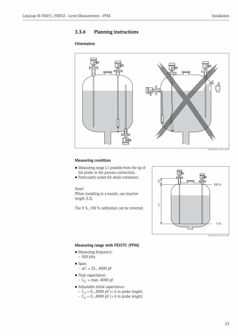
3.3.6 Planning instructions
Orientation
L00-FMI5xxxx-11-06-xx-xx-003
Measuring condition
Measuring range with FEI57C (PFM)
• Measuring frequency: – 500 kHz
• Span: – ∆C = 25...4000 pF
• Final capacitance: – CE = max. 4000 pF
• Adjustable initial capacitance: – CA = 0...2000 pF (< 6 m probe length)– CA = 0...4000 pF (> 6 m probe length)
• Measuring range L1 possible from the tip of the probe to the process connection.
• Particularly suited for small containers.
Note!When installing in a nozzle, use inactive length (L3).
The 0 %, 100 % calibration can be inverted.
L00-FMI5xxxx-15-05-xx-xx-002
100 %
0 %
L3
L1
Installation Liquicap M FMI51, FMI52 - Level Measurement - PFM
24
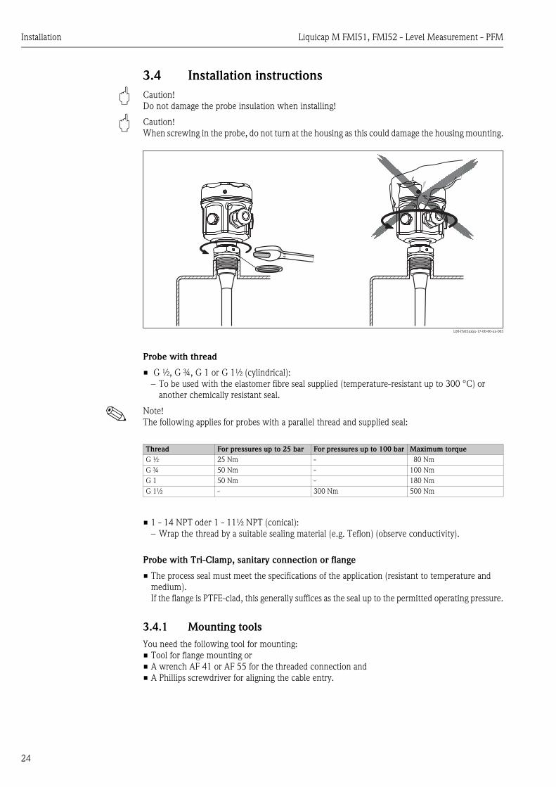
3.4 Installation instructions
" Caution! Do not damage the probe insulation when installing!
" Caution! When screwing in the probe, do not turn at the housing as this could damage the housing mounting.
L00-FMI5xxxx-17-00-00-xx-003
Probe with thread
• G ½, G ¾, G 1 or G 1½ (cylindrical): – To be used with the elastomer fibre seal supplied (temperature-resistant up to 300 °C) or
another chemically resistant seal.
! Note! The following applies for probes with a parallel thread and supplied seal:
• 1 - 14 NPT oder 1 - 11½ NPT (conical):– Wrap the thread by a suitable sealing material (e.g. Teflon) (observe conductivity).
Probe with Tri-Clamp, sanitary connection or flange
• The process seal must meet the specifications of the application (resistant to temperature and medium).If the flange is PTFE-clad, this generally suffices as the seal up to the permitted operating pressure.
3.4.1 Mounting toolsYou need the following tool for mounting:• Tool for flange mounting or• A wrench AF 41 or AF 55 for the threaded connection and• A Phillips screwdriver for aligning the cable entry.
41
Thread For pressures up to 25 bar For pressures up to 100 bar Maximum torqueG ½ 25 Nm - 80 NmG ¾ 50 Nm - 100 NmG 1 50 Nm - 180 NmG 1½ - 300 Nm 500 Nm

Liquicap M FMI51, FMI52 - Level Measurement - PFM Installation
25
3.5 Installation examples
3.5.1 Rod probes
Conductive tanks (metal tanks)
If the process connection of the probe is insulated from the metal tank (e.g. through seal material), the ground connection at the probe housing must be connected to the tank by means of a short cable.
! Note! A fully insulated rod probe may neither be shortened nor extended. If the insulation of the probe rod is damaged, this results in an incorrect measurement result.
FMI51 rod probe
L00-FMI5xxxx-11-06-xx-xx-004
FMI51 rod probe with ground tube
Non-conductive tanks (plastic tanks)
When installing in a plastic tank, a probe with a ground tube must be used.
L00-FMI5xxxx-11-06-xx-xx-005

Installation Liquicap M FMI51, FMI52 - Level Measurement - PFM
26
FMI51 rod probe with inactive length (e.g. for insulated tanks)
L00-FMI5xxxx-11-06-xx-xx-006
FMI51 rod probe with ground tube and inactive length (for mounting nozzles)
L00-FMI5xxxx-11-06-xx-xx-007
FMI51 fully insulated probe with clad flange for aggressive media
L00-FMI5xxxx-11-06-xx-xx-011

Liquicap M FMI51, FMI52 - Level Measurement - PFM Installation
27
3.5.2 Rope probes
FMI52 rope probe
L00-FMI5xxxx-11-06-xx-xx-008
FMI52 rope probe with inactive length (e.g. for insulated tanks)
L00-FMI5xxxx-11-06-xx-xx-009

Installation Liquicap M FMI51, FMI52 - Level Measurement - PFM
28
FMI52 rope probe with fully insulated inactive length (for mounting nozzles)
L00-FMI5xxxx-11-06-xx-xx-010
3.5.3 Shortening the rope
! Note! See Operating Instructions, rope shortening kit KA063F/00.
3.5.4 Tensioning weight with tensionThe end of the probe needs to be secured if the probe would otherwise touch the silo wall or another part in the tank. This is what the internal thread in the probe weight is intended for. The bracing can be coductive or insulating to the tank wall.
To avoid a to high tensile load the rope should be loose or guyed with a feather. The maximum tensile load may not exceed 200 Nm.
L00-FMI5xxxx-11-06-xx-xx-012

Liquicap M FMI51, FMI52 - Level Measurement - PFM Installation
29
3.5.5 Align the housingThe housing can be rotated 270° to align the cable entry. For an even better way of preventing moisture penetration, we recommend you route the connecting cable downwards before the cable gland and secure it with a cable tie. This is particularly recommended when mounting outdoors.
Housing (type F16, F15, F17, F13, T13)• Unscrew cover• Loosen Phillips screw at bottom of housing by turning the screw 3 to 4 times• Turn the housing to the desired position (max. 270°, from one stop to the next)• Tighten Phillips screw at bottom of housing.
! Note! For housing type T13 with a separate connection compartment, the Phillips screw for aligning the housing is also located in the electronics compartment.
L00-FMI5xxxx-04-00-00-xx-002
1. Loose clamping screw that the housing can be alined easily.2. Align the housing.3. Tighten clamping screw (< 1 Nm) until the housing can no longer be rotated.4. Additional protection against moisture penetration for electronics compartment.
3.5.6 Sealing the probe housingWhen mounting the probe, connecting the electronic insert and later during operation, it is important that moisture does not penetrate the probe housing. For this reason, the housing cover and the cable entries must always be closed tight.
The O-ring seal on the housing cover is provided with a lubricant when delivered. In this way, the cover can be sealed tight and the aluminium thread does not bite when screwing down. Never use a lubricant on a mineral-oil base! This would destroy the O-ring.
12
1.
... 270°
2.
12
3.
12
4.

Installation Liquicap M FMI51, FMI52 - Level Measurement - PFM
30
3.6 With Separate Housing
L00-FMI5xxxx-14-00-06-xx-002
Rod length L1 max. 4 m Rope length L1 max. 10 m
L00-FMI5xxxx-03-05-xx-en-005
EX
Zone 1*
L4 6 m
EX
Zone 0*
L1
GN/YEGN/YE
YEYE
RDRD1. Pressing screw1. Pressing screw
2. Insert seal2. Insert seal
3. Cabel gland3. Cabel gland
4. Heat4. Heatshrinking sleeveshrinking sleeve
5. Seal5. Seal
6.6. Adapter diskAdapter disk
7. Seal7. Seal
8. Plug M38. Plug M3
9. S9. Split washerplit washer10. S10. Strand yellow/greentrand yellow/green (YE/GN) with ring terminal(YE/GN) with ring terminal
111. S1. Strandtrand yellow (YE) with ring terminal andyellow (YE) with ring terminal andheatheatshringking sleeveshringking sleeve
12. Snap ring12. Snap ring13. Nut M413. Nut M414. S14. Split washerplit washer15. S15. Strand red (RD) with ring terminal andtrand red (RD) with ring terminal and
heatheatshringking sleeveshringking sleeve
16. Blade plug16. Blade plug
17.17. TTubeube
18. Process connection18. Process connection
20. S20. Strand black (BK)trand black (BK)(not required)(not required)
22. S22. Strand yellow/green (YE/GN)trand yellow/green (YE/GN)with a ring terminalwith a ring terminal
24. Solder the24. Solder the strandstrandwith the central core of thewith the central core of thecoaxial cablecoaxial cable
red (RD)red (RD)
23. Solder the23. Solder the strandstrandwith the screening of thewith the screening of the
yellow (YE)yellow (YE)
coaxial cablecoaxial cable
19. External screening19. External screening(not required)(not required)
21. Coaxial cable with21. Coaxial cable withndnd
central corecentral coreaa screeningscreening
Liquicap M FMI51, FMI52 - Level Measurement - PFM Installation
31
3.6.1 Shortening the Connecting Cable
! Note! The maximum connection length between the probe and the separate housing is 6 m and is shown by the dimension L4. When ordering a Liquicap M with separate housing you must indicate the required connection length.
If the connecting cable must be shortened or be led through a wall, you must disconnect the cable from the process connection. Please proceed as follows:
• Loosen the pressing screw (1) with an open-end wrench (size 22). If necessary, hold the process connection. Please make sure that neither the connecting cable nor the probe is turning with the pressing screw.
• Pull the insert seal (2) out of the cable gland (3).• Loosen the cable gland (3) with an open-end wrench (size 22). If necessary, hold the adapter disk
(6) with an open-end wrench (size 34).• Loosen the adapter disk (6) from the tube (17).• Remove the snap ring with a pair of snap ring pliers.• Clutch the nut (M4) of the blade plug with a pair of pliers and pull this out.
! Note! If you are shortening the connecting cable, we recommend to reuse all strands with ring terminals. After the strands were soldered on again the soldering points must be isolated.
! Note! If the strands are not reused, the ring terminals of the yellow and the red strand must be isolated at the crimp connection e.g. with a heat shrinking sleeve (Danger of short-circuit).
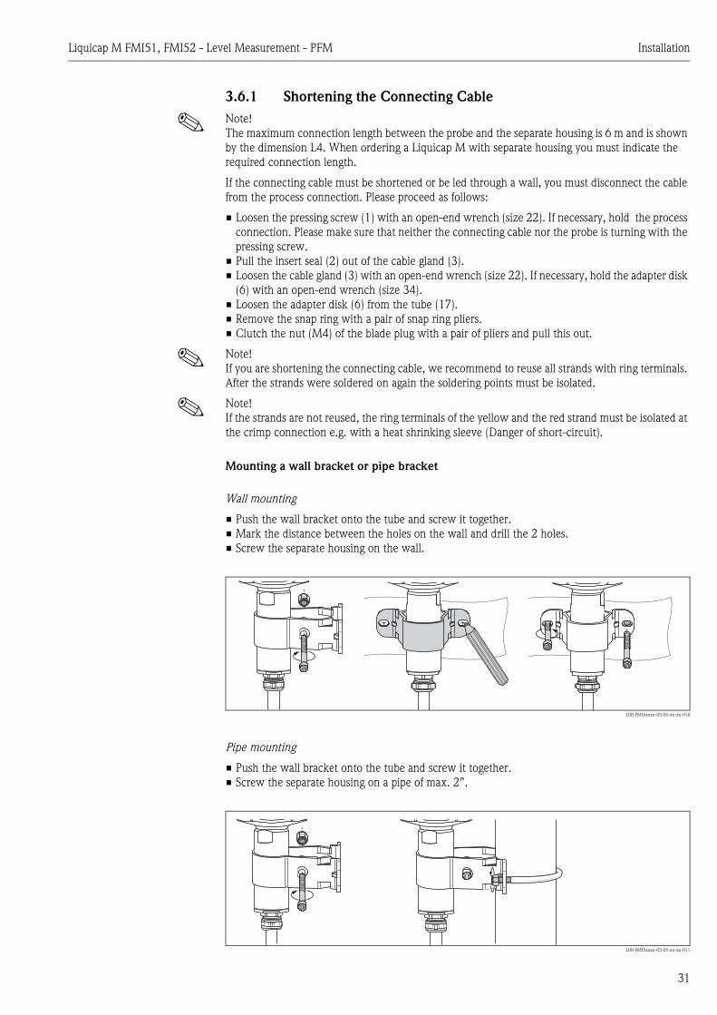
Mounting a wall bracket or pipe bracket
Wall mounting
• Push the wall bracket onto the tube and screw it together.• Mark the distance between the holes on the wall and drill the 2 holes.• Screw the separate housing on the wall.
L00-FMI5xxxx-03-05-xx-xx-010
Pipe mounting
• Push the wall bracket onto the tube and screw it together.• Screw the separate housing on a pipe of max. 2”.
L00-FMI5xxxx-03-05-xx-xx-011

Installation Liquicap M FMI51, FMI52 - Level Measurement - PFM
32
3.6.2 Process conditions
L00-FMI5xxxx-05-05-xx-xx-011
Ta = ambient temperatureTP = process temperature
3.7 Post-installation checkAfter installing the measuring device, carry out the following checks:• Is the device damaged (visual inspection)?• Does the device meet the specifications at the measuring point with regard to process
temperature/pressure, ambient temperature, measuring range etc.?• Has the process connection been tightened with the appropriate tightening torque?• Are the measuring point number and labelling correct (visual inspection)?• Is the device adequately protected against precipitation and direct sunshine?
Ta
0
0
TP
–40 –20–60 80 120 160 180
80
60
40
20
–80 200
–60
–40
–20
20 40 60 100 140
+200/+70
+120+120
/
°C
Ta
120
100
°C
TP

Liquicap M FMI51, FMI52 - Level Measurement - PFM Wiring
33
4 Wiring
4.1 Quick wiring guide
Wiring in F16, F15, F17, F13 housings
L00-FMI5xxxx-04-00-00-en-010
-
-
"
– +– +FEI57C
1 2
1
1 2– +
< 6 mProbelength
> 6 m
6
FMC672
VH
V12
+
–
+–mA1
H
–
E
1000
00
5
2
3
4
250002075 - -
Dat.:
IP66/ IP67NEMA4X
MWP:≤ Ta ≤ +60°C-40°C
Liquicap MOrder Code.:Ser.No.:
XA327F
L3 = 1000 mm
10/04
Made in Germany, D- 79689 Maulburg
Output:
XXXXXXXXXXXXXL1 = 1000 mm
FEI57C
FMI51-xxxxxxxxxxxxxx
U: 14,8 V DC
25bar
BVS 05 ATEX E 103 XATEX II 1/2 G EEx ia IIC T6ATEX II 1/2 G EEx ia IIB T6
Z 65.13.xxx
PFM
Yes
No
Build up
Before connecting, please note the following:
The supply voltage must match that on the nameplate (1).
Switch off the supply voltage before connecting the device.
Connect the potential matching line to the earth terminal ofthe sensor before connecting the device to the power supply.
When using the probe in hazardous areas, applicable national standards and the informationin the Safety Instructions (XA) must be observed. The specified cable gland must be used.
The explosion protection is as follows for devices with acertificate:
Housing F15, F16 - EEx ia:The power supply must be intrinsically safe.
Caution!
sealed connectioncompartment
PML
Liquicap M is connected as follows:
Remove the housing cover (2).
Guide the connecting cable (3) through the gland (4).
Ground the screening cable (5) on both sides!
Establish the connection (see terminal assignment).
Tighten the cable gland (4).
Make the appropriate settings at the electronic insert withregard to build-up and probe length (6).
Screw down the housing cover (2).
Switch on the power supply.
e.g. supply unitFMC672
d4 d2(–) (+)

Wiring Liquicap M FMI51, FMI52 - Level Measurement - PFM
34
Wiring in T13 housing
L00-FMI5xxxx-04-00-00-en-011
1
-
-
"
5
1 2– +
d4 d2(–) (+)
FMC672
VH
V12
+
–
+–mA1
H
–
E
1000
00
3
4
2
IS-
Gro
und
– +
1 2
IS-
Gro
und
– +
1 2
IS-
Gro
und
– +1 2
250002075 - -
Dat.:
IP66/ IP67NEMA4X
MWP:≤ Ta ≤ +60°C-40°C
Liquicap MOrder Code.:Ser.No.:
XA327F
L3 = 1000 mm
10/04
Made in Germany, D- 79689 Maulburg
Output:
XXXXXXXXXXXXXL1 = 1000 mm
FEI57C
FMI51-xxxxxxxxxxxxxx
U: 14,8 V DC
25bar
BVS 05 ATEX E 103 XATEX II 1/2 G EEx ia IIC T6ATEX II 1/2 G EEx ia IIB T6
Z 65.13.xxx
PFM
Liquicap M is connected as follows:
Switch off the power supply before the housing cover (2) is unscrewedat the separate connection compartment!
Pull the connecting cable (3) through the gland (4). Ground thescreening cable (5) on both sides!
Establish the connection (see terminal assignment).
Tighten the cable gland (4).
Screw down the housing cover (2).
Switch on the power supply.
Before connecting, please note the following:
The supply voltage must match that on the nameplate (1).
Switch off the supply voltage before connecting the device.
Connect the potential matching line to the earth terminal ofthe sensor before connecting the device to the power supply.
When using the probe in hazardous areas, applicable national standards and the informationin the Safety Instructions (XA) must be observed. The specified cable gland must be used.
Caution!
e.g. supply unitFMC672
PML
connection
compartment

Liquicap M FMI51, FMI52 - Level Measurement - PFM Wiring
35
4.2 Connecting the measuring unit
Connection compartment
Five housings are available:
L00-FMI5xxxx-04-00-00-xx-001
The device data are located on the nameplate and contain important information regarding the analog output and power supply.
Cable entry
Cable gland: M20x1.5Cable entry: G ½ or NPT ½, NPT ¾
Supply voltage
14.8 V DC from related supply unit (e.g. FMC662)
Power consumption
Approx. 150 mW
Current consumption
Max. 10 mA
Standard EEx ia EEx d Gas-tight process seal
Plastic housing F16 X X - -
Stainless steel housing F15 X X - -
Aluminium housing F17 X X - -
Aluminium housing F13 X X - X
Aluminium housing T13(with separate connection compartment)
X X X X
– +– +
FEI5x4...20 mA
1 2+ –
– +
T13F15F16 F17/F13
IS-
Gro
und
– +1 2
FEI5x
FEI5x
FEI5x

Wiring Liquicap M FMI51, FMI52 - Level Measurement - PFM
36
4.2.1 Connecting FEI57C to silometer FMX570
L00-FMI5xxxx-04-00-00-en-012
4.2.2 Connecting FEI57C to silometer FMC672
L00-FMI5xxxx-04-00-00-en-013
4.2.3 Connecting FEI57C to Prolevel FMC662, FMC662
L00-FMI5xxxx-04-00-00-en-014
2 (+)
1 (–)
d2 d4(+) (–)
FMX570
SilometerFMX570
VH
V
+
–
+–mA1
H
–
E
1000
00
> 6 m
6 m
Probe
length
FEI57C
Yes
NoBuild up
2 (+)
1 (–)
FMC672
SilometerFMC672
VH
V12
+
–
+–mA1
H
–
E
1000
00
> 6 m
6 m
Probe
length
FEI57C
Yes
NoBuild up
z2 z4 (sensor 2)d2 d4 (sensor 1)(+) (–)
2 (+)
1 (–)
Endress+Hauser
PROLEVELFMC662 123.4
1A
1B
2A
2B
3
HV
+
E–
ProlevelFMC661FMC662
> 6 m
6 m
Probe
length
FEI57C
Yes
NoBuild up
92 91 (sensor 2)82 81 (sensor 1)(+) (–)

Liquicap M FMI51, FMI52 - Level Measurement - PFM Wiring
37
4.3 Recommendations for connection
4.3.1 Potential equalisationConnect the potential equalisation to the outer earth terminal of the sensor housing (T13, F13, F16, F17). The earth terminal of the stainless steel housing F15 is situated inside the housing.
4.3.2 Wiring a screened cable
" Caution! In Ex-applications, the screen may only be grounded on the sensor side. For further safety instructions, please refer to the separate documentation for applications in hazardous areas.
4.4 Degree of protection
As per EN 60529
4.5 Post-connection checkAfter wiring the measuring device, carry out the following checks:• Is the terminal assignment correct (see Page 33 and Page 34)?• Is the cable gland sealed tight?• Is the housing cover screwed down until the stop?• If power supply is present:
Is the device operational and is the green LED lit?
IP66 IP67 IP68 NEMA 4X
Polyester housing F16 X X - X
Stainless steel housing F15 X X - X
Aluminium housing F17 X X - X
Aluminium housing F13with gas-tight process seal
X - X X
Aluminium housing T13with gas-tight process seal and separate connection compartment
X - X X

Operation Liquicap M FMI51, FMI52 - Level Measurement - PFM
38
5 Operation
5.1 Quick operation guide
L00-FMI5xxxx-07-05-xx-en-101
5.2 Display and operating elementsGreen LED ( indicates operation):• Flashes every 5 s:
– Indicates whether the device is operational.
Red LED ( indicates a fault or malfunction): • Flashes five times a second (alarm signal):
– The PFM output outputs an error current that sets the output of the connected switching unit to 3.6 mA or 22 mA. As a result, this also issues an alarm.
• Flashes once a second (warning signal): – The temperature in the electronic insert is outside the permitted temperature range.
DIP switch (build-up YES/NO)• Build-up YES:
– This setting is recommended for very adhesive or sticky media, e.g. honey.• Build-up NO:
– This setting is recommended for non-adhesive or non-sticky media, e.g. water.
DIP switch(probe length > 6 m, < 6 m):• Rope probe length > 6 m:
– Measuring range 0...4000 pF• Rope probe length < 6 m:
– Measuring range 0...2000 pF
• Rod probe 0...2000 pF at ≤ 4000 mm
5.3 Error messagesThe error messages are signalled by means of the red LED.
- +
FEI57CPFM
> 6 m> 6 m
6 m6 m
Yes
NoBuild up Probe
length
red LEDgreen LED
DIP switch

Liquicap M FMI51, FMI52 - Level Measurement - PFM Commissioning
39
6 Commissioning
6.1 Function checkMake sure that all post-installation and post-connection checks have been carried out before you commission your measuring point:
• "Post-installation check" checklist, see Page 32
• "Post-connection check" checklist, see Page 37
6.2 Transmitter
! Note! Please note that the function of the switching unit is affected by the settings at the electronic insert.
! Note! For further commissioning, please refer to the Operating Instructions of the transmitter power supply unit. The device documentation of these devices can be found at www.endress.com => Download => e.g. product root: FMX570.
6.2.1 Silometer FMX570For liquids and bulk solids, also in Ex-area. For use with capacitive probes and hydrostatic pressure sensors.
Operating Instructions
• BA119F/00
6.2.2 Silometer FMC672For liquids and bulk solids. Interoperable with computer and manual remote operation. Direct control and two-point control by means of the integrated limit signal transmitters.
Operating Instructions
• BA064F/00
6.2.3 Prolevel FMC661, FMC662Two-channel transmitter for field mounting. For two hydrostatic probes. Can be connected via rackbus RS485 interface.
Operating Instructions
• BA142F/00 (FMC661)
• BA143F/00 (FMC662)

Maintenance Liquicap M FMI51, FMI52 - Level Measurement - PFM
40
7 MaintenanceNo special maintenance work is required for the Liquicap M level transmitter.
External cleaning
When externally cleaning Liquicap M, make sure that the cleaning agent used does not attack or corrode the housing surface or seals.
Seals
The process seals of the sensor should be replaced periodically, especially when using moulded seals (aseptic version)! The intervals between seal replacement depend on the frequency of the cleaning cycles and on the fluid and cleaning temperature.
Repair
The Endress+Hauser repair concept is devised in such a way that the devices have a modular design and repairs can be carried out by the customers.Spare parts are grouped into handy kits with related replacement instructions. The "Spare parts" section lists all the spare part kits, including the order numbers, which you can order from Endress+Hauser for repairing Liquicap M. For further information on service and spare parts, please contact Endress+Hauser Service.
Repairing Ex-certified devices
The following information also has to be taken into account when repairing Ex-certified devices:• Ex-certified devices may only be repaired by experienced, skilled staff or by Endress+Hauser
Service.• Applicable standards, national Ex-area regulations as well as the Safety Instructions (XA) and
certificates must be observed.• Only genuine spare parts from Endress+Hauser may be used.• When ordering spare parts, please note the device designation on the nameplate. Parts can only
be replaced by the same parts.• Repairs must be carried out in accordance with the instructions. Following a repair, the individual
testing specified for the device must be carried out.• Certified devices can only be converted to other certified device versions by Endress+Hauser
Service.• Every repair and conversion made to the device must be documented.
Replacement
Once Liquicap M or the FEI57C electronic insert has been replaced, the settings (DIP switch) must be transferred to the replacement device. Measuring can continue without having to carry out a new calibration.When the electronics are replaced, the device may have to be recalibrated. The procedure is described in the related Operating Instructions of the transmitter power supply unit.

Liquicap M FMI51, FMI52 - Level Measurement - PFM Accessories
41
8 Accessories
8.1 Protective coverFor F13 and F17 housingOrder number: TSP17090
8.2 Shortening setFor Liquicap M FMI52Order number: 942901-0001
8.3 HAW569 surge arresterOrder number:
• HAW569-A11A (non-hazardous)• HAW569-B11A (hazardous area)
Surge arrester for limiting overvoltage in signal lines and components. The HAW562Z module can be used in hazardous areas.
L00-FMI5xxxx-03-05-xx-xx-009
8.4 Welding boss for universal adapter• Order number: 52006262
Diameter D: 85 mmHeight H: 12 mm
• Order number: 214880-0002Diameter D: 65 mmHeight H: 8 mm
With process connection UPJ
Material: 1.4435/SS316L
Seal: silicone profile gasketOrder number: 52023572
L00-FMI5xxxx-06-05-xx-en-012
ÜS-Ableiter/ArresterENDRESS+HAUSERHAW569
HAW569-A1 Uc 34.8 VIn 10 kAIL 500 mA
protected
30°
H
øD
52
Torque10 Nm

Accessories Liquicap M FMI51, FMI52 - Level Measurement - PFM
42
8.5 Welding neck G ¾
8.6 Welding neck G 1
Order number: 52018765 For flush-mounted Liquicap M installation
max. 25 bar / max. 150 °C
with process connection GQJ
Material: corrosion-resistant steel1.4435 (AISI 316L)
Weight: 0,13 kg
Seal: silicone O-ring (FDA listed)Order number: 52001387
L00-FTL5xxxx-06-05-xx-xx-026
Order number: 52001051With 3.1.B material certificate: 52011896For flush-mounted Liquicap M installation
max. 25 bar / max. 150 °C
with process connection GWJ
Material: corrosion-resistant steel1.4435 (AISI 316L)
Weight: 0.19 kg
Seal: silicone O-ring (FDA listed)Order number: 52001386
L00-FTL5xxxx-06-05-xx-xx-020
–0.4
ø5
0
21
26
ø3
2
G¾
ISO
22
8
ø6
0–0.4
24.6
29.6
ø4
1
G1
ISO
22
8

Liquicap M FMI51, FMI52 - Level Measurement - PFM Troubleshooting
43
9 Troubleshooting
9.1 Fault analysis
9.2 Application errors
Cause/error Green LED( indicates opera-tion) is not flashing
Red LED( indicates fault) is flashing five times a second (s)
Red LED( indicates fault) is flashing once a second (s)
Check connection assignment between supply unit and FEI57C
X - -
Check supply voltage to supply unit X - -
Check installation status of FEI57C X - -
Measuring range overshot => capacitance at probe too high
- PFM output 3210 Hz
-
Probe insulation defective - PFM output 3200 Hz
-
Measuring range overshot=> probe generates a short-circuit
- PFM output 3200 Hz
-
The temperature in the electronic insert is outside the permittedtemperature range
- PFM output 3100...3190 Hz
The temperature in the electronic insert is outside the permitted temperature range
Error Cause
Measuring error due to build-up Shift DIP switch for build-up compensation to the "YES" position
Measuring range too low Incorrect measuring range selected. Shift probe length DIP switch to position > 6 m

Troubleshooting Liquicap M FMI51, FMI52 - Level Measurement - PFM
44
9.3 Spare parts
! Note! • You can order spare parts directly from your E+H service organisation by quoting the order
number (see below). • The corresponding spare part number is on every spare part. Installation instructions can be found
in the form supplied with the spare parts. • Before ordering, please note, that all ordered spare parts must correspond with the indications on
your nameplate. Otherwise, the indications on the nameplate do no longer correspond with the instrument version.
Electronic insert
• FEI57C electronic insert52028261
Cover for housing without display
• Cover for aluminium housing F13: grey with sealing ring52002698
• Cover for stainless steel housing F15: with sealing ring52027000
• Cover for stainless steel housing F15: with safety claws and sealing ring52028268
• Cover for polyester housing F16, flat: grey with sealing ring52025606
• Cover for aluminium housing F17, flat: with sealing ring52002699
• Cover for aluminium housing T13, flat: grey with sealing ring/electronics compartment52006903
• Cover for aluminium housing T13, flat: grey with sealing ring/connection compartment52007103
Sealing kit for stainless steel housing
• Sealing kit for stainless steel housing F15: including 5 sealing rings52028179

Liquicap M FMI51, FMI52 - Level Measurement - PFM Troubleshooting
45
9.4 ReturnThe following measures must be taken before returning a device to Endress+Hauser for repair or calibration:• Remove all traces of fluid. Pay particular attention to crevices and grooves for seals into which
fluid can penetrate. This is particularly important if the fluid is hazardous to health, e.g. flammable, toxic, caustic, carcinogenic etc.
• Always enclose a fully completed "Declaration of Contamination" with the device (a master copy of the "Declaration of Contamination" can be found at the end of these Operating Instructions). Only then can Endress+Hauser check or repair a returned device.
• If necessary, enclose special handling instructions when returning the device, e.g. a safety data sheet in accordance with EN 91/155/EEC.
In addition, specify the following:• The chemical and physical properties of the fluid• A description of the application• A description of the error that occurred (give error code where applicable)• Operating time of the device
9.5 DisposalWhen disposing of the device, make sure the device components are separated based on the materials used and recycled where possible.
9.6 Softwarehistorie
9.7 Contact addresses at Endress+HauserOn the back page of these Operating Instructions, you can find an internet address for Endress+Hauser. The addresses of people you can contact if you have any queries or questions are provided below this address.
Software-Version / Date Software updates Documentation
FW: V 01.00.00 / 06.2005 Original-Software -
HW: V 01.00 - -

Technical data Liquicap M FMI51, FMI52 - Level Measurement - PFM
46
10 Technical data
10.0.1 Input
Measured variable Continuous measurement of change in capacitance between probe rod and container wall or ground tube, depending on the level of the liquid.
10.0.2 Output
Output signal The transmitter superimposes current pulses (PFM signal 60...2800 Hz) with a pulse width of approx. 100 µs and a current strength of approx. 8 mA on the supply current (approx. 8 mA).
Signal on alarm Fault diagnosis can be called up via:
• Local display– Red LED
• Local display at switching unit: Silometer (FMX570, FMC671/672), Prolevel (FMC661/662)
Linearisation Linearization takes place in the switching units.
10.0.3 Power supply
Electrical connection Connection compartment
Five housings are available:
Terminal assignment
Standard EEx ia EEx d Gas-tigh process seal
Plastic housing F16 X X - -
Stainless steel housing F15 X X - -
Aluminium housing F17 X X - -
Aluminium housing F13 X X - X
Aluminium housing T13 (with separate connection compartment)
X X X X
2-wire, PFM
The twin-core, screened connecting cable with a cable resistance of max. 50 Ω is connected to the screw terminals (conductor cross-section 0.5…2.5 mm) in the connection compartment. The screening must be connected at the sensor and power supply.Protective circuits against reverse polarity, HF influences and overvoltage peaks are integrated (see TI241F "EMC test procedures").
L00-FMI5xxxx-04-00-00-en-003
1 2– +
eFMC671
.g. supply unit
PML

Liquicap M FMI51, FMI52 - Level Measurement - PFM Technical data
47
Supply voltage The following voltage is the terminal voltage directly at the device:
• 14.8 V DC from related supply unit (e.g. FMC662)
! Note! The electronic insert has integrated reverse polarity protection.
Cable entry • Cable gland: M20x1.5 • Cable entry: G ½ or NPT ½, NPT ¾
Power consumption Max. 250 mW
Current consumption
L00-FMI5xxxx-05-05-xx-xx-005
Frequency: 60 ... 2800 Hz
10.0.4 Performance characteristics
Reference operating conditions
• Temperature = +20 °C ±5 °C• Pressure = 1013 mbar abs. ±20 mbar• Humidity = 65 % ±20%• Medium = tap water (Conductivity ≥ 180 µS/cm related to the full scale value)
Maximum measured error • Linearity: 0.25 %• Reproducibility: 0.1 %
Influence of ambient temperature
< 0.06 %/10 K related to the full scale value
Start-up settling time 1.5 s (stable measured value after switch-on procedure)
Measured value reaction time t1 = 0.3 s
After a change in the level, the PFM end frequency has achieved the new value once the time t1 has elapsed.
! Note! Note the integration time of the switching unit.
Resolution FEI57C
• Zero frequency f0 60 Hz => sensitivity of electronic insert = 0.685 Hz/pFEntry in switching unit FMC671 under V3H5 and V3H6 or V7H5 and V7H6
0 mA
8 mA
16 mA PFM
t
Technical data Liquicap M FMI51, FMI52 - Level Measurement - PFM
48
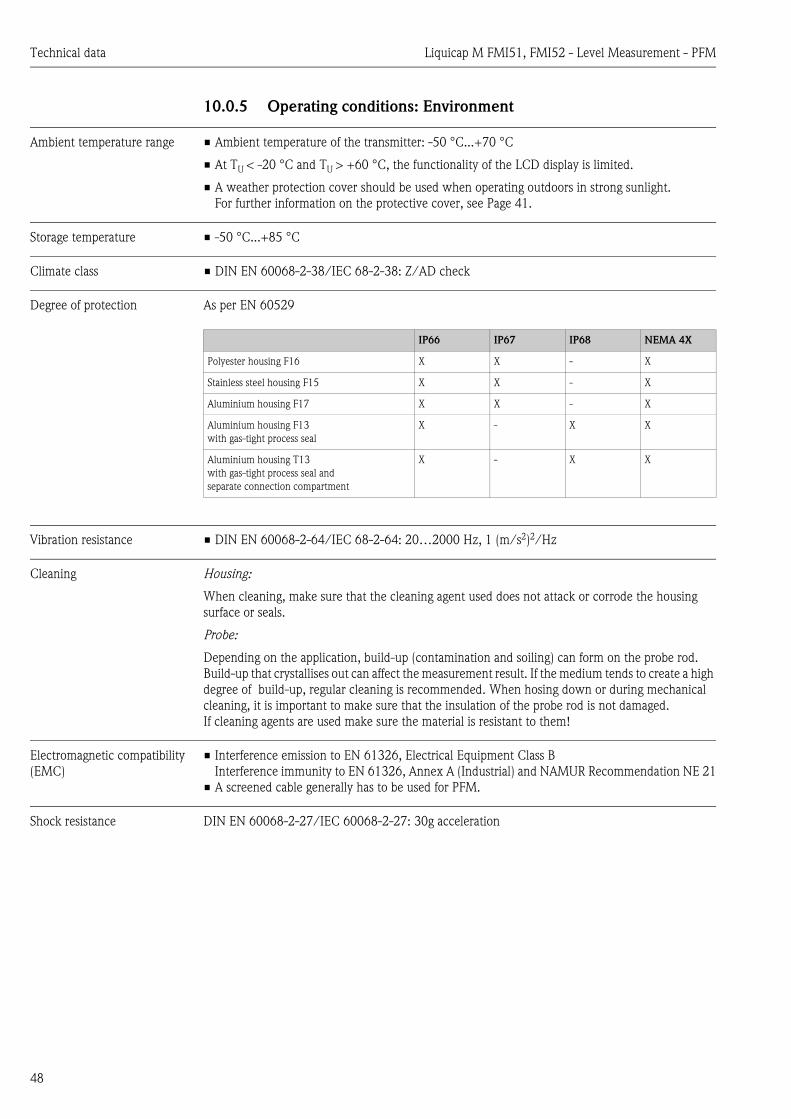
10.0.5 Operating conditions: Environment
Ambient temperature range • Ambient temperature of the transmitter: -50 °C...+70 °C
• At TU < -20 °C and TU > +60 °C, the functionality of the LCD display is limited.
• A weather protection cover should be used when operating outdoors in strong sunlight. For further information on the protective cover, see Page 41.
Storage temperature • -50 °C...+85 °C
Climate class • DIN EN 60068-2-38/IEC 68-2-38: Z/AD check
Degree of protection As per EN 60529
Vibration resistance • DIN EN 60068-2-64/IEC 68-2-64: 20…2000 Hz, 1 (m/s2)2/Hz
Cleaning Housing:
When cleaning, make sure that the cleaning agent used does not attack or corrode the housing surface or seals.
Probe:
Depending on the application, build-up (contamination and soiling) can form on the probe rod. Build-up that crystallises out can affect the measurement result. If the medium tends to create a high degree of build-up, regular cleaning is recommended. When hosing down or during mechanical cleaning, it is important to make sure that the insulation of the probe rod is not damaged. If cleaning agents are used make sure the material is resistant to them!
Electromagnetic compatibility (EMC)
• Interference emission to EN 61326, Electrical Equipment Class BInterference immunity to EN 61326, Annex A (Industrial) and NAMUR Recommendation NE 21
• A screened cable generally has to be used for PFM.
Shock resistance DIN EN 60068-2-27/IEC 60068-2-27: 30g acceleration
IP66 IP67 IP68 NEMA 4X
Polyester housing F16 X X - X
Stainless steel housing F15 X X - X
Aluminium housing F17 X X - X
Aluminium housing F13with gas-tight process seal
X - X X
Aluminium housing T13with gas-tight process seal andseparate connection compartment
X - X X

Liquicap M FMI51, FMI52 - Level Measurement - PFM Technical data
49
10.0.6 Operating conditions: Process
Process temperature range With compact housing
The following diagram applies to:• Rod and rope version• Insulation: PTFE, PFA, FEP
L00-FTI5xxxx-05-05-xx-xx-030
Ta = ambient temperature Tp = process temperature
! Note! Only relevant for FMI51!If the additional option B (LABS free) was selected, the minimum ambient temperature Ta is –40°C.
Pressure and temperature derating
For process connections ½"; ¾" and 1"Rod insulation: PTFERope insulation: FEP, PFA
! Note! See also "Process connections" on Page 19 ff.
L00-FMI5xxxx-05-05-xx-xx-008
Pp : Process pressureTp : Process temperature
Ta
0
0
TP
–40 –20–60 80 120 160 180
80
60
40
20
–80
–80/–25
200
–60
–40
–20
20 40 60 100 140
–40/–40
+20/–50
+200/+38
+80/+70
TP
Ta
°C
°C
bar
Pp
0
0–40 –20–60 80 120 160 180
40
20
–80 +200/–1
20 40 60 100 140
+200/+2
+50/+25
TP
°C

Technical data Liquicap M FMI51, FMI52 - Level Measurement - PFM
50
For process connections 1½"Rod insulation: PTFE, PFARope insulation: FEP, PFA
! Note! See also "Process connections" on Page 19 ff.
L00-FMI5xxxx-05-05-xx-xx-010
Pp : Process pressureTp : Process temperature
With fully insulated screening:
L00-FMI5xxxx-05-05-xx-xx-012
Pp : Process pressureTp : Process temperature
! Note! In the case of flange process connections, the maximum pressure is limited by the nominal pressure of the flange.
Process pressure limits The process pressure limits depend on the process connection. For further information refer to Chapter 3.3 ("Installation conditions", "Process connections")
bar
Pp
0
0–40 –20–60 80 120 160 180
60
40
80
20
–80 +200/–1
20 40 60 100 140
+200/+20
+80/+60
+40/+100
TP
°C
100
bar
Pp
0
0–40 –20–60 80 120 160 180
60
40
20
–80 +200/–1
20 40 60 100 140
+200/+2
+50/+50
TP
°C

Liquicap M FMI51, FMI52 - Level Measurement - PFM Technical data
51
State of aggregation Liquid
Liquicap M operational range
10.0.7 Mechanical construction
See "Installation" section, "Installation instructions" on Page 17 ff.
10.0.8 Certificates and approvals
CE mark The devices are designed to meet state-of-the-art safety requirements, have been tested and left the factory in a condition in which they are safe to operate. The devices comply with the applicable standards and regulations that are listed in the EC Declaration of Conformity and thus meet the legal requirements of the EC Directives. Endress+Hauser confirms the conformity of the device by affixing to it the CE-mark.
The measuring system is in conformity with the statutory requirements of the EC Directives. Endress+Hauser confirms that the device has been tested successfully by affixing the CE mark.
Ex approval See "Identification" section on Page 8 ff.
Other standards and guidelines
EN 60529Degrees of protection by housing (IP code)
EN 61010Protection measures for electrical equipment for measurement, control, regulation and laboratory procedures
EN 61326Interference emission (Class B equipment), interference immunity (Annex A - Industrial).
NAMURAssociation for Standards for Control and Regulation in the Chemical Industry
Typical DK values
Air 1
L00-FMI5xxxx-05-06-xx-en-000
Vacuum 1
General liquefied gases 1.2 - 1.7
Gasoline 1.9
Cyclohexane 2
Diesel fuel 2.1
General oils 2 - 4
Methyl ether 5
Butanol 11
Ammonia 21
Latex 24
Ethanol 25
Caustic soda 22 - 26
Acetone 20
Glycerine 37
Water 81
10–3
10–2
10–1
1
10
102
103
104
Conductivity [µS/cm]
independent of the conductivityand DK value (dielectric constant)
0 %...100 %factory calibration
e.g. Hydrocarbons witha water content under 0.1%,petrols, oils, solvents
e.g. Hydrocarbons witha higher water content,demineralised water
e.g. Water-based liquids,aqueous solutions of salts,acids and alkalis,aqueous dispersions and emulsions,wastewater, electrolytes, beverages
0 %factory calibration

Technical data Liquicap M FMI51, FMI52 - Level Measurement - PFM
52
10.0.9 Supplementary Documentation
Technical Information • Liquicap M FMI51, FMI52TI401F/00
Certificates ATEX safety instructions
• Liquicap M FMI51, FMI52ATEX II 1/2 G (EEx ia IIC/IIB T3...T6), II 1/2 D IP65 T 85 °CXA327F/00
• Liquicap M FMI51, FMI52ATEX II 1/2 G (EEx d (ia) IIC/IIB T3...T6)XA328F/00
Overfill protection DIBt (WHG)
• Liquicap M FMI51, FMI52ZE265F/00
Functional safety (SIL)
• Liquicap M FMI51, FMI52Under development
Control Drawings
• Liquicap M FMI51, FMI52Under development

Liquicap M FMI51, FMI52 - Level Measurement - PFM Technical data
53

Technical data Liquicap M FMI51, FMI52 - Level Measurement - PFM
54


www.endress.com/worldwide
BA297F/00/en/12.0571000300CCS/FM+SGML 6.0 71000300