OPERATING INSTRUCTIONS - Ideal VacuumFig. 1: MVP 160-3 14 Fig. 2: IN and EX connections on diaphragm...
42
OPERATING INSTRUCTIONS EN Translation of the Original MVP 160-3 Diaphragm pump
Transcript of OPERATING INSTRUCTIONS - Ideal VacuumFig. 1: MVP 160-3 14 Fig. 2: IN and EX connections on diaphragm...
OPERATING INSTRUCTIONS EN
Translation of the Original
MVP 160-3Diaphragm pump

Dear Customer,Thank you for choosing a Pfeiffer Vacuum product. Your new diaphragm pump should support you in your individual application with full performance and without malfunctions. The name Pfeiffer Vacuum stands for high-quality vacuum technology, a comprehensive and complete range of top-quality products and first-class service. From this extensive, practical experience we have gained a large volume of information that can contribute to efficient deployment and to your personal safety.In the knowledge that our product must avoid consuming work output, we trust that our product can offer you a solution that supports you in the effective and trouble-free implementation of your individual application.Please read these operating instructions before putting your product into operation for the first time. If you have any questions or suggestions, please feel free to contact [email protected] operating instructions from Pfeiffer Vacuum can be found in the Download Center on our website.
Disclaimer of liabilityThese operating instructions describe all models and variants of your product. Note that your product may not be equipped with all features described in this document. Pfeiffer Vacuum constantly adapts its products to the latest state of the art without prior notice. Please take into account that online operating instructions can deviate from the printed operating instructions supplied with your product.Furthermore, Pfeiffer Vacuum assumes no responsibility or liability for damage resulting from the use of the product that contradicts its proper use or is explicitly defined as foreseeable misuse.
CopyrightThis document is the intellectual property of Pfeiffer Vacuum and all contents of this document are protected by copyright. They may not be copied, altered, reproduced or published without the prior written permission of Pfeiffer Vacuum.We reserve the right to make changes to the technical data and information in this document.
2/42

Table of contents
1 About this manual 71.1 Validity 7
1.1.1 Related documents 71.1.2 Variants 7
1.2 Target group 71.3 Conventions 7
1.3.1 Instructions in the text 71.3.2 Pictographs 81.3.3 Stickers on the product 81.3.4 Abbreviations 8
2 Safety 92.1 General safety instructions 92.2 Safety instructions 92.3 Safety precautions 102.4 Usage limits of the vacuum pump 112.5 Proper use 112.6 Foreseeable improper use 12
3 Transportation and Storage 133.1 Transporting the vacuum pump 133.2 Storing the vacuum pump 13
4 Product description 144.1 Identifying the product 144.2 Shipment 144.3 Vacuum pump design and function 14
5 Installation 155.1 Installing the vacuum pump 155.2 Connecting the pumping stages 155.3 Connecting the vacuum side 165.4 Connecting the exhaust side 165.5 Establishing an electrical connection 17
6 Operation 186.1 Switching on and operating the vacuum pump 186.2 Switching off the vacuum pump 19
7 Decommissioning the vacuum pump for long periods 20
8 Maintenance 218.1 General 218.2 Maintenance intervals 218.3 Dismantling the distributor 218.4 Disassembling the diaphragm head 228.5 Checking and replacing parts 238.6 Cleaning contaminated parts 248.7 Replacing the diaphragm 248.8 Replacing the valves 268.9 Installing the diaphragm head 278.10 Installing the distributor 288.11 Checking vacuum pump function 28
9 Troubleshooting 30
10 Service solutions from Pfeiffer Vacuum 32
Table of contents
3/42

11 Spare parts 34
12 Accessories 35
13 Technical data and dimensions 3613.1 General 3613.2 Substances in contact with the media 3613.3 Technical data 3713.4 Dimensions 3813.5 Characteristics 38
Declaration of conformity 40
Table of contents
4/42
List of tablesTbl. 1: Abbreviations used in this document 8Tbl. 2: Usage limits of the vacuum pump 11Tbl. 3: Typical life with normal use 21Tbl. 4: Diaphragm attachments 24Tbl. 5: Troubleshooting 31Tbl. 6: MVP 160-3 spare parts list 34Tbl. 7: Accessories 35Tbl. 8: Conversion table: Pressure units 36Tbl. 9: Conversion table: Units for gas throughput 36Tbl. 10: Materials that make contact with the process media 37Tbl. 11: Technical data, MVP 160-3 37
List of tables
5/42

List of figuresFig. 1: MVP 160-3 14Fig. 2: IN and EX connections on diaphragm heads 15Fig. 3: Distributor: Intake side distributor (left) and pressure side distributor (right) 16Fig. 4: Connection diagram: MVP 160-3 with single phase AC motor 17Fig. 5: Mains switch 19Fig. 6: Mains switch 19Fig. 7: Loosen the compression couplings on the diaphragm head 22Fig. 8: Dismantling both distributors 22Fig. 9: Disconnecting diaphragm head 23Fig. 10: Disassembling the diaphragm head 23Fig. 11: Diaphragm key (accessory) 25Fig. 12: Diaphragm key with inlaid diaphragm parts 25Fig. 13: Diaphragm and associated parts 25Fig. 14: Correct positioning of valves in diaphragm head 26Fig. 15: Valves 26Fig. 16: Installing the diaphragm head 27Fig. 17: Secure diaphragm head 27Fig. 18: Install both distributors 28Fig. 19: Screw couplings on diaphragm head 28Fig. 20: Dimensions in mm 38Fig. 21: Air pumping speed at 50 Hz 38Fig. 22: Air pumping speed at 60 Hz 39
List of figures
6/42

1 About this manualIMPORTANTRead carefully before use.Keep the manual for future consultation.
1.1 ValidityThese operating instructions are for customers of Pfeiffer Vacuum. They describe the function of the designated product and provide the most important information for safe usage of the product. The de-scriptions comply with applicable directives. All information provided in these operating instructions refer to the current development status of the product. The documentation remains valid as long as the cus-tomer does not modify the product in any way.
1.1.1 Related documents
Designation Document
Declaration of conformity A component of these instructions
Current documents are available from the Pfeiffer Vacuum Download Center.
1.1.2 VariantsThese operating instructions apply to the diaphragm pump with the following part number:
Part number Designation
PK T01 400 MVP 160-3
1.2 Target groupThis operating instructions are aimed at all persons performing the following activities on the product:
● transport,● setup (installation),● usage and operation,● decommissioning,● maintenance and cleaning,● storage or disposal.
The work described in this document is only permitted to be performed by persons with the appropriate technical qualifications (expert personnel) or who have received the relevant training from Pfeiffer Vac-uum.
1.3 Conventions
1.3.1 Instructions in the textUsage instructions in the document follow a general structure that is complete in itself. The required ac-tion is indicated by an individual step or multi-part action steps.Individual action stepA horizontal, solid triangle indicates the only step in an action.
► This is an individual action step.Sequence of multi-part action stepsThe numerical list indicates an action with multiple necessary steps.
1. Step 12. Step 23. ...
About this manual
7/42

1.3.2 PictographsPictographs used in the document indicate useful information.
Note
Tip
1.3.3 Stickers on the productThis section describes all the stickers on the product along with their meaning.
Rating plateThe rating plate is located on the housing panel.
General warning signThe label provides a general warning of potential hazards, in this case in relation to the hot surfaces warning.
Warning of hot surfacesThe label warns of hot surfaces during operation or immediately after switching off the vacuum pump.
1.3.4 Abbreviations
Abbreviation Meaning in this document
DN Nominal diameter (from the French: diamètre nominal)
FPM Fluoropolymer rubber
MVP Diaphragm vacuum pump
NN Mean sea level
PA Polyamide
PE Earthed conductor (protective earth)Polyethylene
WAF width across flats
Tbl. 1: Abbreviations used in this document
About this manual
8/42

2 Safety
2.1 General safety instructionsThis document includes the following four risk levels and one information level.
DANGERImminent dangerIndicates a hazardous situation which, if not avoided, will result in death or serious injury.
► Instructions on avoiding the hazardous situation
WARNINGPossibly imminent dangerIndicates a hazardous situation which, if not avoided, could result in death or serious injury.
► Instructions on avoiding the hazardous situation
CAUTIONPossibly imminent dangerIndicates a hazardous situation which, if not avoided, could result in minor or moderate injury.
► Instructions on avoiding the hazardous situation
NOTICEDanger of property damageNotice is used to address practices not related to physical injury.
► Instructions on avoiding property damage
Notes, tips or examples indicate important information on the product or on this document.
2.2 Safety instructionsAll safety instructions in this document are based on the results of the risk assessment carried out in accordance with Machinery Directive 2006/42/EC Annex I and EN ISO 12100 Section 5. As far as appli-cable, all unit life cycle phases have been considered.
Risks during transport
WARNINGDanger of serious injury due to falling objectsDue to falling objects there is a risk of injuries to limbs through to broken bones.
► Take particular care and pay special attention when transporting products manually.► Do not stack the products.► Wear protective equipment, e.g. safety shoes.
Safety
9/42
Risks during installation
DANGERRisk to life due to electric shockAn improperly earthed unit is a potential threat to life in the event of a fault.
► Conduct the electrical connection in accordance with locally applicable regulations.► Make sure that the local mains voltage and frequency match rating plate specifications.► Use only a 3-pin mains cable and extension cables with properly connected protective earthing
(earthed conductor).► Plug the mains plug into a socket with earthing contact only.
– Protection must not be impaired by an extension with no earthed conductor.► Always connect the mains cable prior to all other cables, to ensure continuous protective earth-
ing.– In reverse: always disconnect all other cables prior to disconnecting the mains cable.
CAUTIONRisk of injury from bursting due to high pressure in the exhaust lineFaulty or insufficient exhaust lines cause hazardous situations, e.g. increase in exhaust pressure. There is a risk of bursting. It is not possible to rule out the risk of injuries due to broken pieces flying around, high escaping pressure and damage to the equipment.
► Lay the exhaust line without shut-off units.► Observe the permissible pressures and pressure differentials of the product.► Check the exhaust line regularly for correct function.
Risks during operation
WARNINGDanger of poisoning due to emission of toxic process gases from the exhaustDuring operation with no exhaust line, the vacuum pump allows exhaust gases and vapors to escape freely into the air. In processes involving toxic media, there is a risk of injury and danger to life due to poisoning.
► Observe the relevant regulations for handling toxic substances.► Safely purge toxic process gases via an exhaust line.► Use suitable filter equipment to separate toxic substances.
WARNINGRisk of burns on hot surfacesDuring vacuum pump operation, exposed surfaces reach high temperatures. There is a risk of burn-ing.
► Allow the vacuum pump to cool down before carrying out any work.► Wear protective gloves (in accordance with EN 420).
Risks during maintenance
WARNINGRisk of burns on hot surfacesDuring vacuum pump operation, exposed surfaces reach high temperatures. There is a risk of burn-ing.
► Allow the vacuum pump to cool down before carrying out any work.► Wear protective gloves (in accordance with EN 420).
2.3 Safety precautionsThe product is designed according to the latest technology and recognized safety engineering rules.
Safety
10/42

Nevertheless, improper use can result in danger to operator all third party life and limb, and product damage and additional property damage.
Duty to provide information on potential dangersThe product holder or user is obliged to make all operating personnel aware of dangers posed by this product.Every person who is involved in the installation, operation or maintenance of the product must read, understand, and adhere to the safety-related parts of this document.
Infringement of conformity due to modifications to the productThe Declaration of Conformity from the manufacturer is no longer valid if the operator changes the original product or installs additional equipment.
● Following installation into a system, the operator is required to check and re-evaluate as necessary the conformity of the overall system in the context of the relevant Europe-an Directives before commissioning that system.
General safety precautions for working with the vacuum pump► Observe all applicable safety and accident prevention regulations.► Check that all safety measures are observed at regular intervals.► Do not expose body parts to the vacuum.► Always ensure a secure connection to the earthed conductor (PE).► Never disconnect plug connections during operation.► Observe the above shutdown procedures.► Keep lines and cables away from hot surfaces (> 70 °C).► Never fill or operate the unit with cleaning agents or cleaning agent residues.► Do not carry out your own conversions or modifications on the unit.► Observe the unit protection class prior to installation or operation in other environments.► Observe statutory and local regulations regarding solvents handling.► Never operate an open or faulty unit.► Before carrying out any maintenance, first allow the unit to cool and disconnect it from the vacuum
equipment.► Disconnect the vacuum pump from the mains prior to every intervention, and wait an additional
five seconds until the capacitors have discharged.► Implement suitable safety precautions where unintentional vacuum pump venting can cause haz-
ards.– Power failures can cause unintentional venting.
2.4 Usage limits of the vacuum pump
Operations condition, status Intake pressure Permissible gas temperature range
Continuous operation > 100 hPa (high gas load) +10°C to +40°C
Continuous operation < 100 hPa (low gas load) 0°C to +60°C *
Short-term (< 5 minutes) < 100 hPa (low gas load) -10°C to +80°C *
Tbl. 2: Usage limits of the vacuum pump
2.5 Proper use● The vacuum pump may only be used for vacuum generation.● It is not permissible to operate the vacuum pump with accessories not recommended by Pfeiff-
er Vacuum.● Always observe installation, commissioning, operating, and maintenance instructions.
Safety
11/42

2.6 Foreseeable improper useImproper use of the product invalidates all warranty and liability claims. Improper use is any, even unin-tended, use, which is contrary to the product purpose; and in particular:
● Pumping of corrosive media● Pumping explosive media● Pumping corrosive, explosive, radioactive, or volatile media● Pumping of gases that introduce an ignition source to the suction chamber● Pumping of gases that contain impurities such as particles, dust, or condensate● Pumping of fluids● Pumping FPM-solubilizing media● Pumping vapors from combustible liquids● Pumping pressurized media (> atmospheric pressure)● Pumping media that can condense or cause adhering deposits to form in the suction chamber● Use of the vacuum pump outside the specified area of application● Using the vacuum pump below ground● Using the vacuum pump to generate pressure● Using the vacuum pump in systems in which sporadic loads and vibrations or periodic forces act
on the unit● Using the vacuum pump in strong electrical, magnetic, or electromagnetic fields● Connection to vacuum pumps or equipment which are not suitable for this purpose according to
their operating instructions● Connection to devices with exposed live parts● Connecting to sockets without earthing contact● Using lubricants not specified by Pfeiffer Vacuum● Using pipes to lift the vacuum pump● Use of accessories or spare parts that are not listed in these instructions● Using the vacuum pump as a climbing aid● Using the connection lines between the diaphragm heads as carrying handles● Using the vacuum pump in ambient conditions that do not meet the specified IP protection class
limits
Safety
12/42

3 Transportation and Storage
3.1 Transporting the vacuum pump
WARNINGDanger of serious injury due to falling objectsDue to falling objects there is a risk of injuries to limbs through to broken bones.
► Take particular care and pay special attention when transporting products manually.► Do not stack the products.► Wear protective equipment, e.g. safety shoes.
NOTICEDamage caused during transportTransport in unsuitable packaging or failure to install all transport locks can damage the product.
► Observe the transport instructions.► Always transport the vacuum pump in its original packaging.► Transport the vacuum pump using only the transport handles provided.► Always use sealed and impact-proof packaging for the vacuum pump.► Seal inlet and outlet ports (for example using transport caps).► Reattach transport locks prior to every transport.
Instructions for safe transport1. Observe weight specified on the rating plate.2. Wherever possible, always transport or ship the vacuum pump in its original packaging.3. Always carry the vacuum pump with both hands.4. Remove the protective cover only immediately prior to installation.
3.2 Storing the vacuum pump
NOTICEDamage caused by improper storageImproper storage leads to damage to the vacuum pump.
► Store the vacuum pump in a cool, dry, dust-free place, where it is protected against impacts.► Seal inlet and outlet ports (e.g. using transport caps).► Maintain the permissible storage temperature. (See technical data)
Transportation and Storage
13/42

4 Product description
4.1 Identifying the productYou will need all the data from the rating plate to safely identify the product when communicating with Pfeiffer Vacuum.Recording rating plate data
1. Read the data on the product rating plate.2. Record this data.3. Always have all rating plate specifications to hand.
4.2 Shipment● Diaphragm vacuum pump● Operating instructions
4.3 Vacuum pump design and function4
8
6
5
9
3
2
1
7
Fig. 1: MVP 160-3
1 Vacuum connection (inlet, DN 25 ISO-KF) 6 Mains switch2 Distributor, intake side 7 Pressure connection (with silencer)3 Handle (2x) 8 Rating plate on housing panel4 Mains plug 9 Motor fan5 Distributor, pressure side
The diaphragm vacuum pump is a three stage, dry compressing vacuum pump. This means that the supplied medium does not come into contact with any lubricant.The vacuum pump is a positive displacement pump with a periodic change in suction chamber size, produced by the movement of the diaphragm. The gas flow causes the valves to open and close auto-matically.The pump units are connected directly to the drive motor (AC motor).The vacuum pump is equipped with a pressure side silencer as standard.
Product description
14/42

5 Installation
5.1 Installing the vacuum pumpProcedure
1. Place the vacuum pump on a flat, horizontal surface.2. Make sure that the vacuum pump is stable and secure, with no additional mechanical contact
other than the pump feet.3. Make sure that the system to be evacuated and all hose connections are mechanically stable.4. Never install the vacuum pump on a soft surface (such as foam), as this impairs air supply to
the fan.5. Ensure for sufficient air supply if you install the vacuum pump in an enclosed housing or at a
high ambient temperature. Provide external forced ventilation if necessary.– Minimum 5 cm between fan (on pump underside) and adjacent parts (for example housing,
walls, etc.)6. If you install the vacuum pump at an installation altitude of > 1000 m AMSL, you must imple-
ment measures in accordance with DIN VDE 0530 to ensure an adequate cooling air supply.7. Anchor the vacuum pump to the supporting surface in the event of stationary installation.8. Use elastic hose pieces or bellows for anchoring.
– This prevents mechanical forces resulting from rigid connection lines.9. Maintain ambient conditions.
10. Before switching on, allow the vacuum pump to acclimatize.– If the vacuum pump is brought into the operating area from a cold environment, condensation
can form.
5.2 Connecting the pumping stages
NOTICEVacuum pump damage caused by overpressureMixing up the connections causes overpressure overload. The vacuum pump can be started only against max. 1 bar differential pressure between inlet and outlet; otherwise the motor jams and sus-tains damage.
► Make sure that the distributor is installed correctly on the diaphragm heads, before connecting the vacuum pump to the vacuum equipment.
► Before commissioning, make completely sure that the pressure side pressure is below the per-missible limit.
The intake connections of the vacuum pump are marked “IN” and the outlets “EX” on the individual dia-phragm heads.
Fig. 2: IN and EX connections on diaphragm heads
IN Intake connection EX Outlet
Installation
15/42

Fig. 3: Distributor: Intake side distributor (left) and pressure side distributor (right)
5.3 Connecting the vacuum sidePreventing pressure lossesUsing the shortest possible vacuum connection lines with large nominal diameter prevents pressure losses.
Condensate separatorPfeiffer Vacuum recommends the installation of a condensate separator in case vapors are formed from moisture during evacuation.
Procedure1. Remove the locking cap from the vacuum connection.2. Install the connection between vacuum pump and vacuum system so that it is as short as possi-
ble.3. Install a condensate separator upstream of the vacuum pump.4. Connect the vacuum pump to the vacuum system using the vacuum connection.
5.4 Connecting the exhaust sideCondensate separatorPfeiffer Vacuum recommends installing a condensate separator, with condensate drain at the lowest point of the exhaust line.
Procedure1. Observe the official accident prevention regulations.
– This applies in particular where you install a shut-off unit for internal operating reasons, mean-ing that overpressure can build in the line.
2. Remove protective caps.3. Install the line downward from the vacuum pump so that condensation does not flow back into the
pump.4. Connect the vacuum pump and vacuum chambers with the shortest possible connection, with a
minimum nominal diameter equal to that of the vacuum connection.5. Make sure that no piping system forces are acting on the vacuum pump.6. Support or hang the pipes.7. Only use the silencer at low gas throughput, and check it regularly to ensure that it is unobstruct-
ed.
Installation
16/42
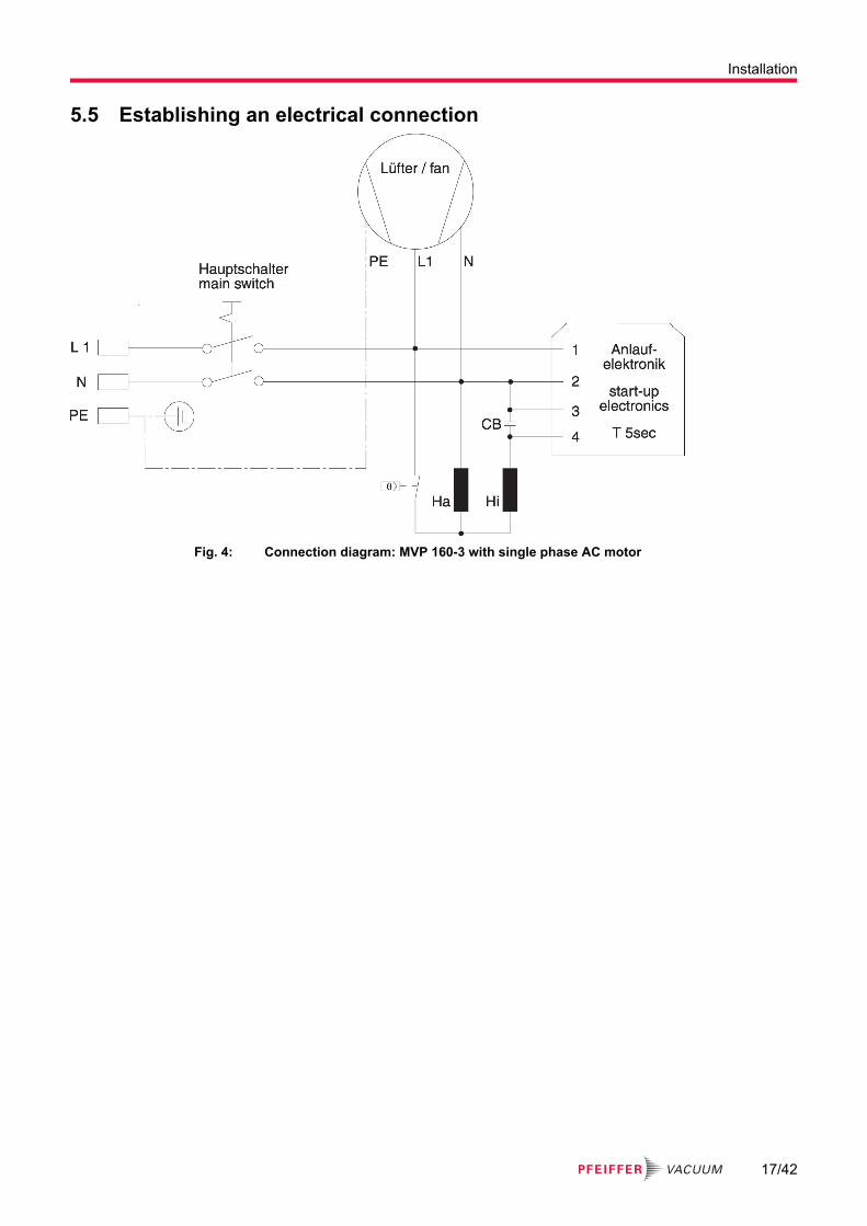
5.5 Establishing an electrical connection
Fig. 4: Connection diagram: MVP 160-3 with single phase AC motor
Installation
17/42

6 Operation
6.1 Switching on and operating the vacuum pump
WARNINGDanger of poisoning due to emission of toxic process gases from the exhaustDuring operation with no exhaust line, the vacuum pump allows exhaust gases and vapors to escape freely into the air. In processes involving toxic media, there is a risk of injury and danger to life due to poisoning.
► Observe the relevant regulations for handling toxic substances.► Safely purge toxic process gases via an exhaust line.► Use suitable filter equipment to separate toxic substances.
CAUTIONRisk of injury from bursting due to high pressure in the exhaust lineFaulty or insufficient exhaust lines cause hazardous situations, e.g. increase in exhaust pressure. There is a risk of bursting. It is not possible to rule out the risk of injuries due to broken pieces flying around, high escaping pressure and damage to the equipment.
► Lay the exhaust line without shut-off units.► Observe the permissible pressures and pressure differentials of the product.► Check the exhaust line regularly for correct function.
NOTICEDamage caused by water hammerThe sudden ingress of condensate can cause water hammer, as the vacuum pump cannot pump the additionally formed steam down quickly enough. Water hammer destroys the vacuum pump.
► Install a capacitor between the vacuum system and the vacuum pump.– This intercepts the fluid upstream of the vacuum pump.
NOTICEDamage caused by fluids and dustFluids and dust damage diaphragms and valves.
► Prevent ingress of particles and dusts to the vacuum pump.► Install a suitable filter upstream of the vacuum pump if necessary.► Avoid condensation in the vacuum pump and water hammer.► Observe the intended use.
NOTICEDamage caused by silencer contaminationAfter a long period of operation at high intake pressures or with dust-laden gases, the silencer can become congested. If the silencer becomes contaminated, an internal overpressure builds that dam-ages bearings, diaphragms, and valves.
► Replace a contaminated silencer.► Make sure that the exhaust line is unobstructed.► Ideally, use a hose nozzle as an outlet.
Achieving throughput and ultimate pressureThe vacuum pump achieves the specified throughput and ultimate pressure values once the operating temperature has been reached (after approx. 15 minutes).
Operation
18/42

1
Fig. 5: Mains switch
1 Mains switchProcedureYou can switch on the vacuum pump at any time.
1. Press the mains switch.
6.2 Switching off the vacuum pump
1
Fig. 6: Mains switch
1 Mains switchProcedureYou can switch off the vacuum pump at any time.
1. Allow the vacuum pump to run on for a few more minutes with the intake port open.2. Press the mains switch.3. Clean and check the diaphragm heads when working with pump media that are corrosive to pump
materials or can cause formation of deposits.
Operation
19/42

7 Decommissioning the vacuum pump for long periodsProcedure
1. Switch off the vacuum pump.2. Vent the vacuum pump and allow it to cool down.3. Disconnect the vacuum pump from the vacuum equipment.4. Clean suction chamber.5. Seal flanges and any other openings.6. Store the vacuum pump in dry, dust-free rooms, within the specified ambient conditions.
– In areas with damp or aggressive atmospheres, we recommend packaging the vacuum pump in a plastic bag with a drying agent, and sealing it so that it is airtight.
– For storage durations longer than 2 years, we recommend you carry out maintenance and a lubricant change prior to recommissioning.
Decommissioning the vacuum pump for long periods
20/42

8 Maintenance
8.1 General
WARNINGRisk of burns on hot surfacesDuring vacuum pump operation, exposed surfaces reach high temperatures. There is a risk of burn-ing.
► Allow the vacuum pump to cool down before carrying out any work.► Wear protective gloves (in accordance with EN 420).
NOTICEDamage caused by pointed or sharp-edged toolsSharp-edged tools damage pump parts during maintenance.
► Never disconnect pump parts such as diaphragm heads using pointed or sharp-edged tools.► Never use pointed or sharp-edged tools to lift diaphragms.► If necessary, use a rubber mallet to loosen parts.
8.2 Maintenance intervalsDismantle the vacuum pump only to the extent necessaryDismantle the vacuum pump only to the extent required for maintenance.Use only genuine parts as listed in the spare parts list.
Valves and diaphragms are wear parts.
Component Operating hours
Diaphragm 15,000
Valves 15,000
Motor bearing 40,000
Motor capacitors 10,000-40,000
Tbl. 3: Typical life with normal use
You must check wear parts by the time the achieved pressure values drop off at the latest.Checking wear parts
1. Clean suction chamber2. Clean diaphragms3. Clean valves4. Check and clean diaphragm heads at regular intervals (depending on the individual case)5. Inspect diaphragms and valves for cracks.6. Replace defective parts.
8.3 Dismantling the distributorIt is not necessary to remove the connection hoses from the distributor screw couplings.
Maintenance
21/42

Fig. 7: Loosen the compression couplings on the diaphragm head
2
1
3
4
25
22 17
5
Fig. 8: Dismantling both distributors
1 Countersunk screws 4 Countersunk screws2 Intake side distributor 5 Cover plate3 Pressure side distributor
Procedure
Required tools● Open-end wrench (17 WAF)● Crosshead screwdriver
1. Unscrew the screw couplings from all diaphragm heads using the open-end wrench.2. Unscrew the countersunk screws using the crosshead screwdriver.3. Remove the entire intake side distributor, including all fittings.4. Unscrew the countersunk screws using the crosshead screwdriver.5. Remove the entire pressure side distributor and cover panel, including all fittings.
8.4 Disassembling the diaphragm head
NOTICEDamage caused by pointed or sharp-edged toolsSharp-edged tools damage pump parts during maintenance.
► Never disconnect pump parts such as diaphragm heads using pointed or sharp-edged tools.► Never use pointed or sharp-edged tools to lift diaphragms.► If necessary, use a rubber mallet to loosen parts.
Maintenance
22/42

Fig. 9: Disconnecting diaphragm head
35
1
37
12
2
3
4
5
Fig. 10: Disassembling the diaphragm head
1 Diaphragm head 4 Head cover2 O-rings 5 Connection rod3 Valves
Procedure
Required tools● Allen key (5 WAF)● Rubber mallet
1. Use the Allen key to unscrew the four cheesehead screws from the diaphragm head.2. Remove top of housing (diaphragm head and head cover).
– Do not allow the head cover to fall out of the diaphragm head when doing so.3. Remove the head cover from the diaphragm had in order to check the valves.4. Note the position of the valves and O-rings, and remove them.5. Move the connection rod by rotating the eccentric bushing (on the front of the connection rod) to a
position where the diaphragm rests centrally and flush on the supporting surface in the housing opening.
8.5 Checking and replacing partsProcedure
1. Check all parts for damage and contamination.2. Clean contaminated parts.3. Replace damaged valves.4. Replace damaged diaphragms.
Maintenance
23/42

8.6 Cleaning contaminated parts
NOTICEDamage caused by unsuitable cleaning agentsUnsuitable cleaning agents damage pump parts.
► Use only approved cleaning agents to clean pump parts.► Never use soluble detergents.
Procedure
Required consumables● Isopropanol
1. Clean contaminated parts with isopropanol.2. Allow parts to dry well.
8.7 Replacing the diaphragm
NOTICEDamage caused by unsuitable auxiliary toolUsing unsuitable tools damage the diaphragm and associated components.
► Never use the diaphragm key with auxiliary tools (for example pliers or an Allen key without tor-que limitation).
Spacer disksTake care with any spacer disks that may be between the diaphragm support disk and con-nection rod. Keep the spacer disks for each cylinder separate, and reinstall the same num-ber of original spacer disks.Too few spacer disks: Vacuum pump does not attain final vacuum.Too many spacer disks: Vacuum pump bangs (noise development).
Double diaphragmYou have to position the double diaphragms with the printed sides facing outwards.
Depending on the pump design, two diaphragm attachments may be possible when replacing the dia-phragm:
Attachment with countersunk screw Form-fitted attachment
Design with bore Design with square hole
Tbl. 4: Diaphragm attachments
Maintenance
24/42

Fig. 11: Diaphragm key (accessory)
Fig. 12: Diaphragm key with inlaid diaphragm parts
35
12
1
2
3
4
Fig. 13: Diaphragm and associated parts
1 Diaphragm clamping disk 3 Diaphragm support disk2 Diaphragm 4 Connection rod
Procedure
Required tools● Diaphragm key (accessory)● Torque wrench (hex, size 6)
Required consumables● Gasoline or petroleum
1. Diaphragm with square hole: Remove the pre-punched interior of the new diaphragm.2. Carefully lift the side of the diaphragm.3. Using the diaphragm key, reach under the diaphragm and grasp the diaphragm support disk.4. Disconnect the diaphragm support disk using the diaphragm key.5. Unscrew the diaphragm support disk together with the diaphragm and diaphragm clamping disk.6. If necessary, disconnect the old diaphragm from the diaphragm support disk using gasoline or pe-
troleum.
Maintenance
25/42
7. Insert the new diaphragm between diaphragm clamping disk and diaphragm support disk.– When doing so, make sure that the square connecting bolt of the diaphragm clamping disk is
positioned correctly in the diaphragm support disk guide.8. Lift the side of the diaphragm and insert it carefully in the diaphragm key with the diaphragm
clamping disk and diaphragm support disk.– When doing so, do not kink the diaphragm excessively.
9. Bolt all parts together with the spacer disks and connection rod.10. Attach the torque wrench to the diaphragm key11. Tighten the screw fitting with the torque wrench.
– Tightening torque = 6 Nm
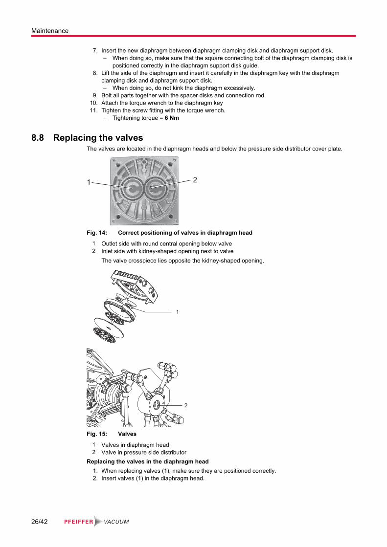
8.8 Replacing the valvesThe valves are located in the diaphragm heads and below the pressure side distributor cover plate.
1 2
Fig. 14: Correct positioning of valves in diaphragm head
1 Outlet side with round central opening below valve2 Inlet side with kidney-shaped opening next to valve
The valve crosspiece lies opposite the kidney-shaped opening.
1
2
Fig. 15: Valves
1 Valves in diaphragm head2 Valve in pressure side distributor
Replacing the valves in the diaphragm head1. When replacing valves (1), make sure they are positioned correctly.2. Insert valves (1) in the diaphragm head.
Maintenance
26/42

Replacing the valve in the pressure side distributor1. When replacing valve (2), make sure it is positioned correctly.2. Insert valve (2) in the pressure side distributor.
8.9 Installing the diaphragm head
35
1
37
12
2
3
4
5
Fig. 16: Installing the diaphragm head
1 Diaphragm head 4 Head cover2 O-rings 5 Connection rod3 Valves
Fig. 17: Secure diaphragm head
Required tools● Allen key (5 WAF)● Torque wrench
Procedure1. Ensure that the diaphragm rests centrally and flush on the supporting surface in the housing
opening.– If required, move the connection rod by rotating the eccentric bushing (front side of connec-
tion rod).– Make sure that valves and O-rings are positioned correctly.
2. Assemble head cover and diaphragm head.3. Ensure that the diaphragm is at the center.
– The diaphragm is evenly clamped between the pump housing and the head cover.4. Place top of housing (diaphragm head and head cover) on pump housing.
Maintenance
27/42

5. Fasten the 4 cheesehead screws on the diaphragm head.6. Tighten the 4 cheesehead screws diagonally.
– Do not tighten the cheesehead screws up to the stop.– Tightening torque = 12 Nm
8.10 Installing the distributor
2
1
3
4
25
22 17
5
Fig. 18: Install both distributors
1 Countersunk screws 4 Countersunk screws2 Intake side distributor 5 Cover plate3 Pressure side distributor
Fig. 19: Screw couplings on diaphragm head
Installing the distributor
Required tools● Open-end wrench (17 WAF)● Crosshead screwdriver
1. Hold the pressure side distributor, including cover plate and all fittings, in position on the vacuum pump.
2. Secure the countersunk screws using the crosshead screwdriver.3. Hold the intake side distributor, including all fittings, in position on the vacuum pump.4. Secure the countersunk screws using the crosshead screwdriver.5. Secure the screw couplings to all diaphragm heads using the open-end wrench.
8.11 Checking vacuum pump functionAfter working on the vacuum pump, you must check the final vacuum. Only where the vacuum pump reaches the specified final vacuum can a low pump leakage rate, and thus the prevention of potentially explosive mixtures in the pump interior, be ensured.
Maintenance
28/42

Checking function of individual diaphragm heads
Tools required● Standard vacuum gage
1. Measure the intake port pressure in every stage:– Using the standard vacuum gage, you must be able to measure < 110 hPa pressure values at
the intake port.2. If this pressure value is not reached, check the suction chamber.3. When doing so, check that valves and diaphragms are correctly seated (centrally to housing hole).
Checking final vacuumIf, following diaphragm valve replacement, the vacuum pump achieves the specified final vacuum value only after being run in for several hours, or unusual noise can be heard, proceed as follows:
1. Switch off the vacuum pump immediately in the event of unusual noise.2. carry out troubleshooting.
Maintenance
29/42

9 TroubleshootingProblem Possible causes Remedy
Vacuum pump not achieving ultimate pressure. (no through-put)
● Deposits in the vac-uum pump
● Clean and check the diaphragm heads.
● Condensate in the vacuum pump
● Operate the vacuum pump at at-mospheric pressure for a longer period.
● In-process steam for-mation
● Check the process parameters.
● Valves/diaphragms soiled/faulty
● Clean/replace the valves/diaphragms.
● Small flange connec-tion centering ring in-serted incorrectly
● Check the connection.
● Long, thin vacuum line ● Choose a line with a larger cross section.
● Leak in system 1. Eliminate the leak.2. Check the vacuum pump itself.
Connect the measurement in-strument directly to the pump in-let.
Unusual noises during opera-tion
● Valves/diaphragms faulty
● Replace valves/diaphragms.
● Dirt in suction cham-ber
● Clean suction chamber.
● Silencer loose or miss-ing
● Check/replace the silencer.
● Motor fan defective ● Replace the motor fan.
● Connection rod or mo-tor bearing defective
● Contact Pfeiffer Vacuum Service.
Vacuum pump does not start up.
● No mains voltage 1. Check the mains voltage.2. Check the mains fuse.3. Connect the mains plug.
● Phase failure ● Check the fuse.
● Thermal winding pro-tection has triggered. (Motor overloaded)
1. Allow the motor to cool down.2. Switch the mains switch off and
back on.
● Ambient temperature too low
● Heat up the vacuum pump.
● Valves/diaphragms soiled/faulty
● Clean/replace the valves/diaphragms.
● Overpressure in ex-haust line
● Open the exhaust line.
The vacuum pump switches off.
● Diaphragm bonded ● Clean the vacuum pump.
● Mains voltage incor-rect
● Correct the mains voltage in ac-cordance with the rating plate.
Troubleshooting
30/42

Problem Possible causes Remedy
Motor contactor tripped. ● Vacuum pump over-heating
1. Switch off the vacuum pump.2. Disconnect the mains plug.3. Allow the vacuum pump to cool
down.4. Determine and eliminate the
cause of overheating.
Vacuum pump blocked or con-nection rod stiff
● Contact Pfeiffer Vacuum Service.
Tbl. 5: Troubleshooting
Troubleshooting
31/42

10 Service solutions from Pfeiffer VacuumWe offer first class serviceLong vacuum component service life, coupled with low downtimes, are clear expectations that you have of us. We satisfy your needs with capable products and outstanding service.We are consistently striving to perfect our core competence, service for vacuum components. And our service is far from over once you’ve purchased a product from Pfeiffer Vacuum. It often enough really just begins then. In proven Pfeiffer Vacuum quality, of course.Our professional sales engineers and service technicians stand ready to provide hands-on support to you worldwide. Pfeiffer Vacuum offers a complete portfolio of service offerings, ranging from genuine spare parts right through to service agreements.
Take advantage of Pfeiffer Vacuum ServiceWhether for preventative on-site service from our field service, fast replacement with as-new replace-ment products or repair in a Service Center close to you; you have various options for upholding your equipment availability. Detailed information and addresses can be found on our website in the Pfeiff-er Vacuum Service section.
Advice on the optimum solution is available from your Pfeiffer Vacuum contact partner.For quick and smooth handling of the service process, we recommend the following steps:
1. Download the current form templates.─ Declaration of Service Request─ Service Request─ Declaration of Contamination
a. Dismantle all accessories and keep them (all external mounted parts as valve, inlet screen, etc.).
b. Drain the operating fluid/lubricant as necessary.c. Drain the cooling medium as necessary.
ANFORDERUNG SERVICE
ERKLÄRUNG KONTAMINIERUNG
2. Fill out the service request and the declaration of contamination.
3. Send the forms via email, fax or post to your local Service Center.
4. You will receive a response from Pfeiffer Vacuum.
Sending of contaminated productsNo units will be accepted if they are contaminated with micro-biological, explosive or radioactive sub-stances. If products are contaminated or if the declaration of contamination is missing, Pfeiffer Vacuum will contact the customer before starting maintenance. In addition, depending on the product and the level of contamination additional decontamination costs may be required.
Service solutions from Pfeiffer Vacuum
32/42

5. Prepare the product for transport in accordance with the details in the declaration of contamination.
a) Neutralize the product with nitrogen or dry air.b) Close all openings with airtight blank flanges.c) Seal the product in appropriate protective film.d) Only pack the product in suitable, stable transport containers.e) Observe the applicable transport conditions.
ERKLÄRUNG KONTAMINIERUNG
6 Affix the declaration of contamination to the outside of the packag-ing.
7 Then send your product to your local Service Center.
8 You will receive a confirmation message/a quotation from Pfeiff-er Vacuum.
For all service orders, our General Terms and Conditions of Sales and Supply and General Terms and Conditions of Repair and Maintenance apply to vacuum equipment and components.
Service solutions from Pfeiffer Vacuum
33/42
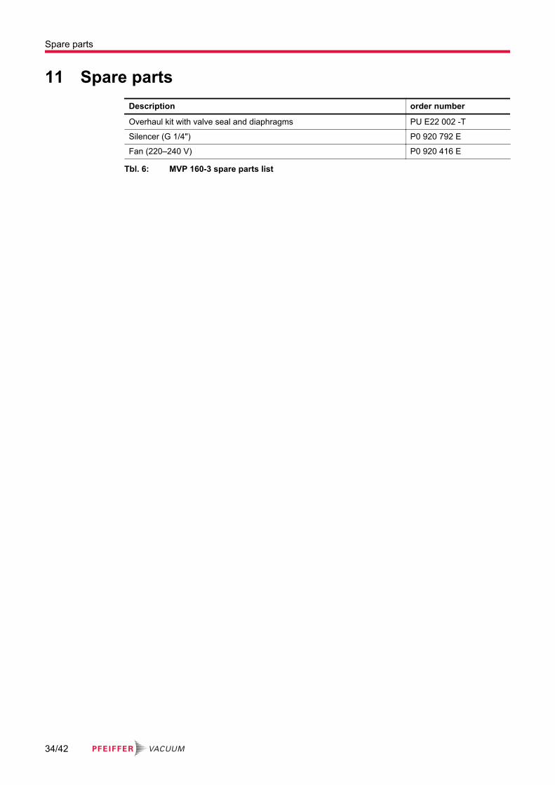
11 Spare partsDescription order number
Overhaul kit with valve seal and diaphragms PU E22 002 -T
Silencer (G 1/4") P0 920 792 E
Fan (220–240 V) P0 920 416 E
Tbl. 6: MVP 160-3 spare parts list
Spare parts
34/42

12 AccessoriesDescription order number
Diaphragm key (66 WAF) PK 050 172
Relay box, shielded, for backing pumps, 1-phase 7A for TC 110/120 and TCP 350, plug M8
PM 071 282 -X
Relay box, shielded, for backing pumps, 1-phase 7 A for TC 400/1200, TM 700 and TCP 350, M12
PM 071 284 -X
Mains cable 115/230 V without plug, rubber connector (right angle), 3 m PK 050 111
Mains cable 230 V with safety plug, right angle IEC 320/C13 socket, 2 m PK 050 109
Tbl. 7: Accessories
Accessories
35/42

13 Technical data and dimensions
13.1 GeneralBasis for the technical data of Pfeiffer Vacuum diaphragm pumps:
● Specifications according to PNEUROP committee PN5● ISO 21360:2012: “Vacuum technology - Standard methods for measuring vacuum-pump perform-
ance - General description”The following harmonized standards are fulfilled:
● IEC 61010-1● UL 61010-1● CSA 61010-1
mbar bar Pa hPa kPa Torr | mm Hg
mbar 1 1 · 10-3 100 1 0.1 0.75
bar 1000 1 1 · 105 1000 100 750
Pa 0.01 1 · 10-5 1 0.01 1 · 10-3 7.5 · 10-3
hPa 1 1 · 10-3 100 1 0.1 0.75
kPa 10 0.01 1000 10 1 7.5
Torr | mm Hg 1.33 1.33 · 10-3 133.32 1.33 0.133 1
1 Pa = 1 N/m2
Tbl. 8: Conversion table: Pressure units
mbar l/s Pa m3/s sccm Torr l/s atm cm3/s
mbar l/s 1 0.1 59.2 0.75 0.987
Pa m3/s 10 1 592 7.5 9.87
sccm 1.69 · 10-2 1.69 · 10-3 1 1.27 · 10-2 1.67 · 10-2
Torr l/s 1.33 0.133 78.9 1 1.32
atm cm3/s 1.01 0.101 59.8 0.76 1
Tbl. 9: Conversion table: Units for gas throughput
13.2 Substances in contact with the media
Pump parts Substances in contact with the media
Housing cover Aluminum alloy (AlSi12)
Head cover Aluminum alloy (AlSi12)
Diaphragm clamping disk Aluminum alloy (AlSi12)
Diaphragm Elastomer (FPM)
Valves Elastomer (FPM)
O-rings Elastomer (FPM)
Vacuum connection Stainless steel
Silencer Aluminum alloy/PA/PE
Overpressure valve Silicone
Hoses Polyethylene (PE)
Technical data and dimensions
36/42

Pump parts Substances in contact with the media
Compression couplings Anodized aluminum (AlCuMgPb)
Sealing rings Elastomer (FPM)
Tbl. 10: Materials that make contact with the process media
13.3 Technical data
Classification MVP 160-3
Order number PK T01 400
Flange (in) DN 25 ISO-KF
Flange (out) G 1/4” with silencer
Pumping speed at 50 Hz 9.6 m³/h
Pumping speed at 60 Hz 10.4 m³/h
Ultimate pressure without gas ballast ≤ 2 hPa
Exhaust pressure, max. 1100 hPa
Leak rate ≤ 2 · 10-3 Pa m³/s
Ambient temperature 10 – 40 °C
Temperature: Storage -10 – 60 °C
Emission sound pressure level without gas ballast or purge 52 ±1.5 dB(A)
Rotation speed at 50 Hz 1500 rpm
Rotation speed at 60 Hz 1800 rpm
Motor protection Thermal winding protection
Mains requirement: voltage, max. 230 V
Mains requirement: voltage (range) ± 10 %
Rated current absorption at 50 Hz 2.8 A
Rated current absorption at 60 Hz 2.7 A
Protection category IP20
Operating altitude, max. 2000 m
Weight 25 kg
Tbl. 11: Technical data, MVP 160-3
Technical data and dimensions
37/42

13.4 Dimensions≈ 222
111
≈ 2
94
15
1
34°
110
DN
25
≈ 486
242
20 10
V
M6
11
Fig. 20: Dimensions in mm
13.5 Characteristics
0.1
1
10
100
1 10 100 1000
P [hPa]
S [m
3/h
]
MVP 160-3 (50 Hz)
Fig. 21: Air pumping speed at 50 Hz
Technical data and dimensions
38/42

0.1
1
10
100
1 10 100 1000
P [hPa]
MVP 160-3 (60 Hz)
S [m
3/h
]
Fig. 22: Air pumping speed at 60 Hz
Technical data and dimensions
39/42

Declaration of conformity
We hereby declare that the product cited below satisfies all relevant provisions of the follow-ing EU Directives:
● Machinery 2006/42/EC (Annex II, no. 1 A)● Electromagnetic compatibility 2014/30/EU● Restriction of the use of certain hazardous substances 2011/65/EU
The authorized representative for the compilation of technical documents is Mr. Sebas-tian Oberbeck, Pfeiffer Vacuum GmbH, Berliner Straße 43, 35614 Aßlar, Germany.
Diaphragm vacuum pumpMVP 160-3
Harmonized standards and applied national standards and specifications:EN ISO 12100:2011
EN 61010-1:2011
IEC 61010-1:2010 (edition 3)
EN 1012-2:2011
EN 61326-1:2013
EN 50581:2013
Signature:
Pfeiffer Vacuum GmbHBerliner Straße 4335614 AßlarGermany
(Dr. Ulrich von Hülsen)Managing Director
Aßlar, 8/28/2017

41/42

*PU0077*
ed. B
- D
ate
1902
- P/
N:P
U00
77BE
N