
Operating Instructions Diesel engine - MTU Online · Operating Instructions Diesel engine 12V 4000...
248
Operating Instructions Diesel engine 12V 4000 M53R 16V 4000 M53R MS150036/02E
Transcript of Operating Instructions Diesel engine - MTU Online · Operating Instructions Diesel engine 12V 4000...

Operating InstructionsDiesel engine12V 4000 M53R16V 4000 M53R
MS150036/02E

Printed in Germany
© 2013 Copyright MTU Friedrichshafen GmbH
This Publication is protected by copyright and may not be used in any way whether in whole or in part without the priorwritten permission of MTU Friedrichshafen GmbH. This restriction also applies to copyright, distribution, translation, mi-crofilming and storage or processing on electronic systems including data bases and online services.
This handbook is provided for use by maintenance and operating personnel in order to avoid malfunctions or damageduring operation.
Subject to alterations and amendments.

Table of Contents1 Safety
1.1 Important provisions for all products 51.2 Personnel and organizational requirements 61.3 Transport 71.4 Safety regulations for maintenance and
repair work 81.5 Fire prevention and environmental
protection, fluids and lubricants, auxiliarymaterials 11
1.6 Standards for safety notices in the text 13
2 General Information
2.1 Engine side and cylinder designations 142.2 Product description 152.3 Engine layout 382.4 Sensors, actuators and injectors on 12V
engines – Overview 422.5 Sensors, actuators and injectors on 16V
engines – Overview 52
3 Technical Data
3.1 12V 4000 M53R engine data 723.2 16V 4000 M53R engine data 763.3 Engine – Main dimensions 803.4 Firing order 82
4 Operation
4.1 Controls 834.2 Putting the engine into operation after
extended out-of-service periods (>3 months) 844.3 Putting the engine into operation after
scheduled out-of-service-period 854.4 Starting the engine 864.5 Operational checks 874.6 Tasks after extended out-of-service periods
(>3 weeks) 884.7 Checks prior to start-up 894.8 Fuel treatment system – Putting into
operation 904.9 Fuel treatment system – Switching on 93
4.10 Fuel treatment system – Shutdown 944.11 Stopping the engine 954.12 Emergency engine stop 964.13 After stopping the engine 974.14 Plant – Cleaning 98
5 Maintenance
5.1 Maintenance task reference table [QL1] 99
6 Troubleshooting
6.1 Troubleshooting 1016.2 Fuel treatment system – Troubleshooting 1046.3 Engine governor ADEC (ECU 7) fault
messages for Series 4000 engines, marineapplication 105
6.4 ADEC engine governor – Fault codes 106
7 Task Description
7.1 Engine 1327.1.1 Engine – Barring manually 1327.1.2 Engine – Barring with starting system 134
7.2 Cylinder Liner 1357.2.1 Cylinder liner – Endoscopic examination 1357.2.2 Instructions and comments on endoscopic and
visual examination of cylinder liners 137
7.3 Valve Drive 1397.3.1 Valve gear – Lubrication 1397.3.2 Valve clearance – Check and adjustment 1407.3.3 Cylinder head cover – Removal and
installation 143
7.4 Injection Pump / HP Pump 1447.4.1 HP pump – Filling with engine oil 1447.4.2 HP pump – Relief bore check 145
7.5 Injection Valve / Injector 1467.5.1 Injector – Replacement 1467.5.2 Injector – Removal and installation 147
7.6 Fuel Filter 1527.6.1 Supplementary fuel filter – Overview 1527.6.2 Additional fuel filter – Replacement 1537.6.3 Fuel filter – Replacement 1547.6.4 Fuel prefilter – Differential pressure check
and adjustment of gauge 1567.6.5 Fuel prefilter – Draining 1577.6.6 Fuel prefilter – Flushing 1597.6.7 Fuel prefilter with water separator – Filter
element replacement 161
7.7 Exhaust Turbocharger 1637.7.1 Compressor wheel – Cleaning 163
7.8 Charge-Air Cooling 1717.8.1 Charge-air cooler – Checking condensate drain
for water discharge and obstruction 171
7.9 Air Filter 172
MS150036/02E 2013-11 | Table of Contents | 3
DCL-
ID: 0
0000
2950
3 - 0
01
7.9.1 Air filter – Replacement 1727.9.2 Air filter – Removal and installation 173
7.10 Air Intake 1747.10.1 Service indicator – Signal ring position check
(optional) 174
7.11 Starting Equipment 1757.11.1 Starter – Condition check 175
7.12 Lube Oil System, Lube Oil Circuit 1767.12.1 Engine oil – Level check 1767.12.2 Engine oil – Change 1777.12.3 Engine oil – Sample extraction and analysis 179
7.13 Oil Filtration / Cooling 1817.13.1 Checking oil indicator filter 1817.13.2 Engine oil filter – Replacement 1837.13.3 Centrifugal oil filter – Cleaning and filter
sleeve replacement 185
7.14 Coolant Circuit, General, High-TemperatureCircuit 1887.14.1 Drain and vent points 1887.14.2 Engine coolant level – Check 1927.14.3 Engine coolant – Change 1937.14.4 Engine coolant – Draining 1947.14.5 Engine coolant – Filling 1977.14.6 HT coolant pump – Relief bore check 1997.14.7 Engine coolant – Sample extraction and
analysis 2007.14.8 Engine coolant filter – Replacement 2017.14.9 Preheating unit 202
7.15 Raw Water Pump with Connections 2057.15.1 Raw water pump – Relief bore check 205
7.16 Battery-Charging Generator 2067.16.1 Battery-charging generator drive – Coupling
condition check 206
7.17 Engine Mounting / Support 2077.17.1 Engine mounting – Checking securing screws
for firm seating 207
7.18 Auxiliary PTO 2087.18.1 Bilge pump – Relief bore check 208
7.19 Fuel Supply System 2097.19.1 Water drain valve – Check 2097.19.2 Differential pressure gauge – Check 2107.19.3 Water level probe (3-in-1 rod electrode) –
Check 2117.19.4 Pump capacity – Check 2127.19.5 Coalescer filter element – Replacement 213
7.20 Wiring (General) for Engine/Gearbox/Unit 2157.20.1 Engine wiring harness ‒ Overview 2157.20.2 Engine wiring – Check 224
7.21 Accessories for (Electronic) EngineGovernor / Control System 2257.21.1 Limit switch for start interlock ‒ Check 2257.21.2 Engine Control Unit ECU 7 – Checking plug
connections 2267.21.3 Engine monitoring unit EMU – Plug
connection check 2277.21.4 Interface module EIM plug connections –
Check 2287.21.5 Engine Control Unit ECU 7 – Removal and
installation 2297.21.6 EMU 7 – Removal and installation 2307.21.7 Engine Interface Module EIM – Removal and
installation 2317.21.8 Diagnostic features of EIM 2327.21.9 CDC parameters – Reset 235
8 Appendix A
8.1 Abbreviations 2368.2 MTU contact persons/service partners 238
9 Appendix B
9.1 Special Tools 2399.2 Index 246
4 | Table of Contents | MS150036/02E 2013-11
DCL-
ID: 0
0000
2950
3 - 0
01

1 Safety
1.1 Important provisions for all products
NameplateThe product is identified by nameplate, model designation or serial number and must match with theinformation on the title page of this manual.
Nameplate, model designation or serial number can be found on the product.
General informationThis product may pose a risk of injury or damage in the following cases:• Incorrect use• Operation, maintenance and repair by unqualified personnel• Modifications or conversions• Noncompliance with the safety instructions and warning notices
Correct useThe product is intended exclusively for the application specified in the contract or defined at the time ofdelivery.
This means that the equipment must be operated:• Within the permissible operating parameters in accordance with the (→ Technical data)• With fluids and lubricants approved by the manufacturer in accordance with the (→ Fluids and Lubri-
cants Specifications of the manufacturer)• With spare parts approved by the manufacturer in accordance with the (→ Spare Parts Catalog/MTU
contact/Service partner)• In the original as-delivered configuration or in a configuration approved by the manufacturer in writ-
ing (including engine control/parameters)• In compliance with all safety regulations and in adherence with all warning notices in this manual• In accordance with the maintenance requirements over the entire service life of the product (→ Main-
tenance Schedule)• In compliance with the maintenance and repair instructions contained in this manual, in particular
with regard to the specified tightening torques• With the exclusive use of technical personnel trained in commissioning, operation, maintenance and
repair• By contracting only workshops authorized by the manufacturer to carry out repair and overhaul
Any other use is considered improper use and increases the risk of personnel injury or material damagein product operation. The manufacturer will accept no liability for such damage.
Modifications or conversionsUnauthorized modifications to the product compromise safety.
The manufacturer will accept no liability or warranty claims for any damage caused by unauthorizedmodifications or conversions.
Spare partsOnly genuine spare parts must be used to replace components or assemblies.
The manufacturer will accept no liability or warranty claims for any damage caused by the use of otherspare parts.
MS150036/02E 2013-11 | Safety | 5
TIM
-ID: 0
0000
4053
0 - 0
03

1.2 Personnel and organizational requirements
Organizational measures of the operatorThis manual must be issued to all personnel involved in operation, maintenance, repair or transporta-tion.
Keep this manual handy in the vicinity of the product such that it is accessible to operating, mainte-nance, repair and transport personnel at all times.
Use this manual as a basis for instructing personnel on product operation and repair, whereby the safe-ty-relevant instructions, in particular, must be read and understood.
This is particularly important in the case of personnel who only occasionally perform work on or aroundthe product. This personnel must be instructed repeatedly.
Personnel requirementsAll work on the product shall be carried out by trained and qualified personnel only.• Training at the Training Center of the manufacturer• Qualified personnel specialized in mechanical and plant engineering
The operator must define the responsibilities of the personnel involved in operation, maintenance, re-pair and transport.
Working clothes and personal protective equipmentWear proper protective clothing for all work.
When working, always wear the necessary personal protective equipment (e.g. ear protectors, protec-tive gloves, goggles, breathing protection). Observe the information on personal protective equipmentin the respective activity description.
6 | Safety | MS150036/02E 2013-11
TIM
-ID: 0
0000
4053
1 - 0
02

1.3 Transport
Transport
Only use the lifting eyes provided to lift the engine.
The lifting eyes are designed for the transport of engine only, not for the transport of drive units (engineand transmission).
Only use transport and lifting devices approved by MTU.
The engine must only be transported in installation position, max. permissible diagonal pull 10°.
Take the engine's center of gravity into account.
In the case of special packaging with aluminum foil, suspend the engine on the lifting eyes of the trans-port pallet or transport with equipment for heavy loads (forklift truck).
Install the crankshaft locking device and the locking screws for the engine mounts prior to engine trans-portation.
Secure the engine against tilting during transport. The engine must be especially secured against slip-ping or tilting when going up or down inclines and ramps.
Setting the engine down after transportOnly set down engine on a firm, level surface.
Make sure that the consistency and load-bearing capacity of the ground or support surface is adequate.
Never place an engine on the oil pan, unless expressively authorized by MTU on a case-to-case basis todo so.
MS150036/02E 2013-11 | Safety | 7
TIM
-ID: 0
0000
0262
1 - 0
03

1.4 Safety regulations for maintenance and repair work
Safety regulations prior to maintenance and repair workHave maintenance or repair work carried out by qualified and authorized personnel only.
Allow the product to cool down to less than 50°C before starting maintenance work (risk of explosionof oil vapors, fluids and lubricants, risk of burning).
Before starting work, relieve pressure in systems and compressed-air lines which are to be opened. Usesuitable containers of adequate capacity to catch fluids and lubricants.
When changing the oil or working on the fuel system, ensure that the service room is adequately venti-lated.
Never carry out maintenance and repair work with the product in operation, unless:• Expressly permitted to do so following a written procedure.• The product is running in the low load range and only for as long as absolutely necessary.
Secure the product against unintentional starting, e.g. with start interlock.
Attach “Do not operate” sign in the operating area or to control equipment.
Disconnect the battery. Lock contactors.
Close the main valve on the compressed-air system and vent the compressed-air line when pneumaticstarters are fitted.
Disconnect the control equipment from the product.
The following applies to starters with copper-beryllium alloy pinions:• Wear breathing protection of filter class P3 during maintenance work. Do not blow out the interior of
the flywheel housing or the starter with compressed air. Clean the flywheel housing inside with aclass H dust extraction device.
• Observe the safety data sheet.
Safety regulations during maintenance and repair workTake special care when removing ventilation or plug screws from the product. Cover the screw or plugwith a rag to prevent fluids escaping under pressure.
Take care when draining hot fluids and lubricants (risk of burning).
Use only proper and calibrated tools. Observe the specified tightening torques during assembly or dis-assembly.
Carry out work only on assemblies or plants which are properly secured.
Never use lines for climbing.
Keep fuel injection lines and connections clean.
Always seal connections with caps or covers if a line is removed or opened.
Take care not to damage lines, in particular fuel lines, during maintenance and repair work.
Ensure that all retainers and dampers are installed correctly.
Ensure that all fuel injection and pressurized oil lines are installed with enough clearance to preventcontact with other components. Do not place fuel or oil lines near hot components.
Do not touch elastomeric seals if they have carbonized or resinous appearance unless hands are prop-erly protected.
Note cooling time for components which are heated for installation or removal (risk of burning).
When working high on the equipment, always use suitable ladders and work platforms. Make sure com-ponents or assemblies are placed on stable surfaces.
8 | Safety | MS150036/02E 2013-11
TIM
-ID: 0
0000
4053
5 - 0
03

Ensure particular cleanness during maintenance and repair work on the product. After completion ofmaintenance and repair work, make sure that no unattached parts are in/on the product (e.g. clothsand cable ties).
Safety regulations after completion of maintenance and repair workBefore barring, make sure that nobody is standing in the danger zone of the product.
Check that all guards have been reinstalled and that all tools and loose parts have been removed afterworking on the product (in particular, the barring tool).
Welding workWelding operations on the product or mounted units are not permitted. Cover the product when weld-ing in its vicinity.
Before starting welding work:• Switch off the power supply master switch.• Disconnect the battery.• Separate the electrical ground of electronic equipment from the ground of the unit.
No other maintenance or repair work must be carried out in the vicinity of the product while welding isgoing on. Risk of explosion or fire due to oil vapors and highly flammable fluids and lubricants.
Do not use product as ground terminal.
Never position the welding power supply cable adjacent to, or crossing wiring harnesses of the product.The welding current may otherwise induce an interference voltage in the wiring harnesses which couldconceivably damage the electrical system.
Remove parts (e.g. exhaust pipes) which are to be welded from the product beforehand.
Hydraulic installation and removalCheck satisfactory function and safe operating condition of tools, jigs and fixtures to be used. Use onlythe specified jigs and fixtures for hydraulic removal/installation procedures.
Observe the max. permissible force-on pressure specified for the jig/fixture.
Do not attempt to bend or apply force to lines.
Before starting work, pay attention to the following:• Vent the hydraulic installation/removal jig, the pumps and the lines at the relevant points for the
equipment to be used (e.g. open vent plugs, pump until bubble-free air emerges, close vent plugs).• For hydraulic installation, screw on the jig with the piston retracted.• For hydraulic removal, screw on the jig with the piston extended.
For a hydraulic installation/removal jig with central expansion pressure supply, screw spindle into shaftend until correct sealing is established.
During hydraulic installation and removal, ensure that nobody is standing in the immediate vicinity ofthe component to be installed/removed.
Working with batteriesObserve the safety instructions of the battery manufacturer when working with batteries.
Gases emanating from the battery are explosive. Avoid sparks and naked flames.
Do not allow electrolyte to come in contact with skin or clothing.
Wear goggles and protective gloves.
Never place tools on the battery.
Before connecting the cable to the battery, check the battery polarity. Battery pole reversal may lead toinjury through the sudden discharge of acid or bursting of the battery body.
MS150036/02E 2013-11 | Safety | 9
TIM
-ID: 0
0000
4053
5 - 0
03
Working on electrical and electronic assembliesAlways obtain the permission of the person in charge before commencing maintenance and repair workor switching off any part of the electronic system required to do so.
De-energize the appropriate areas prior to working on assemblies.
Do not damage cabling during removal work. When reinstalling ensure that wiring is not damaged dur-ing operation by contact with sharp objects, by rubbing against other components or by a hot surface.
Do not secure cables on lines carrying fluids.
Do not use cable straps to secure cables.
Always use connector pliers to tighten union nuts on connectors.
Subject the device as well as the product to a function check on completion of all repair work. In partic-ular, check the function of the engine emergency stop feature.
Store spare parts properly prior to replacement, i.e. protect them against moisture in particular. Packdefective electronic components and assemblies in a suitable manner when dispatched for repair, i.e.protected, in particular, against moisture and impact and wrapped in antistatic foil if necessary.
Working with laser equipmentWhen working with laser equipment, always wear special laser-protection goggles (hazard due to heavi-ly focused radiation).
Laser equipment must be equipped with the protective devices necessary for safe operation accordingto type and application.
For conducting light-beam procedures and measurement work, only the following laser devices must beused:• Laser devices of classes 1, 2 or 3A.• Laser devices of class 3B, which have maximum output in the visible wavelength range (400 to 700
nm), a maximum output of 5 mW, and in which the beam axis and surface are designed to preventany risk to the eyes.
10 | Safety | MS150036/02E 2013-11
TIM
-ID: 0
0000
4053
5 - 0
03

1.5 Fire prevention and environmental protection, fluids andlubricants, auxiliary materials
Fire preventionRectify any fuel or oil leaks immediately. Oil or fuel on hot components can cause fires – therefore al-ways keep the product in a clean condition. Do not leave rags saturated with fluids and lubricants onthe product. Do not store combustible materials near the product.
Do not carry out welding work on pipes and components carrying oil or fuel. Before welding, clean witha nonflammable fluid.
When starting the engine with an external power source, connect the ground lead last and remove itfirst. To avoid sparks in the vicinity of the battery, connect the ground lead from the external powersource to the ground lead of the engine or to the ground terminal of the starter.
Always keep suitable firefighting equipment (fire extinguishers) at hand and familiarize yourself withtheir use.
NoiseNoise can lead to an increased risk of accidents if it makes it more difficult to hear audible signals,warning calls or noises indicating danger.
Wear ear protectors in workplaces with a sound pressure level in excess of 85dB (A).
Environmental protection and disposalModification or removal of any mechanical/electronic components or the installation of additional com-ponents including the execution of calibration processes that might affect the emission characteristicsof the product are prohibited by emission regulations. Emission control units/systems may only bemaintained, exchanged or repaired if the components used for this purpose are approved by the manu-facturer. Noncompliance with these guidelines will invalidate the design type approval issued by theemissions regulation authorities. The manufacturer does not accept any liability for violations of theemission regulations. The maintenance schedules of the manufacturer must be observed over the entirelife cycle of the product.
Dispose of used fluids, lubricants and filters in accordance with local regulations.
Within the EU, batteries can be returned free of charge to the manufacturer where they will be properlyrecycled.
Consumable fluids and materialsThe Fluids and Lubricants Specifications will be amended or supplemented as necessary. Prior to opera-tion, make sure that the latest version is used. The latest version can be found on the website on the"Technical Info" or "Spare Parts and Service" tabs at http://www.mtu-online.com.
Consumable fluids and materials may also be hazardous or toxic. When using fluids, lubricants, consum-ables and other chemical substances, follow the safety regulations that apply to the product. Take spe-cial care when using hot, chilled or caustic substances. When using flammable materials, prevent themcoming into contact with ignition sources and do not smoke.
Used oilUsed oil contains combustion residues that are harmful to health.
Rub barrier cream into hands.
Wash hands after contact with used oil.
MS150036/02E 2013-11 | Safety | 11
TIM
-ID: 0
0000
4053
6 - 0
04

Lead• Adopt suitable measures to avoid the formation of lead dust.• Switch on extraction system.• When working with lead or pastes that contain lead, avoid direct contact with the skin. Do not inhale
lead vapors.• Wash hands after contact with lead or lead-containing substances.
Compressed airObserve special safety precautions when working with compressed air:
• Unauthorized use of compressed air, e.g. forcing flammable liquids (hazard class AI, AII and B) out ofcontainers, risks causing an explosion.
• Wear goggles when blowing dirt off workpieces or blowing away swarf.• Blowing compressed air into thin-walled containers (e.g. containers made of sheet metal, plastic or
glass) for drying purposes or to check for leaks risks bursting them.• Pay special attention to the pressure in the compressed air system or pressure vessel.• Assemblies or products to be connected must either be designed for that pressure, or, if the permis-
sible pressure is lower than the system pressure, a pressure reducing valve and safety valve (set tothe permissible pressure) must be connected between the assemblies/products and the system.
• Hose couplings and connections must be securely attached.• Provide the snout of the air nozzle with a protective disk (e.g. rubber disk).• First shut off compressed air lines before compressed air device is disconnected from the supply
line, or before device or tool is to be replaced.• Carry out leak test in accordance with the specifications.
Paints and varnishes• Observe the relevant safety data sheet for all materials.• When painting in areas other than spray booths equipped with extractors, ensure good ventilation.
Make sure that neighboring work areas are not adversely affected.• There must be no naked flames in the vicinity.• No smoking.• Observe fire prevention regulations.• Always wear a mask providing protection against paint and solvent vapors.
Liquid nitrogen• Observe the relevant safety data sheet for all materials.• Store liquid nitrogen only in small quantities and always in regulation containers (without gas-tight
caps).• Avoid body contact (eyes, hands).• Wear protective clothing, protective gloves, closed shoes and safety goggles.• Make sure that working area is well ventilated.• Avoid knocking or jolting the containers, valves and fittings or workpieces in any way.
Acids/alkaline solutions/urea (AdBlue®, DEF)• Observe the relevant safety data sheet for all materials.• When working with acids and alkaline solutions, wear goggles or face mask, gloves and protective
clothing.• Do not inhale vapors.• If urea solution is swallowed, rinse out mouth and drink plenty of water.• If spilled onto clothing, remove the affected clothing immediately.• After contact with skin, rinse affected parts of the body with plenty of water.• Rinse eyes immediately with eyedrops or clean tap water. Seek medical attention as soon as possi-
ble.
12 | Safety | MS150036/02E 2013-11
TIM
-ID: 0
0000
4053
6 - 0
04

1.6 Standards for safety notices in the textDANGER In the event of immediate danger.
Consequences: Death, serious or permanent injury!• Remedial action.
WARNING In the event of a situation involving potential danger.Consequences: Death, serious or permanent injury!• Remedial action.
CAUTION In the event of a situation involving potential danger.Consequences: Minor or moderate injuries!• Remedial action.
NOTICE In the event of a situation involving potentially adverse effects on the product.Consequences: Material damage!• Remedial action.• Additional product information.
Safety noticesu This manual with all safety instructions and safety notices must be issued to all personnel involved in
operation, maintenance, repair or transportation.
MS150036/02E 2013-11 | Safety | 13
TIM
-ID: 0
0000
4057
8 - 0
02

2 General Information
2.1 Engine side and cylinder designationsEngine sides are always designated as viewed from the driving end (KS) (4).
For designation of the cylinders (to DIN ISO 1204) the letter "A" (1) is used to refer to the cylinders onthe left-hand side of the engine and the letter "B" (3) to refer to the cylinders on the right-hand side. Thecylinders of each bank are numbered consecutively, starting with No. 1 at the driving end.
The numbering of other engine components also starts with no. 1 at the driving end.
1 Left-hand side of engine2 Free end
3 Right-hand side of engine4 Driving end
14 | General Information | MS150036/02E 2013-11
TIM
-ID: 0
0000
0218
5 - 0
12

2.2 Product description
Description of the engine
EngineThe engine is a liquid-cooled four-stroke diesel engine, rotating counterclockwise (seen from drivingend), with direct injection, sequential turbocharging and charge air cooling.
The engine is monitored by an engine control and monitoring system (ADEC).
Fuel systemElectronically controlled common-rail-injection system with HP pump, pressure accumulator (rail) andsingle injectors with integrated individual store.
The electronic control unit controls• Injection start• Injection quantity• Injection pressure
Exhaust systemThe exhaust system is equipped with triple-walled, water-cooled exhaust lines.
The triple-walled design permits• low surface temperature,• reduced amount of heat to be dissipated by the coolant,• absolute gas-tightness.
TurbochargingSequential turbocharging with internal, engine-coolant-controlled charge air cooling. The right-hand ex-haust turbocharger is cut-in and cut-out on 12V and 16V engines with electronically-controlled, hydraul-ically-actuated flaps.
Cooling systemSplit-circuit engine coolant system with remote or engine-mounted heat exchanger.
Heating of the charge air in idle and low-load operation prevents white smoke formation.
Seawater flows only through engine coolant cooler and fuel cooler as well as the raw water pump (iffitted).
Service blockThe service components are mounted at the auxiliary PTO end.
The layout permits easy access for maintenance.
Service-components:• Raw-water pump (if fitted), coolant pump• Centrifugal lube oil filter• Coolant expansion tank (only on engines with engine-mounted heat exchanger)• Coolant filter
Electronic systemElectronic control and monitoring system with integrated security and test system with interfaces toremote control system (RCS) and to monitoring system (MCS).
MS150036/02E 2013-11 | General Information | 15
TIM
-ID: 0
0000
4575
1 - 0
01
Engine Interface Module (EIM)The Engine Interface Module (EIM) is the central connection box on the engine. It covers the completeminimum scope of a marine engine. It does not comprise control elements of components requiringmaintenance.
Functions:• Starter control (start repetition, tooth alignment, starter protection)• Monitoring of the battery-charging generator• Open bus interface to the plant (SAE J1939)• Emergency stop function with line break monitoring• Redundant supply voltage input• Emergency shut-off flap control (option)• Key switch logic• Interface to ECU and EMU• MCS5 dialog interface• Control of an MTU lube-oil priming pump (power components in separate MTU PPC Box)• Connection facility for an MTU Local Operating Station (LOS)
Serial RS422 interface for diagnosisThe engine interface comprises two parts. The first part of signals is integrated in the engine wiring har-ness with a 62-pole Tyco connector X52. The second part refers to signals associated with higher cur-rents. These signals are led out via M threaded bolts and also integrated in the engine wiring harness.
Functions• ECU supply• EMU supply• Plant signals (ECU7 connector X1)• Bus interface (2x MCS5 CAN)• CAN dialog output (1xMCS5 CAN)• Emergency stop from EMU and ECU• Electric starter• Terminal 45 starter A/B (engaged)• Pneumatic starter• Starting-air pressure valve• Start-air pressure sensor• Barring gear (1 and 2)• Battery-charging generator (with exciter control)• Optional emergency air shut-off flaps• Activation signal to air shut-off flaps 1+2• Feedback signal from air shut-off flaps 1+2
Electronic engine governor (ECU)Functions:• Engine speed control with fuel and speed limitation dependent on engine status and operating condi-
tions• Control of sequential turbocharging, cylinder bank cut-out and air recirculation function.• Data processing logistics for analog and binary signals• Interface for data transfer to CAN field bus for remote control and ship-side monitoring
Electronic Engine Monitoring Unit (EMU)Functions:• Data processing logistics for analog and binary signals• Interface for data transfer to CAN field bus for remote control and ship-side monitoring
16 | General Information | MS150036/02E 2013-11
TIM
-ID: 0
0000
4575
1 - 0
01

Low-load operation
Performance diagram
1 Low-load operation 2 Cleaning cycle 3 ditto
MTU Series 4000M53R engines may be operated in low-load operation. State-of-the-art design andequipment features, e.g. TE coolant circuit, sequential turbocharging, jacketed, coolant-cooled exhaustlines, Common Rail fuel injection and cylinder cut-out allow engine operation at low load.
Nevertheless, low-load operation at engine load below 15% of the nominal rating is permitted for max.100 hours. In order to avoid inadmissible oil carbon and/or carbon particle deposits in the engine, it isrecommended to carry out a cleaning cycle for at least 20 minutes after extended low-load operationperiods. During the cleaning cycle, engine speed (power) must be increased step by step until all turbo-chargers are running. The figure shows the basic speed/power run-up procedure for the cleaning cycleto be carried out.
SOLAS – Fire protection specifications
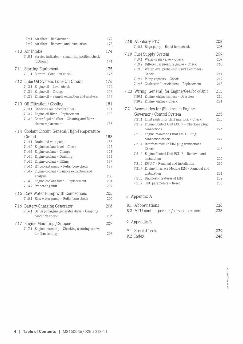
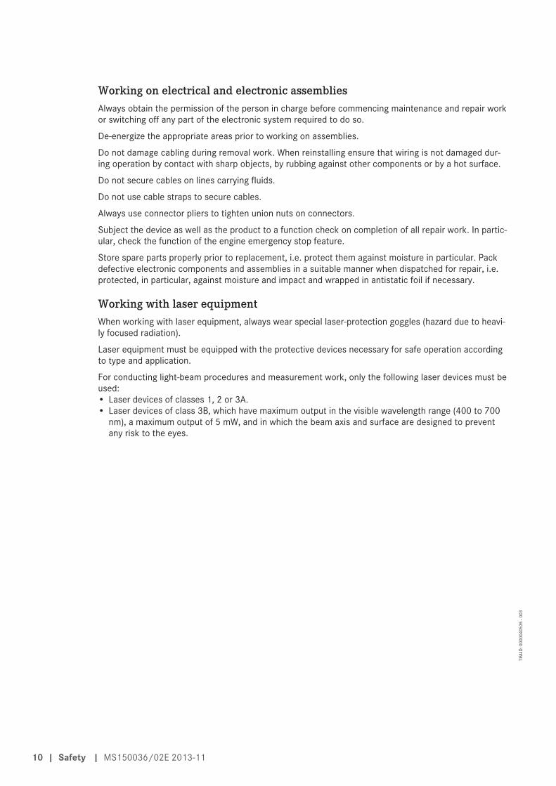
Fuel system, fuel lines with fuel pressure >1.8 barAll lines with SOLAS-compliant covers for pipe connections, according to MTU standard MTN5233, areshown.
MS150036/02E 2013-11 | General Information | 17
TIM
-ID: 0
0000
4575
1 - 0
01

1 Fuel line after LP pump
1 Fuel line to fuel filter headretainer
18 | General Information | MS150036/02E 2013-11
TIM
-ID: 0
0000
4575
1 - 0
01

1 Fuel line from fuel filterhead
1 Fuel line on HP pump
MS150036/02E 2013-11 | General Information | 19
TIM
-ID: 0
0000
4575
1 - 0
01
1 Fuel line on fuel filter head
1 Fuel line on fuel filter head
20 | General Information | MS150036/02E 2013-11
TIM
-ID: 0
0000
4575
1 - 0
01

Lube oil system, oil lines with oil pressure >1.8 barAll lines with SOLAS-compliant covers for pipe connections, according to MTU standard MTN5233, areshown.
1 Oil supply for recirculationvalve
MS150036/02E 2013-11 | General Information | 21
TIM
-ID: 0
0000
4575
1 - 0
01

1 Oil supply line on HP pump
22 | General Information | MS150036/02E 2013-11
TIM
-ID: 0
0000
4575
1 - 0
01

1 Oil supply line of HP pumpon equipment carrier
MS150036/02E 2013-11 | General Information | 23
TIM
-ID: 0
0000
4575
1 - 0
01

1 Oil supply for actuatingcylinder of turbochargerB1 exhaust flap
24 | General Information | MS150036/02E 2013-11
TIM
-ID: 0
0000
4575
1 - 0
01
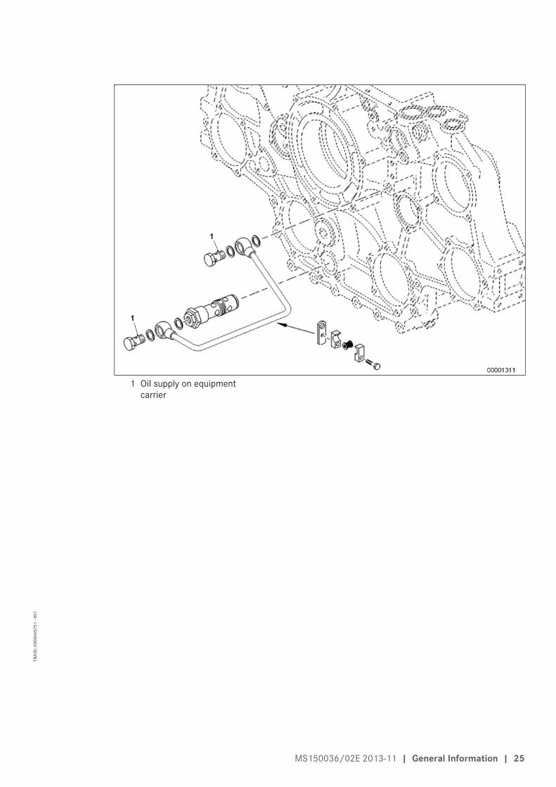
1 Oil supply on equipmentcarrier
MS150036/02E 2013-11 | General Information | 25
TIM
-ID: 0
0000
4575
1 - 0
01

Engines with horizontal air intake
1 Oil supply for actuatingcylinder of turbochargerB1 air flap
2 Oil supply for T-piece offlap control
26 | General Information | MS150036/02E 2013-11
TIM
-ID: 0
0000
4575
1 - 0
01

1 Oil supply to distributor 2 Oil return
MS150036/02E 2013-11 | General Information | 27
TIM
-ID: 0
0000
4575
1 - 0
01
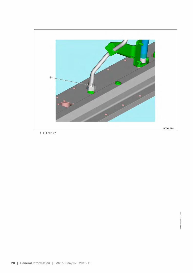
1 Oil return
28 | General Information | MS150036/02E 2013-11
TIM
-ID: 0
0000
4575
1 - 0
01
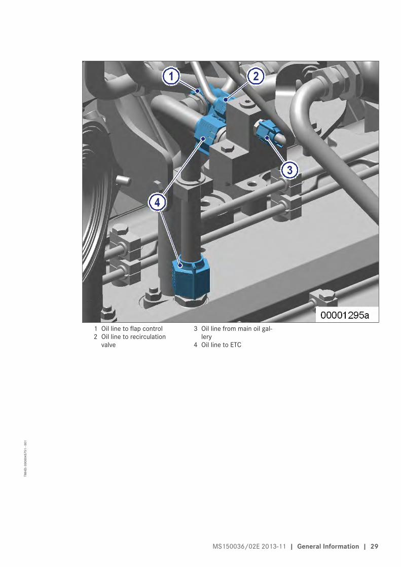
1 Oil line to flap control2 Oil line to recirculation
valve
3 Oil line from main oil gal-lery
4 Oil line to ETC
MS150036/02E 2013-11 | General Information | 29
TIM
-ID: 0
0000
4575
1 - 0
01
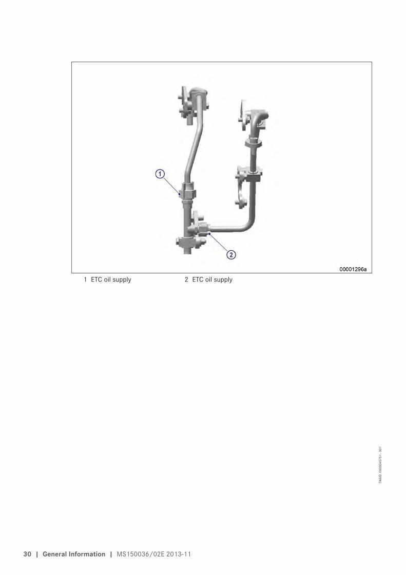
1 ETC oil supply 2 ETC oil supply
30 | General Information | MS150036/02E 2013-11
TIM
-ID: 0
0000
4575
1 - 0
01
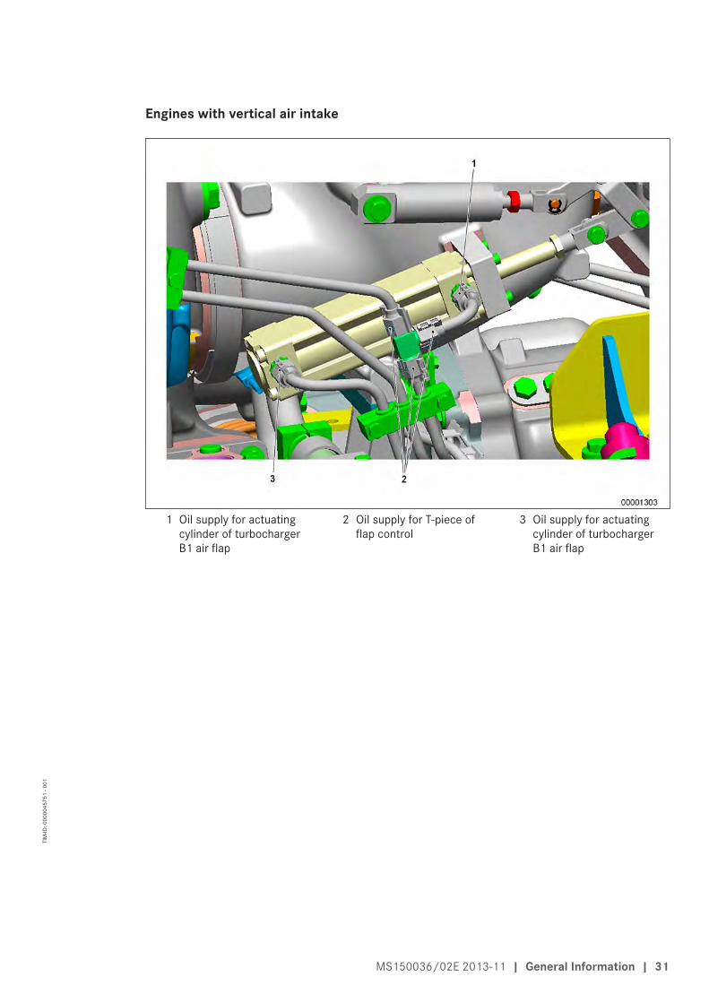
Engines with vertical air intake
1 Oil supply for actuatingcylinder of turbochargerB1 air flap
2 Oil supply for T-piece offlap control
3 Oil supply for actuatingcylinder of turbochargerB1 air flap
MS150036/02E 2013-11 | General Information | 31
TIM
-ID: 0
0000
4575
1 - 0
01

1 Oil supply to distributor offlap control, B-side
1 Oil lines for B-side flapcontrol from main oil gal-lery
2 Oil lines for B-side flapcontrol to main oil gallery
32 | General Information | MS150036/02E 2013-11
TIM
-ID: 0
0000
4575
1 - 0
01
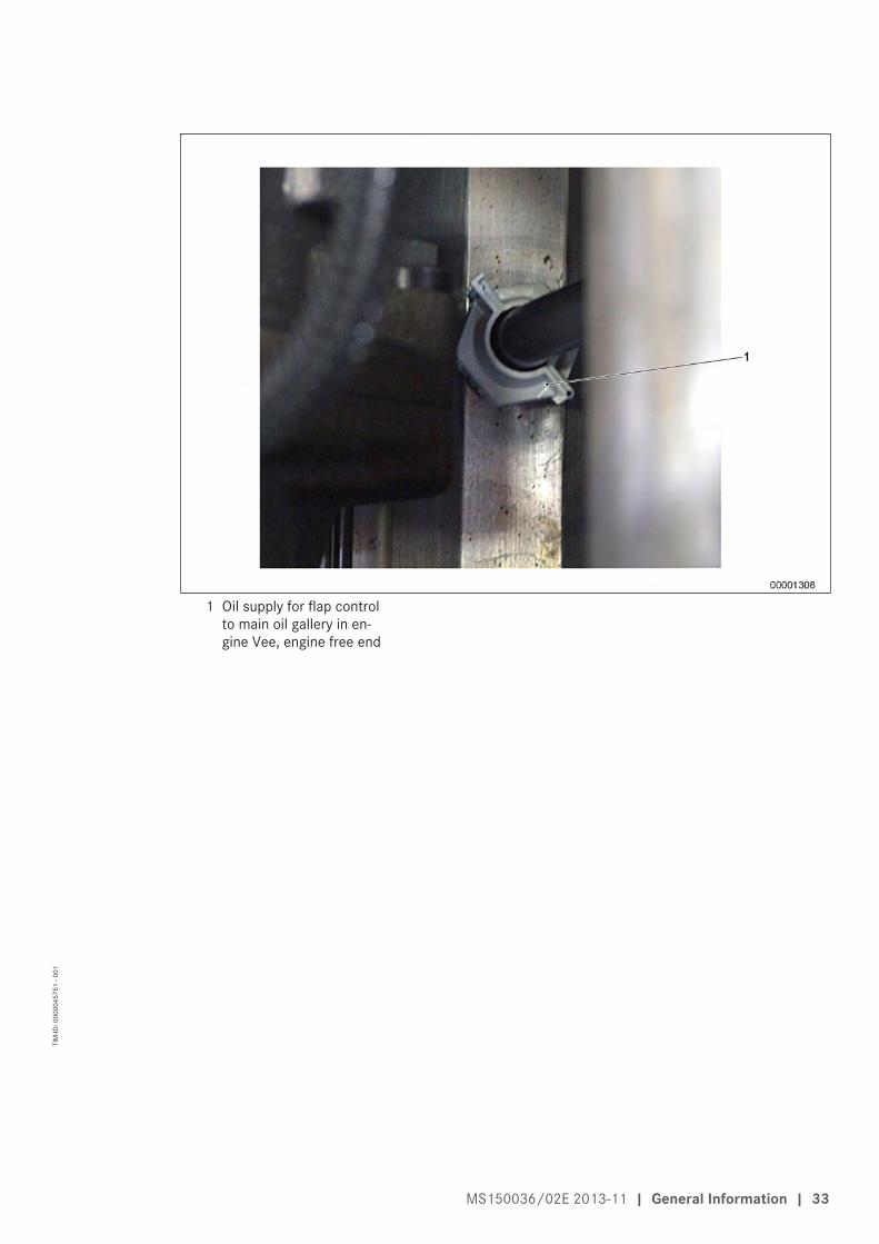
1 Oil supply for flap controlto main oil gallery in en-gine Vee, engine free end
MS150036/02E 2013-11 | General Information | 33
TIM
-ID: 0
0000
4575
1 - 0
01

1 Turbocharger oil supplyconnection to main oil gal-lery in engine Vee
34 | General Information | MS150036/02E 2013-11
TIM
-ID: 0
0000
4575
1 - 0
01

1 Oil supply on distributionpoint of turbocharger oilsupply on engine free end
1 Cover on oil filter cartridge
MS150036/02E 2013-11 | General Information | 35
TIM
-ID: 0
0000
4575
1 - 0
01
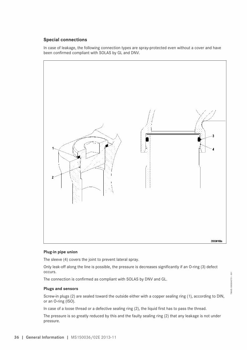
Special connectionsIn case of leakage, the following connection types are spray-protected even without a cover and havebeen confirmed compliant with SOLAS by GL and DNV.
Plug-in pipe unionThe sleeve (4) covers the joint to prevent lateral spray.
Only leak-off along the line is possible, the pressure is decreases significantly if an O-ring (3) defectoccurs.
The connection is confirmed as compliant with SOLAS by DNV and GL.
Plugs and sensorsScrew-in plugs (2) are sealed toward the outside either with a copper sealing ring (1), according to DIN,or an O-ring (ISO).
In case of a loose thread or a defective sealing ring (2), the liquid first has to pass the thread.
The pressure is so greatly reduced by this and the faulty sealing ring (2) that any leakage is not underpressure.
36 | General Information | MS150036/02E 2013-11
TIM
-ID: 0
0000
4575
1 - 0
01

HP connections
1 Jacket pipe2 HP fuel line3 O-ring4 Union nut5 Recess for O-ring6 Thrust ring7 Leakage overflow bore
8 Thrust ring9 Union nut
10 Union nut11 Connecting piece12 Snap ring13 Thrust ring14 Compensating disks
15 Union nut16 Thrust ring17 HP line outer pipe18 Internal pipe of HP line19 Ball-type seal area20 Leak-fuel connection
HP connectionsThe HP fuel line is sealed by the thrust ring (8).
If leakage in the area of the thrust ring (8) or the HP line (5) occurs, the emerging fuel is routed to theleakage chamber.
The leaking fuel is drained off without pressure via the leakage overflow-bore (7). The leakage chamberis sealed toward the outside by the O-rings (3).
This prevents leakage egress.
The connection is confirmed as compliant with SOLAS by DNV and GL.
MS150036/02E 2013-11 | General Information | 37
TIM
-ID: 0
0000
4575
1 - 0
01

2.3 Engine layout
Engines with remote heat exchanger and horizontal air intake
1 Engine management andmonitoring
2 Oil cooler3 Centrifugal oil filter4 Crankcase breather5 Dry-type air filter6 Exhaust turbocharger7 Exhaust outlet8 Air pipe to charge-air cool-
er9 Charge-air cooler
10 Recirculation line11 Exhaust manifold12 Engine mounts13 Charge-air line14 Oil pan15 Oil filler neck16 Crankcase17 Cylinder head18 Fuel filter
19 Battery-charging generator20 HP fuel pump21 Oil filter22 Bilge pump (option)23 Coolant outlet to remote
cooling system24 Coolant inlet from remote
cooling systemKGS Free end
38 | General Information | MS150036/02E 2013-11
TIM
-ID: 0
0000
0999
0 - 0
06

Engines with engine-mounted heat exchanger and horizontal air intake
1 Raw-water outlet2 Engine management and
monitoring3 Plate-core heat exchanger4 Oil cooler5 Coolant expansion tank6 Centrifugal oil filter7 Crankcase breather8 Dry-type air filter9 Exhaust turbocharger
10 Exhaust outlet11 Air pipe to charge-air cool-
er12 Recirculation line13 Exhaust manifold14 Charge-air cooler15 Charge-air line16 Engine mounts17 Oil pan18 Oil filler neck
19 Cylinder head20 Crankcase21 Fuel filter22 Battery-charging generator23 HP fuel pump24 Oil filter25 Bilge pump (option)26 Raw-water inlet
KGS Free end
MS150036/02E 2013-11 | General Information | 39
TIM
-ID: 0
0000
0999
0 - 0
06
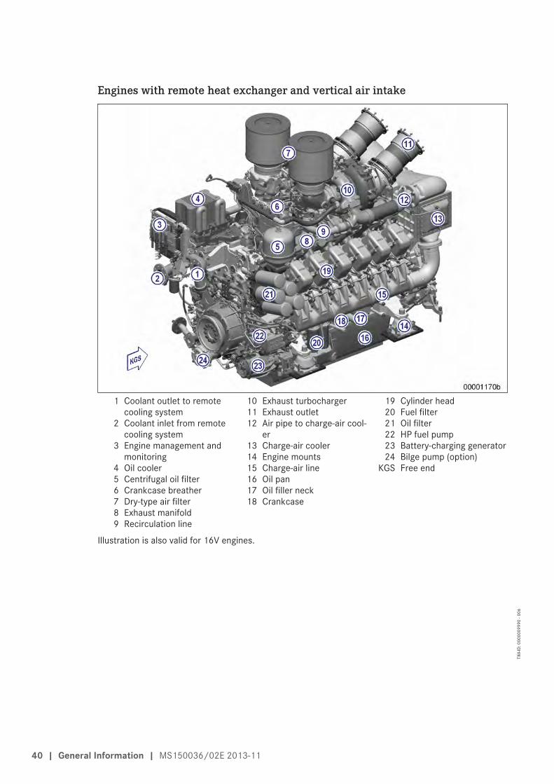
Engines with remote heat exchanger and vertical air intake
1 Coolant outlet to remotecooling system
2 Coolant inlet from remotecooling system
3 Engine management andmonitoring
4 Oil cooler5 Centrifugal oil filter6 Crankcase breather7 Dry-type air filter8 Exhaust manifold9 Recirculation line
10 Exhaust turbocharger11 Exhaust outlet12 Air pipe to charge-air cool-
er13 Charge-air cooler14 Engine mounts15 Charge-air line16 Oil pan17 Oil filler neck18 Crankcase
19 Cylinder head20 Fuel filter21 Oil filter22 HP fuel pump23 Battery-charging generator24 Bilge pump (option)
KGS Free end
Illustration is also valid for 16V engines.
40 | General Information | MS150036/02E 2013-11
TIM
-ID: 0
0000
0999
0 - 0
06

Engines with engine-mounted heat exchanger and vertical air intake
1 Raw-water outlet2 Engine management and
monitoring3 Oil cooler4 Plate-core heat exchanger5 Coolant expansion tank6 Centrifugal oil filter7 Crankcase breather8 Dry-type air filter9 Exhaust manifold
10 Recirculation line11 Exhaust turbocharger12 Exhaust outlet13 Air pipe to charge-air cool-
er14 Charge-air cooler15 Charge-air line16 Engine mounts17 Oil pan18 Oil filler neck
19 Crankcase20 Cylinder head21 Fuel filter22 Oil filter23 HP fuel pump24 Battery-charging generator25 Bilge pump (option)26 Raw-water inlet
KGS Free end
Illustration is also valid for 16V engines.
Engine model designationKey to the engine model designations 12/16V 4000 Mxy z12, 16 Number of cylindersV Cylinder arrangement: V-engine4000 SeriesM Application (M= Marine)x Application load profile (0, 1, 2, 3...9)y Design index (0, 1, 2, 3...9)z R (power / speed reduction)
L (enhanced power / speed)S (60 Hz)F (50 Hz)
MS150036/02E 2013-11 | General Information | 41
TIM
-ID: 0
0000
0999
0 - 0
06

2.4 Sensors, actuators and injectors on 12V engines – Overview
Engines with vertical air intake, remote heat exchanger
12 V 4000 M engine, left engine side
1 B49/Y26 (charge-air tem-perature before recircula-tion valve)/(recirculationvalve A)
2 B3 (intake air temperature)3 B44.1 (turbocharger A
speed)
4 B10 (charge-air pressure)5 B34.3 (fuel pressure be-
fore filter) (only if supple-mentary fuel filter is fitted)
6 B34.2 (fuel pressure be-fore filter)
7 B34.1 (fuel pressure afterfilter)
8 F46 (leak fuel level)
42 | General Information | MS150036/02E 2013-11
TIM
-ID: 0
0000
1294
1 - 0
03

12 V 4000 M engine, free end
1 B7 (lube oil temperature)2 B5.3 (lube-oil pressure be-
fore filter)3 B5.1 (lube-oil pressure af-
ter filter)
4 B33 (fuel temperature incommon rail)
5 B48 (fuel pressure in com-mon rail)
6 B1 (camshaft speed)
7 B54 (oil refill pump pres-sure) (optional)
8 B6.2 (coolant tempera-ture) (optional)
9 B6 (coolant temperature)
MS150036/02E 2013-11 | General Information | 43
TIM
-ID: 0
0000
1294
1 - 0
03

12 V 4000 M engine, right engine side
1 B44.2 (turbocharger Bspeed)
2 Y27 (turbocharger controlvalve)
3 B16 (coolant pressure)4 B9 (charge-air tempera-
ture)
44 | General Information | MS150036/02E 2013-11
TIM
-ID: 0
0000
1294
1 - 0
03
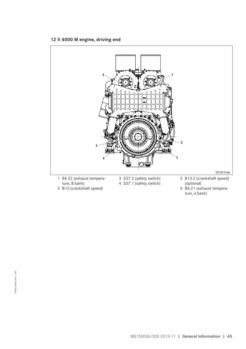
12 V 4000 M engine, driving end
1 B4.22 (exhaust tempera-ture, B bank)
2 B13 (crankshaft speed)
3 S37.2 (safety switch)4 S37.1 (safety switch)
5 B13.2 (crankshaft speed)(optional)
6 B4.21 (exhaust tempera-ture, a bank)
MS150036/02E 2013-11 | General Information | 45
TIM
-ID: 0
0000
1294
1 - 0
03
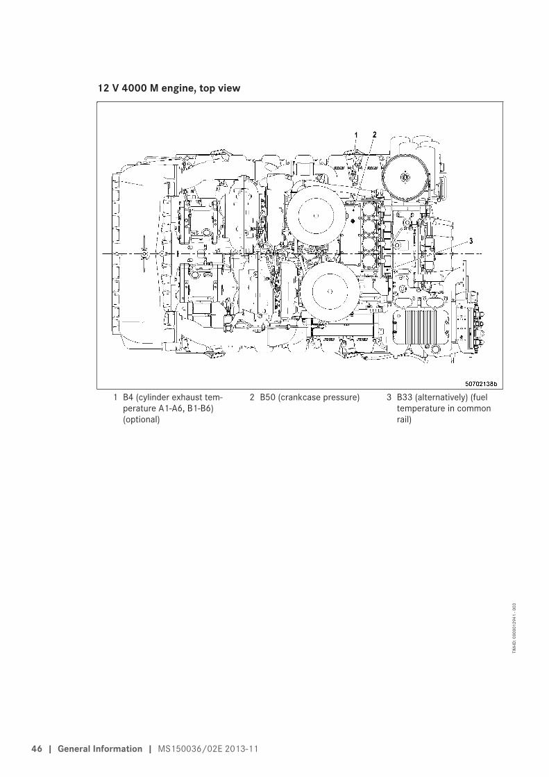
12 V 4000 M engine, top view
1 B4 (cylinder exhaust tem-perature A1-A6, B1-B6)(optional)
2 B50 (crankcase pressure) 3 B33 (alternatively) (fueltemperature in commonrail)
46 | General Information | MS150036/02E 2013-11
TIM
-ID: 0
0000
1294
1 - 0
03

Engines with vertical air intake, engine-mounted heat exchanger
12 V 4000 M engine, left engine side
1 B49/Y26 (charge-air tem-perature before recircula-tion valve)/(recirculationvalve A)
2 B3 (intake air temperature)3 B44.1 (turbocharger A
speed)
4 B10 (charge-air pressure)5 B34.3 (fuel pressure be-
fore filter) (only if supple-mentary fuel filter is fitted)
6 B34.2 (fuel pressure be-fore filter)
7 B34.1 (fuel pressure afterfilter)
8 F46 (leak fuel level)
MS150036/02E 2013-11 | General Information | 47
TIM
-ID: 0
0000
1294
1 - 0
03
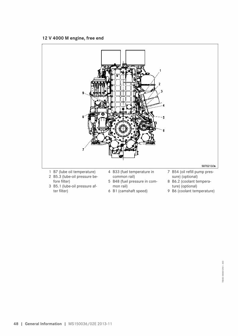
12 V 4000 M engine, free end
1 B7 (lube oil temperature)2 B5.3 (lube-oil pressure be-
fore filter)3 B5.1 (lube-oil pressure af-
ter filter)
4 B33 (fuel temperature incommon rail)
5 B48 (fuel pressure in com-mon rail)
6 B1 (camshaft speed)
7 B54 (oil refill pump pres-sure) (optional)
8 B6.2 (coolant tempera-ture) (optional)
9 B6 (coolant temperature)
48 | General Information | MS150036/02E 2013-11
TIM
-ID: 0
0000
1294
1 - 0
03

12 V 4000 M engine, right engine side
1 B44.2 (turbocharger Bspeed)
2 Y27 (turbocharger controlvalve)
3 B16 (coolant pressure)4 B21 (raw-water pressure)
(optional)
5 B9 (charge-air tempera-ture)
MS150036/02E 2013-11 | General Information | 49
TIM
-ID: 0
0000
1294
1 - 0
03

12 V 4000 M engine, driving end
1 B4.22 (exhaust tempera-ture, B bank)
2 B13 (crankshaft speed)
3 S37.2 (safety switch)4 S37.1 (safety switch)
5 B13.2 (crankshaft speed)(optional)
6 B4.21 (exhaust tempera-ture, a bank)
50 | General Information | MS150036/02E 2013-11
TIM
-ID: 0
0000
1294
1 - 0
03

12 V 4000 M engine, top view
1 B4 (cylinder exhaust tem-perature A1-A6, B1-B6)(optional)
2 B50 (crankcase pressure)
3 B33 (alternatively) (fueltemperature in commonrail)
4 F33 (coolant level)
MS150036/02E 2013-11 | General Information | 51
TIM
-ID: 0
0000
1294
1 - 0
03

2.5 Sensors, actuators and injectors on 16V engines – Overview
Engines with horizontal air intake, remote heat exchanger
16V 4000 M engine, left engine side
1 B50 (crankcase pressure)2 B3 (intake air temperature)3 B44.1 (turbocharger A
speed)
4 B10 (charge-air pressure)5 B34.3 (fuel pressure be-
fore filter) (only if supple-mentary fuel filter is fitted)
6 B34.2 (fuel pressure be-fore filter)
7 B34.1 (fuel pressure afterfilter)
8 F46 (leak fuel level)
52 | General Information | MS150036/02E 2013-11
TIM
-ID: 0
0000
1844
5 - 0
03

16V 4000 M engine, free end
1 B7 (lube oil temperature)2 B5.3 (lube oil pressure be-
fore filter)3 B5.1 (lube oil pressure af-
ter filter)
4 B33 (fuel temperature incommon rail)
5 B48 (fuel pressure in com-mon rail)
6 B1 (camshaft speed)
7 B54 (oil refill pump pres-sure) (optional)
8 B6.2 (coolant tempera-ture) (optional)
9 B6 (coolant temperature)
MS150036/02E 2013-11 | General Information | 53
TIM
-ID: 0
0000
1844
5 - 0
03
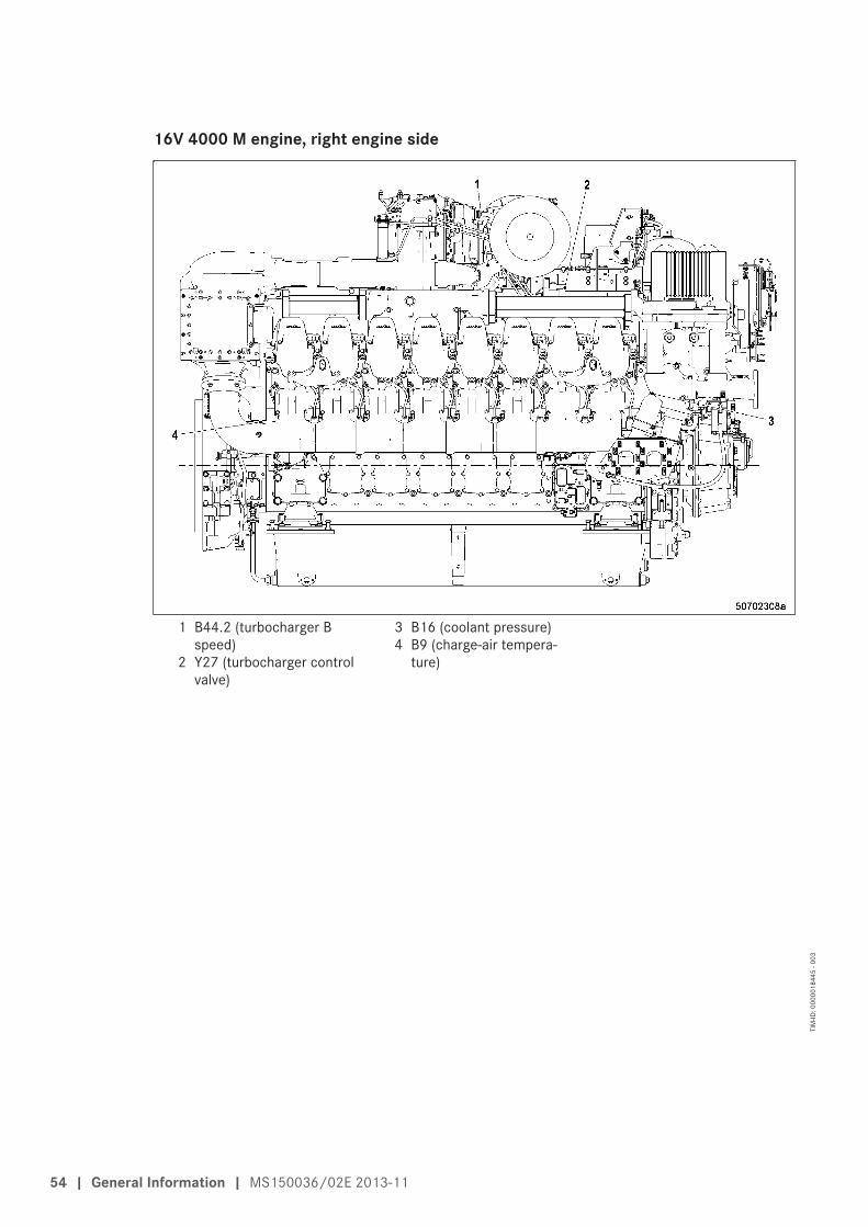
16V 4000 M engine, right engine side
1 B44.2 (turbocharger Bspeed)
2 Y27 (turbocharger controlvalve)
3 B16 (coolant pressure)4 B9 (charge-air tempera-
ture)
54 | General Information | MS150036/02E 2013-11
TIM
-ID: 0
0000
1844
5 - 0
03

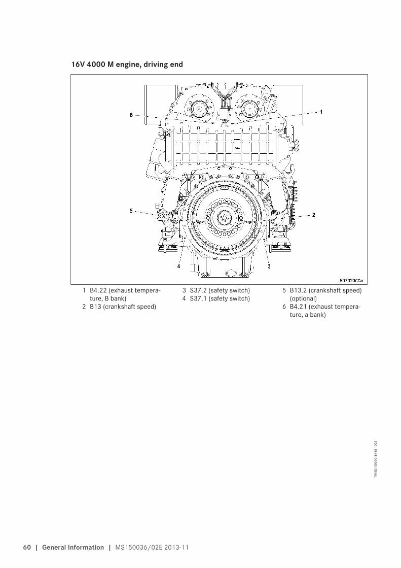
16V 4000 M engine, driving end
1 B4.22 (exhaust tempera-ture, B bank)
2 B13 (crankshaft speed)
3 S37.2 (safety switch)4 S37.1 (safety switch)
5 B13.2 (crankshaft speed)(optional)
6 B4.21 (exhaust tempera-ture, a bank)
MS150036/02E 2013-11 | General Information | 55
TIM
-ID: 0
0000
1844
5 - 0
03

16V 4000 M engine, engine top
1 B49/Y26 (charge-air tem-perature before recircula-tion valve)/(recirculationvalve A)
2 B4 (cylinder exhaust tem-perature A1-A6, B1-B8)(optional)
3 B33 (alternatively) (fueltemperature in commonrail)
56 | General Information | MS150036/02E 2013-11
TIM
-ID: 0
0000
1844
5 - 0
03

Engines with horizontal air intake, engine-mounted heat exchanger
16V 4000 M engine, left engine side
1 B50 (crankcase pressure)2 B49/Y26 (charge-air tem-
perature before recircula-tion valve)/(recirculationvalve A)
3 B44.1 (turbocharger Aspeed)
4 B3 (intake air temperature)5 B10 (charge-air pressure)6 B34.3 (fuel pressure be-
fore filter) (only if supple-mentary fuel filter is fitted)
7 B34.2 (fuel pressure be-fore filter)
8 B34.1 (fuel pressure afterfilter)
9 F46 (leak fuel level)
MS150036/02E 2013-11 | General Information | 57
TIM
-ID: 0
0000
1844
5 - 0
03

16V 4000 M engine, free end
1 B7 (lube oil temperature)2 B5.3 (lube oil pressure be-
fore filter)3 B5.1 (lube oil pressure af-
ter filter)
4 B33 (fuel temperature incommon rail)
5 B48 (fuel pressure in com-mon rail)
6 B1 (camshaft speed)
7 B54 (oil refill pump pres-sure) (optional)
8 B6.2 (coolant tempera-ture) (optional)
9 B6 (coolant temperature)
58 | General Information | MS150036/02E 2013-11
TIM
-ID: 0
0000
1844
5 - 0
03

16V 4000 M engine, right engine side
1 B44.2 (turbocharger Bspeed)
2 Y27 (turbocharger controlvalve)
3 B16 (coolant pressure)4 B21 (raw-water pressure)
(optional)
5 B9 (charge-air tempera-ture)
MS150036/02E 2013-11 | General Information | 59
TIM
-ID: 0
0000
1844
5 - 0
03
16V 4000 M engine, driving end
1 B4.22 (exhaust tempera-ture, B bank)
2 B13 (crankshaft speed)
3 S37.2 (safety switch)4 S37.1 (safety switch)
5 B13.2 (crankshaft speed)(optional)
6 B4.21 (exhaust tempera-ture, a bank)
60 | General Information | MS150036/02E 2013-11
TIM
-ID: 0
0000
1844
5 - 0
03

16V 4000 M engine, engine top
1 B4 (cylinder exhaust tem-perature A1-A6, B1-B8)(optional)
2 B33 (alternatively) (fueltemperature in commonrail)
3 F33 (coolant level)
MS150036/02E 2013-11 | General Information | 61
TIM
-ID: 0
0000
1844
5 - 0
03

Engines with vertical air intake, remote heat exchanger
16V 4000 M engine, left engine side
1 B50 (crankcase pressure)2 B49/Y26 (charge-air tem-
perature before recircula-tion valve)/(recirculationvalve A)
3 B3 (intake air temperature)
4 B44.1 (turbocharger Aspeed)
5 B10 (charge-air pressure)6 B34.3 (fuel pressure be-
fore filter) (only if supple-mentary fuel filter is fitted)
7 B34.2 (fuel pressure be-fore filter)
8 B34.1 (fuel pressure afterfilter)
9 F46 (leak fuel level)
62 | General Information | MS150036/02E 2013-11
TIM
-ID: 0
0000
1844
5 - 0
03

16V 4000 M engine, free end
1 B7 (lube oil temperature)2 B5.3 (lube-oil pressure be-
fore filter)3 B5.1 (lube-oil pressure af-
ter filter)
4 B33 (fuel temperature incommon rail)
5 B48 (fuel pressure in com-mon rail)
6 B1 (camshaft speed)
7 B54 (oil refill pump pres-sure) (optional)
8 B6.2 (coolant tempera-ture) (optional)
9 B6 (coolant temperature)
MS150036/02E 2013-11 | General Information | 63
TIM
-ID: 0
0000
1844
5 - 0
03

16V 4000 M engine, right engine side
1 B44.2 (turbocharger Bspeed)
2 Y27 (turbocharger controlvalve)
3 B16 (coolant pressure)4 B9 (charge-air tempera-
ture)
64 | General Information | MS150036/02E 2013-11
TIM
-ID: 0
0000
1844
5 - 0
03

16V 4000 M engine, driving end
1 B4.22 (exhaust tempera-ture, B bank)
2 B13 (crankshaft speed)
3 S37.2 (safety switch)4 S37.1 (safety switch)
5 B13.2 (crankshaft speed)(optional)
6 B4.21 (exhaust tempera-ture, a bank)
MS150036/02E 2013-11 | General Information | 65
TIM
-ID: 0
0000
1844
5 - 0
03

16V 4000 M engine, engine top
1 B4 (cylinder exhaust tem-perature A1-A6, B1-B8)(optional)
2 B33 (alternatively) (fueltemperature in commonrail)
66 | General Information | MS150036/02E 2013-11
TIM
-ID: 0
0000
1844
5 - 0
03

Engines with vertical air intake, engine-mounted heat exchanger
16V 4000 M engine, left engine side
1 B50 (crankcase pressure)2 B49/Y26 (charge-air tem-
perature before recircula-tion valve)/(recirculationvalve A)
3 B3 (intake air temperature)
4 B44.1 (turbocharger Aspeed)
5 B10 (charge-air pressure)6 B34.3 (fuel pressure be-
fore filter) (only if supple-mentary fuel filter is fitted)
7 B34.2 (fuel pressure be-fore filter)
8 B34.1 (fuel pressure afterfilter)
9 F46 (leak fuel level)
MS150036/02E 2013-11 | General Information | 67
TIM
-ID: 0
0000
1844
5 - 0
03
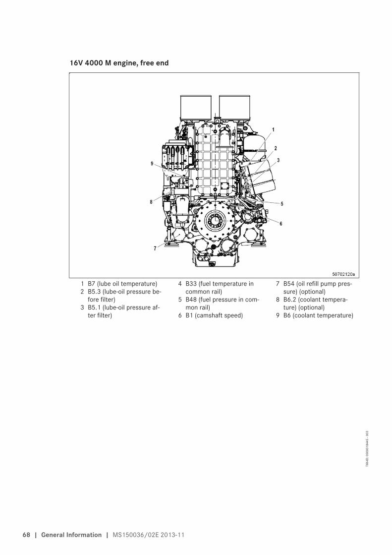
16V 4000 M engine, free end
1 B7 (lube oil temperature)2 B5.3 (lube-oil pressure be-
fore filter)3 B5.1 (lube-oil pressure af-
ter filter)
4 B33 (fuel temperature incommon rail)
5 B48 (fuel pressure in com-mon rail)
6 B1 (camshaft speed)
7 B54 (oil refill pump pres-sure) (optional)
8 B6.2 (coolant tempera-ture) (optional)
9 B6 (coolant temperature)
68 | General Information | MS150036/02E 2013-11
TIM
-ID: 0
0000
1844
5 - 0
03

16V 4000 M engine, right engine side
1 B44.2 (turbocharger Bspeed)
2 Y27 (turbocharger controlvalve)
3 B16 (coolant pressure)4 B21 (raw-water pressure)
(optional)
5 B9 (charge-air tempera-ture)
MS150036/02E 2013-11 | General Information | 69
TIM
-ID: 0
0000
1844
5 - 0
03

16V 4000 M engine, driving end
1 B4.22 (exhaust tempera-ture, B bank)
2 B13 (crankshaft speed)
3 S37.2 (safety switch)4 S37.1 (safety switch)
5 B13.2 (crankshaft speed)(optional)
6 B4.21 (exhaust tempera-ture, a bank)
70 | General Information | MS150036/02E 2013-11
TIM
-ID: 0
0000
1844
5 - 0
03

16V 4000 M engine, engine top
1 B4 (cylinder exhaust tem-perature A1-A6, B1-B8)(optional)
2 B33 (alternatively) (fueltemperature in commonrail)
3 F33 (coolant level)
MS150036/02E 2013-11 | General Information | 71
TIM
-ID: 0
0000
1844
5 - 0
03

3 Technical Data
3.1 12V 4000 M53R engine dataExplanation:
DL Ref. value: Continuous powerBL Ref. value: Fuel stop powerA Design valueG Guaranteed valuer Guideline valueL Limit up to which the engine can be operated without changes, e.g. power settingN Not yet defined value- Not applicable
X Applicable* Not yet verified value
ENGINE DATA
Engine model 12V 4000 M53REngine-mountedheat exchanger
12V 4000 M53RRemote heat ex-
changerApplication group 1A 1A 1A 1A
Intake air temperature °C 25 45 25 45
Charge air coolant temperature °C - - - -
Raw water inlet temperature °C 25 32 25 32
Barometric pressure mbar 1000 1000 1000 1000
Site altitude above sea level M 100 100 100 100
POWER-RELATED DATA (power ratings are net brake power as per ISO 3046)
Engine model 12V 4000 M53REngine-mountedheat exchanger
12V 4000 M53RRemote heat ex-
changerRated engine speed A rpm 1600 1600 1600 1600
Fuel stop power ISO 3046 A kW 1140 1140 1140 1140
GENERAL CONDITIONS (for maximum power)
Engine model 12V 4000 M53REngine-mountedheat exchanger
12V 4000 M53RRemote heat ex-
changerIntake depression (new filter) A mbar 15 15 15 15
Intake depression, max. L mbar 30 30 30 30
72 | Technical Data | MS150036/02E 2013-11
TIM
-ID: 0
0000
1078
6 - 0
02

MODEL RELATED DATA (basic design)
Engine model 12V 4000 M53REngine-mountedheat exchanger
12V 4000 M53RRemote heat ex-
changerCylinder arrangement: V angle Degrees
(°)90 90 90 90
Bore mm 170 170 170 170
Stroke mm 210 210 210 210
Displacement, cylinder Liters 4.77 4.77 4.77 4.77
Displacement, total Liters 57.2 57.2 57.2 57.2
Number of inlet valves per cylinder 2 2 2 2
Number of exhaust valves per cylinder 2 2 2 2
RAW WATER CIRCUIT (open circuit)
Engine model 12V 4000 M53REngine-mountedheat exchanger
12V 4000 M53RRemote heat ex-
changerRaw water pump: Inlet pressure, min. L bar -0.4 -0.4 -- --
Raw water pump: Inlet pressure, max. L bar 1.0 1.0 -- --
Pressure loss in off-engine raw-water sys-tem, max.
L bar 1.0 1.0 -- --
LUBE OIL SYSTEM
Engine model 12V 4000 M53REngine-mountedheat exchanger
12V 4000 M53RRemote heat ex-
changerLube oil operating temperature before en-gine, from
r °C 81 82 81 82
Lube oil operating temperature before en-gine, to
r °C 89 90 89 90
Lube oil operating pressure before engine,from
r bar 5.1 5.1 5.1 5.1
Lube oil operating pressure before engine,to
r bar 6.1 6.1 6.1 6.1
Lube oil operating pressure (low idle)(meas. point: before engine)
r bar 2.5 2.5 2.5 2.5
FUEL SYSTEM
Engine model 12V 4000 M53REngine-mountedheat exchanger
12V 4000 M53RRemote heat ex-
changerFuel pressure at engine inlet connection,min. (when engine is starting)
L bar -0.1 -0.1 -0.1 -0.1
Fuel pressure at engine inlet connection,min. (when engine is running),
L bar -0.3 -0.3 -0.3 -0.3
Fuel pressure at engine inlet connection,max. (when engine is starting)
L bar 1.5 1.5 1.5 1.5
MS150036/02E 2013-11 | Technical Data | 73
TIM
-ID: 0
0000
1078
6 - 0
02

GENERAL OPERATING DATA
Engine model 12V 4000 M53REngine-mountedheat exchanger
12V 4000 M53RRemote heat ex-
changerFiring speed, from r rpm 80 80 80 80
Firing speed, to r rpm 120 120 120 120
STARTER (electric)
Engine model 12V 4000 M53REngine-mountedheat exchanger
12V 4000 M53RRemote heat ex-
changerRated starter voltage (standard design) r V= 24 24 24 24
STARTER (pneumatic / hydraulic)
Engine model 12V 4000 M53REngine-mountedheat exchanger
12V 4000 M53RRemote heat ex-
changerStarting air pressure before starter motor,min.
r bar 8 8 8 8
Starting air pressure before starter motor,max.
r bar 10 10 10 10
INCLINATIONS, STANDARD OIL SYSTEM (Reference: waterline)
Engine model 12V 4000 M53REngine-mountedheat exchanger
12V 4000 M53RRemote heat ex-
changerLongitudinal inclination, continuous max.,driving end down (Option: max. operatinginclinations)
L Degrees(°)
15 15 15 15
Longitudinal inclination, temporary max.driving end down (option: max. operatinginclinations)
L Degrees(°)
22.5 22.5 22.5 22.5
Longitudinal inclination, continuous max.driving end up (option: max. operating in-clinations)
L Degrees(°)
10 10 10 10
Transverse inclination continuous max.(Option: max. operating inclinations)
L Degrees(°)
22.5 22.5 22.5 22.5
CAPACITIES
Engine model 12V 4000 M53REngine-mountedheat exchanger
12V 4000 M53RRemote heat ex-
changerEngine coolant capacity, engine side (withcooling equipment)
r Liters 305 305 -- --
Engine oil capacity, initial filling (standardoil system) (Option: max. operating incli-nations)
r Liters 265 265 265 265
74 | Technical Data | MS150036/02E 2013-11
TIM
-ID: 0
0000
1078
6 - 0
02

Engine model 12V 4000 M53REngine-mountedheat exchanger
12V 4000 M53RRemote heat ex-
changerOil pan capacity dipstick mark min.(standard oil system) (design: max. oper-ating inclinations)
L Liters 195 195 195 195
Oil pan capacity dipstick mark max.(standard oil system) (design: max. oper-ating inclinations)
L Liters 235 235 235 235
WEIGHTS / MAIN DIMENSIONS
Engine model 12V 4000 M53REngine-mountedheat exchanger
12V 4000 M53RRemote heat ex-
changerEngine dry weight (with mounted standardaccessories, w/o coupling)
r kg 7640 7640 7240 7240
NOISE
Engine model 12V 4000 M53REngine-mountedheat exchanger
12V 4000 M53RRemote heat ex-
changerExhaust noise, unsilenced, BL (free-fieldsound pressure level Lp, 1m distance, ISO6798, +3dB(A) tolerance)
r dB(A) 108* 108* 108* 108*
Engine surface noise with attenuated in-take noise (filter), BL, (free-field sound-pressure level Lp, 1m distance, ISO6798+2dB(A) tolerance)
r dB(A) 102* 102* 102* 102*
MS150036/02E 2013-11 | Technical Data | 75
TIM
-ID: 0
0000
1078
6 - 0
02

3.2 16V 4000 M53R engine dataExplanation:
DL Ref. value: Continuous powerBL Ref. value: Fuel stop powerA Design valueG Guaranteed valuer Guideline valueL Limit up to which the engine can be operated without changes, e.g. power settingN Not yet defined value- Not applicable
X Applicable
Heat exchangerengine-mounted
Heat exchangerremote
Application group 1A 1A 1A 1A
Intake air temperature °C 25 45 25 45
Charge air coolant temperature °C - - - -
Raw water inlet temperature °C 25 32 25 32
Barometric pressure mbar 1000 1000 1000 1000
Site altitude above sea level M 100 100 100 100
POWER-RELATED DATA (power ratings are net brake power as per ISO 3046)
Heat exchangerengine-mounted
Heat exchangerremote
Rated engine speed A rpm 1600 1600 1600 1600
Fuel stop power ISO 3046 A kW 1520 1520 1520 1520
GENERAL CONDITIONS (for maximum power)
Heat exchangerengine-mounted
Heat exchangerremote
Intake depression (new filter) A mbar 15 15 15 15
Intake depression, max. L mbar 30 30 30 30
MODEL RELATED DATA (basic design)
Heat exchangerengine-mounted
Heat exchangerremote
Cylinder arrangement: V angle Degrees(°)
90 90 90 90
Bore mm 170 170 170 170
Stroke mm 210 210 210 210
Displacement, cylinder Liters 4.77 4.77 4.77 4.77
Displacement, total Liters 76.3 76.3 76.3 76.3
Number of inlet valves per cylinder 2 2 2 2
Number of exhaust valves per cylinder 2 2 2 2
76 | Technical Data | MS150036/02E 2013-11
TIM
-ID: 0
0000
1085
4 - 0
02

RAW WATER CIRCUIT (open circuit)
Heat exchangerengine-mounted
Heat exchangerremote
Raw water pump: Inlet pressure, min. L bar -0.4 -0.4 -- --
Raw water pump: Inlet pressure, max. L bar 1.0 1.0 -- --
Pressure loss in off-engine raw-water sys-tem, max.
L bar 1.0 1.0 -- --
LUBE OIL SYSTEM
Heat exchangerengine-mounted
Heat exchangerremote
Lube oil operating temperature before en-gine, from
r °C 82 82 82 82
Lube oil operating temperature before en-gine, to
r °C 90 90 90 90
Lube oil operating pressure before engine,from
r bar 5.2 5.2 5.2 5.2
Lube oil operating pressure before engine,to
r bar 6.2 6.2 6.2 6.2
Lube oil operating pressure (low idle)(meas. point: before engine)
r bar 2.5 2.5 2.5 2.5
FUEL SYSTEM
Heat exchangerengine-mounted
Heat exchangerremote
Fuel pressure at engine inlet connection,min. (when engine is starting)
L bar -0.1 -0.1 -0.1 -0.1
Fuel pressure at engine inlet connection,min. (when engine is running),
L bar -0.3 -0.3 -0.3 -0.3
Fuel pressure at engine inlet connection,max. (when engine is starting)
L bar 1.5 1.5 1.5 1.5
Fuel supply flow, max. A Liter/min
GENERAL OPERATING DATA
Heat exchangerengine-mounted
Heat exchangerremote
Firing speed, from r rpm 80 80 80 80
Firing speed, to r rpm 120 120 120 120
STARTER (electric)
Heat exchangerengine-mounted
Heat exchangerremote
Rated starter voltage (standard design) r V= 24 24 24 24
MS150036/02E 2013-11 | Technical Data | 77
TIM
-ID: 0
0000
1085
4 - 0
02

STARTER (pneumatic / hydraulic)
Heat exchangerengine-mounted
Heat exchangerremote
Starting air pressure before starter motor,min.
r bar 8 8 8 8
Starting air pressure before starter motor,max.
r bar 9 9 9 9
INCLINATIONS, STANDARD OIL SYSTEM (Reference: waterline)
Heat exchangerengine-mounted
Heat exchangerremote
Longitudinal inclination, continuous max.,driving end down (Option: max. operatinginclinations)
L Degrees(°)
15 15 15 15
Longitudinal inclination, temporary max.driving end down (option: max. operatinginclinations)
L Degrees(°)
22.5 22.5 22.5 22.5
Longitudinal inclination, continuous max.driving end up (option: max. operating in-clinations)
L Degrees(°)
10 10 10 10
Longitudinal inclination, temporary max.driving end up (option: max. operating in-clinations)
L Degrees(°)
Transverse inclination continuous max.(Option: max. operating inclinations)
L Degrees(°)
22.5 22.5 22.5 22.5
Transverse inclination, temporary max.(option: max. operating inclinations)
L Degrees(°)
CAPACITIES
Heat exchangerengine-mounted
Heat exchangerremote
Engine coolant capacity, engine side (withcooling equipment)
r Liters 350 350 -- --
Engine oil capacity, initial filling (standardoil system) (Option: max. operating incli-nations)
r Liters 280 280 280 280
Oil change quantity max. (standard oil sys-tem) (design: max. operating inclinations)
r Liters
Oil pan capacity dipstick mark min.(standard oil system) (design: max. oper-ating inclinations)
L Liters 210 210 210 210
Oil pan capacity dipstick mark max.(standard oil system) (design: max. oper-ating inclinations)
L Liters 250 250 250 250
78 | Technical Data | MS150036/02E 2013-11
TIM
-ID: 0
0000
1085
4 - 0
02
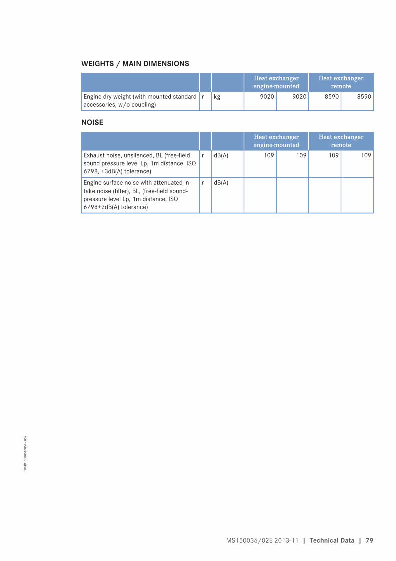
WEIGHTS / MAIN DIMENSIONS
Heat exchangerengine-mounted
Heat exchangerremote
Engine dry weight (with mounted standardaccessories, w/o coupling)
r kg 9020 9020 8590 8590
NOISE
Heat exchangerengine-mounted
Heat exchangerremote
Exhaust noise, unsilenced, BL (free-fieldsound pressure level Lp, 1m distance, ISO6798, +3dB(A) tolerance)
r dB(A) 109 109 109 109
Engine surface noise with attenuated in-take noise (filter), BL, (free-field sound-pressure level Lp, 1m distance, ISO6798+2dB(A) tolerance)
r dB(A)
MS150036/02E 2013-11 | Technical Data | 79
TIM
-ID: 0
0000
1085
4 - 0
02

3.3 Engine – Main dimensions
Engines with horizontal air intake
With remote heat exchanger
Engine model Length (A) Width (B) withoutsilencer
Width (B) with si-lencer
Height (C)
16V 4000 M53R approx. 3108 mm approx. 1690 mm approx. 1850 mm approx. 2064 mm
With engine-mounted heat exchanger
Engine model Length (A) Width (B) withoutsilencer
Width (B) with si-lencer
Height (C)
16V 4000 M53R approx. 3388 mm approx. 1690 mm approx. 1850 mm approx. 2064 mm
80 | Technical Data | MS150036/02E 2013-11
TIM
-ID: 0
0000
4575
2 - 0
01

Engines with vertical air intake
With remote heat exchanger
Engine model Length (A) Width (B) Height (C) withoutsilencer
Height (C) with si-lencer
12V 4000 M53R approx. 2628 mm approx. 1602 mm approx. 2368 mm approx. 2448 mm
16V 4000 M53R approx. 3108 mm approx. 1602 mm approx. 2361 mm approx. 2441 mm
With engine-mounted heat exchanger
Engine model Length (A) Width (B) Height (C) withoutsilencer
Height (C) with si-lencer
12V 4000 M53R approx. 2857 mm approx. 1602 mm approx. 2368 mm approx. 2448 mm
16V 4000 M53R approx. 3388 mm approx. 1602 mm approx. 2361 mm approx. 2441 mm
MS150036/02E 2013-11 | Technical Data | 81
TIM
-ID: 0
0000
4575
2 - 0
01

3.4 Firing orderCylinders Firing order12 V A1-B5-A5-B3-A3-B6-A6-B2-A2-B4-A4-B116 V A1-A7-B4-B6-A4-B8-A2-A8-B3-B5-A3-A5-B2-A6-B1-B7
82 | Technical Data | MS150036/02E 2013-11
TIM
-ID: 0
0000
2326
3 - 0
02
4 Operation
4.1 Controls
Automation system controlsRefer to automation system operating instructions
MS150036/02E 2013-11 | Operation | 83
TIM
-ID: 0
0000
1695
9 - 0
03

4.2 Putting the engine into operation after extended out-of-serviceperiods (>3 months)
Preconditions☑ Engine is stopped and starting disabled.
☑ MTU Preservation and Represervation Specifications (A001070/..) are available.
Putting the engine into operation after extended out-of-service-periods (>3months)Item TaskEngine Depreserve (→ Preservation and Represervation Specifications A001070/..).Lube oil system Check engine oil level (→ Page 176);
Preheat engine oil if required.Fuel prefilter Prime with fuel (→ Page 161)Fuel prefilter, pressuregauge
Align adjustable pointer with position of pressure indicator (→ Page 156).
HP fuel pump Only for engines without oil priming pump:Fill HP fuel pump with new engine oil (→ Page 144).
Raw-water pump (if locatedabove waterline (only appli-cable to engines with en-gine-mounted heat exchang-er or with optional remoteheat exchanger))
Prime with water (approx. 3 – 4 l).
Coolant circuit If engine is out of service for more than one year, change engine coolant(→ Page 193).
Coolant circuit Check coolant level (→ Page 192).Coolant circuit Preheat coolant with preheating unit.Engine control system Refer to automation system operating instructions.ECU Check plug connections (→ Page 226).EMU Check plug connections (→ Page 227)EIM Check plug connections (→ Page 228).
84 | Operation | MS150036/02E 2013-11
TIM
-ID: 0
0000
1009
2 - 0
05

4.3 Putting the engine into operation after scheduled out-of-service-period
Preconditions☑ Engine is stopped and starting disabled.
Putting into operationItem TaskLube oil system Check engine oil level (→ Page 176);
Preheat engine oil if required.Coolant system Check coolant level (→ Page 192).Coolant system Preheat coolant with preheating unit.Fuel prefilter Drain (→ Page 157);
Check that suction-side pressure indicated at the fuel prefilter pressuregauge is within the limit (→ Page 156).
Engine control system Refer to automation system operating instructions.ECU Check plug connections (→ Page 226).EIM Check plug connections (→ Page 228).EMU Check plug connections (→ Page 227).
MS150036/02E 2013-11 | Operation | 85
TIM
-ID: 0
0000
1065
5 - 0
04
4.4 Starting the engine
Start the engine via the automation systemRefer to automation system operating instructions
86 | Operation | MS150036/02E 2013-11
TIM
-ID: 0
0000
1752
5 - 0
03

4.5 Operational checksDANGER Rotating and moving engine parts.
Risk of crushing, danger of parts of the body being caught or pulled in!• Only run the engine at low power. Keep away from the engine's danger zone.
WARNING High level of engine noise when the engine is running.Risk of damage to hearing!• Wear ear protectors.
Operational checksItem MeasureEngine under loadEngine at nominal speed
Check engine visually for leaks and general condition; Check air pipework be-tween air filter and exhaust turbocharger for leaks and damage.Check for abnormal running noise, vibration, and exhaust color (→ Page 101).
Charge-air cooler Check condensate drain (→ Page 171).Air filter Check signal ring position of service indicator (→ Page 174).
Replace air filter (→ Page 172), if the signal ring is completely visible in theservice indicator control window.
HP fuel pump Check relief bores for fuel discharge (→ Page 145).HT coolant pump Check relief bore for oil and coolant discharge and obstructions
(→ Page 199).Fuel prefilter (optional) Check reading on differential pressure gauge (→ Page 174);
Drain water and contaminants (→ Page 159).Raw water pump (only onengines with engine-mount-ed or optional remote heatexchanger)
Check relief bore for oil and coolant discharge and obstructions(→ Page 205).
Bilge pump (optional) Check relief bore for oil and coolant discharge and obstructions(→ Page 208).
MS150036/02E 2013-11 | Operation | 87
TIM
-ID: 0
0000
1847
4 - 0
03

4.6 Tasks after extended out-of-service periods (>3 weeks)
Tasks after extended out-of-service periods (>3 weeks)Note: Operate fuel treatment system for at least 5 minutes.
1. Start up fuel treatment system (→ Page 90).2. Shut down fuel treatment system (→ Page 94).
88 | Operation | MS150036/02E 2013-11
TIM
-ID: 0
0000
0773
0 - 0
05

4.7 Checks prior to start-up
Checks prior to start-up1. Check tank and the entire pipework for cleanness. If microorganisms are detected:
a) Clean affected components.b) Disinfect affected components with biocides (→ MTU Fluids and Lubricants Specifications
A001061/..).2. Close drain valves on housing.3. Open all supply and discharge valves.4. Switch on fuel treatment system (→ Page 93).5. Check direction of rotation of pump.6. Vent bypass and fuel lines of the system.
a) Open ball valve for pressure tank.b) Open ball valve for overflow tank.c) Close ball valve at the inlet to the fuel treatment system.
Result: Bypass line is vented via the overflow tank.d) Open ball valve at the inlet to the fuel treatment system.
7. Check the fuel treatment system for leaks.Result: The fuel treatment system is ready for operation.
MS150036/02E 2013-11 | Operation | 89
TIM
-ID: 0
0000
0773
6 - 0
05

4.8 Fuel treatment system – Putting into operation
Overview of fuel treatment system
1 Pressure-free overflow2 Bypass 13 Bypass 24 Safety valve, 3 bar5 Ball valve, inlet6 Pressure gage7 Ventilation, sample extrac-
tion8 Differential pressure gage
9 Ball valve, outlet10 Check valve 700 mbar11 Check valve 5 mbar12 Return to overflow con-
tainer13 Engine14 Overflow container15 Water separator filter16 Ball valve, drain
17 Automatic water drain18 Water level electrode19 Ball valve, sample extrac-
tion, inlet20 Switchgear cabinet21 Pump22 Coarse filter23 Fuel supply from tank24 Tank
Switching on fuel treatment system1. Switch on fuel treatment system (→ Page 93).2. Check differential pressure at differential pressure gage (8). Differential pressure in a new system:
0.1 bar to 0.3 bar.Result: If no differential pressure is measured, the coalescer filter element is probably being bypassed.
1. Remove coalescer filter element (→ Page 213).2. Check sealing surfaces on coalescer filter element and in the pressure tank.
90 | Operation | MS150036/02E 2013-11
TIM
-ID: 0
0000
1577
3 - 0
06

Initial operation: HAT1. Replace fuel filter on engine (→ Page 154).
Note: Determine the suction pressure upstream of the engine-mounted fuel delivery pump.2. Install pressure gage in fuel supply line from Yard fuel system to engine.3. Switch on fuel treatment system and operate it for some minutes (→ Page 93).
Result: The fuel is drawn from tank (24), cleaned by the water separator filter (15) and then routed via overflowtank (14) back to tank (24). Water that collects in the tank is separated.
4. Start engine (→ Page 86).5. Run engine at idling speed.6. Check suction pressure (see technical data of the engine) at the engine-mounted fuel delivery pump.
Note: If the suction pressure is within the permissible limits and engine operation is satisfactory.7. Increase engine speed to 1000 rpm and monitor suction pressure.8. Check suction pressure at the engine-mounted fuel delivery pump.
Result: If the values are within the limits specified by the manufacturer, the system is ready to start filter re-placement simulation with the engine running as part of the Harbor Acceptance Tests.
Simulation of filter replacement with the engine running: HAT1. Switch on fuel treatment system (→ Page 93).2. Start engine (→ Page 86).3. Run engine at idling speed.4. Close ball valve (5) at inlet to fuel treatment system.
Result: The pressure upstream of the fuel treatment system increases until the overflow valve at the pump unitopens and fuel flows through bypass (3) and bypass (2).
5. Open ball valve (19) .Result: Fuel emerges. If no fuel emerges:
• Open ball valve (5) at inlet to fuel treatment system.• No function of bypasses (2) and (3); carry out functional test of bypasses (2) and (3) .
6. Check suction pressure (see technical data of the engine) at the fuel delivery pump.
Note: If the suction pressure is within the permissible limits and engine operation is satisfactory.7. Increase engine speed to 1000 rpm and monitor suction pressure.
Result: If all engine operating values are within the specified limits, open ball valve (5) at inlet to fuel treatmentsystem.
Simulation of power failure (emergency): HAT1. Switch on fuel treatment system (→ Page 93).2. Start engine (→ Page 86).3. Run engine at idling speed.4. Switch off pump (21) at switchgear cabinet (20).
Result: The engine-mounted fuel delivery pump draws fuel via bypass (2) directly from tank (24).5. Check suction pressure at the engine-mounted fuel delivery pump.
Note: If the suction pressure is within the permissible limits and engine operation is satisfactory.6. Increase engine speed to 1000 rpm and monitor suction pressure.
Result: If the suction pressure is within the specified limits, simulation was successful.
MS150036/02E 2013-11 | Operation | 91
TIM
-ID: 0
0000
1577
3 - 0
06

Simulation of power failure (emergency): SAT1. Switch on fuel treatment system (→ Page 93).2. Start engine (→ Page 86).3. Run engine at idling speed.4. Switch off pump (21) at switchgear cabinet (20).
Result: The engine-mounted fuel delivery pump draws fuel via bypass (2) directly from tank (24).5. Check suction pressure at the engine-mounted fuel delivery pump.
Note: If the suction pressure is within the permissible limits and engine operation is satisfactory.6. Operate engine at full load and monitor suction pressure.
Result: If the suction pressure is within the specified limits, simulation was successful.
92 | Operation | MS150036/02E 2013-11
TIM
-ID: 0
0000
1577
3 - 0
06

4.9 Fuel treatment system – Switching on
Preconditions☑ The on-board power supply is switched on.
NOTICE Risk of damage to engine/system.Risk of severe damage to property!• Before switching on, ensure that the engine/system is ready for operation.• Before switching on, ensure that all housings are closed.• Before switching on, ensure that no work is in progress anywhere on the entire system.
Fuel treatment system – Switching on1. Carry out checks prior to start-up (→ Page 89).2. Switch on master switch on switchgear cabinet.
Result: Signal lamp “Control voltage present” lights up.3. Switch on switch for pump.
Result: Signal lamp “Pump running” lights up.
MS150036/02E 2013-11 | Operation | 93
TIM
-ID: 0
0000
0773
1 - 0
06

4.10 Fuel treatment system – Shutdown
Shutting down fuel treatment system1. Press the illuminated pushbutton "Water drain" on the switch cabinet until water discharge from the
outlet stops.2. Switch off fuel treatment system.3. Close ball valve at the inlet to the fuel treatment system.4. Close ball valve at the outlet of the fuel treatment system.5. Open drain valve until pressure has escaped from fuel treatment system.
94 | Operation | MS150036/02E 2013-11
TIM
-ID: 0
0000
0773
2 - 0
05
4.11 Stopping the engine
Stopping the engine via the automation systemRefer to automation system operating instructions
MS150036/02E 2013-11 | Operation | 95
TIM
-ID: 0
0000
1752
8 - 0
04

4.12 Emergency engine stopNOTICE An emergency stop causes extreme stress to the engine plant.
Risk of overheating, damage to components!• Initiate emergency stop only in emergency situations.
Emergency stop1. Refer to automation system operating instructions.2. Follow instructions.
96 | Operation | MS150036/02E 2013-11
TIM
-ID: 0
0000
1753
0 - 0
05

4.13 After stopping the engine
Preconditions☑ MTU Preservation and Re-preservation Specifications (A001070/..) are available.
After stopping the engineItem MeasureCoolant circuit Drain coolant (→ Page 194) if:
• freezing temperatures are expected and the engine is to remain out ofservice for an extended period, but engine coolant has no antifreezeadditive;
• the engine room is not heated;• the coolant is not kept at a suitable temperature;• the antifreeze concentration is insufficient for the engine-room tem-
perature;• antifreeze concentration is 50% and engine-room temperature is below
-40 °C.Raw water (only on engineswith engine-mounted heatexchanger)
Drain• if freezing temperatures are expected and the engine is to remain out
of service for an extended period.Engine control system Switch off.Air intake and exhaust sys-tem
Out-of-service-period > 1 week• Seal engine on air and exhaust sides.
Out-of-service-period > 1 month• Preserve engine (→ MTU Preservation and Re-preservation specifica-
tions A001070/..).
MS150036/02E 2013-11 | Operation | 97
TIM
-ID: 0
0000
1016
8 - 0
04

4.14 Plant – Cleaning
Preconditions☑ Engine is stopped and starting disabled.
☑ Operating voltage is not applied.
Special tools, Material, Spare parts
Designation / Use Part No. Qty.
Steam jet cleaner - 1Cleaner (Hakupur 312) 30390 1
WARNING Compressed air gun ejects a jet of pressurized air.Risk of injury to eyes and damage to hearing, risk of rupturing internal organs!• Never direct air jet at people.• Always wear safety goggles/face mask and ear defenders.
WARNING Steam jet cleaner ejects jet of pressurized water.Risk of injury to eyes and scalding!• Never direct water jet at people.• Wear protective clothing, protective gloves and safety goggles/face mask.
NOTICE Cleaning agents should not be left to take effect for too long.Damage to components is possible!• Observe manufacturer's instructions.
NOTICE Blowing down product with compressed air.Entry of dirt and damage to components is possible!• Do not aim compressed air gun directly at seals or electronic components such as connectors
or ECUs.
Plant – Cleaning1. Carry out plant cleaning only in areas where an appropriate oil separator is provided (environmental
protection).2. Prior to putting the cleaning unit into operation, read the Operating Instructions of the water/steam jet
unit carefully and observe the safety precautions.3. For external cleaning of the plant with water or steam-jet cleaners:
• The pressure of the high-pressure jet (cleaning jet) must not exceed 50 bar.• A minimum distance between spray nozzle and plant of 1 m must be observed.• The temperature of the cleaning medium must not exceed 80°C.
4. For external cleaning with high-pressure jet, use a flat-mouth nozzle only.
Note: Never aim compressed air directly at electronic components.5. Carry out external cleaning as follows:
a) Seal all openings in a suitable way.b) Remove coarse dirt.c) Spray on cleaner sparingly and leave it for 1 to 5 minutes.d) Use the high-pressure jet to remove the loosened dirt.e) Dry engine with compressed air.
98 | Operation | MS150036/02E 2013-11
TIM
-ID: 0
0000
1017
1 - 0
28

5 Maintenance
5.1 Maintenance task reference table [QL1]The maintenance tasks and intervals for this product are defined in the Maintenance Schedule. TheMaintenance Schedule is a stand-alone publication.
The task numbers in this table provide reference to the maintenance tasks specified in the MaintenanceSchedule.
Task Option Maintenance tasksW0500 Check engine oil level. (→ Page 176)
W0501 Visually inspect engine for leaks and general condition. (→ Page 87)
W0502 X Check intercooler drain(s). (→ Page 171)
W0503 Check service indicator of air filter. (→ Page 174)
W0504 Check relief bores of HP fuel pump . (→ Page 87)
W0505 Check relief bores of water pump(s) (→ Page 199)
W0506 Check engine for abnormal running noises, exhaust colorand vibrations.
(→ Page 87)
W0507 X Drain water and contaminants from fuel prefilter. (→ Page 87)
W0508 X Check reading on differential pressure gage of fuel prefil-ter.
(→ Page 87)
W1001 Replace fuel filter or fuel filter element (→ Page 154)
W1005 Replace air filter. (→ Page 172)
W1006 Replace injection valves/injectors. (→ Page 146)
W1008 Replace engine oil filter when changing engine oil, or whenthe interval (years) is reached, at the latest.
(→ Page 183)
W1009 X Check layer thickness of the oil residue, clean out and re-place filter sleeve, together with every oil change, at thelatest.
(→ Page 185)
W1011 Perform endoscopic examination. (→ Page 135)
W1016 Check condition of coupling. (→ Page 206)
W1029 Inspect for tightness and damage of air duct between airfilter and exhaust turbocharger.
(→ Page 87)
W1036 Replace coolant filter. (→ Page 201)
W1076 Clean compressor wheel. (→ Page 163)
W1207 Check valve clearance, adjust if necessary. ATTENTION!First adjustment after 1,000 operating hours
(→ Page 140)
W1244 X Check function of rod electrode. (→ Page 211)
W1245 X Check alarm function of differential pressure gauge. (→ Page 210)
W1246 X Check pump capacity. (→ Page 212)
W1463 Check general condition of engine mounting (visual inspec-tion).
(→ Page 207)
W1494 X Replace filter element of fuel prefilter and sealing ring de-pending on degree of contamination, when the limit (years)is reached, at the latest.
(→ Page 161)
MS150036/02E 2013-11 | Maintenance | 99
TIM
-ID: 0
0000
4550
3 - 0
01

Task Option Maintenance tasksW1495 X Replace intermediate fuel filter or filter element. (→ Page 213)
W1713 Injector: Reset drift compensation parameters (CDC). (→ Page 235)
W1714 X Check and clean oil indicator filter. (→ Page 181)
Table 1: Maintenance task reference table [QL1]
100 | Maintenance | MS150036/02E 2013-11
TIM
-ID: 0
0000
4550
3 - 0
01

6 Troubleshooting
6.1 Troubleshooting
Engine does not turn when starter is actuated
Cause Corrective action
Battery low or faulty u Charge or replace (see separate documentation).Battery: Cable connectionsfaulty
u Check firm seating of cable connections (see separatedocumentation).
Engine cabling or starter faulty u Check firm seating of cable connections, contact Service.Engine cabling defective u Check (→ Page 224).Loose plug connections onengine governor
u Check plug connections (→ Page 226).
Loose plug connections onEngine Interface Module (EIM)
u Check plug connections (→ Page 228).
Fuse F1 (→ Page 215)in enginewiring harness defective (fuselamp on EIM flashes withrelevant flashing code)
u Check fuse (replace if required) and re-start the system byactuating the key switch.
Running gear blocked (enginecannot be barred manually)
u Contact Service.
Engine turns on starting but does not fire
Cause Corrective action
Poor rotation by starter: Batterylow or faulty
u Charge or replace battery (see separate documentation).
Engine cabling defective u Check (→ Page 224).Engine governor defective u Contact Service.
Engine fires unevenly
Cause Corrective action
Injector faulty u Replace (→ Page 146).Engine cabling defective u Check (→ Page 224).Engine governor defective u Contact Service.
Engine does not reach nominal speed
Cause Corrective action
Easy-change fuel filter clogged u Replace (→ Page 154).Air supply: Air filter clogged u Check signal ring position of service indicator (→ Page 174).Fuel injection: Injector faulty u Replace (→ Page 146).Engine cabling defective u Check (→ Page 224).Engine: Overload u Contact Service.
MS150036/02E 2013-11 | Troubleshooting | 101
TIM
-ID: 0
0000
1052
0 - 0
04

Engine speed not steady
Cause Corrective action
Fuel injection: Injector faulty u Replace (→ Page 146).Speed transmitter defective u Contact Service.Engine governor defective u Contact Service.
Charge-air temperature too high
Cause Corrective action
Incorrect coolant concentration u Check (MTU test kit).Intercooler dirty u Contact Service.Engine room: Air-intaketemperature too high
u Check fans and air supply/ventilation ducts.
Charge-air pressure too low
Cause Corrective action
Air supply: Air filter clogged u Check signal ring position of service indicator (→ Page 174).Intercooler dirty u Contact Service.Exhaust turbocharger defective u Contact Service.
Coolant leaks at intercooler
Cause Corrective action
Intercooler leaky, major coolantdischarge
u Contact Service.
Black exhaust gas
Cause Corrective action
Air supply: Air filter clogged u Check signal ring position of service indicator (→ Page 174).Fuel injection: Injector faulty u Replace (→ Page 146).Engine: Overload u Contact Service.
Blue exhaust gas
Cause Corrective action
Too much oil in engine u Drain engine oil (→ Page 177).Oil separator or oil-preseparatorof crankcase breather clogged
u Replace.
Exhaust turbocharger, cylinderhead, piston rings, cylinder linerdefective
u Contact Service.
102 | Troubleshooting | MS150036/02E 2013-11
TIM
-ID: 0
0000
1052
0 - 0
04

White exhaust gas
Cause Corrective action
Engine is not at operatingtemperature
u Run engine to reach operating temperature.
Intercooler leaky u Contact Service.
MS150036/02E 2013-11 | Troubleshooting | 103
TIM
-ID: 0
0000
1052
0 - 0
04
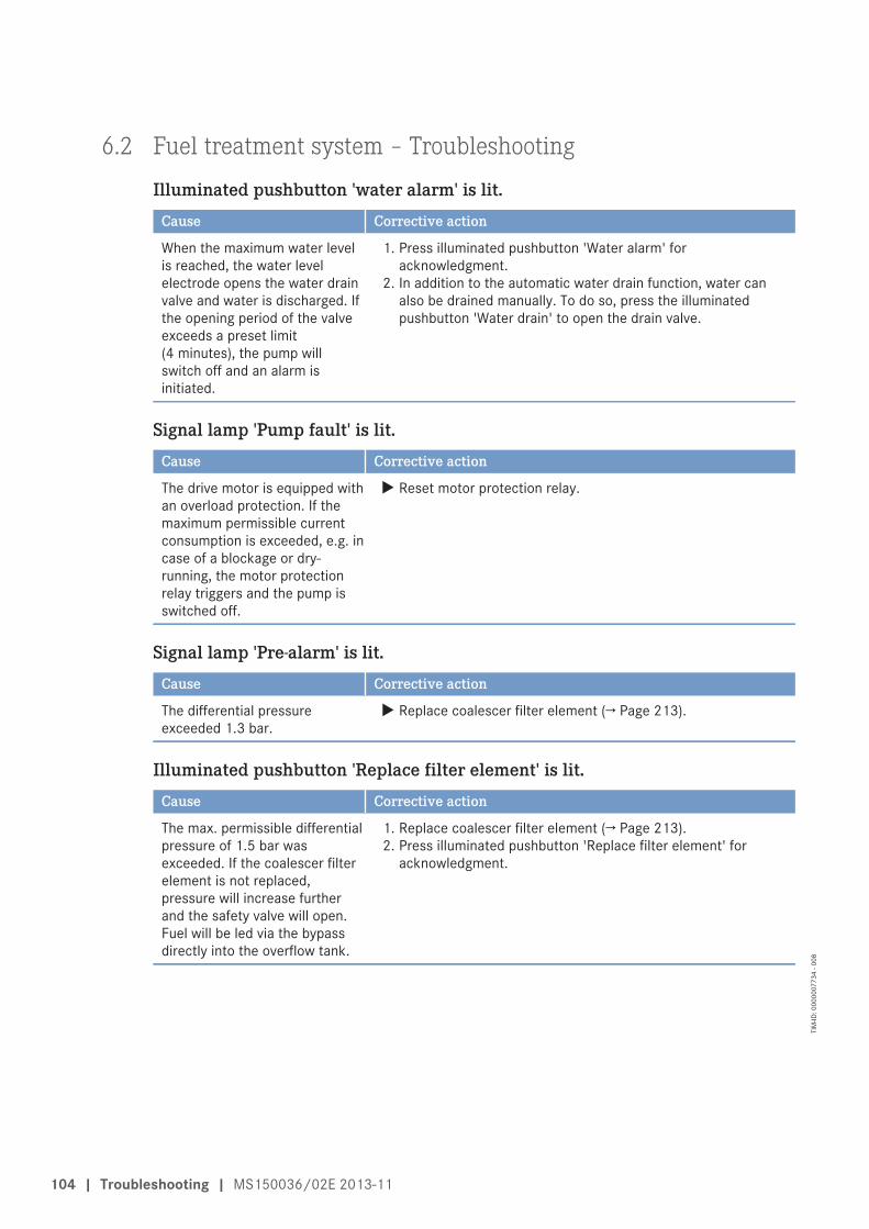
6.2 Fuel treatment system – Troubleshooting
Illuminated pushbutton 'water alarm' is lit.
Cause Corrective action
When the maximum water levelis reached, the water levelelectrode opens the water drainvalve and water is discharged. Ifthe opening period of the valveexceeds a preset limit(4 minutes), the pump willswitch off and an alarm isinitiated.
1. Press illuminated pushbutton 'Water alarm' foracknowledgment.
2. In addition to the automatic water drain function, water canalso be drained manually. To do so, press the illuminatedpushbutton 'Water drain' to open the drain valve.
Signal lamp 'Pump fault' is lit.
Cause Corrective action
The drive motor is equipped withan overload protection. If themaximum permissible currentconsumption is exceeded, e.g. incase of a blockage or dry-running, the motor protectionrelay triggers and the pump isswitched off.
u Reset motor protection relay.
Signal lamp 'Pre-alarm' is lit.
Cause Corrective action
The differential pressureexceeded 1.3 bar.
u Replace coalescer filter element (→ Page 213).
Illuminated pushbutton 'Replace filter element' is lit.
Cause Corrective action
The max. permissible differentialpressure of 1.5 bar wasexceeded. If the coalescer filterelement is not replaced,pressure will increase furtherand the safety valve will open.Fuel will be led via the bypassdirectly into the overflow tank.
1. Replace coalescer filter element (→ Page 213).2. Press illuminated pushbutton 'Replace filter element' for
acknowledgment.
104 | Troubleshooting | MS150036/02E 2013-11
TIM
-ID: 0
0000
0773
4 - 0
08

6.3 Engine governor ADEC (ECU 7) fault messages for Series 4000engines, marine applicationThe fault code numbers are generated by the engine governor and transmitted to the display below (iffitted).
The fault code (1) comprises 3 digits.
Fault messages may also be caused by faulty sensors/actuators. Contact Service to have sensors/actuators tested and replaced as necessary if troubleshooting as described in the table (→ Page 106)proves unsuccessful.
For explanations of alarm configuration parameters, refer to PR 2.8008.100.
Fault code list (→ Page 106).
MS150036/02E 2013-11 | Troubleshooting | 105
TIM
-ID: 0
0000
1686
7 - 0
06

6.4 ADEC engine governor – Fault codes
29 – HI ETC Idle Speed too HighZKP-Number: 18.004.206
Cause Corrective action
Idle speed of one of thesecondary turbochargers is toohigh.
u Contact Service.
38 – AL ETC Speed DeviationZKP-Number: 18.004.205
Cause Corrective action
Speeds of one of the secondaryturbochargers deviates fromprimary turbocharger speed.
1. Reduce power.2. Contact Service.
39 – AL ETC2 CutIn FailureZKP-Number: 18.004.204
Cause Corrective action
ETC2 could not be cut in. 1. Reduce power.2. Contact Service.
81 – AL Rail LeakageZKP-Number: 18.004.046
Cause Corrective action
Pressure gradient in rail is toolow during starting or too highduring stopping (HP systemleaky or air in the system)
u Contact Service.
102 – AL Cons. Counter DefectZKP-Number: 18.004.624
Cause Corrective action
Consumption meter faulty. u Contact Service.
104 – AL Eng Hours Counter DefectZKP-Number: 18.004.623
Cause Corrective action
Hourmeter faulty. u Contact Service.
106 | Troubleshooting | MS150036/02E 2013-11
TIM
-ID: 0
0000
1838
9 - 0
03

141 – AL Power too highZKP-Number: 11.088.007
Cause Corrective action
This alarm occurs if the averagevalue of power over the last 24hours exceeded the maximumvalue specified inPR1.1088.001.
u Reduce power.
142 – AL MCR exceeded 1 hourZKP-Number: 11.088.006
Cause Corrective action
This alarm occurs if the MCRwas exceeded for more than 1hour within the last 12 hours.
u Reduce power.
201 – SD T-CoolantZKP-Number: 18.004.570
Cause Corrective action
Coolant temperature sensorfaulty; Short circuit or wirebreak
1. Check sensor and cabling (B6), replace as necessary.2. Error cleared after restarting the engine.
202 – SD T-FuelZKP-Number: 18.004.572
Cause Corrective action
Coolant temperature sensorfaulty; Short circuit or wirebreak
1. Check sensor and cabling (B33), replace as necessary.2. Error cleared after restarting the engine.
203 – SD T-Charge AirZKP-Number: 18.004.571
Cause Corrective action
Charge-air temperature sensorfaulty; Short circuit or wirebreak
1. Check sensor and cabling (B9), replace as necessary.2. Error cleared after restarting the engine.
204 – SD Level Lube OilZKP-Number: 18.004.602
Cause Corrective action
lube oil level sensor faulty; Shortcircuit or wire break
u Check sensor and cabling, replace as necessary.
MS150036/02E 2013-11 | Troubleshooting | 107
TIM
-ID: 0
0000
1838
9 - 0
03

205 – SD T-Coolant IntercoolerZKP-Number: 18.004.574
Cause Corrective action
Intercooler coolant temperaturesensor faulty; Short circuit orwire break
u Check sensor and cabling (B26), replace as necessary.
206 – SD T-Exhaust AZKP-Number: 18.004.576
Cause Corrective action
Exhaust temperature sensor onA-side faulty; Short circuit orwire break
u Check sensor and cabling (B4.21), replace as necessary.
207 – SD T-Exhaust BZKP-Number: 18.004.577
Cause Corrective action
Exhaust temperature sensor onB-side faulty; Short circuit orwire break
u Check sensor and cabling (B4.22), replace as necessary.
208 – SD P-Charge AirZKP-Number: 18.004.566
Cause Corrective action
Charge-air pressure sensorfaulty; Short circuit or wirebreak
1. Check sensor and cabling (B10), replace as necessary.2. Error cleared after restarting the engine.
211 – SD P-Lube OilZKP-Number: 18.004.563
Cause Corrective action
Lube oil pressure sensor faulty;Short circuit or wire break
1. Check sensor and cabling (B5), replace as necessary.2. Error cleared after restarting the engine.
212 – SD P-CoolantZKP-Number: 18.004.564
Cause Corrective action
Coolant pressure sensor faulty;Short circuit or wire break
1. Check sensor and cabling (B16), replace as necessary.2. Error cleared after restarting the engine.
108 | Troubleshooting | MS150036/02E 2013-11
TIM
-ID: 0
0000
1838
9 - 0
03

213 – SD P-Coolant IntercoolerZKP-Number: 18.004.569
Cause Corrective action
Intercooler coolant pressuresensor faulty; Short circuit orwire break
1. Check sensor and cabling (B43), replace as necessary.2. Error cleared after restarting the engine.
214 – SD P-CrankCaseZKP-Number: 18.004.568
Cause Corrective action
Crankcase pressure sensorfaulty; Short circuit or wirebreak
1. Check sensor and cabling (B50), replace as necessary.2. Error cleared after restarting the engine.
215 – SD P-HDZKP-Number: 18.004.567
Cause Corrective action
Rail pressure sensor faulty; high-pressure regulator emergencymode; Short circuit or wirebreak
1. Check sensor and cabling (B48), replace as necessary.2. Error cleared after restarting the engine.
216 – SD T-Lube OilZKP-Number: 18.004.575
Cause Corrective action
Lube oil temperature sensorfaulty; Short circuit or wirebreak
1. Check sensor and cabling (B7), replace as necessary.2. Error cleared after restarting the engine.
219 – SD T-Intake AirZKP-Number: 18.004.573
Cause Corrective action
Intake air temperature sensorfaulty; Short circuit or wirebreak
1. Check sensor and cabling (B3), replace as necessary.2. Error cleared after restarting the engine.
220 – SD Level Coolant WaterZKP-Number: 18.004.584
Cause Corrective action
Coolant level sensor faulty;Short circuit or wire break
1. Check sensor and cabling (F33), replace as necessary.2. Error cleared after restarting the engine.
MS150036/02E 2013-11 | Troubleshooting | 109
TIM
-ID: 0
0000
1838
9 - 0
03

221 – SD P-Diff-Lube OilZKP-Number: 18.004.585
Cause Corrective action
Lube oil differential pressuresensor faulty; Short circuit orwire break
1. Check sensor and cabling (F25), replace as necessary.2. Error cleared after restarting the engine.
222 – SD Level Leakage FuelZKP-Number: 18.004.582
Cause Corrective action
Leak-off fuel level sensor faulty;Short circuit or wire break
1. Check sensor and cabling (F46), replace as necessary.2. Error cleared after restarting the engine.
223 – SD Level Coolant IntercoolerZKP-Number: 18.004.583
Cause Corrective action
Coolant level sensor ofintercooler faulty; Short circuitor wire break
1. Check sensor and cabling (F57), replace as necessary.2. Error cleared after restarting the engine.
227 – SD P-Lube Oil before FilterZKP-Number: 18.004.620
Cause Corrective action
Sensor for lube oil pressurebefore filter faulty; Short circuitor wire break
1. Check sensor and cabling (B5.3), replace as necessary.2. Error cleared after restarting the engine.
228 – SD P-Fuel before FilterZKP-Number: 18.004.595
Cause Corrective action
Fuel pressure sensor faulty;Short circuit or wire break
1. Check sensor and cabling (B5.3), replace as necessary.2. Error cleared after restarting the engine.
229 – AL Stop Camshaft Sensor DefectZKP-Number: 18.004.562
Cause Corrective action
Engine shutdown due tocamshaft sensor fault (and aprior crankshaft sensor fault inthe same operating cycle).
1. Check connector and cabling to sensor B1, replace asnecessary.
2. Error cleared after restarting the engine.
110 | Troubleshooting | MS150036/02E 2013-11
TIM
-ID: 0
0000
1838
9 - 0
03

230 – SD Crankshaft SpeedZKP-Number: 18.004.498
Cause Corrective action
Crankshaft sensor faulty; Shortcircuit or wire break
1. Check sensor and cabling (B13), replace as necessary.2. Error cleared after restarting the engine.
231 – SD Camshaft SpeedZKP-Number: 18.004.499
Cause Corrective action
Camshaft sensor faulty; Shortcircuit or wire break
1. Check sensor and cabling (B1), replace as necessary.2. Error cleared after restarting the engine.
232 – SD Charger 1 SpeedZKP-Number: 13.011.128
Cause Corrective action
Speed sensor of primaryturbocharger faulty; Short circuitor wire break
1. Check sensor and cabling (B44.1), replace as necessary.2. Error cleared after restarting the engine.
233 – SD Charger 2 SpeedZKP-Number: 13.011.129
Cause Corrective action
Speed sensor of secondaryturbocharger faulty; Short circuitor wire break
1. Check sensor and cabling (B44.2), replace as necessary.2. Error cleared after restarting the engine.
239 – SD P-Diff FuelZKP-Number: 18.004.598
Cause Corrective action
Fuel differential pressure sensorfaulty; occurs only incombination with alarm "SD P-Fuel before Filter" or "SD P-Fuelafter Filter".
u Note further fault messages. Pressure sensor before or afterfilter is faulty.
240 – SD P-FuelZKP-Number: 18.004.565
Cause Corrective action
Fuel pressure sensor faulty;Short circuit or wire break
1. Check sensor and cabling (B34), replace as necessary.2. Error cleared after restarting the engine.
MS150036/02E 2013-11 | Troubleshooting | 111
TIM
-ID: 0
0000
1838
9 - 0
03

241 – SD T-UmblasenZKP-Number: 18.004.581
Cause Corrective action
Recirculation temperaturesensor faulty; Short circuit orwire break
1. Check sensor and cabling (B49), replace as necessary.2. Error cleared after restarting the engine.
242 – SD T-Coolant (R)ZKP-Number: 18.004.622
Cause Corrective action
Redundant coolant temperaturesensor faulty; Short circuit orwire break
1. Check sensor and cabling, replace as necessary.2. Error cleared after restarting the engine.
244 – SD P-Lube Oil (R)ZKP-Number: 18.004.621
Cause Corrective action
Redundant lube oil pressuresensor faulty; Short circuit orwire break
1. Check sensor and cabling, replace as necessary.2. Error cleared after restarting the engine.
301 – AL Timing Cylinder A1ZKP-Number: 18.004.500
Cause Corrective action
Time-of-flight measuring fault ofinjector in cylinder A1: Time-offlight measured value extremelylow or extremely high.
u If alarm occurs frequently, replace solenoid valve of injector
302 – AL Timing Cylinder A2ZKP-Number: 18.004.501
Cause Corrective action
Time-of-flight measuring fault ofinjector in cylinder A2: Time-offlight measured value extremelylow or extremely high.
u If alarm occurs frequently, replace solenoid valve of injector
112 | Troubleshooting | MS150036/02E 2013-11
TIM
-ID: 0
0000
1838
9 - 0
03
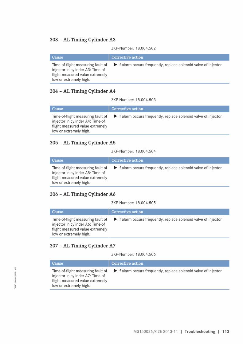
303 – AL Timing Cylinder A3ZKP-Number: 18.004.502
Cause Corrective action
Time-of-flight measuring fault ofinjector in cylinder A3: Time-offlight measured value extremelylow or extremely high.
u If alarm occurs frequently, replace solenoid valve of injector
304 – AL Timing Cylinder A4ZKP-Number: 18.004.503
Cause Corrective action
Time-of-flight measuring fault ofinjector in cylinder A4: Time-offlight measured value extremelylow or extremely high.
u If alarm occurs frequently, replace solenoid valve of injector
305 – AL Timing Cylinder A5ZKP-Number: 18.004.504
Cause Corrective action
Time-of-flight measuring fault ofinjector in cylinder A5: Time-offlight measured value extremelylow or extremely high.
u If alarm occurs frequently, replace solenoid valve of injector
306 – AL Timing Cylinder A6ZKP-Number: 18.004.505
Cause Corrective action
Time-of-flight measuring fault ofinjector in cylinder A6: Time-offlight measured value extremelylow or extremely high.
u If alarm occurs frequently, replace solenoid valve of injector
307 – AL Timing Cylinder A7ZKP-Number: 18.004.506
Cause Corrective action
Time-of-flight measuring fault ofinjector in cylinder A7: Time-offlight measured value extremelylow or extremely high.
u If alarm occurs frequently, replace solenoid valve of injector
MS150036/02E 2013-11 | Troubleshooting | 113
TIM
-ID: 0
0000
1838
9 - 0
03

308 – AL Timing Cylinder A8ZKP-Number: 18.004.507
Cause Corrective action
Time-of-flight measuring fault ofinjector in cylinder A8: Time-offlight measured value extremelylow or extremely high.
u If alarm occurs frequently, replace solenoid valve of injector
309 – AL Timing Cylinder A9ZKP-Number: 18.004.508
Cause Corrective action
Time-of-flight measuring fault ofinjector in cylinder A9: Time-offlight measured value extremelylow or extremely high.
u If alarm occurs frequently, replace solenoid valve of injector
310 – AL Timing Cylinder A10ZKP-Number: 18.004.509
Cause Corrective action
Time-of-flight measuring fault ofinjector in cylinder A10: Time-offlight measured value extremelylow or extremely high.
u If alarm occurs frequently, replace solenoid valve of injector
311 – AL Timing Cylinder B1ZKP-Number: 18.004.510
Cause Corrective action
Time-of-flight measuring fault ofinjector B1: Time-of flightmeasured value extremely lowor extremely high.
u If alarm occurs frequently, replace solenoid valve of injector
312 – AL Timing Cylinder B2ZKP-Number: 18.004.511
Cause Corrective action
Time-of-flight measuring fault ofinjector B2: Time-of flightmeasured value extremely lowor extremely high.
u If alarm occurs frequently, replace solenoid valve of injector
114 | Troubleshooting | MS150036/02E 2013-11
TIM
-ID: 0
0000
1838
9 - 0
03

313 – AL Timing Cylinder B3ZKP-Number: 18.004.512
Cause Corrective action
Time-of-flight measuring fault ofinjector B3: Time-of flightmeasured value extremely lowor extremely high.
u If alarm occurs frequently, replace solenoid valve of injector
314 – AL Timing Cylinder B4ZKP-Number: 18.004.513
Cause Corrective action
Time-of-flight measuring fault ofinjector B4: Time-of flightmeasured value extremely lowor extremely high.
u If alarm occurs frequently, replace solenoid valve of injector
315 – AL Timing Cylinder B5ZKP-Number: 18.004.514
Cause Corrective action
Time-of-flight measuring fault ofinjector B5: Time-of flightmeasured value extremely lowor extremely high.
u If alarm occurs frequently, replace solenoid valve of injector
316 – AL Timing Cylinder B6ZKP-Number: 18.004.515
Cause Corrective action
Time-of-flight measuring fault ofinjector B6: Time-of flightmeasured value extremely lowor extremely high.
u If alarm occurs frequently, replace solenoid valve of injector
317 – AL Timing Cylinder B7ZKP-Number: 18.004.516
Cause Corrective action
Time-of-flight measuring fault ofinjector B7: Time-of flightmeasured value extremely lowor extremely high.
u If alarm occurs frequently, replace solenoid valve of injector
MS150036/02E 2013-11 | Troubleshooting | 115
TIM
-ID: 0
0000
1838
9 - 0
03

318 – AL Timing Cylinder B8ZKP-Number: 18.004.517
Cause Corrective action
Time-of-flight measuring fault ofinjector B8: Time-of flightmeasured value extremely lowor extremely high.
u If alarm occurs frequently, replace solenoid valve of injector
319 – AL Timing Cylinder B9ZKP-Number: 18.004.518
Cause Corrective action
Time-of-flight measuring fault ofinjector B9: Time-of flightmeasured value extremely lowor extremely high.
u If alarm occurs frequently, replace solenoid valve of injector
320 – AL Timing Cylinder B10ZKP-Number: 18.004.519
Cause Corrective action
Time-of-flight measuring fault ofinjector B10: Time-of flightmeasured value extremely lowor extremely high.
u If alarm occurs frequently, replace solenoid valve of injector
321 – AL Wiring Cylinder A1ZKP-Number: 18.004.520
Cause Corrective action
Short-circuit in injector cablingto cylinder A1. Result: Misfiring
1. Rectify short circuit in injector solenoid valve circuit (positive tonegative) (e.g. by injector replacement)
2. Error cleared after restarting the engine.
322 – AL Wiring Cylinder A2ZKP-Number: 18.004.521
Cause Corrective action
Short-circuit in injector cablingto cylinder A2. Result: Misfiring
1. Rectify short circuit in injector solenoid valve circuit (positive tonegative) (e.g. by injector replacement)
2. Error cleared after restarting the engine.
116 | Troubleshooting | MS150036/02E 2013-11
TIM
-ID: 0
0000
1838
9 - 0
03

323 – AL Wiring Cylinder A3ZKP-Number: 18.004.522
Cause Corrective action
Short-circuit in injector cablingto cylinder A3. Result: Misfiring
1. Rectify short circuit in injector solenoid valve circuit (positive tonegative) (e.g. by injector replacement)
2. Error cleared after restarting the engine.
324 – AL Wiring Cylinder A4ZKP-Number: 18.004.523
Cause Corrective action
Short-circuit in injector cablingto cylinder A4. Result: Misfiring
1. Rectify short circuit in injector solenoid valve circuit (positive tonegative) (e.g. by injector replacement)
2. Error cleared after restarting the engine.
325 – AL Wiring Cylinder A5ZKP-Number: 18.004.524
Cause Corrective action
Short-circuit in injector cablingto cylinder A5. Result: Misfiring
1. Rectify short circuit in injector solenoid valve circuit (positive tonegative) (e.g. by injector replacement)
2. Error cleared after restarting the engine.
326 – AL Wiring Cylinder A6ZKP-Number: 18.004.525
Cause Corrective action
Short-circuit in injector cablingto cylinder A6. Result: Misfiring
1. Rectify short circuit in injector solenoid valve circuit (positive tonegative) (e.g. by injector replacement)
2. Error cleared after restarting the engine.
327 – AL Wiring Cylinder A7ZKP-Number: 18.004.526
Cause Corrective action
Short-circuit in injector cablingto cylinder A7. Result: Misfiring
1. Rectify short circuit in injector solenoid valve circuit (positive tonegative) (e.g. by injector replacement)
2. Error cleared after restarting the engine.
328 – AL Wiring Cylinder A8ZKP-Number: 18.004.527
Cause Corrective action
Short-circuit in injector cablingto cylinder A8. Result: Misfiring
1. Rectify short circuit in injector solenoid valve circuit (positive tonegative) (e.g. by injector replacement)
2. Error cleared after restarting the engine.
MS150036/02E 2013-11 | Troubleshooting | 117
TIM
-ID: 0
0000
1838
9 - 0
03

329 – AL Wiring Cylinder A9ZKP-Number: 18.004.528
Cause Corrective action
Short-circuit in injector cablingto cylinder A9. Result: Misfiring
1. Rectify short circuit in injector solenoid valve circuit (positive tonegative) (e.g. by injector replacement)
2. Error cleared after restarting the engine.
330 – AL Wiring Cylinder A10ZKP-Number: 18.004.529
Cause Corrective action
Short-circuit in injector cablingto cylinder A10. Result: Misfiring
1. Rectify short circuit in injector solenoid valve circuit (positive tonegative) (e.g. by injector replacement)
2. Error cleared after restarting the engine.
331 – AL Wiring Cylinder B1ZKP-Number: 18.004.530
Cause Corrective action
Cabling fault in injector cablingto cylinder B1. Result: Misfiring
1. Rectify short circuit in injector solenoid valve circuit (positive tonegative) (e.g. by injector replacement)
2. Error cleared after restarting the engine.
332 – AL Wiring Cylinder B2ZKP-Number: 18.004.531
Cause Corrective action
Cabling fault in injector cablingto cylinder B2. Result: Misfiring
1. Rectify short circuit in injector solenoid valve circuit (positive tonegative) (e.g. by injector replacement)
2. Error cleared after restarting the engine.
333 – AL Wiring Cylinder B3ZKP-Number: 18.004.532
Cause Corrective action
Cabling fault in injector cablingto cylinder B3. Result: Misfiring
1. Rectify short circuit in injector solenoid valve circuit (positive tonegative) (e.g. by injector replacement)
2. Error cleared after restarting the engine.
334 – AL Wiring Cylinder B4ZKP-Number: 18.004.533
Cause Corrective action
Cabling fault in injector cablingto cylinder B4. Result: Misfiring
1. Rectify short circuit in injector solenoid valve circuit (positive tonegative) (e.g. by injector replacement)
2. Error cleared after restarting the engine.
118 | Troubleshooting | MS150036/02E 2013-11
TIM
-ID: 0
0000
1838
9 - 0
03
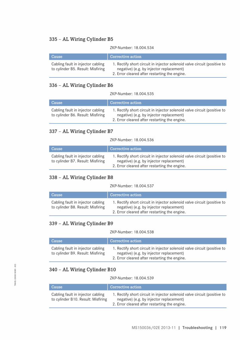
335 – AL Wiring Cylinder B5ZKP-Number: 18.004.534
Cause Corrective action
Cabling fault in injector cablingto cylinder B5. Result: Misfiring
1. Rectify short circuit in injector solenoid valve circuit (positive tonegative) (e.g. by injector replacement)
2. Error cleared after restarting the engine.
336 – AL Wiring Cylinder B6ZKP-Number: 18.004.535
Cause Corrective action
Cabling fault in injector cablingto cylinder B6. Result: Misfiring
1. Rectify short circuit in injector solenoid valve circuit (positive tonegative) (e.g. by injector replacement)
2. Error cleared after restarting the engine.
337 – AL Wiring Cylinder B7ZKP-Number: 18.004.536
Cause Corrective action
Cabling fault in injector cablingto cylinder B7. Result: Misfiring
1. Rectify short circuit in injector solenoid valve circuit (positive tonegative) (e.g. by injector replacement)
2. Error cleared after restarting the engine.
338 – AL Wiring Cylinder B8ZKP-Number: 18.004.537
Cause Corrective action
Cabling fault in injector cablingto cylinder B8. Result: Misfiring
1. Rectify short circuit in injector solenoid valve circuit (positive tonegative) (e.g. by injector replacement)
2. Error cleared after restarting the engine.
339 – AL Wiring Cylinder B9ZKP-Number: 18.004.538
Cause Corrective action
Cabling fault in injector cablingto cylinder B9. Result: Misfiring
1. Rectify short circuit in injector solenoid valve circuit (positive tonegative) (e.g. by injector replacement)
2. Error cleared after restarting the engine.
340 – AL Wiring Cylinder B10ZKP-Number: 18.004.539
Cause Corrective action
Cabling fault in injector cablingto cylinder B10. Result: Misfiring
1. Rectify short circuit in injector solenoid valve circuit (positive tonegative) (e.g. by injector replacement)
2. Error cleared after restarting the engine.
MS150036/02E 2013-11 | Troubleshooting | 119
TIM
-ID: 0
0000
1838
9 - 0
03

341 – AL Open Load Cylinder A1ZKP-Number: 18.004.540
Cause Corrective action
Disruption fault in injectorcabling to cylinder A1. Result:Misfiring
1. Check continuity of injector cabling or exclude open load insolenoid valve circuit (e.g. by injector replacement)
2. Error clearance: After each working cycle.
342 – AL Open Load Cylinder A2ZKP-Number: 18.004.541
Cause Corrective action
Disruption fault in injectorcabling to cylinder A2. Result:Misfiring
1. Check continuity of injector cabling or exclude open load insolenoid valve circuit (e.g. by injector replacement)
2. Error clearance: After each working cycle.
343 – AL Open Load Cylinder A3ZKP-Number: 18.004.542
Cause Corrective action
Disruption fault in injectorcabling to cylinder A3. Result:Misfiring
1. Check continuity of injector cabling or exclude open load insolenoid valve circuit (e.g. by injector replacement)
2. Error clearance: After each working cycle.
344 – AL Open Load Cylinder A4ZKP-Number: 18.004.543
Cause Corrective action
Disruption fault in injectorcabling to cylinder A4. Result:Misfiring
1. Check continuity of injector cabling or exclude open load insolenoid valve circuit (e.g. by injector replacement)
2. Error clearance: After each working cycle.
345 – AL Open Load Cylinder A5ZKP-Number: 18.004.544
Cause Corrective action
Disruption fault in injectorcabling to cylinder A5. Result:Misfiring
1. Check continuity of injector cabling or exclude open load insolenoid valve circuit (e.g. by injector replacement)
2. Error clearance: After each working cycle.
346 – AL Open Load Cylinder A6ZKP-Number: 18.004.545
Cause Corrective action
Disruption fault in injectorcabling to cylinder A6. Result:Misfiring
1. Check continuity of injector cabling or exclude open load insolenoid valve circuit (e.g. by injector replacement)
2. Error clearance: After each working cycle.
120 | Troubleshooting | MS150036/02E 2013-11
TIM
-ID: 0
0000
1838
9 - 0
03

347 – AL Open Load Cylinder A7ZKP-Number: 18.004.546
Cause Corrective action
Disruption fault in injectorcabling to cylinder A7. Result:Misfiring
1. Check continuity of injector cabling or exclude open load insolenoid valve circuit (e.g. by injector replacement)
2. Error clearance: After each working cycle.
348 – AL Open Load Cylinder A8ZKP-Number: 18.004.547
Cause Corrective action
Disruption fault in injectorcabling to cylinder A8. Result:Misfiring
1. Check continuity of injector cabling or exclude open load insolenoid valve circuit (e.g. by injector replacement)
2. Error clearance: After each working cycle.
349 – AL Open Load Cylinder A9ZKP-Number: 18.004.548
Cause Corrective action
Disruption fault in injectorcabling to cylinder A9. Result:Misfiring
1. Check continuity of injector cabling or exclude open load insolenoid valve circuit (e.g. by injector replacement)
2. Error clearance: After each working cycle.
350 – AL Open Load Cylinder A10ZKP-Number: 18.004.549
Cause Corrective action
Disruption fault in injectorcabling to cylinder A10. Result:Misfiring
1. Check continuity of injector cabling or exclude open load insolenoid valve circuit (e.g. by injector replacement)
2. Error clearance: After each working cycle.
351 – AL Open Load Cylinder B1ZKP-Number: 18.004.550
Cause Corrective action
Disruption fault in injectorcabling to cylinder B1. Result:Misfiring
1. Check continuity of injector cabling or exclude open load insolenoid valve circuit (e.g. by injector replacement)
2. Error clearance: After each working cycle.
352 – AL Open Load Cylinder B2ZKP-Number: 18.004.551
Cause Corrective action
Disruption fault in injectorcabling to cylinder B2. Result:Misfiring
1. Check continuity of injector cabling or exclude open load insolenoid valve circuit (e.g. by injector replacement)
2. Error clearance: After each working cycle.
MS150036/02E 2013-11 | Troubleshooting | 121
TIM
-ID: 0
0000
1838
9 - 0
03
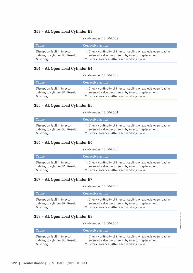
353 – AL Open Load Cylinder B3ZKP-Number: 18.004.552
Cause Corrective action
Disruption fault in injectorcabling to cylinder B3. Result:Misfiring
1. Check continuity of injector cabling or exclude open load insolenoid valve circuit (e.g. by injector replacement)
2. Error clearance: After each working cycle.
354 – AL Open Load Cylinder B4ZKP-Number: 18.004.553
Cause Corrective action
Disruption fault in injectorcabling to cylinder B4. Result:Misfiring
1. Check continuity of injector cabling or exclude open load insolenoid valve circuit (e.g. by injector replacement)
2. Error clearance: After each working cycle.
355 – AL Open Load Cylinder B5ZKP-Number: 18.004.554
Cause Corrective action
Disruption fault in injectorcabling to cylinder B5. Result:Misfiring
1. Check continuity of injector cabling or exclude open load insolenoid valve circuit (e.g. by injector replacement)
2. Error clearance: After each working cycle.
356 – AL Open Load Cylinder B6ZKP-Number: 18.004.555
Cause Corrective action
Disruption fault in injectorcabling to cylinder B6. Result:Misfiring
1. Check continuity of injector cabling or exclude open load insolenoid valve circuit (e.g. by injector replacement)
2. Error clearance: After each working cycle.
357 – AL Open Load Cylinder B7ZKP-Number: 18.004.556
Cause Corrective action
Disruption fault in injectorcabling to cylinder B7. Result:Misfiring
1. Check continuity of injector cabling or exclude open load insolenoid valve circuit (e.g. by injector replacement)
2. Error clearance: After each working cycle.
358 – AL Open Load Cylinder B8ZKP-Number: 18.004.557
Cause Corrective action
Disruption fault in injectorcabling to cylinder B8. Result:Misfiring
1. Check continuity of injector cabling or exclude open load insolenoid valve circuit (e.g. by injector replacement)
2. Error clearance: After each working cycle.
122 | Troubleshooting | MS150036/02E 2013-11
TIM
-ID: 0
0000
1838
9 - 0
03

359 – AL Open Load Cylinder B9ZKP-Number: 18.004.558
Cause Corrective action
Disruption fault in injectorcabling to cylinder B9. Result:Misfiring
1. Check continuity of injector cabling or exclude open load insolenoid valve circuit (e.g. by injector replacement)
2. Error clearance: After each working cycle.
360 – AL Open Load Cylinder B10ZKP-Number: 18.004.559
Cause Corrective action
Disruption fault in injectorcabling to cylinder B10. Result:Misfiring
1. Check continuity of injector cabling or exclude open load insolenoid valve circuit (e.g. by injector replacement)
2. Error clearance: After each working cycle.
361 – AL Power Stage LowZKP-Number: 18.004.496
Cause Corrective action
Internal electronic fault(electronics possibly faulty). Ifbit "1.1020.021" (Power StageFailure: Stop Engine) is set,engine will be shut down asadditional measure.
u Start ITS. If the ITS diagnosis result is "electronics OK", notefurther fault messages (e.g. cabling faults).
362 – AL Power Stage HighZKP-Number: 18.004.497
Cause Corrective action
Internal electronic fault(electronics possibly faulty). Ifbit "1.1020.021" (Power StageFailure: Stop Engine) is set,engine will be shut down asadditional measure.
u Start ITS. If the ITS diagnosis result is "electronics OK", notefurther fault messages (e.g. cabling faults).
363 – AL Stop Power StageZKP-Number: 18.004.560
Cause Corrective action
Internal electronic fault(electronics possibly faulty). Ifbit "1.1020.021" (Power StageFailure: Stop Engine) is set,engine will be shut down asadditional measure.
u Start ITS. If the ITS diagnosis result is "electronics OK", notefurther fault messages (e.g. cabling faults).
MS150036/02E 2013-11 | Troubleshooting | 123
TIM
-ID: 0
0000
1838
9 - 0
03

365 – AL Stop MV-Wiring GroundZKP-Number: 18.004.561
Cause Corrective action
Injector cabling fault. If bit"1.1020.021" (Power StageFailure: Stop Engine) is set,engine will be shut down asadditional measure. Possiblecauses:
1. Short circuit of positiveconnection of one or moreinjectors to ground
2. Short circuit of negativeconnection of one or moreinjectors to ground
u Check wiring, replace wiring harness as necessary.
371 – AL Wiring TO 1ZKP-Number: 18.004.634
Cause Corrective action
Short circuit or wire break ontransistor output 1 (TO 1).
1. Check charger valve/cabling, repair as necessary.2. Replace engine governor
372 – AL Wiring TO 2ZKP-Number: 18.004.635
Cause Corrective action
Short circuit or wire break ontransistor output 2 (TO 2).
1. Check air recirculation valve/cabling, repair as necessary2. Replace engine governor
373 – AL Wiring TO 3ZKP-Number: 18.004.636
Cause Corrective action
Short circuit or wire break ontransistor output 3 (TO 3).
u Check wiring of charger valve 2 (marine engine)
374 – AL Wiring TO 4ZKP-Number: 18.004.637
Cause Corrective action
Short circuit or wire break ontransistor output 4 (TO 4).
u Check wiring of charger valve 3 (marine engine)
124 | Troubleshooting | MS150036/02E 2013-11
TIM
-ID: 0
0000
1838
9 - 0
03
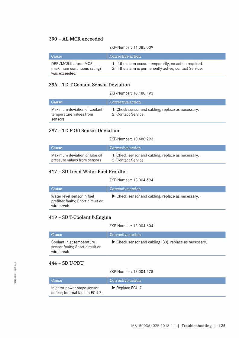
390 – AL MCR exceededZKP-Number: 11.085.009
Cause Corrective action
DBR/MCR feature: MCR(maximum continuous rating)was exceeded.
1. If the alarm occurs temporarily, no action required.2. If the alarm is permanently active, contact Service.
396 – TD T-Coolant Sensor DeviationZKP-Number: 10.480.193
Cause Corrective action
Maximum deviation of coolanttemperature values fromsensors
1. Check sensor and cabling, replace as necessary.2. Contact Service.
397 – TD P-Oil Sensor DeviationZKP-Number: 10.480.293
Cause Corrective action
Maximum deviation of lube oilpressure values from sensors
1. Check sensor and cabling, replace as necessary.2. Contact Service.
417 – SD Level Water Fuel PrefilterZKP-Number: 18.004.594
Cause Corrective action
Water level sensor in fuelprefilter faulty; Short circuit orwire break
u Check sensor and cabling, replace as necessary.
419 – SD T-Coolant b.EngineZKP-Number: 18.004.604
Cause Corrective action
Coolant inlet temperaturesensor faulty; Short circuit orwire break
u Check sensor and cabling (B3), replace as necessary.
444 – SD U-PDUZKP-Number: 18.004.578
Cause Corrective action
Injector power stage sensordefect; Internal fault in ECU 7.
u Replace ECU 7.
MS150036/02E 2013-11 | Troubleshooting | 125
TIM
-ID: 0
0000
1838
9 - 0
03
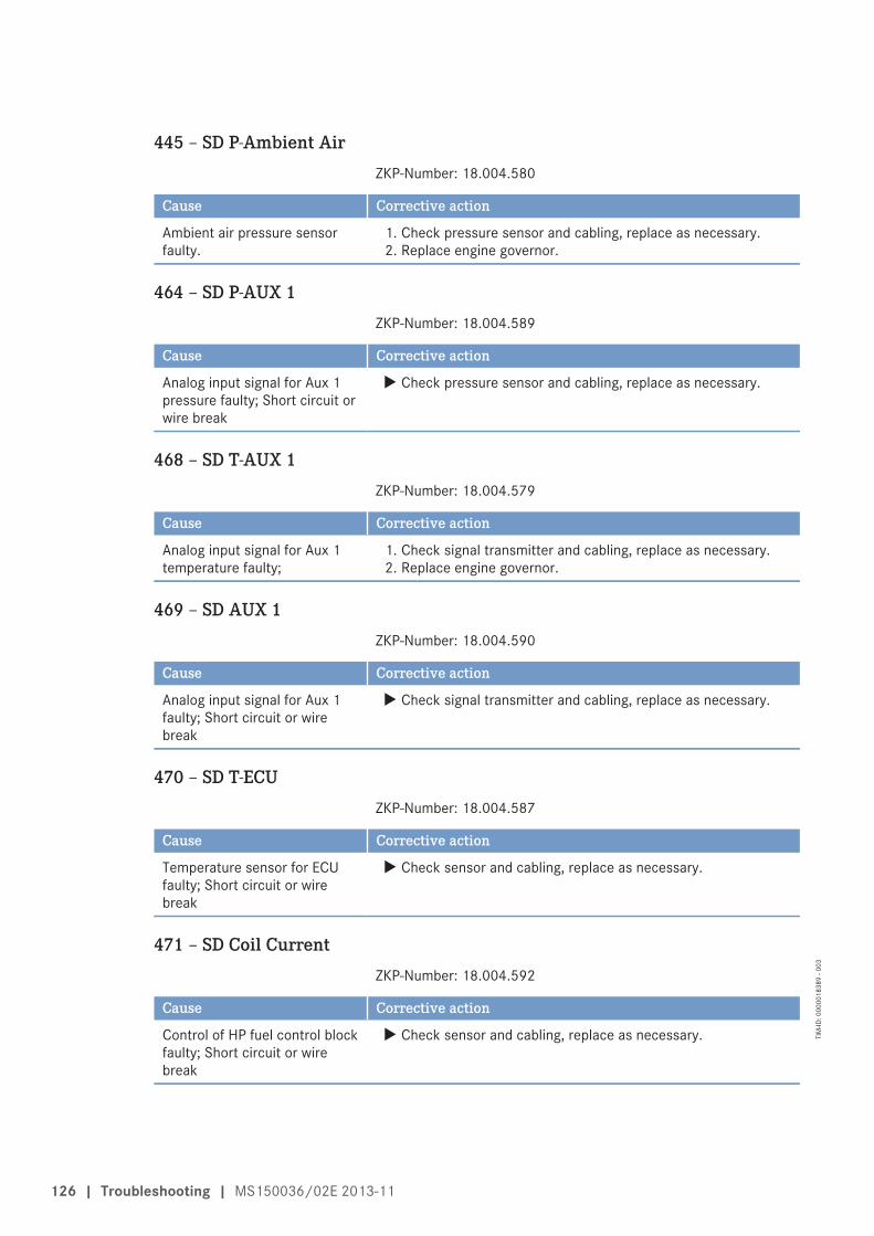
445 – SD P-Ambient AirZKP-Number: 18.004.580
Cause Corrective action
Ambient air pressure sensorfaulty.
1. Check pressure sensor and cabling, replace as necessary.2. Replace engine governor.
464 – SD P-AUX 1ZKP-Number: 18.004.589
Cause Corrective action
Analog input signal for Aux 1pressure faulty; Short circuit orwire break
u Check pressure sensor and cabling, replace as necessary.
468 – SD T-AUX 1ZKP-Number: 18.004.579
Cause Corrective action
Analog input signal for Aux 1temperature faulty;
1. Check signal transmitter and cabling, replace as necessary.2. Replace engine governor.
469 – SD AUX 1ZKP-Number: 18.004.590
Cause Corrective action
Analog input signal for Aux 1faulty; Short circuit or wirebreak
u Check signal transmitter and cabling, replace as necessary.
470 – SD T-ECUZKP-Number: 18.004.587
Cause Corrective action
Temperature sensor for ECUfaulty; Short circuit or wirebreak
u Check sensor and cabling, replace as necessary.
471 – SD Coil CurrentZKP-Number: 18.004.592
Cause Corrective action
Control of HP fuel control blockfaulty; Short circuit or wirebreak
u Check sensor and cabling, replace as necessary.
126 | Troubleshooting | MS150036/02E 2013-11
TIM
-ID: 0
0000
1838
9 - 0
03

473 – AL Wiring PWM_CM2ZKP-Number: 18.004.593
Cause Corrective action
Cable break or short circuit onchannel PWM_CM2.
1. Check cabling.2. Contact Service.
475 – AL CR Trigger Engine StopZKP-Number: 18.010.009
Cause Corrective action
Activated if the crash recorderwas triggered due to an enginestop.
1. Determine cause of trigger/engine stop and rectify.2. Contact Service.
476 – AL Crash Rec. Init. ErrorZKP-Number: 18.010.007
Cause Corrective action
Crash recorder initializationerror.
1. Check setting with DiaSys.2. Contact Service.
482 – SD T-Exhaust CZKP-Number: 18.004.596
Cause Corrective action
Exhaust temperature sensor onA-side faulty; Short circuit orwire break
u Check sensor and cabling (B4.23), replace as necessary.
483 – SD T-Exhaust DZKP-Number: 18.004.597
Cause Corrective action
Exhaust temperature sensor onA-side faulty; Short circuit orwire break
u Check sensor and cabling (B4.24), replace as necessary.
492 – AL ETC4 CutIn FailureZKP-Number: 18.004.202
Cause Corrective action
ETC4 could not be cut in. u Check control valve on ETC 4.
MS150036/02E 2013-11 | Troubleshooting | 127
TIM
-ID: 0
0000
1838
9 - 0
03

493 – AL ETC3 CutIn FailureZKP-Number: 18.004.203
Cause Corrective action
ETC3 could not be cut in. u Check control valve on ETC 3.
500 – AL Wiring POM Starter 1ZKP-Number: 14.500.900
Cause Corrective action
A wiring fault was detected inthe connection between starter1 and POM. This may be amissing consumer, a wire break,or a short circuit.
u Check connection between POM and starter.
501 – AL Wiring POM Starter 2ZKP-Number: 14.500.901
Cause Corrective action
A wiring fault was detected inthe connection between starter2 and POM. This may be amissing consumer, a wire break,or a short circuit.
u Check connection between POM and starter.
502 – AL Open Load POM AlternatorZKP-Number: 14.500.902
Cause Corrective action
Open load was detected at theconnection of the battery-charging generator on the POM.
u Check connection between POM and starter.
503 – AL Battery Not ChargingZKP-Number: 14.500.903
Cause Corrective action
The battery-charging generatordoes not charge the battery.
u Check battery-charging generator and cabling.
504 – AL CAN POM Node LostZKP-Number: 14.500.904
Cause Corrective action
POM missing on CAN bus. u Check connection and POM. If alarm occurs in combinationwith alarm 508, the resistor in the POM cabling is missing.
128 | Troubleshooting | MS150036/02E 2013-11
TIM
-ID: 0
0000
1838
9 - 0
03

506 – AL Low Starter VoltageZKP-Number: 14.500.906
Cause Corrective action
battery voltage is too low toaccomplish a startingprocedure.
u Check battery-charging generator and cabling.
507 – AL POM ErrorZKP-Number: 14.500.907
Cause Corrective action
A general POM error occurred. u Replace POM.
508 – AL Wrong POM-IDZKP-Number: 14.500.908
Cause Corrective action
POM transmits an unexpectedID number. If alarm occurs incombination with alarm 504, theresistor in the POM cabling ismissing.
u Check POM wiring harness.
519 – Oillevel Calibration ErrorZKP-Number: 10.158.921
Cause Corrective action
Error when writing thecalibration value into the Flashor SD memory of the levelsensor; associated PV: AL Group6 Mot Bit 11
1. Check sensor and cabling, replace as necessary.2. Contact Service.
525 – SD P-Lube Oil (R2)ZKP-Number: 18.004.638
Cause Corrective action
Redundant lube oil pressuresensor faulty; Short circuit orwire break
u Check sensor and cabling, replace as necessary.
526 – SD T-Coolant (R2)ZKP-Number: 18.004.639
Cause Corrective action
Redundant coolant temperaturesensor faulty; Short circuit orwire break
u Check sensor and cabling, replace as necessary.
MS150036/02E 2013-11 | Troubleshooting | 129
TIM
-ID: 0
0000
1838
9 - 0
03

527 – TD EngineSpd. Sensor DeviationZKP-Number: 10.480.093
Cause Corrective action
Maximum deviation of speedsensors
1. Check cabling of speed sensors. Observe additional messages.2. Contact Service.
528 – SD Engine Speed 3rd SensorZKP-Number: 12.500.102
Cause Corrective action
Redundant crankshaft sensorfaulty; Short circuit or wirebreak
u Check sensor and cabling, replace as necessary.
576 – AL ESCM OverrideZKP-Number: 11.075.083
Cause Corrective action
Violation of corrected MCR orDBR/MCR curve. Engineoverload!
u Reduce power.
577 – SD T-Lube Oil PanZKP-Number: 10.137.900
Cause Corrective action
Temperature sensor in oil pandefective; Short circuit or wirebreak
u Check sensor and cabling, replace as necessary.
582 – AL Emergency Stop FailedZKP-Number: 11.005.006
Cause Corrective action
This alarm occurs if the enginefails to come to a standstillwithin a specified (byparametrization) a period of timeafter the emergency stop signalwas output.
u The delay between the emergency stop signal and this alarmsignal is set in parameter 1.1005.4.
588 – SD P-Oil Refill PumpZKP-Number: 10.159.910
Cause Corrective action
Pressure sensor faulty; Shortcircuit or wire break
u Check sensor and cabling, replace as necessary.
130 | Troubleshooting | MS150036/02E 2013-11
TIM
-ID: 0
0000
1838
9 - 0
03

596 – AL Develop PR SetZKP-Number: 18.004.645
Cause Corrective action
The parameter set used is a testparameter set.
u The alarm remains active until a series-production parameterset was installed.
600 – SD T-Exhaust A+BZKP-Number: 18.004.646
Cause Corrective action
SD T-Exhaust A and T-Exhaust B u Check sensor and cabling, replace as necessary.
601 – SD ETC1+ETC2ZKP-Number: 13.011.227
Cause Corrective action
SD ETC1 and ETC2 u Check sensor and cabling, replace as necessary.
625 – SD P-Fuel before PrefilterZKP-Number: 18.004.600
Cause Corrective action
Analog input signal for pressurebefore prefilter faulty; Shortcircuit or wire break
1. Check pressure sensor and cabling, replace as necessary.2. Error cleared after restarting the engine.
MS150036/02E 2013-11 | Troubleshooting | 131
TIM
-ID: 0
0000
1838
9 - 0
03

7 Task Description
7.1 Engine
7.1.1 Engine – Barring manually
Preconditions☑ Engine is stopped and starting disabled.
Special tools, Material, Spare parts
Designation / Use Part No. Qty.
Barring device F6555766 1Ratchet with extension F30006212 1
DANGER Rotating and moving engine parts.Risk of crushing, danger of parts of the body being caught or pulled in!• Before cranking the engine, make sure that there are no persons in the engine's danger zone.• After finishing work on the engine, make sure that all safety devices are put back in place and all
tools removed from the engine.
Barring engine manually1. Release screws (1) and remove end cov-
er (2) from flywheel housing.
132 | Task Description | MS150036/02E 2013-11
TIM
-ID: 0
0000
0091
7 - 0
10
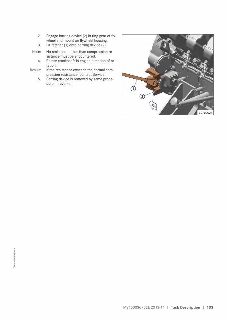
2. Engage barring device (2) in ring gear of fly-wheel and mount on flywheel housing.
3. Fit ratchet (1) onto barring device (2).
Note: No resistance other than compression re-sistance must be encountered.
4. Rotate crankshaft in engine direction of ro-tation.
Result: If the resistance exceeds the normal com-pression resistance, contact Service.
5. Barring device is removed by same proce-dure in reverse.
MS150036/02E 2013-11 | Task Description | 133
TIM
-ID: 0
0000
0091
7 - 0
10

7.1.2 Engine – Barring with starting system
Barring using the automation systemRefer to automation system operating instructions
134 | Task Description | MS150036/02E 2013-11
TIM
-ID: 0
0000
1753
2 - 0
03

7.2 Cylinder Liner
7.2.1 Cylinder liner – Endoscopic examination
Preconditions☑ Engine is stopped and starting disabled.
Special tools, Material, Spare parts
Designation / Use Part No. Qty.
Rigid endoscope Y20097353 1
Preparatory steps1. Remove cylinder head cover (→ Page 143).2. Remove injector (→ Page 147).
Positioning crankshaft at BDC1. Using barring gear, turn crankshaft until crankshaft journal of the cylinder to be inspected has reached
BDC.2. Insert endoscope into cylinder liner through injector seat.
Cylinder liner – Endoscopic examinationFindings Action• Thin carbon coating on circumference of carbon scraper ring• Slight localized additive deposits at top edge• Singular smooth areas at lower edge• Carbon deposits on circumference in clearance between top piston
ring and bottom edge of carbon scraper ring• First signs of marks left by top piston ring• Bright mark on entire circumference• Consistent honing pattern without objections• First signs of marks left by lower cooling bores• Running pattern seems darker
No action required
• Dark areas with even or varying degrees of discoloration• Beginning and end of the discoloration are not sharply defined and
do not cover the entire stroke area• Dark areas in the upper section of the cooling bore, remaining cir-
cumference without objections• Piston rings without objections
Further endoscopic examina-tion required as part of mainte-nance work
• On the entire circumference, apart from light areas of discoloration(that do not impair operation) clearly darker stripes that start at thetop piston ring
• Heat discoloration in the direction of stroke and honing patterndamage
• Heat discoloration of piston rings
Cylinder liner must be replaced;Service must be contacted
1. Compile endoscopy report using the table.2. Use technical terms for description of the liner surface (→ Page 137).3. Depending on findings:
• do not take any action or• carry out a further endoscopic examination as part of maintenance work or• contact Service; cylinder liner must be replaced.
MS150036/02E 2013-11 | Task Description | 135
TIM
-ID: 0
0000
0001
5 - 0
14

Final steps1. Install injector (→ Page 147).2. Install cylinder head cover (→ Page 143).
136 | Task Description | MS150036/02E 2013-11
TIM
-ID: 0
0000
0001
5 - 0
14

7.2.2 Instructions and comments on endoscopic and visual examination of cylinderliners
Terms used for endoscopic examinationUse the terms listed below to describe the condition of the cylinder-liner surface in the endoscopic ex-amination report.
Findings Explanations/ActionMinor dirt scores Minor dirt scores can occur during the assembly of a new engine (honing products,
particles, broken-off burrs). Removed cylinders clearly show such scoring on therunning surface under endoscope magnification. Cannot be felt with the fingernail.Findings not critical.
Single scores Clearly visible scores caused by hard particles. They usually start in the TDC areaand cross through the hone pattern in the direction of stroke.Findings not critical.
Scored area These areas consist of scores of different length and depth next to one another. Inmost cases, they are found at the 6-o'clock and 12-o'clock positions (inlet/exhaust) along the transverse engine axis.Findings not critical.
Smoothened area Smoothened areas are on the running surface but almost the whole honing patternis still visible. Smoothened areas appear brighter and more brilliant than the sur-rounding running surface.Findings not critical.
Bright area Bright areas are on the running surface and show local removal of the honing pat-tern. Grooves from honing process are not visible any more.
Discoloration This is caused by oxidation (surface discoloration through oil or fuel) and tempera-ture differences around the liner. It appears rather darker within the honed struc-ture in contrast to the bright metallic running surface. The honing pattern is undis-turbed. Discolorations extend in stroke direction and may be interrupted.Findings not critical.
Corrosion fields /spots
Corrosion fields / spots result from water (condensed water) with the valves in theoverlap (open) position. They are clearly visible due to the dark color of the honinggroove bottom.This corrosion is not critical unless there is corrosion pitting.
Black lines Black lines are a step towards heat discoloration. They are visible as a clear discol-oration from TDC to BDC in the running surface and the start of localized damageto the honing pattern.Cylinder liners with a large number of black lines around the running surface havelimited service life and should be replaced.
Burn mark This is caused by a malfunction in the liner / ring tribosystem. Usually they runover the whole ring-travel area (TDC/BDC), starting at the first TDC-ring and be-coming more visible from the second TDC-ring 2 onwards and less pronouncedfrom TDC-ring 1. The honing pattern is usually no longer visible and displays aclearly defined (straight) edge to the undisturbed surface. The damaged surface isusually discolored. The circumferential length varies.Liners with burn marks, or heat discoloration, starting in TDC-ring 1 have to be re-placed.
Seizure marks, scuff-ing
Irregular circumference lengths and depths. Can be caused either by the pistonskirt or the piston crown. Material deposits on the liner (smear), heavy discolora-tion. Severe, visible scoring.Replace liner.
MS150036/02E 2013-11 | Task Description | 137
TIM
-ID: 0
0000
0001
4 - 0
15

Evaluation of findings and further measuresThe findings in the start phase of oxidation discoloration and heat discoloration are similar. A thoroughinvestigation and compliance with the above evaluation criteria allow an unambiguous evaluation. Toavoid unnecessary disassembly work, it is recommended that another inspection be carried out afterfurther operation of the engine.
138 | Task Description | MS150036/02E 2013-11
TIM
-ID: 0
0000
0001
4 - 0
15

7.3 Valve Drive
7.3.1 Valve gear – Lubrication
Preconditions☑ Engine is stopped and starting disabled.
Special tools, Material, Spare parts
Designation / Use Part No. Qty.
Engine oil
Valve gear – Lubrication1. Remove cylinder head covers
(→ Page 143).2. Fill oil chambers of valve bridges with oil.3. Fill oil chambers of rocker arms and adjust-
ing screws with oil.4. Install cylinder head covers (→ Page 143).
MS150036/02E 2013-11 | Task Description | 139
TIM
-ID: 0
0000
0092
1 - 0
10

7.3.2 Valve clearance – Check and adjustment
Preconditions☑ Engine is stopped and starting disabled.
☑ Engine coolant temperature is max. 40 °C.
☑ Valves are closed.
Special tools, Material, Spare parts
Designation / Use Part No. Qty.
Feeler gauge Y20010128 1Torque wrench, 60-320 Nm F30047446 1Socket wrench, 24 mm F30039526 1Engine oil
Preparatory steps1. Remove cylinder head cover (→ Page 143).2. Install barring gear (→ Page 132).
3. The TDC mark (1) (if fitted) on the flywheelmust not be used for reference.
140 | Task Description | MS150036/02E 2013-11
TIM
-ID: 0
0000
1222
4 - 0
06

4. Rotate crankshaft with barring tool in en-gine direction of rotation until marking'TDC-A1' and pointer are aligned.
Diagram for 12V engines (twocrankshaft positions)
1 Cylinder A1 is in firing TDC2 Cylinder A1 is in overlap TDCI Inlet valve
X Exhaust valve
Diagram for 16V engines (twocrankshaft positions)
1 Cylinder A1 is in firing TDC2 Cylinder A1 is in overlap TDCI Inlet valve
X Exhaust valve
MS150036/02E 2013-11 | Task Description | 141
TIM
-ID: 0
0000
1222
4 - 0
06
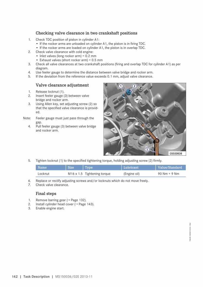
Checking valve clearance in two crankshaft positions1. Check TDC position of piston in cylinder A1:
• If the rocker arms are unloaded on cylinder A1, the piston is in firing TDC.• If the rocker arms are loaded on cylinder A1, the piston is in overlap TDC.
2. Check valve clearance with cold engine:• Inlet valves (long rocker arm) = 0.2 mm• Exhaust valves (short rocker arm) = 0.5 mm
3. Check all valve clearances at two crankshaft positions (firing and overlap TDC for cylinder A1) as perdiagram.
4. Use feeler gauge to determine the distance between valve bridge and rocker arm.5. If the deviation from the reference value exceeds 0.1 mm, adjust valve clearance.
Valve clearance adjustment1. Release locknut (1).2. Insert feeler gauge (3) between valve
bridge and rocker arm.3. Using Allen key, set adjusting screw (2) so
that the specified valve clearance is provid-ed.
Note: Feeler gauge must just pass through thegap.
4. Pull feeler gauge (3) between valve bridgeand rocker arm.
5. Tighten locknut (1) to the specified tightening torque, holding adjusting screw (2) firmly.
Name Size Type Lubricant Value/Standard
Locknut M16 x 1.5 Tightening torque (Engine oil) 90 Nm + 9 Nm
6. Replace or rectify adjusting screws and/or locknuts which do not move freely.7. Check valve clearance.
Final steps1. Remove barring gear (→ Page 132).2. Install cylinder head cover (→ Page 143).3. Enable engine start.
142 | Task Description | MS150036/02E 2013-11
TIM
-ID: 0
0000
1222
4 - 0
06

7.3.3 Cylinder head cover – Removal and installation
Preconditions☑ Engine is stopped and starting disabled.
Special tools, Material, Spare parts
Designation / Use Part No. Qty.
Gasket (→ Spare Parts Catalog)
Removing cylinder head cover1. Clean very dirty cylinder head covers prior
to removal.2. Remove screws.3. Remove cylinder head cover with gasket
from cylinder head.
Installing cylinder head cover1. Clean mating face.2. Check condition of gasket, replace if necessary.3. Place gasket and cylinder head cover on cylinder head.4. Install cylinder head cover.
MS150036/02E 2013-11 | Task Description | 143
TIM
-ID: 0
0000
0092
3 - 0
06

7.4 Injection Pump / HP Pump
7.4.1 HP pump – Filling with engine oil
Preconditions☑ Engine is stopped and starting disabled.
Special tools, Material, Spare parts
Designation / Use Part No. Qty.
Engine oil
WARNING Fuels are combustible.Risk of fire and explosion!• Avoid open flames, electrical sparks and ignition sources.• Do not smoke.
WARNING Oils/oil vapors are combustible/explosive.Risk of fire and explosion!• Avoid open flames, electric sparks and ignition sources.• Do not smoke.
NOTICE HP fuel pump not filled with engine oil.Damage to components, major material damage!• Ensure that th HP fuel pump is filled with engine oil before it is installed or put into operation.
Filling HP pump1. Remove plug screw (1).2. Use pump oiler to fill HP pump with engine
oil until engine oil emerges.3. Install plug screw (1).
144 | Task Description | MS150036/02E 2013-11
TIM
-ID: 0
0000
0164
0 - 0
12

7.4.2 HP pump – Relief bore check
DANGER Rotating and moving engine parts.Risk of crushing, danger of parts of the body being caught or pulled in!• Only run the engine at low power. Keep away from the engine's danger zone.
WARNING High level of engine noise when the engine is running.Risk of damage to hearing!• Wear ear protectors.
HP pump – Relief bore check1. Visually inspect relief bore (1) for fuel dis-
charge.2. For jacketed HP lines, leakage is indicated
by the yellow combined alarm.3. If fuel discharge is found or indicated, con-
tact Service.
MS150036/02E 2013-11 | Task Description | 145
TIM
-ID: 0
0000
1237
5 - 0
07

7.5 Injection Valve / Injector
7.5.1 Injector – Replacement
Special tools, Material, Spare parts
Designation / Use Part No. Qty.
Injector (→ Spare Parts Catalog)
Replacing injectoru Remove injector and install new injector (→ Page 147).
146 | Task Description | MS150036/02E 2013-11
TIM
-ID: 0
0000
0002
2 - 0
13
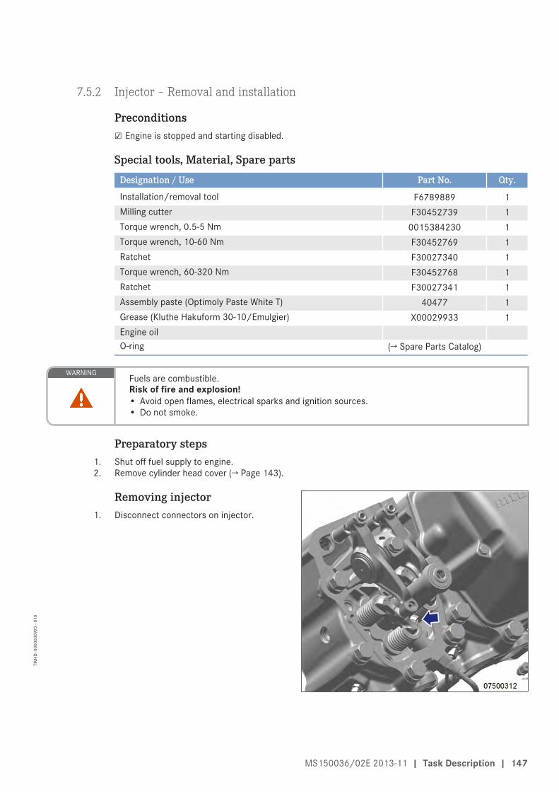
7.5.2 Injector – Removal and installation
Preconditions☑ Engine is stopped and starting disabled.
Special tools, Material, Spare parts
Designation / Use Part No. Qty.
Installation/removal tool F6789889 1Milling cutter F30452739 1Torque wrench, 0.5-5 Nm 0015384230 1Torque wrench, 10-60 Nm F30452769 1Ratchet F30027340 1Torque wrench, 60-320 Nm F30452768 1Ratchet F30027341 1Assembly paste (Optimoly Paste White T) 40477 1Grease (Kluthe Hakuform 30-10/Emulgier) X00029933 1Engine oilO-ring (→ Spare Parts Catalog)
WARNING Fuels are combustible.Risk of fire and explosion!• Avoid open flames, electrical sparks and ignition sources.• Do not smoke.
Preparatory steps1. Shut off fuel supply to engine.2. Remove cylinder head cover (→ Page 143).
Removing injector1. Disconnect connectors on injector.
MS150036/02E 2013-11 | Task Description | 147
TIM
-ID: 0
0000
0092
5 - 0
10

2. Remove HP fuel line (4).3. Remove return line (5).
Note: While the adapter is removed, the injectoris drained.
4. Remove adapter (3).5. Remove screw (2) and take off hold-down
clamp (1).
6. Install installation/removal tool on cylinderhead.
7. Remove injector with installation/removaltool.
8. Remove installation/removal tool.
9. Remove sealing ring (4) from injector oruse a self-made hook to take it out of thecylinder head.
10. Remove O-rings (3), O-ring (2) and damperring (1) from injector.
11. Clean all mating and sealing surfaces.12. Cover all connections and bores, or seal
with suitable plugs.
148 | Task Description | MS150036/02E 2013-11
TIM
-ID: 0
0000
0092
5 - 0
10

Installing injector1. Remove plug before installing the injec-
tor. (Do not remove the plug from the HPline before installing the adapter.)
2. Coat injector with assembly paste at theseat of the nozzle retaining nut.
3. Fit new sealing ring (included in the scopeof supply of the injector) with grease on in-jector, observe installation position of seal-ing ring.
4. Fit new O-rings (3) (included in the scopeof supply of the injector), O-ring (2) anddamping ring (1) onto the injector and coatwith grease.
5. Remove oil carbon from sealing face on cyl-inder head and protective sleeve with mill-ing cutter.
6. Insert injector into cylinder head, ensuringthat the HP line adapter is correctlyaligned.
7. Press in injector with installation/removaltool.
8. Remove installation/removal tool.
MS150036/02E 2013-11 | Task Description | 149
TIM
-ID: 0
0000
0092
5 - 0
10

9. Coat bolt mating face (2) and thread withengine oil.
10. Fit hold-down clamp (1) in the correct position and use torque wrench to tighten screw (2) to the speci-fied initial tightening torque.
Name Size Type Lubricant Value/Standard
Screw M12 Preload torque (Engine oil) 5 Nm to 10 Nm
Note: Ensure special cleanness.11. Coat thread and sealing cone of adapter (3) with engine oil.
12. Install adapter (3) and use torque wrench to tighten to the specified initial tightening torque.
Name Size Type Lubricant Value/Standard
Adapter Preload torque (Engine oil) 5 Nm to 10 Nm
13. Tighten screw (2) with torque wrench to the specified tightening torque.
Name Size Type Lubricant Value/Standard
Screw M12 Tightening torque 100 Nm + 10 Nm
14. Tighten adapter (3) with torque wrench to the specified tightening torque.
Name Size Type Lubricant Value/Standard
Adapter Tightening torque 100 Nm + 10 Nm
15. Install return line (7).
Note: Ensure special cleanness.16. Coat thread and sealing cone of HP line (5) with engine oil.
Note: Two HP line versions (single- and double-walled) with different torques as described below.17. Mount single-walled HP line (5) and use torque wrench to tighten to the specified torque. Tightening
sequence:1 Rail (6)2 Adapter (4)
Name Size Type Lubricant Value/Standard
Union nut / thrustscrew
Tightening torque 30 Nm + 5 Nm
150 | Task Description | MS150036/02E 2013-11
TIM
-ID: 0
0000
0092
5 - 0
10

18. Mount double-walled HP line (5) and use torque wrench to tighten to the specified torque. Tighteningsequence:
1 Adapter (4)2 Rail (6)
Name Size Type Lubricant Value/Standard
Union nut / thrustscrew
Tightening torque 40 Nm + 5 Nm
19. Fit connectors on injector.
Note: Failure to reset drift compensation (CDC)will void the emissions certification.
20. Reset drift compensation (CDC) with Dia-Sys® (→ E531920/...). If DiaSys® is notavailable, contact Service.
Final steps1. Install cylinder head cover (→ Page 143).2. Open fuel supply to engine.
MS150036/02E 2013-11 | Task Description | 151
TIM
-ID: 0
0000
0092
5 - 0
10

7.6 Fuel Filter
7.6.1 Supplementary fuel filter – Overview
1 Storage tank2 Day tank
3 Passive standard prefilterwith water separator
4 LP pump
5 Supplementary fuel filter6 Main engine filter
152 | Task Description | MS150036/02E 2013-11
TIM
-ID: 0
0000
1262
9 - 0
03

7.6.2 Additional fuel filter – Replacement
Preconditions☑ Engine is stopped and starting disabled.
Special tools, Material, Spare parts
Designation / Use Part No. Qty.
Filter wrench F30379104 1Diesel fuelEasy-change filter (→ Spare Parts Catalog)Synthetic ring (→ Spare Parts Catalog)
DANGER Rotating and moving engine parts.Risk of crushing, danger of parts of the body being caught or pulled in!• Only run the engine at low power. Keep away from the engine's danger zone.
WARNING Fuels are combustible.Risk of fire and explosion!• Avoid open flames, electrical sparks and ignition sources.• Do not smoke.
WARNING High level of engine noise when the engine is running.Risk of damage to hearing!• Wear ear protectors.
NOTICE Damage to component!Severe material damage!• For filter replacement with the engine running, operate the engine at low engine load.• The filter which is to be replaced must be cut out for a brief period only.
Additional fuel filter – Replacement1. Replace additional fuel filter with the engine stopped (→ Page 154).2. Replace additional fuel filter with the engine running (→ Page 154).
MS150036/02E 2013-11 | Task Description | 153
TIM
-ID: 0
0000
1264
5 - 0
03

7.6.3 Fuel filter – Replacement
Preconditions☑ Engine is stopped and starting disabled.
Special tools, Material, Spare parts
Designation / Use Part No. Qty.
Filter wrench F30379104 1Diesel fuelEasy-change filter (→ Spare Parts Catalog)Synthetic ring (→ Spare Parts Catalog)
DANGER Rotating and moving engine parts.Risk of crushing, danger of parts of the body being caught or pulled in!• Only run the engine at low power. Keep away from the engine's danger zone.
WARNING Fuels are combustible.Risk of fire and explosion!• Avoid open flames, electrical sparks and ignition sources.• Do not smoke.
WARNING High level of engine noise when the engine is running.Risk of damage to hearing!• Wear ear protectors.
NOTICE Damage to component!Severe material damage!• For filter replacement with the engine running, operate the engine at low engine load.• The filter which is to be replaced must be cut out for a brief period only.
Replacing fuel filter with theengine stopped
A Both filters cut inB Left filter cut outC Right filter cut out1 Fuel vent2 Fuel filter
154 | Task Description | MS150036/02E 2013-11
TIM
-ID: 0
0000
1270
4 - 0
03
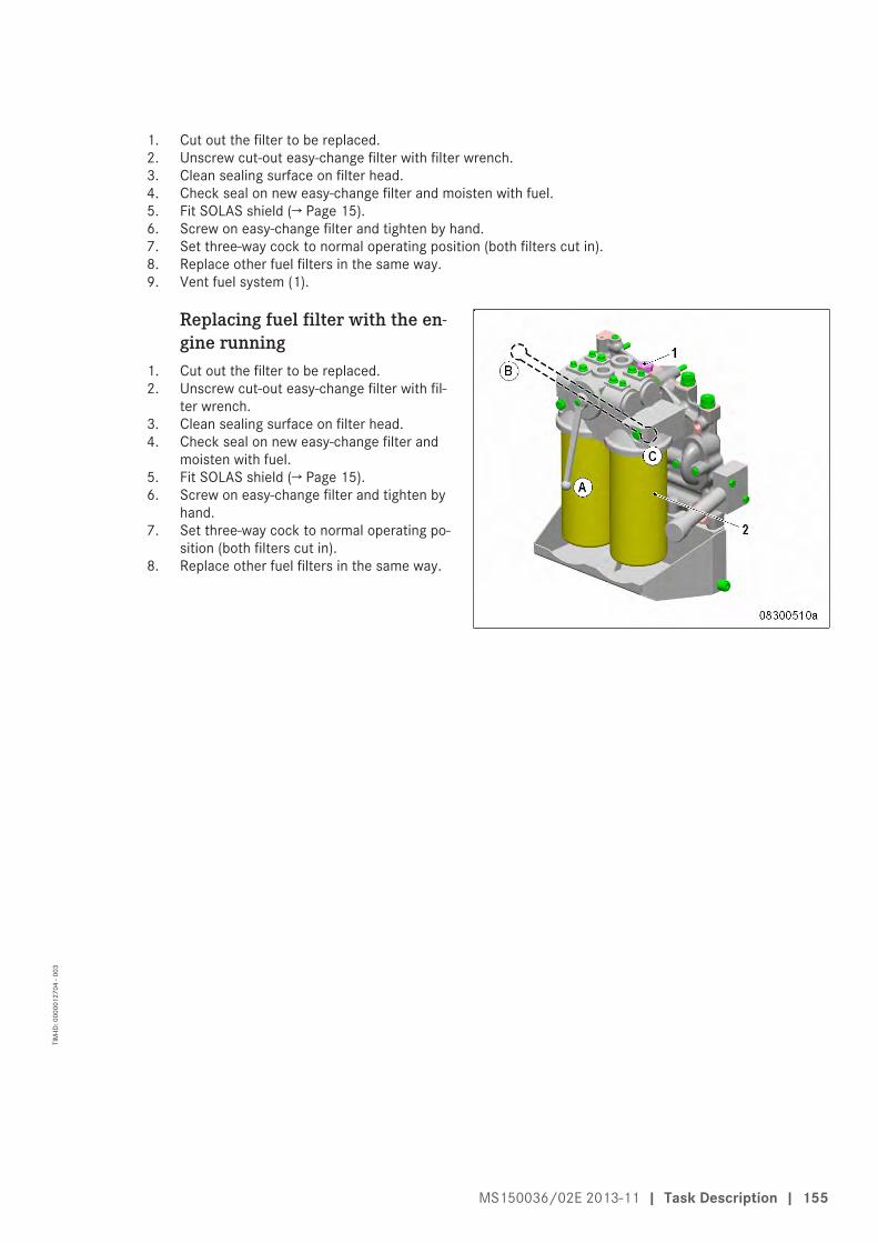
1. Cut out the filter to be replaced.2. Unscrew cut-out easy-change filter with filter wrench.3. Clean sealing surface on filter head.4. Check seal on new easy-change filter and moisten with fuel.5. Fit SOLAS shield (→ Page 15).6. Screw on easy-change filter and tighten by hand.7. Set three-way cock to normal operating position (both filters cut in).8. Replace other fuel filters in the same way.9. Vent fuel system (1).
Replacing fuel filter with the en-gine running
1. Cut out the filter to be replaced.2. Unscrew cut-out easy-change filter with fil-
ter wrench.3. Clean sealing surface on filter head.4. Check seal on new easy-change filter and
moisten with fuel.5. Fit SOLAS shield (→ Page 15).6. Screw on easy-change filter and tighten by
hand.7. Set three-way cock to normal operating po-
sition (both filters cut in).8. Replace other fuel filters in the same way.
MS150036/02E 2013-11 | Task Description | 155
TIM
-ID: 0
0000
1270
4 - 0
03
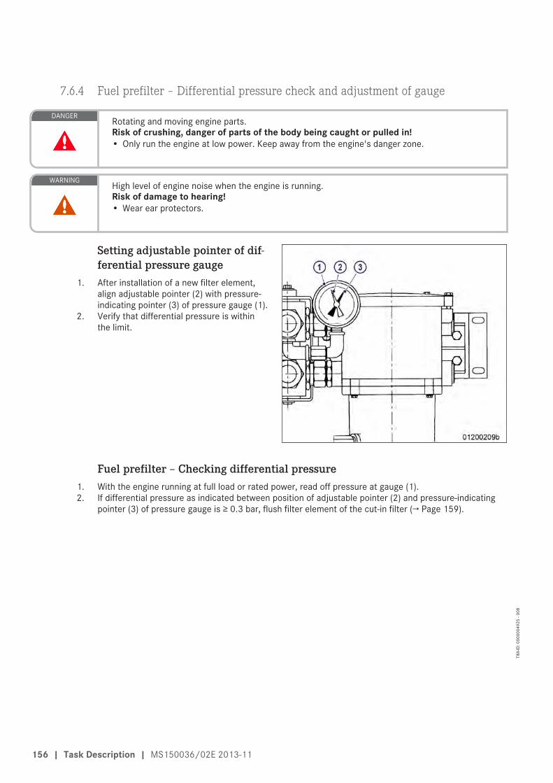
7.6.4 Fuel prefilter – Differential pressure check and adjustment of gauge
DANGER Rotating and moving engine parts.Risk of crushing, danger of parts of the body being caught or pulled in!• Only run the engine at low power. Keep away from the engine's danger zone.
WARNING High level of engine noise when the engine is running.Risk of damage to hearing!• Wear ear protectors.
Setting adjustable pointer of dif-ferential pressure gauge
1. After installation of a new filter element,align adjustable pointer (2) with pressure-indicating pointer (3) of pressure gauge (1).
2. Verify that differential pressure is withinthe limit.
Fuel prefilter – Checking differential pressure1. With the engine running at full load or rated power, read off pressure at gauge (1).2. If differential pressure as indicated between position of adjustable pointer (2) and pressure-indicating
pointer (3) of pressure gauge is ≥ 0.3 bar, flush filter element of the cut-in filter (→ Page 159).
156 | Task Description | MS150036/02E 2013-11
TIM
-ID: 0
0000
0492
5 - 0
08

7.6.5 Fuel prefilter – Draining
Preconditions☑ Engine is stopped and starting disabled.
WARNING Fuels are combustible.Risk of fire and explosion!• Avoid open flames, electrical sparks and ignition sources.• Do not smoke.
Draining fuel prefilter1. Cut out the filter to be replaced (A or B).
1 Filter A cut out2 Filter B cut out
2. Open vent plug (1) of filter to be drained.3. Open drain valve (2).4. Drain water and contaminants from filter
until pure fuel emerges.5. Close drain cock (2).
MS150036/02E 2013-11 | Task Description | 157
TIM
-ID: 0
0000
1851
0 - 0
04

6. Connect filling pump to filling connection(1) on the suction side of the filter.
7. Open vent valve (2) and fill with fuel untilfuel emerges from the vent pipe (3).
8. Close vent valve (2).9. Open rotary slide valve (4) a little (by ap-
prox. 30°) and open vent valve(s) (2), untilfuel emerges from the vent pipe (3).
10. Close vent valve(s) (2).11. Turn rotary slide valve (4) back to locked
position.
158 | Task Description | MS150036/02E 2013-11
TIM
-ID: 0
0000
1851
0 - 0
04

7.6.6 Fuel prefilter – Flushing
Special tools, Material, Spare parts
Designation / Use Part No. Qty.
Diesel fuel
DANGER Rotating and moving engine parts.Risk of crushing, danger of parts of the body being caught or pulled in!• Only run the engine at low power. Keep away from the engine's danger zone.
WARNING Fuels are combustible.Risk of fire and explosion!• Avoid open flames, electrical sparks and ignition sources.• Do not smoke.
WARNING High level of engine noise when the engine is running.Risk of damage to hearing!• Wear ear protectors.
Flushing fuel prefilter1. Cut out dirty filter.
1 Filter A cut out2 Filter B cut out
MS150036/02E 2013-11 | Task Description | 159
TIM
-ID: 0
0000
1272
8 - 0
06

2. Open vent plug (1) of filter to be flushed.3. Open drain valve (2) and drain fuel.
Result: Fuel flows from filtered side back to the un-filtered side, flushing the filter depositsdownwards out of the filter.
4. Close vent plug (1) and drain valve (2).
Fuel prefilter – Filling with fuel1. Stop engine (→ Page 95) and disable engine start.
2. Connect filling pump to filling connection(1) on the suction side of the filter.
3. Open vent valve (2) and fill with fuel untilfuel emerges from the vent pipe (3).
4. Close vent valve (2).5. Open rotary slide valve (4) a little (by ap-
prox. 30°) and open vent valve(s) (2), untilfuel emerges from the vent pipe (3).
6. Close vent valve(s) (2).7. Turn rotary slide valve (4) back to locked
position.8. Check differential pressure (→ Page 156).
Result: Replace filter element in fuel prefilter(→ Page 161) if flushing did not improve dif-ferential pressure.
160 | Task Description | MS150036/02E 2013-11
TIM
-ID: 0
0000
1272
8 - 0
06
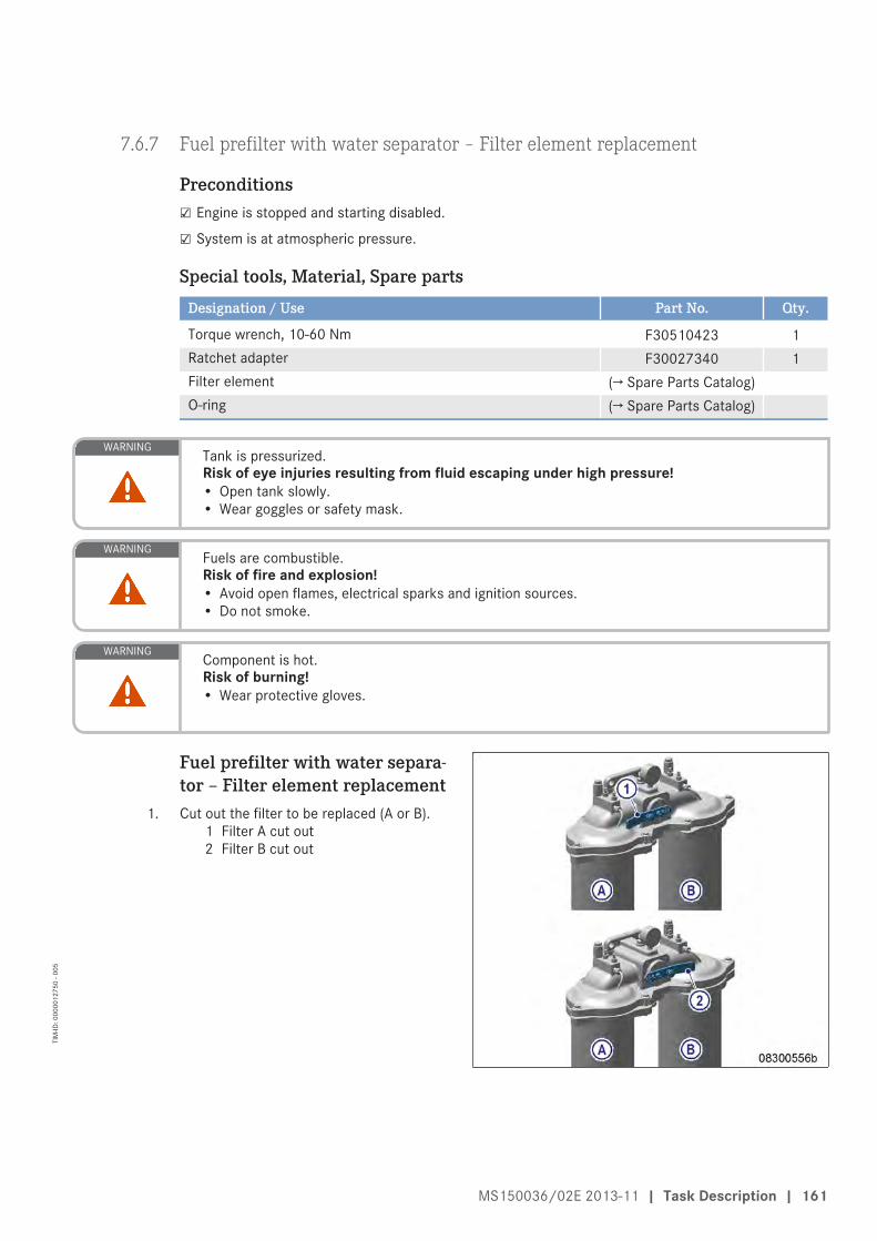
7.6.7 Fuel prefilter with water separator – Filter element replacement
Preconditions☑ Engine is stopped and starting disabled.
☑ System is at atmospheric pressure.
Special tools, Material, Spare parts
Designation / Use Part No. Qty.
Torque wrench, 10-60 Nm F30510423 1Ratchet adapter F30027340 1Filter element (→ Spare Parts Catalog)O-ring (→ Spare Parts Catalog)
WARNING Tank is pressurized.Risk of eye injuries resulting from fluid escaping under high pressure!• Open tank slowly.• Wear goggles or safety mask.
WARNING Fuels are combustible.Risk of fire and explosion!• Avoid open flames, electrical sparks and ignition sources.• Do not smoke.
WARNING Component is hot.Risk of burning!• Wear protective gloves.
Fuel prefilter with water separa-tor – Filter element replacement
1. Cut out the filter to be replaced (A or B).1 Filter A cut out2 Filter B cut out
MS150036/02E 2013-11 | Task Description | 161
TIM
-ID: 0
0000
1275
0 - 0
05
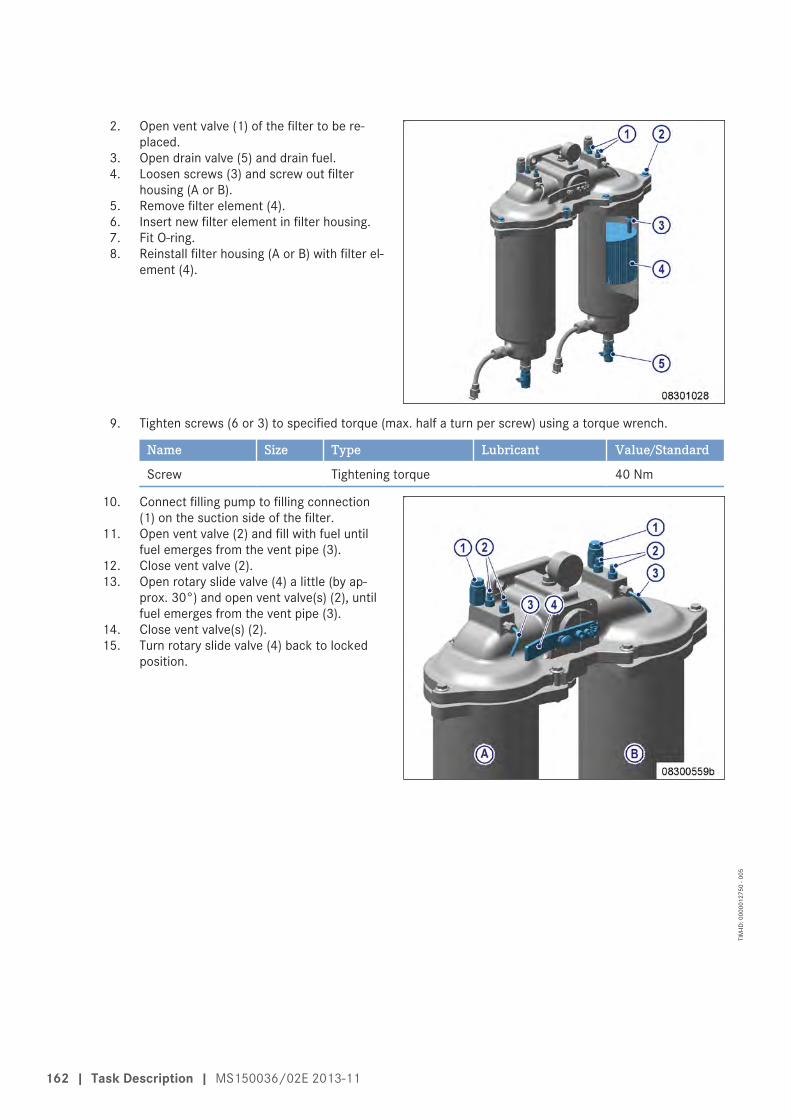
2. Open vent valve (1) of the filter to be re-placed.
3. Open drain valve (5) and drain fuel.4. Loosen screws (3) and screw out filter
housing (A or B).5. Remove filter element (4).6. Insert new filter element in filter housing.7. Fit O-ring.8. Reinstall filter housing (A or B) with filter el-
ement (4).
9. Tighten screws (6 or 3) to specified torque (max. half a turn per screw) using a torque wrench.
Name Size Type Lubricant Value/Standard
Screw Tightening torque 40 Nm
10. Connect filling pump to filling connection(1) on the suction side of the filter.
11. Open vent valve (2) and fill with fuel untilfuel emerges from the vent pipe (3).
12. Close vent valve (2).13. Open rotary slide valve (4) a little (by ap-
prox. 30°) and open vent valve(s) (2), untilfuel emerges from the vent pipe (3).
14. Close vent valve(s) (2).15. Turn rotary slide valve (4) back to locked
position.
162 | Task Description | MS150036/02E 2013-11
TIM
-ID: 0
0000
1275
0 - 0
05

7.7 Exhaust Turbocharger
7.7.1 Compressor wheel – Cleaning
Preconditions☑ Engine is stopped and starting disabled
Special tools, Material, Spare parts
Designation / Use Part No. Qty.
Torque wrench, 10-60 Nm F30452769 1Ratchet adapter F30027340 1Cleaning agent 40377 1Engine oilEngine coolantSealing rings (→ Spare Parts Catalog) 3Sealing rings (→ Spare Parts Catalog) 4
WARNING Chemical substances.Risk of irritation and chemical burns!• Always obey manufacturer's instructions for use!
CAUTION Incorrect installation of components and lines.Damage to component!• Ensure that components/lines are installed so that they are never under tension or strain.• Ensure correct installation position of components.
CAUTION Unsuitable cleaning tool.Damage to component!• Observe manufacturer's instructions.• Use appropriate cleaning tool.
Preparatory steps – Horizontal air intake1. Drain engine coolant (→ Page 194).2. Remove air filter (→ Page 173).3. Seal all openings with suitable covers.
MS150036/02E 2013-11 | Task Description | 163
TIM
-ID: 0
0000
1862
9 - 0
05

4. Remove charge-air pipework (1) from ex-haust turbocharger to intercooler.
5. Remove oil lines (2).
6. Loosen clamp (1).7. Remove intake housing (3) with actuating
cylinder (2).
8. Remove coolant lines (1) from compressorhousing (3).
9. Remove coolant ventilation line (2) fromcompressor housing (3).
164 | Task Description | MS150036/02E 2013-11
TIM
-ID: 0
0000
1862
9 - 0
05

10. Undo screws (1).11. Remove compressor housing (2).
Cleaning compressor wheelNote: Do not use wire brush, scraper or similar
tools for cleaning!1. Clean compressor housing with a smooth
paint brush or brush.2. Clean compressor wheel (2) and bearing
housing (1).3. Thoroughly remove cleaner from all compo-
nents.4. Fit new sealing rings between bearing
housing/compressor housing and plug-insleeves if necessary.
Final steps – Horizontal air in-take
1. Install compressor housing (2).
MS150036/02E 2013-11 | Task Description | 165
TIM
-ID: 0
0000
1862
9 - 0
05
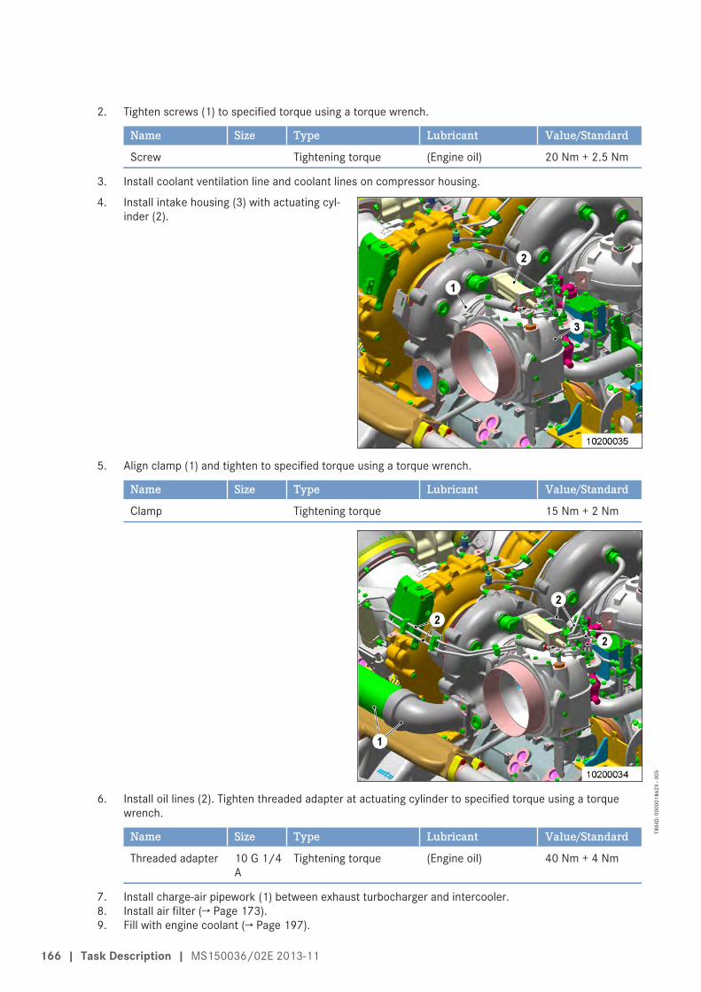
2. Tighten screws (1) to specified torque using a torque wrench.
Name Size Type Lubricant Value/Standard
Screw Tightening torque (Engine oil) 20 Nm + 2.5 Nm
3. Install coolant ventilation line and coolant lines on compressor housing.
4. Install intake housing (3) with actuating cyl-inder (2).
5. Align clamp (1) and tighten to specified torque using a torque wrench.
Name Size Type Lubricant Value/Standard
Clamp Tightening torque 15 Nm + 2 Nm
6. Install oil lines (2). Tighten threaded adapter at actuating cylinder to specified torque using a torquewrench.
Name Size Type Lubricant Value/Standard
Threaded adapter 10 G 1/4A
Tightening torque (Engine oil) 40 Nm + 4 Nm
7. Install charge-air pipework (1) between exhaust turbocharger and intercooler.8. Install air filter (→ Page 173).9. Fill with engine coolant (→ Page 197).
166 | Task Description | MS150036/02E 2013-11
TIM
-ID: 0
0000
1862
9 - 0
05

Preparatory steps – Vertical air intake1. Drain engine coolant (→ Page 194).2. Remove air filter (→ Page 173).3. Seal all openings with suitable covers.
4. Remove charge-air pipework (1) from ex-haust turbocharger to intercooler.
5. Remove oil lines (2).
6. Loosen clamp (1).7. Remove intake housing (3) with actuating
cylinder (2).
MS150036/02E 2013-11 | Task Description | 167
TIM
-ID: 0
0000
1862
9 - 0
05

8. Remove coolant lines (1) from compressorhousing (3).
9. Remove coolant ventilation line (2) fromcompressor housing (3).
10. Undo screws (1).11. Remove compressor housing (2).
Cleaning compressor wheelNote: Do not use wire brush, scraper or similar
tools for cleaning!1. Clean compressor housing with a smooth
paint brush or brush.2. Clean compressor wheel (2) and bearing
housing (1).3. Thoroughly remove cleaner from all compo-
nents.4. Fit new sealing rings between bearing
housing/compressor housing and plug-insleeves if necessary.
168 | Task Description | MS150036/02E 2013-11
TIM
-ID: 0
0000
1862
9 - 0
05

Final steps – Vertical air intake1. Install compressor housing (2).
2. Tighten screws (1) to specified torque using a torque wrench.
Name Size Type Lubricant Value/Standard
Screw Tightening torque (Engine oil) 20 Nm + 2.5 Nm
3. Install coolant ventilation line and coolant lines on compressor housing.
4. Install intake housing (3) with actuating cyl-inder (2).
5. Align clamp (1) and tighten to specified torque using a torque wrench.
Name Size Type Lubricant Value/Standard
Clamp Tightening torque 15 Nm + 2 Nm
MS150036/02E 2013-11 | Task Description | 169
TIM
-ID: 0
0000
1862
9 - 0
05

6. Install oil lines (2). Tighten threaded adapter at actuating cylinder to specified torque using a torquewrench.
Name Size Type Lubricant Value/Standard
Threaded adapter 10 G 1/4A
Tightening torque (Engine oil) 40 Nm + 4 Nm
7. Install charge-air pipework (1) between exhaust turbocharger and intercooler.8. Install air filter (→ Page 173).9. Fill with engine coolant (→ Page 197).
170 | Task Description | MS150036/02E 2013-11
TIM
-ID: 0
0000
1862
9 - 0
05
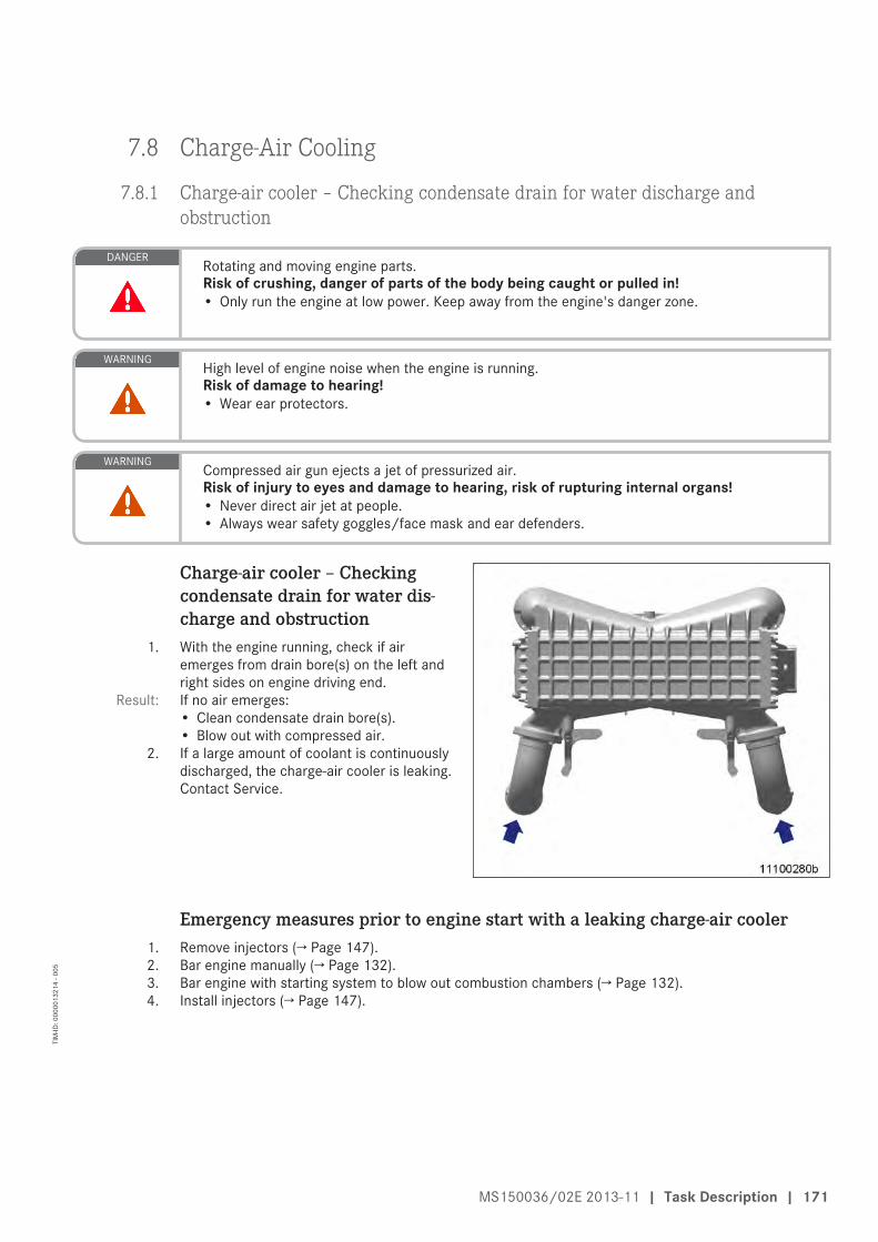
7.8 Charge-Air Cooling
7.8.1 Charge-air cooler – Checking condensate drain for water discharge andobstruction
DANGER Rotating and moving engine parts.Risk of crushing, danger of parts of the body being caught or pulled in!• Only run the engine at low power. Keep away from the engine's danger zone.
WARNING High level of engine noise when the engine is running.Risk of damage to hearing!• Wear ear protectors.
WARNING Compressed air gun ejects a jet of pressurized air.Risk of injury to eyes and damage to hearing, risk of rupturing internal organs!• Never direct air jet at people.• Always wear safety goggles/face mask and ear defenders.
Charge-air cooler – Checkingcondensate drain for water dis-charge and obstruction
1. With the engine running, check if airemerges from drain bore(s) on the left andright sides on engine driving end.
Result: If no air emerges:• Clean condensate drain bore(s).• Blow out with compressed air.
2. If a large amount of coolant is continuouslydischarged, the charge-air cooler is leaking.Contact Service.
Emergency measures prior to engine start with a leaking charge-air cooler1. Remove injectors (→ Page 147).2. Bar engine manually (→ Page 132).3. Bar engine with starting system to blow out combustion chambers (→ Page 132).4. Install injectors (→ Page 147).
MS150036/02E 2013-11 | Task Description | 171
TIM
-ID: 0
0000
1321
4 - 0
05

7.9 Air Filter
7.9.1 Air filter – Replacement
Special tools, Material, Spare parts
Designation / Use Part No. Qty.
Air filter (→ Spare Parts Catalog)
Replacing the air filter1. Remove old air filter and install new air filter (→ Page 173).2. Reset signal ring of contamination indicator (→ Page 174).
172 | Task Description | MS150036/02E 2013-11
TIM
-ID: 0
0000
0544
7 - 0
09

7.9.2 Air filter – Removal and installation
Preconditions☑ Engine is stopped and starting disabled.
Air filter1. Loosen clamp (2).2. Remove air filter (1) and clamp (2) from
connecting flange of housing (3).3. Verify that there are no objects in the
flange of the intake housing (3) and cleanit.
4. Attach air filter (1) with clamp (2) onto in-take housing (3).
5. Tighten clamp (2).
Air filter with intake silencer1. Loosen clamp (2).2. Remove air filter (1) and clamp (2) from in-
take silencer (3).3. Clean intake silencer (3) and check for ob-
structions.4. Attach air filter (1) with clamp (2) onto in-
take silencer (1).5. Tighten clamp (2).
MS150036/02E 2013-11 | Task Description | 173
TIM
-ID: 0
0000
1340
1 - 0
07

7.10 Air Intake
7.10.1 Service indicator – Signal ring position check (optional)
Preconditions☑ Engine is stopped and starting disabled.
Checking signal ring position1. If the signal ring is completely visible in the
control window (2), replace air filter(→ Page 172).
2. After installation of new filter, press resetbutton (1).
Result: Engaged piston with signal ring movesback to initial position.
174 | Task Description | MS150036/02E 2013-11
TIM
-ID: 0
0000
0548
4 - 0
08
7.11 Starting Equipment
7.11.1 Starter – Condition check
Preconditions☑ Engine is stopped and starting disabled.
Checking starter condition1. Check securing screws of starter for secure seating and tighten if required.2. Check wiring (→ Page 224).
MS150036/02E 2013-11 | Task Description | 175
TIM
-ID: 0
0000
0090
5 - 0
17

7.12 Lube Oil System, Lube Oil Circuit
7.12.1 Engine oil – Level check
Preconditions☑ Engine is stopped and starting disabled.
Oil level check prior to enginestart
1. Withdraw dipstick from guide tube andwipe it.
2. Insert dipstick into guide tube to stop,withdraw after approx. 10 seconds andcheck oil level.
Note: After extended standstill, the oil level mayexceed the mark (1) by up to 2 cm. Thiscan be caused by oil flowing from e.g. oilfilter or heat exchanger back to the oil pan.
3. The oil level must reach mark (1) or exceedmark (1) by up to 2 cm.
4. Top up with oil to mark (1) as necessary(→ Page 177).
5. Insert dipstick into guide tube up to thestop.
Oil level check after the engine is stopped1. 5 minutes after stopping the engine, remove oil dipstick from the guide tube and wipe it.2. Insert dipstick into guide tube to stop, withdraw after approx. 10 seconds and check oil level.3. Oil level must be between marks (1) and (2).4. Top up with oil to mark (1) as necessary (→ Page 177).5. Insert dipstick into guide tube up to the stop.
176 | Task Description | MS150036/02E 2013-11
TIM
-ID: 0
0000
0093
1 - 0
11

7.12.2 Engine oil – Change
Preconditions☑ Engine is stopped and starting disabled.
☑ Engine is at operating temperature.
☑ MTU Fluids and Lubricants Specifications (A001061/..) are available.
Special tools, Material, Spare parts
Designation / Use Part No. Qty.
Torque wrench, 40-200 Nm F30027337 1Ratchet adapter F30027341 1Engine oilSealing ring (→ Spare Parts Catalog)
WARNING Hot oil.Oil can contain combustion residues which are harmful to health.Risk of injury and poisoning!• Wear protective clothing, gloves, and goggles / safety mask.• Avoid contact with skin.• Do not inhale oil vapor.
Oil change without semirotary hand pump: Draining oil via drain plug(s) on oilpan
1. Provide a suitable container to collect the oil.2. Remove drain plug(s) and drain oil.3. Install drain plug(s) with new sealing ring.
Oil change with semirotary hand pump: Oil extraction1. Provide a suitable container to collect the oil.2. Draw all oil from oil pan using the semirotary hand pump.
Draining residual oil at gearcase1. Provide a suitable container to collect the
oil.2. Remove drain plugs (1) and (2) and drain
oil:• Approx. 12 liters at (1)• Approx. 5 liters at (2)
3. Install drain plug(s) with new sealing ring.
MS150036/02E 2013-11 | Task Description | 177
TIM
-ID: 0
0000
1409
9 - 0
03

4. Tighten drain plugs (1) and (2) to specified torque using a torque wrench:
Name Size Type Lubricant Value/Standard
Screw M26x1.5 Tightening torque (Engine oil) 100 Nm+10 Nm
Filling with new oil1. Open cap on filler neck.2. Pour oil in at filler neck up to 'max.' mark
at oil dipstick.3. Close cap on filler neck.4. Check engine oil level (→ Page 176).5. Turn engine with starting system after oil
change (→ Page 134).
178 | Task Description | MS150036/02E 2013-11
TIM
-ID: 0
0000
1409
9 - 0
03

7.12.3 Engine oil – Sample extraction and analysis
Preconditions☑ MTU Fluids and Lubricants Specifications (A001061/..) are available.
Special tools, Material, Spare parts
Designation / Use Part No. Qty.
MTU test kit 5605892099/00 1
DANGER Rotating and moving engine parts.Risk of crushing, danger of parts of the body being caught or pulled in!• Only run the engine at low power. Keep away from the engine's danger zone.
WARNING Hot oil.Oil can contain combustion residues which are harmful to health.Risk of injury and poisoning!• Wear protective clothing, gloves, and goggles / safety mask.• Avoid contact with skin.• Do not inhale oil vapor.
WARNING High level of engine noise when the engine is running.Risk of damage to hearing!• Wear ear protectors.
Engine oil – Sample extractionand analysis
1. With the engine running at operating tem-perature, open screw on centrifugal oil fil-ter carrier by 1 to 2 rotations.
2. Drain approx. 2 liters engine oil to flush outthe oil sludge.
3. Drain approx. 1 liter engine oil into a cleancontainer.
4. Close screw.5. Using the equipment and chemicals in the
MTU test kit, analyze the engine oil for:• Dispersion capability (spot test);• Water content;• Dilution by fuel.
MS150036/02E 2013-11 | Task Description | 179
TIM
-ID: 0
0000
1411
3 - 0
05

Engine oil – Sample extractionand analysis (engines withswitchable oil filter)
1. With the engine running at operating tem-perature, open screw on flange of centrifu-gal oil filter by 1 to 2 rotations.
2. Drain approx. 2 liters engine oil to flush outthe oil sludge.
3. Drain approx. 1 liter engine oil into a cleancontainer.
4. Close screw.5. Using the equipment and chemicals in the
MTU test kit, analyze the engine oil for:• Dispersion capability (spot test);• Water content;• Dilution by fuel.
180 | Task Description | MS150036/02E 2013-11
TIM
-ID: 0
0000
1411
3 - 0
05
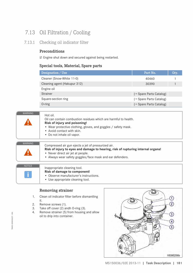
7.13 Oil Filtration / Cooling
7.13.1 Checking oil indicator filter
Preconditions☑ Engine shut down and secured against being restarted.
Special tools, Material, Spare parts
Designation / Use Part No. Qty.
Cleaner (Snow-White 11-0) 40460 1Cleaning agent (Hakupur 312) 30390 1Engine oilStrainer (→ Spare Parts Catalog)Square-section ring (→ Spare Parts Catalog)O-ring (→ Spare Parts Catalog)
WARNING Hot oil.Oil can contain combustion residues which are harmful to health.Risk of injury and poisoning!• Wear protective clothing, gloves, and goggles / safety mask.• Avoid contact with skin.• Do not inhale oil vapor.
WARNING Compressed air gun ejects a jet of pressurized air.Risk of injury to eyes and damage to hearing, risk of rupturing internal organs!• Never direct air jet at people.• Always wear safety goggles/face mask and ear defenders.
NOTICE Inappropriate cleaning tool.Risk of damage to component!• Observe manufacturer's instructions.• Use appropriate cleaning tool.
Removing strainer1. Clean oil indicator filter before dismantling
it.2. Remove screws (1).3. Take off cover (2) andh O-ring (3).4. Remove strainer (5) from housing and allow
oil to drip into container.
MS150036/02E 2013-11 | Task Description | 181
TIM
-ID: 0
0000
3622
7 - 0
04

Cleaning strainer1. Shake coarse contamination out of strainer (5).2. Clean all metallic parts with cleaner (Snow-White 11-0), then rinse with cleaner (Hakupur 312).3. Use a soft brush to remove stubborn deposits from strainer if required. When doing so, take care not to
damage the mesh.4. Blow out strainer (5) with compressed air from inside.
Checking strainerItem Findings ActionStrainer Metallic residues • Clean
• Monitor engine operation• Check strainer daily• Notify Service
Strainer Damaged Fit new partSquare-section ring Damaged Fit new partO-ring Damaged Fit new part
Installing strainer1. Coat square-section ring (4) on strainer (5) with engine oil and install strainer (5).2. Insert strainer into housing.3. Fill housing with new engine oil.4. Coat O-ring (3) with engine oil and fit in filter housing.5. Fit cover (2) and secure with screws (1) and washers.
182 | Task Description | MS150036/02E 2013-11
TIM
-ID: 0
0000
3622
7 - 0
04

7.13.2 Engine oil filter – Replacement
Special tools, Material, Spare parts
Designation / Use Part No. Qty.
Filter wrench F30379104Engine oilOil filter (→ Spare Parts Catalog)
DANGER Rotating and moving engine parts.Risk of crushing, danger of parts of the body being caught or pulled in!• Only run the engine at low power. Keep away from the engine's danger zone.
WARNING High level of engine noise when the engine is running.Risk of damage to hearing!• Wear ear protectors.
WARNING Hot oil.Oil can contain combustion residues which are harmful to health.Risk of injury and poisoning!• Wear protective clothing, gloves, and goggles / safety mask.• Avoid contact with skin.• Do not inhale oil vapor.
NOTICE Damage to component!Severe material damage!• For filter replacement with the engine running, operate the engine at low engine load.• The filter which is to be replaced must be cut out for a brief period only.
Replacing engine oil filter1. Stop engine (→ Page 95) and disable en-
gine start.2. Unscrew oil filter using filter wrench.3. Clean sealing surface on connecting piece.4. Check condition of new oil filter sealing
ring and moisten it with oil.5. Screw on and tighten new oil filter by hand.6. Replace other oil filters in the same way.7. Turn engine with starting system after ev-
ery oil change and filter replacement(→ Page 134).
8. Check oil level (→ Page 176).
MS150036/02E 2013-11 | Task Description | 183
TIM
-ID: 0
0000
1423
8 - 0
05

Oil filter with diverter (option):Oil filter replacement with theengine stopped
1. Stop engine (→ Page 95) and disable en-gine start.
2. Unscrew oil filter using oil filter wrench.3. Clean sealing surface on connecting piece.4. Check condition of new oil filter sealing
ring and moisten it with oil.5. Fit SOLAS shield (→ Page 15).6. Screw on and tighten new oil filter by hand.7. Replace other oil filters in the same way.8. Turn engine with starting system after ev-
ery oil change and filter replacement(→ Page 134).
9. Check oil level (→ Page 176).
Oil filter with diverter (option):Oil filter replacement with theengine running
1. To cut out the filter to be replaced, set thethree-way cock to the corresponding posi-tion.• Position A: Lower filters cut out• Position B: Both filters cut in (normal op-
erating position)• Position C: Upper filters cut out.
2. Unscrew oil filter using oil filter wrench.3. Clean sealing surface on connecting piece.4. Check condition of new oil filter sealing
ring and moisten it with oil.5. Fit SOLAS shield (→ Page 15).6. Screw on and tighten new oil filter by hand.7. Replace other oil filters in the same way.8. Check oil level (→ Page 176).
184 | Task Description | MS150036/02E 2013-11
TIM
-ID: 0
0000
1423
8 - 0
05
7.13.3 Centrifugal oil filter – Cleaning and filter sleeve replacement
Preconditions☑ Engine is stopped and starting disabled.
Special tools, Material, Spare parts
Designation / Use Part No. Qty.
Torque wrench, 6-50 Nm F30027336 1Filter wrench F30379104 1Cleaner Hakutex 60Grease (Kluthe Hakuform 30-10/emulsifier) X00029933 1Filter sleeve (→ Spare Parts Catalog)Sealing ring (→ Spare Parts Catalog)Sealing ring (→ Spare Parts Catalog)Sealing ring (→ Spare Parts Catalog)
WARNING Hot oil.Oil can contain combustion residues which are harmful to health.Risk of injury and poisoning!• Wear protective clothing, gloves, and goggles / safety mask.• Avoid contact with skin.• Do not inhale oil vapor.
WARNING Compressed air gun ejects a jet of pressurized air.Risk of injury to eyes and damage to hearing, risk of rupturing internal organs!• Never direct air jet at people.• Always wear safety goggles/face mask and ear defenders.
MS150036/02E 2013-11 | Task Description | 185
TIM
-ID: 0
0000
1425
6 - 0
04

Centrifugal oil filter – Cleaningand filter sleeve replacement
1. Remove clamp (14).2. Release Tommy nut (2) and take off cov-
er (1).3. Carefully lift rotor (11), allow oil to drain
and remove from housing.4. Holding the rotor (11) firmly, release rotor
cover nut (3).5. Take off rotor cover (4).6. Remove filter sleeve (6).7. Measure layer thickness of oil residues on
filter sleeve (6).Result: If the oil residues exceed the maximum lay-
er thickness of 45 mm, shorten the mainte-nance interval.
8. Disassemble rotor tube (7), conical disk (8)and rotor base (10).
9. Wash rotor cover (4), rotor tube (7), conicaldisk (8) and rotor base (10) with coldcleaner.
10. Blow out with compressed air.11. Check sealing ring (9), fit new one if neces-
sary.12. Assemble rotor tube (7), conical disk (8)
and rotor base (10) with sealing ring (9).13. Insert new filter sleeve (6) in rotor tube (7)
with the smooth paper surface facing theouter wall.
14. Check sealing ring (5), fit new one if neces-sary.
15. Mount rotor cover (4) with sealing ring (5).
16. Tighten rotor cover nut (3) with torque wrench to the specified torque.
Name Size Type Lubricant Value/Standard
Nut Tightening torque 35 Nm to 45 Nm
17. Place rotor (11) in housing (12) and check for ease of movement.18. Check sealing ring (13), fit new one if necessary.19. Fit sealing ring (13) on housing (12).20. Fit hood (1).21. Tighten Tommy nut (2) by hand.
22. Install clamp (14) and tighten with torque wrench to the specified torque.
Name Size Type Lubricant Value/Standard
Clamp Tightening torque 8 Nm to 10 Nm
23. Tighten cover nut (2) with torque wrench to the specified torque.
Name Size Type Lubricant Value/Standard
Screw Tightening torque 5 Nm to 7 Nm
186 | Task Description | MS150036/02E 2013-11
TIM
-ID: 0
0000
1425
6 - 0
04
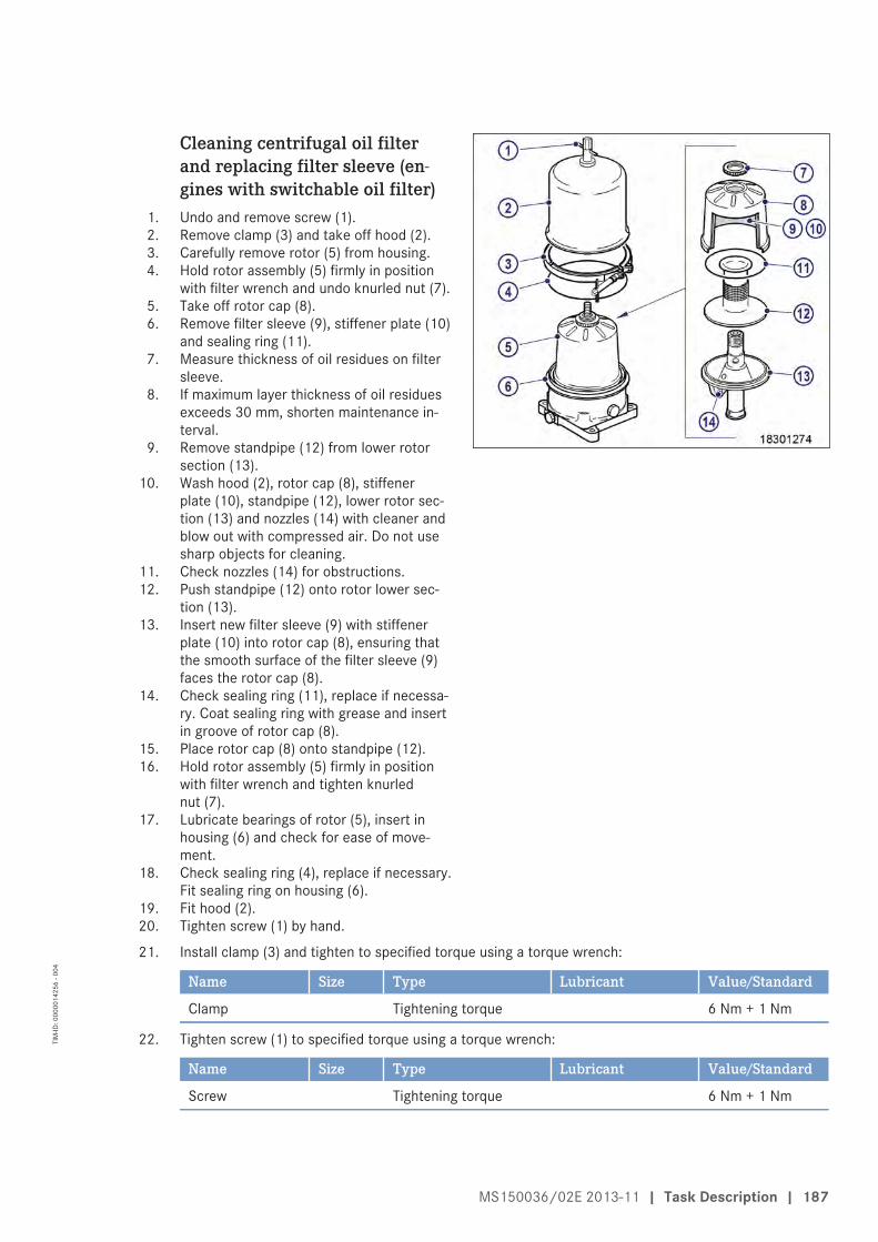
Cleaning centrifugal oil filterand replacing filter sleeve (en-gines with switchable oil filter)
1. Undo and remove screw (1).2. Remove clamp (3) and take off hood (2).3. Carefully remove rotor (5) from housing.4. Hold rotor assembly (5) firmly in position
with filter wrench and undo knurled nut (7).5. Take off rotor cap (8).6. Remove filter sleeve (9), stiffener plate (10)
and sealing ring (11).7. Measure thickness of oil residues on filter
sleeve.8. If maximum layer thickness of oil residues
exceeds 30 mm, shorten maintenance in-terval.
9. Remove standpipe (12) from lower rotorsection (13).
10. Wash hood (2), rotor cap (8), stiffenerplate (10), standpipe (12), lower rotor sec-tion (13) and nozzles (14) with cleaner andblow out with compressed air. Do not usesharp objects for cleaning.
11. Check nozzles (14) for obstructions.12. Push standpipe (12) onto rotor lower sec-
tion (13).13. Insert new filter sleeve (9) with stiffener
plate (10) into rotor cap (8), ensuring thatthe smooth surface of the filter sleeve (9)faces the rotor cap (8).
14. Check sealing ring (11), replace if necessa-ry. Coat sealing ring with grease and insertin groove of rotor cap (8).
15. Place rotor cap (8) onto standpipe (12).16. Hold rotor assembly (5) firmly in position
with filter wrench and tighten knurlednut (7).
17. Lubricate bearings of rotor (5), insert inhousing (6) and check for ease of move-ment.
18. Check sealing ring (4), replace if necessary.Fit sealing ring on housing (6).
19. Fit hood (2).20. Tighten screw (1) by hand.
21. Install clamp (3) and tighten to specified torque using a torque wrench:
Name Size Type Lubricant Value/Standard
Clamp Tightening torque 6 Nm + 1 Nm
22. Tighten screw (1) to specified torque using a torque wrench:
Name Size Type Lubricant Value/Standard
Screw Tightening torque 6 Nm + 1 Nm
MS150036/02E 2013-11 | Task Description | 187
TIM
-ID: 0
0000
1425
6 - 0
04

7.14 Coolant Circuit, General, High-Temperature Circuit
7.14.1 Drain and vent points
Coolant line on ETC
1 Vent point
Coolant line to intercooler
1 Vent point
188 | Task Description | MS150036/02E 2013-11
TIM
-ID: 0
0000
1454
5 - 0
03

1 Vent point
Coolant line to raw water cooler
1 Vent point
MS150036/02E 2013-11 | Task Description | 189
TIM
-ID: 0
0000
1454
5 - 0
03

Vent line – Distribution cross
1 Vent point
Coolant drain point, engine driving end
1 Drain point
190 | Task Description | MS150036/02E 2013-11
TIM
-ID: 0
0000
1454
5 - 0
03

Coolant drain point, engine free end
1 Drain point
MS150036/02E 2013-11 | Task Description | 191
TIM
-ID: 0
0000
1454
5 - 0
03

7.14.2 Engine coolant level – Check
Preconditions☑ Engine is stopped and starting disabled.
☑ MTU Fluids and Lubricants Specifications (A001061/..) are available.
WARNING Coolant is hot and under pressure.Risk of injury and scalding!• Let the engine cool down.• Wear protective clothing, gloves, and goggles / safety mask.
Checking engine coolant level at filler neck:1. Turn breather valve on coolant expansion tank (for engines with remote heat exchanger: the expansion
tank is part of the remote cooling system) counterclockwise up to the first stop and allow pressure toescape.
2. Continue to turn breather valve counterclockwise and remove.3. Check coolant level (coolant must be visible at the bottom edge of the cast-in eye in the filler neck).
Checking engine coolant level atexternal cooler:
1. Check coolant level (coolant must be visi-ble at marker plate).
2. Top up with treated coolant as necessary(→ Page 197).
3. Check and clean breather valve.4. Set breather valve onto filler neck and
close it.
Checking engine coolant level by means of level sensor:1. Switch on engine control system and check readings on the display.2. Top up with treated coolant as necessary (→ Page 197).
192 | Task Description | MS150036/02E 2013-11
TIM
-ID: 0
0000
1460
5 - 0
03

7.14.3 Engine coolant – Change
Special tools, Material, Spare parts
Designation / Use Part No. Qty.
Coolant
Engine coolant change1. Drain engine coolant (→ Page 194).2. Fill with engine coolant (→ Page 197).
MS150036/02E 2013-11 | Task Description | 193
TIM
-ID: 0
0000
0003
6 - 0
31

7.14.4 Engine coolant – Draining
Preconditions☑ Engine is stopped and starting disabled.
WARNING Coolant is hot and under pressure.Risk of injury and scalding!• Let the engine cool down.• Wear protective clothing, gloves, and goggles / safety mask.
Preparatory steps1. Provide an appropriate container to drain the coolant into.2. Switch off preheating unit.
Engine coolant – Draining1. Turn breather valve on expansion tank (for engines with remote heat exchanger: the expansion tank is
part of the remote cooling system) counterclockwise up to the first stop and allow pressure to escape.2. Continue to turn breather valve counterclockwise and remove.3. Draw off precipitated corrosion inhibitor oil from the expansion tank through filler neck.
4. Open vent valves on carrier housing (1).
194 | Task Description | MS150036/02E 2013-11
TIM
-ID: 0
0000
1459
3 - 0
05
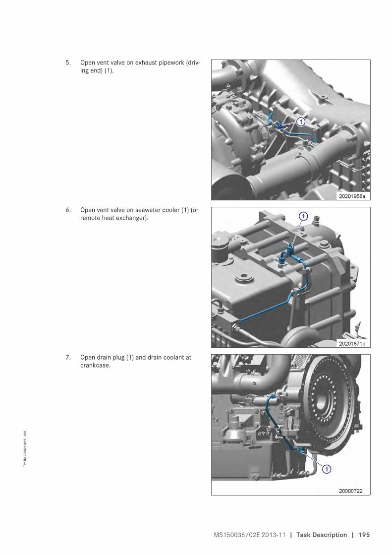
5. Open vent valve on exhaust pipework (driv-ing end) (1).
6. Open vent valve on seawater cooler (1) (orremote heat exchanger).
7. Open drain plug (1) and drain coolant atcrankcase.
MS150036/02E 2013-11 | Task Description | 195
TIM
-ID: 0
0000
1459
3 - 0
05

8. Open drain screw (1) and drain coolant oncoolant pump elbow.
Final steps1. Seal all open vent and drain points.2. Set breather valve onto filler neck and close it.
196 | Task Description | MS150036/02E 2013-11
TIM
-ID: 0
0000
1459
3 - 0
05

7.14.5 Engine coolant – Filling
Preconditions☑ Engine is stopped and starting disabled.
☑ MTU Fluids and Lubricants Specifications (A001061/..) are available.
Special tools, Material, Spare parts
Designation / Use Part No. Qty.
Engine coolant
WARNING Coolant is hot and under pressure.Risk of injury and scalding!• Let the engine cool down.• Wear protective clothing, gloves, and goggles / safety mask.
NOTICE Cold coolant in hot engine can cause thermal stress.Possible formation of cracks in the engine!• Fill / top up coolant only into cold engine.
Preparatory steps1. Turn breather valve on expansion tank (for
engines with remote heat exchanger: theexpansion tank is part of the remote cool-ing system) counterclockwise up to thefirst stop and allow pressure to escape.
2. Continue to turn breather valve counter-clockwise and remove.
MS150036/02E 2013-11 | Task Description | 197
TIM
-ID: 0
0000
1456
9 - 0
05
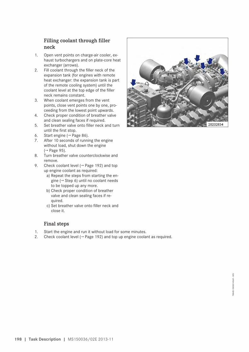
Filling coolant through fillerneck
1. Open vent points on charge-air cooler, ex-haust turbochargers and on plate-core heatexchanger (arrows).
2. Fill coolant through the filler neck of theexpansion tank (for engines with remoteheat exchanger: the expansion tank is partof the remote cooling system) until thecoolant level at the top edge of the fillerneck remains constant.
3. When coolant emerges from the ventpoints, close vent points one by one, pro-ceeding from the lowest point upwards.
4. Check proper condition of breather valveand clean sealing faces if required.
5. Set breather valve onto filler neck and turnuntil the first stop.
6. Start engine (→ Page 86).7. After 10 seconds of running the engine
without load, shut down the engine(→ Page 95).
8. Turn breather valve counterclockwise andremove.
9. Check coolant level (→ Page 192) and topup engine coolant as required:
a) Repeat the steps from starting the en-gine (→ Step 6) until no coolant needsto be topped up any more.
b) Check proper condition of breathervalve and clean sealing faces if re-quired.
c) Set breather valve onto filler neck andclose it.
Final steps1. Start the engine and run it without load for some minutes.2. Check coolant level (→ Page 192) and top up engine coolant as required.
198 | Task Description | MS150036/02E 2013-11
TIM
-ID: 0
0000
1456
9 - 0
05

7.14.6 HT coolant pump – Relief bore check
DANGER Rotating and moving engine parts.Risk of crushing, danger of parts of the body being caught or pulled in!• Only run the engine at low power. Keep away from the engine's danger zone.
WARNING High level of engine noise when the engine is running.Risk of damage to hearing!• Wear ear protectors.
HT coolant pump – Relief borecheck
1. Check relief bore for oil and coolant dis-charge.
2. Stop engine (→ Operating instructions elec-tronic system) and disable engine start.
3. Clean the relief bore with a wire if it isdirty.• Permissible engine coolant discharge:
up to 10 drops per hour;• Permissible oil discharge: up to 5 drops
per hour.4. If discharge exceeds the specified limits,
contact Service.
MS150036/02E 2013-11 | Task Description | 199
TIM
-ID: 0
0000
0680
3 - 0
04
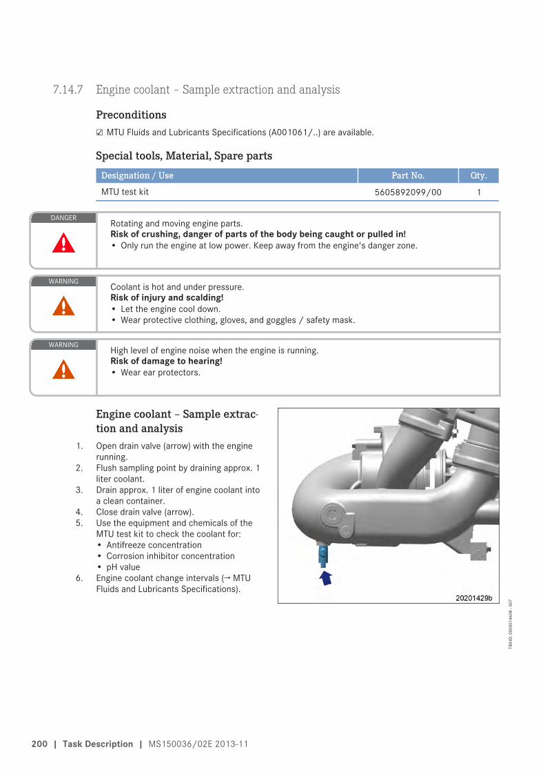
7.14.7 Engine coolant – Sample extraction and analysis
Preconditions☑ MTU Fluids and Lubricants Specifications (A001061/..) are available.
Special tools, Material, Spare parts
Designation / Use Part No. Qty.
MTU test kit 5605892099/00 1
DANGER Rotating and moving engine parts.Risk of crushing, danger of parts of the body being caught or pulled in!• Only run the engine at low power. Keep away from the engine's danger zone.
WARNING Coolant is hot and under pressure.Risk of injury and scalding!• Let the engine cool down.• Wear protective clothing, gloves, and goggles / safety mask.
WARNING High level of engine noise when the engine is running.Risk of damage to hearing!• Wear ear protectors.
Engine coolant – Sample extrac-tion and analysis
1. Open drain valve (arrow) with the enginerunning.
2. Flush sampling point by draining approx. 1liter coolant.
3. Drain approx. 1 liter of engine coolant intoa clean container.
4. Close drain valve (arrow).5. Use the equipment and chemicals of the
MTU test kit to check the coolant for:• Antifreeze concentration• Corrosion inhibitor concentration• pH value
6. Engine coolant change intervals (→ MTUFluids and Lubricants Specifications).
200 | Task Description | MS150036/02E 2013-11
TIM
-ID: 0
0000
1460
8 - 0
07

7.14.8 Engine coolant filter – Replacement
Preconditions☑ Engine is stopped and starting disabled.
Special tools, Material, Spare parts
Designation / Use Part No. Qty.
Filter wrench F30379104 1Engine oilEngine coolant filter (→ Spare Parts Catalog)
WARNING Coolant is hot and under pressure.Risk of injury and scalding!• Let the engine cool down.• Wear protective clothing, gloves, and goggles / safety mask.
Engine coolant filter – Replace-ment
1. Remove locking device (1).2. Close shut-off cock (3).3. Remove engine coolant filter (2) with filter
wrench.4. Clean sealing surface on connecting piece.5. Coat seal on new engine coolant filter (2)
with engine oil.6. Screw on engine coolant filter (2) and tight-
en hand-tight.7. Open shut-off cock (3).8. Install locking device (1).
MS150036/02E 2013-11 | Task Description | 201
TIM
-ID: 0
0000
1467
7 - 0
08

7.14.9 Preheating unit
Hotstart preheating unit
1 Plastic cap (drain)2 On/Off switch3 Plastic cap (supply line)
4 Shutoff valve5 Continuous flow heater6 Vent valve
7 Thermostat8 Circulation pump
Cylinders Nominal voltage / frequency Heating power kW12 V 230 V / 50 Hz 9
400 V / 50 Hz 9230 V / 60 Hz 9440 V / 60 Hz 9
16 V 230 V / 50 Hz 12400 V / 50 Hz 12230 V / 60 Hz 12440 V / 60 Hz 12
FunctionThe preheating unit is intended to warm up the engine coolant. The circulating pump (8) ensures thecirculation of the preheated engine coolant through the engine.
The continuous flow heater (5) comprises a heating element. The thermostat (7) switches off the pre-heating unit via contactors when the engine coolant temperature has reached the setting of the thermo-stat (7).
In the event of excessive coolant temperature, the temperature limiter of the thermostat (7) opens thecontrol loop. The preheating unit is switched off.
The unit must be reset manually after the fault has been rectified.
202 | Task Description | MS150036/02E 2013-11
TIM
-ID: 0
0000
1474
9 - 0
05
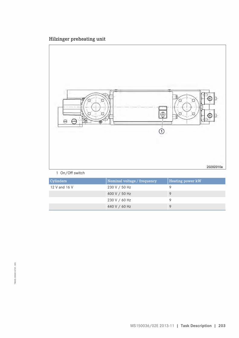
Hilzinger preheating unit
1 On/Off switch
Cylinders Nominal voltage / frequency Heating power kW12 V and 16 V 230 V / 50 Hz 9
400 V / 50 Hz 9230 V / 60 Hz 9440 V / 60 Hz 9
MS150036/02E 2013-11 | Task Description | 203
TIM
-ID: 0
0000
1474
9 - 0
05

Hilzinger preheating unit, side view
1 Flange (supply and return)2 Junction box
3 Non-return flap4 Continuous flow heater
5 Thermostat6 Circulation pump
FunctionThe preheating unit is intended to warm up the engine coolant. The circulation pump (6) ensures thecirculation of the preheated coolant through the engine.
The continuous flow heater (4) comprises a heating element. A non-return flap (3) prevents coolantfrom flowing through the preheating unit when the engine is running.
When the coolant temperature has reached the value of the thermostat setting (5), the thermostat (5)switches off the preheating unit via contactors.
In the event of excessive coolant temperature, the temperature limiter of the thermostat (5) opens thecontrol loop. The preheater is switched off.
The unit must be reset manually after the fault has been rectified.
204 | Task Description | MS150036/02E 2013-11
TIM
-ID: 0
0000
1474
9 - 0
05

7.15 Raw Water Pump with Connections
7.15.1 Raw water pump – Relief bore check
DANGER Rotating and moving engine parts.Risk of crushing, danger of parts of the body being caught or pulled in!• Only run the engine at low power. Keep away from the engine's danger zone.
WARNING High level of engine noise when the engine is running.Risk of damage to hearing!• Wear ear protectors.
Raw water pump – Relief borecheck
1. Check relief bore for oil and coolant dis-charge.
2. Stop engine (→ Page 95) and disable en-gine start.
3. Clean the relief bore with a wire if it isdirty.• Permissible engine coolant discharge:
up to 10 drops per hour;• Permissible oil discharge: up to 5 drops
per hour.4. If discharge exceeds the specified limits,
contact Service.
MS150036/02E 2013-11 | Task Description | 205
TIM
-ID: 0
0000
1517
3 - 0
05

7.16 Battery-Charging Generator
7.16.1 Battery-charging generator drive – Coupling condition check
Preconditions☑ Engine is stopped and starting disabled.
Battery-charging generator drive– Coupling condition check
1. Remove screws (1).2. Remove protective cover (2).3. Check resilient coupling (3) for cracks and
plastic deformation.4. If there is serious deformation or crack for-
mation, contact Service.5. Install protective cover (2) with screws (1).
206 | Task Description | MS150036/02E 2013-11
TIM
-ID: 0
0000
0739
0 - 0
08
7.17 Engine Mounting / Support
7.17.1 Engine mounting – Checking securing screws for firm seating
Preconditions☑ Engine is stopped and starting disabled.
Engine mounting, checking securing screws for firm seating1. Check securing screws for firm seating.2. Tighten loose threaded connections.
MS150036/02E 2013-11 | Task Description | 207
TIM
-ID: 0
0000
0754
8 - 0
08

7.18 Auxiliary PTO
7.18.1 Bilge pump – Relief bore check
DANGER Rotating and moving engine parts.Risk of crushing, danger of parts of the body being caught or pulled in!• Only run the engine at low power. Keep away from the engine's danger zone.
WARNING High level of engine noise when the engine is running.Risk of damage to hearing!• Wear ear protectors.
Bilge pump – Relief bore check1. Check relief bores for oil and water dis-
charge.2. Stop engine (→ Page 95) and disable en-
gine start.3. Clean relief bores with a wire if dirty.
• Permissible water discharge: up to 10drops per hour;
• Permissible oil discharge: up to 5 dropsper hour
4. If discharge exceeds the specified limits:Contact Service.
208 | Task Description | MS150036/02E 2013-11
TIM
-ID: 0
0000
1579
1 - 0
05
7.19 Fuel Supply System
7.19.1 Water drain valve – Check
Water drain valve – Check1. Open water drain valve.2. Check water outlet for obstructions.3. Close water drain valve.
MS150036/02E 2013-11 | Task Description | 209
TIM
-ID: 0
0000
0773
3 - 0
07

7.19.2 Differential pressure gauge – Check
WARNING Fuels are combustible.Risk of fire and explosion!• Avoid open flames, electrical sparks and ignition sources.• Do not smoke.
Checking differential pressure gauge1. Switch on fuel treatment system (→ Page 93).2. Set the alarm points at the differential pressure gauge to zero.
Result: Alarm is initiated with preset delay.3. Reset the alarm points at the differential pressure gauge to the specified values.
210 | Task Description | MS150036/02E 2013-11
TIM
-ID: 0
0000
0773
7 - 0
05

7.19.3 Water level probe (3-in-1 rod electrode) – Check
Preconditions☑ System is put out of operation and emptied.
WARNING Fuels are combustible.Risk of fire and explosion!• Avoid open flames, electrical sparks and ignition sources.• Do not smoke.
Checking water level probe (3-in-1 rod electrode)1. Disconnect connector from water level probe.2. Unscrew water level probe.3. Disconnect connector from water level probe.4. Immerse water level probe into a tank filled with water until water level reaches the thread.5. Switch system on.
Result: Water drain valve opens.6. Leave water level probe in tank.
Result: Alarm must be triggered with the preset delay.7. Switch off the system.8. Disconnect connector from water level probe.9. Remove water level probe from tank.
10. Screw in water level probe.11. Connect connector for water level probe.12. Fill and vent the system then put it into operation.
MS150036/02E 2013-11 | Task Description | 211
TIM
-ID: 0
0000
0773
9 - 0
07

7.19.4 Pump capacity – Check
WARNING Fuels are combustible.Risk of fire and explosion!• Avoid open flames, electrical sparks and ignition sources.• Do not smoke.
Pump capacity – Check1. Install suitable pressure gauge at the neck of the intake side of the pump.2. Check pump pressure.
a) Switch on fuel treatment system (→ Page 93).
Note: The pressure limiting valve at the pump might respond and open. Audible noise is caused by overflow-ing fuel and can be disregarded.
b) Close ball valve at the outlet of the fuel treatment system.c) Check pressure at the pressure gauge in the inlet to the fuel treatment system and note down.
3. Check pump pressure with reduced suction.a) Reduce suction pressure of pump to -0.8 bar with the shutoff valve at the pump intake side.b) Check pressure at the pressure gauge in the inlet to the fuel treatment system and note down.c) Open ball valve at inlet and outlet of fuel treatment system.
4. Calculate wear limit.
Example:Measured value (normal condition). 3 barMeasured value (reduced suction condition). 2.6 barIf the measured value (reduced suction condition) is 10% lower than the measured value (normal condition),the wear limit is reached. Repair pump (contact Service).
212 | Task Description | MS150036/02E 2013-11
TIM
-ID: 0
0000
0774
0 - 0
08

7.19.5 Coalescer filter element – Replacement
Preconditions☑ System is stopped and starting disabled.
Special tools, Material, Spare parts
Designation / Use Part No. Qty.
Torque wrench, 6-50 Nm F30027336 1Ratchet F30027339 1Diesel fuelEngine oilCoalescer filter element (→ Spare Parts Catalog)Gasket (→ Spare Parts Catalog)
WARNING Fuels are combustible.Risk of fire and explosion!• Avoid open flames, electrical sparks and ignition sources.• Do not smoke.
NOTICE Contamination of components.Damage to component!• Observe manufacturer's instructions.• Check components for special cleanliness.
NOTICE Incorrect installation of components and lines.Damage to component!• Ensure that components/lines are installed so that they are never under tension or strain.• Ensure correct installation position of components.
Coalescer filter element – Re-placement
1. Close ball valve at the inlet and outlet ofthe fuel treatment system.
2. Open drain valve.3. Drain fuel.4. Close drain valve.5. Remove nuts (9) and washers (2).6. Remove screws (1).7. Remove cover with gasket (10).8. Remove nut (3), washer (8) and end
plate (4).9. Remove coalescer filter element (5).
10. Catch fuel as it runs out.11. Clean housing with a non-linting cloth,
rinse with fuel if required.12. Check housing for corrosion.13. Clean housing sealing surfaces.14. Install coalescer filter element (5).15. Install end plate (4), washer (8) and nut (3).
MS150036/02E 2013-11 | Task Description | 213
TIM
-ID: 0
0000
0773
5 - 0
09
16. Tighten nut (3) to specified tightening torque using a torque wrench.
Name Size Type Lubricant Value/Standard
Nut M16 Tightening torque (Engine oil) 30 Nm +3 Nm
17. Fit gasket (10).18. Install cover.19. Install screws (1), washers (2) and nuts (9).20. Tighten nuts (9).21. Open ball valve at the inlet and outlet of the fuel treatment system.
Result: The fuel treatment system is ready for operation.
214 | Task Description | MS150036/02E 2013-11
TIM
-ID: 0
0000
0773
5 - 0
09
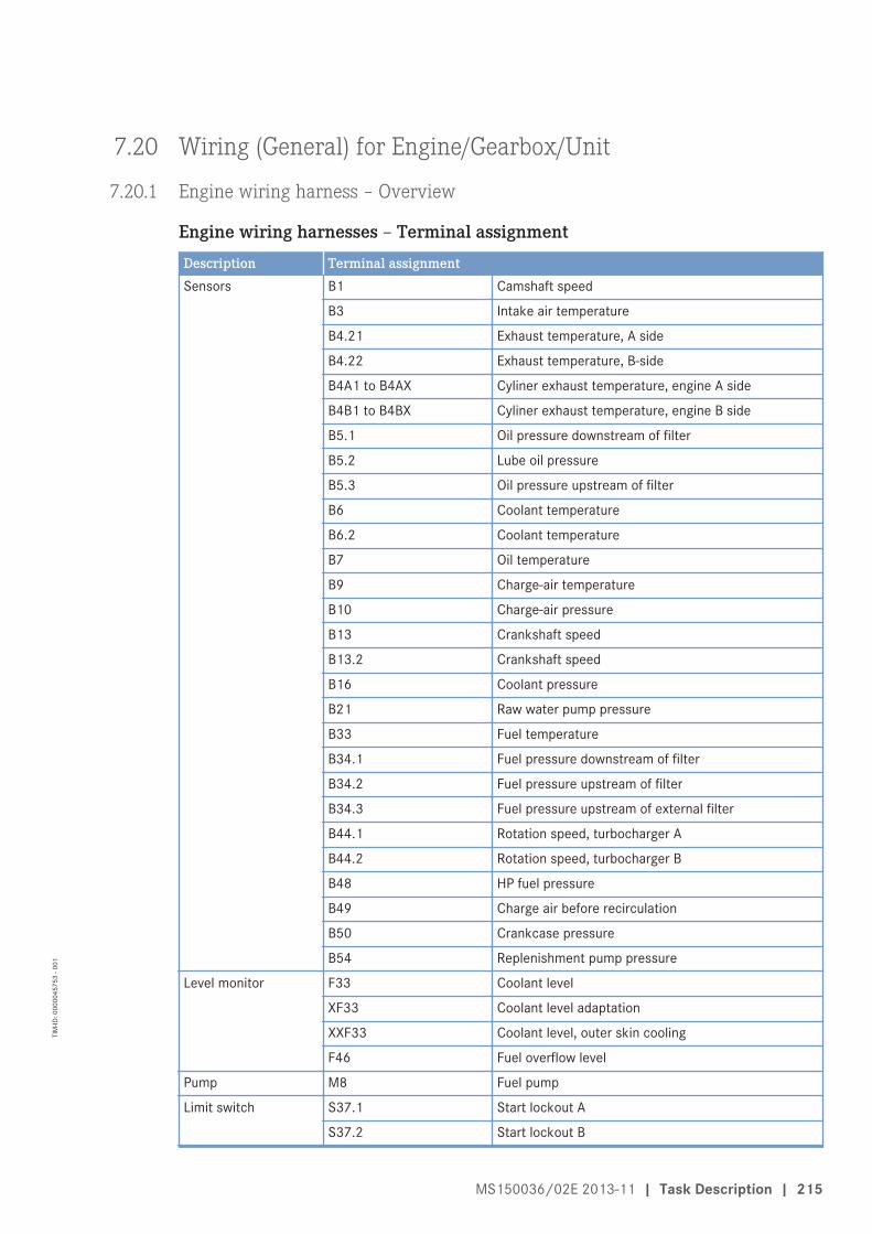
7.20 Wiring (General) for Engine/Gearbox/Unit
7.20.1 Engine wiring harness ‒ Overview
Engine wiring harnesses – Terminal assignmentDescription Terminal assignmentSensors B1 Camshaft speed
B3 Intake air temperature
B4.21 Exhaust temperature, A side
B4.22 Exhaust temperature, B-side
B4A1 to B4AX Cyliner exhaust temperature, engine A side
B4B1 to B4BX Cyliner exhaust temperature, engine B side
B5.1 Oil pressure downstream of filter
B5.2 Lube oil pressure
B5.3 Oil pressure upstream of filter
B6 Coolant temperature
B6.2 Coolant temperature
B7 Oil temperature
B9 Charge-air temperature
B10 Charge-air pressure
B13 Crankshaft speed
B13.2 Crankshaft speed
B16 Coolant pressure
B21 Raw water pump pressure
B33 Fuel temperature
B34.1 Fuel pressure downstream of filter
B34.2 Fuel pressure upstream of filter
B34.3 Fuel pressure upstream of external filter
B44.1 Rotation speed, turbocharger A
B44.2 Rotation speed, turbocharger B
B48 HP fuel pressure
B49 Charge air before recirculation
B50 Crankcase pressure
B54 Replenishment pump pressure
Level monitor F33 Coolant level
XF33 Coolant level adaptation
XXF33 Coolant level, outer skin cooling
F46 Fuel overflow level
Pump M8 Fuel pump
Limit switch S37.1 Start lockout A
S37.2 Start lockout B
MS150036/02E 2013-11 | Task Description | 215
TIM
-ID: 0
0000
4575
3 - 0
01

Description Terminal assignmentAdaptation X1 ECU-7 module
X2 ECU-7 module
X3 ECU power
X4 ECU-7 module
X11 ECU power
X12 EMU
X37 Start interlock
X52 EIM
XB19 Starting-air pressure
XD1 Dialog
XY1 Starting system
XG03 Alternator
Valves Y26 Charge-air recirculation
Y27 Turbocharger
Injectors Y39A1 to Y39AX Engine A side
Y39B1 to Y39BX Engine B side
216 | Task Description | MS150036/02E 2013-11
TIM
-ID: 0
0000
4575
3 - 0
01

Engine wiring harness for sensors, 12V engine
1 M82 B13 B64 X25 X376 XXF337 F338 B169 XF33
10 B5411 B44.212 Y27
13 B4.2214 B915 S37.116 B34.317 B34.218 B34.119 B5020 B4921 B44.122 Y2623 B5.324 B3
25 B4.2126 B1027 B1328 S37.229 B730 B5.131 B4832 B3333 F4634 XG03
MS150036/02E 2013-11 | Task Description | 217
TIM
-ID: 0
0000
4575
3 - 0
01

Engine wiring harness for sensors, 16V engine
1 M82 B13 B64 X25 Y276 B44.27 X378 XF339 B54
10 B1611 XXF3312 F33
13 B4.2214 B915 S37.116 B34.317 B34.218 B34.119 B5020 B4921 B44.122 Y2623 B5.324 B3
25 B4.2126 B1027 B1328 S37.229 B730 B5.131 B4832 B3333 F4634 XG03
218 | Task Description | MS150036/02E 2013-11
TIM
-ID: 0
0000
4575
3 - 0
01
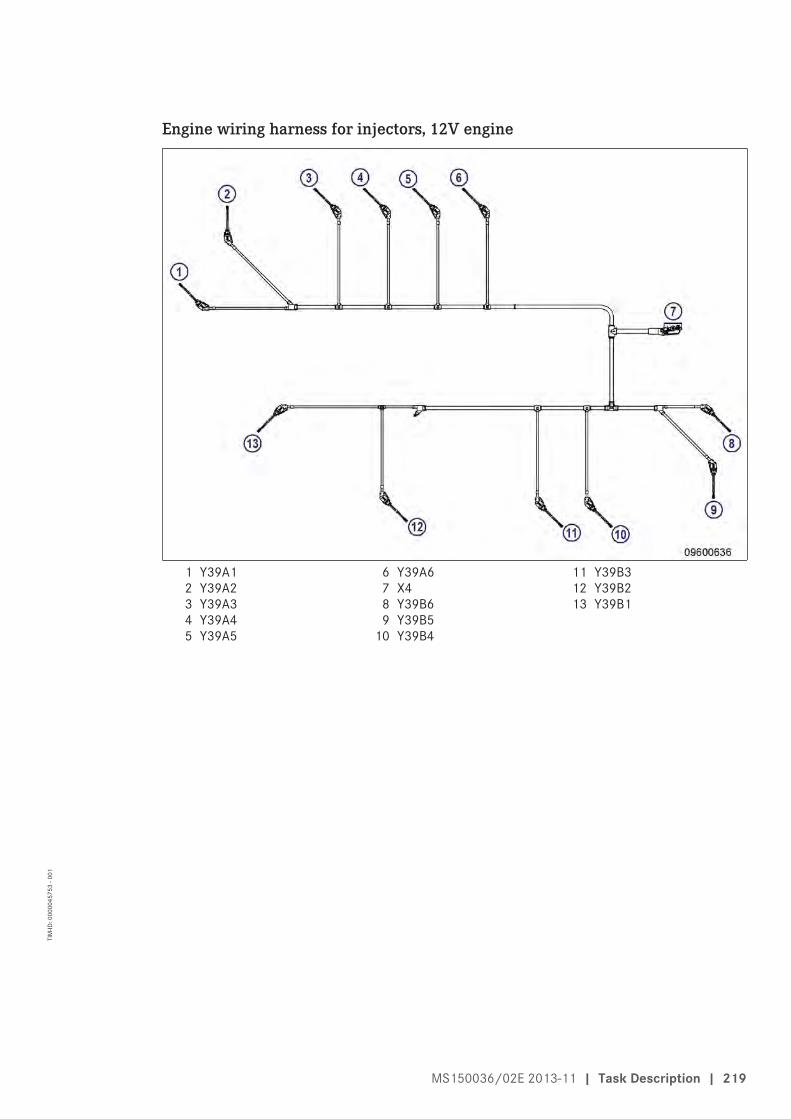
Engine wiring harness for injectors, 12V engine
1 Y39A12 Y39A23 Y39A34 Y39A45 Y39A5
6 Y39A67 X48 Y39B69 Y39B5
10 Y39B4
11 Y39B312 Y39B213 Y39B1
MS150036/02E 2013-11 | Task Description | 219
TIM
-ID: 0
0000
4575
3 - 0
01
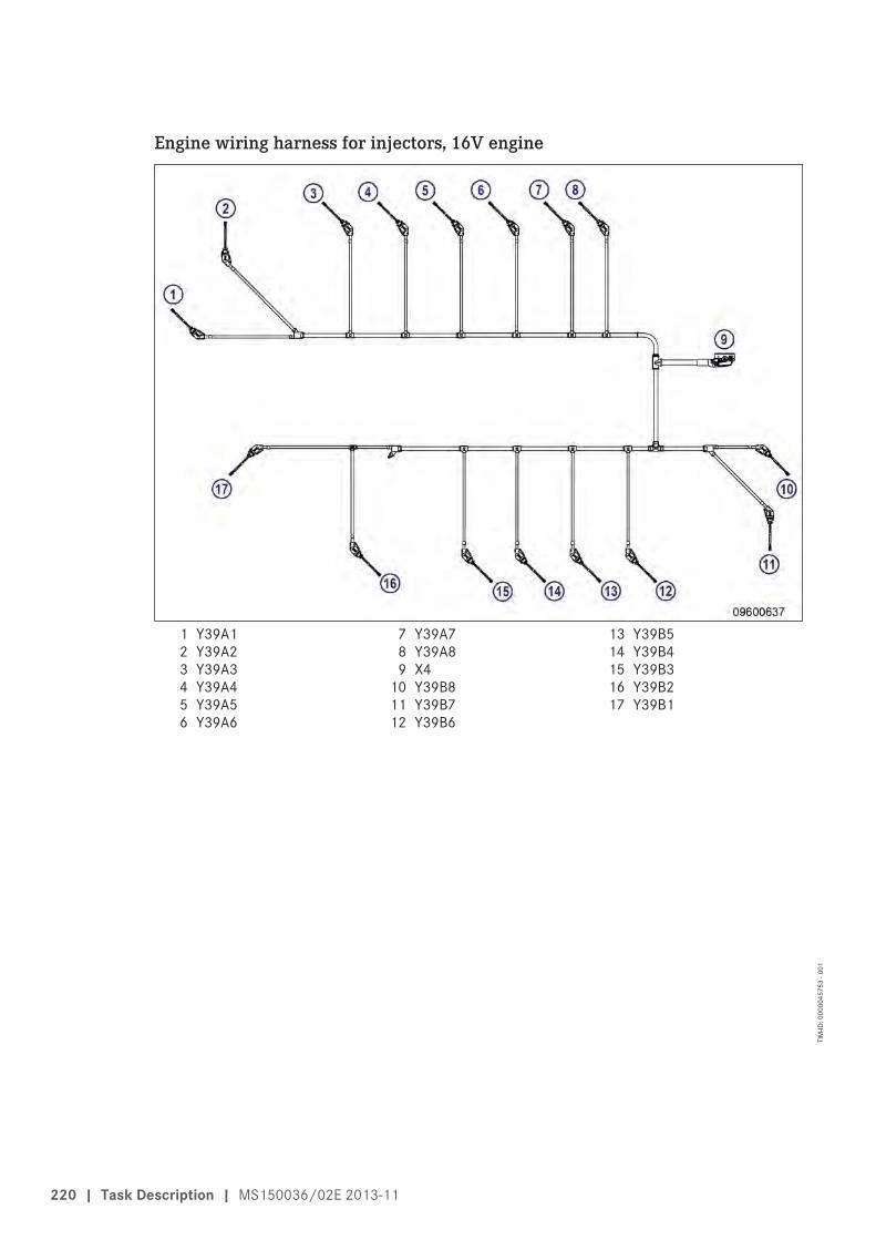
Engine wiring harness for injectors, 16V engine
1 Y39A12 Y39A23 Y39A34 Y39A45 Y39A56 Y39A6
7 Y39A78 Y39A89 X4
10 Y39B811 Y39B712 Y39B6
13 Y39B514 Y39B415 Y39B316 Y39B217 Y39B1
220 | Task Description | MS150036/02E 2013-11
TIM
-ID: 0
0000
4575
3 - 0
01

Wiring harness for engine-mounted sensors, 12V engine
1 B13.22 B4A13 B4A24 B4A35 B4A46 B4A5
7 X128 B6.29 B21
10 B4B611 B4B512 B4B4
13 B4B314 B4B215 B4B116 B5.2
MS150036/02E 2013-11 | Task Description | 221
TIM
-ID: 0
0000
4575
3 - 0
01

Wiring harness for engine-mounted sensors, 16V engine
1 B13.22 B4A13 B4A24 B4A35 B4A46 B4A57 B4A6
8 B4A79 B4A8
10 X1211 B6.212 B2113 B4B814 B4B7
15 B4B616 B4B517 B4B418 B4B319 B4B220 B4B121 B5.2
222 | Task Description | MS150036/02E 2013-11
TIM
-ID: 0
0000
4575
3 - 0
01

Wiring harness for engine interface
1 XD12 X13 X3
4 X525 XY16 X11
7 XB198 X37
MS150036/02E 2013-11 | Task Description | 223
TIM
-ID: 0
0000
4575
3 - 0
01
7.20.2 Engine wiring – Check
Preconditions☑ Engine is stopped and starting disabled.
Special tools, Material, Spare parts
Designation / Use Part No. Qty.
Isopropyl alcohol X00058037 1
Checking engine wiring1. Check securing screws of cable clamps on engine and tighten loose threaded connections.2. Ensure that cables are fixed in their clamps and cannot swing freely.3. Check that cable clamps are firm, tighten loose cable clamps.4. Replace faulty cable clamps.5. Visually inspect the following electrical line components for damage:
• Connector housing• Contacts• Sockets• Cables and terminals• Plug-in contacts
Result: Contact Service if cable conductors are damaged.
Note: Close male connectors that are not plugged in with the protective cap supplied.6. Clean dirty connector housings, sockets and contacts using isopropyl alcohol.7. Ensure that all sensor connectors are securely engaged.
224 | Task Description | MS150036/02E 2013-11
TIM
-ID: 0
0000
0002
9 - 0
19

7.21 Accessories for (Electronic) Engine Governor / Control System
7.21.1 Limit switch for start interlock ‒ Check
Preconditions☑ Engine is stopped and starting disabled.
Note: In the OFF position, the limit switch initiates a start interlock, i.e. the engine cannot be started.Checking limit switch for startinterlock
1. Check whether switches (3) and guardplate (1) with engine support (4) are instal-led on both sides of flywheel housing (2).
2. Check whether both switches (3) are actu-ated.
3. If switches (3) and/or guard plate (1) withengine support (4) is/are not installed:• Screw on guard plate (1) with engine
support (4).• Then screw on switch (3), ensuring that
the switch (3) is actuated by the guardplate (1).
4. If switch (3) and guard plate (1) are instal-led, but switch (3) is in the OFF position:• Make certain that the guard plate (1) at
the side of the switch (3) is not distort-ed.
• Release guard plate (1) and screw onsuch that the switch (3) is actuated.
MS150036/02E 2013-11 | Task Description | 225
TIM
-ID: 0
0000
1678
2 - 0
06

7.21.2 Engine Control Unit ECU 7 – Checking plug connections
Preconditions☑ Engine is stopped and starting disabled.
Check plug connections on ECU7
1. Check all connectors on ECU for firm seat-ing. Ensure that the clips (1) are engaged.
2. Check screws (2) of cable clamps on ECUfor firm seating. Ensure that cable clampsare not faulty.
226 | Task Description | MS150036/02E 2013-11
TIM
-ID: 0
0000
1684
7 - 0
06
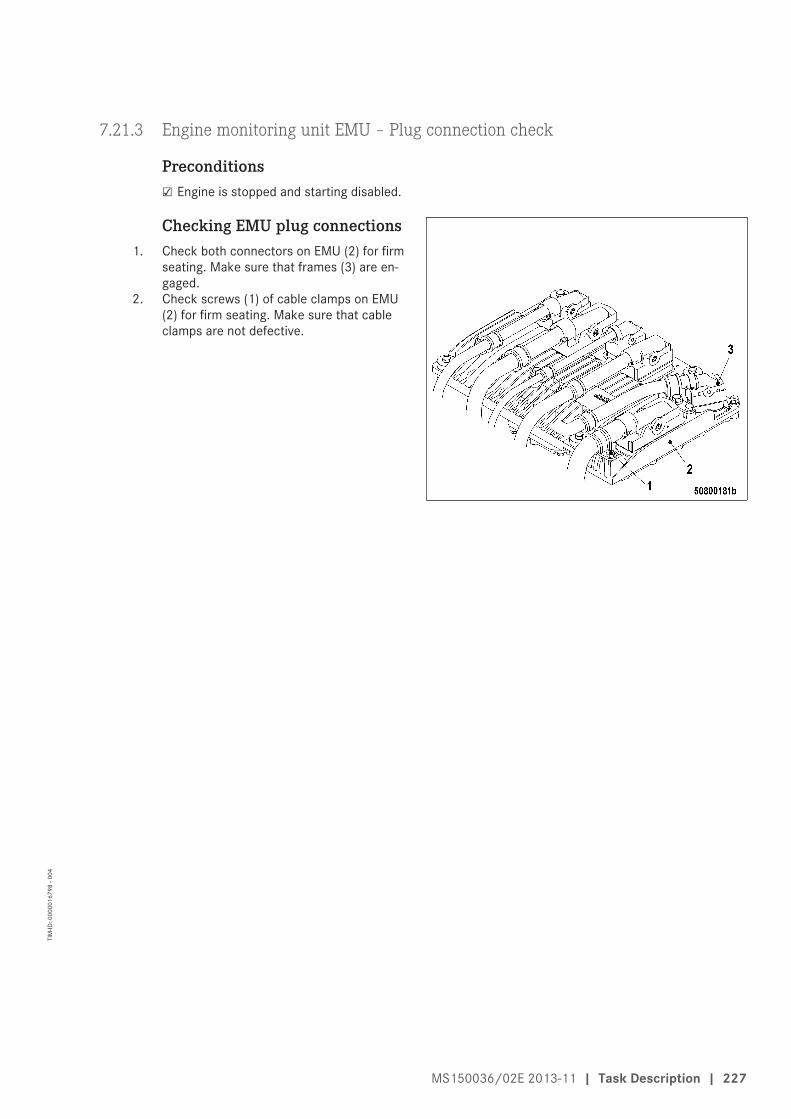
7.21.3 Engine monitoring unit EMU – Plug connection check
Preconditions☑ Engine is stopped and starting disabled.
Checking EMU plug connections1. Check both connectors on EMU (2) for firm
seating. Make sure that frames (3) are en-gaged.
2. Check screws (1) of cable clamps on EMU(2) for firm seating. Make sure that cableclamps are not defective.
MS150036/02E 2013-11 | Task Description | 227
TIM
-ID: 0
0000
1679
8 - 0
04

7.21.4 Interface module EIM plug connections – Check
Preconditions☑ Engine is stopped and starting disabled.
Checking EIM plug connections1. Check both Tyco plugs (62-pole) (2) on EIM
for firm seating. Ensure that clips (3) areengaged.
2. Check screws (1) of cable clamps on EIMfor firm seating. Ensure that cable clampsare not faulty.
228 | Task Description | MS150036/02E 2013-11
TIM
-ID: 0
0000
1703
4 - 0
04

7.21.5 Engine Control Unit ECU 7 – Removal and installation
Preconditions☑ Engine is stopped and starting disabled.
NOTICE Wrong engine governor installed.Engine damage!• When reassembling an engine, make sure that the governor with the data record for the given
engine is installed.
Removing Engine Control Unitfrom engine
1. Note or mark assignment of cables andconnectors.
2. Remove all screws (3).3. Undo clips (2) on connectors.4. Remove all male connectors.5. Remove screws (1).6. Take off Engine Control Unit.
Installing Engine Control Unit on engine1. Install in reverse order. Ensure correct assignment of connectors and sockets.2. Check resilient mount before installing.
Result: If resilient mount is porous or defective then replace it.
MS150036/02E 2013-11 | Task Description | 229
TIM
-ID: 0
0000
0004
9 - 0
08

7.21.6 EMU 7 – Removal and installation
Preconditions☑ Engine is stopped and starting disabled.
NOTICE Wrong engine governor installed.Engine damage!• When reassembling an engine, make sure that the governor with the data record for the given
engine is installed.
Removing ECU with EMU fromengine
1. Note or mark assignment of cables andconnectors.
2. Remove all screws (2).3. Undo latches (3) of the connectors.4. Disconnect all connectors.5. Remove screws (1).6. Remove ECU (5) with EMU (4).
Removing EMU1. Unscrew screws on base of EMU (4).2. Remove EMU (4) from ECU (5).
Installing EMU1. Place EMU (4) on ECU (5).2. Screw in and tighten screws on base of EMU (4).
Installing ECU with EMU on engine1. Install in reverse order. Ensure correct assignment of connectors and sockets in so doing.2. Check resilient mount before installing.
Result: Replace resilient mount if porous or defective.
230 | Task Description | MS150036/02E 2013-11
TIM
-ID: 0
0000
1679
9 - 0
07

7.21.7 Engine Interface Module EIM – Removal and installation
Preconditions☑ Engine is stopped and starting disabled.
Removing EIM from the engine1. Note or mark assignment of cables and
connectors.2. Unscrew all screws (1).3. Undo clips (2) on connectors.4. Disconnect all connectors.5. Unscrew power and starter cable.6. Remove screws (3).7. Take off EIM.
Installing EIM on the engine1. Install in reverse order. When doing so, observe correct assignment between cables and plugs.2. Check seal before installing.
Result: Replace seal if porous or defective.
Downloading software1. The new EIM still does not have appropriate FSW and parameter/descriptor module (the diagnostic
lamp (DILA) indicates flashing code 4 when the power supply is connected, (→ Page 232)).2. The FSW and the parameter/descriptor module must first be downloaded from the central database
(CDB) based on the relevant engine number using the DiaSys software tool, and then loaded in the EIM.
MS150036/02E 2013-11 | Task Description | 231
TIM
-ID: 0
0000
1703
5 - 0
05

7.21.8 Diagnostic features of EIM
Diagnostic lamp (DILA)A diagnostic lamp (LED, blue) is integrated in the housing of the Engine Interface Module (EIM).
It indicates the operating status of the EIM.
Functions of diagnostic lamp DILADILA lights Engine Interface Module (EIM) is OKDILA dark EIM supply voltage missing or diagnostic lamp activation is faulty.DILA flashes Hardware or software fault in the Engine Interface Module.
The diagnostic lamp (DILA) signals the following states:
1 Time in seconds2 Timing: 1/8 s3 Ready for operation
4 Application loader active5 External RAM faulty6 External FLASH faulty
7 No firmware8 Application crashed
Fuse lamp (SILA)A second indicator is the fuse lamp.
This is also integrated in the housing of the Engine Interface Module. It indicates the status of the fuses.
An orange LED is provided to allow diagnosis of a “tripped fuse” fault directly at the unit as it is oftendifficult to pinpoint a fault in the field without cabling diagrams.
This LED is activated by the controller.
Functions of fuse lamp SILASILA dark Norma operating state.SILA flashes orange One or more fuses have tripped.
The fuse lamp (SILA) signals the following states:
232 | Task Description | MS150036/02E 2013-11
TIM
-ID: 0
0000
3800
9 - 0
02

1 Preamble2 ECU current path failed
(S1)3 MCS current path failed
(S2)4 EMU current path failed
(S3)5 Starter voltage: Terminal
30, 31 not connected andPR 10.0600.001 has value1 or 2 (S4)
6 VSP current path failed(S5)
7 SLD current path failed(S6)
8 DDV current path failed(S7)
9 Gear monitoring currentpath failed (S8)
10 Emergency stop currentpath failed – 24V internal(S9)
11 ES pushbutton currentpath failed – 24V external(S10)
12 Key switch current pathfailed (S11)
13 SDAF 1+2 current pathfailed (S12)
14 PIM current path failed(S13)
15 Spare current path failed(S14)
The failed current paths are signaled consecutively following the preamble (LED on for 4 seconds (1)).There is a pause lasting 4 seconds in between.
MS150036/02E 2013-11 | Task Description | 233
TIM
-ID: 0
0000
3800
9 - 0
02

Sample flashing sequences
A Fuse S5 failure (1/2 sec-ond steps)
B Fuse S1 and fuse S4 fail-ure (1/2 second steps)
Note:These bit sequences are transmitted constantly.
Information about the status of the current paths of the EIM is also provided in the CAN message "Sta-tus internal power supply".
234 | Task Description | MS150036/02E 2013-11
TIM
-ID: 0
0000
3800
9 - 0
02

7.21.9 CDC parameters – Reset
Preconditions☑ Engine is stopped and starting disabled.
Note: Failure to reset drift compensation (CDC parameters) will void the emissions certification.
Resetting CDC parameters with DiaSys®u (→ Dialog system DiaSys® E531920/..).
Resetting CDC parameters without DiaSys®u If no DiaSys® is available, contact Service.
MS150036/02E 2013-11 | Task Description | 235
TIM
-ID: 0
0000
4468
4 - 0
01

8 Appendix A
8.1 AbbreviationsAbbrevia-tion
Meaning Explanation
ADEC Advanced Diesel Engine Control Engine governorAL Alarm Alarm (general)ANSI American National Standards Institute Governing body for US American standardsETC Exhaust turbochargerBR Baureihe (Series)BV Betriebsstoffvorschrift Fluids and Lubricants Specifications, MTU Publication
No. A01061/..CAN Controller Area Network Data bus system, bus standardCDC Calibration Drift Compensation Setting for drift correction with DiaSys in engine gov-
ernorCPP Controllable Pitch PropellerDILA Diagnostic lamp on EIMDIN Deutsches Institut für Normung e. V. German Standardization Organization, at the same
time identifier of German standards ("Deutsche In-dustrie-Norm")
DIS Display unit Display panelDL Default Lost Alarm: Default CAN bus failureECS Engine Control System Engine management systemECU Engine Control Unit Engine governorEDM Engine Data Module Memory module for engine dataEIM Engine Interface Module Interface to engine monitoring systemEMU Engine Monitoring UnitSPC Spare Parts CatalogFPP Fixed Pitch PropellerGCU Gear Control UnitGMU Gear Monitoring UnitHAT Harbor Acceptance TestHI High Alarm: Measured value exceeds 1st maximum limitHIHI High High Alarm: Measured value exceeds 2nd maximum limitHT High TemperatureICFN ISO - Continuous rating - Fuel stop
power - NetPower specification in accordance with DIN-ISO3046-7
IDM Interface Data Module Memory module for interface dataIIG Initial Injector Equalization Entering of injector code with DiaSys in engine gover-
norIMO International Maritime OrganizationISO International Organization for Stand-
ardizationInternational umbrella organization for all nationalstandardization institutes
KGS Kraftgegenseite Engine free end in accordance with DIN ISO 1204
236 | Appendix A | MS150036/02E 2013-11
TIM
-ID: 0
0000
0205
0 - 0
05

Abbrevia-tion
Meaning Explanation
KS Kraftseite Engine driving end in accordance with DIN ISO 1204LCD Liquid Crystal Display, Liquid Crystal
DeviceLCU Local Control Unit LOP subassemblyLED Light Emitting DiodeLMU Local Monitoring Unit LOP subassemblyLO Low Alarm: Measured value lower than 1st minimum limitLOLO Low Low Alarm: Measured value lower than 2nd minimum limitLOP Local Operating Panel Control console, control panelLOS Local Operating StationMCS Monitoring and Control SystemMG MessageMPU Microprocessor Unit, Microprocessing
UnitMicroprocessor (unit)
TDC Top Dead CenterP-xyz Pressure-xyz Pressure measuring point xyzPAN Panel Operating panelPCU Propeller Control UnitPIM Peripheral Interface ModuleRCS Remote Control SystemRL Redundancy Lost Alarm: Redundant CAN bus failureSAE Society of Automotive Engineers U.S. standardization organizationSAT Sea Acceptance TestSD Sensor Defect Alarm: Sensor failureSDAF Shut Down Air Flaps Emergency-air shutoff flap(s)SILA Fuse lamp on EIMSOLAS International Convention for the Safety
of Life at SeaSS Safety System Indicated alarm is initiated by the safety systemSSK Emergency-air shutoff flap(s)T-xyz Temperature-xyz Temperature measuring point xyzTD Transmitter Deviation Alarm: Sensor comparison faultBDC Bottom Dead CenterVS Voith Schneider Voith-Schneider driveWJ Water Jet Water jet driveTC Tool CatalogZKP Zugehörigkeit-Kategorie-Parameter Numbering plan for ADEC ECU signals
MS150036/02E 2013-11 | Appendix A | 237
TIM
-ID: 0
0000
0205
0 - 0
05
8.2 MTU contact persons/service partnersOur worldwide sales network with its subsidiaries, sales offices, representatives and customer servicecenters ensures fast and direct support on site and the high availability of our products.
Local supportExperienced and qualified specialists place their knowledge and expertise at your disposal.
For locally available support, go to the MTU Internet site: http://www.mtu-online.com
24h hotlineWith our 24h hotline and the outstanding flexibility of our service staff, we are always ready to assistyou – either during operation, for preventive maintenance, corrective work in case of malfunction orchanged operating conditions, or for spare parts supply.
Your contact person in our Customer Assistance Center:
E-mail: [email protected]
Tel.: +49 7541 9077777
Fax: +49 7541 9077778
Asia/Pacific: +65 6100 2688
North and Latin America: +1 248 560 8000
Spare parts serviceFast, simple and correct identification of spare parts for your drive system or vehicle fleet. The rightspare part at the right time at the right place.
With this aim in mind, we can call on a globally networked spares logistics system, a central warehouseat headquarters and on-site stores at our subsidiary companies, agencies and service workshops.
Your contact at Headquarters:
E-mail: [email protected]
Tel.: +49 7541 908555
Fax: +49 7541 908121
238 | Appendix A | MS150036/02E 2013-11
TIM
-ID: 0
0000
0087
3 - 0
15

9 Appendix B
9.1 Special ToolsBarring device
Part No.: F6555766Qty.:Used in:
1 7.1.1 Engine – Barring manually (→ Page 132)
Feeler gauge
Part No.: Y20010128Qty.:Used in:
1 7.3.2 Valve clearance – Check and adjustment(→ Page 140)
Filter wrench
Part No.: F30379104Qty.:Used in:
1 7.6.2 Additional fuel filter – Replacement (→ Page 153)
Qty.:Used in:
1 7.6.3 Fuel filter – Replacement (→ Page 154)
Qty.:Used in:
7.13.2 Engine oil filter – Replacement (→ Page 183)
Qty.:Used in:
1 7.13.3 Centrifugal oil filter – Cleaning and filter sleevereplacement (→ Page 185)
Qty.:Used in:
1 7.14.8 Engine coolant filter – Replacement(→ Page 201)
MS150036/02E 2013-11 | Appendix B | 239
DCL-
ID: 0
0000
2950
3 - 0
01

Installation/removal tool
Part No.: F6789889Qty.:Used in:
1 7.5.2 Injector – Removal and installation (→ Page 147)
Milling cutter
Part No.: F30452739Qty.:Used in:
1 7.5.2 Injector – Removal and installation (→ Page 147)
MTU test kit
Part No.: 5605892099/00Qty.:Used in:
1 7.12.3 Engine oil – Sample extraction and analysis(→ Page 179)
Qty.:Used in:
1 7.14.7 Engine coolant – Sample extraction and analysis(→ Page 200)
Ratchet
Part No.: F30027340Qty.:Used in:
1 7.5.2 Injector – Removal and installation (→ Page 147)
240 | Appendix B | MS150036/02E 2013-11
DCL-
ID: 0
0000
2950
3 - 0
01
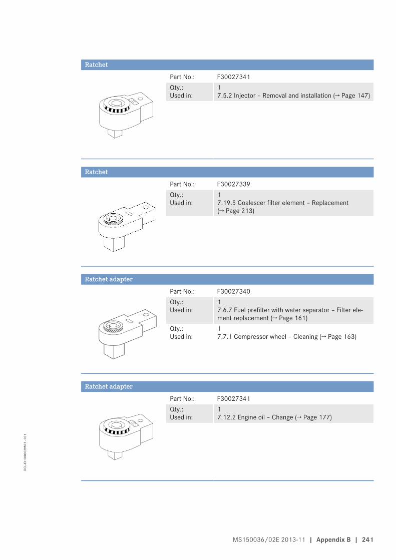
Ratchet
Part No.: F30027341Qty.:Used in:
1 7.5.2 Injector – Removal and installation (→ Page 147)
Ratchet
Part No.: F30027339Qty.:Used in:
1 7.19.5 Coalescer filter element – Replacement(→ Page 213)
Ratchet adapter
Part No.: F30027340Qty.:Used in:
1 7.6.7 Fuel prefilter with water separator – Filter ele-ment replacement (→ Page 161)
Qty.:Used in:
1 7.7.1 Compressor wheel – Cleaning (→ Page 163)
Ratchet adapter
Part No.: F30027341Qty.:Used in:
1 7.12.2 Engine oil – Change (→ Page 177)
MS150036/02E 2013-11 | Appendix B | 241
DCL-
ID: 0
0000
2950
3 - 0
01

Ratchet with extension
Part No.: F30006212Qty.:Used in:
1 7.1.1 Engine – Barring manually (→ Page 132)
Rigid endoscope
Part No.: Y20097353Qty.:Used in:
1 7.2.1 Cylinder liner – Endoscopic examination(→ Page 135)
Socket wrench, 24 mm
Part No.: F30039526Qty.:Used in:
1 7.3.2 Valve clearance – Check and adjustment(→ Page 140)
Steam jet cleaner
Part No.: -Qty.:Used in:
1 4.14 Plant – Cleaning (→ Page 98)
242 | Appendix B | MS150036/02E 2013-11
DCL-
ID: 0
0000
2950
3 - 0
01

Torque wrench, 0.5-5 Nm
Part No.: 0015384230Qty.:Used in:
1 7.5.2 Injector – Removal and installation (→ Page 147)
Torque wrench, 10-60 Nm
Part No.: F30510423Qty.:Used in:
1 7.6.7 Fuel prefilter with water separator – Filter ele-ment replacement (→ Page 161)
Torque wrench, 10-60 Nm
Part No.: F30452769Qty.:Used in:
1 7.7.1 Compressor wheel – Cleaning (→ Page 163)
Torque wrench, 10-60 Nm
Part No.: F30452769Qty.:Used in:
1 7.5.2 Injector – Removal and installation (→ Page 147)
MS150036/02E 2013-11 | Appendix B | 243
DCL-
ID: 0
0000
2950
3 - 0
01

Torque wrench, 40-200 Nm
Part No.: F30027337Qty.:Used in:
1 7.12.2 Engine oil – Change (→ Page 177)
Torque wrench, 6-50 Nm
Part No.: F30027336Qty.:Used in:
1 7.13.3 Centrifugal oil filter – Cleaning and filter sleevereplacement (→ Page 185)
Torque wrench, 6-50 Nm
Part No.: F30027336Qty.:Used in:
1 7.19.5 Coalescer filter element – Replacement(→ Page 213)
Torque wrench, 60-320 Nm
Part No.: F30047446Qty.:Used in:
1 7.3.2 Valve clearance – Check and adjustment(→ Page 140)
244 | Appendix B | MS150036/02E 2013-11
DCL-
ID: 0
0000
2950
3 - 0
01

Torque wrench, 60-320 Nm
Part No.: F30452768Qty.:Used in:
1 7.5.2 Injector – Removal and installation (→ Page 147)
MS150036/02E 2013-11 | Appendix B | 245
DCL-
ID: 0
0000
2950
3 - 0
01

9.2 Index
Preheating unit 202
Numerics
12V 4000 M53R engine data 72
A
Abbreviations 236Actuators – Overview 52Additional fuel filter – Replacement 153ADEC (ECU 7) – Fault messages 105After stopping the engine 97Air filter – Removal and installation 173– Replacement 172
B
Battery-charging generator drive – Coupling condition check 206Bilge pump – Relief bore check 208
C
CDC parameters – Reset 235Centrifugal oil filter – Cleaning 185Charge-air cooler – Checking condensate drain for water discharge and
obstruction 171Checks – Prior to start-up 89Coalescer filter element – Replacement 213Compressor wheel – Cleaning 163Contact persons 238Controls 83Coolant – Change 193Cylinder – Designation 14Cylinder head cover – Removal and installation 143Cylinder liner – Endoscopic examination 135– Instructions and comments on endoscopic and visual
examination 137
D
Designations – Engine sides and cylinders 14Differential pressure gauge – Check 210
Drain and vent points 188Drift compensation – Reset 235
E
ECU 7 – Installation 229– Removal 229EMU 7 – Installation 230– Removal 230Engine – Barring manually 132– Barring with starting system 134– Emergency stop 96– Main dimensions 80– Start 86– Stopping 95– Wiring check 224Engine Control Unit ECU 7 – Checking plug connections 226– Installation 229– Removal 229Engine coolant – Change 193– Draining 194– Filter replacement 201– Sample analysis 200– Sample extraction 200Engine coolant level – Check 192Engine coolant – Filling 197Engine data – 16V 4000 M53R 76Engine governor ADEC (ECU 7) – Fault messages 105Engine Interface Module EIM – Removal and installation 231Engine layout 38Engine monitoring unit EMU 7 – Plug connection check 227Engine mounting – Checking securing screws for firm seating 207Engine oil – Sample extraction and analysis 179Engine oil – Change 177Engine oil filter – Replacement 183Engine oil level – Check 176Engine sides – Designation 14Engine wiring – Check 224
246 | Appendix B | MS150036/02E 2013-11
DCL-
ID: 0
0000
2950
3 - 0
01

Engine wiring harness – Overview 215
F
Fault messages – Engine governor ADEC (ECU 7) 105Filter – Coalescer element
– Replacement 213– Engine coolant
– Replacement 201Filter sleeve – Replacement 185Firing order 82Fuel – Treatment system
– Switching on 93– Troubleshooting 104
– treatment system – Shutdown 94
Fuel filter – Replacement 154Fuel prefilter – Flushing 159Fuel prefilter – Draining 157Fuel prefilter with water separator – Filter element replacement 161Fuel prefilter – Differential pressure gauge – Adjustment 156– Check 156Fuel treatment system – Putting into operation 90– Shutdown 94– Switching on 93
H
Hotline 238HP pump – Filling with engine oil 144– Relief bore check 145HT coolant pump – Relief bore check 199
I
Injector – Installation 147– Removal 147– Replacement 146Interface module EIM – Check 228
L
Limit switch for start interlock – Check 225
M
Maintenance schedule – Maintenance task reference table [QL1] 99
MTU contact persons 238
O
Oil indicator filter – Checking 181Operational checks 87
P
Plant – Cleaning 98Plug connections – Check 228Product description 15Pump capacity – Check 212Putting the engine into operation after extended out-of-
service periods (>3 months) 84Putting the engine into operation after scheduled out-of-
service-period 85
R
Raw water pump – Relief bore check 205
S
Safety notices, standards 13Safety regulations – Consumables 11– Environmental protection 11– Fire prevention 11– Fluids and lubricants 11– Important provisions 5– Maintenance work 8– Organizational requirements 6– Personnel requirements 6– Repair work 8– Safety notices, standards 13Sensors – Overview 52Sensors and actuators – Overview 42Service indicator – Signal ring position check 174Service partners 238Spare parts service 238Starter – Condition check 175Supplementary fuel filter – Overview 152
T
Tasks – After extended out-of-service periods 88Tasks after extended out-of-service periods (>3 weeks) 88transport 7Troubleshooting 101– Fuel treatment system 104
MS150036/02E 2013-11 | Appendix B | 247
DCL-
ID: 0
0000
2950
3 - 0
01

V
Valve clearance – Adjustment 140– Check 140Valve gear – Lubrication 139
W
Water drain valve – Check 209Water level probe (3-in-1 rod electrode) – Check 211
248 | Appendix B | MS150036/02E 2013-11
DCL-
ID: 0
0000
2950
3 - 0
01


