
Operating Instructions Diesel engine - MTU Online · Operating Instructions Diesel engine V 4000...
204
Operating Instructions Diesel engine V 4000 M70 V 4000 M71 Application group 1B M015412/03E
Transcript of Operating Instructions Diesel engine - MTU Online · Operating Instructions Diesel engine V 4000...

Operating InstructionsDiesel engineV 4000 M70V 4000 M71Application group 1B
M015412/03E

Printed in Germany© 2012 Copyright MTU Friedrichshafen GmbHThis Publication is protected by copyright and may not be used in any way whether in whole or in part without the priorwritten permission of MTU Friedrichshafen GmbH. This restriction also applies to copyright, distribution, translation, micro‐filming and storage or processing on electronic systems including data bases and online services.This handbook is provided for use by maintenance and operating personnel in order to avoid malfunctions or damageduring operation.Subject to alterations and amendments.

Table of Contents1 Safety
1.1 General conditions 61.2 Personnel and organizational requirements 71.3 Transport 81.4 Safety regulations for startup and operation 91.5 Explosion hazard when removing
inspection port cover on engine 101.6 Safety regulations for maintenance and
repair work 111.7 Auxiliary materials, fire prevention and
environmental protection 141.8 Conventions for safety instructions in the
text 17
2 General Information
2.1 Engine side and cylinder designations 182.2 Product description 192.3 Engine – Overview 262.4 Engine – Overview 27
3 Technical Data
3.1 8V 4000 M70 engine data: IMO, separateheat exchanger, copper-based alloyintercooler 29
3.2 8V 4000 M70 engine data: engine-mountedheat exchanger, IMO 32
3.3 12V 4000 M70 engine data: IMO -20%,separate heat exchanger, copper-basedalloy intercooler 35
3.4 12V 4000 M70 engine data: IMO -20%,engine-mounted heat exchanger, copper-based alloy intercooler 38
3.5 12V 4000 M70 engine data: engine-mounted heat exchanger, EPA stage 2 41
3.6 12V 4000 M70 engine data: separate heatexchanger, EPA stage 2 44
3.7 16V 4000 M70 engine data: IMO, separateheat exchanger, copper-based alloyintercooler 47
3.8 16V 4000 M70 engine data: IMO, engine-mounted heat exchanger, copper-basedalloy intercooler 50
3.9 16V 4000 M70 engine data: IMO -20%,separate heat exchanger, copper-basedalloy intercooler 53
3.10 16V 4000 M70 engine data: IMO -20%,engine-mounted heat exchanger, copper-based alloy intercooler 56
3.11 16V 4000 M70 engine data: engine-mounted heat exchanger, EPA stage 2 59
3.12 16V 4000 M70 engine data: separate heatexchanger, EPA stage 2 62
3.13 12V 4000 M71 engine data: IMO, separateheat exchanger, copper-based alloyintercooler 65
3.14 12V 4000 M71 engine data: IMO, engine-mounted heat exchanger, copper-basedalloy intercooler 68
3.15 12V 4000 M71 engine data: IMO, separateheat exchanger, copper-based alloyintercooler, intake air temperature 45° 71
3.16 16V 4000 M71 engine data: IMO, separateheat exchanger, copper-based alloyintercooler 74
3.17 16V 4000 M71 engine data: IMO, engine-mounted heat exchanger, copper-basedalloy intercooler 77
3.18 16V 4000 M71 engine data: IMO, separateheat exchanger, copper-based alloyintercooler, intake air temperature 45° 80
3.19 Firing order 833.20 Engine – Main dimensions 84
4 Operation
4.1 LOP – Controls 854.2 Engine – Preparations for putting into
operation after extended out-of-serviceperiods (>3 months) 87
4.3 Putting the engine into operation afterscheduled out-of-service-period 88
4.4 Tasks after extended out-of-service periods(>3 weeks) 89
4.5 Checks prior to start-up 904.6 Fuel treatment system – Putting into
operation 914.7 Starting the engine from LOP 934.8 Starting the engine at the BlueLine
automation system (control stand) 944.9 Fuel treatment system – Switching on 95
4.10 Operational checks 964.11 Clutch – Engaging from LOP 974.12 Clutch – Disengaging from LOP 984.13 Waterjet – Flushing from LOP (optional) 99
M015412/03E 2012-02 | Table of Contents | 3
DCL-
ID: 0
0000
1667
1 - 0
01

4.14 Stopping the engine from LOP 1004.15 Stopping the engine at the BlueLine
automation system (control stand) 1014.16 Emergency stop from LOP 1024.17 Engine emergency stop at BlueLine
automation system (control stand) 1034.18 After stopping the engine 1044.19 Fuel treatment system – Shutdown 1054.20 Plant – Cleaning 106
5 Maintenance
5.1 Maintenance task reference table [QL1] 107
6 Troubleshooting
6.1 Troubleshooting 1086.2 LOP fault messages 111
7 Task Description
7.1 Engine 1127.1.1 Engine – Barring manually 1127.1.2 Engine – Barring with starting system 113
7.2 Cylinder Liner 1147.2.1 Cylinder liner – Endoscopic examination 1147.2.2 Cylinder liner – Instructions and comments on
endoscopic and visual examination 116
7.3 Crankcase Breather 1187.3.1 Crankcase breather – Oil separator check 1187.3.2 Crankcase breather – Oil separator
replacement, diaphragm check andreplacement 119
7.4 Valve Drive 1217.4.1 Valve gear - Lubrication 1217.4.2 Valve clearance – Check and adjustment 1227.4.3 Cylinder head cover – Removal and
installation 127
7.5 Injection Pump / HP Pump 1287.5.1 HP pump – Relief bore check 128
7.6 Injection Valve / Injector 1297.6.1 Injector – Replacement 1297.6.2 Injector – Removal and installation 130
7.7 Fuel System 1357.7.1 Fuel system – Venting and filling 135
7.8 Fuel Filter 1377.8.1 Fuel filter – Replacement 137
7.8.2 Fuel prefilter – Draining 1397.8.3 Fuel prefilter ‒ Flushing 1407.8.4 Fuel prefilter – Differential pressure gauge
check and adjustment 1427.8.5 Fuel prefilter – Filter element replacement 143
7.9 Exhaust Turbocharger 1457.9.1 Compressor wheel – Cleaning 145
7.10 Charge-Air Cooling 1477.10.1 Intercooler – Checking condensate drain line
for coolant discharge and obstruction 147
7.11 Air Filter 1487.11.1 Air filter – Replacement 1487.11.2 Air filter – Removal and installation 149
7.12 Starting Equipment 1507.12.1 Starter – Condition check 1507.12.2 Air starter – Manual operation 151
7.13 Air Intake 1527.13.1 Contamination indicator – Signal ring position
check 1527.13.2 Air flap – Check for ease of movement 1537.13.3 Air pipework from air filter to ETC – Check 154
7.14 Lube Oil System, Lube Oil Circuit 1557.14.1 Engine oil level – Check 1557.14.2 Engine oil – Change 1567.14.3 Engine oil – Sample extraction and analysis 158
7.15 Oil Filtration / Cooling 1597.15.1 Engine oil filter – Replacement 1597.15.2 Centrifugal oil filter – Cleaning and filter
sleeve replacement 161
7.16 Coolant Circuit, General, High-Temperature Circuit 163
7.16.1 Venting points 1637.16.2 Engine coolant – Level check 1647.16.3 Engine coolant – Change 1657.16.4 Engine coolant – Draining 1667.16.5 Engine coolant – Filling 1677.16.6 Engine coolant pump – Relief bore check 1707.16.7 Engine coolant – Sample extraction and
analysis 171
7.17 Raw Water Pump with Connections 1727.17.1 Raw water pump – Relief bore check 172
7.18 Battery-Charging Generator 1737.18.1 Battery-charging generator drive – Coupling
condition check 173
7.19 Engine Mounting / Support 1747.19.1 Engine mounts – Checking securing screws
for firm seating 1747.19.2 Engine mounts – Resilient element check 175
4 | Table of Contents | M015412/03E 2012-02
DCL-
ID: 0
0000
1667
1 - 0
01

7.20 Drive Systems, Driving End and Free End(Coupling) 177
7.20.1 Coupling – Condition check 177
7.21 Auxiliary PTO 1787.21.1 Bilge pump – Relief bore check 178
7.22 Fuel Supply System 1797.22.1 Water drain valve – Check 1797.22.2 Differential pressure gauge – Check 1807.22.3 Water level probe (3-in-1 rod electrode) –
Check 1817.22.4 Pump capacity – Check 1827.22.5 Coalescer filter element – Replacement 183
7.23 Wiring (General) for Engine/Gearbox/Unit 1857.23.1 Engine wiring – Check 185
7.24 Accessories for (Electronic) EngineGovernor / Control System 186
7.24.1 Engine governor and connectors – Cleaning 1867.24.2 Engine monitoring unit and connectors –
Cleaning 187
7.24.3 Limit switch for start interlock ‒ Check 1887.24.4 Checking engine control unit plug connections 1897.24.5 Engine monitoring unit – Plug connection
check 1907.24.6 Engine control unit – Removal and installation 1917.24.7 LOP – Visual inspection 193
8 Appendix A
8. Abbreviations 08. MTU contacts/service partners 0
9 Appendix B
9.1 Special Tools 1989.2 Index 202
M015412/03E 2012-02 | Table of Contents | 5
DCL-
ID: 0
0000
1667
1 - 0
01

1 Safety1.1 General conditions
GeneralIn addition to the instructions in this publication, the applicable country-specific legislation and other com‐pulsory regulations regarding accident prevention and environmental protection must be observed. Thisstate-of-the-art engine has been designed to meet all applicable laws and regulations. The engine maynevertheless present a risk of injury or damage in the following cases:• Incorrect use• Operation, maintenance and repair by unqualified personnel• Modifications or conversions• Noncompliance with the Safety Instructions
Correct useThe engine is intended solely for use in accordance with contractual agreements and the purpose envis‐aged for it on delivery. Any other use is considered improper use. The engine manufacturer accepts noliability whatsoever for resultant damage or injury in such case. The responsibility is borne by the useralone.Correct use also includes observation of and compliance with the maintenance specifications.
Modifications or conversionsUnauthorized modifications to the engine represent a safety risk.MTU will accept no liability or warranty claims for any damage caused by unauthorized modifications orconversions.
Spare partsOnly genuine MTU spare parts must be used to replace components or assemblies. MTU accepts noliability whatsoever for damage or injury resulting from the use of other spare parts and the warranty shallbe voided in such case.
Reworking componentsRepair or engine overhaul must be carried out in workshops authorized by MTU.
6 | Safety | M015412/03E 2012-02
TIM
-ID: 0
0000
0086
0 - 0
17

1.2 Personnel and organizational requirements
Personnel requirementsWork on the engine must only be carried out by appropriately qualified and instructed personnel.Observe the minimum legal age.Responsibilities of the operating, maintenance and repair personnel must be specified by the operatingcompany.
Organizational measuresThis publication must be issued to all personnel involved in operation, maintenance, repair or transporta‐tion.Keep it handy in the vicinity of the engine such that it is accessible to operating, maintenance, repair andtransport personnel at all times.Use the manual as a basis for instructing personnel on engine operation and repair. In particular, person‐nel must have read and understood the safety-relevant instructions.This is especially important for personnel who work on the engine only on an occasional basis. Thesepersons shall receive repeated instruction.Use the Spare Parts Catalog to identify spare parts during maintenance and repair work.
Working clothes and protective equipmentWear proper protective clothing for all work.Depending on the kind of work, use the necessary personal protective equipment.
M015412/03E 2012-02 | Safety | 7
TIM
-ID: 0
0000
0087
4 - 0
17

1.3 Transport
TransportUse only the lifting eyes provided to lift the engine.Only use transport and lifting devices approved by MTU.Take the engine's center of gravity into account.Transport the engine in the installation position only, max. permissible diagonal pull 10°.In the case of special packaging with aluminum foil, suspend the engine by the lifting eyes of the trans‐port pallet or transport with equipment suitable for heavy loads (forklift truck).Install the crankshaft locking device and the locking screws for the engine mounts prior to engine trans‐portation.Secure the engine against tilting during transportation. The engine must be additionally secured againstslipping or tilting when going up or down inclines and ramps.
Setting down the engine following transportationSet the engine down on a firm, level surface only.Make sure that the consistency and load-bearing capacity of the ground or support surface is adequate.Never set an engine down on the oil pan unless expressively authorized to do so by MTU on a case-to-case basis .
8 | Safety | M015412/03E 2012-02
TIM
-ID: 0
0000
0262
2 - 0
06

1.4 Safety regulations for startup and operation
Safety requirements for initial operationPrior to initial operation of the unit, install the assembly or unit according to the specifications and checkthe installation according to the MTU specifications.Before putting the device or plant into operation, always ensure:• that all maintenance and repair work is completed,• that all loose parts have been removed from rotating machine components,• that nobody is in the danger area of moving machine parts.Immediately after putting the device or plant into operation, make sure that all control and display instru‐ments as well as the signaling and alarm systems work properly.
Safety requirements for operatorsThe procedures for cases of emergency must be practiced regularly.The operator must be familiar with the control and display elements.The operator must be familiar with the consequences of any operations performed.During operation, the display instruments and monitoring units must be permanently observed with re‐gard to present operating status, violation of limit values and warning or alarm messages.The following steps must be taken if a malfunction of the system is recognized or reported by the system:• inform supervisor(s) in charge,• analyze the message,• if required, carry out emergency operations e.g. emergency engine stop.
Engine operationThe following conditions must be fulfilled before starting the engine:• Wear ear protection.• Ensure that the engine room is well ventilated.• Do not inhale engine exhaust gases.• Ensure that the exhaust system is free of leaks and that the gases are discharged to atmosphere.• Mop up any leaked or spilt fluids and lubricants immediately or soak up with a suitable binding agent.• Protect battery terminals, battery-charger terminals and cables against accidental contact.• When the engine is running, never release coolant, oil, fuel, compressed-air or hydraulic lines.
Operation of electrical equipmentWhen electrical equipment is in operation, certain components of these appliances are electrically live.Observe the safety instructions for these devices.
M015412/03E 2012-02 | Safety | 9
TIM
-ID: 0
0000
2374
3 - 0
09

1.5 Explosion hazard when removing inspection port cover onengine
DANGER Explosion hazard due to oil vapors.Risk of serious injury – danger to life!• Allow the engine to cool down before opening the crankcase!• Avoid open flames, electrical sparks and ignition sources.
Safety instructionsu Before starting maintenance work, allow the engine to cool down for at least 10 min. (danger of explosion
due to oil vapors).
10 | Safety | M015412/03E 2012-02
TIM
-ID: 0
0000
2293
1 - 0
06

1.6 Safety regulations for maintenance and repair work
Safety regulations for maintenance and repair workHave maintenance and repair work carried out by qualified and authorized personnel only.Allow the engine to cool down before starting maintenance work (risk of explosion of oil vapors).Before starting work, relieve pressure in systems and compressed-air lines which are to be opened.Take special care when removing ventilation or plug screws from the engine. Cover the screw or plugwith a rag to prevent fluids escaping under pressure.Take special care when draining hot fluids ⇒ Risk of injury.When changing the engine oil or working on the fuel system, ensure that the engine room is adequatelyventilated.Allow the engine / system to cool down before starting to work.Observe the maintenance and repair instructions.Never carry out maintenance and repair work with the engine running unless expressly instructed to doso.Secure the engine against accidental starting.Disconnect the battery when electrical starters are fitted.Close the main valve on the compressed-air system and vent the compressed-air line when pneumaticstarters are fitted.Disconnect the control equipment from the assembly or system.Use only proper, calibrated tools. Observe the specified tightening torques during assembly/disassembly.Carry out work only on assembles and/or units which are properly secured.Never use lines for climbing.Keep fuel injection lines and connections clean.Always seal connections with caps or covers if a line is removed or opened.Take care not to damage lines, in particular fuel lines, during maintenance and repair work.Ensure that all retainers and dampers are installed correctly.Ensure that all fuel injection and pressurized oil lines are installed with enough clearance to prevent con‐tact with other components. Do not place fuel or oil lines near hot components.Do not touch elastomeric seals if they have carbonized or resinous appearance unless hands are proper‐ly protected.Note cooling time for components which are heated for installation or removal ⇒ Risk of burning.When working high on the engine, always use suitable ladders and work platforms. Make sure compo‐nents are placed on stable surfaces.Observe special cleanness when conducting maintenance and repair work on the assembly or system.After completion of maintenance and repair work, make sure that no loose objects are in/on the assem‐bly or system.Before barring the engine, make sure that nobody is standing in the danger zone. Check that all guardshave been reinstalled and that all tools and loose parts have been removed after working on the engine.The following additional instructions apply to starters with beryllium copper pinion:• Breathing protection of filter class P2 must be applied during maintenance work to avoid health haz‐
ards caused by the beryllium-containing pinion. Do not blow out the interior of the flywheel housing orthe starter with compressed air. Clean the flywheel housing inside with a class H dust extraction de‐vice as an additional measure.
M015412/03E 2012-02 | Safety | 11
TIM
-ID: 0
0000
0087
9 - 0
23

Welding workNever carry out welding work on the assembly, system, or engine-mounted units. Cover the engine whenwelding in its vicinity.Do not use the assembly or system as ground terminal.Do not route the welding lead over or near the wiring harnesses of MTU systems. The welding currentmay otherwise induce an interference voltage in the wiring harnesses which could conceivably damagethe electrical system.Remove parts (e.g. exhaust pipes) which are to be welded from the engine beforehand.
Hydraulic installation and removalCheck the function and safe operating condition of tools and fixtures to be used. Use only the specifieddevices for hydraulic removal/installation procedures.Observe the max. permissible push-on pressure specified for the equipment.Do not attempt to bend or apply force to lines.Before starting work, pay attention to the following:• Vent the hydraulic installation/removal tool, the pumps and the lines at the relevant points for the
equipment to be used (e.g. open vent plugs, pump until bubble-free air emerges, close vent plugs).• For hydraulic installation, screw on the tool with the piston retracted.• For hydraulic removal, screw on the tool with the piston extended.For a hydraulic installation/removal tool with central expansion pressure supply, screw spindle into shaftend until correct sealing is established.During hydraulic installation and removal, ensure that nobody is standing in the immediate vicinity of thecomponent to be installed/removed.
Working on electrical/electronic assembliesAlways obtain the permission of the person in charge before commencing maintenance and repair workor switching off any part of the electronic system required to do so.De-energize the appropriate areas prior to working on assemblies.Do not damage cabling during removal work. When reinstalling ensure that wiring is not damaged duringoperation by contact with sharp objects, by rubbing against other components or by a hot surface.Do not secure cables on lines carrying fluids.Do not use cable binders to secure cables.Always use connector pliers to tighten connectors.Subject the device or system to a function check on completion of all repair work.Store spare parts properly prior to replacement, i.e. protect them against moisture in particular. Pack de‐fective electronic components and assemblies in a suitable manner when dispatched for repair, i.e. par‐ticularly protected against moisture and impact and wrapped in antistatic foil if necessary.
Working with laser equipmentWhen working with laser equipment, always wear special laser-protection goggles ⇒ Heavily focused ra‐diation.Laser equipment must be fitted with the protective devices necessary for safe operation according totype and application.
12 | Safety | M015412/03E 2012-02
TIM
-ID: 0
0000
0087
9 - 0
23

For conducting light-beam procedures and measurement work, only the following laser devices must beused:• Laser devices of classes 1, 2 or 3A.• Laser devices of class 3B, which have maximum output in the visible wavelength range (400 to 700
nm), a maximum output of 5 mW, and in which the beam axis and surface are designed to preventany risk to the eyes.
M015412/03E 2012-02 | Safety | 13
TIM
-ID: 0
0000
0087
9 - 0
23
1.7 Auxiliary materials, fire prevention and environmentalprotection
Fire preventionRectify any fuel or oil leaks immediately; even splashes of oil or fuel on hot components can cause fires -therefore always keep the engine in a clean condition. Do not leave cloths soaked with fluids and lubri‐cants lying around on the engine. Do not store combustible fluids near the engine.Do not weld pipes and components carrying oil or fuel. Before welding, clean with a non-combustiblefluid.When starting the engine with a foreign power source, connect the ground lead last and remove it first.To avoid sparks in the vicinity of the battery, connect the ground lead from the foreign power source tothe ground lead of the engine or to the ground terminal of the starter.Always keep suitable fire-fighting equipment (fire extinguishers) at hand and familiarize yourself with theiruse.
SOLAS classificationOn engines/plants with SOLAS classification, operational checks must include the following tasks:• Check all covers (fitted in accordance with SOLAS requirements) on lube oil and fuel pipe connections
(>1.8 bar) for damage, replace as necessary. (→ Page 19)
NoiseNoise can lead to an increased risk of accident if acoustic signals, warning shouts or noises indicatingdanger are drowned.At all workplaces with a sound pressure level over 85 dB(A), always wear ear protectors (protective wad‐ding, plugs or capsules).
Environmental protectionModification or removal of mechanical or electronic components or the installation of additional compo‐nents as well as the execution of calibration processes that might affect the emission characteristics ofthe engine are prohibited by emission regulations. Emission control units/systems may only be main‐tained, exchanged or repaired if the components used for this purpose are approved by MTU or equiva‐lent components. Noncompliance with these guidelines might represent a violation of the Clean Air Actand could involve the termination of the operating license by the emission authorities. MTU does not ac‐cept any liability for violations of the emission regulations. MTU will provide assistance and advice ifemission-relevant components are intended to be modified. The MTU Maintenance Schedules ensurethe reliability and performance of MTU engines and must be complied with over the entire life cycle of theengine.Only fuels of the specified quality required to achieve emission limits must be used.In Germany, the VAwS (=regulations governing the use of plants that may affect water quality) is applica‐ble, which means work must only be carried out by authorized specialist companies (MTU is an author‐ized specialist company).Dispose of used fluids, lubricants and filters in accordance with local regulations.
Auxiliary materialsUse only fluids and lubricants that have been tested and approved by MTU.Fluids and lubricants must be kept in suitable, properly designated containers. When using fluids, lubri‐cants and other chemical substances, follow the safety instructions applicable to the product. Take carewhen handling hot, chilled or caustic materials. When using inflammable materials, avoid sparks and donot smoke.
14 | Safety | M015412/03E 2012-02
TIM
-ID: 0
0000
0282
8 - 0
04

Lead• When working with lead or lead-containing pastes, avoid direct contact with the skin and do not inhale
lead vapors.• Adopt suitable measures to avoid the formation of lead dust!• Switch on fume extraction system.• After coming into contact with lead or lead-containing materials, wash hands!
Acids and alkaline solutions• When working with acids and alkalis, wear protective goggles or face mask, gloves and protective
clothing.• Immediately remove clothing wetted by acids and alkalis!• Rinse injuries with plenty of water!• Rinse eyes immediately with eyedrops or clean tap water.
Painting• When painting in other than spray booths equipped with extractors, ensure good ventilation. Make
sure that adjacent work areas are not affected.• No naked flames!• No smoking.• Observe fire prevention regulations!• It is absolutely necessary to wear masks providing protection against paint and solvent fumes.
Liquid nitrogen• Store liquid nitrogen only in small quantities and always in regulation containers without fixed covers.• Do not bring liquid nitrogen in contact with the body (eyes, hands), as this causes frostbite and numb‐
ing.• Wear protective clothing, gloves, closed shoes and protective goggles!• Ensure the room is well ventilated. 88% contamination of breathing air with nitrogen will result in suffo‐
cation.• Avoid all knocks and jars to the containers, fixtures or workpieces.
Compressed airCompressed air is air compressed at excess pressure and is stored in tanks from which it can be extract‐ed.The pressure at which the air is kept can be read off at pressure gauges which must be connected to thecompressed air tanks and the compressed air lines.When working with compressed air, safety precautions must be constantly observed:• Pay special attention to the pressure level in the compressed air network and pressure vessel!• Connecting devices and equipment must either be designed for this pressure or, if the permitted pres‐
sure for the connecting elements is lower than the pressure required, a pressure reducing valve andsafety valve (set to permitted pressure) must form an intermediate connection. Hose coupling andconnections must be securely attached!
• Always wear protective goggles when blowing off tools or extracting chips!• The snout of the air nozzle is provided with a protective disc (e.g. rubber disc), which prevents air-
borne particles being reflected and thereby prevents injury to eyes.• First shut off compressed air lines before compressed air equipment is disconnected from the supply
line or before equipment or tool is to be replaced!• Unauthorized use of compressed air, e.g. forcing flammable liquids (danger class AI, AII and B) out of
containers, results in a risk of explosion!• Forcing compressed air into thin-walled containers (e.g. sheet metal, plastic, glass) for drying purpos‐
es or to check for leaks will result in a risk of bursting!• Do not blow dirty clothing with compressed air when being worn on the body.
M015412/03E 2012-02 | Safety | 15
TIM
-ID: 0
0000
0282
8 - 0
04

Used oilUsed oil may contain health-threatening combustion residues.Rub barrier cream into hands! Wash hands after contact with used oil.
16 | Safety | M015412/03E 2012-02
TIM
-ID: 0
0000
0282
8 - 0
04

1.8 Conventions for safety instructions in the text
DANGER In the event of immediate danger.Consequences: Death or serious injury• Remedial action
WARNING In the event of potentially dangerous situations.Consequences: Death or serious injury• Remedial action
CAUTION In the event of dangerous situations.Consequences: Minor injury or material damage• Remedial action
NOTICE In the event of a situation involving potentially adverse effects on the product.Consequences: Material damage.• Remedial action• Additional product information
Note: This manual contains highlighted safety warnings in accordance with the US ANSI Z535 standard whichbegin with one of the signal words listed above depending on the severity of the hazard.
Safety instructions1. Read and familiarize yourself with all safety notices before starting up or repairing the product.2. Pass on all safety instructions to your operating, maintenance, repair and transport personnel.
M015412/03E 2012-02 | Safety | 17
TIM
-ID: 0
0000
0088
1 - 0
17

2 General Information2.1 Engine side and cylinder designations
Engine sides are always designated as viewed from the driving end (KS).The cylinders of the left engine side are designated "A" and those of the right side "B" (as per DIN ISO1204). The cylinders of each bank are numbered consecutively, starting with No. 1 at the driving end ofthe engine.Other components are numbered in the same way, i.e. starting with No. 1 on driving end.
1 KGS = Free end2 Right engine side
3 KS = Driving end4 Left engine side
18 | General Information | M015412/03E 2012-02
TIM
-ID: 0
0000
0086
3 - 0
17

2.2 Product description
Description of the engine
EngineThe engine is a liquid-cooled four-stroke diesel engine, rotating counterclockwise (seen from drivingend), with direct injection, sequential turbocharging and charge air cooling.The engine is monitored by an engine control and monitoring system (MDEC).Monitoring in the engine room is carried out by the local operating panel (LOP).
Fuel systemElectronically controlled common rail injection system with high-pressure pump, pressure accumulator(rail) and single injectors.The electronic control unit controls• Injection start• Injection quantity• Injection pressure
Exhaust systemThe exhaust system is equipped with triple-walled, water-cooled exhaust lines.The triple-walled design permits• low surface temperature,• reduced amount of heat to be dissipated by the coolant,• absolute gas-tightness.
TurbochargingSequential turbocharging with internal, engine-coolant-controlled charge-air cooling. The right-hand ex‐haust turbocharger is cut in and cut out with electronically controlled, hydraulically actuated flaps.
Cooling systemEngine cooling as split-circuit cooling system with plate-core heat exchanger.Heating of the charge air in idle and low-load operation prevents white smoke formation.Seawater only circulates in the engine coolant cooler and seawater pump.
Service blockThe service components are mounted at the auxiliary PTO end.The layout permits easy access for maintenance.Service components:• Raw water pump, coolant pump• Fuel duplex filter, switchable• Lube oil multiple filter, switchable• Centrifugal lube oil filter• Coolant expansion tank
Electronic systemElectronic control and monitoring system with integrated security and test system with interfaces to re‐mote control system (RCS) and to remote control system (MCS).
M015412/03E 2012-02 | General Information | 19
TIM
-ID: 0
0000
0217
9 - 0
02

Electronic engine control unit (ECU)Functions:• Engine speed control with fuel and speed limitation dependent on engine status and operating condi‐
tions;• Control of sequential turbocharging;• Data processing logistics for analog and binary signals;• Interface for data transfer to CAN field bus for remote control and ship-side monitoring;• RS 232 interface for connection of MTU dialog unit.
Electronic Engine Monitoring Unit (EMU), optionalFunctions:• Data processing logistics for analog and binary signals;• Interface for data transfer to CAN field bus for remote control and ship-side monitoring;
Electronic Gear Control Unit (GCU), ship-side wall mountingFunctions:• Data processing logistics for gear coupling control;• Input/output signals as well as data transfer to CAN field bus for remote control and ship-side monitor‐
ing.
Monitoring in engine roomLocal operating panel (LOP)Functions:• Alphanumeric, monochrome LCD display for monitoring of measured values as well as alarms when
limits are violated;• Pushbuttons for menu control and dimming unit;• Combined control and display elements for local engine/gear control;• Flashing light and horn for combined alarm in engine room;• Interface to CAN field bus for connected, communicating monitoring system components.
20 | General Information | M015412/03E 2012-02
TIM
-ID: 0
0000
0217
9 - 0
02

SOLAS – Fire protection specifications
Fuel system, fuel lines with fuel pressure >1.8 bar
1 Return line2 Fuel line on fuel delivery
pump
3 Check valve4 Sealing cone
5 Fuel line on HP fuelpump
6 Fuel line on vent lineAll lines with SOLAS-compliant covers for pipe connections, according to MTU standard MTN5233, areshown.
M015412/03E 2012-02 | General Information | 21
TIM
-ID: 0
0000
0217
9 - 0
02

Lube oil system, oil lines with oil pressure >1.8 bar
1 Seal, oil line to ETC2 Oil line, ETC3 Connection, oil line to dis‐
tributor4 Oil line, ETC5 Oil line, lube oil pump
6 Oil line on distributor7 Connection, oil line on
control block8 Oil line on control block9 Oil lines on T-piece
10 Oil line, valve housing
11 Oil line, actuating cylinderto control block
12 Oil line, actuating cylinderto control block
13 Connection, oil line to ac‐tuating cylinder
All lines with SOLAS-compliant covers for pipe connections, according to MTU standard MTN5233, areshown.
22 | General Information | M015412/03E 2012-02
TIM
-ID: 0
0000
0217
9 - 0
02

Special connections
In case of leakage, the following connection types are spray-protected even without a cover and havebeen confirmed compliant with SOLAS by GL and DNV.
Plug-in pipe connectionThe sleeve (4) covers the joint to prevent lateral spray.Only leak-off along the line is possible, the pressure is decreased significantly if an O-ring (3) defect oc‐curs.The connection is confirmed as compliant with SOLAS by DNV and GL.
Plugs and sensorsScrew-in plugs (2) are sealed toward the outside either with a copper sealing ring (1), according to DIN,or an O-ring (ISO).In case of a loose thread or a defective sealing ring (2), the fluid first has to pass the thread.The pressure is so greatly reduced by this and the faulty sealing ring (2) that any leakage is not underpressure.
M015412/03E 2012-02 | General Information | 23
TIM
-ID: 0
0000
0217
9 - 0
02

HP connections
1 Jacket pipe2 HP line3 O-ring4 Union nut5 Recess for O-ring6 Thrust ring7 Leakage overflow bore
8 Thrust ring9 Union nut
10 Union nut11 Connecting piece12 Snap ring13 Thrust ring14 Compensating washers
15 Union nut16 Thrust ring17 External pipe of HP line18 Internal pipe of HP line19 Ball-type seal area20 Leak fuel connection
The HP fuel line is sealed by the thrust ring (8).If leakage in the area of the thrust ring (8) or the HP line (5) occurs, the emerging fuel is routed to theleakage chamber.The leak fuel is drained off without pressure via the leakage overflow bore (7). The leakage chamber issealed toward the outside by the O-rings (3).This prevents leaking fuel from escaping.The connection is confirmed as compliant with SOLAS by DNV and GL.
24 | General Information | M015412/03E 2012-02
TIM
-ID: 0
0000
0217
9 - 0
02
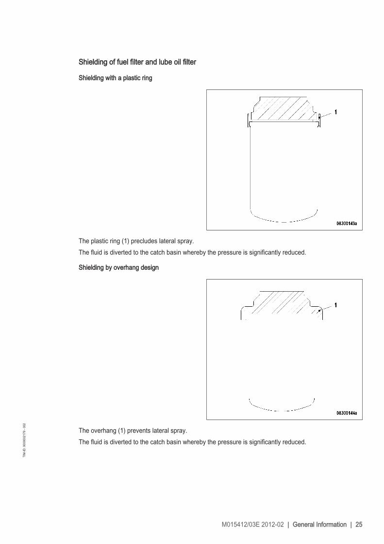
Shielding of fuel filter and lube oil filter
Shielding with a plastic ring
The plastic ring (1) precludes lateral spray.The fluid is diverted to the catch basin whereby the pressure is significantly reduced.
Shielding by overhang design
The overhang (1) prevents lateral spray.The fluid is diverted to the catch basin whereby the pressure is significantly reduced.
M015412/03E 2012-02 | General Information | 25
TIM
-ID: 0
0000
0217
9 - 0
02

2.3 Engine – Overview
1 Exhaust pipework2 Air recirculation valve3 Exhaust turbocharger4 Air intake/air supply5 Oil separator6 Intake elbow7 Exhaust pipework8 Oil heat exchanger9 Coolant expansion tank
10 Engine governor11 Seawater cooler12 Thermostat housing13 Coolant line14 Valve gear
15 Fuel system (high pres‐sure)
16 Fuel system (low pres‐sure)
17 Inspection port cover18 Crankcase19 Running gear20 Valve gear21 Electric power supply, en‐
gine-related*22 Drive systems, driving
end and free end (cou‐pling)*
23 Equipment carrier
24 Engine coolant pump25 Charge-air line26 Mounting/support27 Starting equipment28 Flywheel housing29 Running gear30 Drive systems, driving
end and free end (cou‐pling)*
31 Cylinder head32 Intercooler33 Auxiliary systems / ac‐
cessory equipment** not shown
Engine model designationKey to the engine model designation 8 4000 Mxyz8 Number of cylindersV Cylinder arrangement: V engine4000 SeriesM Applicationx Application segment (4, 5, 6, 7, 9)y Design index (0,1, 2,...)z Additional features
26 | General Information | M015412/03E 2012-02
TIM
-ID: 0
0000
0208
3 - 0
03

2.4 Engine – Overview
010 Crankcase and add-oncomponents
020 Gear train030 Running gear040 Cylinder head050 Valve gear070 Fuel system (high pres‐
sure)080 Fuel system (low pres‐
sure)
100 Exhaust turbocharger110 Intercooler120 Air intake/air supply140 Exhaust pipework170 Starting equipment180 Lube oil system/lube oil
circuit200 Coolant system210 Power supply230 Mounting/support
250 PTO systems, driving endand free end
360 Auxiliary systems and ad‐ditional equipment (not il‐lustrated)
500 Monitoring and controlsystem, general electricdevices
Applies in the same way also to 12 V 4000 M
Engine model designationKey to the engine model designation 16V 4000 Mxyz16 Number of cylindersV Cylinder arrangement: V engine4000 SeriesM Applicationx Application segment (6, 7, 9)
M015412/03E 2012-02 | General Information | 27
TIM
-ID: 0
0000
3624
5 - 0
01

Key to the engine model designation 16V 4000 Mxyzy Design index (0, 1)z R (reduced power / speed)
L (enhanced power / speed)
28 | General Information | M015412/03E 2012-02
TIM
-ID: 0
0000
3624
5 - 0
01

3 Technical Data3.1 8V 4000 M70 engine data: IMO, separate heat exchanger,
copper-based alloy intercooler
Explanation:DL Ref. value: Continuous powerBL Ref. value: Fuel stop power
A Design valueG Guaranteed valueR Guideline valueL Limit value, up to which the engine can be operated without changes (e.g. of power setting)N Not yet defined value- Not applicable
X Applicable
REFERENCE CONDITIONSEngine model 8V 4000
M70Application group 1BIntake air temperature °C 25Raw water inlet temperature °C 25Barometric pressure mbar 1000Site altitude above sea level m 100
POWER-RELATED DATA (power ratings are net brake power to ISO 3046)Number of cylinders 8Engine rated speed A rpm 2000Fuel stop power ISO 3046 A kW 1160
GENERAL CONDITIONS (for maximum power)Number of cylinders 8Intake air depression (new filter) A mbar 25Intake air depression, max. L mbar 35
MODEL-RELATED DATA (basic design)Number of cylinders 8Cylinder configuration: V angle degree 90Bore mm 165Stroke mm 190Cylinder displacement liter 4.06Total displacement liter 32.5
M015412/03E 2012-02 | Technical Data | 29
TIM
-ID: 0
0000
1101
2 - 0
01

Number of cylinders 8Number of inlet valves per cylinder 2Number of exhaust valves per cylinder 2
LUBE OIL SYSTEMNumber of cylinders 8Lube-oil operating temperature before engine, from R °C 85Lube oil temperature before engine, to R °C 90Lube oil operating pressure before engine, from R bar 5.5Lube oil operating pressure before engine, to R bar 6.0Lube oil operating pressure (low idle) (meas. point: before engine) R bar 2.0
FUEL SYSTEMNumber of cylinders 8Fuel pressure at engine supply connection, min. (when engine is starting) L bar -0.1Fuel pressure at supply connection to engine (when engine is running),min.
L bar -0.3
Fuel pressure at engine supply connection, max. (when engine is starting) L bar 1.5Fuel supply flow, max. R liter/min 15.5
GENERAL OPERATING DATANumber of cylinders 8Firing speed, from R rpm 80Firing speed, to R rpm 120
STARTING (electric)Number of cylinders 8Starter, rated voltage (standard design) R V= 24
STARTING (with pneumatic / hydraulic starter)Number of cylinders 8Starting air pressure before starter motor, min. R bar 16Starting air pressure before starter motor, max. R bar 30
INCLINATIONS, STANDARD OIL SYSTEM (reference: waterline)Number of cylinders 8Longitudinal inclination, continuous max. driving end down (Option: max.operating inclinations)
L degree 15
Longitudinal inclination, temporary max. driving end down (Option: max. op‐erating inclinations)
L degree 22.5
Longitudinal inclination, continuous max. driving end up (Option: max. oper‐ating inclinations)
L degree 10
Transverse inclination, continuous max. (Option: max. operating inclina‐tions)
L degree 22.5
30 | Technical Data | M015412/03E 2012-02
TIM
-ID: 0
0000
1101
2 - 0
01

CAPACITIESNumber of cylinders 8Engine oil at initial filling (standard oil system) (Option: max. operating incli‐nations)
R liter 145
Oil change quantity, max. (standard oil system) (Option: max. operating in‐clinations)
R liter 120
Oil pan capacity, dipstick mark min. (standard oil system) (Option: max. op‐erating inclinations)
L liter 110
Oil pan capacity, dipstick mark max. (standard oil system) (Option: max. op‐erating inclinations)
L liter 140
WEIGHTS / MAIN DIMENSIONSNumber of cylinders 8Engine dry weight (with attached standard accessories, without coupling) R kg 4470
ACOUSTICSNumber of cylinders 8Exhaust noise, unsilenced, BL, (free-field sound-pressure level Lp, 1m dis‐tance, ISO 6798)
R db(A) 110
Engine surface noise with attenuated intake noise (filter) - BL (free-fieldsound pressure level Lp, 1m distance, ISO 6798)
R db(A) 109
M015412/03E 2012-02 | Technical Data | 31
TIM
-ID: 0
0000
1101
2 - 0
01

3.2 8V 4000 M70 engine data: engine-mounted heat exchanger,IMO
Explanation:DL Ref. value: Continuous powerBL Ref. value: Fuel stop power
A Design valueG Guaranteed valueR Guideline valueL Limit value, up to which the engine can be operated without changes (e.g. of power setting)N Not yet defined value- Not applicable
X Applicable
REFERENCE CONDITIONSEngine model 8V 4000
M70Application group 1BIntake air temperature °C 25Raw water inlet temperature °C 25Barometric pressure mbar 1000Site altitude above sea level m 100
POWER-RELATED DATA (power ratings are net brake power to ISO 3046)Number of cylinders 8Engine rated speed A rpm 2000Fuel stop power ISO 3046 A kW 1160
GENERAL CONDITIONS (for maximum power)Number of cylinders 8Intake air depression (new filter) A mbar 25Intake air depression, max. L mbar 35
MODEL-RELATED DATA (basic design)Number of cylinders 8Cylinder configuration: V angle degree 90Bore mm 165Stroke mm 190Cylinder displacement liter 4.06Total displacement liter 32.5Number of inlet valves per cylinder 2Number of exhaust valves per cylinder 2
32 | Technical Data | M015412/03E 2012-02
TIM
-ID: 0
0000
1101
7 - 0
01

RAW-WATER CIRCUIT (open circuit)Number of cylinders 8Raw water pump: Inlet pressure, min. L bar -0.2Raw water pump: Inlet pressure , max. L bar 0.5Pressure loss in the external raw-water system, max. L bar 2.2
LUBE OIL SYSTEMNumber of cylinders 8Lube-oil operating temperature before engine, from R °C 85Lube oil temperature before engine, to R °C 90Lube oil operating pressure before engine, from R bar 5.5Lube oil operating pressure before engine, to R bar 6.0Lube oil operating pressure (low idle) (meas. point: before engine) R bar 2.0
FUEL SYSTEMNumber of cylinders 8Fuel pressure at engine supply connection, min. (when engine is starting) L bar -0.1Fuel pressure at supply connection to engine (when engine is running),min.
L bar -0.3
Fuel pressure at engine supply connection, max. (when engine is starting) L bar 1.5Fuel supply flow, max. R liter/min 15.5
GENERAL OPERATING DATANumber of cylinders 8Firing speed, from R rpm 80Firing speed, to R rpm 120
STARTING (electric)Number of cylinders 8Starter, rated voltage (standard design) R V= 24
STARTING (with pneumatic / hydraulic starter)Number of cylinders 8Starting air pressure before starter motor, min. R bar 16Starting air pressure before starter motor, max. R bar 30
M015412/03E 2012-02 | Technical Data | 33
TIM
-ID: 0
0000
1101
7 - 0
01

INCLINATIONS, STANDARD OIL SYSTEM (reference: waterline)Number of cylinders 8Longitudinal inclination, continuous max. driving end down (Option: max.operating inclinations)
L degree 15
Longitudinal inclination, temporary max. driving end down (Option: max. op‐erating inclinations)
L degree 22.5
Longitudinal inclination, continuous max. driving end up (Option: max. oper‐ating inclinations)
L degree 10
Transverse inclination, continuous max. (Option: max. operating inclina‐tions)
L degree 22.5
Transverse inclination, temporary max. (Option: max. operating inclinations) L degree
CAPACITIESNumber of cylinders 8Engine coolant, engine-side (with cooler) R liter 210Engine oil at initial filling (standard oil system) (Option: max. operating incli‐nations)
R liter 145
Oil change quantity, max. (standard oil system) (Option: max. operating in‐clinations)
R liter 120
Oil pan capacity, dipstick mark min. (standard oil system) (Option: max. op‐erating inclinations)
L liter 110
Oil pan capacity, dipstick mark max. (standard oil system) (Option: max. op‐erating inclinations)
L liter 140
WEIGHTS / MAIN DIMENSIONSNumber of cylinders 8Engine dry weight (with attached standard accessories, without coupling) R kg 4670
ACOUSTICSNumber of cylinders 8Exhaust noise, unsilenced, BL, (free-field sound-pressure level Lp, 1m dis‐tance, ISO 6798)
R db(A) 110
Engine surface noise with attenuated intake noise (filter) - BL (free-fieldsound pressure level Lp, 1m distance, ISO 6798)
R db(A) 109
34 | Technical Data | M015412/03E 2012-02
TIM
-ID: 0
0000
1101
7 - 0
01

3.3 12V 4000 M70 engine data: IMO -20%, separate heatexchanger, copper-based alloy intercooler
Explanation:DL Ref. value: Continuous powerBL Ref. value: Fuel stop power
A Design valueG Guaranteed valueR Guideline valueL Limit value, up to which the engine can be operated without changes (e.g. of power setting)N Not yet defined value- Not applicable
X Applicable
REFERENCE CONDITIONSEngine model 12V 4000
M70Application group 1BIntake air temperature °C 25Raw water inlet temperature °C 25Barometric pressure mbar 1000Site altitude above sea level m 100
POWER-RELATED DATA (power ratings are net brake power to ISO 3046)Number of cylinders 12Engine rated speed A rpm 2000Fuel stop power ISO 3046 A kW 1740
GENERAL CONDITIONS (for maximum power)Number of cylinders 12Intake air depression (new filter) A mbar 25Intake air depression, max. L mbar 35
MODEL-RELATED DATA (basic design)Number of cylinders 12Cylinder configuration: V angle degree 90Bore mm 165Stroke mm 190Cylinder displacement liter 4.06Total displacement liter 48.7Number of inlet valves per cylinder 2Number of exhaust valves per cylinder 2
M015412/03E 2012-02 | Technical Data | 35
TIM
-ID: 0
0000
0303
8 - 0
01

LUBE OIL SYSTEMNumber of cylinders 12Lube-oil operating temperature before engine, from R °C 85Lube oil temperature before engine, to R °C 90Lube oil operating pressure before engine, from R bar 5.5Lube oil operating pressure before engine, to R bar 6.0Lube oil operating pressure (low idle) (meas. point: before engine) R bar 2.0
FUEL SYSTEMNumber of cylinders 12Fuel pressure at engine supply connection, min. (when engine is starting) L bar -0.1Fuel pressure at supply connection to engine (when engine is running),min.
L bar -0.3
Fuel pressure at engine supply connection, max. (when engine is starting) L bar 1.5Fuel supply flow, max. R liter/min 20.0
GENERAL OPERATING DATANumber of cylinders 12Firing speed, from R rpm 80Firing speed, to R rpm 120
STARTING (electric)Number of cylinders 12Starter, rated voltage (standard design) R V= 24
STARTING (with pneumatic / hydraulic starter)Number of cylinders 12Starting air pressure before starter motor, min. R bar 17Starting air pressure before starter motor, max. R bar 30
INCLINATIONS, STANDARD OIL SYSTEM (reference: waterline)Number of cylinders 12Longitudinal inclination, continuous max. driving end down (Option: max.operating inclinations)
L degree 15
Longitudinal inclination, temporary max. driving end down (Option: max. op‐erating inclinations)
L degree 22.5
Longitudinal inclination, continuous max. driving end up (Option: max. oper‐ating inclinations)
L degree 10
Transverse inclination, continuous max. (Option: max. operating inclina‐tions)
L degree 22.5
36 | Technical Data | M015412/03E 2012-02
TIM
-ID: 0
0000
0303
8 - 0
01

CAPACITIESNumber of cylinders 12Engine oil at initial filling (standard oil system) (Option: max. operating incli‐nations)
R liter 265
Oil change quantity, max. (standard oil system) (Option: max. operating in‐clinations)
R liter 215
Oil pan capacity, dipstick mark min. (standard oil system) (Option: max. op‐erating inclinations)
L liter 160
Oil pan capacity, dipstick mark max. (standard oil system) (Option: max. op‐erating inclinations)
L liter 200
WEIGHTS / MAIN DIMENSIONSNumber of cylinders 12Engine dry weight (with attached standard accessories, without coupling) R kg 6600
ACOUSTICSNumber of cylinders 12Exhaust noise, unsilenced, BL, (free-field sound-pressure level Lp, 1m dis‐tance, ISO 6798)
R db(A) 111
Engine surface noise with attenuated intake noise (filter) - BL (free-fieldsound pressure level Lp, 1m distance, ISO 6798)
R db(A) 105
M015412/03E 2012-02 | Technical Data | 37
TIM
-ID: 0
0000
0303
8 - 0
01

3.4 12V 4000 M70 engine data: IMO -20%, engine-mounted heatexchanger, copper-based alloy intercooler
Explanation:DL Ref. value: Continuous powerBL Ref. value: Fuel stop power
A Design valueG Guaranteed valueR Guideline valueL Limit value, up to which the engine can be operated without changes (e.g. of power setting)N Not yet defined value- Not applicable
X Applicable
REFERENCE CONDITIONSEngine model 12V 4000
M70Application group 1BIntake air temperature °C 25Raw water inlet temperature °C 25Barometric pressure mbar 1000Site altitude above sea level m 100
POWER-RELATED DATA (power ratings are net brake power to ISO 3046)Number of cylinders 12Engine rated speed A rpm 2000Fuel stop power ISO 3046 A kW 1740
GENERAL CONDITIONS (for maximum power)Number of cylinders 12Intake air depression (new filter) A mbar 25Intake air depression, max. L mbar 35
MODEL-RELATED DATA (basic design)Number of cylinders 12Cylinder configuration: V angle degree 90Bore mm 165Stroke mm 190Cylinder displacement liter 4.06Total displacement liter 48.7Number of inlet valves per cylinder 2Number of exhaust valves per cylinder 2
38 | Technical Data | M015412/03E 2012-02
TIM
-ID: 0
0000
0304
6 - 0
01

RAW-WATER CIRCUIT (open circuit)Number of cylinders 12Raw water pump: Inlet pressure, min. L bar -0.2Raw water pump: Inlet pressure , max. L bar +0.5Pressure loss in the external raw-water system, max. L bar 1.5
LUBE OIL SYSTEMNumber of cylinders 12Lube-oil operating temperature before engine, from R °C 85Lube oil temperature before engine, to R °C 90Lube oil operating pressure before engine, from R bar 5.5Lube oil operating pressure before engine, to R bar 6.0Lube oil operating pressure (low idle) (meas. point: before engine) R bar 2.0
FUEL SYSTEMNumber of cylinders 12Fuel pressure at engine supply connection, min. (when engine is starting) L bar -0.1Fuel pressure at supply connection to engine (when engine is running),min.
L bar -0.3
Fuel pressure at engine supply connection, max. (when engine is starting) L bar 1.5Fuel supply flow, max. R liter/min 20.0
GENERAL OPERATING DATANumber of cylinders 12Firing speed, from R rpm 80Firing speed, to R rpm 120
STARTING (electric)Number of cylinders 12Starter, rated voltage (standard design) R V= 24
STARTING (with pneumatic / hydraulic starter)Number of cylinders 12Starting air pressure before starter motor, min. R bar 17Starting air pressure before starter motor, max. R bar 30
M015412/03E 2012-02 | Technical Data | 39
TIM
-ID: 0
0000
0304
6 - 0
01

INCLINATIONS, STANDARD OIL SYSTEM (reference: waterline)Number of cylinders 12Longitudinal inclination, continuous max. driving end down (Option: max.operating inclinations)
L degree 15
Longitudinal inclination, temporary max. driving end down (Option: max. op‐erating inclinations)
L degree 22.5
Longitudinal inclination, continuous max. driving end up (Option: max. oper‐ating inclinations)
L degree 10
Transverse inclination, continuous max. (Option: max. operating inclina‐tions)
L degree 22.5
CAPACITIESNumber of cylinders 12Engine coolant, engine-side (with cooler) R liter 250Engine oil at initial filling (standard oil system) (Option: max. operating incli‐nations)
R liter 265
Oil change quantity, max. (standard oil system) (Option: max. operating in‐clinations)
R liter 215
Oil pan capacity, dipstick mark min. (standard oil system) (Option: max. op‐erating inclinations)
L liter 160
Oil pan capacity, dipstick mark max. (standard oil system) (Option: max. op‐erating inclinations)
L liter 200
WEIGHTS / MAIN DIMENSIONSNumber of cylinders 12Engine dry weight (with attached standard accessories, without coupling) R kg 6800
ACOUSTICSNumber of cylinders 12Exhaust noise, unsilenced, BL, (free-field sound-pressure level Lp, 1m dis‐tance, ISO 6798)
R db(A) 111
Engine surface noise with attenuated intake noise (filter) - BL (free-fieldsound pressure level Lp, 1m distance, ISO 6798)
R db(A) 105
40 | Technical Data | M015412/03E 2012-02
TIM
-ID: 0
0000
0304
6 - 0
01

3.5 12V 4000 M70 engine data: engine-mounted heatexchanger, EPA stage 2
Explanation:DL Ref. value: Continuous powerBL Ref. value: Fuel stop power
A Design valueG Guaranteed valueR Guideline valueL Limit value, up to which the engine can be operated without changes (e.g. of power setting)N Not yet defined value- Not applicable
X Applicable
REFERENCE CONDITIONSEngine model 12V 4000
M70Application group 1BIntake air temperature °C 25Raw water inlet temperature °C 25Barometric pressure mbar 1000Site altitude above sea level m 100
POWER-RELATED DATA (power ratings are net brake power to ISO 3046)Number of cylinders 12Engine rated speed A rpm 2000Fuel stop power ISO 3046 A kW 1680
GENERAL CONDITIONS (for maximum power)Number of cylinders 12Intake air depression (new filter) A mbar 25Intake air depression, max. L mbar 35
MODEL-RELATED DATA (basic design)Number of cylinders 12Cylinder configuration: V angle degree 90Bore mm 165Stroke mm 190Cylinder displacement liter 4.06Total displacement liter 48.7Number of inlet valves per cylinder 2Number of exhaust valves per cylinder 2
M015412/03E 2012-02 | Technical Data | 41
TIM
-ID: 0
0000
1102
1 - 0
01

RAW-WATER CIRCUIT (open circuit)Number of cylinders 12Raw water pump: Inlet pressure, min. L bar -0.2Raw water pump: Inlet pressure , max. L bar 0.5Pressure loss in the external raw-water system, max. L bar 1.5
LUBE OIL SYSTEMNumber of cylinders 12Lube-oil operating temperature before engine, from R °C 85Lube oil temperature before engine, to R °C 90Lube oil operating pressure before engine, from R bar 5.5Lube oil operating pressure before engine, to R bar 6.0Lube oil operating pressure (low idle) (meas. point: before engine) R bar 2.0
FUEL SYSTEMNumber of cylinders 12Fuel pressure at engine supply connection, min. (when engine is starting) L bar -0.1Fuel pressure at supply connection to engine (when engine is running),min.
L bar -0.3
Fuel pressure at engine supply connection, max. (when engine is starting) L bar 1.5Fuel supply flow, max. R liter/min 19.5
GENERAL OPERATING DATANumber of cylinders 12Firing speed, from R rpm 80Firing speed, to R rpm 120
STARTING (electric)Number of cylinders 12Starter, rated voltage (standard design) R V= 24
STARTING (with pneumatic / hydraulic starter)Number of cylinders 12Starting air pressure before starter motor, min. R bar 17Starting air pressure before starter motor, max. R bar 30
42 | Technical Data | M015412/03E 2012-02
TIM
-ID: 0
0000
1102
1 - 0
01

INCLINATIONS, STANDARD OIL SYSTEM (reference: waterline)Number of cylinders 12Longitudinal inclination, continuous max. driving end down (Option: max.operating inclinations)
L degree 15
Longitudinal inclination, temporary max. driving end down (Option: max. op‐erating inclinations)
L degree 22.5
Longitudinal inclination, continuous max. driving end up (Option: max. oper‐ating inclinations)
L degree 10
Transverse inclination, continuous max. (Option: max. operating inclina‐tions)
L degree 22.5
CAPACITIESNumber of cylinders 12Engine coolant, engine-side (with cooler) R liter 250Engine oil at initial filling (standard oil system) (Option: max. operating incli‐nations)
R liter 265
Oil change quantity, max. (standard oil system) (Option: max. operating in‐clinations)
R liter 215
Oil pan capacity, dipstick mark min. (standard oil system) (Option: max. op‐erating inclinations)
L liter 160
Oil pan capacity, dipstick mark max. (standard oil system) (Option: max. op‐erating inclinations)
L liter 200
WEIGHTS / MAIN DIMENSIONSNumber of cylinders 12Engine dry weight (with attached standard accessories, without coupling) R kg 6660
ACOUSTICSNumber of cylinders 12Exhaust noise, unsilenced, BL, (free-field sound-pressure level Lp, 1m dis‐tance, ISO 6798)
R db(A) 110
Engine surface noise with attenuated intake noise (filter) - BL (free-fieldsound pressure level Lp, 1m distance, ISO 6798)
R db(A) 106
M015412/03E 2012-02 | Technical Data | 43
TIM
-ID: 0
0000
1102
1 - 0
01

3.6 12V 4000 M70 engine data: separate heat exchanger, EPAstage 2
Explanation:DL Ref. value: Continuous powerBL Ref. value: Fuel stop power
A Design valueG Guaranteed valueR Guideline valueL Limit value, up to which the engine can be operated without changes (e.g. of power setting)N Not yet defined value- Not applicable
X Applicable
REFERENCE CONDITIONSEngine model 12V 4000
M70Application group 1BIntake air temperature °C 25Raw water inlet temperature °C 25Barometric pressure mbar 1000Site altitude above sea level m 100
POWER-RELATED DATA (power ratings are net brake power to ISO 3046)Number of cylinders 12Engine rated speed A rpm 2000Fuel stop power ISO 3046 A kW 1680
GENERAL CONDITIONS (for maximum power)Number of cylinders 12Intake air depression (new filter) A mbar 25Intake air depression, max. L mbar 35
MODEL-RELATED DATA (basic design)Number of cylinders 12Cylinder configuration: V angle degree 90Bore mm 165Stroke mm 190Cylinder displacement liter 4.06Total displacement liter 48.7Number of inlet valves per cylinder 2Number of exhaust valves per cylinder 2
44 | Technical Data | M015412/03E 2012-02
TIM
-ID: 0
0000
1102
6 - 0
01

LUBE OIL SYSTEMNumber of cylinders 12Lube-oil operating temperature before engine, from R °C 85Lube oil temperature before engine, to R °C 90Lube oil operating pressure before engine, from R bar 5.5Lube oil operating pressure before engine, to R bar 6.0Lube oil operating pressure (low idle) (meas. point: before engine) R bar 2.0
FUEL SYSTEMNumber of cylinders 12Fuel pressure at engine supply connection, min. (when engine is starting) L bar -0.1Fuel pressure at supply connection to engine (when engine is running),min.
L bar -0.3
Fuel pressure at engine supply connection, max. (when engine is starting) L bar 1.5Fuel supply flow, max. R liter/min 19.5
GENERAL OPERATING DATANumber of cylinders 12Firing speed, from R rpm 80Firing speed, to R rpm 120
STARTING (electric)Number of cylinders 12Starter, rated voltage (standard design) R V= 24
STARTING (with pneumatic / hydraulic starter)Number of cylinders 12Starting air pressure before starter motor, min. R bar 17Starting air pressure before starter motor, max. R bar 30
INCLINATIONS, STANDARD OIL SYSTEM (reference: waterline)Number of cylinders 12Longitudinal inclination, continuous max. driving end down (Option: max.operating inclinations)
L degree 15
Longitudinal inclination, temporary max. driving end down (Option: max. op‐erating inclinations)
L degree 22.5
Longitudinal inclination, continuous max. driving end up (Option: max. oper‐ating inclinations)
L degree 10
Transverse inclination, continuous max. (Option: max. operating inclina‐tions)
L degree 22.5
M015412/03E 2012-02 | Technical Data | 45
TIM
-ID: 0
0000
1102
6 - 0
01

CAPACITIESNumber of cylinders 12Engine oil at initial filling (standard oil system) (Option: max. operating incli‐nations)
R liter 265
Oil change quantity, max. (standard oil system) (Option: max. operating in‐clinations)
R liter 215
Oil pan capacity, dipstick mark min. (standard oil system) (Option: max. op‐erating inclinations)
L liter 160
Oil pan capacity, dipstick mark max. (standard oil system) (Option: max. op‐erating inclinations)
L liter 200
WEIGHTS / MAIN DIMENSIONSNumber of cylinders 12Engine dry weight (with attached standard accessories, without coupling) R kg 6460
ACOUSTICSNumber of cylinders 12Exhaust noise, unsilenced, BL, (free-field sound-pressure level Lp, 1m dis‐tance, ISO 6798)
R db(A) 110
Engine surface noise with attenuated intake noise (filter) - BL (free-fieldsound pressure level Lp, 1m distance, ISO 6798)
R db(A) 106
46 | Technical Data | M015412/03E 2012-02
TIM
-ID: 0
0000
1102
6 - 0
01

3.7 16V 4000 M70 engine data: IMO, separate heat exchanger,copper-based alloy intercooler
Explanation:DL Ref. value: Continuous powerBL Ref. value: Fuel stop power
A Design valueG Guaranteed valueR Guideline valueL Limit value, up to which the engine can be operated without changes (e.g. of power setting)N Not yet defined value- Not applicable
X Applicable
REFERENCE CONDITIONSEngine model 16V 4000
M70Application group 1BIntake air temperature °C 25Raw water inlet temperature °C 25Barometric pressure mbar 1000Site altitude above sea level m 100
POWER-RELATED DATA (power ratings are net brake power to ISO 3046)Number of cylinders 16Engine rated speed A rpm 2000Fuel stop power ISO 3046 A kW 2320
GENERAL CONDITIONS (for maximum power)Number of cylinders 16Intake air depression (new filter) A mbar 25Intake air depression, max. L mbar 35
MODEL-RELATED DATA (basic design)Number of cylinders 16Cylinder configuration: V angle degree 90Bore mm 165Stroke mm 190Cylinder displacement liter 4.06Total displacement liter 65.0Number of inlet valves per cylinder 2Number of exhaust valves per cylinder 2
M015412/03E 2012-02 | Technical Data | 47
TIM
-ID: 0
0000
0307
7 - 0
01

LUBE OIL SYSTEMNumber of cylinders 16Lube-oil operating temperature before engine, from R °C 85Lube oil temperature before engine, to R °C 90Lube oil operating pressure before engine, from R bar 5.5Lube oil operating pressure before engine, to R bar 6.0Lube oil operating pressure (low idle) (meas. point: before engine) R bar 2.0
FUEL SYSTEMNumber of cylinders 16Fuel pressure at engine supply connection, min. (when engine is starting) L bar -0.1Fuel pressure at supply connection to engine (when engine is running),min.
L bar -0.3
Fuel pressure at engine supply connection, max. (when engine is starting) L bar 1.5Fuel supply flow, max. R liter/min 24.0
GENERAL OPERATING DATANumber of cylinders 16Firing speed, from R rpm 80Firing speed, to R rpm 120
STARTING (electric)Number of cylinders 16Starter, rated voltage (standard design) R V= 24
STARTING (with pneumatic / hydraulic starter)Number of cylinders 16Starting air pressure before starter motor, min. R bar 18Starting air pressure before starter motor, max. R bar 30
INCLINATIONS, STANDARD OIL SYSTEM (reference: waterline)Number of cylinders 16Longitudinal inclination, continuous max. driving end down (Option: max.operating inclinations)
L degree 15
Longitudinal inclination, temporary max. driving end down (Option: max. op‐erating inclinations)
L degree 22.5
Longitudinal inclination, continuous max. driving end up (Option: max. oper‐ating inclinations)
L degree 10
Transverse inclination, continuous max. (Option: max. operating inclina‐tions)
L degree 22.5
48 | Technical Data | M015412/03E 2012-02
TIM
-ID: 0
0000
0307
7 - 0
01

CAPACITIESNumber of cylinders 16Engine oil at initial filling (standard oil system) (Option: max. operating incli‐nations)
R liter 320
Oil change quantity, max. (standard oil system) (Option: max. operating in‐clinations)
R liter 250
Oil pan capacity, dipstick mark min. (standard oil system) (Option: max. op‐erating inclinations)
L liter 190
Oil pan capacity, dipstick mark max. (standard oil system) (Option: max. op‐erating inclinations)
L liter 230
WEIGHTS / MAIN DIMENSIONSNumber of cylinders 16Engine dry weight (with attached standard accessories, without coupling) R kg 7800
ACOUSTICSNumber of cylinders 16Exhaust noise, unsilenced, BL, (free-field sound-pressure level Lp, 1m dis‐tance, ISO 6798)
R db(A) 109
Engine surface noise with attenuated intake noise (filter) - BL (free-fieldsound pressure level Lp, 1m distance, ISO 6798)
R db(A) 108
M015412/03E 2012-02 | Technical Data | 49
TIM
-ID: 0
0000
0307
7 - 0
01

3.8 16V 4000 M70 engine data: IMO, engine-mounted heatexchanger, copper-based alloy intercooler
Explanation:DL Ref. value: Continuous powerBL Ref. value: Fuel stop power
A Design valueG Guaranteed valueR Guideline valueL Limit value, up to which the engine can be operated without changes (e.g. of power setting)N Not yet defined value- Not applicable
X Applicable
REFERENCE CONDITIONSEngine model 16V 4000
M70Application group 1BIntake air temperature °C 25Raw water inlet temperature °C 25Barometric pressure mbar 1000Site altitude above sea level m 100
POWER-RELATED DATA (power ratings are net brake power to ISO 3046)Number of cylinders 16Engine rated speed A rpm 2000Fuel stop power ISO 3046 A kW 2320
GENERAL CONDITIONS (for maximum power)Number of cylinders 16Intake air depression (new filter) A mbar 25Intake air depression, max. L mbar 35
MODEL-RELATED DATA (basic design)Number of cylinders 16Cylinder configuration: V angle degree 90Bore mm 165Stroke mm 190Cylinder displacement liter 4.06Total displacement liter 65.0Number of inlet valves per cylinder 2Number of exhaust valves per cylinder 2
50 | Technical Data | M015412/03E 2012-02
TIM
-ID: 0
0000
0308
2 - 0
01

RAW-WATER CIRCUIT (open circuit)Number of cylinders 16Raw water pump: Inlet pressure, min. L bar -0.2Raw water pump: Inlet pressure , max. L bar 0.5Pressure loss in the external raw-water system, max. L bar 1.7
LUBE OIL SYSTEMNumber of cylinders 16Lube-oil operating temperature before engine, from R °C 85Lube oil temperature before engine, to R °C 90Lube oil operating pressure before engine, from R bar 5.5Lube oil operating pressure before engine, to R bar 6.0Lube oil operating pressure (low idle) (meas. point: before engine) R bar 2.0
FUEL SYSTEMNumber of cylinders 16Fuel pressure at engine supply connection, min. (when engine is starting) L bar -0.1Fuel pressure at supply connection to engine (when engine is running),min.
L bar -0.3
Fuel pressure at engine supply connection, max. (when engine is starting) L bar 1.5Fuel supply flow, max. R liter/min 24.0
GENERAL OPERATING DATANumber of cylinders 16Firing speed, from R rpm 80Firing speed, to R rpm 120
STARTING (electric)Number of cylinders 16Starter, rated voltage (standard design) R V= 24
STARTING (with pneumatic / hydraulic starter)Number of cylinders 16Starting air pressure before starter motor, min. R bar 18Starting air pressure before starter motor, max. R bar 30
M015412/03E 2012-02 | Technical Data | 51
TIM
-ID: 0
0000
0308
2 - 0
01

INCLINATIONS, STANDARD OIL SYSTEM (reference: waterline)Number of cylinders 16Longitudinal inclination, continuous max. driving end down (Option: max.operating inclinations)
L degree 15
Longitudinal inclination, temporary max. driving end down (Option: max. op‐erating inclinations)
L degree 22.5
Longitudinal inclination, continuous max. driving end up (Option: max. oper‐ating inclinations)
L degree 10
Transverse inclination, continuous max. (Option: max. operating inclina‐tions)
L degree 22.5
CAPACITIESNumber of cylinders 16Engine coolant, engine-side (with cooler) R liter 290Engine oil at initial filling (standard oil system) (Option: max. operating incli‐nations)
R liter 320
Oil change quantity, max. (standard oil system) (Option: max. operating in‐clinations)
R liter 250
Oil pan capacity, dipstick mark min. (standard oil system) (Option: max. op‐erating inclinations)
L liter 190
Oil pan capacity, dipstick mark max. (standard oil system) (Option: max. op‐erating inclinations)
L liter 230
WEIGHTS / MAIN DIMENSIONSNumber of cylinders 16Engine dry weight (with attached standard accessories, without coupling) R kg 8000
ACOUSTICSNumber of cylinders 16Exhaust noise, unsilenced, BL, (free-field sound-pressure level Lp, 1m dis‐tance, ISO 6798)
R db(A) 109
Engine surface noise with attenuated intake noise (filter) - BL (free-fieldsound pressure level Lp, 1m distance, ISO 6798)
R db(A) 108
52 | Technical Data | M015412/03E 2012-02
TIM
-ID: 0
0000
0308
2 - 0
01

3.9 16V 4000 M70 engine data: IMO -20%, separate heatexchanger, copper-based alloy intercooler
Explanation:DL Ref. value: Continuous powerBL Ref. value: Fuel stop power
A Design valueG Guaranteed valueR Guideline valueL Limit value, up to which the engine can be operated without changes (e.g. of power setting)N Not yet defined value- Not applicable
X Applicable
REFERENCE CONDITIONSEngine model 16V 4000
M70Application group 1BIntake air temperature °C 25Raw water inlet temperature °C 25Barometric pressure mbar 1000Site altitude above sea level m 100
POWER-RELATED DATA (power ratings are net brake power to ISO 3046)Number of cylinders 16Engine rated speed A rpm 2000Fuel stop power ISO 3046 A kW 2320
GENERAL CONDITIONS (for maximum power)Number of cylinders 16Intake air depression (new filter) A mbar 25Intake air depression, max. L mbar 35
MODEL-RELATED DATA (basic design)Number of cylinders 16Cylinder configuration: V angle degree 90Bore mm 165Stroke mm 190Cylinder displacement liter 4.06Total displacement liter 65.0Number of inlet valves per cylinder 2Number of exhaust valves per cylinder 2
M015412/03E 2012-02 | Technical Data | 53
TIM
-ID: 0
0000
0308
6 - 0
01

LUBE OIL SYSTEMNumber of cylinders 16Lube-oil operating temperature before engine, from R °C 85Lube oil temperature before engine, to R °C 90Lube oil operating pressure before engine, from R bar 5.5Lube oil operating pressure before engine, to R bar 6.0Lube oil operating pressure (low idle) (meas. point: before engine) R bar 2.0
FUEL SYSTEMNumber of cylinders 16Fuel pressure at engine supply connection, min. (when engine is starting) L bar -0.1Fuel pressure at supply connection to engine (when engine is running),min.
L bar -0.3
Fuel pressure at engine supply connection, max. (when engine is starting) L bar 1.5Fuel supply flow, max. R liter/min 24.0
GENERAL OPERATING DATANumber of cylinders 16Firing speed, from R rpm 80Firing speed, to R rpm 120
STARTING (electric)Number of cylinders 16Starter, rated voltage (standard design) R V= 24
STARTING (with pneumatic / hydraulic starter)Number of cylinders 16Starting air pressure before starter motor, min. R bar 18Starting air pressure before starter motor, max. R bar 30
INCLINATIONS, STANDARD OIL SYSTEM (reference: waterline)Number of cylinders 16Longitudinal inclination, continuous max. driving end down (Option: max.operating inclinations)
L degree 15
Longitudinal inclination, temporary max. driving end down (Option: max. op‐erating inclinations)
L degree 22.5
Longitudinal inclination, continuous max. driving end up (Option: max. oper‐ating inclinations)
L degree 10
Transverse inclination, continuous max. (Option: max. operating inclina‐tions)
L degree 22.5
54 | Technical Data | M015412/03E 2012-02
TIM
-ID: 0
0000
0308
6 - 0
01

CAPACITIESNumber of cylinders 16Engine oil at initial filling (standard oil system) (Option: max. operating incli‐nations)
R liter 320
Oil change quantity, max. (standard oil system) (Option: max. operating in‐clinations)
R liter 250
Oil pan capacity, dipstick mark min. (standard oil system) (Option: max. op‐erating inclinations)
L liter 190
Oil pan capacity, dipstick mark max. (standard oil system) (Option: max. op‐erating inclinations)
L liter 230
WEIGHTS / MAIN DIMENSIONSNumber of cylinders 16Engine dry weight (with attached standard accessories, without coupling) R kg 7800
ACOUSTICSNumber of cylinders 16Exhaust noise, unsilenced, BL, (free-field sound-pressure level Lp, 1m dis‐tance, ISO 6798)
R db(A) 109
Engine surface noise with attenuated intake noise (filter) - BL (free-fieldsound pressure level Lp, 1m distance, ISO 6798)
R db(A) 108
M015412/03E 2012-02 | Technical Data | 55
TIM
-ID: 0
0000
0308
6 - 0
01

3.10 16V 4000 M70 engine data: IMO -20%, engine-mounted heatexchanger, copper-based alloy intercooler
Explanation:DL Ref. value: Continuous powerBL Ref. value: Fuel stop power
A Design valueG Guaranteed valueR Guideline valueL Limit value, up to which the engine can be operated without changes (e.g. of power setting)N Not yet defined value- Not applicable
X Applicable
REFERENCE CONDITIONSEngine model 16V 4000
M70Application group 1BIntake air temperature °C 25Raw water inlet temperature °C 25Barometric pressure mbar 1000Site altitude above sea level m 100
POWER-RELATED DATA (power ratings are net brake power to ISO 3046)Number of cylinders 16Engine rated speed A rpm 2000Fuel stop power ISO 3046 A kW 2320
GENERAL CONDITIONS (for maximum power)Number of cylinders 16Intake air depression (new filter) A mbar 25Intake air depression, max. L mbar 35
MODEL-RELATED DATA (basic design)Number of cylinders 16Cylinder configuration: V angle degree 90Bore mm 165Stroke mm 190Cylinder displacement liter 4.06Total displacement liter 65.0Number of inlet valves per cylinder 2Number of exhaust valves per cylinder 2
56 | Technical Data | M015412/03E 2012-02
TIM
-ID: 0
0000
0309
0 - 0
01

RAW-WATER CIRCUIT (open circuit)Number of cylinders 16Raw water pump: Inlet pressure, min. L bar -0.2Raw water pump: Inlet pressure , max. L bar +0.5Pressure loss in the external raw-water system, max. L bar 1.7
LUBE OIL SYSTEMNumber of cylinders 16Lube-oil operating temperature before engine, from R °C 85Lube oil temperature before engine, to R °C 90Lube oil operating pressure before engine, from R bar 5.5Lube oil operating pressure before engine, to R bar 6.0Lube oil operating pressure (low idle) (meas. point: before engine) R bar 2.0
FUEL SYSTEMNumber of cylinders 16Fuel pressure at engine supply connection, min. (when engine is starting) L bar -0.1Fuel pressure at supply connection to engine (when engine is running),min.
L bar -0.3
Fuel pressure at engine supply connection, max. (when engine is starting) L bar 1.5Fuel supply flow, max. R liter/min 24.0
GENERAL OPERATING DATANumber of cylinders 16Firing speed, from R rpm 80Firing speed, to R rpm 120
STARTING (electric)Number of cylinders 16Starter, rated voltage (standard design) R V= 24
STARTING (with pneumatic / hydraulic starter)Number of cylinders 16Starting air pressure before starter motor, min. R bar 18Starting air pressure before starter motor, max. R bar 30
M015412/03E 2012-02 | Technical Data | 57
TIM
-ID: 0
0000
0309
0 - 0
01

INCLINATIONS, STANDARD OIL SYSTEM (reference: waterline)Number of cylinders 16Longitudinal inclination, continuous max. driving end down (Option: max.operating inclinations)
L degree 15
Longitudinal inclination, temporary max. driving end down (Option: max. op‐erating inclinations)
L degree 22.5
Longitudinal inclination, continuous max. driving end up (Option: max. oper‐ating inclinations)
L degree 10
Transverse inclination, continuous max. (Option: max. operating inclina‐tions)
L degree 22.5
CAPACITIESNumber of cylinders 16Engine coolant, engine-side (with cooler) R liter 290Engine oil at initial filling (standard oil system) (Option: max. operating incli‐nations)
R liter 320
Oil change quantity, max. (standard oil system) (Option: max. operating in‐clinations)
R liter 250
Oil pan capacity, dipstick mark min. (standard oil system) (Option: max. op‐erating inclinations)
L liter 190
Oil pan capacity, dipstick mark max. (standard oil system) (Option: max. op‐erating inclinations)
L liter 230
WEIGHTS / MAIN DIMENSIONSNumber of cylinders 16Engine dry weight (with attached standard accessories, without coupling) R kg 8000
ACOUSTICSNumber of cylinders 16Exhaust noise, unsilenced, BL, (free-field sound-pressure level Lp, 1m dis‐tance, ISO 6798)
R db(A) 109
Engine surface noise with attenuated intake noise (filter) - BL (free-fieldsound pressure level Lp, 1m distance, ISO 6798)
R db(A) 108
58 | Technical Data | M015412/03E 2012-02
TIM
-ID: 0
0000
0309
0 - 0
01

3.11 16V 4000 M70 engine data: engine-mounted heatexchanger, EPA stage 2
Explanation:DL Ref. value: Continuous powerBL Ref. value: Fuel stop power
A Design valueG Guaranteed valueR Guideline valueL Limit value, up to which the engine can be operated without changes (e.g. of power setting)N Not yet defined value- Not applicable
X Applicable
REFERENCE CONDITIONSEngine model 16V 4000
M70Application group 1BIntake air temperature °C 25Raw water inlet temperature °C 25Barometric pressure mbar 1000Site altitude above sea level m 100
POWER-RELATED DATA (power ratings are net brake power to ISO 3046)Number of cylinders 16Engine rated speed A rpm 2000Fuel stop power ISO 3046 A kW 2240
GENERAL CONDITIONS (for maximum power)Number of cylinders 16Intake air depression (new filter) A mbar 25Intake air depression, max. L mbar 35
MODEL-RELATED DATA (basic design)Number of cylinders 16Cylinder configuration: V angle degree 90Bore mm 165Stroke mm 190Cylinder displacement liter 4.06Total displacement liter 65.0Number of inlet valves per cylinder 2Number of exhaust valves per cylinder 2
M015412/03E 2012-02 | Technical Data | 59
TIM
-ID: 0
0000
1102
9 - 0
01

RAW-WATER CIRCUIT (open circuit)Number of cylinders 16Raw water pump: Inlet pressure, min. L bar -0.2Raw water pump: Inlet pressure , max. L bar 0.5Pressure loss in the external raw-water system, max. L bar 1.7
LUBE OIL SYSTEMNumber of cylinders 16Lube-oil operating temperature before engine, from R °C 85Lube oil temperature before engine, to R °C 90Lube oil operating pressure before engine, from R bar 5.5Lube oil operating pressure before engine, to R bar 6.0Lube oil operating pressure (low idle) (meas. point: before engine) R bar 2.0
FUEL SYSTEMNumber of cylinders 16Fuel pressure at engine supply connection, min. (when engine is starting) L bar -0.1Fuel pressure at supply connection to engine (when engine is running),min.
L bar -0.3
Fuel pressure at engine supply connection, max. (when engine is starting) L bar 1.5Fuel supply flow, max. R liter/min 24.0
GENERAL OPERATING DATANumber of cylinders 16Firing speed, from R rpm 80Firing speed, to R rpm 120
STARTING (electric)Number of cylinders 16Starter, rated voltage (standard design) R V= 24
STARTING (with pneumatic / hydraulic starter)Number of cylinders 16Starting air pressure before starter motor, min. R bar 18Starting air pressure before starter motor, max. R bar 30
60 | Technical Data | M015412/03E 2012-02
TIM
-ID: 0
0000
1102
9 - 0
01

INCLINATIONS, STANDARD OIL SYSTEM (reference: waterline)Number of cylinders 16Longitudinal inclination, continuous max. driving end down (Option: max.operating inclinations)
L degree 15
Longitudinal inclination, temporary max. driving end down (Option: max. op‐erating inclinations)
L degree 22.5
Longitudinal inclination, continuous max. driving end up (Option: max. oper‐ating inclinations)
L degree 10
Transverse inclination, continuous max. (Option: max. operating inclina‐tions)
L degree 22.5
CAPACITIESNumber of cylinders 16Engine coolant, engine-side (with cooler) R liter 290Engine oil at initial filling (standard oil system) (Option: max. operating incli‐nations)
R liter 320
Oil change quantity, max. (standard oil system) (Option: max. operating in‐clinations)
R liter 250
Oil pan capacity, dipstick mark min. (standard oil system) (Option: max. op‐erating inclinations)
L liter 190
Oil pan capacity, dipstick mark max. (standard oil system) (Option: max. op‐erating inclinations)
L liter 230
WEIGHTS / MAIN DIMENSIONSNumber of cylinders 16Engine dry weight (with attached standard accessories, without coupling) R kg 8000
ACOUSTICSNumber of cylinders 16Exhaust noise, unsilenced, BL, (free-field sound-pressure level Lp, 1m dis‐tance, ISO 6798)
R db(A) 113
Engine surface noise with attenuated intake noise (filter) - BL (free-fieldsound pressure level Lp, 1m distance, ISO 6798)
R db(A) 108
M015412/03E 2012-02 | Technical Data | 61
TIM
-ID: 0
0000
1102
9 - 0
01

3.12 16V 4000 M70 engine data: separate heat exchanger, EPAstage 2
Explanation:DL Ref. value: Continuous powerBL Ref. value: Fuel stop power
A Design valueG Guaranteed valueR Guideline valueL Limit value, up to which the engine can be operated without changes (e.g. of power setting)N Not yet defined value- Not applicable
X Applicable
REFERENCE CONDITIONSEngine model 16V 4000
M70Application group 1BIntake air temperature °C 25Raw water inlet temperature °C 25Barometric pressure mbar 1000Site altitude above sea level m 100
POWER-RELATED DATA (power ratings are net brake power to ISO 3046)Number of cylinders 16Engine rated speed A rpm 2000Fuel stop power ISO 3046 A kW 2240
GENERAL CONDITIONS (for maximum power)Number of cylinders 16Intake air depression (new filter) A mbar 25Intake air depression, max. L mbar 35
MODEL-RELATED DATA (basic design)Number of cylinders 16Cylinder configuration: V angle degree 90Bore mm 165Stroke mm 190Cylinder displacement liter 4.06Total displacement liter 65.0Number of inlet valves per cylinder 2Number of exhaust valves per cylinder 2
62 | Technical Data | M015412/03E 2012-02
TIM
-ID: 0
0000
1103
2 - 0
01

LUBE OIL SYSTEMNumber of cylinders 16Lube-oil operating temperature before engine, from R °C 85Lube oil temperature before engine, to R °C 90Lube oil operating pressure before engine, from R bar 5.5Lube oil operating pressure before engine, to R bar 6.0Lube oil operating pressure (low idle) (meas. point: before engine) R bar 2.0
FUEL SYSTEMNumber of cylinders 16Fuel pressure at engine supply connection, min. (when engine is starting) L bar -0.1Fuel pressure at supply connection to engine (when engine is running),min.
L bar -0.3
Fuel pressure at engine supply connection, max. (when engine is starting) L bar 1.5Fuel supply flow, max. R liter/min 24.0
GENERAL OPERATING DATANumber of cylinders 16Firing speed, from R rpm 80Firing speed, to R rpm 120
STARTING (electric)Number of cylinders 16Starter, rated voltage (standard design) R V= 24
STARTING (with pneumatic / hydraulic starter)Number of cylinders 16Starting air pressure before starter motor, min. R bar 18Starting air pressure before starter motor, max. R bar 30
INCLINATIONS, STANDARD OIL SYSTEM (reference: waterline)Number of cylinders 16Longitudinal inclination, continuous max. driving end down (Option: max.operating inclinations)
L degree 15
Longitudinal inclination, temporary max. driving end down (Option: max. op‐erating inclinations)
L degree 22.5
Longitudinal inclination, continuous max. driving end up (Option: max. oper‐ating inclinations)
L degree 10
Transverse inclination, continuous max. (Option: max. operating inclina‐tions)
L degree 22.5
M015412/03E 2012-02 | Technical Data | 63
TIM
-ID: 0
0000
1103
2 - 0
01

CAPACITIESNumber of cylinders 16Engine oil at initial filling (standard oil system) (Option: max. operating incli‐nations)
R liter 320
Oil change quantity, max. (standard oil system) (Option: max. operating in‐clinations)
R liter 250
Oil pan capacity, dipstick mark min. (standard oil system) (Option: max. op‐erating inclinations)
L liter 190
Oil pan capacity, dipstick mark max. (standard oil system) (Option: max. op‐erating inclinations)
L liter 230
WEIGHTS / MAIN DIMENSIONSNumber of cylinders 16Engine dry weight (with attached standard accessories, without coupling) R kg 7800
ACOUSTICSNumber of cylinders 16Exhaust noise, unsilenced, BL, (free-field sound-pressure level Lp, 1m dis‐tance, ISO 6798)
R db(A) 113
Engine surface noise with attenuated intake noise (filter) - BL (free-fieldsound pressure level Lp, 1m distance, ISO 6798)
R db(A) 108
64 | Technical Data | M015412/03E 2012-02
TIM
-ID: 0
0000
1103
2 - 0
01

3.13 12V 4000 M71 engine data: IMO, separate heat exchanger,copper-based alloy intercooler
Explanation:DL Ref. value: Continuous powerBL Ref. value: Fuel stop power
A Design valueG Guaranteed valueR Guideline valueL Limit value, up to which the engine can be operated without changes (e.g. of power setting)N Not yet defined value- Not applicable
X Applicable
REFERENCE CONDITIONSEngine model 12V 4000
M71Application group 1BIntake air temperature °C 25Raw water inlet temperature °C 25Barometric pressure mbar 1000Site altitude above sea level m 100
POWER-RELATED DATA (power ratings are net brake power to ISO 3046)Number of cylinders 12Engine rated speed A rpm 2000Fuel stop power ISO 3046 A kW 1850
GENERAL CONDITIONS (for maximum power)Number of cylinders 12Intake air depression (new filter) A mbar 25Intake air depression, max. L mbar 35
MODEL-RELATED DATA (basic design)Number of cylinders 12Cylinder configuration: V angle degree 90Bore mm 165Stroke mm 190Cylinder displacement liter 4.06Total displacement liter 48.7Number of inlet valves per cylinder 2Number of exhaust valves per cylinder 2
M015412/03E 2012-02 | Technical Data | 65
TIM
-ID: 0
0000
0305
5 - 0
01

RAW-WATER CIRCUIT (open circuit)Number of cylinders 12Raw water pump: Inlet pressure, min. L bar -0.2Raw water pump: Inlet pressure , max. L bar 0.5Pressure loss in the external raw-water system, max. L bar 1.5
LUBE OIL SYSTEMNumber of cylinders 12Lube-oil operating temperature before engine, from R °C 85Lube oil temperature before engine, to R °C 90Lube oil operating pressure before engine, from R bar 5.5Lube oil operating pressure before engine, to R bar 6.0Lube oil operating pressure (low idle) (meas. point: before engine) R bar 2.0
FUEL SYSTEMNumber of cylinders 12Fuel pressure at engine supply connection, min. (when engine is starting) L bar -0.1Fuel pressure at supply connection to engine (when engine is running),min.
L bar -0.3
Fuel pressure at engine supply connection, max. (when engine is starting) L bar 1.5Fuel supply flow, max. R liter/min 20.0
GENERAL OPERATING DATANumber of cylinders 12Firing speed, from R rpm 80Firing speed, to R rpm 120
STARTING (electric)Number of cylinders 12Starter, rated voltage (standard design) R V= 24
STARTING (with pneumatic / hydraulic starter)Number of cylinders 12Starting air pressure before starter motor, min. R bar 17Starting air pressure before starter motor, max. R bar 30
66 | Technical Data | M015412/03E 2012-02
TIM
-ID: 0
0000
0305
5 - 0
01

INCLINATIONS, STANDARD OIL SYSTEM (reference: waterline)Number of cylinders 12Longitudinal inclination, continuous max. driving end down (Option: max.operating inclinations)
L degree 15
Longitudinal inclination, temporary max. driving end down (Option: max. op‐erating inclinations)
L degree 22.5
Longitudinal inclination, continuous max. driving end up (Option: max. oper‐ating inclinations)
L degree 10
Transverse inclination, continuous max. (Option: max. operating inclina‐tions)
L degree 22.5
CAPACITIESNumber of cylinders 12Engine coolant, engine-side (with cooler) R liter 250Engine oil at initial filling (standard oil system) (Option: max. operating incli‐nations)
R liter 265
Oil change quantity, max. (standard oil system) (Option: max. operating in‐clinations)
R liter 215
Oil pan capacity, dipstick mark min. (standard oil system) (Option: max. op‐erating inclinations)
L liter 160
Oil pan capacity, dipstick mark max. (standard oil system) (Option: max. op‐erating inclinations)
L liter 200
WEIGHTS / MAIN DIMENSIONSNumber of cylinders 12Engine dry weight (with attached standard accessories, without coupling) R kg 6800
ACOUSTICSNumber of cylinders 12Exhaust noise, unsilenced, BL, (free-field sound-pressure level Lp, 1m dis‐tance, ISO 6798)
R db(A) 111
Engine surface noise with attenuated intake noise (filter) - BL (free-fieldsound pressure level Lp, 1m distance, ISO 6798)
R db(A) 105
M015412/03E 2012-02 | Technical Data | 67
TIM
-ID: 0
0000
0305
5 - 0
01

3.14 12V 4000 M71 engine data: IMO, engine-mounted heatexchanger, copper-based alloy intercooler
Explanation:DL Ref. value: Continuous powerBL Ref. value: Fuel stop power
A Design valueG Guaranteed valueR Guideline valueL Limit value, up to which the engine can be operated without changes (e.g. of power setting)N Not yet defined value- Not applicable
X Applicable
REFERENCE CONDITIONSEngine model 12V 4000
M71Application group 1BIntake air temperature °C 25Raw water inlet temperature °C 25Barometric pressure mbar 1000Site altitude above sea level m 100
POWER-RELATED DATA (power ratings are net brake power to ISO 3046)Number of cylinders 12Engine rated speed A rpm 2000Fuel stop power ISO 3046 A kW 1850
GENERAL CONDITIONS (for maximum power)Number of cylinders 12Intake air depression (new filter) A mbar 25Intake air depression, max. L mbar 35
MODEL-RELATED DATA (basic design)Number of cylinders 12Cylinder configuration: V angle degree 90Bore mm 165Stroke mm 190Cylinder displacement liter 4.06Total displacement liter 48.7Number of inlet valves per cylinder 2Number of exhaust valves per cylinder 2
68 | Technical Data | M015412/03E 2012-02
TIM
-ID: 0
0000
0306
3 - 0
01

LUBE OIL SYSTEMNumber of cylinders 12Lube-oil operating temperature before engine, from R °C 85Lube oil temperature before engine, to R °C 90Lube oil operating pressure before engine, from R bar 5.5Lube oil operating pressure before engine, to R bar 6.0Lube oil operating pressure (low idle) (meas. point: before engine) R bar 2.0
FUEL SYSTEMNumber of cylinders 12Fuel pressure at engine supply connection, min. (when engine is starting) L bar -0.1Fuel pressure at supply connection to engine (when engine is running),min.
L bar -0.3
Fuel pressure at engine supply connection, max. (when engine is starting) L bar 1.5Fuel supply flow, max. R liter/min 19.5
GENERAL OPERATING DATANumber of cylinders 12Firing speed, from R rpm 80Firing speed, to R rpm 120
STARTING (electric)Number of cylinders 12Starter, rated voltage (standard design) R V= 24
STARTING (with pneumatic / hydraulic starter)Number of cylinders 12Starting air pressure before starter motor, min. R bar 17Starting air pressure before starter motor, max. R bar 30
INCLINATIONS, STANDARD OIL SYSTEM (reference: waterline)Number of cylinders 12Longitudinal inclination, continuous max. driving end down (Option: max.operating inclinations)
L degree 15
Longitudinal inclination, temporary max. driving end down (Option: max. op‐erating inclinations)
L degree 22.5
Longitudinal inclination, continuous max. driving end up (Option: max. oper‐ating inclinations)
L degree 10
Transverse inclination, continuous max. (Option: max. operating inclina‐tions)
L degree 22.5
M015412/03E 2012-02 | Technical Data | 69
TIM
-ID: 0
0000
0306
3 - 0
01

CAPACITIESNumber of cylinders 12Engine oil at initial filling (standard oil system) (Option: max. operating incli‐nations)
R liter 265
Oil change quantity, max. (standard oil system) (Option: max. operating in‐clinations)
R liter 215
Oil pan capacity, dipstick mark min. (standard oil system) (Option: max. op‐erating inclinations)
L liter 160
Oil pan capacity, dipstick mark max. (standard oil system) (Option: max. op‐erating inclinations)
L liter 200
WEIGHTS / MAIN DIMENSIONSNumber of cylinders 12Engine dry weight (with attached standard accessories, without coupling) R kg 6600
ACOUSTICSNumber of cylinders 12Exhaust noise, unsilenced, BL, (free-field sound-pressure level Lp, 1m dis‐tance, ISO 6798)
R db(A) 111
Engine surface noise with attenuated intake noise (filter) - BL (free-fieldsound pressure level Lp, 1m distance, ISO 6798)
R db(A) 105
70 | Technical Data | M015412/03E 2012-02
TIM
-ID: 0
0000
0306
3 - 0
01

3.15 12V 4000 M71 engine data: IMO, separate heat exchanger,copper-based alloy intercooler, intake air temperature 45°
Explanation:DL Ref. value: Continuous powerBL Ref. value: Fuel stop power
A Design valueG Guaranteed valueR Guideline valueL Limit value, up to which the engine can be operated without changes (e.g. of power setting)N Not yet defined value- Not applicable
X Applicable
REFERENCE CONDITIONSEngine model 12V 4000
M71Application group 1BIntake air temperature °C 45Raw water inlet temperature °C 32Barometric pressure mbar 1000Site altitude above sea level m 100
POWER-RELATED DATA (power ratings are net brake power to ISO 3046)Number of cylinders 12Engine rated speed A rpm 2000Fuel stop power ISO 3046 A kW 1850
GENERAL CONDITIONS (for maximum power)Number of cylinders 12Intake air depression (new filter) A mbar 25Intake air depression, max. L mbar 35
MODEL-RELATED DATA (basic design)Number of cylinders 12Cylinder configuration: V angle degree 90Bore mm 165Stroke mm 190Cylinder displacement liter 4.06Total displacement liter 48.7Number of inlet valves per cylinder 2Number of exhaust valves per cylinder 2
M015412/03E 2012-02 | Technical Data | 71
TIM
-ID: 0
0000
0307
0 - 0
01

LUBE OIL SYSTEMNumber of cylinders 12Lube-oil operating temperature before engine, from R °C 85Lube oil temperature before engine, to R °C 90Lube oil operating pressure before engine, from R bar 5.5Lube oil operating pressure before engine, to R bar 6.0Lube oil operating pressure (low idle) (meas. point: before engine) R bar 2.0
FUEL SYSTEMNumber of cylinders 12Fuel pressure at engine supply connection, min. (when engine is starting) L bar -0.1Fuel pressure at supply connection to engine (when engine is running),min.
L bar -0.3
Fuel pressure at engine supply connection, max. (when engine is starting) L bar 1.5Fuel supply flow, max. R liter/min 19.5
GENERAL OPERATING DATANumber of cylinders 12Firing speed, from R rpm 80Firing speed, to R rpm 120
STARTING (electric)Number of cylinders 12Starter, rated voltage (standard design) R V= 24
STARTING (with pneumatic / hydraulic starter)Number of cylinders 12Starting air pressure before starter motor, min. R bar 17Starting air pressure before starter motor, max. R bar 30
INCLINATIONS, STANDARD OIL SYSTEM (reference: waterline)Number of cylinders 12Longitudinal inclination, continuous max. driving end down (Option: max.operating inclinations)
L degree 15
Longitudinal inclination, temporary max. driving end down (Option: max. op‐erating inclinations)
L degree 22.5
Longitudinal inclination, continuous max. driving end up (Option: max. oper‐ating inclinations)
L degree 10
Transverse inclination, continuous max. (Option: max. operating inclina‐tions)
L degree 22.5
72 | Technical Data | M015412/03E 2012-02
TIM
-ID: 0
0000
0307
0 - 0
01

CAPACITIESNumber of cylinders 12Engine oil at initial filling (standard oil system) (Option: max. operating incli‐nations)
R liter 265
Oil change quantity, max. (standard oil system) (Option: max. operating in‐clinations)
R liter 215
Oil pan capacity, dipstick mark min. (standard oil system) (Option: max. op‐erating inclinations)
L liter 160
Oil pan capacity, dipstick mark max. (standard oil system) (Option: max. op‐erating inclinations)
L liter 200
WEIGHTS / MAIN DIMENSIONSNumber of cylinders 12Engine dry weight (with attached standard accessories, without coupling) R kg 6600
ACOUSTICSNumber of cylinders 12Exhaust noise, unsilenced, BL, (free-field sound-pressure level Lp, 1m dis‐tance, ISO 6798)
R db(A) 111
Engine surface noise with attenuated intake noise (filter) - BL (free-fieldsound pressure level Lp, 1m distance, ISO 6798)
R db(A) 105
M015412/03E 2012-02 | Technical Data | 73
TIM
-ID: 0
0000
0307
0 - 0
01

3.16 16V 4000 M71 engine data: IMO, separate heat exchanger,copper-based alloy intercooler
Explanation:DL Ref. value: Continuous powerBL Ref. value: Fuel stop power
A Design valueG Guaranteed valueR Guideline valueL Limit value, up to which the engine can be operated without changes (e.g. of power setting)N Not yet defined value- Not applicable
X Applicable
REFERENCE CONDITIONSEngine model 16V 4000
M71Application group 1BIntake air temperature °C 25Raw water inlet temperature °C 25Barometric pressure mbar 1000Site altitude above sea level m 100
POWER-RELATED DATA (power ratings are net brake power to ISO 3046)Number of cylinders 16Engine rated speed A rpm 2000Fuel stop power ISO 3046 A kW 2465
GENERAL CONDITIONS (for maximum power)Number of cylinders 16Intake air depression (new filter) A mbar 25Intake air depression, max. L mbar 35
MODEL-RELATED DATA (basic design)Number of cylinders 16Cylinder configuration: V angle degree 90Bore mm 165Stroke mm 190Cylinder displacement liter 4.06Total displacement liter 65.0Number of inlet valves per cylinder 2Number of exhaust valves per cylinder 2
74 | Technical Data | M015412/03E 2012-02
TIM
-ID: 0
0000
0309
4 - 0
01

LUBE OIL SYSTEMNumber of cylinders 16Lube-oil operating temperature before engine, from R °C 85Lube oil temperature before engine, to R °C 90Lube oil operating pressure before engine, from R bar 5.5Lube oil operating pressure before engine, to R bar 6.0Lube oil operating pressure (low idle) (meas. point: before engine) R bar 2.0
FUEL SYSTEMNumber of cylinders 16Fuel pressure at engine supply connection, min. (when engine is starting) L bar -0.1Fuel pressure at supply connection to engine (when engine is running),min.
L bar -0.3
Fuel pressure at engine supply connection, max. (when engine is starting) L bar 1.5Fuel supply flow, max. R liter/min 24.0
GENERAL OPERATING DATANumber of cylinders 16Firing speed, from R rpm 80Firing speed, to R rpm 120
STARTING (electric)Number of cylinders 16Starter, rated voltage (standard design) R V= 24
STARTING (with pneumatic / hydraulic starter)Number of cylinders 16Starting air pressure before starter motor, min. R bar 18Starting air pressure before starter motor, max. R bar 30
INCLINATIONS, STANDARD OIL SYSTEM (reference: waterline)Number of cylinders 16Longitudinal inclination, continuous max. driving end down (Option: max.operating inclinations)
L degree 15
Longitudinal inclination, temporary max. driving end down (Option: max. op‐erating inclinations)
L degree 22.5
Longitudinal inclination, continuous max. driving end up (Option: max. oper‐ating inclinations)
L degree 10
Transverse inclination, continuous max. (Option: max. operating inclina‐tions)
L degree 22.5
M015412/03E 2012-02 | Technical Data | 75
TIM
-ID: 0
0000
0309
4 - 0
01

CAPACITIESNumber of cylinders 16Engine oil at initial filling (standard oil system) (Option: max. operating incli‐nations)
R liter 320
Oil change quantity, max. (standard oil system) (Option: max. operating in‐clinations)
R liter 250
Oil pan capacity, dipstick mark min. (standard oil system) (Option: max. op‐erating inclinations)
L liter 190
Oil pan capacity, dipstick mark max. (standard oil system) (Option: max. op‐erating inclinations)
L liter 230
WEIGHTS / MAIN DIMENSIONSNumber of cylinders 16Engine dry weight (with attached standard accessories, without coupling) R kg 7800
ACOUSTICSNumber of cylinders 16Exhaust noise, unsilenced, BL, (free-field sound-pressure level Lp, 1m dis‐tance, ISO 6798)
R db(A) 109
Engine surface noise with attenuated intake noise (filter) - BL (free-fieldsound pressure level Lp, 1m distance, ISO 6798)
R db(A) 108
76 | Technical Data | M015412/03E 2012-02
TIM
-ID: 0
0000
0309
4 - 0
01

3.17 16V 4000 M71 engine data: IMO, engine-mounted heatexchanger, copper-based alloy intercooler
Explanation:DL Ref. value: Continuous powerBL Ref. value: Fuel stop power
A Design valueG Guaranteed valueR Guideline valueL Limit value, up to which the engine can be operated without changes (e.g. of power setting)N Not yet defined value- Not applicable
X Applicable
REFERENCE CONDITIONSEngine model 16V 4000
M71Application group 1BIntake air temperature °C 25Raw water inlet temperature °C 25Barometric pressure mbar 1000Site altitude above sea level m 100
POWER-RELATED DATA (power ratings are net brake power to ISO 3046)Number of cylinders 16Engine rated speed A rpm 2000Fuel stop power ISO 3046 A kW 2465
GENERAL CONDITIONS (for maximum power)Number of cylinders 16Intake air depression (new filter) A mbar 25Intake air depression, max. L mbar 35
MODEL-RELATED DATA (basic design)Number of cylinders 16Cylinder configuration: V angle degree 90Bore mm 165Stroke mm 190Cylinder displacement liter 4.06Total displacement liter 65.0Number of inlet valves per cylinder 2Number of exhaust valves per cylinder 2
M015412/03E 2012-02 | Technical Data | 77
TIM
-ID: 0
0000
0309
8 - 0
01

RAW-WATER CIRCUIT (open circuit)Number of cylinders 16Raw water pump: Inlet pressure, min. L bar -0.2Raw water pump: Inlet pressure , max. L bar 0.5Pressure loss in the external raw-water system, max. L bar 1.7
LUBE OIL SYSTEMNumber of cylinders 16Lube-oil operating temperature before engine, from R °C 85Lube oil temperature before engine, to R °C 90Lube oil operating pressure before engine, from R bar 5.5Lube oil operating pressure before engine, to R bar 6.0Lube oil operating pressure (low idle) (meas. point: before engine) R bar 2.0
FUEL SYSTEMNumber of cylinders 16Fuel pressure at engine supply connection, min. (when engine is starting) L bar -0.1Fuel pressure at supply connection to engine (when engine is running),min.
L bar -0.3
Fuel pressure at engine supply connection, max. (when engine is starting) L bar 1.5Fuel supply flow, max. R liter/min 24.0
GENERAL OPERATING DATANumber of cylinders 16Firing speed, from R rpm 80Firing speed, to R rpm 120
STARTING (electric)Number of cylinders 16Starter, rated voltage (standard design) R V= 24
STARTING (with pneumatic / hydraulic starter)Number of cylinders 16Starting air pressure before starter motor, min. R bar 18Starting air pressure before starter motor, max. R bar 30
78 | Technical Data | M015412/03E 2012-02
TIM
-ID: 0
0000
0309
8 - 0
01

INCLINATIONS, STANDARD OIL SYSTEM (reference: waterline)Number of cylinders 16Longitudinal inclination, continuous max. driving end down (Option: max.operating inclinations)
L degree 15
Longitudinal inclination, temporary max. driving end down (Option: max. op‐erating inclinations)
L degree 22.5
Longitudinal inclination, continuous max. driving end up (Option: max. oper‐ating inclinations)
L degree 10
Transverse inclination, continuous max. (Option: max. operating inclina‐tions)
L degree 22.5
CAPACITIESNumber of cylinders 16Engine coolant, engine-side (with cooler) R liter 290Engine oil at initial filling (standard oil system) (Option: max. operating incli‐nations)
R liter 320
Oil change quantity, max. (standard oil system) (Option: max. operating in‐clinations)
R liter 250
Oil pan capacity, dipstick mark min. (standard oil system) (Option: max. op‐erating inclinations)
L liter 190
Oil pan capacity, dipstick mark max. (standard oil system) (Option: max. op‐erating inclinations)
L liter 230
WEIGHTS / MAIN DIMENSIONSNumber of cylinders 16Engine dry weight (with attached standard accessories, without coupling) R kg 8000
ACOUSTICSNumber of cylinders 16Exhaust noise, unsilenced, BL, (free-field sound-pressure level Lp, 1m dis‐tance, ISO 6798)
R db(A) 109
Engine surface noise with attenuated intake noise (filter) - BL (free-fieldsound pressure level Lp, 1m distance, ISO 6798)
R db(A) 108
M015412/03E 2012-02 | Technical Data | 79
TIM
-ID: 0
0000
0309
8 - 0
01

3.18 16V 4000 M71 engine data: IMO, separate heat exchanger,copper-based alloy intercooler, intake air temperature 45°
Explanation:DL Ref. value: Continuous powerBL Ref. value: Fuel stop power
A Design valueG Guaranteed valueR Guideline valueL Limit value, up to which the engine can be operated without changes (e.g. of power setting)N Not yet defined value- Not applicable
X Applicable
REFERENCE CONDITIONSEngine model 16V 4000
M71Application group 1BIntake air temperature °C 45Raw water inlet temperature °C 32Barometric pressure mbar 1000Site altitude above sea level m 100
POWER-RELATED DATA (power ratings are net brake power to ISO 3046)Number of cylinders 16Engine rated speed A rpm 2000Fuel stop power ISO 3046 A kW 2465
GENERAL CONDITIONS (for maximum power)Number of cylinders 16Intake air depression (new filter) A mbar 25Intake air depression, max. L mbar 35
MODEL-RELATED DATA (basic design)Number of cylinders 16Cylinder configuration: V angle degree 90Bore mm 165Stroke mm 190Cylinder displacement liter 4.06Total displacement liter 65.0Number of inlet valves per cylinder 2Number of exhaust valves per cylinder 2
80 | Technical Data | M015412/03E 2012-02
TIM
-ID: 0
0000
0310
3 - 0
01

LUBE OIL SYSTEMNumber of cylinders 16Lube-oil operating temperature before engine, from R °C 85Lube oil temperature before engine, to R °C 90Lube oil operating pressure before engine, from R bar 5.5Lube oil operating pressure before engine, to R bar 6.0Lube oil operating pressure (low idle) (meas. point: before engine) R bar 2.0
FUEL SYSTEMNumber of cylinders 16Fuel pressure at engine supply connection, min. (when engine is starting) L bar -0.1Fuel pressure at supply connection to engine (when engine is running),min.
L bar -0.3
Fuel pressure at engine supply connection, max. (when engine is starting) L bar 1.5Fuel supply flow, max. R liter/min 24.0
GENERAL OPERATING DATANumber of cylinders 16Firing speed, from R rpm 80Firing speed, to R rpm 120
STARTING (electric)Number of cylinders 16Starter, rated voltage (standard design) R V= 24
STARTING (with pneumatic / hydraulic starter)Number of cylinders 16Starting air pressure before starter motor, min. R bar 18Starting air pressure before starter motor, max. R bar 30
INCLINATIONS, STANDARD OIL SYSTEM (reference: waterline)Number of cylinders 16Longitudinal inclination, continuous max. driving end down (Option: max.operating inclinations)
L degree 15
Longitudinal inclination, temporary max. driving end down (Option: max. op‐erating inclinations)
L degree 22.5
Longitudinal inclination, continuous max. driving end up (Option: max. oper‐ating inclinations)
L degree 10
Transverse inclination, continuous max. (Option: max. operating inclina‐tions)
L degree 22.5
M015412/03E 2012-02 | Technical Data | 81
TIM
-ID: 0
0000
0310
3 - 0
01

CAPACITIESNumber of cylinders 16Engine oil at initial filling (standard oil system) (Option: max. operating incli‐nations)
R liter 320
Oil change quantity, max. (standard oil system) (Option: max. operating in‐clinations)
R liter 250
Oil pan capacity, dipstick mark min. (standard oil system) (Option: max. op‐erating inclinations)
L liter 190
Oil pan capacity, dipstick mark max. (standard oil system) (Option: max. op‐erating inclinations)
L liter 230
WEIGHTS / MAIN DIMENSIONSNumber of cylinders 16Engine dry weight (with attached standard accessories, without coupling) R kg 7800
ACOUSTICSNumber of cylinders 16Exhaust noise, unsilenced, BL, (free-field sound-pressure level Lp, 1m dis‐tance, ISO 6798)
R db(A) 109
Engine surface noise with attenuated intake noise (filter) - BL (free-fieldsound pressure level Lp, 1m distance, ISO 6798)
R db(A) 108
82 | Technical Data | M015412/03E 2012-02
TIM
-ID: 0
0000
0310
3 - 0
01

3.19 Firing order
Firing orderNumber of cylin‐ders
Firing order
8V A1-B4-A4-A2-B3-A3-B2-B112V A1-B2-A5-B4-A3-B1-A6-B5-A2-B3-A4-B616 V A1-A7-B4-B6-A4-B8-A2-A8-B3-B5-A3-A5-B2-A6-B1-B720 V A1-B5-A8-B7-A5-B2-A7-B10-A2-B3-A10-B6-A3-B4-A6-B9-A4-B1-A9-B8
M015412/03E 2012-02 | Technical Data | 83
TIM
-ID: 0
0000
0279
4 - 0
04

3.20 Engine – Main dimensions
Engine – Main dimensions
Engine model Length (A) Width (B) Height (C)8V 4000 M70 approx. 2340 mm approx. 1380 mm approx. 1750 mm12V 4000 M70 approx. 3220 mm approx. 1520 mm approx. 1835 mm12V 4000 M71 approx. 3220 mm approx. 1520 mm approx. 1835 mm16V 4000 M70 approx. 3690 mm approx. 1520 mm approx. 1835 mm16V 4000 M71 approx. 3690 mm approx. 1520 mm approx. 1835 mm
84 | Technical Data | M015412/03E 2012-02
TIM
-ID: 0
0000
0216
4 - 0
02

4 Operation4.1 LOP – Controls
LOP – Controls
Item Color Inscription Meaning / Function1 White F1 Function keys to control the man-machine inter‐
face. Functions vary and are displayed on theLCD screen.2 White F2
3 White F34 White F45 White F56 White ALARM ACKNOWL Pressing the button the first time stops alarm sig‐
nalization.Pressing the button a second time acknowledgesan active alarm.LED (spot) lights up when an alarm is active.
7 White DIM ↑ Holding down the button increases LCD back‐ground illumination.
M015412/03E 2012-02 | Operation | 85
TIM
-ID: 0
0000
0886
1 - 0
02

Item Color Inscription Meaning / Function8 White DIM ↓ Holding down the button decreases LCD back‐
ground illumination.9 White LAMP TEST Pressing the button initiates lamp test.10 Red TEST OVERSPEED Pressing the button initiates overspeed test.
LED (spot) lights up as long as the overspeedtest is running.
11 Green (depending on type ofgearbox and propulsion)
FPP: Pressing the button engages gear ahead.CPP, WJ, VS: Pressing the button engagesclutch.LED (spot) lights up when GCU feedback is ac‐tive.
12 Green FPP, CPP, WJ, VS: Pressing the button disen‐gages clutch.LED (spot) lights up when GCU feedback is ac‐tive.
13 Green FPP: Pressing the button engages gear astern.CPP, VS: No function assigned.WJ: Holding down the button provides flushing ofwater jet intake channel (water-jet reverse) .LED (spot) lights up when GCU feedback is ac‐tive.
14 White ENGINE SPEED IN‐CREASE
Engine speed is increased as long as the buttonis held down.
15 White ENGINE SPEED DE‐CREASE
Engine speed is decreased as long as the buttonis held down.
16 Green READY FOR OPERA‐TION
Pressing the button switches between "Not readyfor operation" and "Ready for operation".LED (spot) is illuminated when the button is in the"Ready for operation" position.
17 Green LOCAL CONTROL Pressing the button switches between local oper‐ation and remote control.LED (spot) lights up when local mode is active.
18 White START Pressing the button initiates the automatic enginestart sequence.LED (spot) lights up as long as the starting proce‐dure is running.
19 White STOP Pressing the button initiates automatic enginestopping procedure.LED (spot) lights up as long as the STOP signalis available (also if transmitted from RCS).
20 Red EMERGENCY STOP Pressing the button initiates an immediate emer‐gency engine stop.LED (spot) flashes once the emergency stop hasbeen tripped and until the alarm has been ac‐knowledged.
86 | Operation | M015412/03E 2012-02
TIM
-ID: 0
0000
0886
1 - 0
02

4.2 Engine – Preparations for putting into operation afterextended out-of-service periods (>3 months)
Preconditions☑ Engine is stopped and starting disabled.☑ MTU Fluids and Lubricants Specifications (A001061/..) are available.
Putting into operation after extended out-of-service periods (>3 months)Item MeasureEngine Depreserve (→ MTU Fluids and Lubricants Specifications A001061/..).Lube oil system Check engine oil level (→ Page 155);
preheat engine oil, if required.Bar engine with starting system.
Fuel prefilter Fill with fuel (→ Page 143).Fuel prefilter, pressuregauge
Align adjustable pointer with position of pressure indicator (→ Page 142).
Fuel system Vent (→ Page 135).Raw water pump (if rawwater pump lies above thewater line)
Fill with water (approx. 3 – 4 liters).
Coolant circuit If engine is out of service for more than one year, change engine coolant(→ Page 165).
Coolant circuit Check coolant level (→ Page 164).Coolant circuit Heat engine coolant with coolant preheating unit.ECU Check plug-in connections (→ Page 189).Engine control system Switch master switch to ON;
Press READY FOR OPERATION button (→ Page 85).LOP Press LAMP TEST illuminated button (→ Page 85).
M015412/03E 2012-02 | Operation | 87
TIM
-ID: 0
0000
0220
8 - 0
04

4.3 Putting the engine into operation after scheduled out-of-service-period
Preconditions☑ Engine is stopped and starting disabled.
Putting into operationItem ActionLube oil system Check engine oil level (→ Page 155);
, preheat engine oil, if required.Coolant circuit Check coolant level (→ Page 164).Coolant circuit Heat engine coolant with coolant preheating unit.Fuel prefilter Drain water (→ Page 139);
Check if suction-side pressure indicated at the fuel prefilter is within thelimit (→ Page 142).
Engine control system Switch master switch to ON;Press illuminated pushbutton READY FOR OPERATION (→ Page 85).
LOP Press illuminated pushbutton LAMP TEST (→ Page 85).
88 | Operation | M015412/03E 2012-02
TIM
-ID: 0
0000
0268
6 - 0
04

4.4 Tasks after extended out-of-service periods (>3 weeks)
Tasks after extended out-of-service periods (>3 weeks)Note: Operate fuel treatment system for at least 5 minutes.
1. Start up fuel treatment system (→ Page 91).2. Shut down fuel treatment system (→ Page 105).
M015412/03E 2012-02 | Operation | 89
TIM
-ID: 0
0000
0773
0 - 0
05

4.5 Checks prior to start-up
Checks prior to start-up1. Check tank and the entire pipework for cleanness. If microorganisms are detected:
a) Clean affected components.b) Disinfect affected components with biocides (→ MTU Fluids and Lubricants Specifications
A001061/..).2. Close drain valves on housing.3. Open all supply and discharge valves.4. Switch on fuel treatment system (→ Page 95).5. Check direction of rotation of pump.6. Vent bypass and fuel lines of the system.
a) Open ball valve for pressure tank.b) Open ball valve for overflow tank.c) Close ball valve at the inlet to the fuel treatment system.
Result: Bypass line is vented via the overflow tank.d) Open ball valve at the inlet to the fuel treatment system.
7. Check the fuel treatment system for leaks.Result: The fuel treatment system is ready for operation.
90 | Operation | M015412/03E 2012-02
TIM
-ID: 0
0000
0773
6 - 0
05

4.6 Fuel treatment system – Putting into operation
Fuel treatment system – Overview
1. Switch on fuel treatment system (→ Page 95).2. Check the differential pressure at differential pressure gauge (8). Differential pressure in a new system:
0.1 bar to 0.3 bar.Result: If no differential pressure is measured, the coalescer filter element is probably being bypassed.
1. Remove coalescer filter element (→ Page 183).2. Check sealing faces on coalescer filter element and in the pressure tank.
Initial operation: HAT1. Replace fuel filter on engine (→ Page 137).
Note: Determine the suction pressure upstream of the engine-mounted fuel delivery pump.2. Install a pressure gauge in the fuel supply line from the shipyard-side fuel system to the engine.3. Switch on fuel treatment system and operate it for some minutes (→ Page 95).
Result: Fuel is sucked from the tank, dirt particles and water are filtered and separated, then the fuel is deliveredvia the overflow tank back to the tank. Water which has settled in the tank is separated.
4. Start engine (→ Page 93).5. Run engine at idling speed.6. Check suction pressure (see technical data of the engine) at the engine-mounted fuel delivery pump.
Note: If the suction pressure is within the permissible limits and engine operation is satisfactory:7. Increase engine speed to 1000 rpm and monitor suction pressure.8. Check suction pressure at the engine-mounted fuel delivery pump.
Result: If the values are within the limits specified by the manufacturer, the system is ready to start filter replace‐ment simulation with the engine running as part of the Harbor Acceptance Tests.
M015412/03E 2012-02 | Operation | 91
TIM
-ID: 0
0000
0773
8 - 0
05

Simulation of filter replacement with the engine running: HAT1. Switch on fuel treatment system (→ Page 95).2. Start engine (→ Page 93).3. Run engine at idling speed.4. Close ball cock (5) at the inlet to the fuel treatment system.
Result: The pressure upstream of the fuel treatment system increases until the overflow valve at the pump unitopens and fuel flows through bypass (3) and bypass (2).
5. Open ball cock (19).Result: Fuel emerges. If no fuel emerges:
• Open ball cock (5) at the inlet to the fuel treatment system.• No function of bypasses (2) and (3); carry out functional test of bypasses (2) and (3).
6. Check suction pressure (see technical data of the engine) at the fuel delivery pump.Note: If the suction pressure is within the permissible limits and engine operation is satisfactory:
7. Increase engine speed to 1000 rpm and monitor suction pressure.Result: If all engine operating values are within the specified limits, open ball cock (5) at the inlet to the fuel treat‐
ment4 system.
Simulation of power failure (emergency): HAT1. Switch on fuel treatment system (→ Page 95).2. Start engine (→ Page 93).3. Run engine at idling speed.4. Switch off pump (21) on switch cabinet.
Result: The engine-mounted fuel delivery pump sucks fuel via bypass (2) directly from the tank.5. Check suction pressure at the engine-mounted fuel delivery pump.
Note: If the suction pressure is within the permissible limits and engine operation is satisfactory.6. Increase engine speed to 1000 rpm and monitor suction pressure.
Result: If the suction pressure is within the specified limits, simulation was successful.
Simulation of power failure (emergency): SAT1. Switch on fuel treatment system (→ Page 95).2. Start engine (→ Page 93).3. Run engine at idling speed.4. Switch off pump (21) on switch cabinet.
Result: The engine-mounted fuel delivery pump sucks fuel via bypass (2) directly from the tank.5. Check suction pressure at the engine-mounted fuel delivery pump.
Note: If the suction pressure is within the permissible limits and engine operation is satisfactory:6. Operate engine at full load and monitor suction pressure.
Result: If the suction pressure is within the specified limits, simulation was successful.
92 | Operation | M015412/03E 2012-02
TIM
-ID: 0
0000
0773
8 - 0
05

4.7 Starting the engine from LOP
Preconditions☑ Gearbox is in neutral position.☑ External start interlock is not activated.☑ Emergency air shutoff flaps (if fitted) are open.
DANGER Unguarded rotating and moving engine components.Risk of serious injury – danger to life!• Before barring or starting the engine, make sure that nobody is in the danger zone.
WARNING Engine noise above 85 dB (A).Risk of damage to hearing!• Wear ear protectors.
Barring engine (with out-of-service-period > 1 month)Item ActionEngine Crank on starter (→ Page 113).
Starting the engine from LOPItem ActionEngine Start in unloaded condition.Plant Switch on.
LOP:• LOCAL OPERATION button lights up brightly (local control mode is ac‐
tive) (→ Page 85);• GEARBOX NEUTRAL button lights up brightly (gearbox is disengaged)
(→ Page 85).LOP Press READY FOR OPERATION button briefly (→ Page 85).
• READY FOR OPERATION button lights up brightly.LOP Press START button briefly (→ Page 85).
• START button of the relevant engine lights up brightly;• Automatic starting sequence is performed;• Engine speed display instrument indicates increasing speed;• After completion of the starting sequence, the engine runs at idle
speed, and the START button changes to basic brightness.
M015412/03E 2012-02 | Operation | 93
TIM
-ID: 0
0000
3445
2 - 0
01

4.8 Starting the engine at the BlueLine automation system(control stand)
DANGER Unguarded rotating and moving engine components.Risk of serious injury – danger to life!• Before barring or starting the engine, make sure that nobody is in the danger zone.
WARNING Engine noise above 85 dB (A).Risk of damage to hearing!• Wear ear protectors.
Barring engine (with out-of-service-period > 1 month)Item ActionEngine Bar with starting system (→ Page 113).
Engine starting from the BlueLine automation system (control stand)u (→ BlueLine documentation)
94 | Operation | M015412/03E 2012-02
TIM
-ID: 0
0000
3445
3 - 0
01

4.9 Fuel treatment system – Switching on
Preconditions☑ The on-board power supply is switched on.
CAUTION Damage to engine/plant.Major material damage!• Before switching on, ensure that the engine/plant is ready for operation.• Before switching on, ensure that all housings are closed.• Before switching on, ensure that no work is in progress anywhere on the entire system.
Switching on fuel treatment system1. Carry out checks prior to start-up (→ Page 90).2. Switch on master switch on switch cabinet.
Result: Signal lamp “Control voltage present” lights up.3. Switch on switch for pump.
Result: Signal lamp “Pump running” lights up.
M015412/03E 2012-02 | Operation | 95
TIM
-ID: 0
0000
0773
1 - 0
05

4.10 Operational checks
DANGER Unguarded rotating and moving engine components.Risk of serious injury – danger to life!• Take special care when working on a running engine.
WARNING Engine noise above 85 dB (A).Risk of damage to hearing!• Wear ear protectors.
Operational checksItem ActionEngine under load,engine at nominal speed
Visually inspect engine for leaks and general condition;Check speed, pressures and temperatures;Check engine and external lines for leaks;Check for abnormal running noises and vibration;Check exhaust color (→ Page 108).
HP pump Check relief bore (→ Page 128).Fuel prefilter Check fuel prefilter maintenance indicator for max. admissible value
(→ Page 142).Drain off water and dirt (→ Page 139)
Intercooler Check drain line for water discharge and obstruction (→ Page 147).Air filter Check signal ring position of service indicator (→ Page 152).
Replace air filter (→ Page 148), if the signal ring is completely visible in theservice indicator control window.
Exhaust system Check the drain for obstructions.HT coolant pump Check relief bore for oil and coolant discharge and contamination
(→ Page 170).Raw water pump Check relief bore for oil and water discharge and contamination
(→ Page 172)
96 | Operation | M015412/03E 2012-02
TIM
-ID: 0
0000
0227
9 - 0
02

4.11 Clutch – Engaging from LOP
Preconditions☑ LOCAL OPERATION button is illuminated brightly (local operating mode is active).☑ Engine speed is within range for clutch engagement.☑ No external clutch engagement interlock is activated.
DANGER Vessel is sailing blind.In Local Operation mode, the propulsion plant is controlled from the engine room.Risk of accidents!• Only execute vessel movements on the instructions of a person who has visual contact with the
area outside the vessel.
Engaging clutch without reversing gearbox (CPP, WJ, VS)Item ActionLOP Press CLUTCH IN button (→ Page 85).
• CLUTCH IN button flashes.• Clutch is engaged.• After receiving the feedback signal from clutch, the CLUTCH IN button
is illuminated brightly.
Engaging clutch in ahead direction with reversing gearbox (FPP, WJ)Item ActionLOP Press CLUTCH AHEAD button (→ Page 85).
• CLUTCH AHEAD button flashes.• Gearbox is engaged in AHEAD direction.• After receiving the feedback signal from clutch, the CLUTCH AHEAD
button is illuminated brightly.
Engaging clutch in astern direction with reversing gearbox (FPP)Item ActionLOP Press CLUTCH ASTERN button (→ Page 85).
• CLUTCH ASTERN button flashes.• Gearbox is engaged astern.• After receiving the feedback signal from clutch, the CLUTCH ASTERN
button is illuminated brightly.
M015412/03E 2012-02 | Operation | 97
TIM
-ID: 0
0000
0270
0 - 0
03

4.12 Clutch – Disengaging from LOP
Preconditions☑ LOCAL OPERATION button is illuminated brightly (local operating mode is active).☑ Engine speed in disengagement window.
Disengaging clutch without reversing gearbox (CPP, WJ, VS)Item ActionLOP Press CLUTCH OUT button (→ Page 85).
• CLUTCH OUT button flashes.• Clutch is disengaged.• After receiving the feedback signal from clutch, the CLUTCH OUT but‐
ton is illuminated brightly.
Disengaging clutch with reversing gearbox (FPP, WJ)Item ActionLOP Press CLUTCH NEUTRAL button (→ Page 85).
• CLUTCH NEUTRAL button flashes.• Gearbox is disengaged (neutral position).• After receiving the feedback signal from clutch, the CLUTCH NEUTRAL
button is illuminated brightly.
98 | Operation | M015412/03E 2012-02
TIM
-ID: 0
0000
0281
0 - 0
03

4.13 Waterjet – Flushing from LOP (optional)
Preconditions☑ LOCAL OPERATION button is illuminated brightly (local operating mode is active).☑ Vessel at a standstill and Waterjet bucket below the waterline.☑ Engine speed is within range for clutch engagement.☑ No external clutch engagement interlock is activated.
CAUTION Waterjet flushing puts excessive strain on the bearings.Bearing damage!• Do not flush waterjet for too long.• Follow instructions of the waterjet manufacturer.
Flushing with reversing gearbox and flushing modeItem ActionLOP Press FLUSH button and keep pressed (→ Page 85).
• FLUSH button flashes.• Gearbox is engaged astern.• After receiving the feedback signal from clutch, the FLUSH button is il‐
luminated brightly.LOP Release FLUSH button.
• FLUSH button flashes.• Gearbox is disengaged (neutral position).• Illumination of FLUSH button is switched off as soon as the feedback
signal from clutch is received.
M015412/03E 2012-02 | Operation | 99
TIM
-ID: 0
0000
0233
0 - 0
04

4.14 Stopping the engine from LOP
Preconditions☑ Engine is running in local mode.
CAUTION Stopping the engine when it is running at full load causes extreme stress to the engine.Risk of overheating, damage to components!• Before shutting down, disengage gear and run the engine at idle speed for at least 10 mins. until
engine temperatures have dropped and constant values are displayed.
Stopping the engine from LOPItem ActionLOP Disengage gearbox (→ Page 85).LOP Operate engine at idle speed (→ Page 85).Temperature indications Wait until engine temperatures do not fall any further.LOP Press STOP button (→ Page 85).
• STOP button is illuminated;• Engine at a standstill.
100 | Operation | M015412/03E 2012-02
TIM
-ID: 0
0000
0230
0 - 0
03

4.15 Stopping the engine at the BlueLine automation system(control stand)
CAUTION Stopping the engine when it is running at full load causes extreme stress to the engine.Risk of overheating, damage to components!• Before shutting down, disengage gear and run the engine at idle speed for at least 10 mins. until
engine temperatures have dropped and constant values are displayed.
Stopping the engine at the BlueLine automation system (control stand)Item MeasureEngine Stop the engine at the BlueLine automation system (control stand)
(→ BlueLine Operating Instructions).
M015412/03E 2012-02 | Operation | 101
TIM
-ID: 0
0000
0270
2 - 0
03

4.16 Emergency stop from LOP
CAUTION An emergency stop causes extreme stress to the engine.Risk of overheating, damage to components!• Initiate emergency stop only in emergency situations.
Emergency stop from LOPItem ActionLOP Open cap of EMERGENCY STOP button (→ Page 85).LOP Press EMERGENCY STOP button.
• Engine is stopped by disconnecting the power supply to the ECU;• On engines with emergency air-shutoff flaps: flaps close;• EMERGENCY STOP button flashes, Horn, flashing lamp etc. are trip‐
ped.
After emergency stop from LOPItem ActionLOP Press ALARM ACKNOWLEDGE button (→ Page 85).
• Audible and visual alarm signaling stops.LOP Press ALARM ACKNOWLEDGE button again.
• Power supply to ECU is provided;• Alarm has been acknowledged.
Engine On engines with emergency air-shutoff flaps: open flaps.• Engine is ready for starting.
102 | Operation | M015412/03E 2012-02
TIM
-ID: 0
0000
0231
4 - 0
02

4.17 Engine emergency stop at BlueLine automation system(control stand)
CAUTION An emergency stop causes extreme stress to the engine.Risk of overheating, damage to components!• Initiate emergency stop only in emergency situations.
Engine emergency stop at BlueLine automation systemItem ActionEngine Emergency stop at BlueLine automation system (→ BlueLine Operating In‐
structions).
M015412/03E 2012-02 | Operation | 103
TIM
-ID: 0
0000
0270
4 - 0
03

4.18 After stopping the engine
Preconditions☑ MTU Fluids and Lubricants Specifications (A001061/..) are available.
After stopping the engineItem ActionCoolant circuit Drain coolant (→ Page 166) if:
• freezing temperatures are expected and the engine is to remain out ofservice for an extended period, but engine coolant has no antifreezeadditive;
• the engine room is not heated;• the coolant is not kept at a suitable temperature;• the antifreeze concentration is insufficient for the engine-room tempera‐
ture;• antifreeze concentration is 50 % and engine-room temperature is below
-40 °C.Raw water Drain
• If freezing temperatures are to be expected and the engine is to remainout of service for an extended period.
Engine control system Switch off.Air intake and exhaust sys‐tem
Out-of-service-period > 1 week• Seal engine's air and exhaust sides.
Engine Out-of-service-period > 1 month• Preserve engine (→ MTU Fluids and Lubricants Specifications
A001061/.. )
104 | Operation | M015412/03E 2012-02
TIM
-ID: 0
0000
0232
4 - 0
06

4.19 Fuel treatment system – Shutdown
Shutting down fuel treatment system1. Press the illuminated pushbutton "Water drain" on the switch cabinet until water discharge from the outlet
stops.2. Switch off fuel treatment system.3. Close ball valve at the inlet to the fuel treatment system.4. Close ball valve at the outlet of the fuel treatment system.5. Open drain valve until pressure has escaped from fuel treatment system.
M015412/03E 2012-02 | Operation | 105
TIM
-ID: 0
0000
0773
2 - 0
05

4.20 Plant – Cleaning
Preconditions☑ Engine is stopped and starting disabled.☑ Operating voltage is not applied.
Special tools, Material, Spare partsDesignation / Use Part No. Qty.Steam jet cleaner - 1Cleaner (Hakupur 312) 30390 1
WARNING Compressed airRisk of injury!• Do not direct compressed-air jet at persons.• Wear protective goggles / safety mask and ear protectors.
WARNING Water jet.Risk of injury and scalding!• Do not direct water jet at persons.• Wear protective clothing, gloves, and goggles / safety mask.
CAUTION Excessive reaction time of cleaning agents on components.Damage to component!• Observe manufacturer's instructions.• Wear protective clothing, gloves, and goggles / safety mask.
Note: There is a risk of damaging sensors with compressed air.
Plant – Cleaning1. Carry out plant cleaning only in areas where an appropriate oil separator is provided (environmental pro‐
tection).2. Prior to putting the cleaning unit into operation, read the Operating Instructions of the water/steam jet unit
carefully and observe the safety precautions.3. For external cleaning with high-pressure jet, use a flat-mouth nozzle only.4. Carry out external cleaning as follows:
a) Remove coarse dirt.b) Spray on cleaner sparingly and leave it for 1 to 5 minutes.c) Use the high-pressure jet to remove the loosened dirt.d) During external cleaning of the plant with water/steam-jet units, the pressure of the high-pressure jet
(cleaning jet) must not exceed 50 bar. A minimum distance between spray nozzle and plant of 1 mmust be observed. The temperature of the cleaning medium must not exceed 80 °C.
106 | Operation | M015412/03E 2012-02
TIM
-ID: 0
0000
1017
1 - 0
21

5 Maintenance5.1 Maintenance task reference table [QL1]
The maintenance tasks and intervals for this product are defined in the Maintenance Schedule. TheMaintenance Schedule is a stand-alone publication.The task numbers in this table provide reference to the maintenance tasks specified in the MaintenanceSchedule.
Task MeasuresW0500 Check engine oil level (→ Page 155)W0501 Visually inspect engine for leaks and general condition (→ Page 96)W0502 Check intercooler drain (if fitted) (→ Page 147)W0503 Check air filter service indicator (→ Page 152)W0504 Check HP fuel pump telltale bores (→ Page 96)W0505 Check relief bores of coolant pump(s) (→ Page 170)W0506 Check engine for abnormal running noises, exhaust color
and vibrations(→ Page 96)
W0507 Drain water and dirt from fuel prefilter (if fitted) (→ Page 96)W0508 Check contamination indicator reading on fuel prefilter (if fit‐
ted)(→ Page 96)
W1001 Replace fuel filter or fuel filter element (→ Page 137)W1005 Replace air filter (→ Page 148)W1006 Replace fuel injectors (→ Page 129)W1008 Replace engine oil filter at each oil change or when the time
limit (years) is reached, at the latest(→ Page 159)
W1009 Check layer thickness of oil residue, clean and replace filtersleeve (if fitted)
(→ Page 161)
W1011 Perform endoscopic inspection of combustion chambers (→ Page 114)W1012 Crankcase breather, 8V only: Replace filter (→ Page 119)W1014 Crankcase breather, 12/16V only: Replace filter (→ Page 119)W1016 Battery-charging generator: Check condition of coupling (→ Page 173)W1029 Check air pipework between air filter and turbocharger for
leaks and damage(→ Page 154)
W1076 Exhaust turbocharger: Clean compressor wheel (→ Page 145)W1207 Check valve clearance, adjust if necessary. IMPORTANT!
First adjustment after 1,000 operating hours!(→ Page 122)
W1244 Check operation of rod electrode (if fitted) (→ Page 181)W1245 Check alarm function of differential pressure gauge (if fitted) (→ Page 180)W1246 Check pump capacity (if fitted) (→ Page 182)
Table 1: Maintenance task reference table [QL1]
M015412/03E 2012-02 | Maintenance | 107
TIM
-ID: 0
0000
3405
9 - 0
02

6 Troubleshooting6.1 Troubleshooting
Engine does not turn when starter is actuatedComponent Cause MeasureBattery Discharged or faulty Charge or replace (see manufacturer's
documentation).Cable connections faulty Check if cable connections are proper‐
ly secured (see manufacturer's docu‐mentation).
Starter Engine cabling or starter faulty Check if cable connections are proper‐ly secured, contact Service.
Engine wiring Faulty Check (→ Page 185).LOP Seating of assemblies or plug connec‐
tors possibly loosePerform visual inspection(→ Page 193).
ECU Seating of plug connections possiblyloose
Check plug connections (→ Page 189).
Engine Running gear blocked (engine cannotbe barred manually)
Contact Service.
Engine turns but does not fireComponent Cause MeasureStarter Poor rotation by starter: Battery dis‐
charged or faultyCharge or replace battery (see manu‐facturer's documentation).
Engine wiring Faulty Check (→ Page 185).Fuel system Air in fuel system Vent fuel system (→ Page 135).ECU Faulty Contact Service.
Engine fires unevenlyComponent Cause MeasureFuel injection equip‐ment
Injector faulty Replace (→ Page 129).
Engine wiring Faulty Check (→ Page 185).Fuel system Air in fuel system Vent fuel system (→ Page 135).ECU Faulty Contact Service.
Engine does not reach rated speedComponent Cause MeasureFuel supply Fuel prefilter clogged Replace (→ Page 143).
Easy-change fuel filter clogged Replace (→ Page 137).Air supply Air filter clogged Check signal ring position of contami‐
nation indicator (→ Page 152).
108 | Troubleshooting | M015412/03E 2012-02
TIM
-ID: 0
0000
0255
0 - 0
02

Component Cause MeasureFuel injection equip‐ment
Injector faulty Replace (→ Page 129).
Engine wiring Faulty Check (→ Page 185).Engine Overloaded Contact Service.
Engine speed not steadyComponent Cause MeasureFuel injection equip‐ment
Injector faulty Replace (→ Page 129).
Speed sensor Faulty Contact Service.Fuel system Air in fuel system Vent fuel system (→ Page 135).ECU Faulty Contact Service.
Charge-air temperature too highComponent Cause MeasureEngine coolant Engine coolant treatment incorrect Check (MTU test kit).Intercooler Contaminated Contact Service.Engine room Air-intake temperature too high Check fans and air supply / ventilation
ducts.
Charge-air pressure too lowComponent Cause MeasureAir supply Air filter clogged Check signal ring position of contami‐
nation indicator (→ Page 152).Intercooler Contaminated Contact Service.Exhaust turbocharger Faulty Contact Service.
Coolant leaks at intercoolerComponent Cause MeasureIntercooler Leaking, major coolant discharge Contact Service.
Black exhaust gasComponent Cause MeasureAir supply Air filter clogged Check signal ring position of contami‐
nation indicator (→ Page 152).Fuel injection equip‐ment
Injector faulty Replace (→ Page 129).
Engine Overloaded Contact Service.
M015412/03E 2012-02 | Troubleshooting | 109
TIM
-ID: 0
0000
0255
0 - 0
02

Blue exhaust gasComponent Cause MeasureEngine oil Too much oil in engine Drain engine oil (→ Page 156).
Oil separator or oil preseparator ofcrankcase breather clogged
Replace.
Exhaust turbocharg‐er, cylinder head, pis‐ton rings, cylinder lin‐er
Faulty Contact Service.
White exhaust gasComponent Cause MeasureEngine Not at operating temperature Run engine to reach operating temper‐
ature.Fuel system Water in fuel Check fuel system at fuel prefilter
Drain fuel prefilter (→ Page 139).Intercooler Leaking Contact Service.
110 | Troubleshooting | M015412/03E 2012-02
TIM
-ID: 0
0000
0255
0 - 0
02

6.2 LOP fault messages
Fault messages and measuring points (status reports) are displayed as text messages on the LOP dis‐play (DIS). Explanation of the displayed texts can be gathered by pressing the help button on the touchscreen. Fault messages can also be caused by faulty sensors/actuators. Contact Service to have sen‐sors/actuators checked and replaced as necessary if the troubleshooting measures listed in the table be‐low prove unsuccessful.
M015412/03E 2012-02 | Troubleshooting | 111
TIM
-ID: 0
0000
0890
2 - 0
03

7 Task Description7.1 Engine
7.1.1 Engine – Barring manually
Preconditions☑ Engine is stopped and starting disabled.
Special tools, Material, Spare partsDesignation / Use Part No. Qty.Barring device F6555766 1Ratchet head with extension F30006212 1
DANGER Unguarded rotating and moving engine components.Risk of serious injury – Danger to life!• Before barring the engine, ensure that nobody is in the danger zone.
Engine – Barring manually1. Remove guard plate.
Result: Safety switch preventing engine starting ac‐tivated.
2. Engage barring device (2) in ring gear (3)and install on flywheel housing.
3. Apply ratchet (1) to barring device (2).4. Rotate crankshaft in engine direction of ro‐
tation. Apart from the normal compressionresistance, there should be no resistance.
5. For barring device removal, follow reversesequence of working steps.
112 | Task Description | M015412/03E 2012-02
TIM
-ID: 0
0000
1050
3 - 0
03

7.1.2 Engine – Barring with starting system
Barring using the automation systemRefer to automation system operating instructions
M015412/03E 2012-02 | Task Description | 113
TIM
-ID: 0
0000
1753
2 - 0
03

7.2 Cylinder Liner7.2.1 Cylinder liner – Endoscopic examination
Preconditions☑ Engine is stopped and starting disabled
Special tools, Material, Spare partsDesignation / Use Part No. Qty.Rigid endoscope Y20097353 1
Preparatory steps1. Remove cylinder head cover (→ Page 127).2. Remove injector (→ Page 130).
Positioning crankshaft at BDC1. Using barring gear, turn crankshaft until crankshaft journal of the cylinder to be inspected has reached
BDC.2. Insert endoscope into cylinder liner through injector seat.
Endoscopic examination of cylinder linerFindings Action• Thin carbon coating on circumference of carbon scraper ring• Slight localized additive deposits at top edge• Localized smooth areas on bottom edge• Carbon deposits on circumference in clearance between top piston
ring and bottom edge of carbon scraper ring• First signs of marks left by top piston ring• Bright mark on entire circumference• Consistent honing pattern without objections• First signs of marks left by lower cooling bores• Running pattern seems darker
No action required
• Dark areas with even or varying degrees of discoloration• Beginning and end of the discoloration are not sharply defined and
do not cover the entire stroke area• Dark areas in the upper section of the cooling bore, remaining cir‐
cumference without objections• Piston rings without objections
Further endoscopic examina‐tion required as part of main‐tenance work
• On the entire circumference, apart from light areas of discoloration(that do not impair operation) clearly darker stripes that start at thetop piston ring
• Heat discoloration in the direction of stroke and honing pattern dam‐age
• Heat discoloration of piston rings
Cylinder liner must be re‐placed; Service must be con‐tacted
1. Compile endoscopy report using the table.2. Use technical terms for description of the liner surface (→ Page 116).3. Depending on findings:
• do not take any action or• carry out a further endoscopic examination as part of maintenance work or• contact Service; cylinder liner must be replaced.
114 | Task Description | M015412/03E 2012-02
TIM
-ID: 0
0000
0001
5 - 0
13

Final steps1. Install injector (→ Page 130).2. Install cylinder head cover (→ Page 127).
M015412/03E 2012-02 | Task Description | 115
TIM
-ID: 0
0000
0001
5 - 0
13

7.2.2 Cylinder liner – Instructions and comments on endoscopic and visualexamination
Terms used for endoscopic examinationUse the terms listed below to describe the condition of the cylinder-liner surface in the endoscopic exami‐nation report.
Findings MeasureMinor dirt scores Minor dirt scores can occur during the assembly of a new engine (honing prod‐
ucts, particles, broken-off burrs). Removed cylinders clearly show such scoringon the running surface under endoscope magnification. Cannot be felt with thefingernail.Findings not critical.
Single scores Clearly visible scores caused by hard particles. They usually start in the TDCarea and cross through the hone pattern in the direction of stroke.Findings not critical.
Scored area These areas consist of scores of different length and depth next to one anoth‐er. In most cases, they are found at the 6-o'clock and 12-o'clock positions (in‐let/exhaust) along the transverse engine axis.Findings not critical.
Smoothened area Smoothened areas are on the running surface but almost the whole honingpattern is still visible. Smoothened areas appear brighter and more brilliantthan the surrounding running surface.Findings not critical.
Bright area Bright areas are on the running surface and show local removal of the honingpattern. Grooves from honing process are not visible any more.
Discoloration This is caused by oxidation (surface discoloration through oil or fuel) and tem‐perature differences around the liner. It appears rather darker within the honedstructure in contrast to the bright metallic running surface. The honing patternis undisturbed. Discolorations extend in stroke direction and may be interrupt‐ed.Findings not critical.
Corrosion fields / spots Corrosion fields / spots result from water (condensed water) with the valves inthe overlap (open) position. They are clearly visible due to the dark color of thehoning groove bottom.This corrosion is not critical unless there is corrosion pitting.
Black lines Black lines are a step towards heat discoloration. They are visible as a cleardiscoloration from TDC to BDC in the running surface and the start of localizeddamage to the honing pattern.Cylinder liners with a large number of black lines around the running surfacehave limited service life and should be replaced.
116 | Task Description | M015412/03E 2012-02
TIM
-ID: 0
0000
0001
4 - 0
13

Findings MeasureBurn mark This is caused by a malfunction in the liner / ring tribosystem. Usually they run
over the whole ring-travel area (TDC/BDC), starting at the first TDC-ring andbecoming more visible from the second TDC-ring 2 onwards and less pro‐nounced from TDC-ring 1. The honing pattern is usually no longer visible anddisplays a clearly defined (straight) edge to the undisturbed surface. The dam‐aged surface is usually discolored. The circumferential length varies.Liners with burn marks, or heat discoloration, starting in TDC ring 1 have to bereplaced.
Seizure marks, scuff‐ing
Irregular circumference lengths and depths. Can be caused either by the pis‐ton skirt or the piston crown. Material deposits on the liner (smear), heavy dis‐coloration. Severe, visible scoring.Replace liner.
Evaluation of findings and further measuresThe findings in the start phase of oxidation discoloration and heat discoloration are similar. A thoroughinvestigation and compliance with the above evaluation criteria allow an unambiguous evaluation. Toavoid unnecessary disassembly work, it is recommended that another inspection be carried out after fur‐ther operation of the engine.
M015412/03E 2012-02 | Task Description | 117
TIM
-ID: 0
0000
0001
4 - 0
13

7.3 Crankcase Breather7.3.1 Crankcase breather – Oil separator check
Preconditions☑ Engine is running.
Checking oil separator
Note: A thin oil film is admissible.1. Check oil separator for damage and exces‐
sive oil discharge (arrow).2. Replace oil separator if it is defective
(→ Page 119).
118 | Task Description | M015412/03E 2012-02
TIM
-ID: 0
0000
0351
1 - 0
05

7.3.2 Crankcase breather – Oil separator replacement, diaphragm check andreplacement
Preconditions☑ Engine shut down and starting disabled.
Special tools, Material, Spare partsDesignation / Use Part No. Qty.Torque wrench, 6-50 Nm F30027336 1Ratchet adapter F30027340 1Engine oilFilter element (→ Spare Parts Catalog)Diaphragm (→ Spare Parts Catalog)Gasket (→ Spare Parts Catalog)
WARNING Hot oil.Oil can contain combustion residues which are harmful to health.Risk of injury and poisoning!• Wear protective clothing, gloves, and goggles / safety mask.• Avoid contact with skin.• Do not inhale oil vapor.
Replacing filter element oncrankcase breather (variant A)
1. Release clamps (1).2. Slide rubber sleeve (2) over pipe (3).3. Release band clamp (4) with lever (6).4. Remove cover (7).5. Replace filter element (5).6. Fit cover (7).7. Tension band clamp (4) with lever (6).8. Replace further oil filter elements in the
same way.
M015412/03E 2012-02 | Task Description | 119
TIM
-ID: 0
0000
0353
4 - 0
04

Crankcase breather – replacingfilter element (variant B)
1. Remove cover (2) with O-ring (3).2. Remove filter element (1) from housing (4).3. Insert new filter element in housing (4).4. Install cover (2) with new O-ring.
5. Use torque wrench to tighten the screws of cover (2) to the specified torque.
Name Size Type Lubricant Value/Standard
Screw Tightening torque (Engine oil) 6 Nm +2 Nm
6. Replace further oil separator elements in the same way.
Checking diaphragm (variant B)1. Remove cover (4).2. Remove spring (5), gasket (2) and dia‐
phragm (3).3. Check diaphragm (3) for damage, fit new
diaphragm if used one is damaged.4. Install diaphragm (3) on housing (1).5. Install new gasket (2) and spring (5) togeth‐
er with cover (4).
6. Use torque wrench to tighten the screws of cover (4) to the specified torque.
Name Size Type Lubricant Value/Standard
Screw Tightening torque (Engine oil) 6 Nm +2 Nm
7. Check diaphragms in further oil separators in the same way.
120 | Task Description | M015412/03E 2012-02
TIM
-ID: 0
0000
0353
4 - 0
04

7.4 Valve Drive7.4.1 Valve gear - Lubrication
Preconditions☑ Engine is stopped and starting disabled.
Special tools, Material, Spare partsDesignation / Use Part No. Qty.Engine oil
Lubricating valve gear (valvebridge with guide)
1. Remove cylinder head covers(→ Page 127).
2. Fill oil chambers of valve bridges with oil.3. Fill oil chambers of rocker arms and adjust‐
ing screws with oil.4. Install cylinder head covers (→ Page 127).
Lubricating valve gear (flying valvebridge)
1. Remove cylinder head covers(→ Page 127).
2. Fill oil chambers of rocker arms and adjust‐ing screws with oil.
3. Install cylinder head covers (→ Page 127).
M015412/03E 2012-02 | Task Description | 121
TIM
-ID: 0
0000
0433
8 - 0
03
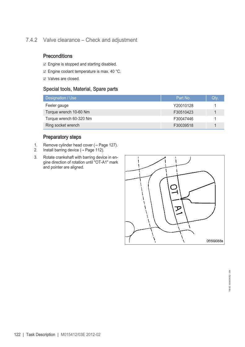
7.4.2 Valve clearance – Check and adjustment
Preconditions☑ Engine is stopped and starting disabled.☑ Engine coolant temperature is max. 40 °C.☑ Valves are closed.
Special tools, Material, Spare partsDesignation / Use Part No. Qty.Feeler gauge Y20010128 1Torque wrench 10-60 Nm F30510423 1Torque wrench 60-320 Nm F30047446 1Ring socket wrench F30039518 1
Preparatory steps1. Remove cylinder head cover (→ Page 127).2. Install barring device (→ Page 112).3. Rotate crankshaft with barring device in en‐
gine direction of rotation until "OT-A1" markand pointer are aligned.
122 | Task Description | M015412/03E 2012-02
TIM
-ID: 0
0000
0435
2 - 0
04

Checking valve bridge balance
Fig. ComponentX Valve bridge with guideY Flying valve bridge
Note: Not applicable for engines with flying valvebridge.
1. Prior to adjusting valve clearance, checkvalve bridge balance on all valve bridges.
2. Use feeler gauge to determine distance be‐tween valve bridge and rocker arm.
M015412/03E 2012-02 | Task Description | 123
TIM
-ID: 0
0000
0435
2 - 0
04

3. Insert feeler gauge with determined valuebetween valve bridge and valve-stem end(A).
4. At the opposite valve-stem end (B), a feelergauge thicker by 0.05 mm should not fit,otherwise adjust valve bridge balance.
Adjusting valve bridge balance
Note: Not applicable for engines with flying valvebridge.
1. Hold valve bridge (1) firmly in position withopen-end wrench and release locknut (2).
2. Use feeler gauge to determine distance be‐tween valve bridge and rocker arm.
3. Place one feeler gauge (of the determinedvalue) each between valve bridge and thetwo valve-stem ends (A) and (B).
4. Turn adjusting screw such that both feelergauges can just be pulled through.
5. Hold adjusting screw securely in positionwith Allen key and fit locknut by hand onvalve bridge.
6. Replace or rectify adjusting screws whichdo not move freely.
124 | Task Description | M015412/03E 2012-02
TIM
-ID: 0
0000
0435
2 - 0
04

7. Tighten locknut (2) to 35 Nm +5 Nm, hold‐ing valve bridge (1) in position with open-end wrench.
8. Recheck valve bridge balance.
Checking valve clearance at two crankshaft positions
Item Explanation1 Cylinder A1 is in firing TDC2 Cylinder A1 is in overlap TDCI Inlet valveX Exhaust valve
M015412/03E 2012-02 | Task Description | 125
TIM
-ID: 0
0000
0435
2 - 0
04

1. Check TDC position of piston in cylinder A1:• If the rocker arms are unloaded on cylinder A1, the piston is in firing TDC.• If the rocker arms are under load on cylinder A1, the piston is in overlap TDC.
2. Check valve clearance with cold engine:• Inlet valves (long rocker arm) = 0.2 mm• Exhaust valves (short rocker arm) = 0.5 mm
3. Check all valve clearances in two crankshaft positions (firing TDC and overlap TDC of cylinder A1) asper diagram.
4. Use feeler gauge to determine the distance between valve bridge and rocker arm.5. If the deviation from the set value exceeds 0.1 mm, adjust valve clearance.
Adjusting valve clearance1. Release locknut (1).2. Insert feeler gauge between valve bridge
and rocker arm.3. Turn adjusting screw (2) with Allen key until
appropriate valve clearance is set.4. Feeler gauge must just pass through the
gap.5. Tighten locknut (1) to 90 +9 Nm, holding
adjusting screw (2) firmly.6. Replace or rectify adjusting screws and/or
locknuts which do not move freely.7. Check valve clearance.
Final steps1. Remove barring device (→ Page 112).2. Install cylinder head cover (→ Page 127).
126 | Task Description | M015412/03E 2012-02
TIM
-ID: 0
0000
0435
2 - 0
04

7.4.3 Cylinder head cover – Removal and installation
Preconditions☑ Engine shut down and starting disabled.
Special tools, Material, Spare partsDesignation / Use Part No. Qty.Gasket (→ Spare Parts Catalog)
Removing cylinder head cover1. Clean cylinder head covers prior to removal
if they are heavily soiled.2. Remove screws.3. Remove cylinder head cover with gasket
from cylinder head.
Installing cylinder head cover1. Clean mating face.2. Check condition of gasket, replace if necessary.3. Place gasket and cylinder head cover on cylinder head.4. Install cylinder head cover.
M015412/03E 2012-02 | Task Description | 127
TIM
-ID: 0
0000
0092
3 - 0
05

7.5 Injection Pump / HP Pump7.5.1 HP pump – Relief bore check
DANGER Unguarded rotating and moving engine components.Risk of serious injury – danger to life!• Take special care when working on a running engine.
WARNING Engine noise above 85 dB (A).Risk of damage to hearing!• Wear ear protectors.
HP pump – Relief bore check1. Check relief bore for oil and fuel discharge
by visual inspection.2. If relief bore is contaminated, stop the en‐
gine, disable engine start, and clean reliefbore.
3. Note the following in case of fluid dis‐charge:• Heavy discharge means continuous dis‐
charge of fluids (leakage). Contact Serv‐ice.
• Minor discharge of fluids up to 10 dropsper day is normal (moistening) and notconsidered a leakage.
128 | Task Description | M015412/03E 2012-02
TIM
-ID: 0
0000
0092
4 - 0
05

7.6 Injection Valve / Injector7.6.1 Injector – Replacement
Special tools, Material, Spare partsDesignation / Use Part No. Qty.Injector (→ Spare Parts Catalog)
Replacing injectoru Remove injector and install new injector (→ Page 130).
M015412/03E 2012-02 | Task Description | 129
TIM
-ID: 0
0000
0002
2 - 0
13

7.6.2 Injector – Removal and installation
Preconditions☑ Engine is stopped and starting disabled.
Special tools, Material, Spare partsDesignation / Use Part No. Qty.Installation and removal device for injector F6790161 1Milling cutter F30452739 1Slotted nut screwdriver F30452578 1Torque wrench, 0.5-5 Nm 0015384230 1Torque wrench, 10-60 Nm F30510423 1Torque wrench, 60-320 Nm F30047446 1Assembly paste (Optimoly Paste White T) 40477 1Grease (Kluthe Hakuform 30-10/Emulgier) X00058060 1Engine oil
WARNING Fuels are combustible.Risk of fire and explosion!• Avoid open flames, electrical sparks and ignition sources.• Do not smoke.
CAUTION Removal of all injectors.Damage to component!• Ensure that the high-pressure fuel accumulator is secured on the engine through two HP lines.
CAUTION Cable damage during operation.Fire hazard!• Twist cables when installing.• Ensure that cables do not touch components.
Preparatory steps1. Shut off fuel supply to engine.2. Remove cylinder head cover (→ Page 127).
130 | Task Description | M015412/03E 2012-02
TIM
-ID: 0
0000
0095
2 - 0
06

Removing injector
Note: Always replace the first and last injectors ofone engine side first. Replace the inner in‐jectors only after the installation of the outerinjectors on this engine side is completed.
1. Undo cable terminal screws (arrow) on in‐jector and remove cable terminals.
2. Remove screw (2) and take off hold-downclamp (1).
3. Remove high-pressure fuel line (5).
4. Install installation/removal device on cylin‐der head.
5. Remove injector with installation/removaldevice.
6. Remove installation/removal device.
M015412/03E 2012-02 | Task Description | 131
TIM
-ID: 0
0000
0095
2 - 0
06

7. Remove sealing ring (1) from injector or usea self-made wire hook to remove it from thecylinder head.
8. Remove O-rings (2) from injector.9. Cover all connections and bores, or seal
with suitable plugs.
Installing injector1. Remove all plugs before installing.2. Coat nozzle retaining nut area of injector
with assembly paste.3. Fit new O-rings on injector and coat with
grease.4. Fit new sealing ring on injector with grease
ensuring correct installation position of seal‐ing ring.
5. Clean sealing surface on cylinder head andprotective sleeve with milling cutter.
6. Insert injector into cylinder head ensuringthat the HP line connection is aligned cor‐rectly.
7. Press in injector with installation/removaldevice.
8. Remove installation/removal device.
132 | Task Description | M015412/03E 2012-02
TIM
-ID: 0
0000
0095
2 - 0
06

9. Use slotted screwdriver to check thrust ringat both line ends for secure seating.
10. Tighten loose thrust ring to the specified tightening torque.
Name Size Type Lubricant Value/Standard
Thrust ring Tightening torque 5 Nm to 10 Nm
11. Coat screw head mating face (2) andthread with engine oil.
12. Place hold-down clamp (1) in correct installation position. Tighten screw (2) with torque wrench to thespecified initial tightening torque.
Name Size Type Lubricant Value/Standard
Screw M12 Preload torque (Engine oil) 5 Nm to 10 Nm
13. Fit O-rings (4) and (6) on high-pressure fuel line (5) and coat with grease.14. Tighten high-pressure fuel line (5) to the specified initial tightening torque.
Name Size Type Lubricant Value/Standard
HP line Preload torque (Engine oil) 5 Nm to 10 Nm
15. Tighten screw (2) to specified torque using a torque wrench.
Name Size Type Lubricant Value/Standard
Screw M12 Tightening torque 100 Nm + 10 Nm
M015412/03E 2012-02 | Task Description | 133
TIM
-ID: 0
0000
0095
2 - 0
06

16. Tighten union nut of connecting piece (limiting valve) to specified torque using a torque wrench.
Name Size Type Lubricant Value/Standard
Union nut Tightening torque 140 Nm + 10 Nm
17. Tighten union nut of connecting piece (injector) to specified torque using a torque wrench.
Name Size Type Lubricant Value/Standard
Union nut Tightening torque 120 Nm +10 Nm
18. Twist cable several times.
19. Insert cable terminals (arrows) underneath screws on injector and tighten screws to specified torque us‐ing a torque wrench.
Name Size Type Lubricant Value/Standard
Screw Tightening torque 1.5 Nm
Final steps1. Install cylinder head cover (→ Page 127).2. Open up fuel supply to engine.
134 | Task Description | M015412/03E 2012-02
TIM
-ID: 0
0000
0095
2 - 0
06

7.7 Fuel System7.7.1 Fuel system – Venting and filling
Preconditions☑ Engine is stopped and starting disabled.
Special tools, Material, Spare partsDesignation / Use Part No. Qty.Filling device B80144852 1Diesel fuel
WARNING Fuels are combustible.Risk of fire and explosion!• Avoid open flames, electrical sparks and ignition sources.• Do not smoke.
Venting and filling LP fuel system1. Connect filling device to connection (2).2. Open vent plugs (6) on filter (5).3. Use hand pump to fill fuel system, providing
pressure of min. 0.5 bar / max. 2.0 bar, untilfuel emerges without bubbles at vent plugs(6).
4. Close vent plugs (6).5. Remove filling device and seal connection
(2).
M015412/03E 2012-02 | Task Description | 135
TIM
-ID: 0
0000
0471
3 - 0
02

Venting and filling HP fuel system1. Connect filling device to connection (3).2. Remove flushing line (4) from HP pump (1).3. Connect return hose of filling device to HP pump (1).4. Unscrew vent line (8) from connection (7).5. Seal connection (7) with sealing cone.
Note: During filling, the opening of the valves in the HP pump must be audible (whistling noise). To open thevalves, minimum pressure of 9 bar must be provided.
6. Fill fuel system with hand pump, providing 9 bar minimum pressure.7. If no whistling sound is audible, pump must be operated faster.8. Filling is completed if:
• Whistling noise is no more audible during pumping;• Bubble-free fuel emerges from the return hose of the filling device.
9. Disconnect return hose from filling device at HP pump (1).10. Connect flushing line (4) to HP pump.11. Remove sealing cone from connection (7).12. Connect vent line (8) at connection (7).13. Remove filling device from connection (3) and seal.
136 | Task Description | M015412/03E 2012-02
TIM
-ID: 0
0000
0471
3 - 0
02

7.8 Fuel Filter7.8.1 Fuel filter – Replacement
Preconditions☑ Engine shut down and starting disabled.
Special tools, Material, Spare partsDesignation / Use Part No. Qty.Oil filter wrench F30379104 1Diesel fuelEasy-change filter (→ Spare Parts Catalog)Plastic ring (→ Spare Parts Catalog)
DANGER Unguarded rotating and moving engine components.Risk of serious injury – danger to life!• Take special care when working on a running engine.
WARNING Fuels are combustible.Risk of fire and explosion!• Avoid open flames, electrical sparks and ignition sources.• Do not smoke.
WARNING Engine noise above 85 dB (A).Risk of damage to hearing!• Wear ear protectors.
CAUTION Damage to component.Serious damage to plant!• For filter replacement with the engine running, operate the engine at low engine load.• The filter which is to be exchanged must be cut out for a brief period only.
M015412/03E 2012-02 | Task Description | 137
TIM
-ID: 0
0000
0491
1 - 0
05

Replacing fuel filter with the enginestopped
1. Cut out the filter to be replaced.A Both filters cut in (operating position)B Left filter cut outC Right filter cut out
2. Unscrew cut-out easy-change filter with oilfilter wrench.
3. Clean sealing face on filter head.4. Check sealing ring on new easy-change fil‐
ter and moisten with fuel.5. Fit SOLAS shield (→ Page 19).6. Screw on easy-change filter and tighten by
hand.7. Set three-way cock to operating position for
both filters (normal position).8. Replace other fuel filters in the same way.9. Vent fuel system (→ Page 135).
Replacing fuel filter with the enginerunning
1. Cut out the filter to be replaced.2. Open threaded vent plugs at filter head of
cut-out filter and ensure that fuel filter is notunder pressure.
3. Close threaded vent plugs.4. Unscrew cut-out easy-change filter with oil
filter wrench.5. Clean sealing face on filter head.6. Check sealing ring on new easy-change fil‐
ter and moisten with fuel.7. Fit SOLAS shield (→ Page 19).8. Screw on easy-change filter and tighten by
hand.9. Set three-way cock to operating position for
both filters (normal position).10. Replace other fuel filters in the same way.
138 | Task Description | M015412/03E 2012-02
TIM
-ID: 0
0000
0491
1 - 0
05

7.8.2 Fuel prefilter – Draining
Preconditions☑ Engine is stopped and starting disabled.
Special tools, Material, Spare partsDesignation / Use Part No. Qty.Diesel fuelGasket (→ Spare Parts Catalog)
WARNING Fuels are combustible.Risk of fire and explosion!• Avoid open flames, electrical sparks and ignition sources.• Do not smoke.
Fuel prefilter – Draining1. Cut out filter to be drained.
I Left filter cut inII Right filter cut in
2. Open threaded vent plug (5) of filter to bedrained.
3. Unlock drain valve (6) by pressing toggleand open it.
4. Drain water and contaminants from filter un‐til pure fuel emerges.
5. Close drain valve (6).6. Remove screws for cover and take off cov‐
er (2).7. Fill filter housing with clean fuel.8. Place new gasket in cover (2).9. Fit cover with gasket and secure it with
screws.10. Cut in the cut-out filter again.11. Close threaded vent plug (5) when fuel
emerges.
M015412/03E 2012-02 | Task Description | 139
TIM
-ID: 0
0000
0492
9 - 0
03

7.8.3 Fuel prefilter ‒ Flushing
Special tools, Material, Spare partsDesignation / Use Part No. Qty.Diesel fuelGasket (→ Spare Parts Catalog)
DANGER Unguarded rotating and moving engine components.Risk of serious injury – danger to life!• Take special care when working on a running engine.
WARNING Fuels are combustible.Risk of fire and explosion!• Avoid open flames, electrical sparks and ignition sources.• Do not smoke.
WARNING Engine noise above 85 dB (A).Risk of damage to hearing!• Wear ear protectors.
Flushing fuel prefilter1. Cut out clogged filter.
I Left filter cut inII Right filter cut in
140 | Task Description | M015412/03E 2012-02
TIM
-ID: 0
0000
0493
7 - 0
14

2. Open threaded vent plug (5) of filter to beflushed.
3. Unlock drain valve (6) by pressing toggle,open it and drain fuel.
Result: Fuel flows from filtered side back to the un‐filtered side, flushing the filter depositsdownwards out of the filter.
4. Close threaded vent plug (5) and drainvalve (6).
Fuel prefilter, topping up with fuel1. Stop engine (→ Page 100) and disable engine start.2. Remove screws for cover and take off cover (2).3. Fill filter housing with clean fuel.4. Place new gasket in cover (2).5. Fit cover with gasket and secure it with screws.6. Check differential pressure (→ Page 142).
Result: If flushing did not lead to an improvement of the differential pressure, replace filter element of fuel prefil‐ter (→ Page 143).
M015412/03E 2012-02 | Task Description | 141
TIM
-ID: 0
0000
0493
7 - 0
14

7.8.4 Fuel prefilter – Differential pressure gauge check and adjustment
DANGER Unguarded rotating and moving engine components.Risk of serious injury – danger to life!• Take special care when working on a running engine.
WARNING Engine noise above 85 dB (A).Risk of damage to hearing!• Wear ear protectors.
Adjusting differential pressuregauge
1. When installing the new filter element: alignadjustable pointer (2) with pressure-indicat‐ing pointer (3) of pressure gauge (1).
2. Check differential pressure.
Checking differential pressure of fuel prefilter1. With the engine running at full load or rated power, read off pressure at gauge (1).2. If differential pressure as indicated between position of adjustable pointer (2) and pressure-indicating
pointer (3) of pressure gauge is ≥ 0.3 bar, flush filter element of the cut-in filter (→ Page 140).
142 | Task Description | M015412/03E 2012-02
TIM
-ID: 0
0000
0492
5 - 0
04

7.8.5 Fuel prefilter – Filter element replacement
Preconditions☑ Engine is stopped and starting disabled.
Special tools, Material, Spare partsDesignation / Use Part No. Qty.Diesel fuelFilter element (→ Spare Parts Catalog)Gasket (→ Spare Parts Catalog)
WARNING Fuels are combustible.Risk of fire and explosion!• Avoid open flames, electrical sparks and ignition sources.• Do not smoke.
Replacing filter element1. Cut out filter to be drained.
I Left filter cut inII Right filter cut in
M015412/03E 2012-02 | Task Description | 143
TIM
-ID: 0
0000
0494
4 - 0
03

2. Open threaded vent plug (5) of contaminat‐ed filter.
3. Unlock drain valve (6) by pressing toggleand open it.
4. Drain water and dirt from filter.5. Close drain valve (6).6. Remove screws securing the cover and
take off cover (2).7. Remove spring housing (4) and filter ele‐
ment (3).8. Insert new filter element (3) and spring
housing (4).9. Fill filter housing with clean fuel.
10. Place new gasket in cover (2).11. Fit cover with gasket and secure it with
screws.12. Cut in the cut-out filter again.13. Close threaded vent plug (5) when fuel
emerges.14. Adjust the differential pressure gauge
(→ Page 142).
144 | Task Description | M015412/03E 2012-02
TIM
-ID: 0
0000
0494
4 - 0
03

7.9 Exhaust Turbocharger7.9.1 Compressor wheel – Cleaning
Preconditions☑ Engine is stopped and starting disabled.
Special tools, Material, Spare partsDesignation / Use Part No. Qty.Cold cleaner X00056750 1
WARNING Compressed airRisk of injury!• Do not direct compressed-air jet at persons.• Wear protective goggles / safety mask and ear protectors.
WARNING Chemical substances.Risk of irritation and chemical burns!• Always obey manufacturer's instructions for use!
CAUTION Incorrect installation of components and lines.Damage to component!• Ensure that components/lines are installed so that they are never under tension or strain.• Ensure correct installation position of components.
CAUTION Unsuitable cleaning tool.Damage to component!• Observe manufacturer's instructions.• Use appropriate cleaning tool.
Preparatory steps1. Drain engine coolant.(→ Page 166)2. Remove air filter.(→ Page 149)3. Remove exhaust system after exhaust turbocharger.4. Remove exhaust flap with actuators.5. Remove air intake.
Compressor wheel – CleaningNote: Do not use wire brush, scraper or similar tools for cleaning!
1. Clean compressor housing with paint brush or smooth brush.2. Clean compressor wheel and bearing housing with cold cleaner.3. Thoroughly blow out all parts with compressed air to remove cold cleaner.
M015412/03E 2012-02 | Task Description | 145
TIM
-ID: 0
0000
3485
2 - 0
01

Final steps1. Install air intake.2. Install exhaust flap with actuators.3. Install exhaust system after exhaust turbocharger.4. Install air filter.(→ Page 149)5. Fill with engine coolant.(→ Page 167)
146 | Task Description | M015412/03E 2012-02
TIM
-ID: 0
0000
3485
2 - 0
01

7.10 Charge-Air Cooling7.10.1 Intercooler – Checking condensate drain line for coolant discharge and
obstruction
DANGER Unguarded rotating and moving engine components.Risk of serious injury – danger to life!• Take special care when working on a running engine.
WARNING Engine noise above 85 dB (A).Risk of damage to hearing!• Wear ear protectors.
WARNING Compressed airRisk of injury!• Do not direct compressed-air jet at persons.• Wear protective goggles / safety mask and ear protectors.
Intercooler – Checking condensatedrain line for coolant discharge andobstruction
1. With the engine running, verify that airemerges from the condensate drain line atdriving end, left and right engine side. If noair escapes:
2. Clean condensate drain line(s) and blowout with compressed air.
3. Replace clogged condensate drain line(s)by new one(s).
4. Install condensate drain line(s).5. If a large amount of coolant is continuously
discharged, the intercooler is leaking. Con‐tact Service.
Emergency measures prior to engine start with a leaking intercooler1. Remove injectors (→ Page 130).2. Bar engine manually (→ Page 112).3. Bar engine with starting system to blow out cylinder chambers (→ Page 113).4. Install injectors (→ Page 130).
M015412/03E 2012-02 | Task Description | 147
TIM
-ID: 0
0000
0533
8 - 0
03

7.11 Air Filter7.11.1 Air filter – Replacement
Special tools, Material, Spare partsDesignation / Use Part No. Qty.Air filter (→ Spare Parts Catalog)
Replacing the air filter1. Remove old air filter and install new air filter (→ Page 149).2. Reset signal ring of contamination indicator (→ Page 152).
148 | Task Description | M015412/03E 2012-02
TIM
-ID: 0
0000
0544
7 - 0
09

7.11.2 Air filter – Removal and installation
Preconditions☑ Engine is stopped and starting disabled.
Air filter – Removal and installation1. Release clamp (2).2. Remove air filter (3) and clamp (2) from
flange of intake housing (1).3. Verify that there are no objects in the flange
of the intake housing (1) and clean it.4. Place new air filter (3) with clamp (2) onto
intake housing (1).5. Tighten clamp (2).
M015412/03E 2012-02 | Task Description | 149
TIM
-ID: 0
0000
0090
4 - 0
09

7.12 Starting Equipment7.12.1 Starter – Condition check
Preconditions☑ Engine is stopped and starting disabled.
Starter – Condition check1. Check securing screws and pressure hose of starter for secure seating and tighten if required.2. Check wiring (→ Page 185).
150 | Task Description | M015412/03E 2012-02
TIM
-ID: 0
0000
1952
3 - 0
02

7.12.2 Air starter – Manual operation
DANGER Unguarded rotating and moving engine components.Risk of serious injury – danger to life!• Before barring or starting the engine, make sure that nobody is in the danger zone.
WARNING Engine noise above 85 dB (A).Risk of damage to hearing!• Wear ear protectors.
Air starter – Manual operation1. Press pushbutton for manual start and hold
it.2. Allow compressed air to enter the air start‐
er, until the engine fires evenly.3. Release pushbutton.
M015412/03E 2012-02 | Task Description | 151
TIM
-ID: 0
0000
0607
6 - 0
03

7.13 Air Intake7.13.1 Contamination indicator – Signal ring position check
Preconditions☑ Engine is stopped and starting disabled.
Checking signal ring position1. If the signal ring is completely visible in the
control window (2), replace air filter(→ Page 148).
2. After installation of new filter, press resetbutton (1).
Result: Engaged piston with signal ring moves backto initial position.
152 | Task Description | M015412/03E 2012-02
TIM
-ID: 0
0000
0548
4 - 0
06

7.13.2 Air flap – Check for ease of movement
Preconditions☑ Engine is stopped and starting disabled.
Checking air flap for easymovement
1. Actuate lever several times to check easeof movement.
Result: The spring must push back the air flap.2. If spring does not return air flap to initial po‐
sition, contact Service.
M015412/03E 2012-02 | Task Description | 153
TIM
-ID: 0
0000
0549
0 - 0
03

7.13.3 Air pipework from air filter to ETC – Check
Special tools, Material, Spare partsDesignation / Use Part No. Qty.Air hose 0229979482 2
Checking air pipework from air filter to ETCItem Findings MeasureVisually check outer layer of airhose.
• Damage• Deformation• Cracks• Cuts• Brittleness• Scuffing
visible
Replace
Check clamp. Damaged Replace
154 | Task Description | M015412/03E 2012-02
TIM
-ID: 0
0000
3435
4 - 0
01

7.14 Lube Oil System, Lube Oil Circuit7.14.1 Engine oil level – Check
Preconditions☑ Engine shut down and starting disabled.
Checking oil level prior to enginestart
1. Withdraw oil dipstick from guide tube andwipe it.
2. Insert oil dipstick into guide tube up to stop,withdraw after approx. 10 seconds andcheck oil level.
Note: After extended standstill, the oil level mayexceed the mark (1) by up to 2 cm. Thiscan be caused by oil flowing from e.g. oil fil‐ter or heat exchanger back to the oil pan.
3. The oil level must reach mark (1) or exceedmark (1) by up to 2 cm.
4. Top up with oil to mark (1) as necessary(→ Page 156).
5. Insert oil dipstick into guide tube up to thestop.
Checking oil level after the engine is stopped1. 5 minutes after stopping the engine, remove oil dipstick from the guide tube and wipe it.2. Insert oil dipstick into guide tube up to stop, withdraw after approx. 10 seconds and check oil level.3. Oil level must be between marks (1) and (2).4. Top up with oil to mark (1) as necessary (→ Page 156).5. Insert oil dipstick into guide tube up to the stop.
M015412/03E 2012-02 | Task Description | 155
TIM
-ID: 0
0000
0093
1 - 0
09

7.14.2 Engine oil – Change
Preconditions☑ Engine is stopped and starting disabled.☑ Engine is at operating temperature.☑ MTU Fluids and Lubricants Specifications (A001061/..) are available.
Special tools, Material, Spare partsDesignation / Use Part No. Qty.Torque wrench, 40-200 Nm F30027337 1Ratchet adapter F30027341 1Engine oilSealing ring (→ Spare Parts Catalog)
WARNING Hot oil.Oil can contain combustion residues which are harmful to health.Risk of injury and poisoning!• Wear protective clothing, gloves, and goggles / safety mask.• Avoid contact with skin.• Do not inhale oil vapor.
Oil change without semirotary hand pump: Draining engine oil at drain plug(s) on oilpan
1. Provide a suitable container in which to collect the engine oil.2. Remove drain plug(s) and drain engine oil.3. Install drain plug(s) with new sealing ring.
Oil change with semirotary hand pump: Engine oil extraction1. Provide a suitable container in which to collect the engine oil.2. Extract all engine oil from oil pan using the semirotary hand pump.
Draining residual oil fromequipment carrier (only withunscheduled engine oil change)
1. Provide a suitable container in which to col‐lect the engine oil.
2. Remove drain plug (1) and drain engine oilfrom engine oil heat exchanger and fromengine oil filter.
3. Remove drain plugs (2) and (3) and drainengine oil.
4. Replace engine oil filter (→ Page 159).5. Install drain plug(s) with new sealing ring.
156 | Task Description | M015412/03E 2012-02
TIM
-ID: 0
0000
3445
5 - 0
01
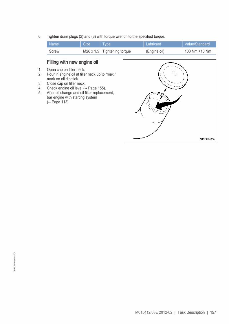
6. Tighten drain plugs (2) and (3) with torque wrench to the specified torque.
Name Size Type Lubricant Value/Standard
Screw M26 x 1.5 Tightening torque (Engine oil) 100 Nm +10 Nm
Filling with new engine oil1. Open cap on filler neck.2. Pour in engine oil at filler neck up to “max.”
mark on oil dipstick.3. Close cap on filler neck.4. Check engine oil level (→ Page 155).5. After oil change and oil filter replacement,
bar engine with starting system(→ Page 113).
M015412/03E 2012-02 | Task Description | 157
TIM
-ID: 0
0000
3445
5 - 0
01

7.14.3 Engine oil – Sample extraction and analysis
Preconditions☑ MTU Fluids and Lubricants Specifications (A001061/..) are available.
Special tools, Material, Spare partsDesignation / Use Part No. Qty.MTU test kit 5605892099/00 1
DANGER Unguarded rotating and moving engine components.Risk of serious injury – danger to life!• Take special care when working on a running engine.
WARNING Hot oil.Oil can contain combustion residues which are harmful to health.Risk of injury and poisoning!• Wear protective clothing, gloves, and goggles / safety mask.• Avoid contact with skin.• Do not inhale oil vapor.
WARNING Engine noise above 85 dB (A).Risk of damage to hearing!• Wear ear protectors.
Engine oil sample extraction andanalysis
1. With the engine running at operating tem‐perature, open screw on flange of centrifu‐gal oil filter by 1 to 2 rotations.
2. Drain approx. 2 liters engine oil to flush outthe oil sludge.
3. Drain approx. 1 liter engine oil into a cleancontainer.
4. Close screw.5. Using the equipment and chemicals of the
MTU test kit, examine oil for:• Dispersing capacity (spot test);• Water content;• Fuel dilution.
158 | Task Description | M015412/03E 2012-02
TIM
-ID: 0
0000
0095
6 - 0
03

7.15 Oil Filtration / Cooling7.15.1 Engine oil filter – Replacement
Special tools, Material, Spare partsDesignation / Use Part No. Qty.Oil filter wrench F30379104 1Engine oilOil filter (→ Spare Parts Catalog)
DANGER Unguarded rotating and moving engine components.Risk of serious injury – danger to life!• Take special care when working on a running engine.
WARNING Engine noise above 85 dB (A).Risk of damage to hearing!• Wear ear protectors.
WARNING Hot oil.Oil can contain combustion residues which are harmful to health.Risk of injury and poisoning!• Wear protective clothing, gloves, and goggles / safety mask.• Avoid contact with skin.• Do not inhale oil vapor.
CAUTION Damage to component.Serious damage to plant!• For filter replacement with the engine running, operate the engine at low engine load.• The filter which is to be exchanged must be cut out for a brief period only.
Oil filter replacement with theengine stopped
1. Stop engine (→ Page 100) and disable en‐gine start.
2. Unscrew oil filter with oil filter wrench.3. Clean sealing face on connecting piece.4. Check condition of the new sealing ring and
coat it with oil.5. Fit SOLAS shield (→ Page 19).6. Screw on and tighten new engine oil filter
by hand.7. Replace other oil filters in the same way.8. After each oil change and filter replace‐
ment, bar engine with starting system(→ Page 113).
9. Check oil level (→ Page 155).
M015412/03E 2012-02 | Task Description | 159
TIM
-ID: 0
0000
3445
8 - 0
01

Oil filter replacement with theengine running
1. To cut out the filter to be replaced, set thethree-way cock to the corresponding posi‐tion.• Position A: Lower filters cut out• Position B: Both filters cut in (normal po‐
sition)• Position C: Upper filters cut out.
2. Unscrew oil filter with oil filter wrench.3. Clean sealing face on connecting piece.4. Check condition of the new sealing ring and
coat it with oil.5. Fit SOLAS shield (→ Page 19).6. Screw on and tighten new engine oil filter
by hand.7. Replace other oil filters in the same way.8. Check oil level (→ Page 155).
160 | Task Description | M015412/03E 2012-02
TIM
-ID: 0
0000
3445
8 - 0
01

7.15.2 Centrifugal oil filter – Cleaning and filter sleeve replacement
Preconditions☑ Engine shut down and starting disabled.
Special tools, Material, Spare partsDesignation / Use Part No. Qty.Filter wrench F30379104 1Torque wrench, 6-50 Nm F30027336 1Ratchet adapter F30027339 1Cold cleaner (Hakutex 60) 50602 1Grease (Kluthe Hakuform 30-10/emulsifier) X00029933 1Filter sleeve (→ Spare Parts Catalog)Sealing ring (→ Spare Parts Catalog)Sealing ring (→ Spare Parts Catalog)
WARNING Hot oil.Oil can contain combustion residues which are harmful to health.Risk of injury and poisoning!• Wear protective clothing, gloves, and goggles / safety mask.• Avoid contact with skin.• Do not inhale oil vapor.
WARNING Compressed airRisk of injury!• Do not direct compressed-air jet at persons.• Wear protective goggles / safety mask and ear protectors.
M015412/03E 2012-02 | Task Description | 161
TIM
-ID: 0
0000
0095
8 - 0
03

Cleaning centrifugal oil filter andreplacing filter sleeve
1. Undo screw (1) and remove.2. Remove clamp (3) and take off hood (2).3. Carefully remove rotor (5) from housing.4. Hold rotor assembly (5) firmly in position
with filter wrench and undo knurled nut (7).5. Take off rotor cap (8).6. Remove filter sleeve (9), stiffener plate (10)
and sealing ring (11).7. Measure thickness of oil residues on filter
sleeve.8. If maximum layer thickness of oil residues
exceeds 30 mm, shorten maintenance in‐terval.
9. Remove standpipe (12) from lower rotorsection (13).
10. Wash hood (2), rotor cap (8), stiffenerplate, (10) standpipe (12), rotor lower sec‐tion (13) and nozzles (14) with cold cleanerand blow out with compressed air. Do notuse sharp objects for cleaning.
11. Check nozzles (14) for obstructions.12. Press standpipe (12) onto rotor lower sec‐
tion (13).13. Insert new filter sleeve (9) with stiffener
plate (10) into rotor cap (8), ensuring thatsmooth surface of filter sleeve (9) faces ro‐tor cap (8).
14. Check sealing ring (11), replace if necessa‐ry. Coat sealing ring with grease and insertin groove of rotor cap (8).
15. Place rotor cap (8) onto standpipe (12).16. Hold rotor assembly (5) firmly in position
with filter wrench and tighten knurlednut (7).
17. Lubricate bearings of rotor (5) with oil, in‐sert into housing (6) and check for ease ofmovement.
18. Check sealing ring (4), replace if necessary.Fit sealing ring on housing (6).
19. Fit hood (2).20. Tighten screw (1) by hand.21. Install clamp (3) and tighten to specified torque using a torque wrench.
Name Size Type Lubricant Value/Standard
Clamp Tightening torque 6 Nm + 1 Nm
22. Tighten screw (1) to specified torque using a torque wrench.
Name Size Type Lubricant Value/Standard
Screw Tightening torque 6 Nm + 1 Nm
162 | Task Description | M015412/03E 2012-02
TIM
-ID: 0
0000
0095
8 - 0
03

7.16 Coolant Circuit, General, High-Temperature Circuit7.16.1 Venting points
Coolant lines on ETC
1 Venting point
Vent line – Cross-distributionn expansion tank
1 Venting point
M015412/03E 2012-02 | Task Description | 163
TIM
-ID: 0
0000
0669
4 - 0
02

7.16.2 Engine coolant – Level check
Preconditions☑ Engine is stopped and starting disabled.☑ MTU Fluids and Lubricants Specifications (A001061/..) are available.
WARNING Coolant is hot and under pressure.Risk of injury and scalding!• Let the engine cool down.• Wear protective clothing, gloves, and goggles / safety mask.
Checking engine coolant level at filler neck:1. Turn breather valve on coolant expansion tank counterclockwise to the first stop and allow pressure to
escape.2. Continue to turn breather valve counterclockwise and remove.3. Check coolant level (coolant must be visible at the lower edge of the cast-in eye).
Checking engine coolant level atremote cooler:
1. Check coolant level (coolant must be visibleat marking plate).
2. Top up coolant if necessary (→ Page 167).3. Check and clean breather valve.4. Place breather valve on filler neck and
close.
Checking engine coolant level via level sensor:1. Switch on engine control system and check readings on the display.2. Top up coolant if necessary (→ Page 167).
164 | Task Description | M015412/03E 2012-02
TIM
-ID: 0
0000
0093
7 - 0
11

7.16.3 Engine coolant – Change
Special tools, Material, Spare partsDesignation / Use Part No. Qty.Engine coolant
Changing engine coolant1. Drain engine coolant (→ Page 166).2. Fill with engine coolant (→ Page 167).
M015412/03E 2012-02 | Task Description | 165
TIM
-ID: 0
0000
0003
6 - 0
28

7.16.4 Engine coolant – Draining
Preconditions☑ Engine is stopped and starting disabled.
WARNING Coolant is hot and under pressure.Risk of injury and scalding!• Let the engine cool down.• Wear protective clothing, gloves, and goggles / safety mask.
Preparatory steps1. Provide an appropriate container to drain the coolant into.2. Switch off preheating unit.
Engine coolant – Draining1. Turn breather valve on coolant expansion
tank counterclockwise up to the first stopand allow pressure to escape.
2. Continue to turn breather valve counter‐clockwise and remove.
3. Draw off separated corrosion inhibitor oil inexpansion tank through the filler neck.
4. Open drain valves and/or drain plugs anddrain coolant at the following points:• At the preheating unit;• At the HT coolant pump elbow;• At the crankcase, left and right side.
5. Additional drain points on 12/16V 4000 Mengines:• T-piece (3) on engine driving end;• Intercooler (2), left and right side;• Carrier-housing cover (1), left and right
side.6. Close all open drain points.7. Place breather valve on filler neck and
close.
166 | Task Description | M015412/03E 2012-02
TIM
-ID: 0
0000
0674
5 - 0
02

7.16.5 Engine coolant – Filling
Preconditions☑ Engine is stopped and starting disabled.☑ MTU Fluids and Lubricants Specifications (A001061/..) are available.
Special tools, Material, Spare partsDesignation / Use Part No. Qty.Engine coolant
WARNING Coolant is hot and under pressure.Risk of injury and scalding!• Let the engine cool down.• Wear protective clothing, gloves, and goggles / safety mask.
CAUTION Cold coolant in hot engine can cause thermal stress.Formation of cracks in components!• Fill / top up coolant only into cold engine.
Preparatory steps1. Turn breather valve of coolant expansion
tank counterclockwise to first stop and allowpressure to escape.
2. Continue to turn breather valve counter‐clockwise and remove.
3. Release the coolant line union on both tur‐bochargers (→ Page 163).
4. Release the coolant line union at the cool‐ant distributor (→ Page 163).
M015412/03E 2012-02 | Task Description | 167
TIM
-ID: 0
0000
0672
7 - 0
04

Filling with coolant using a pump1. Connect appropriate pump with hose to fill‐
ing connection (arrow) on A side or B side.Alternatively:
2. Connect a suitable pump with a hose todrain valve (arrowed).
3. Pump coolant into engine at 0.5 bar mini‐mum until coolant emerges from the loos‐ened unions at the coolant distributor.
4. Tighten the union for coolant line at thecoolant distributor (→ Page 163).
5. Fill expansion tank until overflow edge isreached.
6. Check proper condition of breather valveand clean sealing faces if required.
7. Place breather valve on filler neck andclose.
8. Continue filling process until coolant emerg‐es from the loosened unions at the two tur‐bochargers.
9. Tighten the coolant line union on both tur‐bochargers (→ Page 163).
10. Start engine (→ Page 93).11. After the engine has run at idling speed for
10 seconds, stop engine (→ Page 100).12. Turn breather valve of coolant expansion
tank counterclockwise to first stop and allowpressure to escape.
13. Continue to turn breather valve counter‐clockwise and remove.
14. Check coolant level (→ Page 164) and topup engine coolant as required:
a) Fill in coolant in expansion tank until thecoolant level at top edge of filler neckremains constant.
b) Place breather valve on filler neck andclose.
c) Repeat the steps from "Start engine"(→ Step 9) until coolant no longer needsto be topped up.
d) Disconnect pump and hose.
168 | Task Description | M015412/03E 2012-02
TIM
-ID: 0
0000
0672
7 - 0
04

Filling with coolant through filler neck1. Alternatively: Fill coolant through filler neck on expansion tank until coolant emerges from the loosened
unions at the coolant distribution.2. Tighten the union for coolant line at the coolant distributor (→ Page 163).3. Continue to fill until coolant level remains constant at top edge of filler neck.4. Tighten the coolant line union on both turbochargers (→ Page 163).5. Check proper condition of breather valve and clean sealing faces if required.6. Set breather valve onto filler neck and turn until the first stop to close.7. Start engine (→ Page 93).8. After the engine has run at idling speed for 10 seconds, stop engine (→ Page 100).9. Turn breather valve counterclockwise and remove.
10. Check coolant level (→ Page 164) and top up engine coolant as required:a) Repeat the steps from "Start engine" (→ Step 7) until coolant no longer needs to be topped up.b) Check proper condition of breather valve and clean sealing faces if required.c) Place breather valve on filler neck and close.
M015412/03E 2012-02 | Task Description | 169
TIM
-ID: 0
0000
0672
7 - 0
04

7.16.6 Engine coolant pump – Relief bore check
DANGER Unguarded rotating and moving engine components.Risk of serious injury – danger to life!• Take special care when working on a running engine.
WARNING Engine noise above 85 dB (A).Risk of damage to hearing!• Wear ear protectors.
Engine coolant pump – Relief borecheck
1. Check relief bore for oil and coolant dis‐charge.
2. Stop engine (→ Page 100) and disable en‐gine start, observe general safety instruc‐tions for maintenance and repair.
3. Clean the relief bore with a wire if it is dirty.• Permissible coolant discharge: up to 10
drops per hour.• Permissible oil discharge: up to 5 drops
per hour.4. If discharge exceeds the specified limits:
Contact Service.
170 | Task Description | M015412/03E 2012-02
TIM
-ID: 0
0000
0096
1 - 0
08

7.16.7 Engine coolant – Sample extraction and analysis
Preconditions☑ MTU Fluids and Lubricants Specifications (A001061/..) are available.
Special tools, Material, Spare partsDesignation / Use Part No. Qty.MTU test kit 5605892099/00 1
DANGER Unguarded rotating and moving engine components.Risk of serious injury – danger to life!• Take special care when working on a running engine.
WARNING Coolant is hot and under pressure.Risk of injury and scalding!• Let the engine cool down.• Wear protective clothing, gloves, and goggles / safety mask.
WARNING Engine noise above 85 dB (A).Risk of damage to hearing!• Wear ear protectors.
Engine coolant – Sample extractionand analysis
1. With the engine running, open drain valve(1).
2. Flush sample-extraction point by drainingapprox. 1 liter coolant.
3. Drain approx. 1 liter coolant into a cleancontainer.
4. Close drain valve (1).5. Using the equipment and chemicals of the
MTU test kit, check the coolant for:• Antifreeze concentration• Corrosion inhibitor concentration• pH value.
6. For engine coolant change intervals, referto (→ MTU Fluids and Lubricants Specifica‐tions).
M015412/03E 2012-02 | Task Description | 171
TIM
-ID: 0
0000
0093
8 - 0
06

7.17 Raw Water Pump with Connections7.17.1 Raw water pump – Relief bore check
DANGER Unguarded rotating and moving engine components.Risk of serious injury – danger to life!• Take special care when working on a running engine.
WARNING Engine noise above 85 dB (A).Risk of damage to hearing!• Wear ear protectors.
Checking relief bore on raw waterpump
1. Check relief bore for oil and raw water dis‐charge.
2. Stop engine (→ Page 100) and disable en‐gine start, observe general safety instruc‐tions for maintenance and repair.
3. Clean the relief bore with a wire if it is dirty.• Permissible raw water discharge: up to
10 drops per hour;• Permissible oil discharge: up to 5 drops
per hour.4. If discharge exceeds the specified limits:
Contact Service.
172 | Task Description | M015412/03E 2012-02
TIM
-ID: 0
0000
0728
2 - 0
04

7.18 Battery-Charging Generator7.18.1 Battery-charging generator drive – Coupling condition check
Preconditions☑ Engine shut down and starting disabled.
Checking condition of battery-charging generator drive coupling
1. Remove protective cover.2. Check resilient coupling for cracks and de‐
formation (arrow).3. Contact Service in case of severe deforma‐
tion or cracking.4. Install protective cover.
M015412/03E 2012-02 | Task Description | 173
TIM
-ID: 0
0000
0739
0 - 0
06

7.19 Engine Mounting / Support7.19.1 Engine mounts – Checking securing screws for firm seating
Preconditions☑ Engine is stopped and starting disabled.
Engine mounts – Checking securing screws for firm seating1. Check securing screws for firm seating.2. Tighten loose threaded connections.
174 | Task Description | M015412/03E 2012-02
TIM
-ID: 0
0000
0754
8 - 0
07

7.19.2 Engine mounts – Resilient element check
Preconditions☑ Engine is stopped and starting disabled.☑ Engine is filled with coolant and engine oil.
Special tools, Material, Spare partsDesignation / Use Part No. Qty.Feeler gauge Y20010128 1Calipers Y20001743 1Box wrench F30379609 1Engine oil
Engine mounts – Checking thecondition of resilient elements
1. Wipe rubber surface with dry cloth, do notuse organic detergents.
2. Check resilient elements for crack formationand deformation by visual inspection.
3. Have cracked mounts replaced, contactService.
Engine mounts – Measuring adjustment dimension1. Measure dimension (a) with Vernier caliper.
Note: On new blocked mounts, the adjustment dimension is approx. 28 mm.2. If the measured value of dimension a = 20 mm is lower than the specified value, the resilient element
must be replaced, contact Service.
M015412/03E 2012-02 | Task Description | 175
TIM
-ID: 0
0000
0755
6 - 0
04

Engine mounts – Checking bufferclearance
1. Take off protective cap (2).2. Check marking (1):
• With marking 30: a = 3 mm +0,3 mm.• With marking 40: a = 4 mm +0,3 mm.
3. Check dimension (a) with feeler gauge onmeasuring groove (4).
4. If dimension (a) deviates from the abovespecifications, adjust buffer clearance.
Engine mounts – Buffer clearance adjustment1. Undo nut (3).2. Adjust buffer clearance by turning the central buffer (1).3. Coat mating face of nut (3) and thread of central buffer (1) with a little engine oil. Engine oil must not get
in contact with the rubber elements of the resilient mount.4. Tighten nut (3) to the specified tightening torque securing the central buffer (1) to prevent it turning.
Name Size Type Lubricant Value/Standard
Nut M27 x 2 Tightening torque (Engine oil) 580 Nm +50 Nm
5. Fit protective cap (2).
176 | Task Description | M015412/03E 2012-02
TIM
-ID: 0
0000
0755
6 - 0
04

7.20 Drive Systems, Driving End and Free End (Coupling)7.20.1 Coupling – Condition check
Preconditions☑ Engine is stopped and starting disabled.
Coupling – Condition check1. Remove perforated plate(s).2. Wipe rubber element with dry cloth, do not use organic detergents.3. Check condition of coupling through assembly hole(s), using a torch. Hair cracks in the rubber elements
are permissible.4. If a considerable number of deeper cracks or places with broken-off rubber are found, contact Service.5. Install perforated plate(s).
M015412/03E 2012-02 | Task Description | 177
TIM
-ID: 0
0000
0765
5 - 0
02

7.21 Auxiliary PTO7.21.1 Bilge pump – Relief bore check
DANGER Unguarded rotating and moving engine components.Risk of serious injury – danger to life!• Take special care when working on a running engine.
WARNING Engine noise above 85 dB (A).Risk of damage to hearing!• Wear ear protectors.
Bilge pump – Relief bore check1. Check relief bores for oil and water dis‐
charge.2. Stop engine (→ Page 100) and disable en‐
gine start.3. Clean the relief bores with a wire if dirty.
• Permissible water discharge: Up to 10drops per hour.
• Permissible oil discharge: Up to 5 dropsper hour.
4. If discharge exceeds the specified limits:Contact Service.
178 | Task Description | M015412/03E 2012-02
TIM
-ID: 0
0000
0777
1 - 0
03

7.22 Fuel Supply System7.22.1 Water drain valve – Check
Checking water drain valve1. Open water drain valve.2. Check water outlet for obstructions.3. Close water drain valve.
M015412/03E 2012-02 | Task Description | 179
TIM
-ID: 0
0000
0773
3 - 0
06

7.22.2 Differential pressure gauge – Check
WARNING Fuels are combustible.Risk of fire and explosion!• Avoid open flames, electrical sparks and ignition sources.• Do not smoke.
Checking differential pressure gauge1. Switch on fuel treatment system (→ Page 95).2. Set the alarm points at the differential pressure gauge to zero.
Result: Alarm is initiated with preset delay.3. Reset the alarm points at the differential pressure gauge to the specified values.
180 | Task Description | M015412/03E 2012-02
TIM
-ID: 0
0000
0773
7 - 0
05

7.22.3 Water level probe (3-in-1 rod electrode) – Check
Preconditions☑ System is put out of service and emptied.
WARNING Fuels are combustible.Risk of fire and explosion!• Avoid open flames, electrical sparks and ignition sources.• Do not smoke.
Water level probe (3-in-1 rod electrode) – Check1. Disconnect plug from water level probe.2. Unscrew water level probe.3. Disconnect plug from water level probe.4. Immerse water level probe into a tank filled with water until water level reaches the thread.
Result: Water drain valve opens.5. Leave water level probe in tank.
Result: Alarm must be triggered with the preset delay.6. Disconnect plug from water level probe.7. Remove water level probe from tank.8. Screw in water level probe.9. Connect plug for water level probe.
10. Put the fuel treatment system into operation.
M015412/03E 2012-02 | Task Description | 181
TIM
-ID: 0
0000
0773
9 - 0
06

7.22.4 Pump capacity – Check
WARNING Fuels are combustible.Risk of fire and explosion!• Avoid open flames, electrical sparks and ignition sources.• Do not smoke.
Checking pump capacity1. Install suitable pressure gauge at the neck of the intake side of the pump.2. Check pump pressure.
a) Switch on fuel treatment system (→ Page 95).Note: The pressure limiting valve at the pump might respond and open. Audible noise is caused by overflowing
fuel and can be disregarded.b) Close ball valve at the outlet of the fuel treatment system.c) Check pressure at the pressure gauge in the inlet to the fuel treatment system and note it.
3. Check pump pressure with reduced suction.a) Reduce suction pressure of pump to -0.8 bar with the shutoff valve at the pump intake side.b) Check pressure at the pressure gauge in the inlet to the fuel treatment system and note it.c) Open ball valve at inlet and outlet of fuel treatment system.
4. Calculate wear limit.
Example:Measured value (normal condition). 3 barMeasured value (reduced suction condition). 2.6 barIf the measured value (reduced suction condition) is 10% lower than the measured value (normal con‐dition), the wear limit is reached. Repair pump (contact Service).
182 | Task Description | M015412/03E 2012-02
TIM
-ID: 0
0000
0774
0 - 0
07

7.22.5 Coalescer filter element – Replacement
Preconditions☑ System is switched off and starting disabled.
Special tools, Material, Spare partsDesignation / Use Part No. Qty.Torque wrench, 6-50 Nm F30027336 1Ratchet adapter F30027339 1Diesel fuelEngine oilCoalescer filter element (→ Spare Parts Catalog)Gasket (→ Spare Parts Catalog)
WARNING Fuels are combustible.Risk of fire and explosion!• Avoid open flames, electrical sparks and ignition sources.• Do not smoke.
CAUTION Contamination of components.Damage to component!• Observe manufacturer's instructions.• Check components for special cleanness.
CAUTION Incorrect installation of components and lines.Damage to component!• Ensure that components/lines are installed so that they are never under tension or strain.• Ensure correct installation position of components.
Replacing coalescer filter element1. Close ball valve at the inlet and outlet of the
fuel treatment system.2. Open drain valve.3. Drain fuel.4. Close drain valve.5. Remove nut (9) with washer (2).6. Remove screws (1).7. Remove cover with gasket (10).8. Remove nut (3), washer (8) and end
plate (7).9. Remove coalescer filter element (4).
10. Catch fuel as it runs out.11. Clean housing with a non-linting cloth, rinse
with fuel if required.12. Check housing for corrosion.13. Clean housing sealing surfaces.14. Install coalescer filter element.15. Install end plate (7), washer (8) and nut (3).
M015412/03E 2012-02 | Task Description | 183
TIM
-ID: 0
0000
0773
5 - 0
06

16. Tighten nut (3) to specified tightening torque using a torque wrench.
Name Size Type Lubricant Value/Standard
Nut M16 Tightening torque (Engine oil) 30 Nm +3 Nm
17. Fit gasket (10).18. Install cover.19. Install screw (1), washer (2) and nut (9).20. Tighten nut (9).21. Open ball valve at the inlet and outlet of the fuel treatment system.
Result: The fuel treatment system is ready for operation.
184 | Task Description | M015412/03E 2012-02
TIM
-ID: 0
0000
0773
5 - 0
06

7.23 Wiring (General) for Engine/Gearbox/Unit7.23.1 Engine wiring – Check
Preconditions☑ Engine is stopped and starting disabled.
Special tools, Material, Spare partsDesignation / Use Part No. Qty.Isopropyl alcohol X00058037 1
Engine wiring – Check1. Check securing screws of cable clamps on engine and tighten loose threaded connections.2. Ensure that cables are fixed in their clamps and cannot swing freely.3. Check that cable ties are firm, tighten loose cable ties.4. Replace faulty cable ties.5. Visually inspect the following electrical line components for damage:
• connector housings;• contacts;• sockets;• cables and terminals;• plug-in contacts.
6. (→ Contact Service) if cable conductors are damaged.Note: Close male connectors that are not plugged in with the protective cap supplied.
7. Clean dirty connector housings, sockets and contacts with isopropyl alcohol.8. Ensure that all sensor connectors are securely engaged.
M015412/03E 2012-02 | Task Description | 185
TIM
-ID: 0
0000
0002
9 - 0
18

7.24 Accessories for (Electronic) Engine Governor / ControlSystem
7.24.1 Engine governor and connectors – Cleaning
Preconditions☑ Engine is stopped and starting disabled.
Special tools, Material, Spare partsDesignation / Use Part No. Qty.Connector pliers 0135315483 1Isopropyl alcohol X00058037 1
Cleaning engine governor andconnectors
1. Remove heavy soiling from housing surfacewith isopropyl alcohol.
2. Remove dirt from surface of connectors (1),connector sockets and shrink-formed com‐ponents (2) using a cloth moistened withisopropyl alcohol.
3. Check legibility of cable labels. Clean or re‐place illegible labels.
Cleaning heavily soiled connectorson engine governor
1. Use connector pliers (2) to disengage bayo‐net union nut (4) and withdraw connector(3).
2. Clean connector housings, connector sock‐et housings (1) and all contacts with iso‐propyl alcohol.
3. When connectors, sockets and all contactsare dry: Fit connectors and check enginegovernor plug connections (→ Page 189).
186 | Task Description | M015412/03E 2012-02
TIM
-ID: 0
0000
0094
8 - 0
09

7.24.2 Engine monitoring unit and connectors – Cleaning
Preconditions☑ Engine is stopped and starting disabled.
Special tools, Material, Spare partsDesignation / Use Part No. Qty.Connector pliers 0135315483 1Isopropyl alcohol X00058037 1
Engine monitoring unit andconnectors – Cleaning
1. Remove coarse dirt from housing surfacewith isopropyl alcohol.
2. Remove dirt from surface of connectors (1),connector sockets and shrink sleeves (2)using a cloth moistened with isopropyl alco‐hol.
3. Check legibility of cable labels. Clean or re‐place illegible labels.
Cleaning severely contaminatedEMU connectors
1. Use connector pliers (2) to disengage bayo‐net union nut (4) and withdraw connector(3).
2. Clean connector housings, connector sock‐et housings (1) and all contacts with iso‐propyl alcohol.
3. When connectors, sockets and all contactsare dry: Fit connectors and check plug con‐nections on EMU (→ Page 190).
M015412/03E 2012-02 | Task Description | 187
TIM
-ID: 0
0000
0839
1 - 0
05

7.24.3 Limit switch for start interlock ‒ Check
Preconditions☑ Engine is stopped and starting disabled.
Note: In the OFF position, the limit switch initiates a start interlock, i.e. the engine cannot be started.Checking limit switch for startinterlock
1. Check whether switches (3) and guardplate (1) with engine support (4) are instal‐led on both sides of flywheel housing (2).
2. Check whether both switches (3) are actu‐ated.
3. If switches (3) and/or guard plate (1) withengine support (4) is/are not installed:• Screw on guard plate (1) with engine
support (4).• Then screw on switch (3), ensuring that
the switch (3) is actuated by the guardplate (1).
4. If switch (3) and guard plate (1) are instal‐led, but switch (3) is in the OFF position:• Make certain that the guard plate (1) at
the side of the switch (3) is not distorted.• Release guard plate (1) and screw on
such that the switch (3) is actuated.
188 | Task Description | M015412/03E 2012-02
TIM
-ID: 0
0000
1678
2 - 0
06

7.24.4 Checking engine control unit plug connections
Preconditions☑ Engine shut down and starting disabled.
Special tools, Material, Spare partsDesignation / Use Part No. Qty.Connector pliers 0135315483 1
Checking engine control unit plugconnections
1. Use connector pliers (3) to make certainthat all plug-in connections on engine con‐trol unit are securely seated.
2. Tighten loose bayonet couplings (2) withconnector pliers (3) by turning them clock‐wise until they latch into place.
3. Make sure that unassigned sockets areclosed off with cover caps.
4. Contact Service if bayonet union nut is de‐fective.
M015412/03E 2012-02 | Task Description | 189
TIM
-ID: 0
0000
0094
9 - 0
03

7.24.5 Engine monitoring unit – Plug connection check
Preconditions☑ Engine is stopped and starting disabled.
Special tools, Material, Spare partsDesignation / Use Part No. Qty.Connector pliers 0135315483 1
Checking engine monitoring unitplug connections
1. Use connector pliers (3) to make certainthat all engine monitoring unit plug connec‐tions are securely seated.
2. Tighten loose bayonet union nuts (2) withconnector pliers (3) by turning them clock‐wise until they lock into place.
3. Make sure that unassigned sockets areclosed off with cover caps.
4. If bayonet couplings are defective, contactService.
190 | Task Description | M015412/03E 2012-02
TIM
-ID: 0
0000
0839
4 - 0
03

7.24.6 Engine control unit – Removal and installation
Preconditions☑ Engine is stopped and starting disabled.
Special tools, Material, Spare partsDesignation / Use Part No. Qty.Connector pliers 0135315483 1Covering caps for Cannon sockets
Removing control unit from engine1. Note or mark assignment of cables to con‐
nector sockets.2. Use connector pliers (2) to disengage the
bayonet union nuts (4) of the connectors (3)by turning them counterclockwise.
3. Remove all connectors.4. Close connector sockets with appropriate
covering caps (1).
M015412/03E 2012-02 | Task Description | 191
TIM
-ID: 0
0000
0848
7 - 0
04

5. Disconnect ground strap from engine con‐trol unit grounding stud (7).
6. If the screws (4) are easily accessible:1. Remove screws (4).2. Remove engine control unit housing (3)
from mounting plates (2).3. Unscrew mounting plates (2), cable
shock absorbers (5) and further fasten‐ing parts (6) as one unit from engine.
7. If the screws (4) are not easily accessible:1. Unscrew screws (1).2. Remove engine control unit housing (3)
together with mounting plates (2).3. Unscrew cable shock absorbers (5) and
further fastening parts (6) as one unitfrom engine.
Installing engine control unit on engine1. Install in reverse order. Ensure correct assignment of plugs and sockets.2. Use connector pliers to turn the bayonet union nuts of the connectors clockwise until they lock into place.
192 | Task Description | M015412/03E 2012-02
TIM
-ID: 0
0000
0848
7 - 0
04

7.24.7 LOP – Visual inspection
Preconditions☑ Engine is stopped and starting disabled.
Preparatory steps1. If READY FOR OPERATION button is illuminated brightly, press switch briefly.
Result: READY FOR OPERATION button returns to basic brightness.2. Switch master power switch to OFF.3. Disconnect battery in accordance with battery manufacturer's instructions.
Checking housing and internalassemblies for secure seating
1. Open LOP front door.2. Check securing screws (1, 3, 4, 7) for firm
seating. Tighten loose threaded connec‐tions.
3. Check internal assemblies for firm seating,this applies in particular to printed circuitboard (2) and PIMs (5, 6). Tighten loosethreaded connections.
4. Close LOP front door.
Checking plug connections1. Check all connected cables to verify that
the two securing elements (1) are engagedon the lugs (2) so that the respective maleconnector (3) is held firmly in place in thesocket.
2. If this is not the case, press the securing el‐ements (1) concerned in the direction of thearrow until they engage noticeably.
M015412/03E 2012-02 | Task Description | 193
TIM
-ID: 0
0000
3118
9 - 0
02
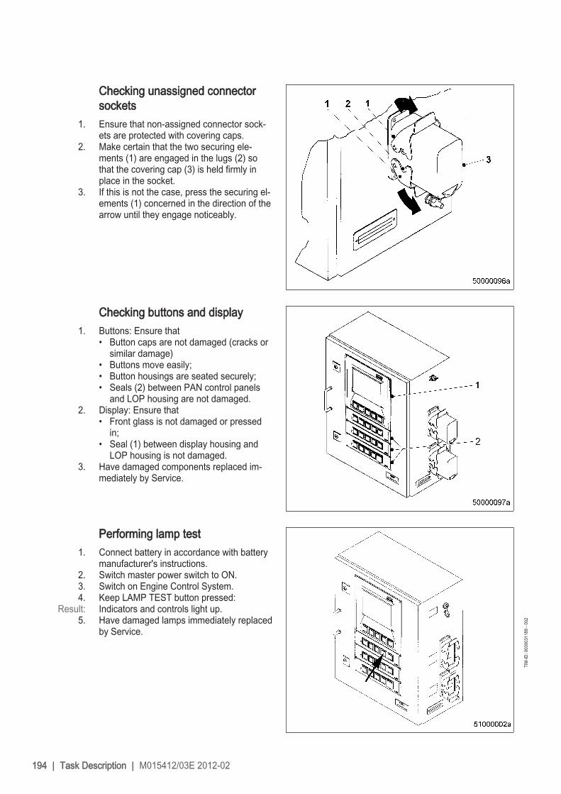
Checking unassigned connectorsockets
1. Ensure that non-assigned connector sock‐ets are protected with covering caps.
2. Make certain that the two securing ele‐ments (1) are engaged in the lugs (2) sothat the covering cap (3) is held firmly inplace in the socket.
3. If this is not the case, press the securing el‐ements (1) concerned in the direction of thearrow until they engage noticeably.
Checking buttons and display1. Buttons: Ensure that
• Button caps are not damaged (cracks orsimilar damage)
• Buttons move easily;• Button housings are seated securely;• Seals (2) between PAN control panels
and LOP housing are not damaged.2. Display: Ensure that
• Front glass is not damaged or pressedin;
• Seal (1) between display housing andLOP housing is not damaged.
3. Have damaged components replaced im‐mediately by Service.
Performing lamp test1. Connect battery in accordance with battery
manufacturer's instructions.2. Switch master power switch to ON.3. Switch on Engine Control System.4. Keep LAMP TEST button pressed:
Result: Indicators and controls light up.5. Have damaged lamps immediately replaced
by Service.
194 | Task Description | M015412/03E 2012-02
TIM
-ID: 0
0000
3118
9 - 0
02

8 Appendix AAbbreviations
Abbrevia‐tion
Meaning Explanation
ADEC Advanced Diesel Engine Control Engine governorAL Alarm Alarm (general)ANSI American National Standards Institute Governing body for US American standardsATL Abgasturbolader Exhaust turbochargerBR Baureihe SeriesBV Betriebsstoffvorschrift Fluids and Lubricants Specifications, MTU Publica‐
tion No. A01061/..CAN Controller Area Network Data bus system, bus standardCPP Controllable Pitch PropellerDIN Deutsches Institut für Normung e. V German Standardization Organization, at the same
time identifyer of German standards ("Deutsche In‐dustrie-Norm")
DIS Display unitDL Default Lost Alarm: Default CAN bus failureECS Engine Control SystemECU Engine Control Unit Engine governorEDM Engine Data ModuleEIM Engine Interface Module Interface to engine monitoring systemEMU Engine Monitoring UnitETK Ersatzteilkatalog Spare Parts CatalogFPP Fixed Pitch PropellerGCU Gear Control UnitGMU Gear Monitoring UnitHAT Harbour Acceptance TestHI High Alarm: Measured value exceeds 1st maximum limitHIHI High High Alarm: Measured value exceeds 2nd maximum lim‐
itHT High TemperatureICFN ISO - Continuous rating - Fuel stop
power - NetPower specification in accordance with DIN-ISO3046-7
IDM Interface Data ModuleIMO International Maritime Organisation International maritime organisationISO International Organization for Stand‐
ardizationKGS Kraftgegenseite Engine free end in accordance with DIN ISO 1204KS Kraftseite Engine driving end in accordance with DIN ISO
1204
M015412/03E 2012-02 | Appendix A | 195

Abbrevia‐tion
Meaning Explanation
LCD Liquid Crystal Display, Liquid CrystalDevice
LCU Local Control Unit LOP subassemblyLED Light Emitting DiodeLMU Local Monitoring Unit LOP subassemblyLO Low Alarm: Measured value lower than 1st minimum
limitLOLO Low Low Alarm: Measured value lower than 2nd minimum
limitLOP Local Operating PanelLOS Local Operating StationMCS Monitoring and Control SystemMG Message MessageMPU Microprocessor Unit, Microprocessing
UnitOT Oberer Totpunkt Top dead centerP-xyz Pressure-xyz Pressure measuring point xyzPAN Panel Operating panelPCU Propeller Control UnitPIM Peripheral Interface ModuleRCS Remote Control SystemRL Redundancy Lost Alarm: Redundant CAN bus failureSAE Society of Automotive Engineers U.S. standardization organizationSAT Sea Acceptance TestSD Sensor Defect Alarm: Sensor failureSDAF Shut Down Air FlapsSS Safety System Indicated alarm is initiated by the safety systemSSK Schnellschlussklappe(n) Shut-down air flap(s)T-xyz Temperature-xyz Temperature measuring point xyzTD Transmitter Deviation Alarm: Sensor comparison faultUT Unterer Totpunkt Bottom dead centerVS Voith Schneider Voith-Schneider driveWJ Water JetWZK Werkzeugkatalog Tools CatalogZKP Zugehörigkeit-Kategorie-Parameter Numbering plan for ADEC ECU signals
MTU contacts/service partners
ServiceOur worldwide sales network with its subsidiaries, sales offices, representatives and customer servicecenters ensures fast and direct support on site and the high availability of our products.
196 | Appendix A | M015412/03E 2012-02

Local supportExperienced and qualified specialists place their knowledge and expertise at your disposal.
For locally available support, go to the MTU internet site: http://www.mtu-online.com
24h hotlineWith our 24h hotline and the outstanding flexibility of our service staff, we are always ready to assist you- either during operation, for preventive maintenance, corrective work in case of malfunction or changedoperating conditions, or for spare parts supply.Your contact at Headquarters:[email protected]
Spare parts serviceFast, simple and correct identification of spare parts for your drive system or vehicle fleet. The right sparepart at the right time at the right place.With this aim in mind, we can call on a globally networked spares logistics system- a central depot at Headquarters, as well as decentralized depots among our subsidiaries, representa‐tives and contractual workshops.Your contact at Headquarters:E-mail: [email protected]: +49 7541 908555Fax: +49 7541 908121
M015412/03E 2012-02 | Appendix A | 197

9 Appendix B9.1 Special Tools
Barring device
Part No.: F6555766Qty.:Used in:
1 7.1.1 Engine – Barring manually (→ Page 112)
Box wrench
Part No.: F30379609Qty.:Used in:
1 7.19.2 Engine mounts – Resilient element check (→ Page 175)
Calipers
Part No.: Y20001743Qty.:Used in:
1 7.19.2 Engine mounts – Resilient element check (→ Page 175)
Connector pliers
Part No.: 0135315483Qty.:Used in:
1 7.24.1 Engine governor and connectors – Cleaning (→ Page 186)
Qty.:Used in:
1 7.24.2 Engine monitoring unit and connectors – Cleaning (→ Page 187)
Qty.:Used in:
1 7.24.4 Checking engine control unit plug connections (→ Page 189)
Qty.:Used in:
1 7.24.5 Engine monitoring unit – Plug connection check (→ Page 190)
Qty.:Used in:
1 7.24.6 Engine control unit – Removal and installation (→ Page 191)
Feeler gauge
Part No.: Y20010128Qty.:Used in:
1 7.4.2 Valve clearance – Check and adjustment (→ Page 122)
Qty.:Used in:
1 7.19.2 Engine mounts – Resilient element check (→ Page 175)
Filling device
Part No.: B80144852Qty.:Used in:
1 7.7.1 Fuel system – Venting and filling (→ Page 135)
198 | Appendix B | M015412/03E 2012-02
DCL-
ID: 0
0000
1667
1 - 0
01

Filter wrench
Part No.: F30379104Qty.:Used in:
1 7.15.2 Centrifugal oil filter – Cleaning and filter sleeve replacement (→ Page 161)
Installation and removal device for injector
Part No.: F6790161Qty.:Used in:
1 7.6.2 Injector – Removal and installation (→ Page 130)
Milling cutter
Part No.: F30452739Qty.:Used in:
1 7.6.2 Injector – Removal and installation (→ Page 130)
MTU test kit
Part No.: 5605892099/00Qty.:Used in:
1 7.14.3 Engine oil – Sample extraction and analysis (→ Page 158)
Qty.:Used in:
1 7.16.7 Engine coolant – Sample extraction and analysis (→ Page 171)
Oil filter wrench
Part No.: F30379104Qty.:Used in:
1 7.8.1 Fuel filter – Replacement (→ Page 137)
Qty.:Used in:
1 7.15.1 Engine oil filter – Replacement (→ Page 159)
Ratchet adapter
Part No.: F30027340Qty.:Used in:
1 7.3.2 Crankcase breather – Oil separator replacement, diaphragm check and replace‐ment (→ Page 119)
Ratchet adapter
Part No.: F30027341Qty.:Used in:
1 7.14.2 Engine oil – Change (→ Page 156)
Ratchet adapter
Part No.: F30027339Qty.:Used in:
1 7.15.2 Centrifugal oil filter – Cleaning and filter sleeve replacement (→ Page 161)
Qty.:Used in:
1 7.22.5 Coalescer filter element – Replacement (→ Page 183)
M015412/03E 2012-02 | Appendix B | 199
DCL-
ID: 0
0000
1667
1 - 0
01

Ratchet head with extension
Part No.: F30006212Qty.:Used in:
1 7.1.1 Engine – Barring manually (→ Page 112)
Rigid endoscope
Part No.: Y20097353Qty.:Used in:
1 7.2.1 Cylinder liner – Endoscopic examination (→ Page 114)
Ring socket wrench
Part No.: F30039518Qty.:Used in:
1 7.4.2 Valve clearance – Check and adjustment (→ Page 122)
Slotted nut screwdriver
Part No.: F30452578Qty.:Used in:
1 7.6.2 Injector – Removal and installation (→ Page 130)
Steam jet cleaner
Part No.: -Qty.:Used in:
1 4.20 Plant – Cleaning (→ Page 106)
Torque wrench 10-60 Nm
Part No.: F30510423Qty.:Used in:
1 7.4.2 Valve clearance – Check and adjustment (→ Page 122)
Torque wrench 60-320 Nm
Part No.: F30047446Qty.:Used in:
1 7.4.2 Valve clearance – Check and adjustment (→ Page 122)
Torque wrench, 0.5-5 Nm
Part No.: 0015384230Qty.:Used in:
1 7.6.2 Injector – Removal and installation (→ Page 130)
Torque wrench, 10-60 Nm
Part No.: F30510423Qty.:Used in:
1 7.6.2 Injector – Removal and installation (→ Page 130)
200 | Appendix B | M015412/03E 2012-02
DCL-
ID: 0
0000
1667
1 - 0
01

Torque wrench, 40-200 Nm
Part No.: F30027337Qty.:Used in:
1 7.14.2 Engine oil – Change (→ Page 156)
Torque wrench, 6-50 Nm
Part No.: F30027336Qty.:Used in:
1 7.22.5 Coalescer filter element – Replacement (→ Page 183)
Torque wrench, 6-50 Nm
Part No.: F30027336Qty.:Used in:
1 7.3.2 Crankcase breather – Oil separator replacement, diaphragm check and replace‐ment (→ Page 119)
Qty.:Used in:
1 7.15.2 Centrifugal oil filter – Cleaning and filter sleeve replacement (→ Page 161)
Torque wrench, 60-320 Nm
Part No.: F30047446Qty.:Used in:
1 7.6.2 Injector – Removal and installation (→ Page 130)
M015412/03E 2012-02 | Appendix B | 201
DCL-
ID: 0
0000
1667
1 - 0
01

9.2 Index12V 4000 M70 engine data: engine-mounted heat ex‐
changer, EPA stage 2 4112V 4000 M70 engine data: IMO -20%, engine-mounted
heat exchanger, copper-based alloy intercooler 3812V 4000 M70 engine data: IMO -20%, separate heat
exchanger, copper-based alloy intercooler 3512V 4000 M70 engine data: separate heat exchanger,
EPA stage 2 4412V 4000 M71 engine data: IMO, engine-mounted heat
exchanger, copper-based alloy intercooler 6812V 4000 M71 engine data: IMO, separate heat ex‐
changer, copper-based alloy intercooler 6512V 4000 M71 engine data: IMO, separate heat ex‐
changer, copper-based alloy intercooler, intake airtemperature 45° 71
16V 4000 M70 engine data: engine-mounted heat ex‐changer, EPA stage 2 59
16V 4000 M70 engine data: IMO -20%, engine-mountedheat exchanger, copper-based alloy intercooler 56
16V 4000 M70 engine data: IMO -20%, separate heatexchanger, copper-based alloy intercooler 53
16V 4000 M70 engine data: IMO, engine-mounted heatexchanger, copper-based alloy intercooler 50
16V 4000 M70 engine data: IMO, separate heat ex‐changer, copper-based alloy intercooler 47
16V 4000 M70 engine data: separate heat exchanger,EPA stage 2 62
16V 4000 M71 engine data: IMO, engine-mounted heatexchanger, copper-based alloy intercooler 77
16V 4000 M71 engine data: IMO, separate heat ex‐changer, copper-based alloy intercooler 74
16V 4000 M71 engine data: IMO, separate heat ex‐changer, copper-based alloy intercooler, intake airtemperature 45° 80
8V 4000 M70 engine data: engine-mounted heat ex‐changer, IMO 32
8V 4000 M70 engine data: IMO, separate heat exchang‐er, copper-based alloy intercooler 29
AAbbreviations 195After stopping the engine 104Air filter– Installation 149– Removal 149– Replacement 148Air flap– Check for ease of movement 153Air pipework from air filter to ETC– Check 154Air starter– Manual operation 151Auxiliary materials, fire prevention and environmental
protection 14
BBattery-charging generator drive– Coupling condition check 173Bilge pump– Relief bore check 178
CCentrifugal oil filter– Cleaning and filter sleeve replacement 161Checks– Prior to start-up 90Clutch – Disengaging from LOP 98Clutch – Engaging from LOP 97Coalescer– filter element
– Replacement 183Coalescer filter element– Replacement 183Compressor wheel– Cleaning 145Connectors– Cleaning 186, 187Contact persons 196Contamination indicator– Signal ring position check 152Coupling – Condition check 177Crankcase breather– Diaphragm check and replacement 119– Oil separator check 118– Oil separator replacement 119Cylinder– Designations 18Cylinder head cover– Removal and installation 127Cylinder liner– Endoscopic examination 114– Instructions and comments on endoscopic and visual
examination 116
DDifferential pressure gauge– Check 180
EEmergency stop from LOP 102Engine– Barring with starting system 113– Wiring check 185Engine control unit– Removal and installation 191Engine coolant– Change 165– Filling 167– Level check 164– Sample extraction and analysis 171
202 | Appendix B | M015412/03E 2012-02
DCL-
ID: 0
0000
1667
1 - 0
01

Engine coolant pump– Relief bore check 170Engine coolant – Draining 166Engine emergency stop at BlueLine automation system
(control stand) 103Engine governor– Cleaning 186Engine monitoring unit– Cleaning 187– Plug connection check 190Engine mounts– Resilient element check 175Engine mounts– Checking securing screws for firm seating 174Engine oil– Change 156– Sample extraction and analysis 158Engine oil filter– Replacement 159Engine oil level– Check 155Engine side– Designations 18Engine starting from the BlueLine automation system
(control stand) 94Engine wiring– Check 185Engine – barring manually 112Engine – Main dimensions 84Engine – Overview 26, 27Engine – Preparations for putting into operation– After extended out-of-service periods (>3 months)
87
FFiring order 83Fuel– Prefilter
– Flushing 140– treatment system
– Shutdown 105– Switching on 95
Fuel filter– Replacement 137Fuel prefilter– Differential pressure gauge
– Check and adjustment 142– Draining 139– Filter element
– Replacement 143– Flushing 140Fuel system – Venting and filling 135Fuel treatment system– Putting into operation 91– Shutdown 105– Switching on 95
GGeneral conditions 6
HHP pump– Relief bore check 128
IInjector– Installation 130– Removal 130– Replacement 129Inspection port cover– Explosion hazard 10Intercooler – Checking condensate drain line for coolant
discharge and obstruction 147
LLimit switch for start interlock– Check 188LOP– Visual inspection 193LOP fault messages 111LOP – Controls 85
MMaintenance work– Safety regulations 11MTU contact persons 196
OOperation– Safety regulations 9Operational checks 96
PPersonnel and organizational requirements 7Plant– Cleaning 106Product description 19Pump capacity– Check 182Putting into operation– Fuel treatment system 91Putting the engine into operation– After scheduled out-of-service-period 88
RRaw water pump– Relief bore check 172Repair work– Safety regulations 11
SSafety instructions 17Safety regulations 9, 11Service partners 196Starting the engine from LOP 93Startup– Safety regulations 9Stopping the engine at the BlueLine automation system
(control stand) 101
M015412/03E 2012-02 | Appendix B | 203
DCL-
ID: 0
0000
1667
1 - 0
01

Stopping the engine from LOP 100
TTasks– After extended out-of-service periods 89Tasks after extended out-of-service periods (>3 weeks)
89Transport 8Troubleshooting 108
VValve clearance– Adjustment 122– Check 122Valve gear– Lubrication 121Venting points 163
WWater drain valve– Check 179Water level probe (3-in-1 rod electrode)– Check 181Waterjet – Flushing from LOP (optional) 99Wiring - engine– Check 185
204 | Appendix B | M015412/03E 2012-02
DCL-
ID: 0
0000
1667
1 - 0
01


