Operating instructions and spare ... - Gema Switzerland GmbH
43
1012 279 En Translation of the original operating instructions Operating instructions and spare parts list Manual coating equipment OptiFlex 2 F Spray
Transcript of Operating instructions and spare ... - Gema Switzerland GmbH

1012 279 En
Translation of the original operating instructions
Operating instructions and spare parts list
Manual coating equipment OptiFlex 2 F Spray
V 03/18
Documentation Manual coating equipment OptiFlex 2 F Spray
© Copyright 2016 Gema Switzerland GmbH
All rights reserved.
This publication is protected by copyright. Unauthorized copying is prohib-ited by law. No part of this publication may be reproduced, photocopied, translated, stored on a retrieval system or transmitted in any form or by any means for any purpose, neither as a whole nor partially, without the express written consent of Gema Switzerland GmbH.
Gema, EquiFlow, MagicCompact, MagicCylinder, OptiCenter, OptiFlex, OptiGun, OptiSelect and OptiStar are registered trademarks of Gema Switzerland GmbH.
ClassicLine, ClassicStandard, ClassicOpen, DVC (Digital Valve Control), GemaConnect, MagicControl, MagicPlus, MonoCyclone, MRS, MultiCol-or, MultiStar, OptiAir, OptiControl, OptiColor, OptiFeed, OptiFlow, Opti-Hopper, OptiMove, OptiSieve, OptiSpeeder, OptiSpray, PCC (Precise Charge Control), RobotGun, SIT (Smart Inline Technology) and SuperCo-rona are registered trademarks of Gema Switzerland GmbH.
All other product names are trademarks or registered trademarks of their respective holders.
Reference is made in this manual to different trademarks or registered trademarks. Such references do not mean that the manufacturers con-cerned approve of or are bound in any form by this manual. We have en-deavored to retain the preferred spelling of the trademarks, and registered trademarks of the copyright holders.
To the best of our knowledge and belief, the information contained in this publication was correct and valid on the date of publication. Gema Swit-zerland GmbH makes no representations or warranties with respect to the contents or use of this publication, and reserves the right to revise this publication and make changes to its content without prior notice.
For the latest information about Gema products, visit www.gemapowdercoating.com.
For information regarding patents, visit www.gemapowdercoating.com/patents or www.gemapowdercoating.us/patents.
Printed in Switzerland
Gema Switzerland GmbH Mövenstrasse 17 9015 St.Gallen Switzerland
Phone: +41-71-313 83 00 Fax.: +41-71-313 83 83
E-mail: [email protected]
V 03/18
OptiFlex 2 F Spray Table of contents • 1
Table of contents
About this instructions 3
General information ................................................................................................ 3 Keeping the manual ................................................................................................ 3 Safety symbols (pictograms) ................................................................................... 3
Structure of Safety Notes ........................................................................... 4 Presentation of the contents ................................................................................... 4
Figure references in the text ...................................................................... 4
Safety 5
Intended use ........................................................................................................... 5 Product-specific safety information ......................................................................... 5
Product description 11
Field of application ................................................................................................ 11 Utilization .................................................................................................. 11 Versions ................................................................................................... 12 Reasonably foreseeable misuse .............................................................. 13
Design and function .............................................................................................. 13 Structure ................................................................................................... 13
Technical Data ...................................................................................................... 14 Connectable guns .................................................................................... 14 Powder output (reference values) ............................................................ 14 Air flow rates ............................................................................................ 14 Electrical data .......................................................................................... 15 Pneumatic data ........................................................................................ 15 Dimensions .............................................................................................. 15 Processible powders ................................................................................ 15
Scope of delivery .................................................................................................. 16 OptiFlex 2 F Spray ................................................................................... 16
Typical properties – Characteristics of the functions ............................................ 16 Processing of the powder from the fluidized powder container ............... 16 Freely rotating head piece ....................................................................... 16
Start-up 17
Preparation for start-up ......................................................................................... 17 Basic conditions ....................................................................................... 17
Set-up .................................................................................................................... 17 Assembly guide ..................................................................................................... 18 Connection instructions ......................................................................................... 19
Initial start-up 21
Set head piece ...................................................................................................... 22 Setting the device type .......................................................................................... 22 Operation .............................................................................................................. 23
Coating ..................................................................................................... 23 Setting the background illumination ......................................................... 27
V 03/18
2 • Table of contents OptiFlex 2 F Spray
Color change ........................................................................................................ 28 General information ................................................................................. 28
Shutdown .............................................................................................................. 29
Cleaning and maintenance 31
Daily maintenance ................................................................................................ 31 Weekly maintenance ............................................................................................ 31 If in disuse for several days .................................................................................. 31
Powder hose rinsing ................................................................................ 31 Cleaning ................................................................................................................ 32
Cleaning the powder hopper ................................................................... 32 Cleaning the OptiSelect GM03 manual powder gun ............................... 33
Maintenance and cleaning of the filter unit ........................................................... 34 Replacing the filter element ..................................................................... 34
Troubleshooting 35
General information .............................................................................................. 35
Spare parts list 37
Ordering spare parts ............................................................................................. 37 OptiFlex 2 F Spray – Spare parts list ................................................................... 38 OptiFlex 2 F Spray – Spare parts ......................................................................... 39 Pneumatic group .................................................................................................. 40

V 03/18
OptiFlex 2 F Spray About this instructions • 3
About this instructions
Pos: 11 /Kapitel/Über diese Anleitung ++++ Für alle Anleitungen ++++/Allgemeines @ 1\mod_1452610204952_6.docx @ 22324 @ 2 @ 1
General information This operating manual contains all important information you will need to work with the OptiFlex 2 F Spray. It will safely guide you through the start-up process and give you references and tips for the optimal use of your new powder coating system.
Information about the functional mode of the individual system compo-nents should be referenced in the respective enclosed documents.
Pos: 12 /Kapitel/Über diese Anleitung ++++ Für alle Anleitungen ++++/Anleitung aufbewahren @ 1\mod_1452679788745_6.docx @ 22535 @ 2 @ 1
Keeping the manual Please keep this Manual ready for later use or if there should be any que-ries.
Pos: 13 /Kapitel/Über diese Anleitung ++++ Für alle Anleitungen ++++/Sicherheitssymbole (Piktogramme) @ 1\mod_1452781244678_6.docx @ 23721 @ 2 @ 1
Safety symbols (pictograms)
The following contains a list of warnings with their meanings found in the Gema operating instructions. Apart from the regulations in the relevant operating instructions, the general safety precautions must also be fol-lowed .
DANGER
Indicates a hazardous situation which,
if not avoided, will result in death or serious injury.
WARNING
Indicates a potentially hazardous situation which,
if not avoided, could result in death or serious injury.
CAUTION
Indicates a potentially hazardous situation which,
if not avoided, could result in minor or moderate injury.
V 03/18
4 • About this instructions OptiFlex 2 F Spray
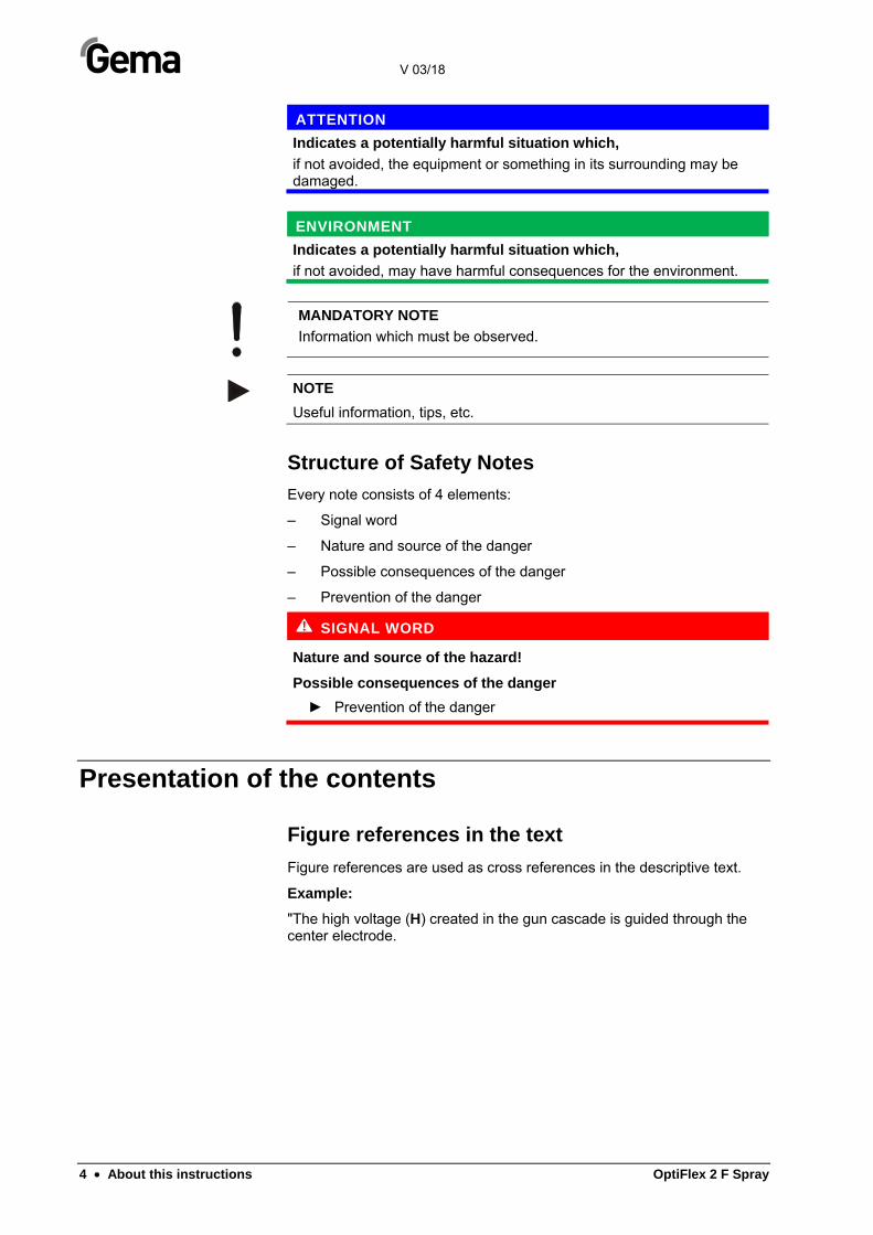
ATTENTION
Indicates a potentially harmful situation which,
if not avoided, the equipment or something in its surrounding may be damaged.
ENVIRONMENT
Indicates a potentially harmful situation which,
if not avoided, may have harmful consequences for the environment.
MANDATORY NOTE
Information which must be observed.
NOTE
Useful information, tips, etc.
Structure of Safety Notes
Every note consists of 4 elements:
– Signal word
– Nature and source of the danger
– Possible consequences of the danger
– Prevention of the danger
SIGNAL WORD
Nature and source of the hazard!
Possible consequences of the danger
► Prevention of the danger
Pos: 14 /Kapitel/Über diese Anleitung ++++ Für alle Anleitungen ++++/Darstellung des Inhalts @ 1\mod_1452784296568_6.docx @ 23800 @ 23 @ 1
Presentation of the contents
Figure references in the text
Figure references are used as cross references in the descriptive text.
Example:
"The high voltage (H) created in the gun cascade is guided through the center electrode.
V 03/18
OptiFlex 2 F Spray Safety • 5
Safety
Pos: 17 /Kapitel/Sicherheit/Bestimmungsgemässe Verwendung/Bestimmungsgemässe Verwendung @ 1\mod_1452781705430_6.docx @ 23747 @ 2 @ 1
Intended use
– This product is built to the latest specification and conforms to the recognized technical safety regulations and is designed for the nor-mal application of powder coating.
– Any other use is considered non-compliant. The manufacturer shall not be liable for damage resulting from such use; the user bears sole responsibility for such actions. If this product is to be used for other purposes or other substances outside of our guidelines then Gema Switzerland GmbH should be consulted.
– Observance of the operating, service and maintenance instructions specified by the manufacturer is also part of conformity of use. This product should only be used, maintained and started up by trained personnel, who are informed about and are familiar with the possible hazards involved.
– Start-up (i.e. the execution of intended operational tasks) is forbid-den until it has been established that this product has been set up and wired according to the guidelines for machinery. The standard "Machine safety" must also be observed.
– Unauthorized modifications to the product exempt the manufacturer from any liability from resulting damage.
– The relevant accident prevention regulations, as well as other gen-erally recognized safety regulations, occupational health and struc-tural regulations are to be observed.
– Furthermore, the country-specific safety regulations also must be observed.
Pos: 18 /Kapitel/Sicherheit/Produktspezifische Sicherheitshinweise/Produktspezifische Sicherheitshinweise @ 1\mod_1452782586999_6.docx @ 23774 @ 2 @ 1
Product-specific safety information
– This product is a constituent part of the equipment and is therefore integrated in the system's safety concept.
– If it is to be used in a manner outside the scope of the safety con-cept, then corresponding measures must be taken.
– The installation work to be done by the customer must be carried out according to local regulations.

V 03/18
6 • Safety OptiFlex 2 F Spray
– It must be ensured, that all components are earthed according to the local regulations before start-up.
For further security information, see the more detailed Gema safety regulations!
Pos: 19 /Warnhinweise ++++ Für alle Anleitungen ++++/WARNUNG/Arbeiten ohne Betriebsanleitung @ 1\mod_1452779639975_6.docx @ 23689 @ @ 1
WARNING
Working without operating instructions
Working without operating instructions or with individual pages from the operating instructions may result in damage to property and personal injury if relevant safety information is not observed.
– Before working with the device, organize the required documents and read the section "Safety regulations".
– Work should only be carried out in accordance with the instruc-tions of the relevant documents.
– Always work with the complete original document.
WARNING
These general safety regulations must be read and understood in all cases prior to start-up!
General information This manual coating equipment is built to the latest specification and conforms to the recognized technical safety regulations and is designed for the normal application of powder coating.
Any other use is considered non-compliant. The manufacturer shall not be liable for damage resulting from such use; the user bears sole re-sponsibility for such actions. Gema Switzerland GmbH must be consult-ed prior to any use of this manual coating equipment for any purposes or substances other than those indicated in our guidelines.
Observance of the operating, service and maintenance instructions specified by the manufacturer is also part of conformity of use.
The relevant accident prevention regulations, as well as other generally recognized safety regulations, occupational health and structural regula-tions are to be observed.
Furthermore, the country-specific safety regulations also must be ob-served.
Additional safety and operation notices can be found on the accompany-ing CD or on the homepage www.gemapowdercoating.com.
General dangers Start-up is forbidden until it has been established that the manual coat-ing equipment has been set up and wired according to the EU guide-lines for machinery.
Unauthorized modifications to the coating equipment exempt the manu-facturer from any liability from resulting damages or accidents.
The operator must ensure that all users do have the appropriate training for powder spraying equipment and are aware of the possible sources of danger.
Any operating method, which will negatively influence the technical safe-
V 03/18
OptiFlex 2 F Spray Safety • 7
ty of the powder spraying equipment, is to be avoided.
For your own safety, only use accessories and attachments listed in the operating instructions. The use of other parts can lead to risk of injury. Only original Gema spare parts should be used!
Repairs must only be carried out by specialists or by authorized Gema service centers. Unauthorized conversions and modifications can lead to injuries and damage to the equipment and invalidate the Gema Swit-zerland GmbH guarantee.
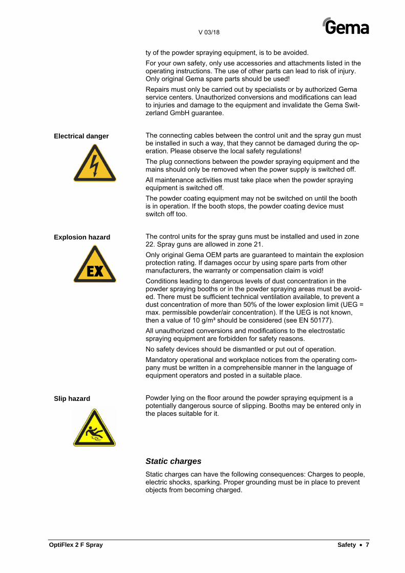
Electrical danger The connecting cables between the control unit and the spray gun must be installed in such a way, that they cannot be damaged during the op-eration. Please observe the local safety regulations!
The plug connections between the powder spraying equipment and the mains should only be removed when the power supply is switched off.
All maintenance activities must take place when the powder spraying equipment is switched off.
The powder coating equipment may not be switched on until the booth is in operation. If the booth stops, the powder coating device must switch off too.
Explosion hazard The control units for the spray guns must be installed and used in zone 22. Spray guns are allowed in zone 21.
Only original Gema OEM parts are guaranteed to maintain the explosion protection rating. If damages occur by using spare parts from other manufacturers, the warranty or compensation claim is void!
Conditions leading to dangerous levels of dust concentration in the powder spraying booths or in the powder spraying areas must be avoid-ed. There must be sufficient technical ventilation available, to prevent a dust concentration of more than 50% of the lower explosion limit (UEG = max. permissible powder/air concentration). If the UEG is not known, then a value of 10 g/m³ should be considered (see EN 50177).
All unauthorized conversions and modifications to the electrostatic spraying equipment are forbidden for safety reasons.
No safety devices should be dismantled or put out of operation.
Mandatory operational and workplace notices from the operating com-pany must be written in a comprehensible manner in the language of equipment operators and posted in a suitable place.
Slip hazard Powder lying on the floor around the powder spraying equipment is a potentially dangerous source of slipping. Booths may be entered only in the places suitable for it.
Static charges Static charges can have the following consequences: Charges to people, electric shocks, sparking. Proper grounding must be in place to prevent objects from becoming charged.
V 03/18
8 • Safety OptiFlex 2 F Spray
Grounding
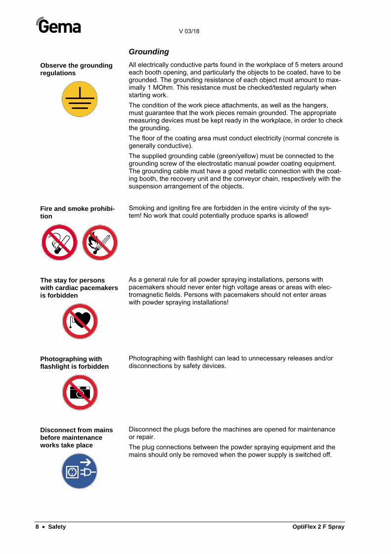
Observe the grounding regulations
All electrically conductive parts found in the workplace of 5 meters around each booth opening, and particularly the objects to be coated, have to be grounded. The grounding resistance of each object must amount to max-imally 1 MOhm. This resistance must be checked/tested regularly when starting work.
The condition of the work piece attachments, as well as the hangers, must guarantee that the work pieces remain grounded. The appropriate measuring devices must be kept ready in the workplace, in order to check the grounding.
The floor of the coating area must conduct electricity (normal concrete is generally conductive).
The supplied grounding cable (green/yellow) must be connected to the grounding screw of the electrostatic manual powder coating equipment. The grounding cable must have a good metallic connection with the coat-ing booth, the recovery unit and the conveyor chain, respectively with the suspension arrangement of the objects.
Fire and smoke prohibi-tion
Smoking and igniting fire are forbidden in the entire vicinity of the sys-tem! No work that could potentially produce sparks is allowed!
The stay for persons with cardiac pacemakers is forbidden
As a general rule for all powder spraying installations, persons with pacemakers should never enter high voltage areas or areas with elec-tromagnetic fields. Persons with pacemakers should not enter areas with powder spraying installations!
Photographing with flashlight is forbidden
Photographing with flashlight can lead to unnecessary releases and/or disconnections by safety devices.
Disconnect from mains before maintenance works take place
Disconnect the plugs before the machines are opened for maintenance or repair.
The plug connections between the powder spraying equipment and the mains should only be removed when the power supply is switched off.
V 03/18
OptiFlex 2 F Spray Safety • 9
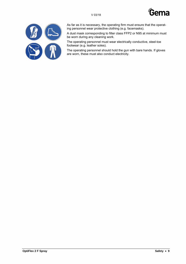
As far as it is necessary, the operating firm must ensure that the operat-ing personnel wear protective clothing (e.g. facemasks).
A dust mask corresponding to filter class FFP2 or N95 at minimum must be worn during any cleaning work.
The operating personnel must wear electrically conductive, steel-toe footwear (e.g. leather soles).
The operating personnel should hold the gun with bare hands. If gloves are worn, these must also conduct electricity.


V 03/18
OptiFlex 2 F Spray Product description • 11
Product description
Field of application The OptiFlex 2 F Spray manual coating equipment (with powder hopper) is exclusively intended for electrostatic coating using organic powders (For more on this please also review chapter "Technical Data").
Any other use is considered non-compliant. The manufacturer is not re-sponsible for any incorrect use and the risks associated with such actions are assumed by the user alone!
For a better understanding of the interrelationships in powder coating, it is recommended that the operating instructions for all other components be read as well, so as to be familiar with their functions too.
Fig. 1
Utilization
This electrostatic manual coating equipment with the OptiSelect GM03 manual powder gun is ideally suited for manual coating of objects.

V 03/18
12 • Product description OptiFlex 2 F Spray
Versions
The manual coating equipment is available in different versions and co-vers a broad application range.
This manual unit is the right solution for coatings that require a constant powder output or high film builds. With a powder output of up to 600 g/min and an extremely high efficiency best coating results are achieved.
Application Precise powder transport
Option I Ia (Extension Kit)
Number of guns 1 1 +1
Number of pumps 1 1 +1
Powder output 1x 50-300 g/min 2x 50-300 g/min
Application Hot coating
Option II IIa (Extension Kit)
Number of guns 1 1 +1
Number of pumps 2 2 +2
Powder output 1x 100-600 g/min 2x 100-600 g/min
V 03/18
OptiFlex 2 F Spray Product description • 13
Reasonably foreseeable misuse
– Operation without the proper training
– Use with insufficient compressed air quality and grounding
– Use in connection with unauthorized coating devices or components
Design and function
Structure
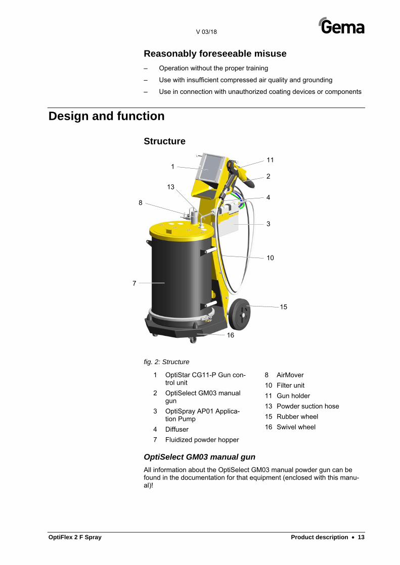
fig. 2: Structure
1 OptiStar CG11-P Gun con-trol unit
2 OptiSelect GM03 manual gun
3 OptiSpray AP01 Applica-tion Pump
4 Diffuser
7 Fluidized powder hopper
8 AirMover
10 Filter unit
11 Gun holder
13 Powder suction hose
15 Rubber wheel
16 Swivel wheel
OptiSelect GM03 manual gun All information about the OptiSelect GM03 manual powder gun can be found in the documentation for that equipment (enclosed with this manu-al)!
3
10
16
15
8
7
11
4
13
1
2
V 03/18
14 • Product description OptiFlex 2 F Spray
OptiStar CG11-P Gun control unit All information about the OptiStar CG11-P Control unit will be found in the corresponding enclosed documentation!
OptiSpray AP01 Application Pump All information about the OptiSpray AP01 application pump will be found in the corresponding enclosed documentation!
Technical Data
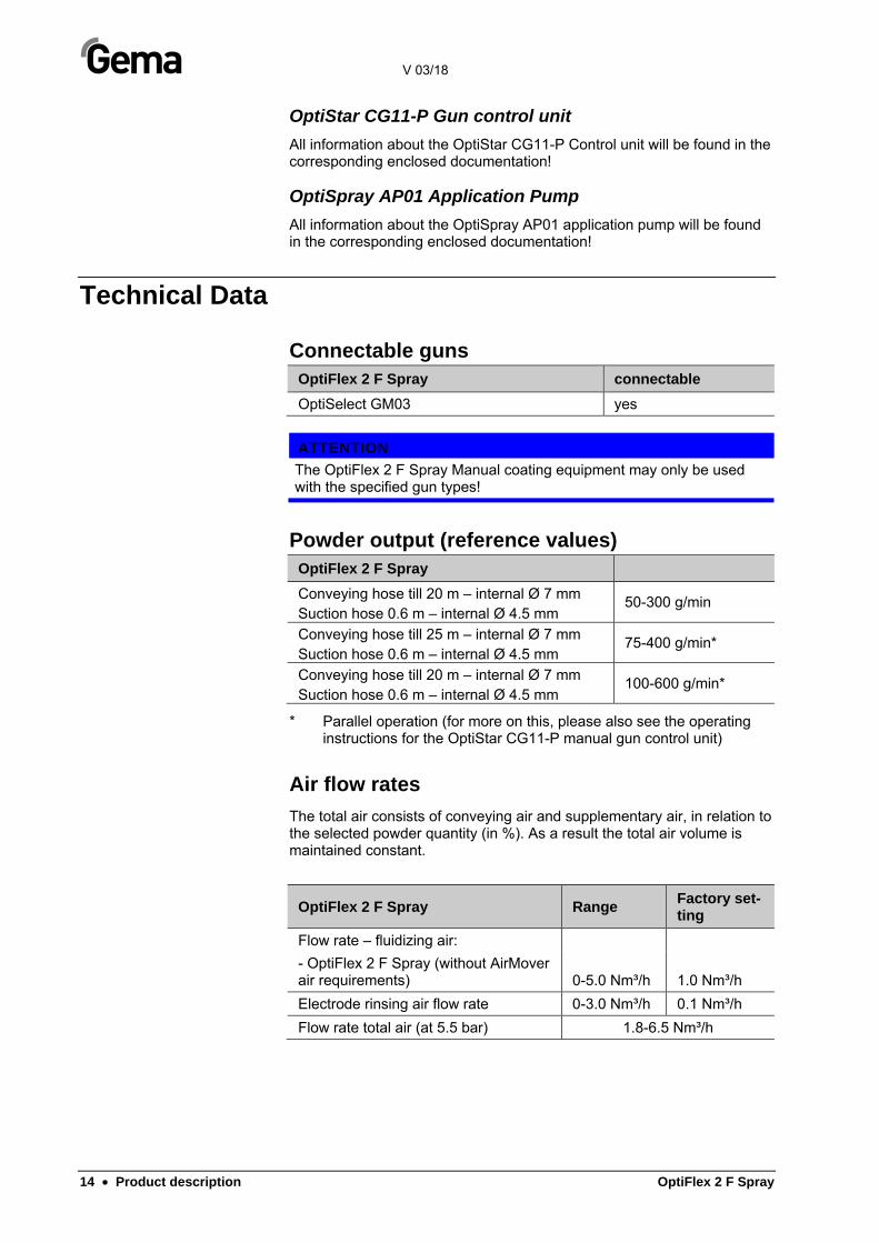
Connectable guns OptiFlex 2 F Spray connectable
OptiSelect GM03 yes
ATTENTION
The OptiFlex 2 F Spray Manual coating equipment may only be used with the specified gun types!
Powder output (reference values) OptiFlex 2 F Spray
Conveying hose till 20 m – internal Ø 7 mm Suction hose 0.6 m – internal Ø 4.5 mm
50-300 g/min
Conveying hose till 25 m – internal Ø 7 mm Suction hose 0.6 m – internal Ø 4.5 mm
75-400 g/min*
Conveying hose till 20 m – internal Ø 7 mm Suction hose 0.6 m – internal Ø 4.5 mm
100-600 g/min*
* Parallel operation (for more on this, please also see the operating instructions for the OptiStar CG11-P manual gun control unit)
Air flow rates
The total air consists of conveying air and supplementary air, in relation to the selected powder quantity (in %). As a result the total air volume is maintained constant.
OptiFlex 2 F Spray Range Factory set-ting
Flow rate – fluidizing air:
- OptiFlex 2 F Spray (without AirMover air requirements) 0-5.0 Nm³/h 1.0 Nm³/h
Electrode rinsing air flow rate 0-3.0 Nm³/h 0.1 Nm³/h
Flow rate total air (at 5.5 bar) 1.8-6.5 Nm³/h
V 03/18
OptiFlex 2 F Spray Product description • 15
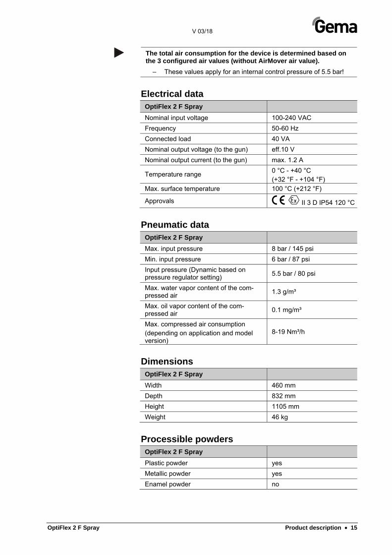
The total air consumption for the device is determined based on the 3 configured air values (without AirMover air value).
– These values apply for an internal control pressure of 5.5 bar!
Electrical data OptiFlex 2 F Spray
Nominal input voltage 100-240 VAC
Frequency 50-60 Hz
Connected load 40 VA
Nominal output voltage (to the gun) eff.10 V
Nominal output current (to the gun) max. 1.2 A
Temperature range 0 °C - +40 °C (+32 °F - +104 °F)
Max. surface temperature 100 °C (+212 °F)
Approvals II 3 D IP54 120 °C
Pneumatic data OptiFlex 2 F Spray
Max. input pressure 8 bar / 145 psi
Min. input pressure 6 bar / 87 psi
Input pressure (Dynamic based on pressure regulator setting)
5.5 bar / 80 psi
Max. water vapor content of the com-pressed air
1.3 g/m³
Max. oil vapor content of the com-pressed air
0.1 mg/m³
Max. compressed air consumption (depending on application and model version)
8-19 Nm³/h
Dimensions OptiFlex 2 F Spray
Width 460 mm
Depth 832 mm
Height 1105 mm
Weight 46 kg
Processible powders OptiFlex 2 F Spray
Plastic powder yes
Metallic powder yes
Enamel powder no

V 03/18
16 • Product description OptiFlex 2 F Spray
Scope of delivery
OptiFlex 2 F Spray
– OptiStar CG11-P Control unit in a metal case with power supply ca-ble
– OptiSpray AP01 Application Pump
– OptiSelect GM03 manual powder gun with gun cable, powder hose, rinsing air hose and standard nozzle set (For more on this, see the operating manual for the OptiSelect GM03 manual powder gun)
– Diffuser
– mobile trolley with a gun/hose support
– Fluidized powder hopper
– Pneumatic hoses for conveying air (red), supplementary air (black), fluidizing air (black) and rinsing air (black)
– Operating manual
– Short description
Typical properties – Characteristics of the functions
Processing of the powder from the fluidized powder container
This manual coating equipment processes powder from the fluidized powder container.
Freely rotating head piece
This manual coating equipment features a freely rotating and lockable head piece for more ergonomic operation and configuration.
fig. 3: Freely rotating head piece
V 03/18
OptiFlex 2 F Spray Start-up • 17
Start-up
Preparation for start-up
Basic conditions
When starting up this manual coating unit, the following general condi-tions impacting the coating results must be taken into consideration:
– Manual coating equipment is set up properly
– Gun control unit correctly connected
– Gun correctly connected
– Corresponding power and compressed air supply available
– Powder preparation and powder quality
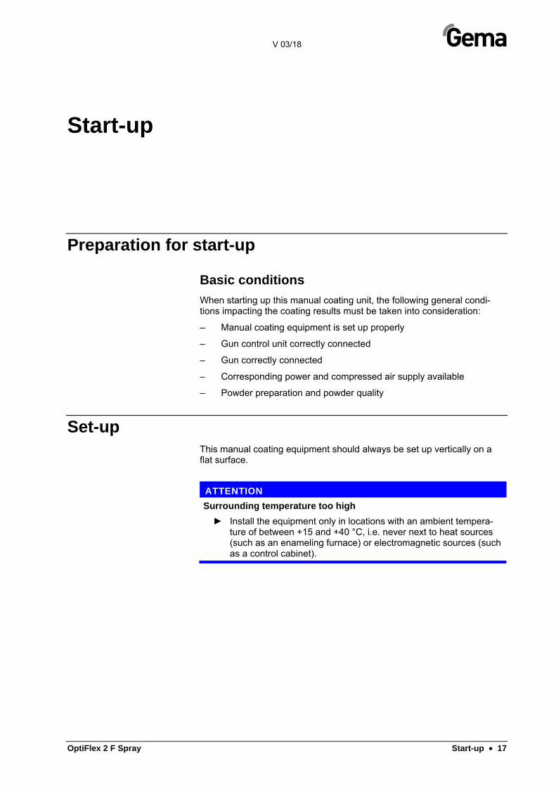
Set-up This manual coating equipment should always be set up vertically on a flat surface.
ATTENTION
Surrounding temperature too high
► Install the equipment only in locations with an ambient tempera-ture of between +15 and +40 °C, i.e. never next to heat sources (such as an enameling furnace) or electromagnetic sources (such as a control cabinet).
V 03/18
18 • Start-up OptiFlex 2 F Spray
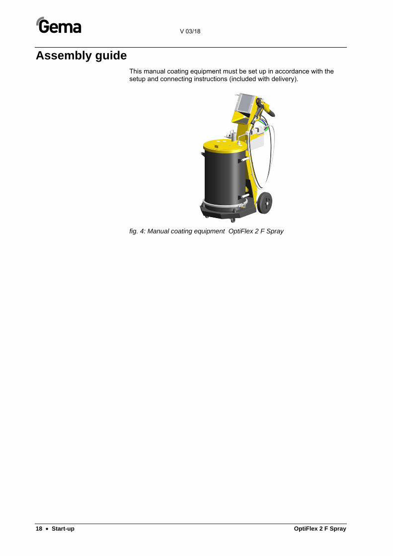
Assembly guide This manual coating equipment must be set up in accordance with the setup and connecting instructions (included with delivery).
fig. 4: Manual coating equipment OptiFlex 2 F Spray

V 03/18
OptiFlex 2 F Spray Start-up • 19
Connection instructions
fig. 5: Connecting guide – overview
1 Spraying air hose
2 Powder hose
3 Gun cable
4 Pinch valve air hose
5 Electrode rinsing air hose
6 Transport air hose
7 Control signal cable
8 Application pump no. 1
8.1 Application pump no. 2
9 Powder hopper
10 Compressed air hose
11 AirMover air hose
12 Fluidizing air hose
The manual coating equipment must be connected in accordance with the setup and connection instructions (Please also review the operating in-structions for the OptiStar CG11-P manual gun control unit).

V 03/18
20 • Start-up OptiFlex 2 F Spray
1. 2.
Use clamp to connect grounding cable to the cabin or the sus-pension arrangement. Check ground connections with Ohm me-ter and ensure 1 MOhm or less.
3. 4.
5. 6.
7. 8.
9. 10.
The compressed air must be free of oil and water!
V 03/18
OptiFlex 2 F Spray Initial start-up • 21
Initial start-up
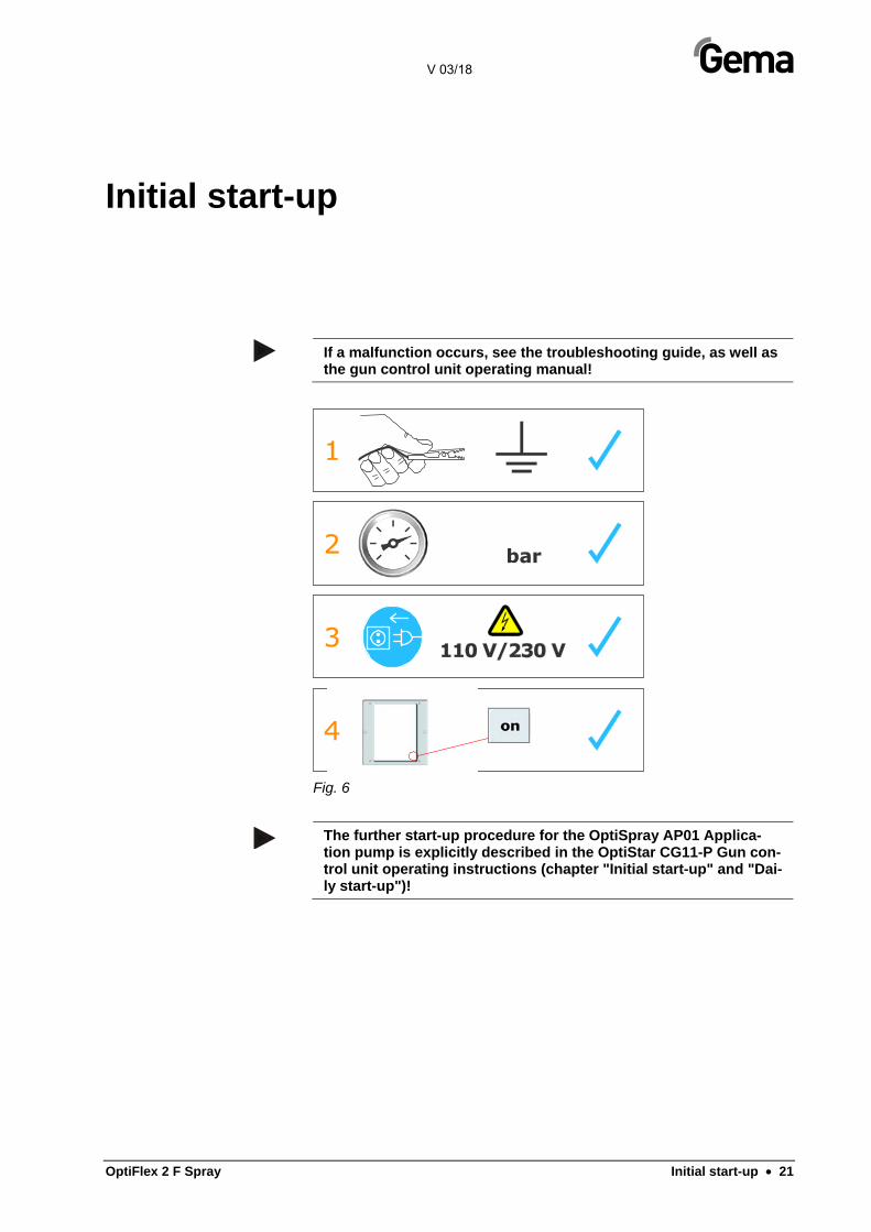
If a malfunction occurs, see the troubleshooting guide, as well as the gun control unit operating manual!
Fig. 6
The further start-up procedure for the OptiSpray AP01 Applica-tion pump is explicitly described in the OptiStar CG11-P Gun con-trol unit operating instructions (chapter "Initial start-up" and "Dai-ly start-up")!

V 03/18
22 • Initial start-up OptiFlex 2 F Spray
Set head piece
1. 2.
3.
Setting the device type
If the control unit is delivered as an integral component of an OptiFlex apparatus, then the system parameter P00 will have been factory preconfigured to the value "5" for optimal use (Ap-plication pump). For more on this, please also see the operating instructions for the OptiStar CG11-P manual gun control unit!
– The gun control unit always starts up to the last configured set-tings.
V 03/18
OptiFlex 2 F Spray Initial start-up • 23
Operation WARNING
Holding the gun incorrectly
During the coating process, the gun can discharge along the body of the coater if not held using its intended handle, which has been grounded.
► Always hold gun only by the handle!
► Do not touch any other parts of the gun!
Coating CAUTION
Large dust formation possible!
If the manual equipment is not being used for coating in conjunc-tion with a sufficiently powerful suction unit, then the stirred-up dust from the coating powder can cause respiratory issues or cause a slippage/falling hazard.
► The manual equipment may only be operated in conjunction with a sufficiently powerful suction unit (such as Gema Classic Open booth).
1. Turn on the gun control unit with the on key. The displays illuminate and the control unit is ready for operation
2. Place powder hopper on the mobile trolley
CAUTION
Large dust formation possible!
When setting the powder hopper onto the mobile trolley of the manual equipment, the hopper/trolley zone represents a threat of crushed toes.
► Wear safety shoes with steel toecaps.
3. Set the ventilation (Airmover)
– Open the ball valve completely
– Calibrate with the throttle valve
4. Fill in powder
– Open the powder hopper filling cover.
– Fill in powder: Fill with maximum 25 kg (50 l) powder or the pow-der must reach to a maximum of 5-10 cm below the handles of the powder hopper, otherwise the fluidized powder can escape from the cover.
– Close the filling cover of the powder hopper again
5. Set coating parameters:
V 03/18
24 • Initial start-up OptiFlex 2 F Spray
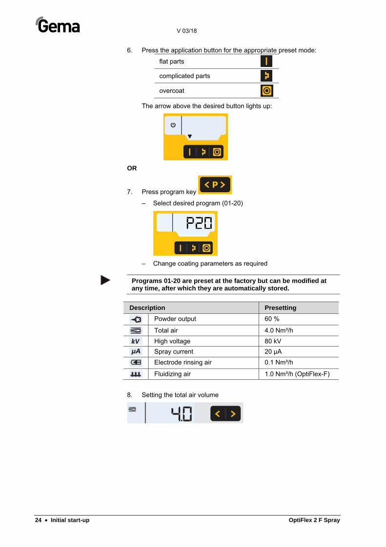
6. Press the application button for the appropriate preset mode:
flat parts
complicated parts
overcoat
The arrow above the desired button lights up:
OR
7. Press program key
– Select desired program (01-20)
– Change coating parameters as required
Programs 01-20 are preset at the factory but can be modified at any time, after which they are automatically stored.
Description Presetting
Powder output 60 %
Total air 4.0 Nm³/h
High voltage 80 kV
Spray current 20 µA
Electrode rinsing air 0.1 Nm³/h
Fluidizing air 1.0 Nm³/h (OptiFlex-F)
8. Setting the total air volume
V 03/18
OptiFlex 2 F Spray Initial start-up • 25
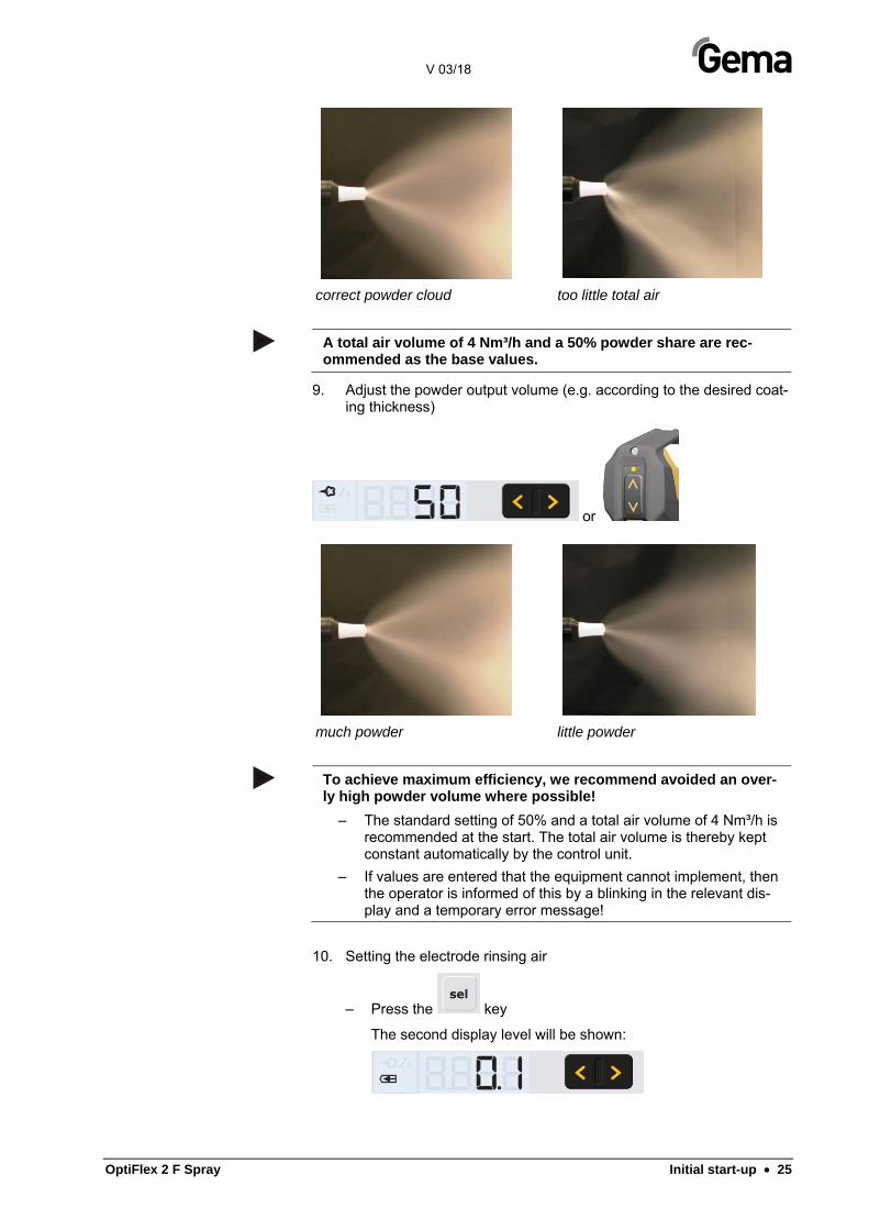
correct powder cloud too little total air
A total air volume of 4 Nm³/h and a 50% powder share are rec-ommended as the base values.
9. Adjust the powder output volume (e.g. according to the desired coat-ing thickness)
or
much powder little powder
To achieve maximum efficiency, we recommend avoided an over-ly high powder volume where possible!
– The standard setting of 50% and a total air volume of 4 Nm³/h is recommended at the start. The total air volume is thereby kept constant automatically by the control unit.
– If values are entered that the equipment cannot implement, then the operator is informed of this by a blinking in the relevant dis-play and a temporary error message!
10. Setting the electrode rinsing air
– Press the key
The second display level will be shown:

V 03/18
26 • Initial start-up OptiFlex 2 F Spray
≈ 0.1 Nm³/h
≈ 0.5 Nm³/h
too much electrode rinsing air
11. Setting the fluidization
– Press the key
The second display level will be shown:
– Check fluidization of the powder in the powder container.
The powder fluidization depends on the powder type, the air hu-midity and the ambient temperature. Fluidizing and vibration start by switching on the control unit.
CAUTION
Large dust formation possible!
If the ventilation has been incorrectly adjusted, then the coating powder can create a dust cloud capable of causing respiratory problems.
► Ensure proper setting of ventilation.
12. Point the gun into the booth (not at the object to be coated), press the gun trigger and visually check the powder output
13. Check whether everything is functioning correctly
14. Coating
15. Adjust the coating parameters as necessary
V 03/18
OptiFlex 2 F Spray Initial start-up • 27
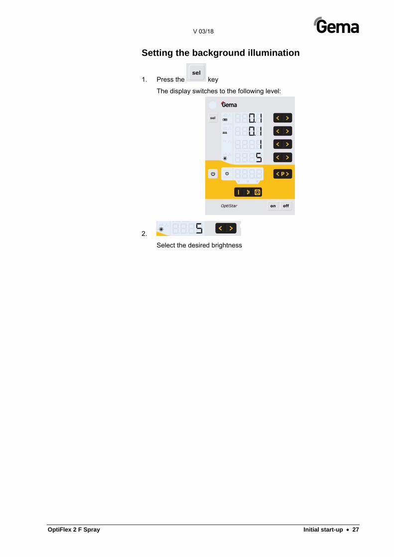
Setting the background illumination
1. Press the key
The display switches to the following level:
2.
Select the desired brightness
V 03/18
28 • Initial start-up OptiFlex 2 F Spray
Color change
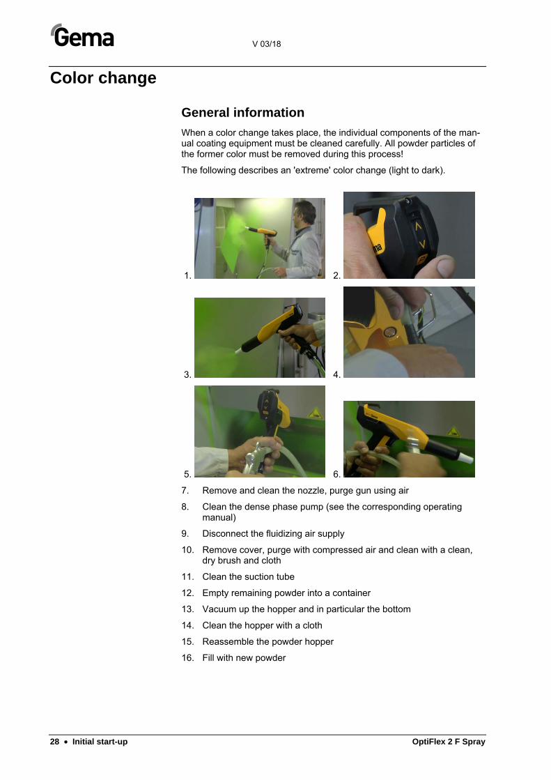
General information
When a color change takes place, the individual components of the man-ual coating equipment must be cleaned carefully. All powder particles of the former color must be removed during this process!
The following describes an 'extreme' color change (light to dark).
1. 2.
3. 4.
5. 6.
7. Remove and clean the nozzle, purge gun using air
8. Clean the dense phase pump (see the corresponding operating manual)
9. Disconnect the fluidizing air supply
10. Remove cover, purge with compressed air and clean with a clean, dry brush and cloth
11. Clean the suction tube
12. Empty remaining powder into a container
13. Vacuum up the hopper and in particular the bottom
14. Clean the hopper with a cloth
15. Reassemble the powder hopper
16. Fill with new powder
V 03/18
OptiFlex 2 F Spray Initial start-up • 29
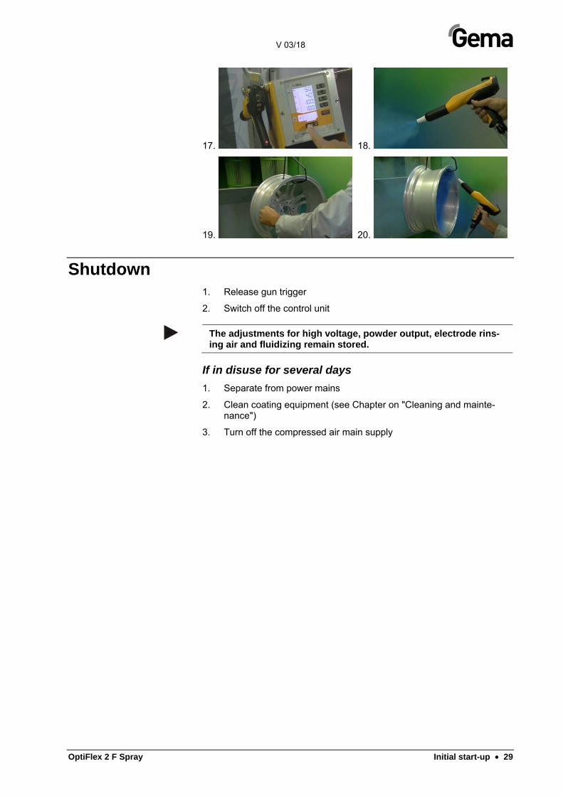
17. 18.
19. 20.
Shutdown 1. Release gun trigger
2. Switch off the control unit
The adjustments for high voltage, powder output, electrode rins-ing air and fluidizing remain stored.
If in disuse for several days 1. Separate from power mains
2. Clean coating equipment (see Chapter on "Cleaning and mainte-nance")
3. Turn off the compressed air main supply

V 03/18
OptiFlex 2 F Spray Cleaning and maintenance • 31
Cleaning and maintenance
Regular, careful cleaning and maintenance extends the service life of the manual coating equipment and ensures long-lasting, uniform coating quality!
– The parts to be replaced during maintenance work are available as spare parts. These parts can be found in the corresponding spare parts list!
Daily maintenance 1. Clean the application pump (see therefore the application pump user
manual)
2. Clean the powder gun (For more on this, please also review the user manual for the OptiSelect GM03 manual powder gun)
3. Clean the powder hose; Please also review the section "Color change"
Weekly maintenance 1. Clean the powder hopper, application pump and powder gun.
2. Check the control unit grounding connections to the coating booth, the suspension devices of the work pieces, or the conveyor chain
If in disuse for several days 1. Separate from power mains
2. Clean the coating equipment
3. Turn off the compressed air main supply
Powder hose rinsing
If longer downtimes take place, the powder hose has to be cleaned.
The procedure is described in the section "Color change".

V 03/18
32 • Cleaning and maintenance OptiFlex 2 F Spray
Cleaning CAUTION
Large dust formation possible!
If no dust mask or one of an insufficient filter class is worn when cleaning the Fresh powder system, then the dust that is stirred up from the coating powder can cause respiratory problems.
► The ventilation system must be turned on for all cleaning work.
► A dust mask corresponding to filter class FFP2 or N95 at mini-mum must be worn during any cleaning work.
Cleaning the powder hopper
ATTENTION
Damage to the fluidizing plate
► Never clean the powder hopper with solvents or water!
1. Disconnect the fluidizing air supply
2. Remove the suction hose
3. Remove the cover, blow out with compressed air and clean with a clean dry brush and cloth
4. Empty remaining powder into a container
5. Vacuum up the hopper and in particular the bottom
6. Clean the hopper with a cloth
7. Reassemble the powder hopper
Refill the powder hopper shortly before reusing!
V 03/18
OptiFlex 2 F Spray Cleaning and maintenance • 33
Cleaning the OptiSelect GM03 manual powder gun
Frequent cleaning of the gun helps to guarantee the coating quality.
Before cleaning the powder gun, switch off the control unit. The compressed air used for cleaning must be free of oil and water!
Daily: 1. Blow off the outside of the gun and wipe, clean etc.
2. Clean the diffuser
Weekly: 3. Remove the powder hose from the connection
4. Remove the diffuser from the gun and clean it
5. Remove the spray nozzle from the gun and clean it
6. Blow out the gun from the connection in flow direction with com-pressed air
7. Clean the integrated gun tube with the provided gun brush
8. Blow through the gun with compressed air again
9. Clean the powder hose
10. Reassemble the gun and connect it
Please also review the user manual for the OptiSelect GM03 man-ual powder gun!

V 03/18
34 • Cleaning and maintenance OptiFlex 2 F Spray
Maintenance and cleaning of the filter unit The filter unit on the manual coating equipment measures and cleans the compressed air. This is where the equipment's main compressed air con-nection is located.
Replacing the filter element
Procedure:
1. Unscrew the filter glass on the filter unit
2. Remove the complete filter element
fig. 7: Replacing the filter element
1. Replace the filter element
2. Clean the filter glass on the inside and install it again
V 03/18
OptiFlex 2 F Spray Troubleshooting • 35
Troubleshooting
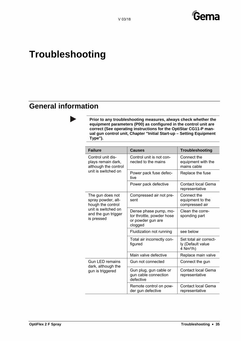
General information
Prior to any troubleshooting measures, always check whether the equipment parameters (P00) as configured in the control unit are correct (See operating instructions for the OptiStar CG11-P man-ual gun control unit, Chapter "Initial Start-up – Setting Equipment Type").
Failure Causes Troubleshooting
Control unit dis-plays remain dark, although the control unit is switched on
Control unit is not con-nected to the mains
Connect the equipment with the mains cable
Power pack fuse defec-tive
Replace the fuse
Power pack defective Contact local Gema representative
The gun does not spray powder, alt-hough the control unit is switched on and the gun trigger is pressed
Compressed air not pre-sent
Connect the equipment to the compressed air
Dense phase pump, mo-tor throttle, powder hose or powder gun are clogged
Clean the corre-sponding part
Fluidization not running see below
Total air incorrectly con-figured
Set total air correct-ly (Default value 4 Nm³/h)
Main valve defective Replace main valve
Gun LED remains dark, although the gun is triggered
Gun not connected Connect the gun
Gun plug, gun cable or gun cable connection defective
Contact local Gema representative
Remote control on pow-der gun defective
Contact local Gema representative

V 03/18
36 • Troubleshooting OptiFlex 2 F Spray
Failure Causes Troubleshooting
Powder does not adhere to object, although the gun is triggered and sprays powder
The objects are improp-erly or insufficiently grounded
Check grounding, reground at better quality
High voltage and current deactivated
Press the selection key (application key)
High voltage cascade defective
Contact local Gema representative
The powder is not fluidized
Compressed air not pre-sent
Connect the equipment to the compressed air
Fluidizing air is set too low on the control unit
Set the fluidizing air correctly
Throttle motor defective Contact local Gema representative
No electrode rinsing air
Rinsing air throttle motor defective
Contact local Gema representative

V 03/18
OptiFlex 2 F Spray Spare parts list • 37
Spare parts list
Ordering spare parts When ordering spare parts for powder coating equipment, please indicate the following specifications:
– Type and serial number of your powder coating equipment
– Order number, quantity and description of each spare part
Example:
– Type OptiFlex 2 F Spray,
Serial number 1234 5678
– Order no. 203 386, 1 piece, Clamp – Ø 18/15 mm
When ordering cable or hose material, the required length must also be given. The spare part numbers of this yard/meter ware is always marked with an *.
The wearing parts are always marked with a #.
All dimensions of plastic hoses are specified with the external and internal diameter:
Example:
Ø 8/6 mm, 8 mm outside diameter (o/d) / 6 mm inside diameter (i/d)
ATTENTION
Use of non-original Gema spare parts
When using the spare parts from other manufacturers the explo-sion protection is no longer guaranteed. If any damage is caused by this use all guarantee claims become invalid!
► Only original Gema spare parts should be used!
V 03/18
38 • Spare parts list OptiFlex 2 F Spray
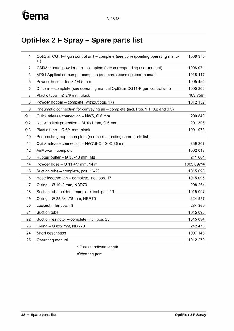
OptiFlex 2 F Spray – Spare parts list
1 OptiStar CG11-P gun control unit – complete (see corresponding operating manu-al)
1009 970
2 GM03 manual powder gun – complete (see corresponding user manual) 1008 071
3 AP01 Application pump – complete (see corresponding user manual) 1015 447
5 Powder hose – dia. 8.1/4.5 mm 1005 454
6 Diffuser – complete (see operating manual OptiStar CG11-P gun control unit) 1005 263
7 Plastic tube – Ø 8/6 mm, black 103 756*
8 Powder hopper – complete (without pos. 17) 1012 132
9 Pneumatic connection for conveying air – complete (incl. Pos. 9.1, 9.2 and 9.3)
9.1 Quick release connection – NW5, Ø 6 mm 200 840
9.2 Nut with kink protection – M10x1 mm, Ø 6 mm 201 308
9.3 Plastic tube – Ø 6/4 mm, black 1001 973
10 Pneumatic group – complete (see corresponding spare parts list)
11 Quick release connection – NW7.8-Ø 10- Ø 26 mm 239 267
12 AirMover – complete 1002 043
13 Rubber buffer – Ø 35x40 mm, M8 211 664
14 Powder hose – Ø 11.4/7 mm, 14 m 1005 097*#
15 Suction tube – complete, pos. 16-23 1015 098
16 Hose feedthrough – complete, incl. pos. 17 1015 095
17 O-ring – Ø 19x2 mm, NBR70 208 264
18 Suction tube holder – complete, incl. pos. 19 1015 097
19 O-ring – Ø 28.3x1.78 mm, NBR70 224 987
20 Locknut – for pos. 18 234 869
21 Suction tube 1015 096
22 Suction restrictor – complete, incl. pos. 23 1015 094
23 O-ring – Ø 8x2 mm, NBR70 242 470
24 Short description 1007 143
25 Operating manual 1012 279
* Please indicate length
#Wearing part

V 03/18
OptiFlex 2 F Spray Spare parts list • 39
OptiFlex 2 F Spray – Spare parts
fig. 8: OptiFlex 2 F Spray – Spare parts
fig. 9: OptiFlex 2 F Spray – Suction tube
V 03/18
40 • Spare parts list OptiFlex 2 F Spray
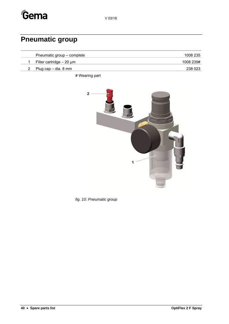
Pneumatic group
Pneumatic group – complete 1008 235
1 Filter cartridge – 20 µm 1008 239#
2 Plug cap – dia. 8 mm 238 023
# Wearing part
fig. 10: Pneumatic group

V 03/18
OptiFlex 2 F Spray Spare parts list • 41