Operating Instructions and Parts Manual RC Series Pumps ...€¦ · Operating Instructions and...
20
Plunger Pumps Form RC-OM 0611 High Performance Pumps Description Plunger Pumps are designed for a wide variety of high pressure washing applications. They are constructed with die-cast bodies and feature a brass head. Internal components include special thick solid ceramic plungers for long life and durability. Precision cast cooling fins are anodized for maximum heat dissipation. Oversized needle bearings on the drive side, and ball on the non-drive side together with the precision supports assure positive alignment and centering in relation to the crankcase. Valve cages of special designed Ultra-Form provide positive seating and extended life. Ball bearings on both sides of solid shaft drive pumps. One-piece connecting rods are special alloy aluminum, oversized for strength and load disbursement. These pumps are designed for, belt drive, or coupling drive systems driven by electric motor or gasoline driven systems, electric motor direct drive systems, and gasoline engine direct drive systems. Please read and save these instructions. Read carefully before attempting to assemble, install, operate or maintain the product described. Protect yourself and others by observing all safety information. Failure to comply with instructions could result in personal injury and/or property damage! Retain instructions for future reference. Operating Instructions and Parts Manual RC Series Pumps RC 1450 rpm N Version - Solid Shaft Model Max GPM Max PSI RC11.17N 2.9 2500 RC13.17N 3.4 2500 RCA 1750 rpm N Version - Solid Shaft Model Max GPM Max PSI RCA2.5G25N 2.5 2500 RCA3G25N 3 2500 RCA3.5G25N 3.5 2500 RCA 1750 rpm E Version - 5/8” Model Max GPM Max PSI RCA2G25E-F8 2 2500 RCA2G25E-F8-SX 2 2500 RCA3G25E-F8 3 2500 RCA3.5G18E-F8 3.5 1800 RCV 3400 rpm E Version - 5/8” Model Max GPM Max PSI RCV2G25D-F8 2 2500 RCV3G25E-F8 3 2500 RC/RCA - N RCA/RCV - F8 RCV - F7 RCV 3400 rpm D Version - 1” Model Max GPM Max PSI RCV2G25D-F7 2 2500 RCV2.5G25D-F7 2.5 2500 RCV2.5G25D-F7-SX 2.5 2500 RCV2.5G27D-F7 2.5 2700 3 2500 RCV3G25D-F7 RCV3G27D-F7 RCV3.5G25D-F7 3.5 2700 3 2500
-
Upload
vuongxuyen -
Category
Documents
-
view
217 -
download
2
Transcript of Operating Instructions and Parts Manual RC Series Pumps ...€¦ · Operating Instructions and...

Plunger Pumps Operating Instructions and Parts Manual RC Series Pumps
First Choice When Quality Matters
NORTHAMERICA
Form RC-OM 0611 High Performance Pumps
DescriptionPlunger Pumps are designed for a wide variety of high pressure washing applications. They are constructed with die-cast bodies and feature a brass head. Internal components include special thick solid ceramic plungers for long life and durability. Precision cast cooling fins are anodized for maximum heat dissipation. Oversized needle bearings on the drive side, and ball on the non-drive side together with the precision supports assure positive alignment and centering in relation to the crankcase. Valve cages of special designed Ultra-Form provide positive seating and extended life. Ball bearings on both sides of solid shaft drive pumps. One-piece connecting rods are special alloy aluminum, oversized for strength and load disbursement. These pumps are designed for, belt drive, or coupling drive systems driven by electric motor or gasoline driven systems, electric motor direct drive systems, and gasoline engine direct drive systems.
Please read and save these instructions. Read carefully before attempting to assemble, install, operate or maintain the product described. Protect yourself and others by observing all safety information. Failure to comply with instructions could result in personal injury and/or property damage! Retain instructions for future reference.
Operating Instructions and Parts Manual RC Series Pumps
RC 1450 rpm N Version - Solid ShaftModel Max GPM Max PSI RC11.17N 2.9 2500 RC13.17N 3.4 2500
RCA 1750 rpm N Version - Solid Shaft Model Max GPM Max PSI RCA2.5G25N 2.5 2500 RCA3G25N 3 2500 RCA3.5G25N 3.5 2500
RCA 1750 rpm E Version - 5/8”Model Max GPM Max PSI RCA2G25E-F8 2 2500 RCA2G25E-F8-SX 2 2500 RCA3G25E-F8 3 2500 RCA3.5G18E-F8 3.5 1800
RCV 3400 rpm E Version - 5/8” Model Max GPM Max PSI RCV2G25D-F8 2 2500 RCV3G25E-F8 3 2500
RC/RCA - N
RCA/RCV - F8
RCV - F7
RCV 3400 rpm D Version - 1”Model Max GPM Max PSI RCV2G25D-F7 2 2500 RCV2.5G25D-F7 2.5 2500 RCV2.5G25D-F7-SX 2.5 2500 RCV2.5G27D-F7 2.5 2700
3 2500RCV3G25D-F7RCV3G27D-F7 RCV3.5G25D-F7 3.5
27003 2500

First Choice When Quality Matters
NORTHAMERICA
Plunger Pumps Operating Instructions and Parts Manual RC Series Pumps
183,5125,5
92,5
4,5
5328
58200
55 7155 8 40
4881 119
62925,721
22
5,22 853, 4213, 641
21
° 09
45°
3068
M8 N°4 fori
Ø 75Ø90
0
- 0.
36h9 h7
8
0-
0.21
Ø 2
4
”8/3 G T
UO
”2/1 G
NI412
12
75
0- 0.54 h
8
RC/RCA N version Solid shaft pump / ø 24 mm
55 54”8/3 G T
UO
”2/1 G
NI
12
12
75
81 101
182
39 15
140
140
195,5125,5 70
Ø149,2±0,1
R 82,5
18,2+0,1 0
4,8
+0,0
4- 0
,01
Ø15
,9+0
,018
0
4,5
6292
Ø10 n°4 fori
45° 45°
RCA/RCV E version + F8Hollow shaft pump ø 5/8”
183,584
4,5 28
6292
21
68
84
853,421
125,5 58
4,8+
0,04
-0,0
1
Ø92±0,1R4,2
5 21,4+0,1 -0
”8/3 G T
UO
”2/1 G
NI
75
81 110
191
39 15
55
12
12
63+0,5 0
63+
0,5
0
RCV D version + F7Hollow shaft pump ø 1”

Plunger Pumps Operating Instructions and Parts Manual RC Series Pumps
First Choice When Quality Matters
NORTHAMERICA
FormulasNozzles:Impact Force (lbs.) = .0526 x GPM x √PSI
Nozzle # = GPM x 4000√ PSI
GPM= Nozzle # x PSI √4000
PSI = (GPM/Nozzle #)2 x 4000Horse Power:GPM x PSI = Hydraulic HP 1714
GPM x PSI = EBHP 1457
EBHP x 1457 = GPM PSI
EBHP x 1457 = PSI GPM
HP loss due to altitude = 3% per 1000 FT above sea levelPump Speed and Flow:Rated GPM = Desired GPMRated RPM Desired RPM
Motor Pulley Ø = Pump Pulley Ø Pump RPM Motor RPM
ConversionsGallons x 3.785412 = LitersGallons x 128 = Oz.PSI x .06896 = BarBar x 14.5038 = PSI1 inches = 25.4 millimetersLiters x .2642 = Gallons (US)Ft. Lbs. x 1.356 = Newton MetersInch Lbs. x .11298 = Newton MetersNewton Meters x .737562 = Ft. Lbs. (force)Newton Meters x 8.85 = In. Lbs. (force)Temperature = 1.8(C° + 17.78) = F°,.555(F° - 32) = C°1 U.S. Gallon of freshwater = 8.33 lbs.1 PSI = 2.31 feet of water1 PSI = 2.04 inches of mercury1 Foot of water = .433 PSI1 Foot of water = .885 inches of mercury1 Meter of water = 3.28 feet of waterKilograms x 2.2 = Lbs.
General Safety Information
WARNINGSGasoline Drive Pumps
The pump is designed to pump non-flammable or non-explosive fluids. These pumps are intended to pump
clean filtered water only.
Do not operate in or around an explosive environment.
Always wear safety glasses or goggles and appropriate
clothing.
Do not alter the pump from the manufacturers design.
Do not allow children to operate the pump.
Never point the high-pressure discharge at a person, any part of the body or animals.
Do not operate gasoline engines in a confined area; always have adequate ventilation.
Do not exceed the pump specifications in speed or pressure.

First Choice When Quality Matters
NORTHAMERICA
Plunger Pumps Operating Instructions and Parts Manual RC Series Pumps
General Safety Information (continued)
Maximum water temperature is 140°F.
All positive displacement plunger pumps must have a safety relief valve installed on the discharge side of the pump, this valve could be either an unloader or regulator and must be of adequate flow and pressure for the pump.
Adequate protective guards must cover all moving parts. Perform routine maintenance on the pump and components.
Use only components that are rated for the flow and pressure of the pump, this would include hose, fittings, safety valves, spray guns etc.
Electric Drive PumpsYour power supply must conform to the
system requirements.
The motor must be grounded. Use GFCI plugs and receivers.
Do not handle the pump/motor with wet hands.
Only use power cords that are in good condition.
Never pull the unit by the power cord.
Never spray or clean the unit with water
Failure to follow these warnings may result in personal injury or damage to property.
InstallationDIRECT DRIVE PUMPS
1. Install the shaftkey into the keywayand apply a lightcoating of anti-seizeon the engine shaft.(See Figure 7 & 8)
2. Align the two key waysand push the pumpcompletely onto theengine.
3. Install all four (4) bolts and tightenevenly.
4. Remove the redshipping oil cap andinstall the blackcrankcase vent cap.(See Figure 9)
5. Install theappropriate unloader valve and other accessories.
6. Install the appropriate water inletand discharge fittings.
7. Connect the water supply hose andhigh-pressure discharge hose/spraygun.
8. Turn on the water supply.
9. Open the spray gun to purge thesystem of any air.
10. Start the engine.
11. Adjust the engine speed andunloader valve.
Figure 9
Figure 7
Figure 8

Plunger Pumps Operating Instructions and Parts Manual RC Series Pumps
First Choice When Quality Matters
NORTHAMERICA
BELT DRIVE SYSTEMS
1. Mount the pumpsecurely to thebase plate. (SeeFigure 10) Fornew installation a mounting rail kit isrequired, refer to parts breakdown.
2. Install the pump pulley on thecrankshaft. It should be as far ontothe shaft as possible.
3. Align the pulleys so theyare in line. (See Figure11)
4. Use a belt tensiongauge to assure propertension (too muchtension can causebearing failure ordamage the belts aswell as cause otherproblems). (SeeFigure 12)
5. Installationcomplete.
MaintenanceSERVICING THE VALVES
The inlet and discharge valves in this series pumps are all the same. The valves are located under the six 21mm hex plugs. The inlet valves are located on the lower row and the discharge valves are located on the top row of the pump head.
Tools required: 21mm socket, ratchet, needle nose pliers, mechanics pick and torque wrench.
VALVE REMOVAL
1. Remove the valve cap.(See Figure 13)
2. Inspect the valve capO-ring for any damage,replace if necessary.
3. Use the needle nosepliers to remove thevalve. (See Figure 14)
4. Use a small probeto move the poppetup and down toassure that the valve is functioning properly and that nodebris is stuck in the valve.
5. Inspect the valve seat o-ring for anydamage, replace if necessary.
VALVE ASSEMBLY
1. Insert the valve assemblysquarely into the portpush it squarely intoposition with a small deepwell socket and extensionuntil fully seated. (SeeFigure 15)
2. Install the valve capand torque to theproper specification.(See Figure 16)(See Table D or partsbreakdown)
SERVICING THE PACKINGS/SEALS
To access the water seals for inspection or replacement, you will first need to remove the head of the pump.
Tools required: 5mm hex socket, ratchet, (2) long screwdrivers, reversible pliers, mechanics pick and torque wrench.
Installation (continued)
Figure 10
Figure 12
Figure 11
Figure 13
Figure 14
Figure 16
Figure 15

First Choice When Quality Matters
NORTHAMERICA
Plunger Pumps Operating Instructions and Parts Manual RC Series Pumps
DISASSEMBLY
1. First remove the eight 5mm headbolts.
2. Place the screwdrivers as shownbetween the head and crankcase ofthe pump, liftingone up and theother down. Thehead should startto lift off of theplungers. (See Figure 17)
3. When you remove the head youmay notice that some of thewater seals have stayed on theplungers and some inthe head. To removethe seals from theplungers simple turn theassemblies and pull off.(See Figure 18)
4. If the seal assemblies are in thehead use the reversible pliers tograb the seal retainer onthe outside ring, twistthe retainer in eitherdirection (this is done tofree the retainer O-ringwhich is stuck to themanifold) and lift out.(See Figure 19)
5. With your finger pullout the brass intermediate guidering.
6. With your finger pullthe high-pressure sealand head ring out ofthe head. (See Figure20)
7. The low-pressure seal is located inthe brass seal retainer. Using themechanics pick, go inbetween the seal andretainer and pull theseal straight out. (SeeFigure 21)
8. Remove the sealretainer O-ring with themechanics pick. (See Figure 22)
ASSEMBLY
1. Install the plastic head ringinto the head (the flat sideis on the bottom).
2. Install the high-pressure seal. Placethe seal so the open “V” portion istoward the head ring. You need toplace the seal at anangle and pull andpush to work the sealinto position withyour fingers (do notuse any tools you maydamage the seal).Make sure the seal is totally seated againstthe head ring. (See Figure 23)
3. Place the brass intermediate ringsquarely over the high-pressure seal
4. Install the low-pressure seals into therear piston guide. Make sure thebrown scrapper ring is in place on thebackside of the seal (NOTE: Care mustbe taken so the ring does not fall outduring assembly). Thescrapper side of the sealgoes into the pistonguide. Push the sealdown until fully seated.You should be lookingat the open side of theseal. (See Figure 24)
Service Pumps (continued)
Figure 17
Figure 18
Figure 19
Figure 22
Figure 23
Figure 20
Figure 21
Figure 24

Plunger Pumps Operating Instructions and Parts Manual RC Series Pumps
First Choice When Quality Matters
NORTHAMERICA
5. Install the retainer O-ring.
6. Squarely seatthe retainerinto the headand push witheven pressureuntil it snaps intoposition. (SeeFigure 25)
SERVICING THE PLUNGERS
If the plungers are not damaged they do not need any servicing.
Tools required: 13mm socket, ratchet, mechanics pick, taper blade gasket scraper, thread sealant and torque wrench.
NOTE: Be very careful when working with the plungers, they are made from ceramic which is brittle and can be damaged.
Any time you remove a plunger it is recommended you replace the slinger washer, O-ring and top plunger washer. The washers are a cushion for the ceramic plunger and compress when first used and the O-ring will take a set to create a seal and usually will not spring back to its original shape. By not replacing these parts you run the risk of breaking a plunger or having a water leak.
DISASSEMBLY
1. Remove the plungerretainer nut. (See Figure26)
2. Insert the gasket scraperbetween the copperwasher and plunger toremove the washer. (SeeFigure 27)
3. Twist and pull theplunger off the plungerrod. (See Figure 28)
4. Remove the plungerrod O-ring seal withthe mechanics pick.
5. Remove the brass slinger. At thispoint clean any thread locker thatis left on the plunger rod andretaining nut threads.
ASSEMBLY
1. Install the brass slinger washer.
2. Install the plunger rod O-ring.Place a light film of oil on theO-ring.
3. Install the plunger bypushing straight downand twisting slightly ineither direction. Makesure you fully seat theplunger. (See Figure29)
4. Install the small copperwasher on top of theplunger and place a smallquantity of thread sealantin the thread. Install theplunger nut and tighten tothe required torque. (SeeFigure 30) (See Table D orparts breakdown)
PUMP HEAD TO DRIVE END INSTALLATION
1. Turn the crankshaft toalign the plungers asshown. (See Figure 31)
Service Pumps (continued)
Figure 25
Figure 26
Figure 27
Figure 29
Figure 30
Figure 31
Figure 28

First Choice When Quality Matters
NORTHAMERICA
Plunger Pumps Operating Instructions and Parts Manual RC Series Pumps
2. Place the head evenlyonto the plungers andpush it until it makescontact with the driveend of the pump. (SeeFigure 32)
3. Torque the head bolt asshown in the tighteningsequence diagram. (SeeFigure 33 & 34) (See Table Dor parts breakdown)
OIL CHANGE
Change oil after first 50 hours of use. Then every 500 hours. Refer to parts breakdown for oil type.
WINTER OR LONG TIME STORAGE
1. Drain all of the water out of thepump.
2. Run a 50% solution of a RV ornon-toxic/biodegradable antifreezethrough the pump.
3. Flush the pump with fresh waterbefore the next use.
4. In freezing conditions failure todo this may cause internal pumpdamage.
5. For long periods of storage innon-freezing areas the solutionwill keep the seals and O-ringslubricated.
Service Pumps (continued)
Figure 33
Figure 32
Figure 34

Plunger Pumps Operating Instructions and Parts Manual RC Series Pumps
First Choice When Quality Matters
NORTHAMERICA
Notes
First Choice When Quality Matters
NORTHAMERICA
Plunger Pumps Operating Instructions and Parts Manual RC Series Pumps
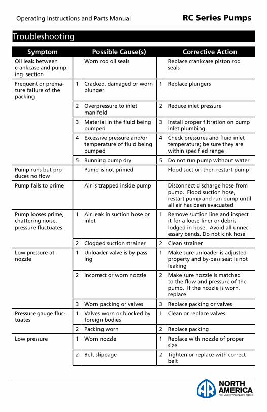
Symptom Possible Cause(s) Corrective ActionOil leak between crankcase and pump-ing section
Worn rod oil seals Replace crankcase piston rod seals
Frequent or prema-ture failure of the packing
1 Cracked, damaged or worn plunger
1 Replace plungers
2 Overpressure to inlet manifold
2 Reduce inlet pressure
3 Material in the fluid being pumped
3 Install proper filtration on pump inlet plumbing
4 Excessive pressure and/or temperature of fluid being pumped
4 Check pressures and fluid inlet temperature; be sure they are within specified range
5 Running pump dry 5 Do not run pump without water
Pump runs but pro-duces no flow
Pump is not primed Flood suction then restart pump
Pump fails to prime Air is trapped inside pump Disconnect discharge hose from pump. Flood suction hose, restart pump and run pump until all air has been evacuated
Pump looses prime, chattering noise, pressure fluctuates
1 Air leak in suction hose or inlet
1 Remove suction line and inspect it for a loose liner or debris lodged in hose. Avoid all unnec-essary bends. Do not kink hose
2 Clogged suction strainer 2 Clean strainer
Low pressure at nozzle
1 Unloader valve is by-pass-ing
1 Make sure unloader is adjusted property and by-pass seat is not leaking
2 Incorrect or worn nozzle 2 Make sure nozzle is matched to the flow and pressure of the pump. If the nozzle is worn, replace
3 Worn packing or valves 3 Replace packing or valves
Pressure gauge fluc-tuates
1 Valves worn or blocked by foreign bodies
1 Clean or replace valves
2 Packing worn 2 Replace packing
Low pressure 1 Worn nozzle 1 Replace with nozzle of proper size
2 Belt slippage 2 Tighten or replace with correct belt
Troubleshooting

Plunger Pumps Operating Instructions and Parts Manual RC Series Pumps
First Choice When Quality Matters
NORTHAMERICA
Symptom Possible Cause(s) Corrective ActionLow pressure (cont.) 3 Air leak in inlet plumbing 3 Disassemble, reseal and reas-
semble
4 Relief valve stuck, partially plugged or improperly adjusted valve seat worn
4 Clean and adjust relief valve; check for worn or dirty valve seats
5 Worn packing. Abrasive in pumped in cavitation. Inadequate water
5 Install proper filter suction at inlet manifold must be limited to lifting less than 20 feet of water or 8.5 psi vacuum
6 Worn inlet, discharge valve blocked or dirty
6 Replace inlet and discharge valve
Pump runs extremely rough, pressure very low
1 Inlet restrictions and/or air leaks.
1 Clean out foreign material
2 Stuck inlet or discharge valve
2 Replace worn valves
Water leakage from under manifold
Worn packing or cracked plunger
Install new packing or plunger
Slight leak, oil leak-ing in the area of crankshaft
1 Worn crankshaft seal or improperly installed oil seal o-ring
1 Remove oil seal retainer and replace damaged 0-ring and/or seals
2 Bad bearing 2 Replace bearing
Excessive play in the end of the crankshaft pulley
Worn main bearing from excessive tension on drive belt
Replace crankcase bearing and/or tension drive belt
Water in crankcase 1 Humid air condensing into water inside the crankcase
1 Change oil intervals
2 Worn packing and/or cracked plunger
2 Replace packing. Replace plunger
Loud knocking noise in pump
1 Cavitation or sucking air 1 Check water supply is turned on
2 Pulley loose on crankshaft 2 Check key and tighten set screw
3 Broken or worn bearing 3 Replace bearing
Troubleshooting (cont.)

First Choice When Quality Matters
NORTHAMERICA
Plunger Pumps Operating Instructions and Parts Manual RC Series Pumps
RC 1450 rpm
Repair Kits
3(6)
30(3)
12(3)
Oil SealsKit 42468
O-RingsKit 42470
2(6)
7(1)
9(1)
16(3)
37(1)
39(1)
22(1)
33(1)
Water SealsKit 42469
32(3)ValvesKit 2186
45
PistonsKit 42467 Support Ring
Kit 2745
11(3)16(3)
14(3)15(3)
4 5 6 7 8
12
11
1920
2122
2324
25
1213
1416
2829
30
34
310
27
9
1
23
1517 18
26
3132
33
3536 37
3940
41
38
4244
43
2045
4647
48
3(6)
30(3)
12(3)
Oil SealsKit 42468
O-RingsKit 42470
2(6)
7(1)
9(1)
16(3)
37(1)
39(1)
22(1)
33(1)
Water SealsKit 42469
32(3)ValvesKit 2186
45
PistonsKit 42467 Support Ring
Kit 2745
11(3)16(3)
14(3)15(3)

Plunger Pumps Operating Instructions and Parts Manual RC Series Pumps
First Choice When Quality Matters
NORTHAMERICA
Pos. Code Description Qty. Pos. Code Description Qty.
1 3200110 Plug (216 in/lbs) 6 2 120690 O-Ring 6
3 2769050 Complete valve (92 in/lbs) 6 4 800410 Screw 8 5 1381550 Washer 8 6 3200020 Head 1 7 180101 O-Ring 1 8 820361 Plug (354 in/lbs) 1 9 740290 O-Ring 1 10 1980740 Plug (221 in/lbs) 1 11 1780140 Ring 3 12 1780720 Gasket 3 13 3200130 Piston guide 3 14 3200142 Gasket 3 15 3200260 Ring 3 16 770260 O-Ring 3 17 3200120 Piston guide 3 18 3200010 Pump body 1 19 1780490 Bearing 1 20 1260790 Snap ring 2 21 1780550 Snap ring 1 22 395081 O-Ring 1 23 3200090 Disc 1 24 3200080 Oil indicator 1 25 3200070 Cover 1 26 1200430 Screw (92 in/lbs) 8 27 880130 Oil cap 1 28 1260110 Nut (106 in/lbs) 3 29 1260100 Washer 3 30 1260210 Piston guide 3 31 1260091 Spacer 3 32 1260460 Seal 3 33 480480 O-Ring 3 34 3200060 Piston guide 3 35 3200040 Conrod 3 36 1780050 Conrod pin 3 37 2760280 O-Ring 1 38 3200030 Rear cover 1
39 820510 O-Ring 1 40 880581 Plug 1 41 3200220 Screw 4 44 3200290 Crankshaft m 1 44 3200270 Crankshaft r 1 42 3200330 Key 1 43 2760350 Bearing 1 45 1260750 Seal 1 46 320210 Base 2 47 1322640 Washer 4 48 850250 Screw 4
AR64516 Oil 2 Oil CapaCity - 9.81 Oz
LegendFor m For rRC11.17 RC13.17
First Choice When Quality Matters
NORTHAMERICA
Plunger Pumps Operating Instructions and Parts Manual RC Series Pumps
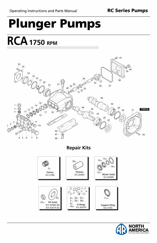
RCA 1750 rpm
Repair Kits
3(6)
30(3)
12(3) Oil SealsKit 42468 (N)Kit 42474 (E)
O-RingsKit 42470
2(6)
7(1)
9(1)
16(3)
37(1)
39(1)
22(1)
33(1)
Water SealsKit 42469
32(3)ValvesKit 2186
45
PistonsKit 42467 Support Ring
Kit 2745
11(3)16(3)
14(3)15(3)
4 5 6 7 8
12
11
1920
2122
2324
25
1213
1416
2829
30
34
310
27
9
1
23
1517 18
26
3132
33
3536 37
3940
41
38
4244
43
2045
4647
48
43
20
44
45 77 TYPE F8
78
3(6)
30(3)
12(3) Oil SealsKit 42468 (N)Kit 42474 (E)
O-RingsKit 42470
2(6)
7(1)
9(1)
16(3)
37(1)
39(1)
22(1)
33(1)
Water SealsKit 42469
32(3)ValvesKit 2186
45
PistonsKit 42467 Support Ring
Kit 2745
11(3)16(3)
14(3)15(3)

Plunger Pumps Operating Instructions and Parts Manual RC Series Pumps
First Choice When Quality Matters
NORTHAMERICA
Pos. Code Description Qty. Pos. Code Description Qty.
1 3200110 Plug (216 in/lbs) 6 2 120690 O-Ring 6
3 2769050 Complete valve (92 in/lbs) 6 4 800410 Screw 8 5 1381550 Washer 8 6 3200020 Head 1 7 180101 O-Ring 1 8 820361 Plug (354 in/lbs) 1 9 740290 O-Ring 1 10 1980740 Plug (221 in/lbs) 1 11 1780140 Ring 3 12 1780720 Gasket 3 13 3200130 Piston guide 3 14 3200142 Gasket 3 15 3200260 Ring 3 16 770260 O-Ring 3 17 3200120 Piston guide 3 18 3200010 Pump body 1 19 1780490 Bearing 1 20 1260790 Snap ring 2 21 1780550 Snap ring 1 22 395081 O-Ring 1 23 3200090 Disc 1 24 3200080 Oil indicator 1 25 3200070 Cover 1 26 1200430 Screw (92 in/lbs) 8 27 880130 Oil cap 1 28 1260110 Nut (106 in/lbs) 3 29 1260100 Washer 3 30 1260210 Piston guide 3 31 1260091 Spacer 3 32 1260460 Seal 3 33 480480 O-Ring 3 34 3200060 Piston guide 3 35 3200040 Conrod 3 36 1780050 Conrod pin 3 37 2760280 O-Ring 1 38 3200030 Rear cover 1
39 820510 O-Ring 1 40 880581 Plug 1 41 3200220 Screw 4 44 3200330 Crankshaft - Solid Shaft m1 44 3200310 Crankshaft - Solid Shaft l1 44 3200290 Crankshaft - Solid Shaft u1 44 3201190 Crankshaft - Hollow Shaft n1 44 3200180 Crankshaft - Hollow Shaft ³1 44 3200830 Crankshaft - Hollow Shaft «1 42 3200330 Key 1 43 2760350 Bearing 1 45 1260750 Seal 1 45 480671 Seal 1 46 320210 Base 2 47 1322640 Washer 4 48 850250 Screw 4 77 1584 Flange (F8) 1 78 1200430 Screw 4
AR64516 Oil 2 Oil CapaCity - 9.81 Oz
Legend
For m For l For u RCA25G25 RCA3G25 RCA35G25
For n For ³ For « RCA2G25 RCA3G25 RCA35G16

First Choice When Quality Matters
NORTHAMERICA
Plunger Pumps Operating Instructions and Parts Manual RC Series Pumps
RCV 3400 rpm
Repair Kits
3(6)
30(3)
12(3)Oil SealsKit 42474
O-RingsKit 42470
2(6)
7(1)
9(1)
16(3)
37(1)
39(1)
22(1)
33(1)
Water SealsKit 42476
32(3)ValvesKit 2186
45
PistonsKit 42467 Support Ring
Kit 2745
11(3)16(3)
14(3)15(3)
4 5 6 7 8
12
11
1920
2122
2324
25
1213
1416
2829
30
34
310
27
9
1
23
1517 18
26
3132
33
3536 37
3940
41
38
43
20
44
45 77
4647
48 TYPE F8
78
43
20
44
4577
TYPE F7
78
3(6)
30(3)
12(3)Oil SealsKit 42474
O-RingsKit 42470
2(6)
7(1)
9(1)
16(3)
37(1)
39(1)
22(1)
33(1)
Water SealsKit 42476
32(3)ValvesKit 2186
45
PistonsKit 42467 Support Ring
Kit 2745
11(3)16(3)
14(3)15(3)

Plunger Pumps Operating Instructions and Parts Manual RC Series Pumps
First Choice When Quality Matters
NORTHAMERICA
Legend
Pos. Code Description Qty. Pos. Code Description Qty.
1 3200110 Plug (216 in/lbs) 6 2 120690 O-Ring 6
3 2769050 Complete valve (92 in/lbs) 6 4 800410 Screw 8 5 1381550 Washer 8 6 3200020 Head 1 7 180101 O-Ring 1 8 820361 Plug (354 in/lbs) 1 9 740290 O-Ring 1 10 1980740 Plug (221 in/lbs) 1 11 1780140 Ring 3 12 1780720 Gasket 3 13 3200130 Piston guide 3 14 3200142 Gasket 3 15 3200260 Ring 3 16 770260 O-Ring 3 17 3200120 Piston guide 3 18 3200010 Pump body 1 19 1780490 Bearing 1 20 1260790 Snap ring 2 21 1780550 Snap ring 1 22 395081 O-Ring 1 23 3200090 Disc 1 24 3200080 Oil indicator 1 25 3200070 Cover 1 26 1200430 Screw (92 in/lbs) 8 27 880130 Oil cap 1 28 1260110 Nut (106 in/lbs) 3 29 1260100 Washer 3 30 1260210 Piston guide 3 31 1260091 Spacer 3 32 1260460 Seal 3 33 480480 O-Ring 3 34 3200060 Piston guide 3 35 3200040 Conrod 3 36 1780050 Conrod pin 3 37 2760280 O-Ring 1 38 3200030 Rear cover 1
39 820510 O-Ring 1 40 880581 Plug 1 41 3200220 Screw 4 44 3201200 Crankshaft - Solid Shaft m1 44 3200860 Crankshaft - Solid Shaft l1 44 3201180 Crankshaft - Solid Shaft u1 44 3201170 Crankshaft - Hollow Shaft n1 44 3200350 Crankshaft - Hollow Shaft ³1 44 3200340 Crankshaft - Hollow Shaft «1 42 3200330 Key 1 43 2760350 Bearing 1 45 480671 Seal 1 46 320210 Base 2 47 1322640 Washer 4 48 850250 Screw 4 77 1579 Flange (F7) 1 77 1584 Flange (F8) 1 78 1200430 Screw 4
AR64516 Oil 2 Oil CapaCity - 9.81 Oz
For m For l For u RCV2G25E RCV3G25E RCV2G25D
For n For ³ For « RCV25G27D RCV3G25D RCV35G25 RCV3G27D

First Choice When Quality Matters
NORTHAMERICA
Plunger Pumps Operating Instructions and Parts Manual RC Series Pumps
Notes
Plunger Pumps Operating Instructions and Parts Manual RC Series Pumps
First Choice When Quality Matters
NORTHAMERICA
Notes

First Choice When Quality Matters
NORTHAMERICA
Plunger Pumps Operating Instructions and Parts Manual RC Series Pumps
Limited WarrantyAnnovi Reverberi (A.R.) Cam Shaft Plunger Pumps are warranted for a period of five years and Axial Radial Pumps are warranted for a period of one year to the original purchaser. Electric Pressure Washers are warranted for a period of one year to the original purchaser. This is from the date shipped from factory or U.S. Warehouse. AR, ArrowLine and GF accessories are warranted for a period of 90 days.
Warranty covers manufacturing defects or workmanship that may develop under normal use and service in a manner up to the directions and usage recommended by the manufacturer.
Warranty does not apply to misuse or when pump or accessory is altered or used in excess of recommended speeds, pressures, temperatures or handling fluids not suitable for pump or accessory material construction. Warranty does not apply to normal wear, freight damage, freezing damage or damage caused by parts or accessories not supplied by AR North America, Inc.
Liability of manufacturer for warranty is limited to repair or replacement at the option of the manufacturer when such products are found to be of original defect or workmanship at the time it was shipped from factory. This warranty is in lieu of all other warranties, expressed or implied, including any warranty of merchantability and of any and all other obligations or liabilities on the part of the manufacturers or equipment.
Warranty returnsItems returned for warranty consideration must have a Returned Mer-chandise Authorization (RMA) number. All unauthorized returns will be refused and shipped back to sender. Please fax requests to: 763-398-2009 or e-mail to [email protected].
Torque Specifications in/lbs:(ft/lbs)Oil Manifold Piston Rear Side Valve ConnectingCapacity (Head) Nut Cover Cover Cap Rods
12 92/(5) N/A 71/(6) N/A 442/(37) N/A