
OPERATING EXPERIENCE OF GENERAL ELECTRIC …proceedings.asmedigitalcollection.asme.org/data/... ·...
25
OPERATING EXPERIENCE OF GENERAL ELECTRIC GAS TURBINES H. D. McLean Supervisor, Start-up Engineers Gas Turbine Department, General Eledric Company Schenedady, New York Contributed by the Gas Turbine Power Division for presentation at the ASME Gas Turbine Power Conference & Exhibit, Washington, D. C., March 2, 1958 Written discussion on this paper will be accepted up to April 7, 1958 (Copies will be available until January 1, 1959) Printed by the General Electric Company The Society shall not be responsible for statements or opinions advanced in papers or in discussion at meetings of the Society or of its Divisions or Sections, or printed in its publications. Copyright © 1958 by ASME Downloaded From: http://proceedings.asmedigitalcollection.asme.org/ on 08/18/2018 Terms of Use: http://www.asme.org/about-asme/terms-of-use
Transcript of OPERATING EXPERIENCE OF GENERAL ELECTRIC …proceedings.asmedigitalcollection.asme.org/data/... ·...

OPERATING EXPERIENCE OF GENERAL ELECTRIC
GAS TURBINES
H. D. McLean Supervisor, Start-up Engineers
Gas Turbine Department, General Eledric Company Schenedady, New York
Contributed by the Gas Turbine Power Division for presentation at the ASME
Gas Turbine Power Conference & Exhibit, Washington, D. C., March 2-6, 1958
Written discussion on this paper will be accepted up to April 7, 1958
(Copies will be available until January 1, 1959)
Printed by the General Electric Company
The Society shall not be responsible for statements or opinions advanced in papers or in discussion at meetings of the Society or of its Divisions or Sections, or printed in
its publications.
Copyright © 1958 by ASME
Downloaded From: http://proceedings.asmedigitalcollection.asme.org/ on 08/18/2018 Terms of Use: http://www.asme.org/about-asme/terms-of-use

OPERATING EXPERIENCE OF GENERAL ELECTRIC
GAS TURBINES By
H. D. Mclean<al
ABSTRACT A review is made of all General Electric Company
Gas Turbines installed and operated previous to January 1, 1958. The gas turbines are reviewed with respect to application, fuels burned, fired hours, and miscellaneous features. Each different basic design is briefly described, with date of first operation and total number installed given. Gas turbine failures that have occurred in operation are discussed.
Availability, reliability, and use factors are given. A brief review of published articles by gas turbine owners and operators is made. Problems that· have occurred in eight and one-half years of operation are discussed, and s6lutions are given. Maintenance requirements and life of gas-path parts are discussed.
A brief description of future activity, new basic designs, new features, and new installations is included.
REVIEW OF INSTALLATIONS
APPLICATION
At the end of 1957, there were 134General Electric Gas Turbines installed and in operation. The gas turbines are operating in three basic applications: 80 industrial, mechanical drive; 28 transportation (27 locomotive and one marine); 26 power generation.
The first of these turbines in commercial operation was a natural-gas-burning unit for power generation, operated in 1949. The first transportation application was a residual-oil-burning locomotive unit, operated in early 1952. The first industrial application was a gas-burning, two-shaft gas turbine for natural-gas pipe-line compre·ssor drive, operated in the fall of 1952. The first marine application was a two-shaft, residual-oil-burning unit installed in a modified Liberty Ship hull, operated in the fall of 1956.
<•>Gas Turbine Department
General Electric Company, Schenectady, New York
140
130
120
110
f3 100 z � 90 :::> I- 80 u. 0 a:: 70 w ID � 60 z ....I 50 � � 40
J I
I J
TOTA,y i..----
.
I J J
v _,} INDUSTRIA7 --
I �
30
20
/, I I
TRANSPORTATION -/ _/
/ /,,, � POWER 10 GENERAT ION -
-- /J 0
I I 1949 1950 1951 1952 1953 1954 1955 1956 1957
YEARS
Fig. 1. Progress of gas turbine installations showing total turbines and their application
Electric utility applications include base load, end of line, peaking, and stand-by service. The industrial applications include natural-gas pipe-line compressor drive, refinery compressor drive, oilfield pressure maintenance, crude-oil pipe-line pumping and chemical-process compressor drive.
Figure 1 shows the progress of gas turbine installations, showing total turbines, and their applications at yearly intervals from 1949 to 1957.
FUELS
These gas turbines have been operated on five fuels: natural gasi residual oil; distillate; crude oil; propane gas.
At the end of 1957, there were 84 machines burning natural gas, 35 residual-oil machines, 3 distillate, 7 crude-oil, and 5 dual-fuel machines. The dual-fuel units were burning natural gas and distillate.
3
Downloaded From: http://proceedings.asmedigitalcollection.asme.org/ on 08/18/2018 Terms of Use: http://www.asme.org/about-asme/terms-of-use

9 0
80
70
t:l 60
� CD a:: ::::> I- 50 ,._ 0 a:: w CD :ii: 40 ::::> z ...J � � 30
20
10
0
I I I I I �OTHER: DISTILLATE, CRUDE OIL, j
AND DUAL FUEL
j GA�/
v
... i.--
I
lJ J RESIDUAL L/
I I vi
OTHER� [I - I
I� I� I� I� I� I� I� I� I� YEARS
Fig. 2. Progress of gas turbine installations showing fuels burned
The first natural-gas-burning unit went into service in 1949, and had accumulated 38, 100 fired hours by September 30, 1957. The first residualoil-burning unit went into service in 1950. One unit burning this fuel had accumulated 22, 000 hours by September 30, 1957. The first crude-oil-burning units went into service during 1957. The first dualfuel machine started in 1953. At that time, a fuel
change-over required shutting down the- unit, but this was later converted to allow transfer while running.
Figure 2 shows the progress, on a yearly basis, of gas turbine installations with respect to fuels burned.
BASIC DESIGNS
The 134 gas turbines in service by the end of 1957 included five different basic designs. A brief description of each follows:
Small, Simple-Cycle One-Shaft Gas Turbine(ll*
Figure 3 shows a typical cross section of this design. The 15-stage axial-flow compressor has a nominal compression ratio of 6. 5 to 1, and delivers approximately 98 lb/ sec of air. The two-stage turbine connects directly to the axial-flow compressor and the output shaft. The turbine inlet temperature is approximately 1450 F, and it exhausts at about 830 F. The shaft is supported by four journal bearings and one thrust bearing. The output shaft is on the exhaust end, and the accessory shaft on the inlet end. The unit has six combustion chambers. The design has been built with ratings from 4800 hp to 7500 hp.
This type gas turbine has been used for power generation, locomotive power plants, and compressor drives. This type was first operated in 1949, and there were 42 in service by the end of 1957. One turbine of this type had accumulated 38, 100 fired hours by September 30, 1957. Figure 4 is a photo of a typical installation of this design.
*Numbers in parenthesis refer to REFERENCES at end of paper.
Fig. 3. Semi-section of small, simple-cycle, one�shaft gas turbine
Downloaded From: http://proceedings.asmedigitalcollection.asme.org/ on 08/18/2018 Terms of Use: http://www.asme.org/about-asme/terms-of-use

--
t LL
Fig. 4. Typical installation of simple-cycle, one-shaft gas turbine
Small, Regenerative, lntercooled-Cycle, Two-Shaft Gas Turbine
Figure 5 shows a typical cross section of this design. The low-pressure axial-flow compressor discharges into an intercooler. The high-pressure axial-flow compressor takes its inlet from this in-
tercooler and discharges into a regenerator. The three-stage turbine is split between the second and third stages; the first two stages drive the high-pressure compressor and the output shaft, the thirdstage turbine drives the variable-speed low-pressure compressor. The turbine inlet temperature is normally 1500 F, and the exhaust to the regenerator
Fig. 5. Semi-section of small, regenerative, intercooled-cycle, two.-shaft gas turbine
5
Downloaded From: http://proceedings.asmedigitalcollection.asme.org/ on 08/18/2018 Terms of Use: http://www.asme.org/about-asme/terms-of-use

6
Fig. 6. Typical installation of small, regenerative, intercooled-cycle, two-shaft gas turbine
Fig. 7. Semi-section of small, regenerative-cycle, two-shaft gas furbine
Downloaded From: http://proceedings.asmedigitalcollection.asme.org/ on 08/18/2018 Terms of Use: http://www.asme.org/about-asme/terms-of-use

is 820 F. The unit has eight journal bearings and four thrust bearings. This design has six combustion chambers and is normally rated 5000 kw.
This type gas turbine has been used for power generation. The first unit was placed into service in 1950, and th�re were 10 units of this design in service at the end of 1957. One unithad accumulated 26,400 fired hours by September 30, 1957. Figure 6 is a photo of a typical installation of this design.
Small, Regenerative-Cycle, Two-Shaft Gas Turbine<2>
Figure 7 shows a typical cross section of this design. The 14-stage axial-flow compressor has a nominal pressure ratio of 5. 85 to 1, and delivers approximately 98 lb/sec of air. The axial-flow compressor discharges to a regenerator. The two-stage turbine is split between stages; the high-pressure turbine directly connected to the air compressor, and the low-pressure turbine connected to the output shaft. A variable-area nozzle is used between the
first- and second-stage turbines. This variable nozzle permits independent speed control of the air compressor and the output shaft. The independent load turbine allows a very wide range of operation speeds. The turbine operates with an inlet temperature of 1450 F (1500 F on some models), and exhausts at approximately 900 F. The high-pressure set is supported by three journal bearings and one thrust bearing, and the low-pressure shaft has two journal bearings and one thrust bearing.
The output shaft is on the exhaust end, and th .. accessory coupling on the inlet end. This unit has six combustion chambers and has been built with ratings from 5000 hp to 7600 hp.
This type gas turbine has been used for pipe-line compressor drives, power generation, and marine service. The first unit of this type went into service in 1952, and there were 61 in service by the end of 1957. One unit had accumulated 33, 500 fired hours by September 30, 1957. Figure 8 is a photo of a typical installation of this design.
Fig. 8. Typical installation of small, regenerativecycle, two-shaft gas turbine
7
Downloaded From: http://proceedings.asmedigitalcollection.asme.org/ on 08/18/2018 Terms of Use: http://www.asme.org/about-asme/terms-of-use

8
Fig. 9. Semi-section of small, simple-cycle, two-shaft gas turbine
Fig. 10. Typical installation of small, simple-cycle, two-shaft gas turbine
\.
Downloaded From: http://proceedings.asmedigitalcollection.asme.org/ on 08/18/2018 Terms of Use: http://www.asme.org/about-asme/terms-of-use
. 0
Small, Simple-Cycle, Two-Shaft Gas Turbine
Figure 9 shows a typical cross section of this design. This unit is similar to the regenerativecycle two-shaft unit but without a regenerator. The variable nozzle is used as with the regenerativecycle unit. The mid-section of the machine is modified to carry compressor discharge air directly to six combustion chambers. This machine has been built with ratings from 6000 hp to 7850 hp.
This type gas turbine has been used for crude-oil pipe-line pumping, and oil-field pressure maintenance. The first unit of this type went into service in 1954, and there were 18 in service by the end of 1957. One machine of this type had accumulated 24, 500 fired hours by September 30, 1957. Figure 10 is a photo of a typical installation of this design.
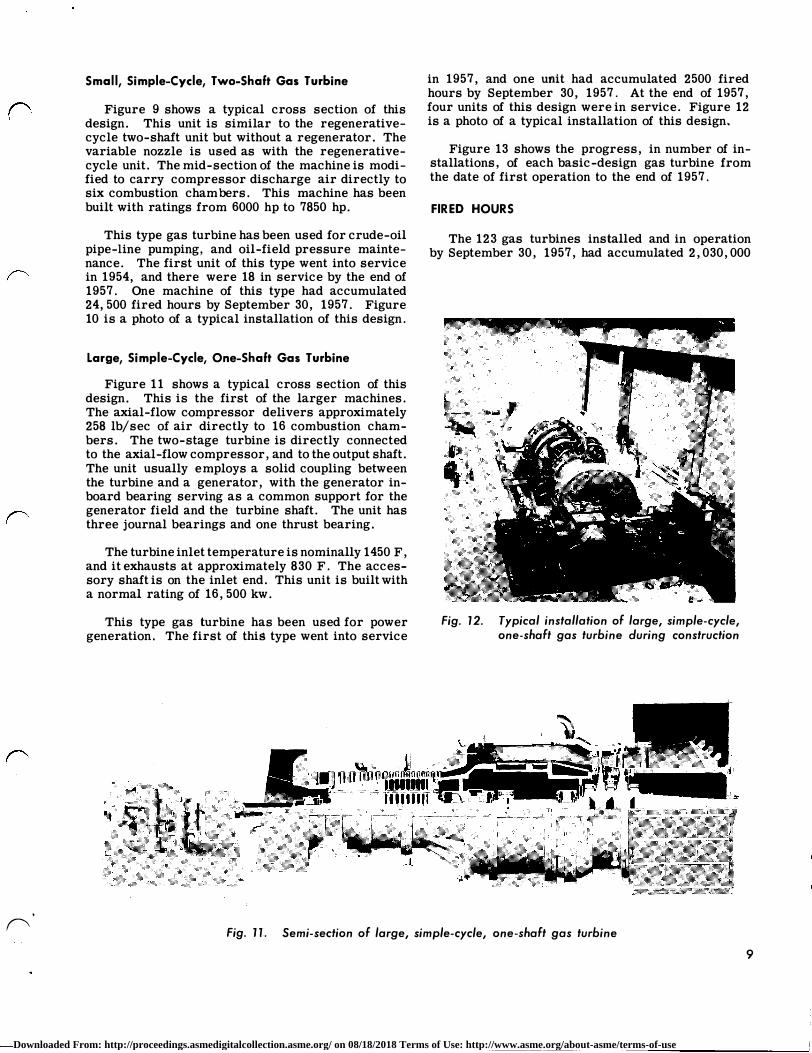
Large, Simple-Cycle, One-Shaft Gas Turbine
Figure 11 shows a typical cross section of this design. This is the first of the larger machines. The axial-flow compressor delivers approximately 258 lb/ sec of air directly to 16 combustion chambers. The two-stage turbine is directly connected to the axial-flow compressor, and to the output shaft. The unit usually employs a solid coupling between the turbine and a generator, with the generator inboard bearing serving as a common support for the generator field and the turbine shaft. The unit has three journal bearings and one thrust bearing.
The turbine inlet temperature is nominally 1450 F, and it exhausts at approximately 830 F. The accessory shaft is on the inlet end. This unit is built with a normal rating of 16, 500 kw.
This type gas turbine has been used for power generation. The first of this type went into service
in 1957, and one unit had accumulated 2500 fired hours by September 30, 1957. At the end of 1957, four units of this design were in service. Figure 12 is a photo of a typical installation of this design.
Figure 13 shows the progress, in number of installations, of each basic-design gas turbine from the date of first operation to the end of 1957.
FIRED HOURS
The 123 gas turbines installed and in operation by September 30, 1957, had accumulated 2,030,000
Fig. 12. Typical installation of large, simple-cycle, one-shaft gas turbine during construction
Fig. 11. Semi-section of large, simple-cycle, one-shaft gas turbine
9
Downloaded From: http://proceedings.asmedigitalcollection.asme.org/ on 08/18/2018 Terms of Use: http://www.asme.org/about-asme/terms-of-use

140�--------------------�
130
120
IIIlD SIMPLE CYCLE, ONE- SHAFT, 4800 HP-7500 HP §RE GENERATIVE, IN TERCOOLED T WO-SHAFT, 5000 HP Elli REGENERATIVE -CYCLE, T WO-S HAFT, 500 HP-7600 Hf> l22ZI SIMPLE-CYCLE, TWO-SHAFI., 6000 HP-7500 HP �SIMPLE-CYCLE, ONE- SHAF 1, 16,000 KW ---....,..r-._.E 110
1001-------------------==-..,,,-nf
901--------------v
80<-------------�·
70 <------------�� ·
60�-----------1
501---------------t-I
401--------------+-I
30�--------+-I
20�-------r."""1i-+-l==l�-ll
10>�------���
01949 1950 1951 1952 1953 1954 1955 1956 1957
Fig. 13. Progress of gas turbine installations showing totals of each basic design
fired hours at this time. This total included 1,340,000 hours for 71 industrial units, 460, 000 hours for 28 transportation units and 225 ,000 hours for 24 powergeneration units. Figure 14 is a curve showing the increase in fired hours for each year and each application. The records were complete to September 30, 1957, and the curves were extrapolated to the end of 1957.
Figure 15 shows accumulated fired hours on each type of fuel burned. The "other" designation includes
10
2400
2200
2000
IJ) 1800 Cl z <t 1600 IJ) ::::> 0 I 1400 I-� 1200 IJ) a:: ::::> 1000 0 I Cl 800 l.LJ a:: LL 600
400
200
0 1953 1954 1955
YEARS 1956
/ I
Fig. 14. Fired hours for all General Electric gas turbines showing total hours and hours for different applications
IJ) Cl
1700
1600
1500
1400
1 300
1200
:i 1100 IJ) 5 1000 I I- 900 z
� 800 ::::> � 700 Cl � 600 LL
500
400
300
200
100
0
O THER: IN CLUDES D ISTI L L ATE, CRUDE O IL, AND DUAL FUE L
v I
/ /
/ / ./ v
v v � .... _....
c --1953 1954 1955
YEARS
I I
I I
I G AS/ I
I I
.... RESIDU�.v /'
OTHER --
1956 1957
Fig. 15. Fired hours for each type of fuel burned
distillate, crude oil and dual fuel. On September 30, 1957, 77 gas-fired units had accumulated 1, 480, 000 fired hours, 34 residual-oil-burning units had 505 ,000 hours, and 12 units with other fuels had 45,000 hours.
STARTING MEANS
These gas turbines are of five basic designs, used in three different applications, with varied use in each application. They burn four different fuels (natural gas, residual oil, distillate, and crude oil), and they operate in a wide range of geographic locations. This range of 1:!onditions has placed varied requirements on the turbine starting means. Five different starting means have been employed to date. These are:
1. Expansion turbine, operating on steam, connected through a clutch to the turbine shaft;
2. Diesel engine, operated through a torque converter, clutch, and speed-increasing gear to the turbine shaft;
3. Diesel-engine-driven generator, connected to a motor, geared to the turbine shaft;
4. Electric motor, with or without speed-increasing gear, through a clutch to the turbine shaft;
-
Downloaded From: http://proceedings.asmedigitalcollection.asme.org/ on 08/18/2018 Terms of Use: http://www.asme.org/about-asme/terms-of-use

. 0
5. Expansion turbine, operating on natural gas, connected through a ciutch to the turbine shait.
A tabulation of these starting means shows:
Expansion turbine - steam 6 machines
Diesel engine - torque converter 7
Diesel engine - generator 27
Electric motor 35
Expansion turbine - natural gas 59
CONTROL
Total 134 machines
The use of a variety of fuels, a wide range of operating conditions, and many uses within an application, has placed a wide range of demands on the gas turbine control system. To meet these demands a variety of systems must be employed. The control systems can be broken into four major categories; manual, semi-automatic, automatic, and remote control. These categories are defined as follows:
Manual Control. The operator energizes auxiliaries, engages the clutch, and starts.the cranking means. He adjusts firing speed, fuel and ignition. He controls acceleration of cranking means and fuel increases to bring the machine to operating speed;
Semi-automatic Control. The operator energizes auxiliaries, engages the clutch, and starts the cranking means. The remainder of cycle, fire and accelerate to speed, is automatic;
Automatic Control. The operator initiates one control switch. The auxiliaries, cranking means, and acceleration are all automatic;
Remote Control. A master switch is energized by a suitable communication such as wire or wireless relay.
A tabulation of these units in operation to date shows:
Manual
Semi-automatic
Automatic
Automatic, with remote provisions
Remote
Total
3
19
55
50
7
134 machines
AVAILABILITY AND RELIABILITY
Certain general functions must be performed in any case. These are: 1. Starting and stopping control; 2. Speed or load control; 3. Temperature and rate of temperature control; 4. Emergency shutdown control.
Figure 16 is a functional diagram for a typical single-shaft gas turbine control, and Fig. 17 is a functional diagram for a two-shaft gas turbine. To meet the variety of requirements necessary, the components used for the functions indicated are electrical, mechanical, hydraulic, pneumatic, or suitable combinations.
EXHAUST HEAT RECOVERY
At the end of 1957, there were 75 regenerative and 59 simple-cycle gas turbines in operation. Of the simple-cycle units, 27 were locomotive units with no exhaust heat recovery. Nine of the remaining 32 simple-cycle gas turbines have some type of exhaust heat recovery. These include waste-heat boilers, both fired and nonfired, and boiler feedwater heating.
AVAILABILITY AND RELIABILITY
USE FACTOR
In order to make an evaluation of performance in service, it is necessary to analyze use factors. The many different applications impose a wide variety of demands on gas turbines. These demands vary from seldom-operated emergency power units, intermittent operation of peaking and transportation units, to the continuous operation of base-load units. A measure of this type of service is the use factor:
Total fired hours Percent Use Factor = Total installed hours x 100
This factor can then be used to evaluate those machines into one of three categories. These are: zero to 20 percent: standby, emergency or peaking units; 20 to 80 percent: transportation, and seasonal units; 80 to 100 percent: base-load units.
Figure 18 is a chart showing use factors for all General Electric gas turbines as of September 30, 1957. This chart also shows the type of fuel burned with respect to use factor.
Other criteria necessary to evaluate performance are availability and reliability factors. These are defined as:
Percent Availability = Installed hours - (Forced outage + Maintenance) hours
Installed Hours x 100
P t R I' b. . Installed hours - Forced outage hours
ercen e ia ihty = Installed Hours x 100
11
Downloaded From: http://proceedings.asmedigitalcollection.asme.org/ on 08/18/2018 Terms of Use: http://www.asme.org/about-asme/terms-of-use

12
FIRING, ACCELERATING,SMAX. FUEL LIMIT RELAY
MAX. TEMP.. 8 TEMP. RATE FUEL LIMIT RELAY
FUEL
IN
CONTROL PANEL
FUEL CONTROL
S YS T EM
AIR IN
TEMPE RATURE. CONTROL
RELAY
(/) <t Cii
E XHAUST OU T
TEMP. DE TECTOR SIGNAL
LOAD )(
NOT INCLUDING E MER G. TRIP ANO ALARM FUNCTIONS
Fig. 16. Typical functional control diagram for single-shaft gas turbine
FIRING,ACCEL----1 ERATING, a MAX.
FUEL LIM I T RELAY
FUEL IN
DO ES NOT INCLUDE EMERGENCY ALARM ANO TRIP FUNC TIONS AIR
IN
MAX.TEMP,8iTEl'ti. TEMPERATURE RATE FUEL LIMIT t-----t �ONTROL
RELAY RELAY
'--����----1o--�����-' � iii
(/) � L.P. GOV. SIGNAL
ID
Fig. 17. Typical functional control diagram for two-shaft gas turbine
TEMP. D E TECTOR SI GNAL
Downloaded From: http://proceedings.asmedigitalcollection.asme.org/ on 08/18/2018 Terms of Use: http://www.asme.org/about-asme/terms-of-use

r
r
18
17
16
15
14
13
V> 12 w z iii I I a:: � I- 10 IL 0 a:: 9 w CD
8 ::;: � z ..J 7
� 6 g 5
4
3
2
EMER SEASONAL BASE PWR TRANSPORTATION, ETC. LOAD
l2Z:l GAS
� RESIDUAL
D OTHER
10 20 30 40 50 60 70 80 90 100
USE FACTOR = FIRED HOURS x 100 INSTALLED HOURS
Fig. 18. Chart showing use factor, and indicating fuel burned
To evaluate these factors in gas turbines, baseload units will be considered because records on them are more accurate. These machines have the highest running demands placed on them, and therefore, accounting for the total installed time has been easier. It is not certain that all records are complete or that down-time has been evaluated the same in every instance, but enough information is available to arrive at approximate availability and reliability factors. Figure 18 shows 30 units in the base-load category at the end ofl 957. Four of these machines have less than 8000 hours and have not reached their first maintenance period; therefore, only 26 units were used in the evaluation.
Figure 19 shows the results of this evaluation and gives the number of turbines considered for each year. The five-year averages for base-load machines are 98. 1-percent availability, and 99. 3-percent reliability.
It is interesting to analyze the three units with use factors greater than 95 percent. These units with very little down-time, for reasons not chargeable to the turbine, essentially have average availability and reliability factors for the base-load group. This means that down-time has not been necessary to
III!IIl FORCED OUTAGE �MAINTENANCE
lillTITI) �1�l�N·��A��EoiF �RUNNING EQUIPMENT OTHER THAN GAS TURBINE OR ITS EQUIPMENT
IOO r-rTTm,.,----,.,.,..,,.�-----,O'l"l"l'=-�l'm"l.,....,--�-a==-i
V> a::
98
96
94
6 92 :r: c 90 w ..J ..J 88 � � 86
1-z 84 w (.) ffi 82 0...
80
78
76
74 L...l"""'"'-----'"""""------'"""""--�"""'��-'"'� 1953 1954 1955 1956
7 17 19 26 TURB. TURB. TURB. TURB.
1957 26
TURB.
Fig. 19. Chart showing use Factor, availability, and reliability. Average for base-load units
maintain high availability and reliability factors. The average for the three units is shown below:
Total Installed Hours 71, 550
Fired Hours 68, 890
Maintenance Hours 850
Forced Outage Hours 470
Other Outages (Hours) 1, 320
Use Factor 96. 32 percent
Availability 98. 17 percent
Reliability 99. 34 percent
Another interesting comparison can be made by looking at time for maintenance outages. Machines with high use factors are usually maintained on tight schedules working around the clock, while those with lower use factors take advantage of periods of no demand to minimize the cost of maintenance. Over the long pull, however, the availability of the lowuse-factor machines remains at a respectable 85 percent or higher, because maintenance is lower in proportion to use. Reliability stays about con-
13
Downloaded From: http://proceedings.asmedigitalcollection.asme.org/ on 08/18/2018 Terms of Use: http://www.asme.org/about-asme/terms-of-use

stant when the general level of maintenance is the same for high- and low-use-factor units.
COMPONENT FAILURES
The accumulation of over 2, 000,_000 fired hours on 134 gas turbines has not been without component part failures. These failures will be reviewed in greater detail later in this paper. Because they play a significant part in availability and reliability factors, they will be listed here. Gas turbines manufactured by the writer's company have experienced the following major difficulties:
15 - First-stage bucket failures.
8 - Damage due to overtemperature.
6 - Second-stage bucket failures.
2 - Turbine wheel failures.
2 - Compressor guide vane failures.
It is interesting to note that while two of these failures occurred on one of the high-use-factor machines discussed above, its use factor is 96. 6, availability 98. 4, and reliability 98. 8.
REVIEW OF PUBLISHED ARTICLES
Four articles, by authors associated with the operation of the gas turbines discussed in this paper, have been reviewed. Selected comments are given here as an indication of the general level of performance and maintenance under which the units have operated.
ROSS C. HILL<3> (27 LOCOMOTIVE GAS TURBINES)
14
Month of August 1956:
"Twenty-five locomotives averaged 432 fired hours out of a possible 744." (Use Factor 58. 2%) "Failures occur at a rate of only 8.7/100, 000 miles."
"Twenty-two reported defects with 14 locomotives involved (15 control, 5 mechanical, 1 wear, one manufacturing error)."
"During the month of August the active fleet of locomotives averaged 12,026 miles each, which was considerably better than any other type of freight locomotive assigned to the same district."
"These locomotives consistently move trains faster than other types of freight power, with the August average being 34. 95 train miles per train hour, this is 6 mph faster than comparable diesel-electric units."
J. W. BLAKE<4> (ONE POWER-GENERATION GAS TURBINE)
The following tabulation was given in Mr. Blake's article:
"Total Hours Installed 31, 452
Hours in Service
Hours Scheduled Out
Hours Forced Out
Hours Scheduled Out Includes
27, 049
4, 369
34
3278 hours maintenance
257 hours available, not in service
800 hours installing second unit."
If the definitions for use factor, availability and reliability as given in this paper are applied to the data given in Mr. Blake's article, the following results are obtained:
Use Factor 86. 1 percent
Reliability 99. 85 percent
Availability 89. 4 percent
A. H. CARAMERos<5> (28 MECHANICAL-DRIVE GAS TURBINES)
Turbine Loading
"This was not really a problem, but is being presented for consideration since all gas turbine designs are not identical. The variable nozzle on our gas turbines gave us the flexibility we needed to handle our various loading conditions. It has allowed us to run the turbine as efficiently as possible, and yet meet the variable dispatching requirements, which at one station, called for maximum horsepower at a LPT speed of 5100 rpm, and, at another station called for minimum (60 percent) horsepower at LPT speed of 5500 rpm. Also, the ambient temperature varied at the
Downloaded From: http://proceedings.asmedigitalcollection.asme.org/ on 08/18/2018 Terms of Use: http://www.asme.org/about-asme/terms-of-use
. ('
stations from 20 to 110 F and in certain cases the station loading conditions were reversed. The additional complexity required for variable nozzles is definitely warranted where the gas turbine is applied as a prime mover for centrifugal compressors on gas transmission lines such as ours."
Maintenance
"The heavy mechanical maintenance and major inspection is handled by a roving crew of six men. They can accomplish a complete "teardown" and assembly in about eighteen, eighthour days.
Our crews work 10 days and are off 4 to give them a maximum amount of time at home. One factory service engineer is available at each overhaul for consulting and factory contact purposes. An average major inspection costs about $10, 000 and we expect about 3 years between inspections. Material replacement has not yet become a factor in these costs since the maximum number of hours on any machine inspected is 16,000 hrs. Fifteen turbines have been inspected to date. It should be noted here that our major inspection time and cost could be reduced 50 percent if our turbines had a horizontal split casing."
Cost of Operation
"The cost of operation of the gas turbine stations has compared favorably with our reciprocating stations. Based on horsepower installed, the gas turbine is about 10 percent cheaper to operate. Based on horsepower developed, the gas turbine runs about 30 percent cheaper to operate. The latter, of course, reflects load factor considerably but when comparing stations of like load factor, this still holds true."
A. L. VAUGHN<6> (8 MECHANICAL-DRIVE GAS TURBINES)
"During the first 27 months, the equipment was available for operation in excess of 90 percent of the time. Considering that these units were not required for lower load factor operations, the turbine plants here are compared on a basis of availability rather than on a basis of hours operated. For comparison, similar data has been compiled and summarized in Table 1 for a vertical and a horizontal reciprocating station which also has operated on a similar basis.
Although the reciprocating station has a better availability record, it should be noted that the
time considered for the turbine includes original station startup and the early months of operation when the so-called "bugs" had to be worked out of the equipment.
Today, we are confident that the over-all reliability of a turbine station will be comparable with our reciprocating stations. We have one station in which all four turbines have operated continuously over two months without a shutdown. This record may well have been extended, had there been continued demand for the equipment.
TABLE 1
STA TIO,_. TIME RECORD
Percent of Total Possible
Description Operating Hours
Gas Turbine Horizontal Vertical Station Engine Station Engine Station
HoW'S Operatin g 3316 37.78 29.67 * Dispatching Orders 58.35 60.19 68.76
Total Availability 91.51 9 7.97 98.43 Downtime
Equipment Failure 4 50 0.30 017 Overhaul 8 Inspection 3.99 173 1 .40 Total 100.00 100 00 100 00
* Equipment 1s operable but not required
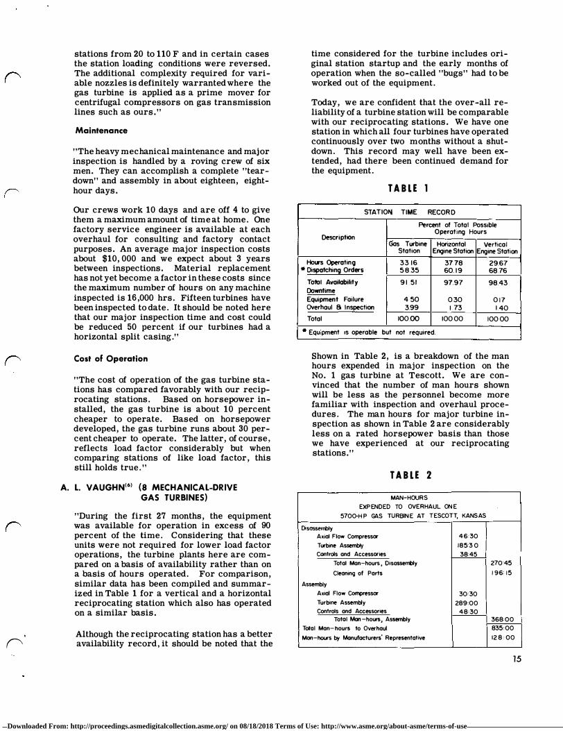
Shown in Table 2, is a breakdown of the man hours expended in major inspection on the No. 1 gas turbine at Tescott. We are convinced that the number of man hours shown will be less as the personnel become more familiar with inspection and overhaul procedures. The man hours for major turbine inspection as shown in Table 2 are considerably less on a rated horsepower basis than those we have experienced at our reciprocating stations."
TABLE 2
MAN- HOURS
EXPENDED TO OVER HAUL ONE
5700-HP GAS TURBINE AT TESCOT T, KANSAS
Disassembly Axial F low Compressor 4 6 :30
Turbine Assembly 185:3 0 Controls and Accessories 38:45
Total Man-hours, Oisasserrbly 270:45
Cleaning of Parts 196:15
Assembly
Axial Flow Compressor 30:30 Turbine Assembly 289:00 Controls and Accessories 4 8 :30
Totol Man-hours, Assembly 368:00 Total Man-hours to Overhaul 835:00
Mon-hours by Manufacturers' Representative 12 8:00
15
Downloaded From: http://proceedings.asmedigitalcollection.asme.org/ on 08/18/2018 Terms of Use: http://www.asme.org/about-asme/terms-of-use

PROBLEMS AND SOLUTIONS
FIRST-ST AGE BUCKETS
Five of the first-stage bucket failures listed earlier were in buckets of Nimonic-80 material. Failure occurred at a point between 16, 000 and 20, 000 fired hours.
The buckets which failed experienced grain boundry separation. This separation was caused by slight material structural instability at operating temperatures, due to aging of the material at temperatures close to the full-load operating temperature of the bucket.
It appears that the long-term stability of the material can be increased indefinitely by a special heat treatment involving double aging. This treatment combined with non-destructive testing has been used to correct all buckets of this type in service to avoid possible additional failures. Figure 20 is a photo of a typical failure of this type.
COMPOSITE TURBINE WHEELS
Two failures were listed earlier which occurred in 1952 and 1955. One failure occurred in the dovetail area (bucket connection point), and the other failure was a separation between rim and wheel cen-
16 Fig. 20. Nimonic-80 First-stage bucket Failure
ter. This wheel employed a high-temperature rim welded to a wheel center of lower alloy. The failure occurred in the weld area. Sonic testing has been used extensively to inspect all composite wheels in service, and it is now a regular part of each scheduled maintenance inspection. With this kind of inspection there have been no further failures and the necessary control has been established to follow the sonic history of each composite wheel. Figure 21 is a photo of the dovetail failure.
COMBUSTION SYSTEM
One of the earliest problems encountered with residual-fuel-burning units was the short life (100 to 300 hours) of combustion liners, and the short servicing interval (50 to 75 hours) of fuel nozzles.
Damage to the cap and liner consisted of the burning away of liner tabs, or liner hooks in local areas, and warping which then led to further overheating, closing off of cooling air slots, and rapid deterioration of the next section downstream. A new liner and fuel-nozzle combination was developed, (7) usually referred to as air-swirl nozzle and louvered liner. In the louvered liner, this situation is improved by admitting air through a large number of closely spaced openings, formed by punching small portions of the liner surface outward. The use of many such openings permits a nearly continuous thin sheathing film, and by proper choice of louver size, spacing and location, cooling can be increased in local areas, which tend to run hot, and decreased in regions which run cool. The increase in life of these parts is discussed later. Figure 22 is a cross section of the air-swirl nozzle and louvered-liner combination.
THRUST BEARINGS
During the early operation of the two-shaft mechanical-drive gas turbines, a series of load-turbine thrust-bearing failures occurred. The cause of these failures was found to be high static thrust loads at "break away" of the gas turbine load shaft and highpressure (600-800 psi) single-stage centrifugal compressor. These failures were eliminated by increasing the effective area of the active thrust bearing to carry the high static loads.
COMPRESSOR INLET GUIDE VANES
As previously noted in this paper, two failures were listed as inlet-guide-vane failures. The unshrouded guide vanes failed in fatigue. Shrouding of the guide vanes eliminated the trouble. This shrouding has been entirely successful since 1955. \.
Downloaded From: http://proceedings.asmedigitalcollection.asme.org/ on 08/18/2018 Terms of Use: http://www.asme.org/about-asme/terms-of-use

Fig. 21. Wheel failure in dovetail section
FUEL OIL ATOMIZING AIR
0
SECTION #3
SCALE-INCHES
Fig. 22. Section view of combustion chamber with louvered liner
HEAT SHOCK
Fifteen first-stage bucket failures were reported earlier� ten were attributed to heat or thermal shock. \8) Thermal shock occurs when the buckets are subjected to a very rapid combustion-gas temperature rise. The outer skin of the bucket attempts to expand since it feels the high temperature almost immediately. The bulk of the material toward the middle of the bucket, however, warms at a slower
rate. Since the outer skin is trying to expand faster than the inner part of the bucket, it is subjected to very high cgmpressive stresses. These high stresses (occurring at every startup) plus minute notches on the leading edge due to corrosion and/or foreign particles in the gas stream cause a crack to start.
The correction for this condition is, of course, to reduce temperature gradients during starting. This places a precise demand on the control system. It
17
Downloaded From: http://proceedings.asmedigitalcollection.asme.org/ on 08/18/2018 Terms of Use: http://www.asme.org/about-asme/terms-of-use
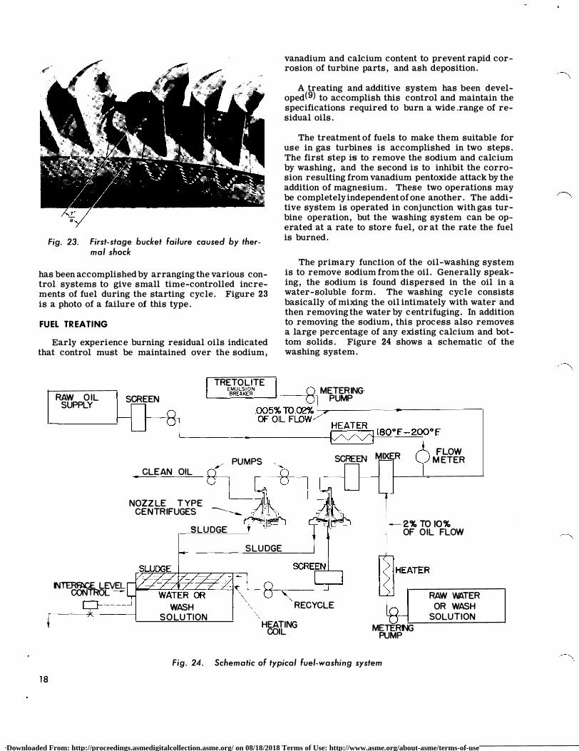
Fig. 23. First-stage bucket failure caused by thermal shock
vanadium and calcium content to prevent rapid corrosion of turbine parts, and ash deposition.
A treating and additive system has been developed(9) to accomplish this control and maintain the specifications required to burn a wide.range of residual oils.
The treatment of fuels to make them suitable for use in gas turbines is accomplished in two steps. The first step is to remove the sodium and calcium by washing, and the second is to inhibit the corrosion resulting from vanadium pentoxide attack by the addition of magnesium. These two operations may be completely independent of one another. The additive system is operated in conjunction with gas turbine operation, but the washing system can be operated at a rate to store fuel, or at the rate the fuel is burned.
has been accomplished by arranging the various control systems to give small time-controlled increments of fuel during the starting cycle. Figure 23 is a photo of a failure of this type.
The primary function of the oil-washing system is to remove sodium from the oil. Generally speaking, the sodium is found dispersed in the oil in a water-soluble form. The washing cycle consists basically of mixing the oil intimately with water and then removing the water by centrifuging. In addition to removing the sodium, this process also removes a large percentage of any existing calcium and bottom solids. Figure 24 shows a schematic of the washing system.
FUEL TREATING
Early experience burning residual oils indicated that control must be maintained over the sodium,
RAW OIL SUPPLY
SCREEN
CLEA N OIL
NOZZLE T Y PE
TRETO LITE EMULSION METERING· L_��BR�E�AK�E�R�__J��-t""'il PUMP
,-PUMPS
8 SCREEN MIXER
CENTRIFUGES ----------
FLOW M ETER
SLUDGE -2%TOIO%
OF OIL FLOW
18
N�LEVEL CONTROL � ____ _J
WASH SOLUTION
SLUDGE
\ '
RECYCLE
HEATING COIL METER NG
PUMP
Fig. 24. Schematic of typical fuel-washing system
RAW WATER
OR WASH
SOLUTION
Downloaded From: http://proceedings.asmedigitalcollection.asme.org/ on 08/18/2018 Terms of Use: http://www.asme.org/about-asme/terms-of-use

. 0
Fig. 25. Typical base-mounted gas turbine with auxiliaries
SECOND-ST AGE BUCKETS
Six second-stage bucket failures were listed earlier, and were attributed to material. These buckets were originally made of Timken material, and the failures were from fatigue due to vibration.
These buckets are now made of crucible 422 alloy, and are operating satisfactorily.
BASE MOUNTING
Early gas turbines were shipped with the turbine as an assembled unit, and the oil tank, piping, wiring, and accessories shipped as separate components. Installation experience indicated, in some cases, relatively long installation times, as well as storage and handling problems.
To reduce the installation time and cost to a minimum, gas turbines rated to approximately 13, 000 hp, were modified to base mounting with the base containing assembled piping, wiring, auxiliaries, and the oil tank. Figure 25 shows a typical base-Il}.ounted gas turbine with its auxiliaries.
HORIZONTAL-SPLIT CASINGS
Many early gas turbines had some major casings with vertically split joints, rather than a split at the horizontal centerline. While vertical joints, in some
cases, have an advantage in controlling temperature distortion, operating experience indicated disadvantages from a maintenance point of view. To keep major maintenance time as low as possibl€, all gas turbines are now built with casings split at the horizontal centerline. Figure 26 shows a typical unit with the top casings removed.
LIFE OF PARTS COMBUSTION SYSTEM
Fuel nozzles and combustion liners using naturalgas fuel have operated on many units in excess of 30, 000 fired hours without signs of distress. In some cases, minor repair is required at Ul.e 8000-hour, or 24, 000-hour inspections. Fuel nozzles, used with residual oil in intermittent service (frequent stops and starts), require cleaning at intervals of approximately 400 fired hours. This same fuel nozzle in continuous operation is expected to require cleaning at about 2500-hour intervals.
Combustion liners for intermittent residual-oil operation are operating satisfactorily for 3000 to 5000 fired hours. They are normally inspected at 400-fired-hour intervals, in conjunction with the cleaning of fuel nozzles. The life of these liners in continuous operation with residual fuel is not established, but they will probably be inspected at 2500-hour intervals again, in conjunction with fuelnozzle servicing.
19
Downloaded From: http://proceedings.asmedigitalcollection.asme.org/ on 08/18/2018 Terms of Use: http://www.asme.org/about-asme/terms-of-use

Fig. 26. View of a two-shaft gas turbine with top casing's removed
TURBINE NOZZLES
Natural-gas-fired units have first- and secondstage nozzles in operation in excess of 30,000 fired hours. Minor repair is sometimes required at inspection intervals; usually welding of small cracks in the trailing edge of the first-stage nozzle ·partitions. Turbines burning residual fuel hi intermittent service have required some replacement of firststage nozzles at 5000 to 10, 000 hours. The life of this nozzle is largely dependent on the condition of the combustion system, and the number of starts or heat-shock cycles it has been exposed to. The 5000-to 10, 000-hour life includes operation previous to improved combustion systems, and heat-shock control modifications, therefore, present life should be somewhat improved, but how much is not established at this time. Many second-stage nozzles on residualburning units are still in operation, with minor repair, after more than 20, 000 fired hours.
TURBINE BUCKETS
Gas turbines burning natural gas have first- and second-stage buckets in operation in excess of 30,000 fired hours without signs of distress. Units with Nimonic-80 buckets, as previously noted, required a special heat treating of these buckets at approximately 16, 000 fired hours before continuing in service.
Residual-oil-burning units in intermittent serv'ice have turbine buckets, both first and second stages, in service in excess of 20, 000 hours.
20
Exceptions, in this case, are the first-stage buckets that failed due to heat shock before control modifications.
TURBINE WHEELS
The turbine wheels are designed for at least 100, 000 hours of service. There have been only two failures up to September 30, 1957, as previously listed. Already many gas-fired wheels have operated successfully for well over 30, 000 hours. A larger number of oil-fired machines have wheels which have operated successfully for well over 20, 000 hours, even though they have been subjected to frequent starts and rapid variations in load. In some cases, minor repairs are required at inspection intervals. This usually consists of grinding out minute cracks in the dovetail area.
SUMMARY
Operating conditions have a major effect on the life of some of the component parts. For example, gaseous fuels produce less deterioration than residual fuels. Likewise, continuous service is less severe than intermittent service. As service experience is gained, designs are being modified continuously to improve the life of the parts under all operating conditions.
Table 3 shows the life which has been obtained to date under favorable conditions, such as continuous operation on gaseous fuels and also under the most
Downloaded From: http://proceedings.asmedigitalcollection.asme.org/ on 08/18/2018 Terms of Use: http://www.asme.org/about-asme/terms-of-use

. 0
severe conditions, such as railroad service where the machines are not only operated on residual fuel, but also subjected to frequent starts and rapid load variations. For residual-fuel machines in normal industrial service, the life of the components should be appreciably greater than for railroad service.
TABLE 3
Gas-fired Residual-oil Continuous Intermittent
Service Service
Combustion liners Over 30, 000 3000 to 5000 hours hours
Fuel nozzles Over 30, 000 Over 10, 000 hours hours
First-stage turbine Over 30, 000 5000 to nozzle hours (minor 10, OOOhours
repairs) depending on service con-ditions
Second-stage turbine Over 30, 000 Over 20, 000 nozzle hours hours (minor
repairs)
Turbine buckets Over 30, 000 Over 20, 000 hours hours
Turbine wheels Over 30, 000 Over 20, 000 hours (minor hours (minor repairs) repairs)
MAINTENANCE
GENERAL
The actual maintenance practices vary greatly with the type of fuel burned, and the type of service in which the gas turbine operates. In general, with gas-fired high-use-factor machines, it is recommended that partial inspections be made at yearly (8000 hours) intervals, and complete inspections be made every three years (24, 000 hours). In actual practice, many machines receive their only inspections at 16, 000-hour intervals and in a few cases at intervals even longer. Residual-oil-fired machines in intermittent service (50- to 60-percent use factors, with frequent stops and starts) generally receive a yearly (4000-5000 fired hours) partial inspection, and every two years (8000-10, 000 fired hours) a complete inspection. These units also receive minor combustion inspections at shorter intervals.
Fig. 27. Inspector using a Boresonic instrument to inspect combustion-chamber liner
COMBUSTION SYSTEM
Gas-fired units receive combustion system inspections usually in conjunction with the partial, and major inspections listed above. Residual-oil-burning units, as noted previously, require fuel-nozzle servicing at 400-fired-hour intervals. Combustion liners are inspected in conjunction with this servicing. The inspection at this time is with a borescope to keep down-time at a minimum, further inspection is dictated by observations with the borescope. Figure 27 is a photo of the borescope in use.
AXIAL-FLOW COMPRESSORS
Under certain conditions, in some applications oil vapor, dust, s.and, or water-soluble compound� may be carried into the axial-flow compressor inlet.
In the case of water-soluble compounds, or the combination of oil vapor and dust, a build-up on compressor blades may occur, reducing compressor efficiency and capacity. The rate of build-up determines the compressor cleaning interval. An injection method of cleaning those compressors, while running, has been developed. In the case of sand and/or cinders entering compressors without inlet air filters, it has been necessary to reblade at intervals as short as 15, 000 hours. The interval depends entirely on the severity of the abrasive intake.
21
Downloaded From: http://proceedings.asmedigitalcollection.asme.org/ on 08/18/2018 Terms of Use: http://www.asme.org/about-asme/terms-of-use

NOZZLES, BUCKETS AND WHEELS
These items are inspected partially during the minor inspection and inspected thoroughly during the major inspection. The inspection consists usy.ally of visual, plus liquid-penetrant testing, and in the case of composite wheels, sonic testing. Necessary minor repairs are made, based on the findings of these tests.
TIME REQUIREMENTS
Listed above are two very general inspections that apply to all gas turbines, these are the periodic minor and major inspections. There is not very much practical experience, recorded to date, as to time and manpower requirements to perform these inspections. But, indications based on experience to date, are that the minor inspection requires 350 to 450 manhours, and the major inspection 800 to 900 manhours. It could be expected that these requirements will be decreased with practice and experience, and should approach 0. 1 manhour/hp for a major inspection and 0. 04 manhour /hp for a minor inspection (present ratings).
TRENDS
NEW BASIC DESIGNS
Past operating experience indicated the need for additional ratings and types. In 1958, three new basic designs will go into commercial operation for the first time. A brief description of these units follows:
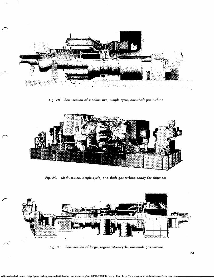
Medium-Size, Simple-Cycle, One-Shaft Gas Turbine
Figure 28 shows a cross section of this design. The axial-flow compressor discharges into ten combustion chambers; by reversing air flow direction, essentially the combustion chambers are wrapped around the air compressor. The combustion chambers discharge directly into a two-stage turbine, directly connected to the axial-flow compressor. The nominal turbine inlet temperature is 1450 F and it e:Xhausts at approximately 850 F. The output shaft is on the inlet end, and the accessory shaft is on the exhaust end. The shaft is supported by two jou.rnal bearings and one thrust bearing.
This design is scheduled to be built with ratings from approximately 10, 700 hp to 14, 200 hp. This machine is scheduled for use in locomotives, refinery compressor drives, pipe-line compressor drives, power generation, and general mechanicaldrive applications. Figure 29 shows a unit of this design ready for shipment.
22
Large, Regenerative-Cycle, One-Shaft Gas Turbine
Figure 30 shows a cross section of a gas turbine of this design. The unit is very similar to the large, simple-cycle, one-shaft unit described earlier, but in this case it is a regenerative unit. The axial-flow compressor discharges to a regenerator, and the return from the regenerator is directed to eight combustion chambers, arranged in two "pods". This unit is scheduled for power generation, and will be built with ratings of approximately 16, OOOkw. Figure 31 shows a unit of this design on factory test.
Large, Simple-Cycle, One-Shaft Gas Turbine
Figure 32 shows a cross section of this design. This will be the largest General Electric gas turbine built to date. It is a simple-cycle unit, with the air-compressor discharge air flow reversing direction to enter twelve combustion chambers wrapped around the later stages of the air compressor.
The combustion chambers discharge into a twostage turbine operating at a nominal inlet temperature of 1450 F. The shaft will be supported by two journal bearings and one thrust bearing. The turbine shaft will share one iournal bearing with a load gear. This gear drive can be arranged for either 50- to 60-cycle generation.
This unit will be built for power generation, with ratings of approximately 21, 800 kw. Figure 33 shows a unit of this design on factory test.
Figure 34 shows yearly, since 1952, the number of each basic-design gas turbine in operation, and shows the approximate number of each design scheduled for operation in 19 58.
FEATURES
In 1958, three new gas turbine designs will be operated in commercial service for the first time with ratings up to 21, 800 kw. A new and different governing system will be used for the first time. This is a development for locomotive service. There will be an increase in the number of remote-control units, the first remote-control dual-fuel unit going into operation in 19 58. There will be more residualoil-burning units installed than gas-burning units.
Figure 35 shows the yearly totals from 1953, of all General Electric gas turbines installed, and gives the approximate total schedules for first operation during 1958. The number of units burning each type fuel is shown.
\.
Downloaded From: http://proceedings.asmedigitalcollection.asme.org/ on 08/18/2018 Terms of Use: http://www.asme.org/about-asme/terms-of-use
' ('
Fig. 28. Semi-section of medium-size, simple-cycle, one-shaft gas turbine
Fig. 29. Medium-size, simple-cycle, one-shaft gas turbine ready for shipment
\
.a.w:. ,
...___._____.__ n�
Fig. 30. Semi-section of large, regenerative-cycle, one-shaft gas turbine
i
23
Downloaded From: http://proceedings.asmedigitalcollection.asme.org/ on 08/18/2018 Terms of Use: http://www.asme.org/about-asme/terms-of-use

24
Fig. 31. Large, regenerative-cycle, one-shaft gas turbine on factory test
��µ.illj-' ' ' ' ' ' ' ' ' ' ' ,• '
Fig. 32. Semi-section of large, simple-cycle, one-shaft gas turbine
Downloaded From: http://proceedings.asmedigitalcollection.asme.org/ on 08/18/2018 Terms of Use: http://www.asme.org/about-asme/terms-of-use

(' "--
'
('
Fig. 33. Large, simple-cycle, one-shaft gas turbine on Factory test
190
18 1 70
1 60
1 50
140
1 30
1 20
1 10
100
90
80
!lilil S IMPLE-CYCLE, ONE-SHAFT, 4800 HP- 7500 HP
§ REGENERATIVE, INTERCOOLED,-T WO- SHAFT, 5000 KW
mfill REGENERATIVE -CYCLE, TWO- _ SHAFT, 5000 HP- 7500 HP
� SIMPLE-CYCLlc T WO-SHAFT, 6000 HP-7 0 HP
� SIMPLE - CYCLE, ONE-SHAFT, 16,000 KW // mm SIMPLE-CYCLE, ONE-SHAFT,-fr-10,700 HP- 1 4,200 HP
c:::::J REGENERATIVE -CYCLEW ONE-SHAFT, 16,000 K SIMPLE- CYCLE6 ONE -
SHAFT, 21,80 KW
1954 1955 1956 1957 1958 Yf;AR
Fig. 34. Progress of gas turbine installations showing total of each basic design, and indicating installations scheduled for 1958
Ul LI.I z iii a: � I-LL 0 a: LI.I ID ::;; � z __J � 0 I-
I I
1 80 OTHER: DISTILLATE, CRUDE OIL, ----+----'""' AND DUAL FUEL
I 1 60 1----+---+---+---+---+--+-1----<
1954 1955 1956 1 957 YEAR
I I
I I
1958
Fig. 35. Progress of gas turbine installations showing fuel burned and indicating installations scheduled For 1958
25
Downloaded From: http://proceedings.asmedigitalcollection.asme.org/ on 08/18/2018 Terms of Use: http://www.asme.org/about-asme/terms-of-use
CONCLUSIONS The gas turbine has found, and will continue to
find many uses in different applications. The flexibility required by various fuels, control systems, starting means, basic applications and waste-heat recovery requirements has been demonstrated. The range of ratings and cycles available are powering their applications successfully. Reliability and availability are of a high order. There have been serious problems in development, but none which have· not been solved reasonably and quickly.
Maintenance requirements are proving to be low, and time to perform this maintenance short. The "hot" parts in the gas turbine are demonstrating long life.
The gas turbine has found its place throughout industry, and its use is increasing because the factors affecting operation and maintenance are very favorable when compared with other prime movers !II
REFERENCES 1. "Design Features of a 4800 HP Locomotive Gas
Turbine Power Plant", by Alan Howard, presented to semiannual meeting of ASME, June 1947.
2. ''Design Features of a 5000 HP Gas Turbine" by B. O. Buckland and D. Berkey, ASME paper No. 51-A-113.
3. "What Causes Gas Turbine Road Failures", by Ross C. Hill, Railway Locomotives and Cars, May, 1957, Vol. 131, No. 5.
4. "Gas Turbine on the Line 27 , 000 Hours", by J. W. Blake, Electric Light and Power, May, 19 53, Vol. 31, No. 6.
5. "El Paso 's Gas Turbine Operating Experience", by A. H. Carameros, ASME paper No. 56-GTP-6.
6. "Operating Considerations in the Application of Gas Turbine-driven Centrifugal Pipe-line Compressors", by A. L. Vaughan, ASME paper No. 56-PET- 13.
--
7. '1ncreased Life for Gas Turbine Combustion Systems Burning Residual Fuel", by R. W. Macaulay and C. M. Gardiner, ASME paper No. 56-GTP-11.
8. "Transient Temperature and Thermal Stress in Locomotive Gas Turbine Buckets", by :M.rs. F. F. Buckland and Mr. J.B. Gatzemeyer, ASME paper No. 55-A-179.
--
9. "Modified Residual Fuel for Gas Turbines", by B. 0. Buckland and D. G. Sanders, ASME paper 54-A-246.
*When this paper was written, the author included information and expressed opinions believed to be correct and reliable.
26
Because of the constant advance of technical knowledge, the widely differing conditions of possible specific application, and the possibility of misapplication, any application of the contents of this paper must be at the sole discretion and responsibility of the user.
Downloaded From: http://proceedings.asmedigitalcollection.asme.org/ on 08/18/2018 Terms of Use: http://www.asme.org/about-asme/terms-of-use