Open Standards for Sensor Information Processing · Open Standards for Sensor Information...
49
ORNL/TM-2009/145 Open Standards for Sensor Information Processing July 2009 Prepared by Line C. Pouchard Steve Poole Josh Lothian
Transcript of Open Standards for Sensor Information Processing · Open Standards for Sensor Information...

ORNL/TM-2009/145
Open Standards for Sensor Information Processing
July 2009 Prepared by Line C. Pouchard Steve Poole Josh Lothian

DOCUMENT AVAILABILITY Reports produced after January 1, 1996, are generally available free via the U.S. Department of Energy (DOE) Information Bridge. Web site http://www.osti.gov/bridge Reports produced before January 1, 1996, may be purchased by members of the public from the following source. National Technical Information Service 5285 Port Royal Road Springfield, VA 22161 Telephone 703-605-6000 (1-800-553-6847) TDD 703-487-4639 Fax 703-605-6900 E-mail [email protected] Web site http://www.ntis.gov/support/ordernowabout.htm Reports are available to DOE employees, DOE contractors, Energy Technology Data Exchange (ETDE) representatives, and International Nuclear Information System (INIS) representatives from the following source. Office of Scientific and Technical Information P.O. Box 62 Oak Ridge, TN 37831 Telephone 865-576-8401 Fax 865-576-5728 E-mail [email protected] Web site http://www.osti.gov/contact.html
This report was prepared as an account of work sponsored by an agency of the United States Government. Neither the United States Government nor any agency thereof, nor any of their employees, makes any warranty, express or implied, or assumes any legal liability or responsibility for the accuracy, completeness, or usefulness of any information, apparatus, product, or process disclosed, or represents that its use would not infringe privately owned rights. Reference herein to any specific commercial product, process, or service by trade name, trademark, manufacturer, or otherwise, does not necessarily constitute or imply its endorsement, recommendation, or favoring by the United States Government or any agency thereof. The views and opinions of authors expressed herein do not necessarily state or reflect those of the United States Government or any agency thereof.

ORNL/TM-2009/145
Extreme Scale Systems Center and Computer Science and Mathematics Division
OPEN STANDARDS FOR SENSOR INFORMATION PROCESSING
Line C. Pouchard
Steve Poole
Josh Lothian
Chris Groer
Date Published: July 2009
Prepared by OAK RIDGE NATIONAL LABORATORY
Oak Ridge, Tennessee 37831-6283 managed by
UT-BATTELLE, LLC for the
U.S. DEPARTMENT OF ENERGY under contract DE-AC05-00OR22725

iii
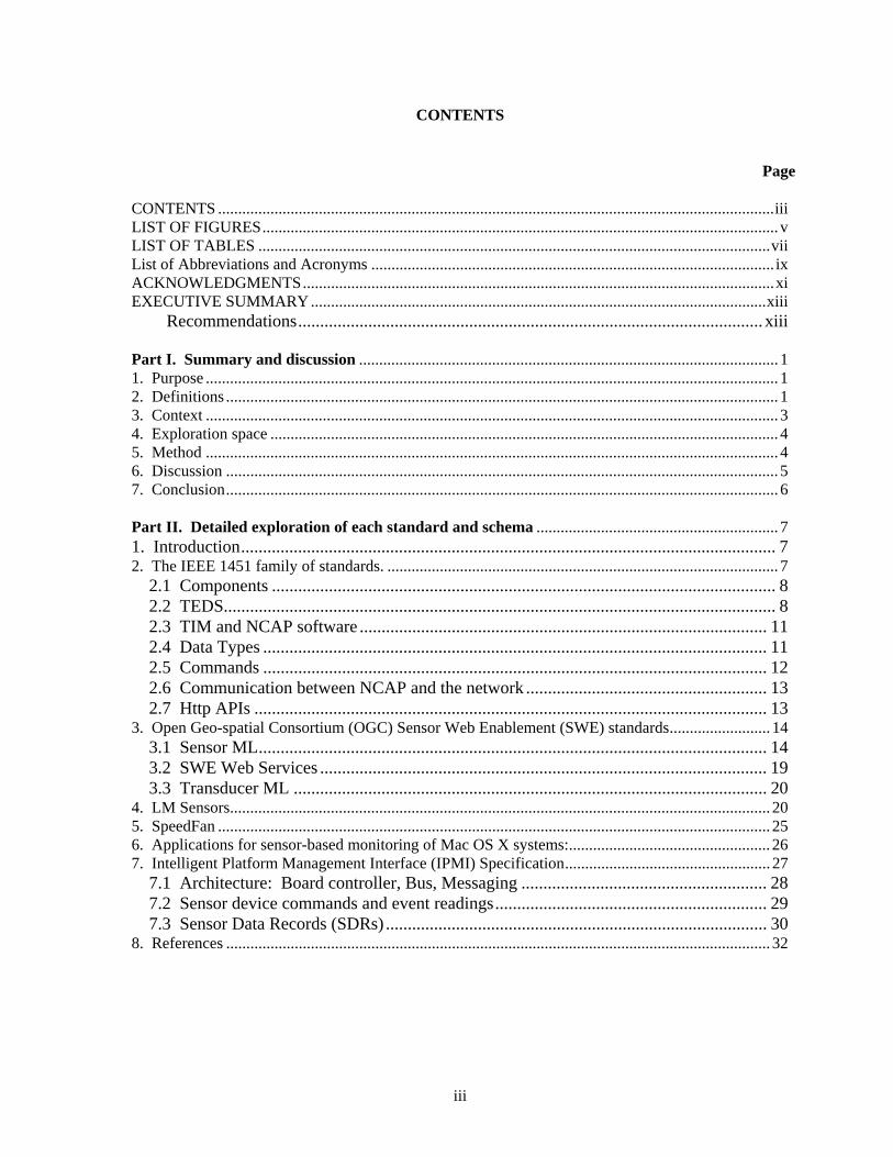
CONTENTS
Page CONTENTS ..........................................................................................................................................iii LIST OF FIGURES................................................................................................................................ v LIST OF TABLES ...............................................................................................................................vii List of Abbreviations and Acronyms .................................................................................................... ix ACKNOWLEDGMENTS.....................................................................................................................xi EXECUTIVE SUMMARY.................................................................................................................xiii
Recommendations.......................................................................................................... xiii Part I. Summary and discussion ........................................................................................................ 1 1. Purpose .............................................................................................................................................. 1 2. Definitions ......................................................................................................................................... 1 3. Context .............................................................................................................................................. 3 4. Exploration space .............................................................................................................................. 4 5. Method .............................................................................................................................................. 4 6. Discussion ......................................................................................................................................... 5 7. Conclusion......................................................................................................................................... 6 Part II. Detailed exploration of each standard and schema ............................................................ 7 1. Introduction.......................................................................................................................... 7 2. The IEEE 1451 family of standards. ................................................................................................. 7
2.1 Components ................................................................................................................... 8 2.2 TEDS.............................................................................................................................. 8 2.3 TIM and NCAP software ............................................................................................. 11 2.4 Data Types ................................................................................................................... 11 2.5 Commands ................................................................................................................... 12 2.6 Communication between NCAP and the network ....................................................... 13 2.7 Http APIs ..................................................................................................................... 13
3. Open Geo-spatial Consortium (OGC) Sensor Web Enablement (SWE) standards......................... 14 3.1 Sensor ML.................................................................................................................... 14 3.2 SWE Web Services ...................................................................................................... 19 3.3 Transducer ML ............................................................................................................ 20
4. LM Sensors...................................................................................................................................... 20 5. SpeedFan ......................................................................................................................................... 25 6. Applications for sensor-based monitoring of Mac OS X systems:.................................................. 26 7. Intelligent Platform Management Interface (IPMI) Specification................................................... 27
7.1 Architecture: Board controller, Bus, Messaging ........................................................ 28 7.2 Sensor device commands and event readings.............................................................. 29 7.3 Sensor Data Records (SDRs) ....................................................................................... 30
8. References ....................................................................................................................................... 32


v
LIST OF FIGURES
Figure Page Figure 1. OGC SWE standards serve as an interface between IEEE 1451 and a network.................... 7 Figure 2. The IEEE 1451 family of sensors, its organization and internal and external connections. .. 9 Figure 3. The communication and service stack for the NCAP and TIM modules............................. 10 Figure 4. NCAP/Application communication via http. ....................................................................... 13 Figure 5. The vision of SWE (courtesy Sheth, 2008).......................................................................... 14 Figure 6. Topology of processes in SensorML (courtesy: Botts, 2008).............................................. 15 Figure 7. LM sensors architecture. ...................................................................................................... 24 Figure 8. SpeedFan data representation............................................................................................... 25 Figure 9. IPMI in a managed platform. ............................................................................................... 27 Figure 10. IPMI connection diagram................................................................................................... 28


vii
LIST OF TABLES Table Page 1. The generic format of a TEDS ......................................................................................................... 11 2. IEEE 1451 Data Types ..................................................................................................................... 12 3. SensorML elements .......................................................................................................................... 16 4. Elements defined for all processes (Abstract Process Type)............................................................ 16 5. Elements for input and output signals, and parameters .................................................................... 17 6. SensorML elements in the metadata group. ..................................................................................... 18 7. Elements specific to each process type............................................................................................. 19 8. Results of sensors-detect for reefcreature.ornl.gov .......................................................................... 21 9. Scanning results for reefcreature. ..................................................................................................... 21 10.Scanning results for desktop running Ubuntu. ................................................................................ 22 11. LM sensors run on PID 1 and a winbond Super I/O chip: w83627hf-isa-0290 ............................. 23 12. LM sensors run on POD 1 and a winbond Super I/O chip: w83627hf-isa-0290............................ 23 13. Sensor Device Commands.............................................................................................................. 29 14. Information provided in SDRs ....................................................................................................... 30


ix
LIST OF ABBREVIATIONS AND ACRONYMS
API Application Programming Interface BIOS Basic Input/Output System CIM Common Information Model CPU Central Processing Unit DCAT The ORNL Data Collection and Analysis Tool DMTF Distributed Management Task Force FRU Field Replaceable Unit HPC High Performance/Productivity Computing I/O Input/output IPMI Intelligent Platform Management Initiative LAN Local Area Network LM Linux Monitoring ML Mark-up Language MW Mega-watt NIST National Institute of Standards and Technology OEM Original Equipment Manufacturer OGC Open Geo-spatial Consortium ORNL Oak Ridge National Laboratory OS Operating System RAS Reliability, Availability, Servicebility RPM Revolution Per Minute SML Sensor Model Language SWE Sensor Web Enablement TEDS Transducer Electronic Data Sheet TCO Total Cost of Ownership TML Transducer Mark-up Language XML Extensible Mark-up Language


xi
ACKNOWLEDGMENTS
This work was supported by the United States Department of Defense and used resources of the Extreme Scale Systems Center at Oak Ridge National Laboratory.


xiii
EXECUTIVE SUMMARY
This document explores sensor standards, sensor data models, and computer sensor software in order to determine the specifications and data representation best suited for analyzing and monitoring computer system health using embedded sensor data. We review IEEE 1451, OGC Sensor Model Language and Transducer Model Language (TML), LM sensors, and Intelligent Platform Management Initiative (IPMI).
The sensors of interest for this report may be new technologies or legacy devices; they are networked and may communicate with a server or external device to store data. Mechanisms on the sensor side send information to a network; applications on the network access sensors for commands and data processing.
1. IEEE 1451-compliant sensors leave it to the user to determine the type of network. The IEEE 1451 group of standards focuses on decoupling sensor data, metadata, and commands, thus ensuring the existence of a common API to a network.
2. The OGC sensor standards use Web protocols for data transport. TML is a well-documented
specification with implementation references. TML is operational in many domains, including military applications. In practice, TML is economical for data transport on the Web but contains very little metadata. SensorML is better suited if rich metadata is needed, and is quite complex, which can be a drawback or a benefit.
3. LM sensors is a set of open source libraries for Linux that can report information about
temperatures, voltages, fan RPMs and other from sensors embedded in motherboards and cpus. As open source software it is available for inspection, testing, and extensible for customized needs. LM sensors depend on the Linux community to write drivers for new sensors and hardware.
4. IPMI is the result of a Dell, Intel, NEC, and HP initiative. The IPMI specification reports the
same information as LM sensors and other log files. Proprietary IPMI tools are sophisticated and contain high-level system management interfaces.
The report concludes that no single specification or library studied in this report satisfies by itself the
goal of providing a sensor model suitable to analyze sensor data provided by all computer manufacturers. IPMI and LM sensors can be used together, with LM sensors reporting IPMI data through its IPMI driver, but this does not add validity to the IPMI implementation. The Cray software for sensor monitoring was not available at the time of this writing. Recommendations
We recommend the development of a compact data model capable of describing sensor data, management data, and performance data. We also recommend the development of an open source generic programming template to enable polling data from multiple, heterogeneous platforms. The template could be serialized and customized to interface to every platform, current and future. The data model could be used by the template and for mapping data items into a database. The ORNL Data Collection and Analysis Tool is currently being prototyped for collecting and analyzing data from sensors.


1
PART I. SUMMARY AND DISCUSSION
1. PURPOSE
The purpose of this report is to inventory and discuss the open source standards and software currently available to describe data and information produced by sensors. This report presents an initial assessment of what is available for processing sensor data and information. It is intended as a living document, and therefore may be augmented with additional parts at a later date.
The proliferation of sensors and sensor manufacturers in many fields of research and engineering, and the emergence of smart sensors raise multiple challenges with regard to data processing. When interoperability and/or fusion of data resulting from heterogeneous sensors are desired, standards become advantageous. This discussion explores sensor standards, sensor data representation schemas, and computer sensor technologies in order to determine suitable specifications and data models for physical and virtual sensors embedded in the components of future computer architectures, in the field of high performance, high productivity computing.
Sensor data are of interest to the development of High Productivity and Green Computing as sensor logs provide information related to the temperatures, voltages and fan RPMs for CPUs, motherboards, and other devices. Sensor data can be correlated to CPU usage and the I/O demands of applications. This data can in turn be analyzed to predict failures and other hardware behavior. Application signatures can be derived from sensor and other log data. Wattage requirements, availability, and cooling needs have been used to distribute HPC application processes to particular cores [Hsu 2005].
2. DEFINITIONS
Accelerometer A sensor that records motion in a 3D plane. Actuator The opposite of a sensor, an actuator transforms an electrical signal into a another, non-electrical
form, for instance, a loudspeaker. IEEE 1451 uses the terms “sensor,” “actuator,” and “transducer” interchangeably.
Data In computing, a set of bytes that represent numbers, text, pixels, signals, audio, or video. Data is
inert, i.e. it does not execute a routine or perform calculations by itself. Data is often said to be “raw,” or not processed. Raw data does not provide insights until it is processed into information.
Information Information is the meaningful result of the task of processing data, that is, data + meaning. In
communication, information is what is transmitted from a source to an audience and is intelligible to this audience. If the communication is not intelligible to the recipient, information is sent but only data is received. In information theory, information is the ratio of signal to noise.
2
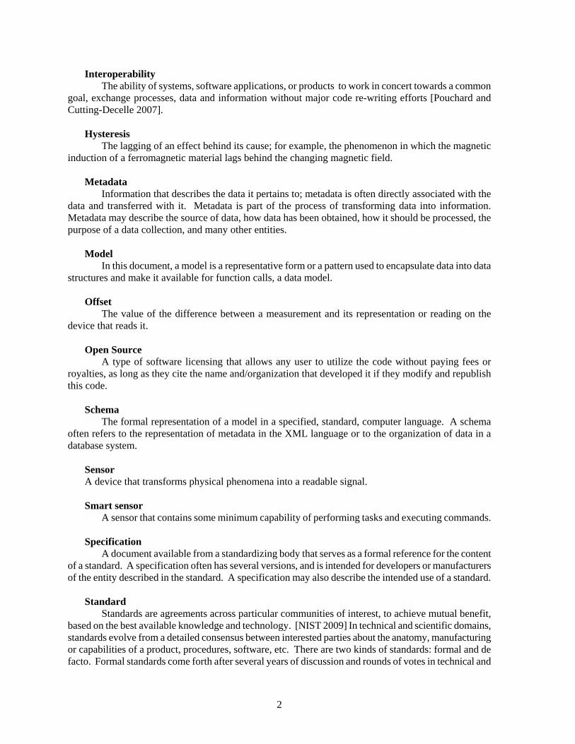
Interoperability The ability of systems, software applications, or products to work in concert towards a common
goal, exchange processes, data and information without major code re-writing efforts [Pouchard and Cutting-Decelle 2007].
Hysteresis The lagging of an effect behind its cause; for example, the phenomenon in which the magnetic
induction of a ferromagnetic material lags behind the changing magnetic field. Metadata Information that describes the data it pertains to; metadata is often directly associated with the
data and transferred with it. Metadata is part of the process of transforming data into information. Metadata may describe the source of data, how data has been obtained, how it should be processed, the purpose of a data collection, and many other entities.
Model In this document, a model is a representative form or a pattern used to encapsulate data into data
structures and make it available for function calls, a data model. Offset The value of the difference between a measurement and its representation or reading on the
device that reads it. Open Source A type of software licensing that allows any user to utilize the code without paying fees or
royalties, as long as they cite the name and/organization that developed it if they modify and republish this code.
Schema The formal representation of a model in a specified, standard, computer language. A schema
often refers to the representation of metadata in the XML language or to the organization of data in a database system.
Sensor A device that transforms physical phenomena into a readable signal. Smart sensor A sensor that contains some minimum capability of performing tasks and executing commands. Specification A document available from a standardizing body that serves as a formal reference for the content
of a standard. A specification often has several versions, and is intended for developers or manufacturers of the entity described in the standard. A specification may also describe the intended use of a standard.
Standard Standards are agreements across particular communities of interest, to achieve mutual benefit,
based on the best available knowledge and technology. [NIST 2009] In technical and scientific domains, standards evolve from a detailed consensus between interested parties about the anatomy, manufacturing or capabilities of a product, procedures, software, etc. There are two kinds of standards: formal and de facto. Formal standards come forth after several years of discussion and rounds of votes in technical and

3
professional organizations, such as the IEEE, and the International Standard Organization (ISO). De facto standards are techniques or methods that emerge with a wide support in industry and science, without approval from a standardizing body or consortium. De facto standards are often formalized later in their life cycle.
Thermistor A type of resistor whose resistance varies with temperature. A temperature sensor useful for
small variations. Transducer A device that converts one type of energy to another usually for measurement purposes.
“Transducer” is commonly used instead of “sensor” and “actuator”. Voltmeter An electronic device that measures the voltage in an electrical circuit, i.e. the difference in
electric potential between two points in the circuit.
3. CONTEXT
Physical facilities hosting computer and data centers have become very large yet still quickly run out of space. The demands in power supply and cooling power required to run HPC at peak performance have become a major factor in the design, operations, and TCO of systems and the facilities that host them. For instance, at the time of this writing, the National Computing and Computational Center at ORNL boasts two floors with 20,000 square feet each, a total electrical capacity of 20MW, and a commensurate amount of chilled water capacity, with three 1200-ton chillers, and two 1500-ton chillers that produce a 42 degree inlet/chilled water supply. The facility hosts many systems. Individual HPC manufacturers have become very aware of these factors, and in response, have made efforts to reduce energy consumption and heat production, while preserving performance. In this context, OEMs have oriented their activities and marketing strategies toward achieving “green computing.”
Green computing is the practice of designing, operating, and generally manages computer resources in an efficient manner. Green computing involves reducing space and power requirements, providing adequate cooling, increasing the efficiency of algorithms, and reduce the costs for disposal and recycling of obsolete equipment. These efforts aim at reducing the TCO, while preserving performance and market edge. This discussion addresses OEMs’ solutions to measure and report heat, voltage, and RPM outputs by instrumenting their platforms with measuring devices such as sensors.
In monitoring the health of HPC systems there is a need to assess the data reported by sensors and the protocols used to report this data. Systems can be instrumented by thousands of sensors. For instance a SyCortex vendor recently mentioned that their latest system has more than 3, 000 sensors. The data can vary greatly, and sometimes appear unreliable. Sensor data can be reported directly by Linux utilities, or captured by system management tools. In a system like Jaguar (Cray XT 4 in the first implementation) that has a total of 7,832 XT4 compute nodes in addition to input/output (I/O) and login service nodes, determining the source of an error and where the problem component is located is non-trivial. Administrators typically use system management tools that tend to be proprietary and not interoperable. When alerts are constantly reported, administrators may distrust or ignore reported errors, or attempt to capture sensor data directly to eliminate one potential source of errors.
However, some government customers in the defense domain are interested in going further and test measurements for accuracy, failure prediction, and to derive application signatures. In cyber-forensics, application physical signatures may be used to detect intrusion or misbehavior.
4
The open source Data Collection and Analysis Tool (DCAT) [Dobson 2008, Pouchard 2009] is being prototyped at ORNL for collecting sensor data and implementing analytics. Another option for testing sensor output would be to simulate the operations processing sensor data. In both cases, non proprietary sensor data models and open source tools are needed to enable data integration, capture, persistence and analysis of sensor data. A suitable standard for sensor data processing will also enable interoperability of future components and future integration of sensor data.
4. EXPLORATION SPACE
Some specifications discussed here are standards developed by various standardizing groups and organizations. Some are simply open source bodies of code and/or documentation and make no claim to standardization. But, they are widely used throughout the HPC community for reporting sensor information, which warrants their inclusion in this report. The following standards and specifications for processing sensor information were evaluated:
• IEEE 1451, sponsored by the National Institute of Standards and Technology. • Sensor Web Enablement, sponsored by the Open Geo-spatial Consortium (OGC). • LM sensors, an open source implementation reporting sensor data, loosely connected to the
Distributed Management Task Force (DMTF). • IPMI: an open source specification sponsored by Dell, HP, NEC, and Intel, implemented in
proprietary tools such as the Baseboard Management Controller. Availability:
• IEEE 1451 specifications are available from IEEE Xplore for a fee. • Sensor ML is available at http://www.opengeospatial.org/standards/sensorml. • Transducer ML resides at http://www.transducerml.org/standards.htm. • LM sensors is at http://www.lm-sensors.org/. • IPMI is located at http://www.intel.com/design/servers/ipmi/.
Future Reference:
• Sensor data solutions from Cray will be studied in the next installment of this report. • IBM InfoSphere and DCAT are being studied as potential homes for data collected from
sensors, and will be part of the next installment.
5. METHOD
In order to evaluate standards and mechanisms for sensor information processing, we procured the specification documents, published papers and other evaluation documents. LM sensors is open source code, which allowed us to inspect it and run it on various platforms. In particular the methods used to configure and implement LM sensors were of interest as they influence the measurements. IPMI has an open source specification, but IPMI tools are proprietary. IPMI sensors and tools are implemented on certain platforms that were available for this report. In this case, IPMI data was collected and stored, but no metric of accuracy is available. Simulations are not part of this report.

5
The rest of the report is organized as follows. After a discussion section (section 6) that summarizes the evaluation of specifications and testing implementations, a conclusion is given in section 7. Each sensor standard and utility is described in details in the Appendix.
6. DISCUSSION
Standardization of data formats, metadata models, and transport protocols enables the leveraging of existing applications, networks, and knowledge as well as comply with future sensors, applications, and architectures.
This study reveals that the existing standards for sensor information processing are not entirely appropriate for HPC needs. The IEEE 1451 and OGC standards are designed to transfer information to a LAN or other local network environment not optimized for HPC. IEEE 1451 permits the remote operation of sensor commands and the specifications are instructions to sensor manufacturers in a wide variety of applications, including electronics, robotics, signal processing, and others, to produce data models and protocols for accessing a network. They are not designed with HPC in mind. TEDS, an important part of IEEE 1451, contains little metadata and is part of the sensor software provided with sensor hardware by manufacturers.
The OGC sensor models permit data and command transmission over the Web, thus using high latency Web protocols. Both IEEE 1451 and SWE sensors produce a significant amount of byte overhead. Sensor ML specifies everything as a process and classifies sensor types according the kind of processes. Sensor ML is complex and extremely rich in metadata with a special emphasis on description of locations due to its origin in the geo-spatial community. Sensor ML contains over 5,000 lines of xml elements available to describe sensor information.
TML has been operational in many domains since 2007. It is a well-documented specification with implementation references. In practice, TML is economical for data transport but contains very little metadata. SensorML is better suited if rich metadata is needed. TML can encode intelligence and defense classification levels in details.
LM sensors, Linux open source software written by Jean Delvare, appear to be the most interoperable and easy-to-use sensor data acquisition tool. Starting with Linux kernel distribution 5, LM sensors are pre-packaged with most distributions. This enables every component of a system instrumented with LM sensors to be tested. LM sensors depend on the Linux community to write drivers for new sensors, which can be slow for new drivers. Drivers are open source and a driver for IPMI is available.
IPMI is a specification that operates at the BIOS level and bypasses the OS layer. It has been designed by a group of PC manufacturers, including HP, Dell, Intel and NEC. Many board and devices manufacturers (but not all) deploy their sensors with IPMI drivers. Coupled with system management tools, IPMI provides a transparent solution to sensor data recording. However, in the absence of open source code or simulation, one is forced to accept OEMs’ claims at face value. If adoption of IPMI becomes more widespread, it may become a de facto “standard,” with limited vendor competition.
Using IPMI log data without a compliant system management tool is painstaking. Attributing proper measurements to the corresponding sensors is a matter of guess work. Little
information is available, difficult to obtain, and provided at the discretion of individual manufacturers. Although IPMI is described in an open source specification, IPMI is implemented in proprietary tools using inaccessible code. Therefore, true validation cannot occur. One round-about way of validating the IPMI implementations would be to run simulations. IPMI is supported by IBM, SuperMicro, AMD and other HPC players but not by Cray who utilizes the Cray RAS and Management System [Becklehimer 2007].

6
7. CONCLUSION
We have studied four mechanisms for reporting embedded sensor data. The report concludes that IEEE 1451 is not suitable because it is mostly aimed at sensor manufacturers and under-specifies the data model. OGC sensor models are designed for the Web, typically ingesting the output of an IEEE 1451 sensor. They are unsuitable for HPC because of the latency involved in Web transactions.
As open source, LM sensors exposes its code and mechanisms for calculations, and does not depend on system vendors. But drivers for new hardware may be slow to develop. Proprietary tools based on IPMI cannot be validated or customized. IPMI is not adopted by some HPC vendors who have developed their own solutions, noticeably Cray.
No single specification or code studied in this report satisfies by itself the goal of providing an open source sensor model suitable to analyze the sensor data provided by all computer manufacturers. IPMI and LM sensors can be used together with LM sensors reporting IPMI data through its IPMI driver, but this does not solve the problem of validating IPMI implementations.
We recommend the development of a compact data model capable of describing sensor data, management data, and performance data. We also recommend the development of an open source generic programming template to enable polling data from multiple, heterogeneous platforms. The template will be serialized and customized to interface each platform, current and future. The data model will be used by the template and for mapping data items into a database. Polling rate, averages, and other calculations will vary.
This data model can be derived from elements of the standards studied below. The Common Interface Management effort contains a sensor data template that is a potential starting point and will be studied in another report.

7
PART II. DETAILED EXPLORATION OF EACH STANDARD AND SCHEMA
1. INTRODUCTION
Sensors are ubiquitous in applications ranging from industrial automation to intelligent transportation systems and homeland security to many others. As sensors are proliferating, it becomes advantageous for sensors to become interoperable with applications and networks. Sensor data, formats and transport need to be harmonized for economies of scale. Efforts strongly pushed forward, in particular at NIST, ORNL, and the University of Alabama, Hunstville, with the results that several standards and tools implementing these standards have emerged and some have become relatively stable (Hu 2007). These standards have been successfully implemented in several large scale projects in agencies and companies such as National Geospatial Intelligence Agency, NASA, Northrop Grumman, ORNL, and the European Space Agency. Sensor data is used in applications such as Homeland Security (SensorNet), geolocation and processing data from satellite and airborn sensors, water monitoring, legacy surveillance sensors, etc.(Lee 2005).
The sensors of interest in this document are networked, that is, they communicate with a server or device to store and use the data. The network connections can be wired or wireless, some sensors also use the Web to disseminate their data. Networks of sensors also need to form larger networks. Some sensors are new technologies while others are legacy devices. All need to pass information to a network, and applications access sensor data for processing. The volume and heterogeneity of data and devices requires open standards in the representation of data, metadata, and other sensor-specific information such as control processes in order to leverage existing applications, networks and knowledge as well as comply with future, unknown applications and networks. The successful adoption of standards results in economies of scale in the development of new tools, sensors, and processing applications.
2. THE IEEE 1451 FAMILY OF STANDARDS.
Section 8 and 9 focus on two families of standards and their interaction: the IEEE 1451 family (IEEE Instrumentation and Measurement Society, 2007) and the Sensor Web Enablement (SWE) developed by the Open Geo-spatial Consortium (OGC). IEEE 1451 (0-X) provides means to interface sensors to networks with the goal of achieving plug-and-play and interoperability. The SWE family provides methods for discovery and control, as well as standard data models. IEEE 1451 enables information transfer between a physical device and a network.
Figure 1. OGC SWE standards serve as an interface between IEEE 1451 and a network.
IEEE 1451
Network
OGC data standards and Web Services (SWE)

8
For the purpose of this report, not all the parts of IEEE 1451 are useful, but a high-level description of the entire standard helps clarify the articulation and interaction between parts. IEEE 1451 and SWE standards are designed to be complimentary and compatible so that the core infrastructure is already in place to achieve this goal.
Throughout this document, the term “sensor” will be used along with “actuator” and “transducer” to represent devices that measure and/or sample quantities over a period of time, and produce digital data to be processed. This is in accordance with the relevant literature and IEEE 1541 notation. 2.1 COMPONENTS
The IEEE standard for Smart Transducer Interface for Sensors and Actuators (IEEE 1451) provides the basis upon which other sensor-related standards such the SWE standards are articulated. IEEE 1451 has two main parts, the Network Capable Application Processor (NCAP) and the Transducer Interface Module (TIM), and an additional component, the Transducer Electronic Datasheets (TEDS) that describes the interaction. Figure 2 illustrates the articulation between parts of IEEE 1451 and external interfaces.
IEEE 1451 is an open standard, independent of platforms and vendors and can be implemented for various communication methods and networks (Lee, 2007). Converting an analog to a digital signal is a vendor task out of the scope of this protocol, but it is facilitated by one part of the IEEE1451 standard. In a generic scenario, upon request from the NCAP (which itself receives it from its applications via network) for sensor data, the TIM provides a digital representation of sensor data formatted according to the data model and format specified in the TEDS for this sensor. NCAP receives the data via one of its implementations, based on the kind of physical connection it shares with the TIM.
For each type of physical communication (PHY), a member of the IEEE 1451.2-X specifies the interface which is implemented by vendors. The TIM and NCAP are complementary in the sense that for each NCAP service, there is a corresponding TIM service. TIM also has additional services, Transducer/Analog Interface, Signal Conditioner, Transducer Measurement Interface, and Transducer Analog Interface, as illustrated in Figure 2. TIM and NCAP are part of the hardware. 2.2 TEDS
Transducer Electronic Data Sheet (TEDS) are generic data structures instantiated with specific information regarding the sensors attached to the TIM and NCAP. Four TEDS are required for all TIMS; other TEDS structures are optional. Over all, TEDS contains little metadata and is part of the sensor software communicated with sensor hardware by manufacturers.
Required TEDS contain:
• Meta-TEDS: some worse timing value communicating to the NCAP when the TIM is deemed timed-out.
• Some information about the relationships between the TransducerChannels that exist in a particular TIM (up to 255).

9
Figure 2. The IEEE 1451 family of sensors, its organization and internal and external connections.
Network Capable Application Processor (NCAP)
NETWORK (Ethernet, Modbus, DeviceNet, ….)
Transducer Interface Module (TIM)
Transducer Electronic Data Sheets (TEDS)
Sensors
Physical Connections (PHY): IEEE 1451.2: Universal Asynchronous Receiver-Transmitter. IEEE 1451.3: Multi-drop Bus. IEEE 1451.5: Wireless Protocols. IEEE 1451.6: CAN Bus connection.
IEEE 1451.0 IEEE 1451.0 (Note: Modbus is a serial communication protocol used in

10
Figure 3. The communication and service stack for the NCAP and TIM modules (courtesy:
IEEE1451.0.2007).
• TransducerChannel TEDS: information about each specific transducer attached to the TIM, such as a physical parameter being measured or controlled, acceptable range of measurements, characteristics of the I/O, the type of digital data used by the transducer (integer or float) and timing information.
• User’s TransducerName TEDS: a place for a user to store the name by which the system knows a sensor.
• PHY TEDS: information about the method of communication between the TIM and NCAP.
Optional TEDS include: • Frequency response TEDS • Calibration TEDS • Transfer function TEDS • Text-based TEDS, including identification. • Command TEDS • Geo-location TEDS.

11
All TEDS share the same generic format illustrated in Table 1.
Table 1. The generic format of a TEDS
TEDS length: Unsigned integer 32, 4 octets.
Payload: binary or text-based, variable length. This data follows the Type Length Value format described below:
Checksum, Unsigned integer 16, 2 octets.
Type: identifies the field in the TEDS contained in the Value field. (See Note). Length: the number of octets in the value field. Value: the data itself.
Note: In the particular case where TEDS data is XML data, this field gives an entry point to different sections of the data carried by this TEDS.
A feature that may be of interest is the possibility of creating Virtual TEDS. TEDS are usually held in memory of the device. In the case of sensors with low capacity, TEDS can be stored in an outside repository, hence become virtual. However, TEDS describe the basic functionality of sensors, but cannot capture the additional descriptions needed by virtual sensors. Nor is TEDS able to describe the higher level of processing required for sensor data. Some OGC standards provide this functionality.
The latest IEEE 1451 specification is 1451.0-2007, which supersedes 1451.1-1999. 1451.2-X describes various methods for communicating with the NCAP and will become compliant with 1451.0 when updated. 2.3 TIM AND NCAP SOFTWARE
In its basic form the TIM software enables TIM to respond to requests from NCAP and initiates its services. The NCAP software must support interaction with TIM and with the external network. API definitions in IEEE1451 are defined such that this software can be implemented in languages like C, as well as in C++ and java, and other, yet unknown, languages.
• TIM and NCAP software support four main features: • TIM discovery queries. • Transducer access request and data properties. • Initiate and respond to transducer management tasks. • Responding and supporting TEDS management functions.
2.4 DATA TYPES
IEEE 1451 uses the following data types for various functions:

12
Table 2. IEEE 1451 Data Types
Unsigned octet integer Unsigned 16 bit integer Signed 32 bit integer Unsigned 32 bit integer Single-precision real Double-precision real String Boolean IEEE1451Dot0::Args::TimeRepresentation formed of two subclasses: TimeDuration and TimeInstance. Two parameters, seconds and nanoseconds. Follows IEEE 1588-2002 (TAI seconds) Physical Units: interpretation, radians, steradians, meters, kilograms, seconds, amperes, kelvins, moles, candelas, Units Extension TEDS access code. Universal unique identification Arbitrary octet array String array Boolean array Array of 8 bit signed integers Array of 16 bit signed integers Array of 32 bit signed integers Array of 8 bit unsigned integers Array of 16 bit unsigned integers Array of 32 bit unsigned integers Array of single-precision real numbers Array of double-precision real numbers Array of TimeDuration data types Array of TimeInstance data types 2.5 COMMANDS
Standard commands and manufacturer-defined commands occupy two octets. The most significant defines the class of command, the least significant defines the specific command within the class.
Standard command classes include:
Commands common to the TIM and Transducer Channel • Transducer idle state • Transducer operating state • Transducer either idle or operating state • Sleep state • Time active state commands • Any state • Reserved.

13
2.6 COMMUNICATION BETWEEN NCAP AND THE NETWORK
As illustrated in Figure 1, one function of the NCAP is to provide an interface between IEEE 1451 and a network. Network specifications are out of scope for IEEE 1451, and thus not specified in IEEE 1451. However, several examples of network implementations are proposed. The Smart Transducer Object Model, http, and SWE are of interest to this project. SWE will be discussed in section 9. The Smart Transducer Object Model is a generic model described in IEEE 1451.1-1997, an archived standard superseded by IEEE 1451.0 discussed here. As IEEE 1451.0 does not specify a new Object Model, one must use IEEE 1451.1-1997 in cases where http and SWE are not appropriate. 2.7 HTTP APIS
IEEE 1451 communication to a network can be described using the http client-server paradigm with NCAP representing the server that provides sensor-related data to a client located on a network. The client is any application requesting sensor data from the NCAP. For instance, the ORNL DCAT software could request sensor data from NCAP (Figure 3).
Figure 4. NCAP/Application communication via http.
IEEE 1451.0 proposes APIs for communication between NCAT and the Internet via the HTTP 1.1
protocol. These implementations use the GET and POST methods and focus mainly on accessing Transducer data and TEDS: GET can be used to read and write transducer data and transducer TEDS; POST can be used to take a command or change the state of a resource. The http message format follows the usual format:
http://<host>:<port>/<path>?<parameters>
• Four http APIs are proposed: • Discovery API • Transducer Access API • Transducer Manager API. • TEDS Manager API
The data formats used by the responses of these APIs include text, html, and xml. In the case of an
application requesting sensor data to be returned in XML, XML schemas are defined, with one schema for each type of query or function call (29 total) available at: http://grouper.ieee.org/groups/1451/0/1451HTTPAPI/
HTTP Response
HTTP Request
DCAT
NCAP
HTTP ServerIEEE 1451.0IEEE 1451.x

14
3. OPEN GEO-SPATIAL CONSORTIUM (OGC)
SENSOR WEB ENABLEMENT (SWE) STANDARDS
The ongoing SWE efforts carried out by OGC are designed to provide methods for discovering sensors and accessing sensor data, obtaining sensor information, tasking sensors and receiving alerts. SWE standards describe sensor location, observed variables, the ability to task, sensor description, and data fields for sensor networks that use the Web as a means for distributing sensor data to applications. Before the development of SWE, Web applications using sensor data had no guaranty of interoperability with other web-enabled sensors or future sensors. Neither was there a way to discover and control sensors on a network.
OGC is an international consortium of companies, government agencies and universities. Stakeholders instrumental in the development and deployment of SWE include ORNL (SensorNet), NASA, the European Space Agency, intelligence agencies, defense contractors, and many others.
The SWE standards provide a bridge between IEEE 1451 and a network accessing the Web. While, in principle, any type of sensor data can interact with any sensor infrastructure using IEEE 1451, the SWE initiative focuses on sensors accessing the Web. As illustrated in figure 1, SWE interacts with the Network Capable Application Processor (NCAP) in IEEE 1451. SWE standards comprise data encodings and a suite of Web services capable of performing user- or machine-required tasks on the sensors. Within SWE, all sensors report position, are connected to the Web and readable remotely, and able to report position and register metadata. Some sensors are also controllable remotely. Figure 4 presents the SWE vision.
Figure 5. The vision of SWE (courtesy Sheth, 2008).
We focus first on the data models in SWE: SensorML, TransducerML and Observations and Measures (O & M). SensorML and TransducerML describe sensor characteristics, including data transforms. O & M describe sensor data.
3.1 SENSOR ML
In this paper we refer to the most recent schema as described in Sensor ML 1.0.1 (2008) (OGC). SensorML is a mark-up language (ML) derived from XML for describing sensor processes, including sensor tasking, location of sensor observations, and processing of low-level sensor observations.

15
SensorML describes sensor systems, processing algorithms and workflows and can encode the on-demand execution of algorithms for remotely controlling sensors. The “process” is the main concept underlying SensorML. Detectors, actuators, and sensors are all described in terms of processes. Within SensorML, a sensor is a process that converts real phenomena into data (Botts, et al., 2008).
Processes are divided along four orthogonal dimensions: Atomic or Composite, Physical or Non-physical processes (Figure 5). All SensorML processes have common characteristics such as inputs, outputs, parameters (defined using SWE Common data) and metadata serving primarily for discovery purposes. The type of process determines additional, not shared characteristics. Atomic Processors, whether physical or non-physical also have Process Methods.
Figure 6. Topology of processes in SensorML (courtesy: Botts, 2008).
Atomic Processes
Composite Processes
Physical Processes
Non‐physical Processes
Examples: detectors, actuators, data readers, writers, access services, human
analysts…
Examples: Spatial transforms,
derivable information…
Examples: Observation lineage
(provenance), executable, on‐demand process
chains…
Examples: Sensor systems, platforms…
16
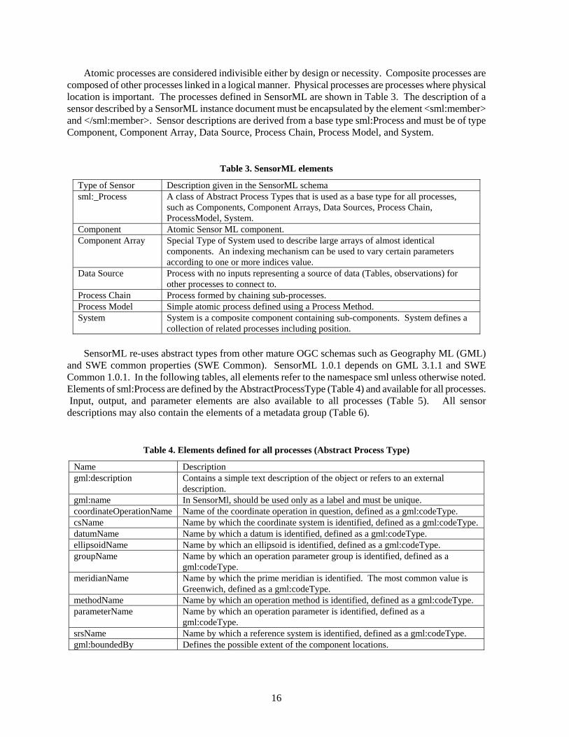
Atomic processes are considered indivisible either by design or necessity. Composite processes are composed of other processes linked in a logical manner. Physical processes are processes where physical location is important. The processes defined in SensorML are shown in Table 3. The description of a sensor described by a SensorML instance document must be encapsulated by the element <sml:member> and </sml:member>. Sensor descriptions are derived from a base type sml:Process and must be of type Component, Component Array, Data Source, Process Chain, Process Model, and System.
Table 3. SensorML elements
Type of Sensor Description given in the SensorML schema sml:_Process A class of Abstract Process Types that is used as a base type for all processes,
such as Components, Component Arrays, Data Sources, Process Chain, ProcessModel, System.
Component Atomic Sensor ML component. Component Array Special Type of System used to describe large arrays of almost identical
components. An indexing mechanism can be used to vary certain parameters according to one or more indices value.
Data Source Process with no inputs representing a source of data (Tables, observations) for other processes to connect to.
Process Chain Process formed by chaining sub-processes. Process Model Simple atomic process defined using a Process Method. System System is a composite component containing sub-components. System defines a
collection of related processes including position.
SensorML re-uses abstract types from other mature OGC schemas such as Geography ML (GML) and SWE common properties (SWE Common). SensorML 1.0.1 depends on GML 3.1.1 and SWE Common 1.0.1. In the following tables, all elements refer to the namespace sml unless otherwise noted. Elements of sml:Process are defined by the AbstractProcessType (Table 4) and available for all processes. Input, output, and parameter elements are also available to all processes (Table 5). All sensor descriptions may also contain the elements of a metadata group (Table 6).
Table 4. Elements defined for all processes (Abstract Process Type)
Name Description gml:description Contains a simple text description of the object or refers to an external
description. gml:name In SensorMl, should be used only as a label and must be unique. coordinateOperationName Name of the coordinate operation in question, defined as a gml:codeType. csName Name by which the coordinate system is identified, defined as a gml:codeType. datumName Name by which a datum is identified, defined as a gml:codeType. ellipsoidName Name by which an ellipsoid is identified, defined as a gml:codeType. groupName Name by which an operation parameter group is identified, defined as a
gml:codeType. meridianName Name by which the prime meridian is identified. The most common value is
Greenwich, defined as a gml:codeType. methodName Name by which an operation method is identified, defined as a gml:codeType. parameterName Name by which an operation parameter is identified, defined as a
gml:codeType. srsName Name by which a reference system is identified, defined as a gml:codeType. gml:boundedBy Defines the possible extent of the component locations.

17
Table 5 illustrates the elements available to all processes to describe inputs, outputs, and parameters.
Table 5. Elements for input and output signals, and parameters
Name Description swe:Count Integer for counting a value swe:Quantity Decimal with optional unit and constraints swe:Time Either ISO 8601 or time relative to an origin. swe:Boolean True or False swe:Category Identifies the name of a category, should provide dictionary entry for a
useful interpretation. swe:Text Free text swe:QuantityRange Decimal pair for specifying a quantity range with constraints. swe:CountRange Integer pair for specifying a quantity range with constraints. swe:TimeRange Time value pair specifying a time range. swe:ConditionalData List of conditional values for a property. swe:Conditional Value Qualifies data with one or more conditions. swe:DataRecord Implementation of ISO-11404 Record Data Type. swe:Envelope Typically used to define rectangular bounding boxes in any coordinate
system. swe:GeoLocationArea Area used to define bounding boxes. swe:NormalizedCurve swe:Position Position given as a group of vectors/matrices. swe:SimpleDataRecord Implementation of ISO-11404 Record Data type. swe:Vector The Vector has a reference frame in which the coordinates are expressed.

18
SensorML metadata is intended for describing provenance and discovery information rather than execution of processes (Botts, 2007). The metadata elements are shown in Table 6. All elements in the metadata group are optional. However, if used, they must contain the required elements from the third column.
Table 6. SensorML elements in the metadata group
Element Name Description Required element(s) sml:keywords Provides a list of keywords for quick
discovery KeywordList keyword
sml:identification Provides various identity and alias values, such as shortName, longName, modelNumber, whose terms can be defined in an online dictionary such as urn:x-ogc:def:identifier:OGC
IdentifierList identifier:Term
sml:classification Specify classification values with types such as sensorType, intendedApplication, etc. Classification values can be found in an online dictionary.
ClassifierList classifier
sml:validTime Time validity constraint of description. Uses gml type.
gml:TimeInstant gml:TimePeriod
sml:securityConstraint Provides security constraints of description. Uses sweCommon type.
Security
sml:legalConstraint Provides legal constraint of description. Sml specific.
Rights
sml:characteristics Characteristic list for quick discovery, e.g. Conditional Data, data record, Geolocation area, normalized curve, position, vector. Sml specific.
swe:AbstractDataRecord
sml:capabilities Capability list for quick discovery. swe:AbstractDataRecord sml:contact Relevant contacts for that object. Person
ResponsibleParty ContactList
sml:documentation Relevant documentation for that object. history History of the object described, given in an
Event list (recalibration, adjustments, etc.). EventList

19
In addition to the elements defined for all processes with the Abstract Type sml:Process, the common elements defined for inputs, outputs, parameters, and the metadata elements, processes also use additional elements, depending on where they are located in Figure 3. Atomic and Composite physical processes contain elements for encoding location. These elements include Spatial Reference, Temporal Reference, BoundedBy, Position, and Interface Definition. Composite processes contain a list of components and a connection link between components. Component and Process Model contain an element for Process Method. Table 7 illustrates the specific elements available to each type of process that distinguish them from other processes.
Table 7. Elements specific to each process type
Process Type Specific Elements Description ProcessMethod: rules
Text or language defining rules for process profile
ProcessMethod:algorithm Textual or MathML description of the algorithm.
Component, Process Model
ProcessMethod:implementation Reference implementation in the specified programming language (can be a sensorML Process Chain).
dataDefinition DataBlockDefinition DataStreamDefinition
values
DataSource
observationReference components Collection of processes that can be
chained using connections. positions Relative positions of the system
components.
System, ComponentArray
connections Provides links between processes or between processes and data sources.
ProcessChain components, connections Defined above.
SWE standards also define several types of Web Services to interact with sensors defined with the data models described above. Several of these specifications are only “best practices” documents, the highest level of acceptance before becoming a standard in OGC. The next section briefly reviews these services. 3.2 SWE WEB SERVICES
Sensor Observation Services (SOS) and Sensor Planning Service (SPS) are both OGC accepted standards. SOS is a standard Web service interface for requesting, filtering, and retrieving observations and sensor system information. A client requesting sensor data from an observation repository or a real-time channel may use SOS to connect to the repository and download data. SPS is a Web service for requesting user-driven acquisitions and observations (Botts, et al., 2008)
The Sensor Alert Service (SAS) and the Web Notification Services (WNS) are both best practices documents at the time of this writing. SAS is intended for publishing and subscribing to alerts from sensors. WNS is an interface for the asynchronous delivery of messages or alerts from SAS and SPS.

20
3.3 TRANSDUCER ML
The TransducerML (TML) effort was originally supported by the Air Force and National Geospatial Agency and has become one of the SWE suite of standards April 10, 2007. TML provides a communication and presentation layer protocol for streaming sensor data (live or archived) and exchange data between sensors. Sensors are often organized in sensor systems or in classes of sensors that may include all types of sensors, including receivers, transmitters, transducers, actuators and processes. The data measured by such sensors may include images, temperatures, etc. and can be used for intelligence applications, signal surveillance and reconnaissance. TML is capable of handling such systems without prior knowledge and can exchange information between classes and systems of sensors.
TML exchanges data and instructions on how to handle the data in the same data package and uses some common OGC models. TML includes information about how to exchange the associated data with any TML processes. TML is adaptable, scalable and supports data fusion between sensor systems (for example fusion of weather and marine data). Because a TML instance can carry information about groups of sensor data, as well as their spatio-temporal interrelationships, TML is more economical than SensorML for large numbers of small, related data files.
In order to support dynamic streaming of data, a task for which XML is not very suited, TML provides an XML envelope designed for efficient transport of live sensor data in groupings known as TML clusters. TML provides clock synchronization mechanisms that allow comparison between streams from different sensors along a single timeline. It also supports precise spatial alignment between elements, thus allowing applications to reconstruct or interleave data streams for fusion and cueing.
TML can also encode details about intelligence and defense classification levels deriving element from the unique resource “urn:us:gov:ic:ism:v2” and the schema “IC-ISM-v2.xsd.” The TML namespace is: xmlns:tml=http://www.opengis.net/tml.
TML is a well-documented specification, with implementation references, and is operational in many domains. In practice, TML is economical for data transport but contains very little regarding metadata. SensorML is better suited if rich metadata is needed, and is quite complex.
4. LM-SENSORS
Linux Monitoring (LM sensors) is a hardware-monitoring effort to measure and report the health of Linux systems that contain the supported hardware chips. LM sensors consist of some general libraries and hardware-specific packages (see Appendix X for supported hardware at the time of this writing). Users, logged in as Administrators, may run the sensors-detect utility to determine which sensors, if any, are available for monitoring on their system. Starting with the Linux 2.6 release LM sensors should be included in the kernel. Most modern motherboards incorporate some form of hardware monitoring chips that read quantities like chip temperatures, fan rotation speeds and voltage levels. According to LM sensors developers, laptops rarely expose their hardware with the result that LM sensors typically report temperatures only.

21
The following tables provide example readings for an HP laptop outfitted with two Intel 2 Core T 7600 CPUs running at 2.33 GHz with 2 GB RAM. This laptop runs rhel Linux version 2.6.18-92.1.13.el5. In this author’s experience, the Linux kernel had to be re-compiled to include monitoring components.
Table 8 illustrates an example of a sensors-detect log. Table 9 illustrates the results of the monitoring scan.
Table 8. Results of sensors-detect for reefcreature.ornl.gov
Probing for (PCI) I2C or SMBus adapters on reefcreature Probing for PCI bus adapters... Sorry, no supported PCI bus adapters found Scanning the ISA I/O ports National Semiconductor LM78' at 0x290... No National Semiconductor LM78' at 0x290... No National Semiconductor LM79' at 0x290... No Winbond W83781D' at 0x290... No Winbond W83782D' at 0x290... No IPMI BMC KCS' at 0xca0... No IPMI BMC SMIC' at 0xca8... No Scanning for Super I/O sensors Super-I/O at 0x2e/0x2f (family `SMSC') Found unknown chip with ID 0x2600 Super-I/O at 0x4e/0x4f (family `SMSC') Found unknown non-standard chip with ID 0x7a Scanning for south bridges, CPUs or memory controllers Intel Core family thermal sensor... Success: driver coretemp * Chip Intel Core family thermal sensor Detects correctly (confidence 9)
Table 9. Scanning results for reefcreature
coretemp-isa-0001
+51.0 C high = +100.0 C, crit = +100.0 C
coretemp-isa-0000
+51.0 C high = +100.0 C, crit = +100.0 C
Sensors were detected by LM sensors on a desktop running Ubuntu 8.04 (32-bit) with Linux kernel version 2.6.27.5.

22
Table 10 illustrates the results of the scan for this system:
Table 10.Scanning results for desktop running Ubuntu
Lm version lm85-i2c-0-2e Adapter SMBus I801
adapter at 3000
Voltage: V1.5 +1.25 V min = +1.42 V, max = +1.58 V ALARM Voltage: V core +1.28 V min = +1.18 V, max = +1.45 V ALARM Voltage: V 3.3 +3.32 V min = +3.13 V, max = +3.47 V Voltage: V 5 +5.10 V min = +4.74 V, max = +5.26 V Voltage: V 12 +12.12 V min = +11.38 V, max = +12.62 V CPU Fan 1687 RPM min = 900 RPM Front Fan 3 661 RPM min = 0 RPM Rear Fan 4 330 RPM min = 0 RPM CPU temperature + 57.0 C low = + 10.0 C, high = + 65.0 C Board temperature + 40.0 C low = + 10.0 C, high = + 45.0 C Remote + 43.0 C low = + 10.0 C, high = + 45.0 C CPU0_vid + 1.538 V coretemp-isa-0000 (ISA adapter)
+73.0 C high = + 84.0 C, crit = + 100.0 C
coretemp-isa-0001 (ISA adapter)
+74.0 C high = + 84.0 C, crit = + 100.0 C
Tests using LM sensors were also performed for testbed machines pod1 and pid1. Pod1 consists of a
quad core AMD Opteron 8350, Supermicro H8QM3 motherboard, and 32 GB RAM. Pid1 consists of a dual core Intel Xeon 5150, Supermicro X7DWA, and 16 GB RAM.
A temperature result of -48F indicates that the temperature input is not connected. A fan rpm of zero indicates that the system may not have a three-wire fan, which is required. A two-wire fan cannot report on its rpm. LM-sensors require careful configuration if comparisons between systems are made. Manufacturers do not calculate measurements in the same way. Sensors are sometimes embedded directly in the chip, rather than next to it on the motherboard.

23
The results of these tests are reported in Tables 11 and 12.
Table 11. LM sensors run on PID 1 and a winbond Super I/O chip: w83627hf-isa-0290
Adapter: ISA adapter VCore 1: +3.90 V (min = +1.34 V, max = +1.49 V) ALARM VCore 2: +3.79 V (min = +1.34 V, max = +1.49 V) ALARM +3.3V: +3.82 V (min = +3.14 V, max = +3.46 V) ALARM +5V: +5.27 V (min = +4.73 V, max = +5.24 V) ALARM +12V: +11.67 V (min = +10.82 V, max = +13.19 V) -12V: +0.88 V (min = -13.18 V, max = -10.88 V) ALARM -5V: +1.89 V (min = -5.25 V, max = -4.75 V) ALARM V5SB: +5.59 V (min = +4.73 V, max = +5.24 V) ALARM VBat: +0.08 V (min = +2.40 V, max = +3.60 V) ALARM fan1: 0 RPM (min = 0 RPM, div = 2) fan2: 0 RPM (min = 0 RPM, div = 2) fan3: 0 RPM (min = 0 RPM, div = 2) temp1: -48°C (high = -79°C, hyst = +22°C) sensor = thermistor temp2: -48.0°C (high = +80°C, hyst = +75°C) sensor = thermistor temp3: -48.0°C (high = +80°C, hyst = +75°C) sensor = thermistor vid: +1.419 V (VRM Version 11.0) alarms: beep_enable Sound alarm enabled
Table 12. LM sensors run on POD 1 and a winbond Super I/O chip: w83627hf-isa-0290
Adapter: ISA adapter VCore 1: +3.90 V (min = +1.34 V, max = +1.49 V) ALARM VCore 2: +3.79 V (min = +1.34 V, max = +1.49 V) ALARM +3.3V: +3.82 V (min = +3.14 V, max = +3.46 V) ALARM +5V: +5.27 V (min = +4.73 V, max = +5.24 V) ALARM +12V: +11.67 V (min = +10.82 V, max = +13.19 V) -12V: +0.88 V (min = -13.18 V, max = -10.88 V) ALARM -5V: +1.89 V (min = -5.25 V, max = -4.75 V) ALARM V5SB: +5.59 V (min = +4.73 V, max = +5.24 V) ALARM VBat: +0.08 V (min = +2.40 V, max = +3.60 V) ALARM fan1: 0 RPM (min = 0 RPM, div = 2) fan2: 0 RPM (min = 0 RPM, div = 2) fan3: 0 RPM (min = 0 RPM, div = 2) temp1: -48°C (high = -79°C, hyst = +22°C) sensor = thermistor temp2: -48.0°C (high = +80°C, hyst = +75°C) sensor = thermistor temp3: -48.0°C (high = +80°C, hyst = +75°C) sensor = thermistor vid: +1.419 V (VRM Version 11. 0) alarms: beep_enable Sound alarm enabled
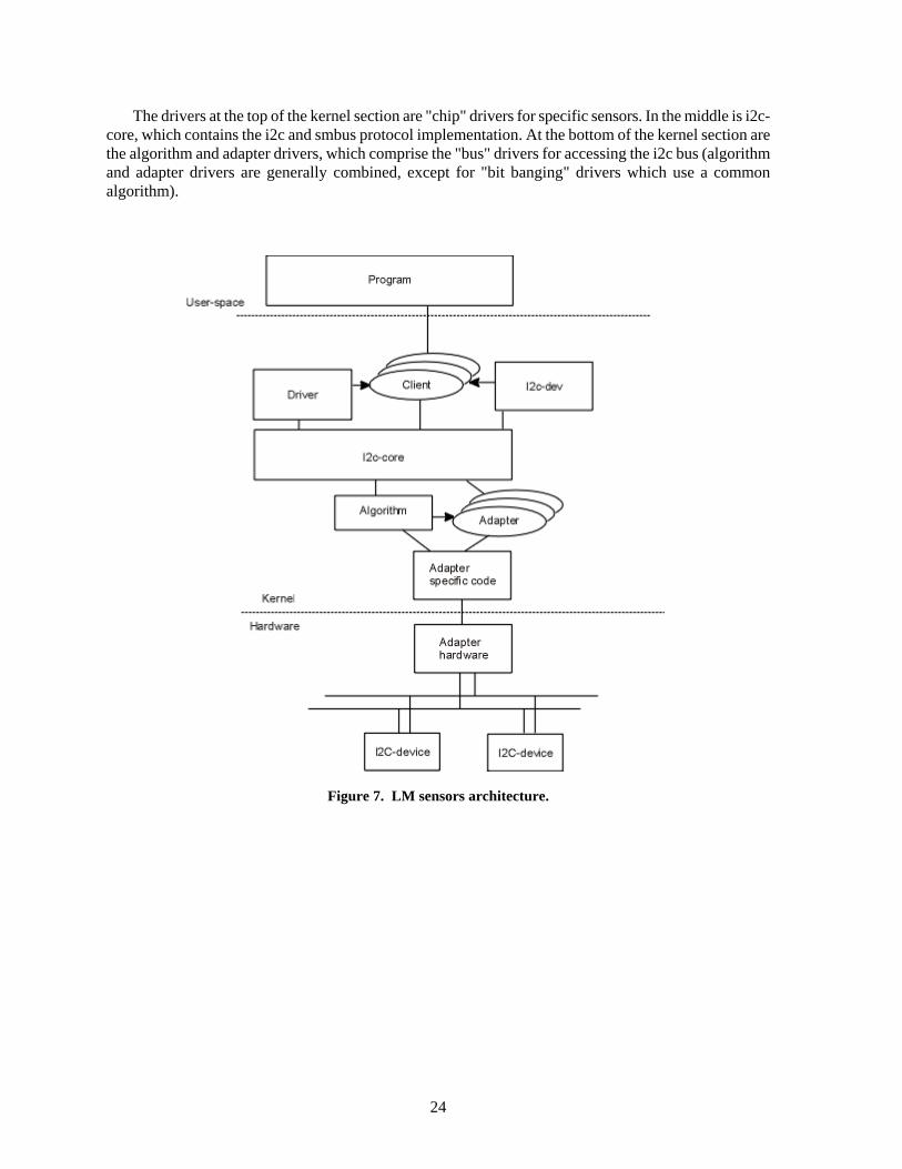
The architecture and kernel modules used by LM sensors is illustrated in Figure 7 (courtesy of [email protected], LM sensors wiki). In the figure, the "program" section at the top represents the lm_sensors user programs, including "sensors", "sensors-detect", "i2cdetect", and "isadump."
24
The drivers at the top of the kernel section are "chip" drivers for specific sensors. In the middle is i2c-core, which contains the i2c and smbus protocol implementation. At the bottom of the kernel section are the algorithm and adapter drivers, which comprise the "bus" drivers for accessing the i2c bus (algorithm and adapter drivers are generally combined, except for "bit banging" drivers which use a common algorithm).
Figure 7. LM sensors architecture.
25
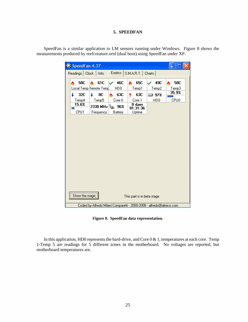
5. SPEEDFAN
SpeedFan is a similar application to LM sensors running under Windows. Figure 8 shows the measurements produced by reefcreature.ornl (dual boot) using SpeedFan under XP.
Figure 8. SpeedFan data representation.
In this application, HD0 represents the hard-drive, and Core 0 & 1, temperatures at each core. Temp
1-Temp 5 are readings for 5 different zones in the motherboard. No voltages are reported, but motherboard temperatures are.

26
6. APPLICATIONS FOR SENSOR-BASED MONITORING OF MAC OS X SYSTEMS:
Hardware monitoring applications are also available for Mac OSX. Table 13 shows example results for the Hardware Monitor application [Bresink, 2009].
Table 13: Hardware monitoring for Mac OS Sensor Value Unit Ambient Air 24 CPU A Temperature Diode
37
Graphics Processor Temperature Diode 53 Hard Drive Bay 1 38 Memory Controller 40 Optical Drive 33 SMART Disk ST3160812AS Q (9LS026NS) 42 CPU Core 1 33 CPU Core 2 34 CPU A 1.00513 V Graphics Processor Supply 1 0.995239 V CPU A 31.7563 A Graphics Processor Supply 1 2.17383 A CPU A 2.1891 W Graphics Processor Supply 1 2.16016 W CPU Fan 997 RPM Fan Hard Drive 1199 RPM Fan Optical Disk Drive 998 RPM Ambient Light 1 7 Graphics Processor 4 % CPU Clock Frequency 2000.04 MHz

27
7. INTELLIGENT PLATFORM MANAGEMENT INTERFACE (IPMI) SPECIFICATION
The IPMI specification provides a way to represent and exchange computer information between a control application and clients to facilitate the intelligent management of multiple computers in a remote setting. Intelligent Platform Management refers to autonomous monitoring and recovery features embedded into platform management hardware and software. The inventory, monitoring, logging and recovery functions are accessible independently of BIOS and operating systems. IPMI is supported by Intel, HP, Dell and NEC, and addresses the computer management of enterprise systems.
As each OEM integrates different sensors for motherboards, chassis, and chips, managing a cluster of systems or servers, each with a different hardware configuration, is a daunting task. IPMI proposes a solution to heterogeneous platform instrumentation by implementing a standard interface for data, transport, and communication messages for each device on a bus, an SMbus, or a PCI bus. For inventory, monitoring and recovery features, IPMI enables interoperability between chassis and baseboard, chassis, baseboard and management application, and between servers (See Figure 9).
Figure 9. IPMI in a managed platform.
Server
Server
System Management Tool
Legend: IPMI connections
Server
Baseboard Sensor
Chassis Sensor
Chip Sensor

28
IPMI is described as highly available, that is, its independence from BIOS, OS, and sensors allows for a server to be accessed remotely, including when a machine is not running. IPMI also allows for starting or shutting down a machine remotely. 7.1 ARCHITECTURE: BOARD CONTROLLER, BUS, MESSAGING
IPMI’s main components are a Baseboard Management Controller (BMC) at the core of the architecture, an IPM Bus, IPMI messaging, system event logs and event messages, and a sensor model (See Figure 10).
The BMC is a microcontroller that manages the interfaces between System Management tools, platform hardware, instrumentation, additional remote controllers and private management busses if needed. The IPM Bus is an I2C-based serial bus that connects sensors, chassis, motherboard, auxiliary remote management hardware, bridges to other chassis, to the system interface. The IPM Bus transports IPMI messages consisting of a core structure with identical format fields for the payload in each message, wrapped by various envelopes depending on the transport mechanisms.
Figure 10. IPMI connection diagram.
Baseboard Management Controller (BMC)
Auxiliary/Bridge
Chassis Management
Sensors
System interface
System Management Tool
IPMI Messages
IPMI Messages
IPMI Messages
LEGEND IPM Bus System Bus

29
7.2 SENSOR DEVICE COMMANDS AND EVENT READINGS
Sensor devices are devices that send commands to an individual or a group of sensors. Monitored information is accessed via abstracted sensor device commands (See table 14) rather than
directly from the hardware. IPMI accommodates static sensor devices, configured in the system at manufacturing, and dynamic
sensor devices, responding to a broadcast discovery message by the IPMB. IPMI distinguishes linear (or linearized) and non-linear sensors. Linear and linearized sensors are
assumed to have constant Accuracy, Tolerance, and Resolution over the range of their raw measurements. These sensors rely on a linear conversion formula to obtain the desired unit/value from raw measurement. Non-linear sensors do not have constant Accuracy, Tolerance, and Resolution over the range of measurements. As a result, the desired unit/value is obtained by applying a conversion formula that varies with the raw reading and is obtained with the Get Sensor Reading Factor command.
Table 14. Sensor Device Commands
Command (domain) Applies to (range) Performs (property) Get Device SDR Info Dynamic Sensor Devices Gets sensor information. Get Device SDR Sensor Devices in a satellite Management
Controller Gets sensor information.
Reserve Device SDR Repository
Sensors with readings that may changes during a multi-part reading.
Obtains a reservation ID for a record in SDR repository.
Get Sensor Reading Factors
Non-linear Sensors Obtains the conversion factor for a particular reading.
Set Sensor Hysteresis1 Sensors with threshold-based event generation
Set hysteresis value for all thresholds.
Get Sensor Hysteresis Sensors with threshold-based event generation
Retrieves present hysteresis value.
Set Sensor Threshold Threshold-based sensors Sets Threshold. Get Sensor Threshold Threshold-based sensors Retrieves threshold. Set Sensor Event Enable Individual sensor events Enables or disables Event message
generation. Get sensor Event Enable Individual sensor events Returns the enabled/disabled state for
a sensor. Re-arm Sensor Event Threshold-based sensors Reset thresholds on sensors requiring
this task. Also used as a request to update or recheck a reading.
Get Sensor Event Status Systems where sensor polling is used, instead of, or in addition to, Event Messages
State gets updated when the controller detects a state change or a transition.
Get Sensor Reading Any sensor Returns the present reading: either a stored value or request a reading and returns it.
Set Sensor Type Sensor Type and Event/Reading Type Assigns types to a particular sensor, may be done at manufacturing.
Get Sensor Type Any sensor that responds to the Set Sensor Type command.
Retrieves the Sensor Type and/or Event Type.
IPMI also distinguishes discrete vs. threshold-based sensors. Discrete sensors can report up-to-fifteen
possible states (Generic or Sensor-specific). Discrete sensors are further divided into “digital” and “OEM” where “digital” is a discrete sensor that only has two possible states. “OEM” sensors are special sensors where the offsets are specified by its manufacturers (OEM).

30
IPMI can trigger Event\Reading type of information to be reported to the BMC. IPMI can report both sensor readings and sensor-offsets, and interpret the information to report a particular state. Each command and its possible outcomes are listed in the IPMI specification along with corresponding hexadecimal code. 7.3 SENSOR DATA RECORDS (SDRS)
SDRs are basic units for recording each event and sensor type. SDRs are containers of information about a sensor, allowing an existing sensor to describe itself. They also contain the information or event being read. SDRs do not instantiate a new sensor and creating a new sensor record will not start readings.
There are twelve possible kinds of records, attempting to cover all scenarios and combinations of sensor type and event type. They include:
• Full record, • Compact record, • Event-only record, • Device locator records, • others.
The format for an SDR is: • [Record header][Record key field][Record body]: • [Record header] includes ID, version, type of record, byte length. • [Record key] a unique combination of fields used for retrieving the record (needed since IDs
may be re-assigned). • [Record body] the information within a record. Table 15 shows the information an SDR may contain.
Table 15. Information provided in SDRs
Type of sensors in the platform Number of sensors in the platform Sensor threshold support Even generation capabilities Information on the types of reading provided by the sensor Number of devices connected to an IPMBus Type of devices connected to an IPMBus Location of FRU devices Type of FRU devices Information being reported (Event, reading)
FRU devices provide FRU information such as serial number for FRU inventory purposes. SDRs are presented in hexadecimal notation, both for the record header and for the record body.
Tables in the IPMI specification specify a code for each type of information reported. An SDR is a suite of hex codes in the appropriate bin (Byte place). In practice, one must rely upon proprietary IPMI tools as an interface to system management software in order to obtain useful information.

31
Example: For example, we take an SDR describing temperature and voltage sensors for a power supply. Our
temperature and voltage sensors are discrete sensors generating generic events/readings. They can return severity-related events (Event/Reading offsets) such as Transition from OK to Non-critical, from Less Severe to Critical, and other states.
An SDR for the temperature and voltage sensors will contain information at the following places: • Byte 4: 02h. (Compact SDR format). • Byte 9: 0Ah (Monitors an entity of the type Power supply). • Byte 13: 01h (Sensor type: Temperature). • Byte 13: 02h (Sensor type: Voltage). • Byte 14: 07h (Generic Event/Reading Type: Discrete sensor). • Byte 15: 01h, 02h, etc… (potential Generic Event/Reading offsets). • Byte 21: 11b (Sensor unit polling rate: second). • Byte 22: 1 (Sensor unit: Degree Celsius). • Byte 22: 4 (Sensor Unit: Voltage).

32
8. REFERENCES
Becklehimer, Jeffrey, Cathy Willis, Josh Lothian, et al. Real Time Health Monitoring of the Cray XT3/XT4 Using the Simple Event Correlator. Proceedings of the Cray User Group (CUG 2007).
Botts, Mike, Carl Reed, George Percivall, John Davidson. OGC Sensor Web Enablement: Overview and High Level Architecture. Proceedings of the 5th International Information Systems for Crisis Response and Management (ISCRAM) Conference. F. Friedrich and B. Van de Walle, eds. Washington, DC: May 2008.
Botts, Mike. SensorModel Language (SEnsorML) Details. Earth System Science Center, UAB Huntsville. September 2007. http://schemas.opengis.net/sensorML/.
Brezink, Marcel. Hardware Monitor for MacOSX. Available from: http://www.bresink.de.
Dobson, J. and L. Pouchard. Providing the Foundation for the Analysis of Large Data Sets and a Framework for Network Analysis. DOE Science Undergraduate Laboratory Internship poster session. Oak Ridge, TN: July 2008.
Hsu, Chung-hsing and Wu-chun Feng. A Power-aware Run-time system for High Performance Computing. Proceedings of SC05, Seattle, WA: November 12-18, 2005.
Hsu, Chung-hsing and Wu-chun Feng. A Power-aware Run-time system for High Performance Computing. Proceedings of SC05, Seattle, WA: November 12-18, 2005.
Hu, Peizhao, Ricky Robinson, Jadwiga Indulska, “Sensor Standards: Overview and Experiences,” Proceedings of the Third International Conference on Intelligent Sensors, Sensor Networks and Information. (ISSNIP) Dec. 3-6, 2007. 485-490.
IEEE Instrumentation and Measurement Society. Technical Committee on Sensor Technology (TC-9). IEEE Standard for a Smart Transducer Interface for Sensors and Actuators – Common Functions, Communication Protocols, and Transducer Electronic Data Sheet (TEDS) Formats (IEEE1451.0.2007).
IPMI - Intelligent Platform Management Interface Specification Second Generation V2.0. Document Revision 1.0. February 12, 2004. Available from http://www.intel.com/design/servers/ipmi/.
Lee, Kang. Open Standards for Homeland Security Sensor Networks. IEEE Instrumentation and Measurement Magazine, December 2005.
Lee, Kang. Sensor Standards Harmonization – Path to Achieving Sensor Interoperability. Proceedings of the Autotestcon, Sept. 17-20, 2007.
LM sensors. http://www.lm-sensors.org/wiki and http://www.lm-sensors.org/wiki/Documentation.
National Institute of Technology Ontology Summit 2009 Communique: Towards Ontology-based Standards. Available from: http://ontolog.cim3.net/cgi-bin/wiki.pl?OntologySummit2009_Communique.
Open Geo-spatial Consortium. SensorML 1.0.1. Available from http://schemas.opengis.net.
[Pouchard 2009] L.C. Pouchard, J.D. Dobson, J.P. Trien, “A Systematic Framework for the Collection of Open Source Intelligence,” Techno-social Predictive Analytics Initiative. AAAI Spring Symposium, Stanford, CA, March 2009.
Pouchard, Line C. and Anne-Francoise Cutting-Decelle. Ontologies and standards-based approaches to interoperability for Concurrent Engineering. Book Chapter. Concurrent Engineering in Construction Projects. Chimay Anumba, John Kamara, Anne-Francoise Cutting-Decelle, eds. P.118-161. London and New York: Taylor and Francis, 2007.

33
Sheth, A. P. Semantic Sensor Web. ARC Research Network on Intelligent Sensors, Sensor Networks and Information Processing (ISSNIP) presentation. Melbourne, August 1, 2008.
Transducer Mark-up Language. http://www.transducerml.org.
Wiczer, James and Kang Lee, “A Unifying Standard for Interfacing Transducers to Networks – IEEE 1451.0,” Proceedings of ISA Expo 2005: Automation + Control.
Zhuo, Haihong, Jianwen Yin, Anil V. Rao, “Remote management with the baseboard Management Controller in Eigth Generation Dell PowerEdge Servers.” Dell Power Solutions, 2004.