OPEN CHANNEL MONITOR - Siemens · OCM-3 OPEN CHANNEL MONITOR Instruction Manual PL-384 October 1994...
106
OCM-3 OPEN CHANNEL MONITOR Instruction Manual PL-384 October 1994 33453840 PRR 2.1
Transcript of OPEN CHANNEL MONITOR - Siemens · OCM-3 OPEN CHANNEL MONITOR Instruction Manual PL-384 October 1994...
OCM-3OPEN CHANNEL MONITOR
Instruction Manual
PL-384
October 1994
33453840PRR 2.1

TABLE OF CONTENTS
TITLE PAGE
ABOUT THIS ...
About This Manual 1 – 1
About the OCM-3 1 – 1
SPECIFICATIONS 2 – 1
Programmer 2 – 2
Transducer 2 – 3
Temperature Sensor 2 – 3
Cabling 2 – 3
Communication Software 2 – 3
INSTALLATION
Installing the OCM-3 3 – 1
Outline and Mounting 3 – 1
OCM-3 Layout 3 – 2
Installing the Transducer 3 – 3
Installing the Temperature Sensor 3 – 3
Installing the Memory Back-up Battery 3 – 3
Power Connections 3 – 4
Associated Connections 3 – 4
Communicating Via Computer 3 – 5
Synchronization 3 – 5
Installing the Programmer 3 – 6
Checks 3 – 6
PL-384 i
START UP
General 4 – 1
Keypad 4 – 1
Legend 4 – 2
Initial Start Up 4 – 2
OPERATION
Memory 5 – 1
Security 5 – 1
Units 5 – 1
Flow Calculation 5 – 2
Display 5 – 2
Damping 5 – 3
Relays 5 – 4
mA Output 5 – 4
Fail-Safe 5 – 5
Flow rate and Totalizing 5 – 5
Logging 5 – 6
Blanking 5 – 8
Temperature 5 – 8
Time and Date 5 – 8
Emulation Mode 5 – 9
Reset 5 – 10
Flow Velocity Input 5 – 10
Auxiliary Head Input 5 – 10
DC Output 5 – 11
Diagnostic Aids 5 – 11
PL-384 ii
‘D’ PARAMETER LISTING 6 – 1
‘F’ PARAMETER LISTING 6 – 3
‘P’ PARAMETER LISTING 6 – 5
‘U’ PARAMETERS FOR P3 PRIMARY ELEMENT 6 – 13
Simple Exponential Devices, P3 = 0 6 – 15
BS-3680 Rectangular Flume, P3 = 1 6 – 20
BS-3680 Round Nose Horizontal Crest Weir, P3 = 2 6 – 22
BS-3680 Trapezoidal Flume, P3 = 3 6 – 24
BS-3680 U - Flume, P3 = 4 6 – 26
BS-3680 Finite Crest Weir, P3 = 5 6 – 28
BS-3680 Thin Plate Rectangular Weir, P3 = 6 6 – 30
BS-3680 Thin Plate V-Notch Weir, P3 = 7 6 – 32
Rectangular Weir (Contracted), P3 = 8 6 – 34
Round Pipe, P3 = 9 6 – 36
Palmer-Bowlus Flume, P3 = 10 6 – 38
H - Flume, P3 = 11 6 – 40
Universal Head vs. Flow, P3 =12 6 – 42
Rectangular Area x Velocity, P3 = 13 6 – 44
Trapezoidal Area x Velocity, P3 =14 6 – 46
Modified Trapezoidal Area x Velocity, P3 = 15 6 – 48
U Channel Area x Velocity, P3 = 16 6 – 50
Circular Area x Velocity, P3 = 17 6 – 52
Gull-Wing Area x Velocity, P3 = 18 6 – 54
Egg-Shaped Area x Velocity, P3 =19 6 – 56
Universal Area x Velocity, P3 = 20 6 – 58
APPENDICES
Maintenance 7 – 1
Error Codes 7 – 2
Communications 7 – 3
PL-384 iii


ABOUT THIS ...
ABOUT THIS MANUAL
Although the OCM-3 is very ‘approachable’ due its dialogue capabilities and intuitiveoperation, the user should be familiar with this manual. This manual provides the userwith the necessary information required to install, start up and operate the OCM-3.
As the OCM-3 prompts the user with specific messages in a step-by-step fashionduring programming, the Start Up section serves essentially to compliment theOCM-3. Start Up provides the user with instructions on the use of the programmerand an overview of the programming requirements.
The ‘D’, ‘F’, ‘P’ and ‘U’ parameters listed in the Parameters section provide a quickreference of the available programming and display parameters and their options. The‘U’ parameter listing also provides mathematical and graphical details as a referenceto assist the user in programming the OCM-3 to the primary element being used. Theuser is urged to rely on the manufacturer’s specification for obtaining and identifyingthe primary element to which the OCM-3 is being applied.
In short,
If you want to know about Read
the product About This . . .Specifications
getting started InstallationStart Up
how it works OperationParametersAppendices
ABOUT THE OCM-3
The Milltronics OCM-3, Open Channel Monitor, is an electronic instrument designedto measure flow in open channels. It is housed in a polycarbonate enclosure andcomes with a removable programmer. As a system, it is used in conjunction with aremote ultrasonic transducer (or auxiliary head measurement device) and atemperature sensor.
The OCM-3 transmits a pulse signal to the transducer which is then emitted asultrasonic pulses. The pulses echo off the water surface and are then sensed by thetransducer. The time for a pulse to echo back from the water surface is temperaturecompensated and converted into a measurement of head.
The OCM-3 converts the head measurement into flow rate, but also provides avelocity sensor input for applications where a flow velocity measurement is required toperform the flow calculation. The flow rate is totalized and stored in a comprehensivedata log to provide detailed flow analysis.
PL-384 1 – 1

Programming of the OCM-3 allows the operator to select the flow calculation specificto the primary measuring device (flume, weir or pipe). Special emphasis has beenplaced on providing the most accurate flow calculations possible. To this end, specificroutines have been written to comply with the British Standards Institute’sSpecifications BS-3680. These routines calculate correction factors taking intoaccount second order effects such as approach velocity and boundary layer. In theevent that flow measurement is not covered by one of the flow calculations provided,the OCM-3 can be programmed for flow measurement using one of the universal flow calculations.
The OCM-3 provides serial communication for remote programming, data log retrievaland print out for devices such as computers, PLCs and printers. Milltronics provides astandard utilities software package for OCM-3 programming, remote display and dataretrieval. However, the user is not limited to the software provided. The user candevelop his own software program to perform tasks suited to his specific needs.
The OCM-3 features:
multi field illuminated LCD, for ‘Flow and Total’ and ‘Relay Status’ display
0 or 4 to 20 mA output
three multipurpose relays, including remote totalization
1 to 24 months data log, subject to logging rate
extensive serial communication, including RS-232
removable infra-red programmer
AC and DC (bi-current) operation.
PL-384 1 – 2
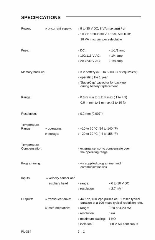
SPECIFICATIONS
Power: » bi-current supply: » 9 to 30 V DC, 8 VA max and / or
» 100/115/200/230 V ± 15%, 50/60 Hz,
16 VA max, jumper selectable
Fuse: » DC: » 1-1/2 amp
» 100/115 V AC: » 1/4 amp
» 200/230 V AC: » 1/8 amp
Memory back-up: » 3 V battery (NEDA 5003LC or equivalent)
» operating life 1 year
» ‘SuperCap’ capacitor for back-up during battery replacement
Range: » 0.3 m min to 1.2 m max ( 1 to 4 ft)
0.6 m min to 3 m max (2 to 10 ft)
Resolution: » 0.2 mm (0.007")
TemperatureRange: » operating: » –10 to 60 °C (14 to 140 °F)
» storage: » –20 to 70 °C (–4 to 158 °F)
TemperatureCompensation: » external sensor to compensate over
the operating range
Programming: » via supplied programmer and communication link
Inputs: » velocity sensor and
auxiliary head » range: » 0 to 10 V DC
» resolution: » 2.7 mV
Outputs: » transducer drive: » 44 Khz, 400 Vpp pulses of 0.1 msec typical duration at a 100 msec typical repetition rate.
» instrumentation: » range: 0-20 or 4-20 mA
» resolution: 5 uA
» maximum loading: 1 KΩ
» isolation: 300 V AC continuous
PL-384 2 – 1

» relays: » 3 alarm/control relays
» 1 form ’C’ SPDT contact per relay, rated at 8 A at 250 V AC non-inductive or 30 V DC
» relays are certified for use in equipment where the short circuit capacity of the circuits in which they are connected is limited byfuses having ratings not exceeding the rating of the relays.
» DC output: » +24 V DC
» 20 mA average to 200 mA at 1/10 duty cycle max
Communication: » RS-232 or ± 20 mA bipolar current loop,300,600, 1200, 2400, 4800, 9600 or 19200 baud
Data Logs: » variable rate on 1, 5, 15, 30 or 60 min or 24 hr
» 31 days minimum/2 years maximum
Display: » illuminated liquid crystal 5 x 7 dot matrix display with 2 lines of 40 characters each
Enclosure: » CSA type 4 / NEMA 4 ( style IP65 )
» 209 mm W x 285 mm H x 92 mm D(8.2" W x 11.2" H x 3.6" D)
» polycarbonate
Weight: » 2.3 Kg (5.1 lb)
PROGRAMMER
Enclosure: » general purpose
» 67 mm W x 100 mm H x 25 mm D(2.6" W x 4" H x 1" D)
» ABS plastic
Operating Temperature: » –20 to 50 °C
(–5 to 122 °F)
Battery: » 9 V (ANSI/NEDA 1604, PP3 or equivalent)
93/04/26PL-384 2 – 2
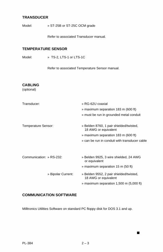
TRANSDUCER
Model: » ST-25B or ST-25C OCM grade
Refer to associated Transducer manual.
TEMPERATURE SENSOR
Model: » TS-2, LTS-1 or LTS-1C
Refer to associated Temperature Sensor manual.
CABLING(optional)
Transducer: » RG-62U coaxial
» maximum separation 183 m (600 ft)
» must be run in grounded metal conduit
Temperature Sensor: » Belden 8760, 1 pair shielded/twisted, 18 AWG or equivalent
» maximum separation 183 m (600 ft)
» can be run in conduit with transducer cable
Communication: » RS-232: » Belden 9925, 3 wire shielded, 24 AWG or equivalent
» maximum separation 15 m (50 ft)
» Bipolar Current: » Belden 9552, 2 pair shielded/twisted, 18 AWG or equivalent
» maximum separation 1,500 m (5,000 ft)
COMMUNICATION SOFTWARE
Milltronics Utilities Software on standard PC floppy disk for DOS 3.1 and up.
PL-384 2 – 3


INSTALLATION
INSTALLING THE OCM-3
The OCM-3 should be mounted in a clean, dry area that is: within the ambienttemperature range and suitable for the specified enclosure. The front cover should beaccessible for programming and viewing.
It is advisable to keep the OCM-3 away from high voltage or current runs, contactorsand SCR control drives.
Do not mount the OCM-3 in direct sunlight without the use of a sun shield.
209 mm(8.2")
lid screws(6 places)
106 mm(4.2")
91 mm(3.6")
16 mm(0.6")
285 mm(11.2")
267 mm(10.5")
programmer
lid, clearpolycarbonate
suitable location forconduit entrances
mounting holes(accessed underlid 4.3 mm (0.17")
dia.,4 places
CSA enclosure 4polycarbonate
customer mountingscrew
Milltronics recommends using a punch for making holes in enclosure.
172 mm(6.8")
OUTLINE AND MOUNTING
PL-384 3 – 1
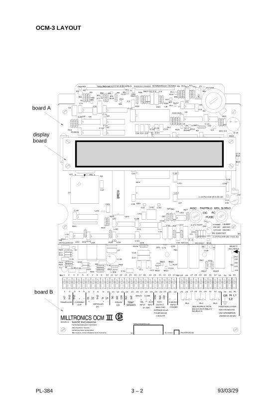
OCM-3 LAYOUT
board A
board B
93/03/29
EPRO
M
AK
CW
R7 D3
J1
TP16
R33
R36
R35
R32
Q1
TP6
TP7
TP10TP4
RC2RC1
TP9
TP3
R6TP1
R4TP2
R19
R18
R17
C24
C23
C12
U5
C19
TP8
C8
C10
C2
C25
C6
P1
C7
R9
U4C11
U3
R5
C1
C18U7
R3
TH1
R1
C9
U2
C53U36
R2
R16
U1
R14R15
C4 C5
U8
TP15
TP13
CR2
CR1
C47
U30
C48
U31
R20
U9C13
U35
C54
C38U27
C41
C42
U25
D5
R23
R24C49
C52R28
C45C44
U26
C36
U28
C58
C60
R27
Q2
C55
D4
R25R26
C62
R30
C57
C59
C56 D8
D7D6
C61
R29
R31
U32
C39
TP12
U23
RN1
B1
C15
C51
U22
U34
C43
U24
C37
C50
C14
C16 U6
C35
C46
TP5
TP14
R21
R22
U29
U10
U33
PM2
CLK
V
P12V
VEE
P5VR
N12V
ACOM
DCOM
P5VBLNK
PW
1PHASE
1-24751339-ZI-X-01-02
24751339-02PN
C24C23
1-24751339-ZG-X-01-02
60
22
9 PIN 1
MADE IN CANADAOCM III BOARD A
SN
1 1/2 AMP
FUSE
MILLTRONICS
TP9
TP21
TP20 TP22
TP23
TB2TB1
C51
C57
C56
OC2 OC3
C38
R48
R20 Q4
R47
R46
D17D18
D20
D19
C35
R21R22
C36L1
C39
R69
U7
R127 R128
Q23
D39
RL2
RL1
C37
R104C75
Q20U16
HD1
++
P12VI
ICOM
P5VI
N12VI
BLNK
__ ++RL3RL2RL1
_+
VAC
100
115
200
230
363534333231302928272625242322212019
363534333231302928272625242322212019181716151413121110987654321
181716151413121110987654321
RATINGS.BOOK FOR RELAYSEE INSTRUCTION
SN
SELECTVOLTAGE
displayboard
PL-384 3 – 2

INSTALLING THE TRANSDUCER
INSTALLING THE TEMPERATURE SENSOR
INSTALLING THE MEMORY BACK-UP BATTERY
Do not install the memory back-upbattery until the OCM-3 is to bepowered and ready for programming.
The unit is supplied with one batterypackage. Remove the battery fromthe package and insert it into thebattery socket.
Refer to Operation\Memory.
Basic Wiring – Transducer
93/03/29
Max cable run 183 m (600 ft) ofRG-62U or equivalent. Cable mustbe run in a grounded metal conduitwith no other cabling (exceptTemp. Sensor cable).
Ground shield at OCM-3 only.
Insulate shield at junctions toprevent inadvertent grounding.
Basic Wiring – Temperature Sensor
Maximum cable run 183 m (600 ft) ofBeldon 8760, 1 pair shielded/twisted, 18 AWG or equivalent.
Temperature sensor cable can be runwith the transducer cable in a groundedmetal conduit.
Ground shield at OCM-3 only.
In order to compensate for uniformtemperature change in the airbetween the transducer and the flowsurface, the temperature sensormust be connected to the OCM-3.
PL-384 3 – 3
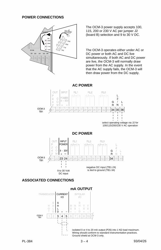
POWER CONNECTIONS
The OCM-3 power supply accepts 100,115, 200 or 230 V AC per jumper J2(board B) selection and 9 to 30 V DC.
The OCM-3 operates either under AC orDC power or both AC and DC livesimultaneously. If both AC and DC powerare live, the OCM-3 will normally drawpower from the AC supply. In the eventthat the AC supply fails, the OCM-3 willthen draw power from the DC supply.
ASSOCIATED CONNECTIONS
AC POWER
93/04/26
DC POWER
select operating voltage via J2 for100/115/200/230 V AC operation
9 to 30 VoltDC input
negative DC input (TB1-24)is tied to ground (TB1-34)
mA OUTPUT
isolated 0 or 4 to 20 mA output (P26) into 1 KΩ load maximum. Wiring should conform to standard instrumentation practices. Ground shield at OCM-3 only.
PL-384 3 – 4
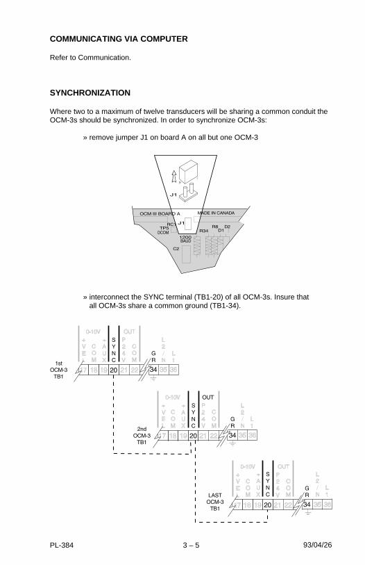
COMMUNICATING VIA COMPUTER
Refer to Communication.
SYNCHRONIZATION
Where two to a maximum of twelve transducers will be sharing a common conduit theOCM-3s should be synchronized. In order to synchronize OCM-3s:
» remove jumper J1 on board A on all but one OCM-3
» interconnect the SYNC terminal (TB1-20) of all OCM-3s. Insure that all OCM-3s share a common ground (TB1-34).
93/04/26PL-384 3 – 5

INSTALLING THE PROGRAMMER
To program the OCM-3 via the Programmer, it must be placed into the front coverrecess of the OCM-3. The back of the Programmer has a magnetic plate which willhold the programmer in place. It can be removed when programming is completed.
CHECKS
» insure that all wiring is securely fastened and connected to the proper terminals.
» insure that the proper fuses have been installed.
» insure that the memory battery has been correctly installed.
» insure that the proper voltage supply is being provided and that for AC supply, the voltage stab connector, J2, is properly set.
PL-384 3 – 6
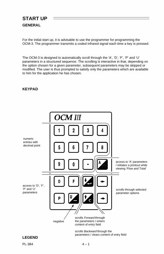
START UPGENERAL
For the initial start up, it is advisable to use the programmer for programming theOCM-3. The programmer transmits a coded infrared signal each time a key is pressed.
The OCM-3 is designed to automatically scroll through the ‘A’, ‘D’, ‘F’, ‘P’ and ‘U’parameters in a structured sequence. The scrolling is interactive in that, depending onthe option chosen for a given parameter, subsequent parameters may be skipped ormodified. The user is thus prompted to satisfy only the parameters which are availableto him for the application he has chosen.
KEYPAD
LEGEND
access to ‘D’, ‘F’,‘P’ and ‘U’parameters
scrolls Forward throughthe parameters / enters content of entry field
scrolls Backward through the parameters / clears content of entry field
negative
scrolls through selectedparameter options
access to ‘A’ parameters / initiates a printout whileviewing ‘Flow and Total’
numericentries withdecimal point
PL-384 4 – 1
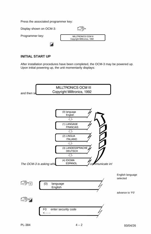
Press the associated programmer key:
Display shown on OCM-3:
Programmer key:
INITIAL START UP
After installation procedures have been completed, the OCM-3 may be powered up.Upon initial powering up, the unit momentarily displays:
and then scrolls through the available languages:
The OCM-3 is asking which language you prefer to communicate in!
English language selected
advance to ‘F0’
93/04/26
F0 enter security code< - - -
(0) languageEnglish
0
PL-384 4 – 2
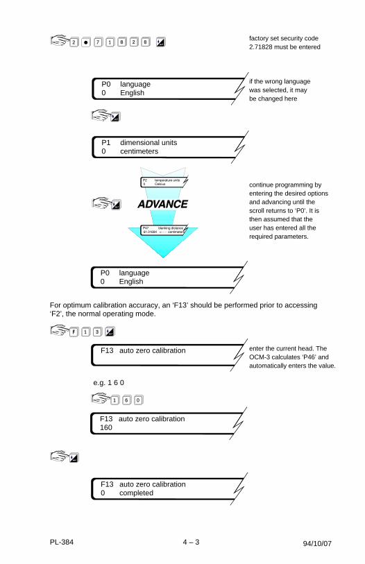
factory set security code2.71828 must be entered
if the wrong language was selected, it may be changed here
continue programming by entering the desired options and advancing until the scroll returns to ‘P0’. It is then assumed that the user has entered all the required parameters.
For optimum calibration accuracy, an ‘F13’ should be performed prior to accessing‘F2’, the normal operating mode.
enter the current head. TheOCM-3 calculates ‘P46’ andautomatically enters the value.
e.g. 1 6 0
94/10/07
P1 dimensional units0 centimeters
F13 auto zero calibration
P0 language0 English
F13 auto zero calibration0 completed
P0 language0 English
3
1 8 2 872
1
F13 auto zero calibration160
01 6
PL-384 4 – 3
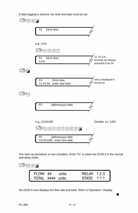
If data logging is desired, the time and date must be set.
e.g. 1141
11: 41 a.m.,seconds are alwaysassumed to be 00
time is displayed in hh:mm:ss
e.g. 12101492 October 12, 1492
The start up procedure is now complete. Enter ‘F2’ to place the OCM-3 in the normaloperating mode.
the OCM-3 now displays the flow rate and total. Refer to Operation \ Display
F4 24-hr time1141
41 1
F4 24-hr time11:41:00 enter new time
F5 (ddmmyyyy) date
F5 (ddmmyyyy) date12/10/1492 enter new date
0 1 4
2
9 211 2
F4 24-hr time
4
1
PL-384 4 – 4

OPERATION
Upon power up, the transducer is fired periodically as set by P36. A long intervalbetween measurements may be desirable in order to conserve power when operatingthe OCM-3 from a DC source of limited capacity.
The echo is processed to determine the head (D0). The flow rate (D1) is calculated bythe OCM-3 as a mathematical function (P3 and P4) of head or a function of head andvelocity (P42). The flow rate is then integrated to yield the totalized flow (D2). The‘Flow’ and ‘Total’ fields which are displayed during the normal running mode (F2) arealso continuously updated.
Viewing or changing the content of a parameter (except F1, emulation) is donewithout disturbing the acquisition, processing or logging of flow data (see \ Security).
MEMORY
During a power interruption, the memory back up will hold the programming, the logand the totalizer values, and run the clock. The memory battery (B1) provides up toone year of memory retention (see Appendices \ Maintenance).
SECURITY
The content of all ‘A’, ‘D’, ‘F’, ‘P’ and ‘U’ parameters can be viewed without having tosatisfy the security parameter, F0. However if it is desired to change the content ofany of these parameters, the security parameter must be satisfied (except forresetting the running min/max displays, parameters D3/D4 and D6/D7).
Once security has been satisfied, access continues for 5 minutes after the last key ispressed or until F2 is re-entered.
The security code may be changed from its factory set value, 2.71828, by entering anew value into F10. It is imperative that the new value be recorded, as the code cannot be viewed. If the code is lost, consult Milltronics.
UNITS
Programming of the OCM-3 involves setting the units of measure:
» P1 linear and velocity
» P2 temperature
» P5 flow rate and volume
If the units are changed during the course of operation, the change will be effectedthrough all associated parameters and displays and will rescale flow and total datastored in the logs.
PL-384 5 – 1
FLOW CALCULATION
Absolute vs. ratiometric
The OCM-3 can be programmed to use either of two methods (P4) for calculating flowfrom the head measurement: absolute or ratiometric. The result is the sameregardless of the method used. The principal difference is the information that mustbe entered in order for the OCM-3 to carry out the calculation. The user’s choice ofmethod may ultimately be based upon the information which is at hand. Refer to Uparameters for the primary element selected for a listing of the information required.
For the ratiometric method, it is usually sufficient that the user know the flow rate(Qcal) which occurs at maximum head (hcal).
On the other hand, absolute calculations require that the user enter information suchas: the physical dimensions of the primary element and the constant relating to unitsof measure for both linear dimensions and flow rates.
e.g. the general formula for flow through a single exponent primary element is:
Q = KHx
the specific formula for flow through a 45° V-notch weir is:
cfs = 1.03H2.5
thus: Q = flow in cubic feet per secondK = constant of 1.03H = head in feet
The absolute method is not applicable to the following:
Palmer Bowlus flumeH flume
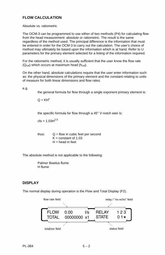
DISPLAY
The normal display during operation is the Flow and Total Display (F2).
status field
flow rate field
totalizer field
relay / "no echo" field
PL-384 5 – 2

Flow Rate Field
Totalizer Field
Relay / No Echo Field
Status Field
The OCM-3 provides illumination for the LCD for easier viewing of the display.Illumination can be set (P14) to be normally on or off, or automatic. When automatic isselected, the lighting will automatically go on when keypad activity is sensed and thenextinguish after 15 seconds of inactivity.
DAMPING
The OCM-3 provides two separate damping functions: reading and mA output. Zeroor no damping allows fastest response while high or 100% provides the slowestresponse. The damping is usually set to provide a reliable response without sacrificingstability.
The reading damping, P13, dampens only the flow rate reading of the ‘Flow and Total’display F2. The damping selections are: off, low, medium and high. Relay functionsassociated with flow rate respond to the dampened reading values.
mA output damping, P27, dampens the change in the mA output. The parameter entryis in seconds for spanning the 0 to 100% of the mA range selected (P26). Displaysand relay functions associated with the mA output respond to its dampened value.
flow rate
total
units, P5
multiplier, P32
relay identification
under loss of echocondition, "NOECHO" willalternately flash
relay status :0 = relay de-energized1 = relay energized = alarm state (indicated when flashing)*
PL-384 5 – 3

RELAYS
Three on board multipurpose relays are provided by the OCM-3. P15, 18 and 21 setthe respective functions for relays 1, 2 and 3. Depending on the function selected,these parameters determine the need and configuration of the subsequent relaycontrol parameters, P16, 17 (relay 1); P19, 20 (relay 2) and P22, 23 (relay 3).
If the relay is to function as a driver for a remote totalizer or as a flow sampler contact,the setpoint will be factored by the totalizer multiplier (P32).
The status of each relay is shown in the display. Refer to \ Flow and Total Display.
mA OUTPUT
The OCM-3 provides a mA output (TB1-4/5) which can be assigned (P24) torepresent the measurement of flow, head, velocity or temperature. The associatedscaling, P25, is factory set to a value of ‘0’. This provides normal scaling with respectto the assigned measurement.
Normal scaling for representation of flow, head or velocity is:
» 0 or 4 mA = 0
» 20 mA = maximum measurement value for: » P6*: flow rate at maximum head
» P7: maximum head
» P10: velocity at maximum head
Normal scaling for representation of temperature is:
» 0 or 4 mA = – 40 °C
» 20 mA = 60 °C
If custom scaling is required, the 20 mA corresponding value (other than 0) can beentered into P25. The range (0 to 20 or 4 to 20 mA) and damping (see Damping) areset via P26 and P27 respectively.
The mA function can be overridden for test purposes by setting the desired mA valueinto F3. When the value is entered, the mA output will go to that value. When F3 isexited, the mA output will revert to normal operation. Also, see \ Emulation Mode.
*In the case of absolute calculations (P4=0), P6 is calculated by the OCM-3.
PL-384 5 – 4
FAIL-SAFE
In the event of an echo loss, the fail-safe timer will begin counting. If the echo lossduration surpasses that of the time set (P29), a ‘No Echo’ alert will be displayed in theStatus field (see \ Display). The mA output will respond (P30) by either holding the lastvalue or immediately going to a predetermined value (P31). The head and derivedflow will hold their last value and totalization and logging will continue, based on thatvalue. Upon resumption of a valid echo, the mA output will return to a valuecorresponding to the present value of the measurement assigned, at the mA dampingrate (P27).
FLOW RATE AND TOTALIZING
Flow rate
Calculation of the flow rate is ongoing. It is normally viewed under the Flow and Totaldisplay (F2) with the decimal point set per P33. It can also be viewed under D1 as theraw flow calculation. Data on the running minimum and maximum flows that haveoccurred since the last reset can be viewed in two ways:
» F7 gives the running min/max flows and their time and date of occurrence since the last reset. F7 is reset by F8 but only after satisfying the security parameter F0.
» D3/D4 give the respective running min/max flow data, only, that have occurred since they were last reset. D3/D4 are reset simultaneously by entering 0 into either D3 or D4. D3 and D4 will then adopt the current flow rate and track the running min/max values from that point on. The security parameter (F0) does not need to be satisfied in order to reset D3/D4.
Flow data specific to a particular time and date can be viewed under the data log F14(see \ Logging).
Totalizing
Totalizing of the calculated flow is ongoing. It is normally viewed under the Flow andTotal display (F2).
An auxiliary totalizer (D2) is provided for operator usage and is intended for short termtotalizing to a maximum count of 999999. It can be reset or preset independently ofthe F2 totalizer after satisfying the security parameter (F0).
In order to adjust the rate of filling of the totalizer, the totalizer multiplier (P32) can beset to an appropriate value. The totalizer can be reset via F11. Totalizing that isspecific to the time and date can be viewed under the data log F14.
The OCM-3 can be programmed to operate a remote totalizer by assigning any of therelays (P15, 18 or 21) to act as a totalizer contact. Under this function, the maximumrate of contact closure is 2/sec with a closure duration of 200 msec
Under low flow conditions, a cut-off head (P45) can be entered to avoid totalizingflows occurring at or below the flow corresponding to the cut-off head.
PL-384 5 – 5

LOGGING
The OCM-3 provides an extensive logging feature which can be viewed on the localdisplay or retrieved via the serial communication link. The logging rate (P39) can befixed or variable. The latter being useful in conserving logging space. The condition forvariable logging is determined when selecting the logging rate.
Variable logging rate conditions are catagorized as : rate of change of flow, percent ofmaximum flow or percent of maximum head. Logging occurs at the normal (slower)rate while the condition is less than the setpoint (P40). If the condition exceeds the lograpid setpoint, the rapid rate of logging takes effect until the condition falls below thelog normal setpoint (P41).
The associated setpoint units are : % change of maximum flowrate per minute, % ofmaximum flowrate and % of maximum head, respectively. The setpoints represent theabsolute value of the rate of change; that is, for either increasing or decreasingflowrate. The OCM-3 does not recognize negative entries into P-40 and P-41.
Log Capacity vs Rates
rate capacity
1 min 31 days
5 3 months
15 9 months
30 1 year
60 1.5 years
24 hr 2 years
e.g. 15 / 5 9 months max / 3 months min
Once the log is filled, the old data will be successively written over with the new data being logged.
The log can be examined via F14. Viewing of the log is done by task and by method.The viewing tasks are: daily flow totals, flow rates and min-max flow data for flow ortemperature. The viewing methods are: by first entry, by last entry and by specifieddate. The scrolling keys are used to maneuver through the tasks, methods and time of day.
94/10/07PL-384 5 – 6
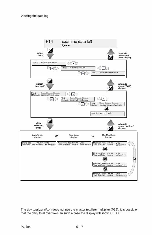
Viewing the data log
The day totalizer (F14) does not use the master totalizer multiplier (P32). It is possiblethat the daily total overflows. In such a case the display will show +++.++.
PL-384 5 – 7
BLANKING
Blanking is used to ignore the zone in front of the transducer where ringing or otherfalse echo is at a level that interferes with the processing of the true echo. Theminimum blanking is factory set, but can be overridden by entering the desireddistance into P47.
Ringing is the inherent nature of the transducer mass to continue vibrating after thetransducer has been fired. Ringing decays to acceptable levels in the order ofmilliseconds. Excessive cold or over tightening of the transducer mounting mayincrease the ring time such that it appears as an echo during the receive cycle. This isusually indicated by an incorrect high head reading. Excessive ring time may beovercome by increasing the blanking.
TEMPERATURE
The temperature as currently registered by the temperature sensor is viewed underD5. Data on the running minimum and maximum temperatures that have occurredsince the last reset can be viewed in several ways:
F7 gives the running min/max temperatures and their time and date of occurrencesince the last reset. F7 is reset by F8 but only after satisfying the security parameter F0.
D6/D7 give the respective running min/max temperature data, only, that haveoccurred since they were last reset. D6 is reset by entering a value lower than D5,and D7 is reset by entering a value larger than D5. D6 and D7 will then adopt thecurrent temperature value and track the min/max values from that point on. Thesecurity parameter F0 does not need to be satisfied in order to reset D6 or D7.
Temperature data specific to the time and date can be viewed under the data log F14(see \ Logging).
D14 indicates the resistance of the temperature sensor corresponding to thetemperature shown in D5.
TIME AND DATE
If the data logging features of the OCM-3 are to be used, the time (F4) and date (F5)must be set. The day starts at 00:00:00 and ends at 23:59:59.
Adjusting the Time
If the clock time is advanced beyond the next anticipated logging time, the entry foreach missed logging time is filled with a code which indicates that the system was notable to make entries at those times.
The daily total will be reduced proportional to the amount of time the day was shortened.
If the clock time is set back beyond the preceding logging time, the previously loggeddate will be written over with new data as the logging proceeds.
PL-384 5 – 8
The daily total will be increased proportional to the amount of time the day waslengthened.
Adjusting the Date
If the calendar is reset, the OCM-3 will adjust the log dates accordingly, taking intoaccount leap years and days per month.
EMULATION MODE
The flow calculation (P3/P4) can be checked for accuracy by using the emulationparameter F1. The head is entered and the corresponding flow is displayed. Thisfunction is useful when troubleshooting discrepancies between the OCM-3 calculationand the expected flow.
Relays assigned to functions associated with the emulation parameter respond to theemulated flows.
The mA output does not track the emulated flows when P28 (mA output emulation) =0. However, if it is required to do so, then the emulator parameter should be set to 1.
RESET
The following resets can only be executed after satisfying the security access, F0.
Cold Start
If it is desired to reset all parameters, logs and totalizers to their factory setting, this isdone by forcing a cold start, F12.
Master Totalizer
If it is desired to reset the master totalizer (F2), this is done by parameter F11.
Data Log
If it is desired to reset the data log (F14), this is done by parameter F15.
Min/Max Log
If it is desired to reset the min/max log (F7), this is done by parameter F8.
PL-384 5 – 9

FLOW VELOCITY INPUT
In some applications, the flow calculation for chosen primary element requires avelocity input. In this type of application, the transducer measurement is used tocalculate the cross sectional area of the flow. By multiplying the area with the distanceper time units of velocity, the volume per time units of flow are calculated. Thecalculated velocity can be viewed via D8.
The 0% and 100% limits of the velocity input must be scaled using parameters P8 andP9. » select P8
» enter the voltage corresponding to zero velocity» select P9» enter the velocity corresponding to 5 V
e.g. If the velocity sensor output is 1 V per m/sec and the output is scaled for 7 V at 100% velocity (7 m/sec), then enter 5 m/sec. If theoutput is scaled for 4 V at 100% velocity (4 m/sec), enter 5 m/sec.
P8 and P9 can only be accessed if P3 has been set for an option that requires the useof a velocity input. The input voltage level can be viewed via D12.
AUXILIARY HEAD INPUT
In some applications, the transducer input (TB1-1/2) is not used to provide a signal forhead measurement. A typical example of this is an application which is beyond the 3m (10 ft) range of the OCM-3. In such a case, the head could be derived from anotherMilltronics level monitor or other compatible device.
The method of head determination is set by P42. The OCM-3 simply substitutes thesignal from the auxiliary device for the ultrasonic measurement provided by thetransducer. The programming and consequent flow calculation are performed as normal.
Voltage Input
typical 1 - 5 V signal fromvelocity sensor.
typical 4 - 20 mA signal from velocity sensor.Add terminating resistor. e.g. 250 Ω for 1 - 5 V over 4 - 20 mA.
Current Input
Velocity Input(additional to Basic Wiring)
Signal must be positive with respect to ground.
PL-384 5 – 10
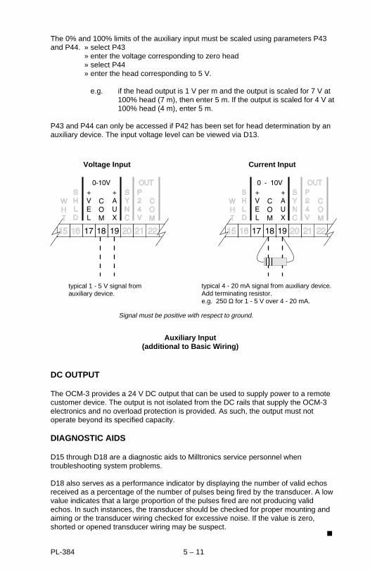
The 0% and 100% limits of the auxiliary input must be scaled using parameters P43and P44. » select P43
» enter the voltage corresponding to zero head» select P44» enter the head corresponding to 5 V.
e.g. if the head output is 1 V per m and the output is scaled for 7 V at 100% head (7 m), then enter 5 m. If the output is scaled for 4 V at 100% head (4 m), enter 5 m.
P43 and P44 can only be accessed if P42 has been set for head determination by anauxiliary device. The input voltage level can be viewed via D13.
DC OUTPUT
The OCM-3 provides a 24 V DC output that can be used to supply power to a remotecustomer device. The output is not isolated from the DC rails that supply the OCM-3electronics and no overload protection is provided. As such, the output must notoperate beyond its specified capacity.
DIAGNOSTIC AIDS
D15 through D18 are a diagnostic aids to Milltronics service personnel whentroubleshooting system problems.
D18 also serves as a performance indicator by displaying the number of valid echosreceived as a percentage of the number of pulses being fired by the transducer. A lowvalue indicates that a large proportion of the pulses fired are not producing validechos. In such instances, the transducer should be checked for proper mounting andaiming or the transducer wiring checked for excessive noise. If the value is zero,shorted or opened transducer wiring may be suspect.
Voltage Input
typical 1 - 5 V signal fromauxiliary device.
typical 4 - 20 mA signal from auxiliary device.Add terminating resistor. e.g. 250 Ω for 1 - 5 V over 4 - 20 mA.
Auxiliary Input(additional to Basic Wiring)
Signal must be positive with respect to ground.
Current Input
PL-384 5 – 11

‘D’ PARAMETER LISTING
Refer to ‘Operation’ for details.
D0 head
D1 flow rate
D2 short total *
D3 maximum flow rate
D4 minimum flow rate
D5 temperature
D6 maximum temperature
D7 minimum temperature
D8 velocity
D9 nominal target range
D10 analog milliamps
D11 internal DC volts
D12 velocity volts
D13 auxiliary input volts
D14 temperature sensor ohms
D15 self-test checksum
D16 restarts
D17 exceptions
D18 valid echos per 100
*security access required
applicable to flow calculations requiring velocity sensor
94/10/07PL-384 6 – 1

This page intentionally left blank.
PL-384 6 – 2

‘F’ PARAMETER LISTING
Refer to ‘Operation’ for details.
F0 enter security code
F1 emulation mode*
F2 run mode
F3 keypad to mA output *
F4 show time
set time*
F5 show date
set date*
F6 software identification number
F7 view min/max data
F8 reset min/max data*
F9 self check*
F10 change security code*
F11 reset master totalizer*
F12 force a cold start*
F13 auto zero calibration*
F14 examine data log:
task: view daily totals
view flow rates
view min/max data
method:
first day
last day
specified day
F15 clear data log*
*security access required
PL-384 6 – 3

This page intentionally left blank.
PL-384 6 – 4
‘P’ PARAMETER LISTING
Refer to ‘Operation’ for details.
P0 language
0 = english
1 = french
2 = italian
3 = german
4 = spanish
P1 dimensional units
linear velocity
0 = centimetres centimetres per second
1 = inches inches per second
2 = feet feet per second
3 = metres metres per second
P2 temperature units
0 = Celcius
1 = Fahrenheit
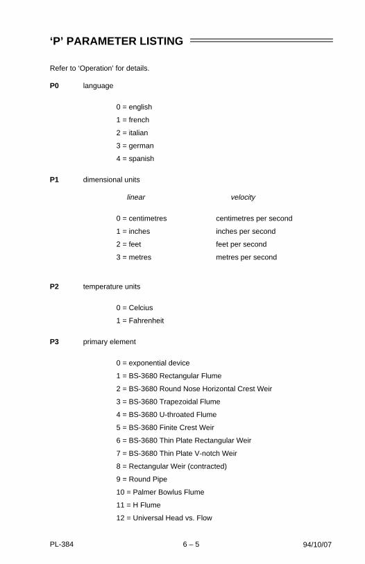
P3 primary element
0 = exponential device
1 = BS-3680 Rectangular Flume
2 = BS-3680 Round Nose Horizontal Crest Weir
3 = BS-3680 Trapezoidal Flume
4 = BS-3680 U-throated Flume
5 = BS-3680 Finite Crest Weir
6 = BS-3680 Thin Plate Rectangular Weir
7 = BS-3680 Thin Plate V-notch Weir
8 = Rectangular Weir (contracted)
9 = Round Pipe
10 = Palmer Bowlus Flume
11 = H Flume
12 = Universal Head vs. Flow
94/10/07PL-384 6 – 5
13 = Rectangular Area x Velocity
14 = Trapezoidal Area x Velocity
15 = Modified Trapezoidal Area x Velocity
16 = U-channel Area x Velocity
17 = Circular Area x Velocity
18 = Gull-wing Area x Velocity
19 = Egg-shaped Area x Velocity
20 = Universal Area x Velocity
P4 method of calculation
0 = absolute
1 = ratiometric
P5 flow rate units
flowrate volume
0 = litres per second litres
1 = cubic feet per second cubic feet
2 = imperial gallons per minute imperial gallons
3 = U.S. gallons per minute U.S. gallons
4 = imperial million gallons per day imperial million gallons
5 = U.S. million gallons per day U.S. million gallons
6 = cubic metres per hour cubic metres
7 = cubic metres per day cubic metres
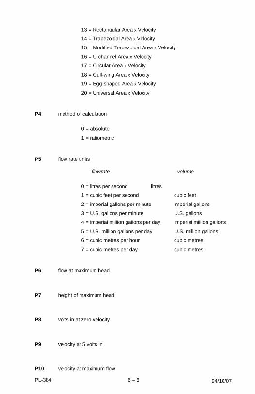
P6 flow at maximum head
P7 height of maximum head
P8 volts in at zero velocity
P9 velocity at 5 volts in
P10 velocity at maximum flow
94/10/07PL-384 6 – 6

P13 display damping
0 = off
1 = low
2 = med
3 = high
P14 display lighting
0 = on
1 = auto off
2 = off
P15 / P18 / P21 relay 1 / 2 / 3 assignment
0 = not in service
1 = de-energize on loss of echo
2 = energize on loss of echo
3 = de-energize on high flow rate
4 = energize on high flow rate
5 = de-energize on low flow rate
6 = energize on low flow rate
7 = de-energize on high head
8 = energize on high head
9 = de-energize on low head
10 = energize on low head
11 = de-energize on high velocity
12 = energize on high velocity
13 = de-energize on low velocity
14 = energize on low velocity
15 = de-energize on high analog
16 = energize on high analog
17 = de-energize on low analog
18 = energize on low analog
19 = de-energize on low D11 volts
20 = energize on low D11 volts
21 = de-energize on high D11 volts
22 = energize on high D11 volts
23 = de-energize on low Aux. volts
94/10/07PL-384 6 – 7
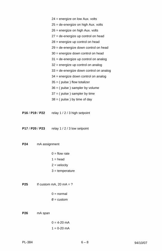
24 = energize on low Aux. volts
25 = de-energize on high Aux. volts
26 = energize on high Aux. volts
27 = de-energize up control on head
28 = energize up control on head
29 = de-energize down control on head
30 = energize down control on head
31 = de-energize up control on analog
32 = energize up control on analog
33 = de-energize down control on analog
34 = energize down control on analog
35 = ( pulse ) flow totalizer
36 = ( pulse ) sampler by volume
37 = ( pulse ) sampler by time
38 = ( pulse ) by time of day
P16 / P19 / P22 relay 1 / 2 / 3 high setpoint
P17 / P20 / P23 relay 1 / 2 / 3 low setpoint
P24 mA assignment
0 = flow rate
1 = head
2 = velocity
3 = temperature
P25 If custom mA, 20 mA = ?
0 = normal
0 = custom
P26 mA span
0 = 4-20 mA
1 = 0-20 mA
94/10/07PL-384 6 – 8
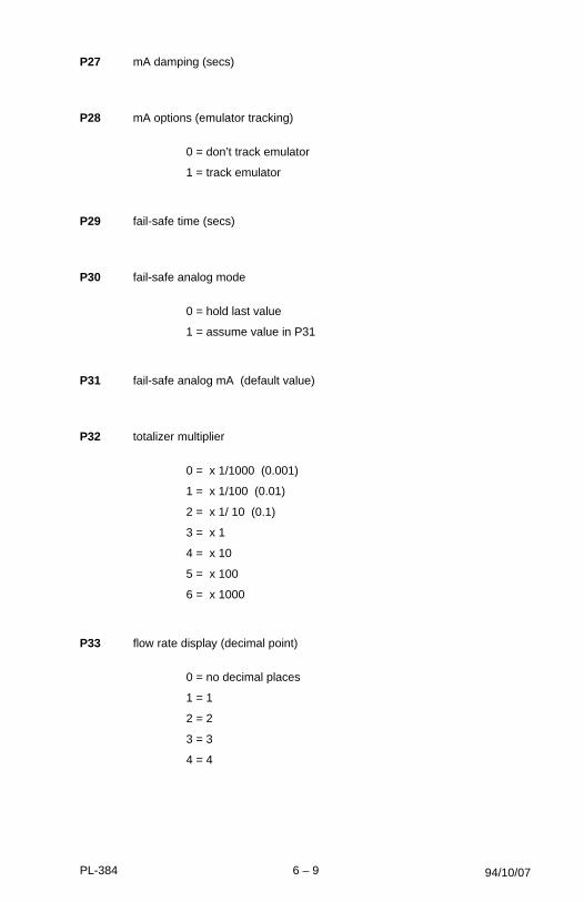
P27 mA damping (secs)
P28 mA options (emulator tracking)
0 = don’t track emulator
1 = track emulator
P29 fail-safe time (secs)
P30 fail-safe analog mode
0 = hold last value
1 = assume value in P31
P31 fail-safe analog mA (default value)
P32 totalizer multiplier
0 = x 1/1000 (0.001)
1 = x 1/100 (0.01)
2 = x 1/ 10 (0.1)
3 = x 1
4 = x 10
5 = x 100
6 = x 1000
P33 flow rate display (decimal point)
0 = no decimal places
1 = 1
2 = 2
3 = 3
4 = 4
94/10/07PL-384 6 – 9

P34 printer mode
0 = never print
1 = interval to be in minutes
2 = interval to be in hours
3 = print once each day
P35 printer timing
P36 measurement interval
0 = 1 sec
1 = 15 sec
2 = 30 sec
3 = 1 min
4 = 5 min
P37 serial data rate
0 = 300 baud
1 = 600
2 = 1200
3 = 2400
4 = 4800
5 = 9600
6 = 19200
P38 site number
94/10/07PL-384 6 – 10
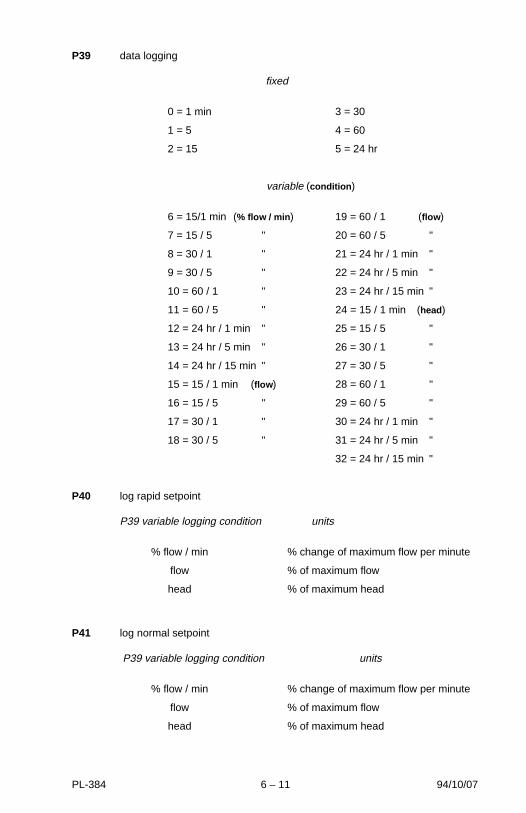
P39 data logging
fixed
0 = 1 min 3 = 30
1 = 5 4 = 60
2 = 15 5 = 24 hr
variable (condition )
6 = 15/1 min (% flow / min ) 19 = 60 / 1 (flow )
7 = 15 / 5 " 20 = 60 / 5 "
8 = 30 / 1 " 21 = 24 hr / 1 min "
9 = 30 / 5 " 22 = 24 hr / 5 min "
10 = 60 / 1 " 23 = 24 hr / 15 min "
11 = 60 / 5 " 24 = 15 / 1 min (head)
12 = 24 hr / 1 min " 25 = 15 / 5 "
13 = 24 hr / 5 min " 26 = 30 / 1 "
14 = 24 hr / 15 min " 27 = 30 / 5 "
15 = 15 / 1 min (flow ) 28 = 60 / 1 "
16 = 15 / 5 " 29 = 60 / 5 "
17 = 30 / 1 " 30 = 24 hr / 1 min "
18 = 30 / 5 " 31 = 24 hr / 5 min "
32 = 24 hr / 15 min "
P40 log rapid setpoint
P39 variable logging condition units
% flow / min % change of maximum flow per minute
flow % of maximum flow
head % of maximum head
P41 log normal setpoint
P39 variable logging condition units
% flow / min % change of maximum flow per minute
flow % of maximum flow
head % of maximum head
94/10/07PL-384 6 – 11

P42 head determination
0 = by OCM-3
1 = by auxiliary device
P43 volts in for zero head
P44 head at 5 volts in
P45 low flow cut-off head
P46 range at zero head
P47 blanking distance
94/10/07PL-384 6 – 12

‘U’ PARAMETERS FOR P3 PRIMARY ELEMENT
The number of ‘U’ parameters required varies according to the primary elementchosen (P3) and the method of calculation (P4). The OCM-3 prompts the user bydisplaying the next required parameter, insuring the programming is complete.
The following is a list of the specific primary elements to which the OCM-3 can beapplied.
Refer to the page covering your particular application; the rest may be disregarded.
P3 primary element
0 exponential device (e.g. proportional, V-notch, Parshall etc)
1 BS-3680 Rectangular Flume (ISO 4359)
2 BS-3680 Round Nose Horizontal Crest Weir (ISO 4374)
3 BS-3680 Trapezoidal Flume (ISO 4359)
4 BS-3680 U-throated Flume (ISO 4359)
5 BS-3680 Finite Crest Weir (ISO 3846)
6 BS-3680 Thin Plate Rectangular Weir (ISO 1438/1)
7 BS-3680 Thin Plate V Notch Weir (ISO 1438/1)
8 Rectangular Weir (contracted)
9 Round Pipe
10 Palmer-Bowlus Flume
11 H Flume
12 Universal Head vs. Flow
13 Rectangular Area x Velocity
14 Trapezoidal Area x Velocity
15 Modified Trapezoidal Area x Velocity
16 U-channel Area x Velocity
PL-384 6 – 13

17 Circular Area x Velocity
18 Gull Wing Area x Velocity
19 Egg-shaped Area x Velocity
20 Universal Area x Velocity
The primary element must be installed in accordance with the manufacturersrecommendations and in accordance with all governing regulations.
PL-384 6 – 14

SIMPLE EXPONENTIAL DEVICES, P3 = 0
‘U’ parameters required *
U0 = exponent
U1 = k factor (P4 = 0 only)
Typical Exponential Devices:
» Sutro (proportional) weir
» head measurement only
» Rectangular (suppressed) or Trapezoidal (Cipolletti) weir
» Kahfagi venturi
» Parshall flume
» Leopold Lagco
» Triangular (V-notch) weir
*obtain from manufacturer’s specifications.
Reference
ABSOLUTE CALCULATION, P4 = 0¤
For flows that can be calculated by the equation:
q = k hx
where q = flowrate x = exponent (U0)k = constant factor (U1) h = head
RATIOMETRIC CALCULATION, P4 = 1¤
For flows that can be calculated by the equation:
q = qcal (h/hcal)x
where q = flowrate qcal = flowrate at maximum headh = head hcal = maximum headx = exponent (U0)
Refer to manufacturers specifications for the exponent value.
¤ Refer to Operation \ Flow Calculation.
PL-384 6 – 15

SIMPLE EXPONENTIAL DEVICES, P3 = 0
TYPICAL SHARP-CRESTED WEIRS
Typical Weir Profiles
For rated flows under free flow conditions, the head is measured upstream of the weirplate at a minimum distance of 3 times the maximum head (i.e. where the liquidsurface is not effected by drawdown).
Trapezoidal (Cipolletti)U 0 = 1.5
Sutro (Proportional)U 0 = 1
(symmetrical or asymmetrical)
V - notch or TriangularU 0 = 2.5
transducer *
Rectangular - suppressedU 0 = 1.5
minimum3 x h max
* The transducer must be above the maximum head by at least the blanking value, P47.
PL-384 6 – 16
SIMPLE EXPONENTIAL DEVICES, P3 = 0
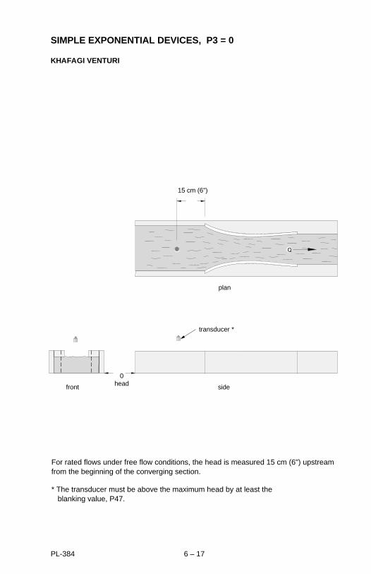
KHAFAGI VENTURI
transducer *
plan
sidefront
0head
15 cm (6")
For rated flows under free flow conditions, the head is measured 15 cm (6") upstreamfrom the beginning of the converging section.
* The transducer must be above the maximum head by at least the blanking value, P47.
PL-384 6 – 17
SIMPLE EXPONENTIAL DEVICES, P3 = 0
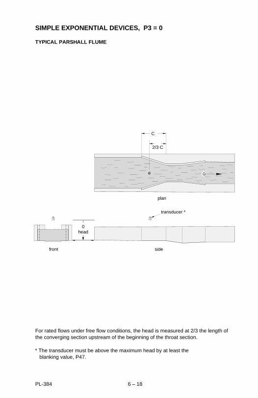
TYPICAL PARSHALL FLUME
For rated flows under free flow conditions, the head is measured at 2/3 the length ofthe converging section upstream of the beginning of the throat section.
transducer *
plan
sidefront
C
2/3 C
0head
* The transducer must be above the maximum head by at least the blanking value, P47.
PL-384 6 – 18
SIMPLE EXPONENTIAL DEVICES, P3 = 0
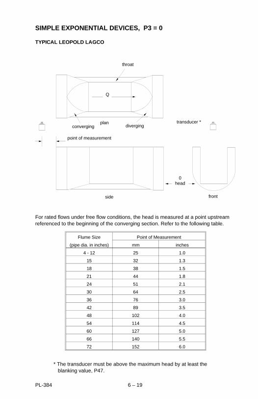
TYPICAL LEOPOLD LAGCO
For rated flows under free flow conditions, the head is measured at a point upstreamreferenced to the beginning of the converging section. Refer to the following table.
side
point of measurement
front
0head
transducer *diverging
plan
Q
throat
converging
Flume Size Point of Measurement
(pipe dia. in inches) mm inches
4 - 12 25 1.0
15 32 1.3
18 38 1.5
21 44 1.8
24 51 2.1
30 64 2.5
36 76 3.0
42 89 3.5
48 102 4.0
54 114 4.5
60 127 5.0
66 140 5.5
72 152 6.0
* The transducer must be above the maximum head by at least the blanking value, P47.
PL-384 6 – 19

BS-3680 Rectangular Flume, P3 = 1
‘U’ parameters required * ‘U’ parameters calculated **
U0 = approach width B U4 = Cv
U1 = throat width b U5 = Cd
U2 = hump height p U6 = A
U3 = throat length L
*obtain from manufacturer’s specifications.
**calculated by OCM-3. May be viewed by accessing ‘U’ parameter.
Reference
ABSOLUTE CALCULATION, P4 = 0¤
For flows that can be calculated by the equation:
q = (2/3)1.5 x g0.5 x Cv x Cs x Cd x B x h1.5
where : q = flow rate Cv = velocity coefficient
b = throat width Cs = shape coefficient
g = gravitational acceleration Cd = discharge coefficient
h = head
RATIOMETRIC CALCULATION, P4 = 1¤
For flows that can be calculated by the equation:
q = qcal x Cd/Cdcal x Cv/Cvcal x (h/hcal)1.5
where : q = flow rate
qcal = flow rate at maximum head
h = head
hcal = maximum head
Cv = velocity coefficient
Cvcal = velocity coefficient for maximum head
Cd = discharge coefficient for head
Cdcal = discharge coefficient for maximum head
¤ Refer to Operation \ Flow Calculation.
PL-384 6 – 20
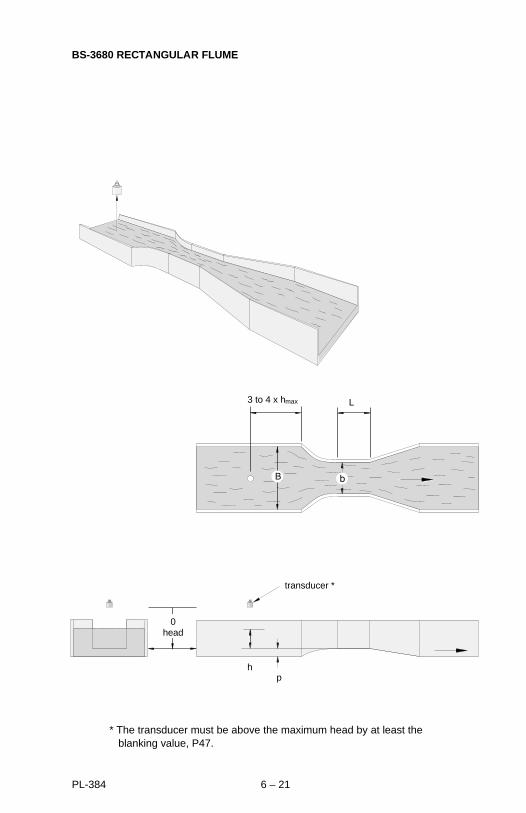
BS-3680 RECTANGULAR FLUME
3 to 4 x hmax
ph
L
0head
transducer *
* The transducer must be above the maximum head by at least the blanking value, P47.
PL-384 6 – 21
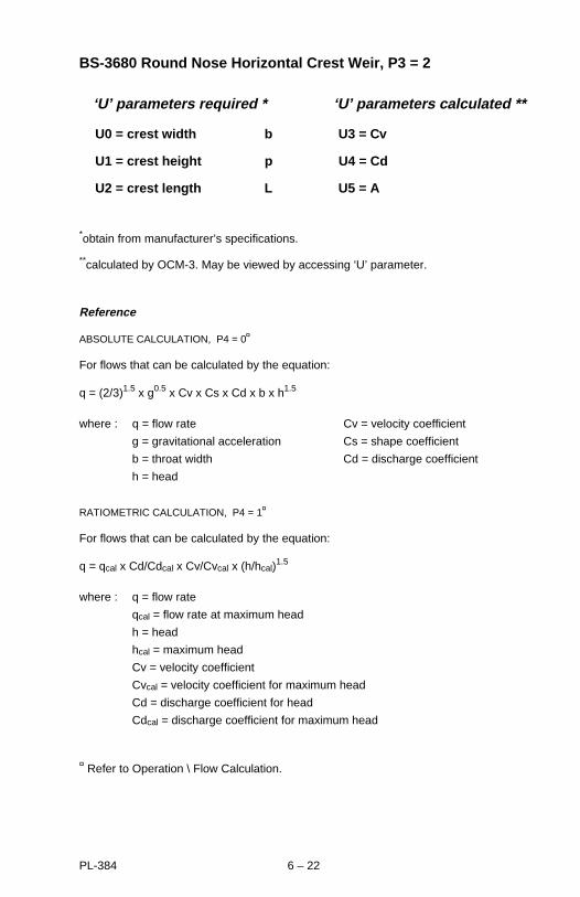
BS-3680 Round Nose Horizontal Crest Weir, P3 = 2
‘U’ parameters required * ‘U’ parameters calculated **
U0 = crest width b U3 = Cv
U1 = crest height p U4 = Cd
U2 = crest length L U5 = A
*obtain from manufacturer’s specifications.
**calculated by OCM-3. May be viewed by accessing ‘U’ parameter.
Reference
ABSOLUTE CALCULATION, P4 = 0¤
For flows that can be calculated by the equation:
q = (2/3)1.5 x g0.5 x Cv x Cs x Cd x b x h1.5
where : q = flow rate Cv = velocity coefficient
g = gravitational acceleration Cs = shape coefficient
b = throat width Cd = discharge coefficient
h = head
RATIOMETRIC CALCULATION, P4 = 1¤
For flows that can be calculated by the equation:
q = qcal x Cd/Cdcal x Cv/Cvcal x (h/hcal)1.5
where : q = flow rate
qcal = flow rate at maximum head
h = head
hcal = maximum head
Cv = velocity coefficient
Cvcal = velocity coefficient for maximum head
Cd = discharge coefficient for head
Cdcal = discharge coefficient for maximum head
¤ Refer to Operation \ Flow Calculation.
PL-384 6 – 22

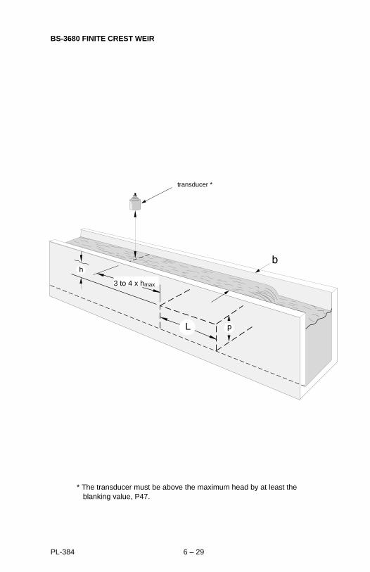
BS-3680 ROUND NOSE HORIZONTAL CREST WEIR
transducer *
3 to 4 x hmax
* The transducer must be above the maximum head by at least the blanking value, P47.
PL-384 6 – 23

BS-3680 TRAPEZOIDAL FLUME, P3 = 3
‘U’ parameters required * ‘U’ parameters calculated **
U0 = approach width B U5 = Cv
U1 = throat width b U6 = Cd
U2 = hump height p U7 = Cs
U3 = throat length L U8 = A
U4 = slope m
*obtain from manufacturer’s specifications.
**calculated by OCM-3. May be viewed by accessing ‘U’ parameter.
Reference
ABSOLUTE CALCULATION, P4 = 0¤
For flows that can be calculated by the equation:
q = (2/3)1.5 x g0.5 x Cv x Cs x Cd x b x h1.5
where : q = flow rate Cv = velocity coefficient
g = gravitational acceleration Cs = shape coefficient
b = throat width Cd = discharge coefficient
h = head
RATIOMETRIC CALCULATION, P4 = 1¤
For flows that can be calculated by the equation:
q = qcal x Cs/Cscal x Cd/Cdal x Cv/Cvcal x (h/hcal)1.5
where :
q = flow rate Cscal = shape coefficient for maximum head
qcal = flow rate at maximum head Cv = velocity coefficient
h = head Cvcal = velocity coefficient for maximum head
hcal = maximum head Cd = discharge coefficient for head
Cs = shape coefficient for head Cdcal = discharge coefficient for maximum head
¤ Refer to Operation \ Flow Calculation.
PL-384 6 – 24

BS-3680 TRAPEZOIDAL FLUME
p
side
transducer *
plan
L
end
ph
B
3 to 4 x hmax
b
* The transducer must be above the maximum head by at least the blanking value, P47.
PL-384 6 – 25
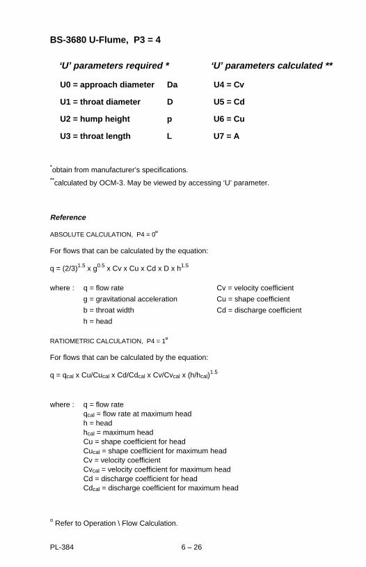
BS-3680 U-Flume, P3 = 4
‘U’ parameters required * ‘U’ parameters calculated **
U0 = approach diameter Da U4 = Cv
U1 = throat diameter D U5 = Cd
U2 = hump height p U6 = Cu
U3 = throat length L U7 = A
*obtain from manufacturer’s specifications.**calculated by OCM-3. May be viewed by accessing ‘U’ parameter.
Reference
ABSOLUTE CALCULATION, P4 = 0¤
For flows that can be calculated by the equation:
q = (2/3)1.5 x g0.5 x Cv x Cu x Cd x D x h1.5
where : q = flow rate Cv = velocity coefficient
g = gravitational acceleration Cu = shape coefficient
b = throat width Cd = discharge coefficient
h = head
RATIOMETRIC CALCULATION, P4 = 1¤
For flows that can be calculated by the equation:
q = qcal x Cu/Cucal x Cd/Cdcal x Cv/Cvcal x (h/hcal)1.5
where : q = flow rateqcal = flow rate at maximum headh = headhcal = maximum headCu = shape coefficient for headCucal = shape coefficient for maximum headCv = velocity coefficientCvcal = velocity coefficient for maximum headCd = discharge coefficient for headCdcal = discharge coefficient for maximum head
¤ Refer to Operation \ Flow Calculation.
PL-384 6 – 26

BS-3680 U-FLUME
L
ph
D
3 to 4 x hmax
93/05/31
Da
transducer *
0head
* The transducer must be above the maximum head by at least the blanking value, P47.
PL-384 6 – 27

BS-3680 FINITE CREST WEIR, P3 = 5
‘U’ parameters required * ‘U’ parameters calculated **
U0 = crest width b U3 = C
U1 = crest height p U4 = Cp
U2 = crest length L
*obtain from manufacturer’s specifications.
**calculated by OCM-3. May be viewed by accessing ‘U’ parameter.
Reference
ABSOLUTE CALCULATION, P4 = 0¤
For flows that can be calculated by the equation:
q = (2/3)1.5 x g0.5 x C x Cp x b x h1.5
where : q = flow rate C = a function of h and Lg = gravitational accelerationb = crest width Cp = a correction factor as a functionh = head of h and p applied to C
RATIOMETRIC CALCULATION, P4 = 1¤
For flows that can be calculated by the equation:
q = qcal x C/Ccal x Cp/Cpcal x (h/hcal)1.5
where : q = flow rate
qcal = flow rate at maximum head
h = head
hcal = maximum head
C = discharge coefficient for head
Ccal = discharge coefficient for maximum head
Cp = correction factor for C
Cpcal = correction factor for Ccal
¤ Refer to Operation \ Flow Calculation.
PL-384 6 – 28
BS-3680 FINITE CREST WEIR
transducer *
3 to 4 x hmax
* The transducer must be above the maximum head by at least the blanking value, P47.
PL-384 6 – 29
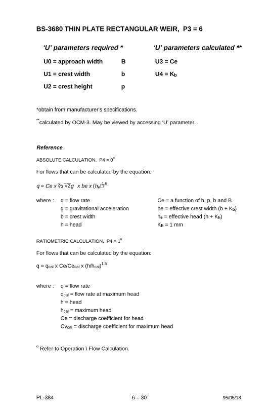
BS-3680 THIN PLATE RECTANGULAR WEIR, P3 = 6
‘U’ parameters required * ‘U’ parameters calculated **
U0 = approach width B U3 = Ce
U1 = crest width b U4 = K b
U2 = crest height p
*obtain from manufacturer’s specifications.
**calculated by OCM-3. May be viewed by accessing ‘U’ parameter.
Reference
ABSOLUTE CALCULATION, P4 = 0¤
For flows that can be calculated by the equation:
q = Ce x 2⁄3 √2g x be x (he)1.5
where : q = flow rate Ce = a function of h, p, b and B
g = gravitational acceleration be = effective crest width (b + Kb)
b = crest width he = effective head (h + Kh)
h = head Kh = 1 mm
RATIOMETRIC CALCULATION, P4 = 1¤
For flows that can be calculated by the equation:
q = qcal x Ce/Cecal x (h/hcal)1.5
where : q = flow rate
qcal = flow rate at maximum head
h = head
hcal = maximum head
Ce = discharge coefficient for head
Cvcal = discharge coefficient for maximum head
¤ Refer to Operation \ Flow Calculation.
95/05/18PL-384 6 – 30

BS-3680 THIN PLATE RECTANGULAR WEIR
4 to 5 x hmax
transducer *
* The transducer must be above the maximum head by at least the blanking value, P47.
PL-384 6 – 31
BS-3680 THIN PLATE V-NOTCH WEIR, P3 = 7
‘U’ parameters required * ‘U’ parameters calculated **
U0 = notch angle alpha U1 = Ce
*obtain from manufacturer’s specifications.
**calculated by OCM-3. May be viewed by accessing ‘U’ parameter.
Reference
ABSOLUTE CALCULATION, P4 = 0¤
For flows that can be calculated by the equation:
q = Ce x 8/15 x tan(α/2) x g0.5 x h2.5
where : q = flow rate h = head
g = gravitational acceleration Ce = function of h and αα = notch angle alpha◊
◊ angle is restricted to 90°, 53.133° or 28.066°. Otherwise use ratiometric calculation.
RATIOMETRIC CALCULATION, P4 = 1¤
For flows that can be calculated by the equation:
q = qcal x Ce/Cecal x (h/hcal)2.5
where : q = flow rate
qcal = flow rate at maximum head
h = head
hcal = maximum head
Ce = discharge coefficient for head
Cecal = discharge coefficient for maximum head
¤ Refer to Operation \ Flow Calculation.
PL-384 6 – 32
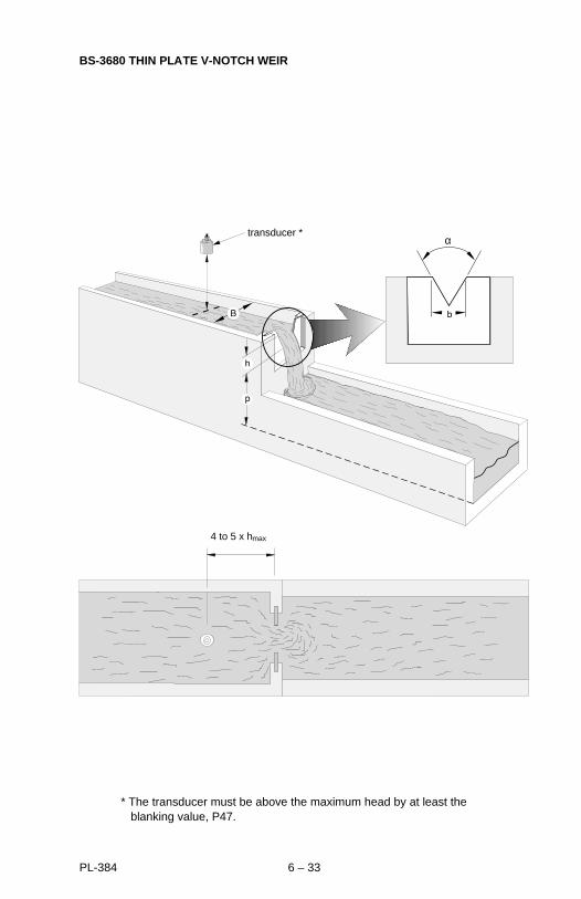
BS-3680 THIN PLATE V-NOTCH WEIR
transducer *
4 to 5 x hmax
α
* The transducer must be above the maximum head by at least the blanking value, P47.
PL-384 6 – 33
RECTANGULAR WEIR (CONTRACTED), P3 = 8
‘U’ parameters required *
U0 = crest width b
*obtain from manufacturer’s specifications.
**calculated by OCM-3. May be viewed by accessing ‘U’ parameter.
Reference
ABSOLUTE CALCULATION, P4 = 0¤
For flows that can be calculated by the equation:
q = K x (b - 0.2h) x h1.5
where : q = flow rate
h = head
K = constant
RATIOMETRIC CALCULATION, P4 = 1¤
For flows that can be calculated by the equation:
q = qcal x (b - 0.2h)/(b - 0.2hcal) x (h/hcal)2.5
where : q = flow rate
qcal = flow rate at maximum head
h = head
hcal = maximum head
¤ Refer to Operation \ Flow Calculation.
PL-384 6 – 34
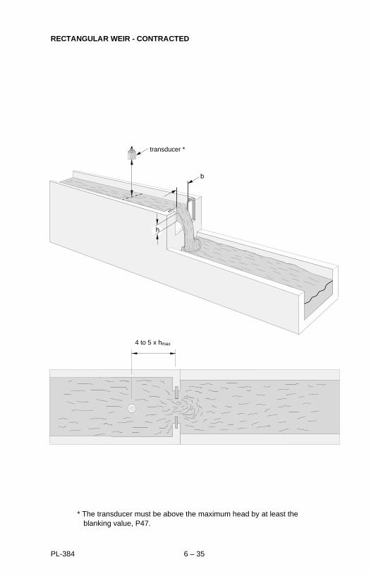
RECTANGULAR WEIR - CONTRACTED
transducer *
4 to 5 x hmax
* The transducer must be above the maximum head by at least the blanking value, P47.
PL-384 6 – 35

ROUND PIPE, P3 = 9
(based on the Manning Formula)
‘U’ parameters required *
U0 = pipe inside diameter D
U1 = slope (fall/run) s
U2 = roughness coefficientn
*obtain from manufacturer’s specifications.
Reference
ABSOLUTE CALCULATION, P4 = 0¤
For flows that can be calculated by the equation:
q = K/n x f(h) x s0.5
where : q = flow rate
h = head
K = constant
f(h) = A x R0.66
A = cross sectional area
R = hydraulic radius
s = slope of hydraulic gradient
n = roughness coefficient
RATIOMETRIC CALCULATION, P4 = 1¤
For flows that can be calculated by the equation:
q = qcal x f(h)/f(hcal)
where : q = flow rate h = head
qcal = flow rate at maximum head hcal = maximum head
¤ Refer to Operation \ Flow Calculation.
PL-384 6 – 36
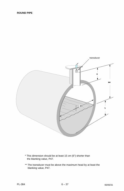
ROUND PIPE
h
transducer
*
**
* This dimension should be at least 15 cm (6") shorter than the blanking value, P47.
** The transducer must be above the maximum head by at least the blanking value, P47.
93/05/31PL-384 6 – 37

PALMER-BOWLUS FLUME *, P3 = 10
‘U’ parameters required **
U0 = maximum listed head, h max
*typically those manufactured by Warminster or Plasti-Fab.
**obtain from manufacturer’s specifications.
Reference
RATIOMETRIC CALCULATION, P4 = 1¤
For flows that can be calculated by the equation:
q = qcal x f(h/hmax) / f(hcal/hmax)
where : q = flow rate
qcal = flow rate at maximum head
h = head
hcal = maximum head
f(h/hmax) is determined by polynomial synthesis
¤ Refer to Operation \ Flow Calculation.
PL-384 6 – 38
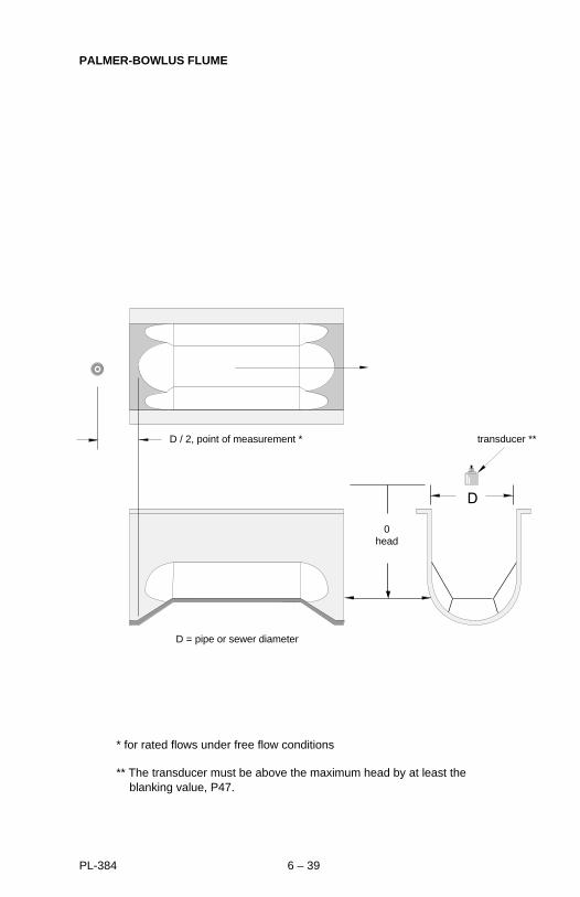
PALMER-BOWLUS FLUME
D = pipe or sewer diameter
0head
D / 2, point of measurement * transducer **
* for rated flows under free flow conditions
** The transducer must be above the maximum head by at least the blanking value, P47.
PL-384 6 – 39

H-FLUME *, P3 = 11
‘U’ parameters required *
U0 = maximum listed head, h max
*as developed by the U.S. Department of Agriculture, Soil Conservation Service.
**obtain from manufacturer’s specifications.
Reference
RATIOMETRIC CALCULATION, P4 = 1¤
For flows that can be calculated by the equation:
q = qcal x f(h/hmax)/f(hcal/hmax)
where : q = flow rate
qcal = flow rate at maximum head
f(h/hmax) and f(hcal/hmax) are determined by polynomial synthesis
¤ Refer to Operation \ Flow Calculation.
PL-384 6 – 40
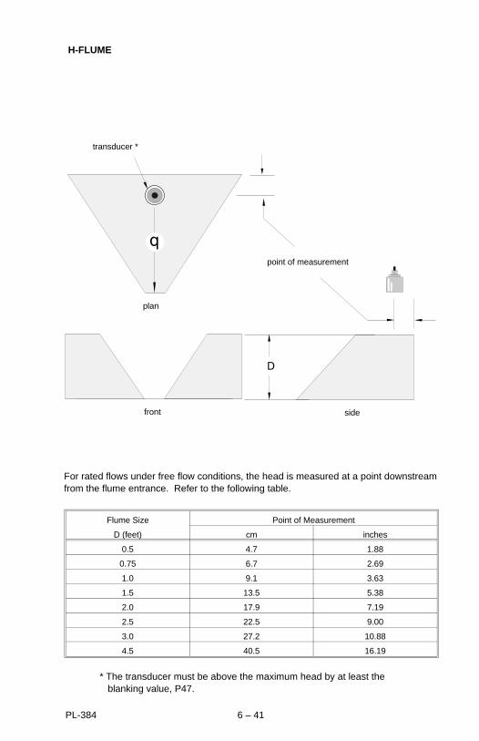
H-FLUME
front
point of measurement
side
transducer *
plan
Flume Size Point of Measurement
D (feet) cm inches
0.5 4.7 1.88
0.75 6.7 2.69
1.0 9.1 3.63
1.5 13.5 5.38
2.0 17.9 7.19
2.5 22.5 9.00
3.0 27.2 10.88
4.5 40.5 16.19
For rated flows under free flow conditions, the head is measured at a point downstreamfrom the flume entrance. Refer to the following table.
* The transducer must be above the maximum head by at least the blanking value, P47.
PL-384 6 – 41
UNIVERSAL HEAD vs FLOW, P3 = 12
The flow curve is characterized by entering the head (Aeven) and flow (Aodd) ordinates for the number of data points (n, 4 to 16) over the flow range. The first point (A0,A1) generally being at 0 head and the last point (A2n-2,A2n-1) generally beingat maximum head .
‘U’ parameters required *
U0 = number of data points (n, 4 to 16)
Aeven = headAodd = flow rate
*obtain from manufacturer’s specifications.
Reference
RATIOMETRIC CALCULATION, P4 = 1¤
For flows that can be calculated by the equation:
q = qcal x f(h)/f(hcal)
where : f(h) and f(hcal) are polynomials based on interpolation of data points
¤ Refer to Operation \ Flow Calculation.
PL-384 6 – 42
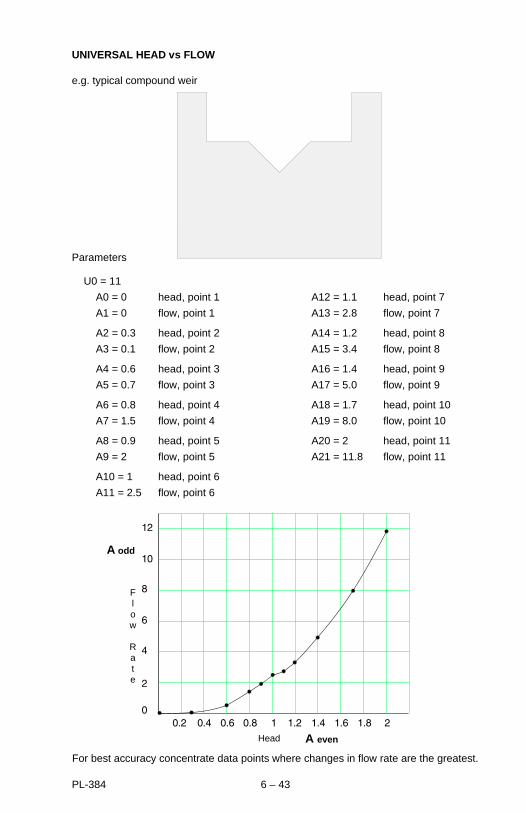
UNIVERSAL HEAD vs FLOW
e.g. typical compound weir
Parameters
U0 = 11
A0 = 0 head, point 1 A12 = 1.1 head, point 7
A1 = 0 flow, point 1 A13 = 2.8 flow, point 7
A2 = 0.3 head, point 2 A14 = 1.2 head, point 8
A3 = 0.1 flow, point 2 A15 = 3.4 flow, point 8
A4 = 0.6 head, point 3 A16 = 1.4 head, point 9
A5 = 0.7 flow, point 3 A17 = 5.0 flow, point 9
A6 = 0.8 head, point 4 A18 = 1.7 head, point 10
A7 = 1.5 flow, point 4 A19 = 8.0 flow, point 10
A8 = 0.9 head, point 5 A20 = 2 head, point 11
A9 = 2 flow, point 5 A21 = 11.8 flow, point 11
A10 = 1 head, point 6
A11 = 2.5 flow, point 6
Head A even
A odd
Flow
Rate
For best accuracy concentrate data points where changes in flow rate are the greatest.
PL-384 6 – 43
RECTANGULAR AREA X VELOCITY, P3 = 13
‘U’ parameters required * ‘U’ parameters calculated **
U0 = channel width B U1 = area (h)
*obtain from manufacturer’s specifications.
**calculated by OCM-3. May be viewed by accessing ‘U’ parameter.
Reference
ABSOLUTE CALCULATION, P4 = 0¤
For flows that can be calculated by the equation:
q = 1/1000 x B x h x V
where : q = flow rate in l/sec
B = channel width in cm
h = head in cm
V = velocity in cm/sec
RATIOMETRIC CALCULATION, P4 = 1¤
For flows that can be calculated by the equation:
q = qcal x A/Acal x v/vcal
where : q = flow rate
qcal = flow rate at maximum head
h = head
hcal = maximum head
v = velocity
vcal = velocity at maximum head
¤ Refer to Operation \ Flow Calculation.
PL-384 6 – 44
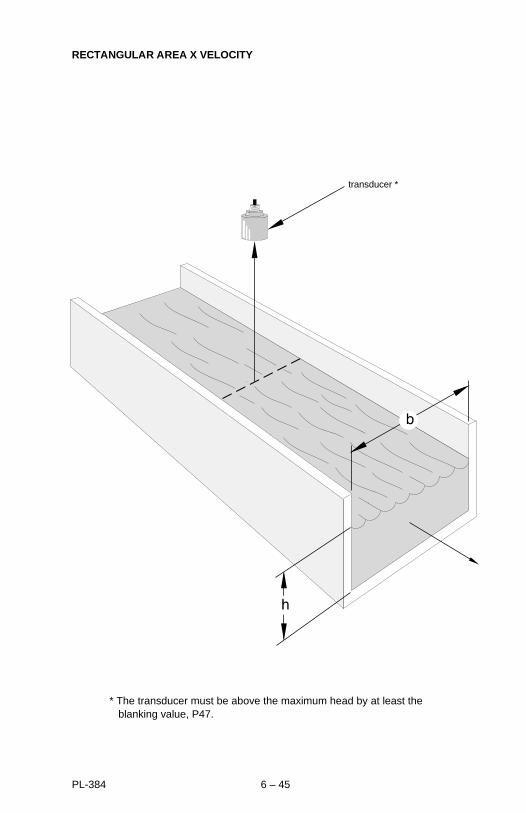
RECTANGULAR AREA X VELOCITY
transducer *
* The transducer must be above the maximum head by at least the blanking value, P47.
PL-384 6 – 45

TRAPEZOIDAL AREA X VELOCITY, P3 = 14
‘U’ parameters required * ‘U’ parameters calculated **
U0 = channel top width B U3 = area (h)
U1 = channel base width b
U2 = channel depth ht
*obtain from manufacturer’s specifications.
**calculated by OCM-3. May be viewed by accessing ‘U’ parameter.
Reference
ABSOLUTE CALCULATION, P4 = 0¤
For flows that can be calculated by the equation:
q = 1/1000 x (b + mh) x v
m = (B - b)/d
where : q = flow rate, l/secB = channel top width, cmb = channel bottom width, cmd = depth of channel, cmh = head, cmv = flow velocity, cm/sec
RATIOMETRIC CALCULATION, P4 = 1¤
For flows that can be calculated by the equation:
q = qcal x A/Acal x v/vcal
A = (b + mh) x h
Acal = (b + mhcal) x hcal
m = (B - b)/d
where : q = flow rate, l/secB = channel top width, cmb = channel bottom width, cmd = depth of channel, cmh = head, cmv = flow velocity, cm/sec
¤ Refer to Operation \ Flow Calculation.
PL-384 6 – 46

TRAPEZOIDAL AREA X VELOCITY
transducer *
* The transducer must be above the maximum head by at least the blanking value, P47.
PL-384 6 – 47
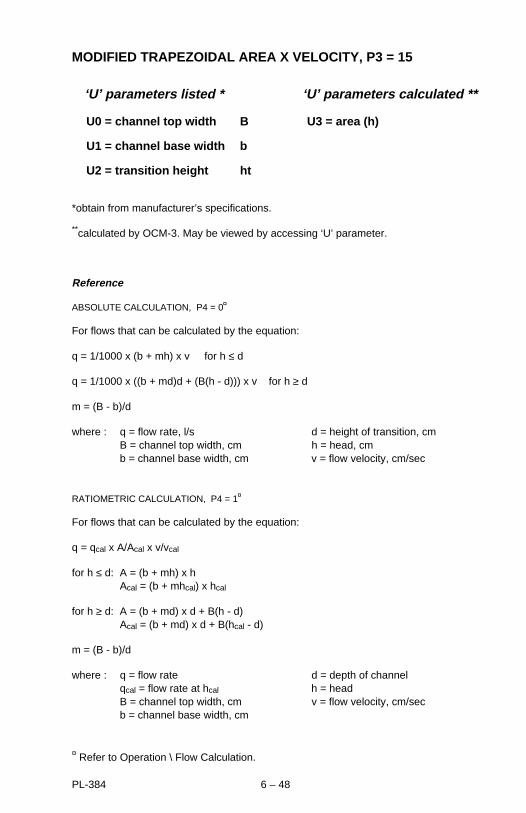
MODIFIED TRAPEZOIDAL AREA X VELOCITY, P3 = 15
‘U’ parameters listed * ‘U’ parameters calculated **
U0 = channel top width B U3 = area (h)
U1 = channel base width b
U2 = transition height ht
*obtain from manufacturer’s specifications.
**calculated by OCM-3. May be viewed by accessing ‘U’ parameter.
Reference
ABSOLUTE CALCULATION, P4 = 0¤
For flows that can be calculated by the equation:
q = 1/1000 x (b + mh) x v for h ≤ d
q = 1/1000 x ((b + md)d + (B(h - d))) x v for h ≥ d
m = (B - b)/d
where : q = flow rate, l/s d = height of transition, cmB = channel top width, cm h = head, cmb = channel base width, cm v = flow velocity, cm/sec
RATIOMETRIC CALCULATION, P4 = 1¤
For flows that can be calculated by the equation:
q = qcal x A/Acal x v/vcal
for h ≤ d: A = (b + mh) x h Acal = (b + mhcal) x hcal
for h ≥ d: A = (b + md) x d + B(h - d)Acal = (b + md) x d + B(hcal - d)
m = (B - b)/d
where : q = flow rate d = depth of channelqcal = flow rate at hcal h = headB = channel top width, cm v = flow velocity, cm/secb = channel base width, cm
¤ Refer to Operation \ Flow Calculation.
PL-384 6 – 48

MODIFIED TRAPEZOIDAL AREA X VELOCITY
transducer *
* The transducer must be above the maximum head by at least the blanking value, P47.
PL-384 6 – 49

U-CHANNEL AREA X VELOCITY, P3 = 16
‘U’ parameters required * ‘U’ parameters calculated **
U0 = base diameter D U1 = area (h)
*obtain from manufacturer’s specifications.
**calculated by OCM-3. May be viewed by accessing ‘U’ parameter.
PL-384 6 – 50
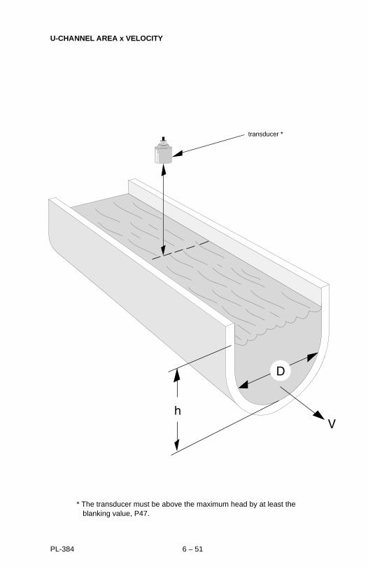
U-CHANNEL AREA x VELOCITY
transducer *
* The transducer must be above the maximum head by at least the blanking value, P47.
PL-384 6 – 51

CIRCULAR AREA X VELOCITY, P3 = 17
‘U’ parameters listed * ‘U’ parameters calculated **
U0 = conduit diameter ID U1 = area (h)
*obtain from manufacturer’s specifications.
**calculated by OCM-3. May be viewed by accessing ‘U’ parameter.
PL-384 6 – 52
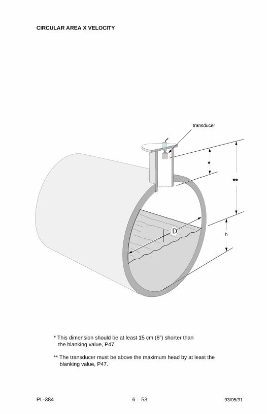
CIRCULAR AREA X VELOCITY
h
transducer
*
**
93/05/31
* This dimension should be at least 15 cm (6") shorter than the blanking value, P47.
** The transducer must be above the maximum head by at least the blanking value, P47.
PL-384 6 – 53

GULL-WING AREA X VELOCITY, P3 = 18
‘U’ parameters required * ‘U’ parameters calculated **
U0 = channel base width b U4 = area (h)
U1 = lower angle alpha (α)
U2 = upper angle beta (β)
U3 = transition height ht
*obtain from manufacturer’s specifications.
**calculated by OCM-3. May be viewed by accessing ‘U’ parameter.
PL-384 6 – 54

GULL WING AREA X VELOCITY
93/05/31
β
α
transducer *
V
* The transducer must be above the maximum head by at least the blanking value, P47.
PL-384 6 – 55
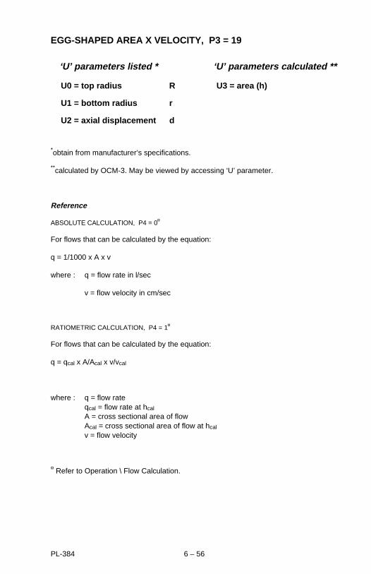
EGG-SHAPED AREA X VELOCITY, P3 = 19
‘U’ parameters listed * ‘U’ parameters calculated **
U0 = top radius R U3 = area (h)
U1 = bottom radius r
U2 = axial displacement d
*obtain from manufacturer’s specifications.
**calculated by OCM-3. May be viewed by accessing ‘U’ parameter.
Reference
ABSOLUTE CALCULATION, P4 = 0¤
For flows that can be calculated by the equation:
q = 1/1000 x A x v
where : q = flow rate in l/sec
v = flow velocity in cm/sec
RATIOMETRIC CALCULATION, P4 = 1¤
For flows that can be calculated by the equation:
q = qcal x A/Acal x v/vcal
where : q = flow rateqcal = flow rate at hcal
A = cross sectional area of flowAcal = cross sectional area of flow at hcal
v = flow velocity
¤ Refer to Operation \ Flow Calculation.
PL-384 6 – 56

EGG-SHAPED AREA X VELOCITY
transducer *
standpipe **
* This dimension should be at least 15 cm (6") shorter than the blanking value, P47.
** The transducer must be above the maximum head by at least the blanking value, P47.
93/05/31PL-384 6 – 57
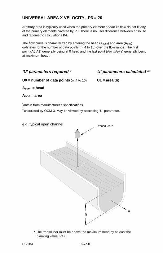
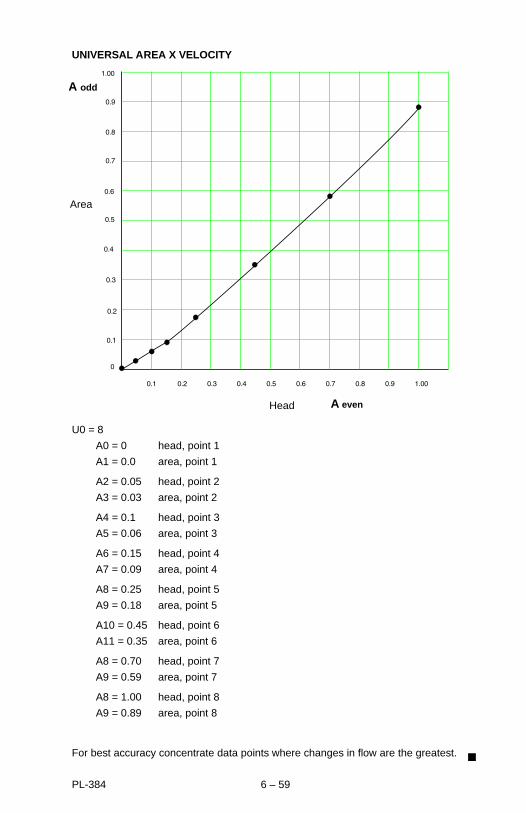
UNIVERSAL AREA X VELOCITY, P3 = 20
Arbitrary area is typically used when the primary element and/or its flow do not fit anyof the primary elements covered by P3. There is no user difference between absoluteand ratiometric calculations P4.
The flow curve is characterized by entering the head (Aeven) and area (Aodd) ordinates for the number of data points (n, 4 to 16) over the flow range. The first point (A0,A1) generally being at 0 head and the last point (A2n-2,A2n-1) generally beingat maximum head .
‘U’ parameters required * ‘U’ parameters calculated **
U0 = number of data points (n, 4 to 16) U1 = area (h)
Aeven = head
Aodd = area
*obtain from manufacturer’s specifications.**calculated by OCM-3. May be viewed by accessing ‘U’ parameter.
e.g. typical open channel transducer *
* The transducer must be above the maximum head by at least the blanking value, P47.
PL-384 6 – 58
UNIVERSAL AREA X VELOCITY
U0 = 8
A0 = 0 head, point 1
A1 = 0.0 area, point 1
A2 = 0.05 head, point 2
A3 = 0.03 area, point 2
A4 = 0.1 head, point 3
A5 = 0.06 area, point 3
A6 = 0.15 head, point 4
A7 = 0.09 area, point 4
A8 = 0.25 head, point 5
A9 = 0.18 area, point 5
A10 = 0.45 head, point 6
A11 = 0.35 area, point 6
A8 = 0.70 head, point 7
A9 = 0.59 area, point 7
A8 = 1.00 head, point 8
A9 = 0.89 area, point 8
For best accuracy concentrate data points where changes in flow are the greatest.
A odd
A even
Head
Area
PL-384 6 – 59

MAINTENANCE
If the OCM-3 must be opened to perform any maintenance functions, the powershould be disconnected at the main breaker and locked out to prevent personnelinjury and equipment damage. Keep in mind that relay and mA outputs, andcommunications will be affected.
The OCM-3 requires very little maintenance due to its solid-state circuitry. However, aprogram of periodic preventative maintenance should be initiated. This should includeregular inspection, general cleaning, overall system performance checks and standardgood housekeeping practices.
A periodic inspection of the transducer is recommended, at which time any build-up ofmaterial on the face should be removed.
The enclosure and circuit board should be cleaned using a vacuum cleaner and aclean, dry brush. Check all electrical contacts for signs of corrosion or arcing.
The memory battery, B1, (see Specifications and Installation) should be replacedyearly to insure memory back up during lengthy power outages. An on boardcapacitor provides one hour of memory retention in order to preserve the memorywhile the battery is being changed.
PL-384 7 – 1
ERROR CODES
Error Code Listing
1 number underflow
2 number overflow
3 divide error
4 bad argument
5 invalid parameter
6 system is locked
7 head exceeds BS-3680 spec
8 must use ratiometric
9 invalid angle size
10 invalid selection
11 value is view-only
12 characterizer in use
13 feature not available
14 need whole number
15 invalid date
16 invalid time
20 can’t zero auxiliary device
21 b must be greater than R-r
PL-384 7 – 2

COMMUNICATIONS
The OCM-3 provides serial communication either through Milltronics proprietarybipolar current loop or industry standard RS-232. Communication can be used toprovide a video or paper printout of OCM activity. It can also be used to provideremote programming and retrieval of the data log, from devices such as computersand PLCs.
When using the bipolar current loop, communication runs of up to 1,500 m can beachieved, as opposed to the limited runs of 15 m using RS-232. By terminating thebipolar current loop with a Milltronics CVCC, the communication format is thenconverted to RS-232.
* Milltronics OCM -3 Utilities Software available
** provides conversion to RS -232 or 422
RS-232
customer’scomputer *
CVCC **
optional parallel printerserial printer
customer’scomputer *
bipolar current loop
OCM - 3site number(P39 )
PL-384 7 – 3

Milltronics provides a standard Utilities software package, for convenientcommunication between an IBM PC compatible computer and the OCM-3. In addition,the user may opt to develop his own custom software program to perform tasks suitedto his specific needs.
Protocol
The protocol for the OCM-3 is as follows:
baud rate: set via P37
parity: none
stop bits: 1
word length: 8
The OCM-3 uses a three wire XON/XOFF serial communication link. When theOCM-3’s receive buffer is near full, the OCM-3 sends an XOFF signal to tell thesender of the near full condition.
If the sender is also using XON/XOFF, it will respond to the XOFF signal bysuspending its transmission.
Similarly, when the OCM-3 receive buffer is near empty, the OCM-3 sends an XONsignal to tell the sender that it is safe to resume sending.
The communication baud rate of the OCM-3 and its correspondent must be the same.
PL-384 7 – 4

Interconnection
Bipolar Current
RS-232
IBM PC Computer Connection
* handshaking jumpers may be required when communicating with softwareother than Milltronics OCM - 3 standard Utilities package.
refer to CVCCinstructionmanual forconnection tocomputer
computer serial port
DB-9 connector
93/04/26
computer serial port
DB-25 connector
PL-384 7 – 5
Timed Print Out
The OCM-3 can be programmed to periodically print out OCM data (P34/35). A typicalprint out will have the following format.
Time hh:mm:ss
Date dd/mm/yy
Site Number #
Head # units
Velocity* # units
Temperature # units
Flow Rate # units
Flow Total # units
*only for applications using velocity input
When the output is directed to a serial printer, a delay is inserted between each line toallow the printer time to print each line before another is sent. In that way, the simplestof printers may be used without need of XON/OFF or hardware handshaking; only athree wire connection is required. The printer must be at least 40 columns wide. TheOCM-3 sends text in upper and lower case. The printer must support both upper andlower case or else treat lower case as if it had been sent in upper case.
The printing interval must divide evenly into the selected units of time for printing tooccur at regular intervals.
e.g. P34 = 1, printer mode set for interval in minutes
P35 = 7, print interval set for 7 minutes
Printing starts at 7 minutes after the hour and will occur every 7 minutes thereafter until 56 minutes into the hour. The next print out would not occur until 7 minutes into the next hour.
Since the port used for communication is the same as used for normal serialcommunication, a software switch controls whether or not the display is sent out onthe serial port. The switch is controlled by typing ’v’ to allow data transmission or ’w’ tostop it. The Milltronics printer emulation program does this automatically.
If the OCM-3 is connected to a computer programmed for printer emulation, thecomputer will receive the print out data and display it on the video terminal (refer toMilltronics Utilities Software).
PL-384 7 – 6

Milltronics Utilities Software Disk
The Milltronics Utilities Software expands the human interface capabilities of theOCM-3 as compared to that provided by the simple use of the infra-red programmer.
Utilities Software Programmer
- remote OCM-3 programming - local programming
- remote OCM-3 display - local display
- saving OCM-3 program parameters
- retrieving log data
- creating spread sheet data log file
- creating ASCII text data log file
- emulating serial printer
- graphic flow rate display
PL-384 7 – 7
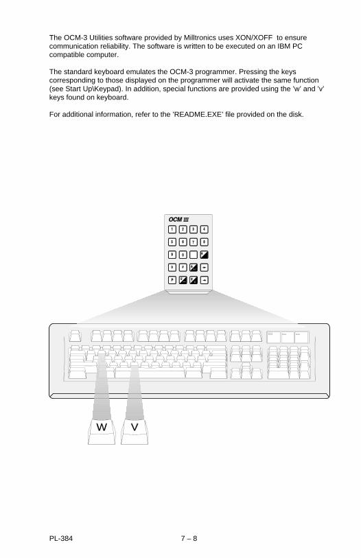
The OCM-3 Utilities software provided by Milltronics uses XON/XOFF to ensurecommunication reliability. The software is written to be executed on an IBM PCcompatible computer.
The standard keyboard emulates the OCM-3 programmer. Pressing the keyscorresponding to those displayed on the programmer will activate the same function(see Start Up\Keypad). In addition, special functions are provided using the ’w’ and ’v’keys found on keyboard.
For additional information, refer to the ’README.EXE’ file provided on the disk.
W V
PL-384 7 – 8
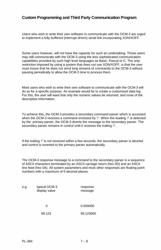
Custom Programming and Third Party Communication Program
Users who wish to write their own software to communicate with the OCM-3 are urgedto implement a fully buffered (interrupt driven) serial link incorporating XON/XOFF.
Some users however, will not have the capacity for such an undertaking. Those usersmay still communicate with the OCM-3 using the less sophisticated communicationcapabilities provided by such high level languages as Basic, Pascal or C. The onlyrestriction imposed by using a system that does not use XON/XOFF, is that the usermust insure that he does not send long streams of commands to the OCM-3 withoutpausing periodically to allow the OCM-3 time to process them.
Most users who wish to write their own software to communicate with the OCM-3 willdo so for a specific purpose. An example would be to create a customized data log.For this, the user will want that only the numeric values be returned, and none of thedescriptive information.
To achieve this, the OCM-3 provides a secondary command parser which is accessedwhen the OCM-3 receives a command enclosed by ‘/’. When the leading ‘/’ is detectedby the primary parser, the OCM-3 diverts the message to the secondary parser. Thesecondary parser remains in control until it receives the trailing ‘/’.
If the trailing ‘/’ is not received within a few seconds, the secondary parser is abortedand control is reverted to the primary parser automatically.
The OCM-3 response message to a command to the secondary parser is a sequenceof ASCII characters terminated by an ASCII carriage return (hex 0D) and an ASCIIline feed (hex 0A). All system parameters and most other responses are floating pointnumbers with a maximum of 6 decimal places.
e.g. typical OCM-3 response display value message
0 0.000000
99.123 99.123000
PL-384 7 – 9
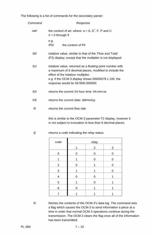
The following is a list of commands for the secondary parser:
Command Response
/a#/ the content of a#, where: a = A, D*, F, P and U# = 0 through 9
e.g./P5/ the content of P5
/t0/ totalizer value, similar to that of the ‘Flow and Total’(F2) display, except that the multiplier is not displayed
/t1/ totalizer value, returned as a floating point number with a maximum of 6 decimal places, modified to include the effect of the totalizer multiplier. e.g. if the OCM-3 display shows 00005678 x 100, the response would be 567800.000000
/t2/ returns the current 24 hour time: hh:mm:ss
/t3/ returns the current date: dd/mm/yy
/f/ returns the current flow rate
this is similar to the OCM-3 parameter F2 display, however it is not subject to truncation to less than 6 decimal places.
/j/ returns a code indicating the relay status
/l/ fetches the contents of the OCM-3’s data log. The command sets a flag which causes the OCM-3 to send information a piece at a time in order that normal OCM-3 operations continue during the transmission. The OCM-3 clears the flag once all of the information has been transmitted.
code relay
1 2 3
0 0 0 0
1 1 0 0
2 0 1 0
3 1 1 0
4 0 0 1
5 1 0 1
6 0 1 1
7 1 1 1
PL-384 7 – 10
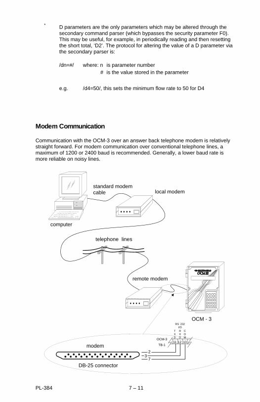
* D parameters are the only parameters which may be altered through the secondary command parser (which bypasses the security parameter F0). This may be useful, for example, in periodically reading and then resetting the short total, ‘D2’. The protocol for altering the value of a D parameter via the secondary parser is:
/dn=#/ where: n is parameter number # is the value stored in the parameter
e.g. /d4=50/, this sets the minimum flow rate to 50 for D4
Modem Communication
Communication with the OCM-3 over an answer back telephone modem is relativelystraight forward. For modem communication over conventional telephone lines, amaximum of 1200 or 2400 baud is recommended. Generally, a lower baud rate ismore reliable on noisy lines.
local modem
computer
standard modemcable
OCM - 3
modem
DB-25 connector
telephone lines
COM
RXD
TXD
RS 232I/O
11
23
7
OCM-3
TB-112 13
remote modem
PL-384 7 – 11

The Milltronics Utilities software can be run via modem. In addition the TerminalEmulation program of the Utilities software package can be used to send controlsequences directly to the modem.
The remote modem is defined as the modem connected to the OCM-3. The localmodem is defined as the modem connected to the computer.
It should be noted that the modem responses listed in the following discussion serveonly to typify what is presently common in current field of RS-232 communication.
Considerations
- set the ’cold start’ (F12) default baud to 1200 by removing jumper J1 on board A.
- set both modems and the OCM-3 baud rates to 1200.
- set the remote modem to operate in the ’answer back’ mode. Refer to modem’s user manual.
Communication
- select Terminal Emulation program. See Milltronics Utilities Software Disk.
The computer screen will display the letters ’v’. These would normally have gone to the OCM-3 to ask it to send its display, but the modem will have returned it to the screen instead.
- type the following:
ATD and the telephone number of the remote modem, then press ‘ENTER’.
The modem will dial the number you have entered. When the localmodem establishes contact with the remote modem, the local modem sends a message to the screen (typical).
CONNECT
- press the ‘v’ and ‘ENTER’ keys to turn on the OCM-3’s display-to-serial channel.
The OCM-3 is now on line and communication can be carried out. The user may escape to the main menu of the Utilities software and select another program if so desired.
To close the communication, return to the Terminal Emulation program.
93/04/26PL-384 7 – 12

- type: +++ (not displayed on the screen) and then press ENTER
This will cause both modems to switch to the ‘command’ mode. The local modem sends a message to the screen (typical).
OK
- type: ATH and press the ENTER key.
Both modems will hang up. The local modem sends a message to the screen (typical).
OK
93/04/26
PL-384 7 – 13