On the Mathematics of Self-Assemblyspot.colorado.edu/~dure7259/papers/ReishusThesis.pdf · atomic...
175
ON THE MATHEMATICS OF SELF-ASSEMBLY by Dustin Reishus A Dissertation Presented to the FACULTY OF THE GRADUATE SCHOOL UNIVERSITY OF SOUTHERN CALIFORNIA In Partial Fulfillment of the Requirements for the Degree DOCTOR OF PHILOSOPHY (COMPUTER SCIENCE) August 2009 Copyright 2009 Dustin Reishus
Transcript of On the Mathematics of Self-Assemblyspot.colorado.edu/~dure7259/papers/ReishusThesis.pdf · atomic...

ON THE MATHEMATICS OF SELF-ASSEMBLY
by
Dustin Reishus
A Dissertation Presented to theFACULTY OF THE GRADUATE SCHOOL
UNIVERSITY OF SOUTHERN CALIFORNIAIn Partial Fulfillment of theRequirements for the Degree
DOCTOR OF PHILOSOPHY(COMPUTER SCIENCE)
August 2009
Copyright 2009 Dustin Reishus

Acknowledgments
It would not have been possible for me to get a PhD without the love, support, guidance,
and friendship I received from many, many people along the way. It is also not possible
for me to adequately express the gratitude I feel for everyone who helped me along the
way, nor is it possible for me to list everyone who deserves that gratitude, but that won’t
stop me from trying.
First, of course, comes my family; my father Allan, my mother Donna, my sister
Anna, and my brother-in-law Nick: From my earliest memories and throughout my life,
you’ve instilled in me the desire to learn, to know, to achieve. You are the reason I am
where I am today. I love you all.
My advisor Len: You’ve taught me more than just how to do experiments, how to
write papers, and how to do math. You’ve taught me how to think. You’ve helped me
with problems, both academic and personal. The mentor/mentee relationship may be
how we began, but now, and for all times, you are and will be my cherished friend.
My best friends and fellow PhD students, Yuriy and Dave: I literally don’t know
where I would be without you guys. We have had more good times than I can count. We
have had more fun than anyone could reasonably expect, but there have also been hard
times. Thank you guys for sharing with me the good times; thank you for being there for
ii

me through the bad times; thank you for helping me with research; thank you for being
my friends.
My good friends The Robots; Brian, Justin, David, Mike, Josh, the other Mike, and
Dominic: Living with you guys through college and in the Robot House is one of the best
things I’ve ever done in my life. You made my undergraduate experience the happiest
period of my life and you all will be my life-long friends.
My friends and colleagues, Nickolas, Manoj, Bilal, Joe, Henry, and Urmila: For the
countless hours we spent in the lab doing experiments, or in meetings writing papers
and doing math; for the midnight conversations discussing the trickier points of algebraic
complex analysis; and for the times we’ve just hung out and discussed life; thank you.
My mentors, Paul, Ming, Steve, Lila, Ashish, and many others: You’ve given your
time, your expertise, your advice, and your guidance. I am forever grateful.
And finally, my teachers: To all my teachers and professors, thank you for the gift
of knowledge that you have given me. I will spend the rest of my life trying to pay it
forward.
iii

Table of Contents
Acknowledgments ii
List Of Figures vi
Abstract viii
Chapter 1: Introduction 1
Chapter 2: DNA Self-Assembly 52.1 Double-Double Crossover Complex . . . . . . . . . . . . . . . . . . . . 62.2 Triangular Complexes . . . . . . . . . . . . . . . . . . . . . . . . . . . 11
Chapter 3: Tile Assembly Model 163.1 Basic Definitions and Notation . . . . . . . . . . . . . . . . . . . . . . 193.2 A Directed Tile System with the Strong Plane-Filling Property . . . . 23
3.2.1 Generalized tile systems . . . . . . . . . . . . . . . . . . . . . . 253.2.2 Microtiles . . . . . . . . . . . . . . . . . . . . . . . . . . . . . . 273.2.3 Minitiles . . . . . . . . . . . . . . . . . . . . . . . . . . . . . . . 333.2.4 Macrotiles: The 3x3 block construction . . . . . . . . . . . . . 39
3.3 Undecidability of Existence of Infinite Ribbons . . . . . . . . . . . . . 493.4 Undecidability of Self-Assembly of Arbitrarily Large Supertiles . . . . 57
Chapter 4: Event-Systems Model 594.1 Basic Definitions and Notation . . . . . . . . . . . . . . . . . . . . . . 644.2 Finite Event-Systems . . . . . . . . . . . . . . . . . . . . . . . . . . . . 724.3 Finite Physical Event-Systems . . . . . . . . . . . . . . . . . . . . . . . 774.4 Finite Natural Event-Systems . . . . . . . . . . . . . . . . . . . . . . . 944.5 Finite Natural Atomic Event-Systems . . . . . . . . . . . . . . . . . . 124
Chapter 5: Zeta Event-Systems 1305.1 Riemann Zeta Function . . . . . . . . . . . . . . . . . . . . . . . . . . 1325.2 Basic Definitions and Notation . . . . . . . . . . . . . . . . . . . . . . 135
5.2.1 Pressure . . . . . . . . . . . . . . . . . . . . . . . . . . . . . . . 1385.2.2 Temperature . . . . . . . . . . . . . . . . . . . . . . . . . . . . 1395.2.3 Processes . . . . . . . . . . . . . . . . . . . . . . . . . . . . . . 141
5.3 Zeta Event-Systems . . . . . . . . . . . . . . . . . . . . . . . . . . . . 1435.4 Visualizing Event-Processes . . . . . . . . . . . . . . . . . . . . . . . . 151
iv

5.5 Numerical Simulations of Event Processes . . . . . . . . . . . . . . . . 1555.6 Discussion . . . . . . . . . . . . . . . . . . . . . . . . . . . . . . . . . . 157
References 158
v

List Of Figures
Figure 2.1: DNA double-double crossover (DDX) complex . . . . . . . . . . 7
Figure 2.2: Atomic force micrographs of DDX structures . . . . . . . . . . . 9
Figure 2.3: Diagram of an alternative DDX complex . . . . . . . . . . . . . 9
Figure 2.4: Diagram of the four-helix bundle complex . . . . . . . . . . . . 10
Figure 2.5: Diagram of a triangular complex . . . . . . . . . . . . . . . . . . 12
Figure 2.6: Atomic force micrographs of triangular complexes . . . . . . . . 13
Figure 3.1: The five types of microtiles . . . . . . . . . . . . . . . . . . . . . 28
Figure 3.2: Labeling mixed arms . . . . . . . . . . . . . . . . . . . . . . . . 28
Figure 3.3: The (2n+1 − 1)-XY -square . . . . . . . . . . . . . . . . . . . . . 30
Figure 3.4: The 7-XY -square . . . . . . . . . . . . . . . . . . . . . . . . . . 31
Figure 3.5: Paths through 2n+1 × 2n+1 minitiles . . . . . . . . . . . . . . . 34
Figure 3.6: The paths A4 and A16 . . . . . . . . . . . . . . . . . . . . . . . 34
Figure 3.7: The labeling of mixed arms . . . . . . . . . . . . . . . . . . . . 36
Figure 3.8: The labeling of mixed arms (continued) . . . . . . . . . . . . . . 36
Figure 3.9: Directions assigned to minitiles . . . . . . . . . . . . . . . . . . 37
Figure 3.10: Microtiles, minitiles, and macrotiles . . . . . . . . . . . . . . . 39
Figure 3.11: Macrotile glues . . . . . . . . . . . . . . . . . . . . . . . . . . . 40
vi

Figure 3.12: The (2n+1 − 1)-square used in the proof of Lemma 3.2.6 . . . . 45
Figure 3.13: Pairs of macrotiles attached to S(1) and S(2) . . . . . . . . . . 47
Figure 3.14: A sandwich tile . . . . . . . . . . . . . . . . . . . . . . . . . . . 50
Figure 3.15: A ribbon motif . . . . . . . . . . . . . . . . . . . . . . . . . . . 52
Figure 3.16: Variant ribbon motifs . . . . . . . . . . . . . . . . . . . . . . . 53
Figure 3.17: The bump-and-dent pair that simulate a glue . . . . . . . . . . 54
Figure 5.1: Visualizing complex-valued functions of a complex variable usingdomain coloring . . . . . . . . . . . . . . . . . . . . . . . . . . . . . . . 152
Figure 5.2: Images of a simplified Eζ,2(s)-process . . . . . . . . . . . . . . . 153
Figure 5.3: Images of the numerical simulation of a Eζ,2(s)-process . . . . . 159
vii

Abstract
Self-assembly is the ubiquitous process by which simple objects come together under
simple rules to form more complex objects. Self-assembly occurs in nature to produce
structures of extraordinary complexity. In the future, it may be possible to harness the
power of self-assembly to manufacture useful devices in enormous quantities at little cost.
In order to do so, it would be valuable to have a deep understanding of self-assembly, at
both theoretical and practical levels.
I first describe experimental work with DNA self-assembly. DNA is an ideal substance
to use in experimental self-assembly: It has well-understood structure; it has readily-
available tools to synthesize, manipulate, and visualize it; and it has “programmable”
interactions with other molecules of DNA. I describe two self-assembling DNA complexes
that can further self-assemble into regular lattices.
Mathematical models of self-assembly have been created to aid in the analysis of the
power and limits of self-assembly. I explore decidability questions in a mathematical
model of self-assembly known as the tile assembly model. I prove the undecidability of
distinguishing self-assembling systems in which infinite structures can be assembled from
systems in which only finite structures can be assembled.
viii

Many self-assembly processes are rooted in chemistry. The event-systems model gen-
eralizes the classical theory of chemical thermodynamics and places the kinetic theory of
chemical reactions on a firm mathematical foundation. I prove that many of the expec-
tations acquired through empirical study are warranted.
Finally, I use the event-systems model to explore questions in pure mathematics. The
atomic hypothesis in chemistry (the theory that every substance is composed of a unique
set of atoms) is analogous to the fundamental theorem of arithmetic in mathematics
(the theory that every natural number is the product of a unique set of primes). I
exploit this analogy by creating event-systems in which the basic components are natural
numbers that can “react” through multiplication. Important thermodynamic properties
such as temperature and pressure have purely mathematical implications in these systems.
In particular, the pressure at equilibrium is the Riemann zeta function’s value of the
temperature of the system.
ix

Chapter 1
Introduction
Self-assembly is the ubiquitous process in which simple objects come together under
simple rules to form more complex objects. Examples of natural self-assembling systems
abound on all scales, from the microscopic to the cosmologic. At the tiniest scales,
subatomic particles self-assemble to form atoms, atoms self-assemble to form molecules,
and molecules self-assemble to form crystals. The simple rules these objects are following
are consequences of natural forces: the strong nuclear force and the electromagnetic force.
At the largest scales, stars self-assemble to form galaxies and galaxies self-assemble to
form galaxy clusters; consequences of the gravitational force.
In nature, self-assembly processes create intricate structures (such as the crystal struc-
ture of a snowflake) and practical structures (such as virus capsids). Recently it has been
suggested that complex self-assembly processes will ultimately be used in integrated cir-
cuit fabrication, nanorobotics, DNA computation and amorphous computing. Indeed, in
electronics, engineering, medicine, material science, manufacturing and other disciplines,
there is a continuous drive toward miniaturization. Unfortunately, current “top-down”
techniques such as lithography may not be capable of efficiently creating structures with
1

features the size of molecules or atoms. Self-assembly provides a “bottom-up” approach
by which such fine structures might be created.
Experimental research on self-assembly includes creation of Penrose tilings using
macroscopic plastic tiles that assemble at an oil/water interface [71], studies of self-
directed growth of hybrid organic molecules on a silicon substrate [58], self-assembly of
regular lipid hollow icosahedra [23], self-assembly of patterns of lead on a copper surface
with the goal of creating templates for fabricating nanostructures [64], formation of elec-
trical networks by self-assembly of small plastic and metal objects [37, 84], self-assembly
of molecular machines [35], the construction by self-assembly of a molecular-thickness
transistor [76], self-assembly of DNA nanomachines (e.g., molecular switches [55], tweez-
ers [91, 61], walkers [78], autonomous DNA motors [82, 11, 38]), as well as algorithmic
self-assembly of Sierpinski triangles [74], self-assembled cloneable DNA octahedra [79],
stiff self-assembled tetrahedra for three-dimensional electronic circuits [36], and DNA
origami [72].
Investigations into DNA Computing [2] and amorphous computing [1] have demon-
strated a strong connection between self-assembly and computation. While [88, 53, 67, 85]
have shown the potential of DNA self-assembly for computation, [59] has demonstrated
the execution of logical operations (cumulative XOR) by self-assembly of DNA triple
cross-over molecules and [12] has demonstrated the potential for programmable self-
assembled computing devices.
A deep understanding of self-assembly would be valuable in designing self-assembling
systems with desired properties. Mathematical models of self-assembly could help provide
this understanding. Hopefully these models of self-assembly processes abstract away
2
irrelevant details, leaving only the phenomena we wish to explore. Currently there are
several models of self-assembly, each looking at the processes in a slightly different way,
each abstracting out different details.
In the chapters that follow, I will explore both theoretical and experimental aspects
of self-assembly.
In Chapter 2, I will describe experimental work in DNA self-assembly that I have done
with my colleagues. DNA, as a material, has many properties that make it ideal to use
when exploring self-assembling systems. Its structure is well-understood. There are many
tools from molecular biology for creating, manipulating, and measuring it. It is cheap
to obtain in abundance. Most importantly, it has programmable interactions with other
molecules. By changing the sequence of nucleotides, it is possible to design a molecule
that sticks to another molecule in a particular way and with a particular strength.
In Chapter 3, I will explore a formal model of self-assembly known as the tile assembly
model (TAM). TAM was initially created to model the self-assembly of DNA complexes
such as the ones discussed in Chapter 2. Using a mathematical model of self-assembly
allows us to study the limits and power of self-assembly processes. In particular, I will
describe the work I have done with colleagues proving the undecidability of the problem
of distinguishing self-assembling systems in which infinite structures can be assembled
from systems in which only finite structures can be assembled.
In Chapter 4, I will explore a different model of self-assembly known as the event-
systems model (ESM). I, along with my colleagues, created ESM, which generalizes the
classical theory of chemical thermodynamics. Given a set of chemical reactions, the
theory of event-systems describes how to use the law of mass action to obtain a set of
3

differential equations that predict the concentrations of self-assembling species through
time. Using the model, I prove that, under certain conditions or assumptions, many of
the expectations acquired through empirical studies are justified.
In Chapter 5, I will describe a particular class of event-systems that I call zeta event-
systems. Unlike in classical thermodynamics, in the event-systems model the reaction
rates, concentrations, temperature, and even time can be complex-valued. These systems
are given in terms of a parameter s, and have the property that the total pressure or mass
of the system is ζ(s), where ζ is the Riemann zeta function. By studying the dynamics of
these systems, I hope to be able to better understand this very important mathematical
function.
4

Chapter 2
DNA Self-Assembly
In this chapter, we describe the double-double crossover complex and the triangular
complex. Each of these complexes self-assemble from molecules of DNA. The complexes
themselves serve as building blocks which can further self-assemble into regular lattices.
A preliminary description of this work appeared in [15] and later, in more detail, in [68]
and [16].
The field of human-designed, self-assembled DNA structures was initiated by Seeman
et al. [18]. In 1993, Fu et al. [31] described the double crossover (DX) complex consisting
of two DNA double helices connected by two reciprocal exchanges (crossovers). In 1998,
Winfree et al. [86] used DX complexes to self-assemble regular planar structures. Sub-
sequently, several other DNA complexes have been designed and used to self-assemble
organized structures [52, 89].
5

2.1 Double-Double Crossover Complex
In this section, we present a new complex based on the DX, the double-double crossover
(DDX), consisting of four DNA double helices connected by a total of six reciprocal ex-
changes. The work presented in this section is the result of collaboration between myself,
Bilal Shaw, Yuriy Brun, Nickolas Chelyapov, and Leonard Adleman and was published
in [68]. The first person plural pronouns in this section refer to those authors. We use
DDX complexes to self-assemble high-density, doubly-connected, planar structures. We
also briefly describe a potential modification of the DDX complex that may permit the
self-assembly of three-dimensional structures.
Structures self-assembled by Winfree et al. [86] and LaBean et al. [52] are singly-
connected (adjacent complexes are held together by a single pair of complementary sticky
ends), while structures self-assembled by Yan et al. [89] and Ding et al. [22] are doubly-
connected (adjacent complexes are held together by two pairs of complementary sticky
ends). Doubly-connected structures may have greater structural integrity than singly-
connected ones. However, the doubly-connected structures that have been created to date
lack the high density (DNA mass per unit area) that is found in structures self-assembled
using DX complexes. Watson-Crick base pairing endows DNA with the capacity to self-
assemble into a wide variety of shapes and patterns [74]. This capacity, together with
double connectedness and high density, may make structures created with DDX complexes
desirable. For example, such structures might be useful as scaffoldings for the deposition
of nanomaterials in the creation of high-density electrical and quantum devices.
6

Figure 2.1a shows the expected structure of the DDX complex, with two reciprocal
exchanges connecting each pair of adjacent helices. Figure 2.1b shows how the complexes
might tile the plane with individual complexes connected to neighbors via two pairs of
sticky ends.
(a) (b) (c) (d)
Figure 2.1: (a) Diagram of the DNA double-double crossover (DDX) complex consist-ing of eight strands forming four double helices connected via six reciprocal exchanges.(b) Diagram of the DDX complexes tiling the plane while connecting every pair of adja-cent complexes via two pairs of sticky ends. (c) Diagram of the alternative DDX complex.(d) Diagram of the alternative DDX complexes tiling the plane.
Complexes that are capable of periodically tiling a plane are also theoretically capable
of forming tubular structures. Rothemund et al. [73] presented evidence that one of the
factors that affects the curvature of the structures formed by DX complexes is the number
of bases between reciprocal exchanges. Certain choices favor planar structures, while
others favor tubular structures.
In order to design DDX complexes that would self-assemble into planar structures, we
wrote an algorithm that searches for a set of crossover positions that minimize interhelix
strain in an idealized planar complex consisting of four parallel DNA double helices. Based
7

on the output of the algorithm, we generated DNA sequences with 16 bases between outer
reciprocal exchanges and 26 bases between inner ones (see Figure 2.1a). We designed
sticky ends so that complexes of a single type would be capable of tiling the plane.
DNA strands were synthesized and PAGE purified by Integrated DNA Technologies.
A solution of 0.2µM of each strand was prepared in TAE/Mg2+ buffer (40mM Tris-HCl,
pH 8.0; 1mM EDTA; 12.5mM Magnesium Acetate). The solution was heated to 90C
in an insulated water bath and left to cool to room temperature for no less than one day
and no more than three days. A 5µL aliquot of the complexes was spotted onto freshly
cleaved mica (Ted Pella), left for 30 seconds and then topped with 25µL of TAE/Mg2+
buffer. Imaging was performed on a Multimode Nanoscope IIIa atomic force microscope
(Digital Instruments) in tapping mode, using a fluid cell, J scanner and 200µm cantilevers
with Si3N4 tips.
Figures 2.2a and 2.2b show atomic force micrographs of DDX complexes tiling the
plane. We frequently observed crystals of this size and regularity. Each unit in the crystal
is approximately 14 nm by 10 nm in size, which is consistent with our predictions of the
size of the DDX complex.
While the correct placement of the reciprocal exchange points may be important in
creating planar crystals, it appears that other factors are involved. When we generated
an alternative DDX complex with the same distances between the reciprocal exchange
points but different DNA strand lengths and sequences (see Figures 2.1c and 2.1d), the
complexes sometimes assembled into planar structures (Figure 2.1d) and sometimes into
tubular structures (Figure 2.3b). A preliminary report on this alternative complex can
be found in [15].
8

(a) 600 nm × 600 nm (b) 500 nm × 500 nm
Figure 2.2: Atomic force micrographs of double-double crossover (DDX) complexes as-sembling into high-density, planar structures. Some F faces are labeled.
Notice that in Figure 2.1b, there are flat (F) faces and stepped (S) faces [41]. A new
complex accretes to an S face via four pairs of sticky ends, but accretes to an F face via
only two pairs of sticky ends. In theory, this suggests that F faces should be more stable
than S faces of the same length and should be abundant at equilibrium. This may explain
(a) 250 nm × 25 nm (b) 800 nm × 800 nm
Figure 2.3: (a) Atomic force micrograph of a planar structure self-assembled from thealternative DDX complexes. (b) Atomic force micrograph of tubular structures self-assembled from the alternative DDX complexes.
9

the F faces in Figures 2.2a and 2.2b. However, it is also possible that these faces are the
result of tearing along minimum-energy faults during the destructive processes of AFM
sample preparation and imaging.
Several groups have considered the problem of using DNA to self-assemble regular
3-D structures: Winfree et al. [87] using two-helix bundles (DX), Park et al. [63] using
three-helix bundles, and Mathieu et al. [60] using six-helix bundles. As a future direction,
it may be possible to modify the DDX complex to form the four-helix bundle complex
diagrammed in Figure 2.4a. Such complexes might self-assemble to form high-density,
doubly-connected, three-dimensional crystals as shown in Figure 2.4b and are described
in greater detail in [15].
(a) (b)
Figure 2.4: (a) Diagram of the four-helix bundle complex theoretically obtainable byconnecting the leftmost and rightmost helices of the double-double crossover complex.(b) Diagram of a three-dimensional structure that, in theory, can self-assemble fromthese complexes. Colors added to distinguish individual units.
10

2.2 Triangular Complexes
The work presented in this section is the result of collaboration between Nickolas Chel-
yapov, Yuriy Brun, Manoj Gopalkrishnan, myself, Bilal Shaw, and Leonard Adleman
and was published in [16]. The first person plural pronouns in this section refer to those
authors.
There are exactly three regular tilings of the plane: one composed of triangles, one
of squares, and one of hexagons. We have constructed DNA complexes in the form of
triangles that self-assemble into planar structures in the form of regular hexagonal tilings.
In addition to the DNA complexes described in Section 2.1, LaBean et al. [52] extended
the double crossover motif to create triple crossover complexes that assemble into planar
structures in the form of rectangular tilings, Yan et al. [89] created 4× 4 complexes that
assemble into planar structures in the form of square tilings, and Liu et al. [57] created
triangular complexes that can assemble into orderly structures of several different forms.
Ding et al. [22] has created hexagonal structures using an approach different from the
one presented here.
We were inspired to explore triangular complexes by Yang et al. [90], who used them as
markers on structures formed from double crossover complexes. We created freestanding
triangular complexes composed of seven strands of DNA. We designed two such complexes
that stick to one another at their vertices. The type-a complex, Figure 2.5a, has a 90-
mer core strand, three 52-mer side strands with identical sequences and three 14-mer
horseshoe strands with identical sequences. The type-b complex, Figure 2.5b, has a 90-
mer core strand with sequence identical to that used in the type-a complex, three 52-mer
11

(a) (b) (c) (d) (e)
Figure 2.5: (a) Type-a triangular complex with core strand (black), side strands (red),horseshoe strands (purple), Watson-Crick pairing (gray). (b) Type-b triangular complexwith core strand (black), side strands (green), horseshoe strands (orange), Watson-Crickpairing (gray). (c) Hexagonal structure composed of six triangular complexes. (d) Hexag-onal tiling composed of hexagonal structures. (e) A pair of overlapping hexagonal tilings.Top layer shown gray; bottom layer shown black. (see also Figure 2.6b).
side strands with identical sequences and three 30-mer horseshoe strands with identical
sequences. The unpaired bases at the ends of the side strands in the type-a complex are
complementary to the unpaired bases at the ends of the horseshoe strands in the type-b
complex, allowing triangles to connect at these sticky ends. In theory, a pair of triangles
can form a hexagon as shown in Figure 2.5c and hexagons can form a tiling as shown in
Figure 2.5d.
After assembling the two types of triangular complexes in separate tubes, we combined
them at room temperature. The annealing and imaging protocols we used were the same
as described in Section 2.1. Atomic force microscope images of the resulting structures
are shown in Figure 2.6.
Figure 2.6a shows six triangular complexes assembled into a single hexagonal struc-
ture. The distance between opposing sides is approximately 35 nm, which is in good
agreement with expectations based on number of base pairs in the structure. Figure 2.6b
(see also Figure 2.5e) shows two hexagonal tilings, one lying on top of the other. One half
12

(a) 100 nm × 100 nm (b) 133 nm × 133 nm (c) 470 nm × 470 nm
Figure 2.6: (a) Atomic force micrograph of hexagonal structure composed of six triangularcomplexes. (b) Atomic force micrograph of a pair of overlapping hexagonal tilings (seealso Figure 2.5e). (c) Atomic force micrograph of structures composed of hexagonal andnon-hexagonal rings.
of the triangles of the top tiling lie in the centers of the hexagons of the bottom tiling.
The remaining triangles of the top tiling lie directly on top of the triangles of the bottom
tiling. Where triangles overlap, the structure has greater height as revealed by bright
spots in Figure 2.6b. In our experience, tilings layered in this way are common. It is
possible that such layering is a manifestation of solution phase tube formation followed by
tube flattening when structures adhere to mica prior to AFM imaging. Why the triangles
of the tilings align as they do is not understood.
We designed our complexes to form equilateral triangles and to stick to each other
but not to themselves. Figure 2.6a suggests that they do have this form and stick in
this way. However, sticking in this way is also consistent with the formation of ring
structures containing any even number of triangular complexes. Such structures are
perhaps energetically less favorable that a hexagonal structure; nonetheless, they do
form. Figure 2.6c shows a broad view of structures consisting of hexagons together with
13

ring structures with more or fewer than six vertices. It seems likely that the number of
such non-hexagonal ring structures could be reduced by using more than two types of
triangular complexes.
Occasionally, rings with an odd number of triangles also form. These may result from
our use of the same core strand in the two types of triangular complexes. A common core
strand allows for the creation of chimeric triangular complexes containing side strands
from complexes of different types. It seems likely that the number of such rings could be
reduced by using distinct strands in triangular complexes of different types.
In many published works on DNA self-assembly, the assembled structures are planar
and composed of double helices running in parallel [77, 86, 52, 56, 66, 31]. While our
structures are planar, they do not have this form. In the case of hexagons as shown
in Figure 2.5c, helices run parallel where sticky ends come together, but meet at angles
of 150 or 60 where no sticky ends are present. Hence, some helices in our structures
are apparently bent. We suspect that the use of long side strands with a 30-mer com-
plementarity to the core strand in our triangular complexes was critical in allowing the
required bending to occur. In fact, when triangular complexes (data not shown) em-
ploying shorter side strands with only a 21-mer complementarity to the core strand were
attempted, AFM imaging revealed no structures. Bending helices may be a useful design
option in the creation of future self-assembled DNA structures.
Using the 4 × 4 complex produces planar structures with helices intersecting at 90
angles [89]. The helices in the 4 × 4 complex have unpaired stretches of polyT. Images
show that helices make right angle turns, apparently at these sites [89]. Thus, unlike
14

our structures where helices apparently bend, helices in structures created with the 4× 4
complex apparently hinge.
Liu et al. [57] also described structures with non-parallel helices. However these
structures are not planar, and helices are allowed to cross each other without bending.
Like our structures, these structures are created from triangular complexes designed to
stick to one another at vertices. While the triangular complexes of Liu et al. stick to one
another via one helix, our complexes stick via two. This may provide greater integrity.
In addition, our structures may be useful when planarity is desired.
Using the design concepts described here, it seems possible, in principle, to create
complexes with arbitrary polygonal shapes [15]. Of immediate interest would be the
creation of squares, pentagons and non-equilateral triangles.
15

Chapter 3
Tile Assembly Model
Mathematical models can be used to understand the limits of what structures can and
cannot be self-assembled efficiently. In this chapter, we use a model known as the tile
assembly model to investigate decidability questions. A preliminary description of this
work appeared in [7]; a more detailed description appeared in [8]. The work presented in
this chapter is the result of collaboration between Leonard Adleman, Jarkko Kari, Lila
Kari, myself, and Petr Sosik, and the first person plural pronouns in this chapter refer to
those authors.
A systematic study of self-assembly as a computational process was initiated in [3].
The individual components are modeled as square tiles on the infinite two-dimensional
plane. Each side of a tile is covered by a specific “glue” and two adjacent tiles will stick iff
they have matching glues on their abutting edges. This model of self-assembly is known as
the tile assembly model, and formal definitions will be given in Section 3.1 As such, tiles
have been previously studied in the context of classic questions about tilings of the plane
[83]. The Tiling Problem, for example (proved undecidable in [13, 70]), asks whether a
given set of tiles (supply of each tile type unlimited) can be used to correctly tile the
16

entire plane. However, the new requirements of experimental self-assembly of tiles into
required nano-scale shapes poses new types of questions. What is the minimal number
of tiles required for the self-assembly of a desired shape [5, 34, 19, 80, 48]? What is the
running time of such a self-assembly [5, 4]? Do the results still hold if one generalizes
the model by making the “sticking” reversible, or by defining different bond strengths
and requiring more than one bond for sticking to occur [75, 4, 6, 5]? Do reversible self-
assemblies achieve equilibrium [6]? What is the optimal initial concentration of tile types
that guarantees the fastest assembly of a required shape [5]? Can a self-assembled shape
recover from the loss of arbitrary many tiles [17]? What are possible computational
primitives for algorithmic self-assembly [10]?
One of the interesting problems of self-assembly is whether or not a given set of
tiles allows uncontrollable growth, that is, whether arbitrarily large structures can be
produced. It turns out that this question is equivalent to asking whether or not, given
a set of tiles, there exists an infinite ribbon that can be formed with tiles from this
set. A ribbon is a non-self-crossing sequence of tiles on the plane, in which successive
tiles are adjacent along an edge, and abutting edges of consecutive tiles have matching
glues. If a given “seed” tile is specified, the problem of existence of an infinite ribbon
starting at that tile has been proved undecidable [26, 24, 27]. However, when no such
seed is specified, existing proof techniques failed to produce an answer and the problem
was declared open in [27]. The unseeded problem is even more relevant given that,
in physical simulations of self-assembly, the growth mechanism was deemed incompatible
with computations that use a chosen input [71]. Here we prove that the unseeded problem
17

is also undecidable. This result settles the decade-old problem known as the “unlimited
infinite snake problem”, [27].
The chapter is organized as follows. Section 3.1 introduces the notions of tile, glue, tile
system, sticking, ribbon, zipper, valid tiling of the plane, and directed tiles. In particular,
a zipper is a ribbon with the additional requirement that even non-consecutive tiles that
touch must have matching glues at their abutting edges.
Section 3.2 begins with the definition of the strong plane-filling property in a directed
tile system: in a system with this property, every infinite directed zipper is forced to
follow a specific plane-filling self-similar path and, moreover, an infinite directed zipper
is always guaranteed to exist. The construction of a directed tile system with the above
property uses a 3 × 3 block-construction based on directed tiles defined in [50, 49, 7],
which, in turn, resemble tiles devised by Robinson in [70] to only produce aperiodic
tilings of the plane. These tiles were augmented in [49, 50] with directions that force
every directed tiled path to form a self-similar plane-filling Hilbert curve that recursively
fills arbitrarily large squares by filling each of their quadrants. The original construction
used the condition that no glue mismatch be present in the 3 × 3 neighborhood of any
tile on the path, to force the path to follow the desired curve. Here, the additional 3× 3
block construction is needed to ensure that the weaker condition of no glue mismatch
between any two tiles on the directed tiled path is enough to force its course.
Section 3.3 then proves the undecidability of the existence of an infinite directed
zipper by reducing the Tiling Problem to it. The reduction is based on a construction
of sandwich tiles, that have directed tiles from the directed tile system with the strong
plane-filling property on top and undirected tiles from a given tile system on the bottom.
18

The next result of the section proves the undecidability of the existence of an infinite
ribbon by reducing the undecidable infinite directed-zipper problem to it. The proof
uses a “ribbon-motif” construction that simulates each directed zipper tile by a ribbon of
undirected tiles following its contours, and uses geometry (bump and dents) to simulate
zipper-tile glues.
Section 3.4 points to the implications of the undecidability of existence of infinite
ribbons for the problem of self-assembly of arbitrarily large supertiles.
3.1 Basic Definitions and Notation
A tile is an oriented unit square. The north, east, south and west edges of the tile are
each labeled with a symbol called a glue from a finite alphabet X. Tiles can be placed
on the plane but can not be rotated. The positions of the tiles on the plane are indexed
by Z2, the set of pairs of integers. More formally,
Definition 3.1.1. Let X be a finite set of symbols called glues. A tile is a quadruple
t = 〈tN , tE , tS , tW 〉 ∈ X4. A tile system is a finite subset of X4.
The components tN , tE , tS , tW will be called the glues on the north, east, south, and
west edges of the tile, respectively. Except in cases which may lead to confusion, we will
assume the set X of glues is understood from context and we will not refer to it explicitly.
Definition 3.1.2. For all tiles t = 〈tN , tE , tS , tW 〉 and t′ = 〈t′N , t′E , t′S , t′W 〉, t sticks on
the north to t′ iff tN = t′S . Sticking on the east, south, and west is defined similarly.
19

Definition 3.1.3. The directions D = N,E, S,W are functions from Z2 to Z2:
N(x, y) = (x, y + 1) E(x, y) = (x+ 1, y)
S(x, y) = (x, y − 1) W (x, y) = (x− 1, y).
The positions (x, y) and (x′, y′) are adjacent iff
(x′, y′) ∈ N(x, y), E(x, y), S(x, y),W (x, y).
In addition, (x, y) abuts (x′, y′) on the north iff (x′, y′) = N(x, y), and similarly for the
other directions.
Definition 3.1.4. Given a tile system T , a T -tiling of the plane is a total function f :
Z2 → T . The tiling f is valid at position (x, y) iff f(x, y) sticks on the north to f(N(x, y)),
f(x, y) sticks on the east to f(E(x, y)), f(x, y) sticks on the south to f(S(x, y)), and
f(x, y) sticks on the west to f(W (x, y)). The tiling is valid iff for all (x, y) ∈ Z2, f is
valid at (x, y).
That is to say, f is valid at (x, y) iff the tile at position (x, y) sticks on the appropriate
sides to all the tiles that are at positions adjacent to it, and f is valid iff it is valid at
every position in the plane. If there is a position (x, y) and an adjacent position (x′, y′)
such that f(x, y) does not stick to f(x′, y′) on the appropriate side, we will say there is a
glue mismatch between those two tiles.
The well-known Tiling Problem posed by Wang asks: Given a tile system T , does there
exists a valid T -tiling of the plane? The Tiling Problem was first proven undecidable by
20

Berger [13], and the result improved by Robinson [70]. One can generalize the notion of
T -tiling of the entire plane by defining a partial T -tiling as a partial function g : Z2 o−→ T .
(Unless noted otherwise, an arrow f : A → B will be used to indicate a total function
from A to B, while an arrow with a circle f : A o−→ B will be used to indicate a partial
function from A to B.) A partial tiling g is valid on a region R ⊆ dom(g) iff, for all
(x1, y1), (x2, y2) ∈ R, if (x1, y1) abuts (x2, y2) on the north (east, south, west), then
g(x1, y1) sticks to g(x2, y2) on the north (east, south, west). The partial tiling g is called
valid iff it is valid on dom(g).
Definition 3.1.5. A path is a function P : I → Z2 where I is a set of consecutive integers
and for all i, i+ 1 ∈ I, P (i) and P (i+ 1) are adjacent.
That is, a path is a sequence of adjacent positions on the plane. When P and I are
understood from the context, for all i ∈ I we will denote P (i) as (xi, yi) and we will say
that (x, y) is on P iff (x, y) ∈ range(P ).
Definition 3.1.6. For all tile systems T , a T -tiled path is a pair (P, r) where P is a path
and r is a function r : range(P )→ T .
Definition 3.1.7. A T -tiled path (P, r) is a T -ribbon iff
1. P is one-to-one and
2. For all i, i + 1 ∈ dom(P ), if (xi+1, yi+1) abuts (xi, yi) on the north (south, east,
west) then r(xi+1, yi+1) sticks to r(xi, yi) on the north (south, east, west).
Informally, a tiled path is a ribbon iff it does not cross itself and the glue between
tiles at consecutive positions along the path match.
21

Definition 3.1.8. A T -ribbon (P, r) is a T -zipper iff for all (x, y), (x′, y′) on P if (x′, y′)
abuts (x, y) on the north (south, east, west) then r(x′, y′) sticks to r(x, y) on the north
(south, east, west).
Note that the notion of a zipper is more restrictive than the notion of a ribbon in that
a zipper requires all of its tiles (consecutive or not) in adjacent positions to stick.
Definition 3.1.9. A directed tile system is a pair (T, d) where T is a tile system and
d : T → N,E, S,W is a function from the tile system to the direction functions.
A directed tile system can be thought of as a tile system in which each tile has an
arrow painted on it pointing north, east, south, or west.
Definition 3.1.10. A (T, d)-directed tiled path is a pair (P, r), where (P, r) is a T -tiled
path and for all i, i + 1 ∈ dom(P ), (xi+1, yi+1) = d(r(xi, yi))(xi, yi). If (P, r) is a (T, d)-
directed tiled path and (P, r) is a T -ribbon (zipper) then (P, r) is a (T, d)-directed ribbon
(zipper).
A directed tiled path is a tiled path in which each tile points to its successor on the
path. A path, (directed) tiled path, (directed) ribbon, (directed) zipper is finite, semi-
infinite, infinite, iff the domain of the associated path is finite, has a least or greatest
element and is infinite, or is Z respectively.
To prove the undecidability of existence of infinite ribbons, we will first prove the un-
decidability of existence of infinite directed zippers. Then, a “ribbon-motif” construction
will be employed to prove the result for ribbons: the construction simulates a directed
zipper by a ribbon-motif of smaller tiles that goes around the contours of the zipper tiles,
and uses geometry to simulate zipper-tile glues.
22

In order to prove the undecidability of existence of infinite directed zippers, we will use
the undecidability of the Tiling Problem in conjunction with a sandwich construction that
makes use of the existence of a directed tile system with the so-called strong plane-filling
property.
Definition 3.1.11. A directed tile system (T, d) has the strong plane-filling property iff:
1. There exists an infinite (T, d)-directed zipper and
2. For all infinite (T, d)-directed zippers (P, r), for all n ∈ Z≥0, there exists (x, y) ∈ Z2
such that (x+ i, y + j) is on P for all i = 0, 1, 2, . . . , n and j = 0, 1, 2, . . . , n.
If a directed zipper (or ribbon or path) satisfies the property in Definition 3.1.11.2,
we also say that it covers arbitrarily large squares.
Definition 3.1.11 states that in a directed tile system with the strong plane-filling
property every infinite directed zipper is forced to be plane-filling (by filling arbitrarily
large squares) and, moreover, that such an infinite directed zipper always exists.
3.2 A Directed Tile System with the Strong Plane-Filling
Property
An essential element of our subsequent proofs will be the main result of this section,
Theorem 3.2.7, namely the construction of a directed tile system that satisfies the strong
plane-filling property of Definition 3.1.11. In fact, the directed tile system we will con-
struct in this section satisfies an even stronger requirement than part 2 of Definition 3.1.11:
every infinite directed tiled path is either plane-filling or it has a glue mismatch between
23

two of its tiles. In particular, using our tiles, an infinite directed tiled path may not
form a loop without encountering a glue mismatch along the way. Consequently, every
non-plane-filling infinite directed tiled path must necessarily contain two neighboring tiles
with a glue mismatch. The constructed tiles satisfy therefore a stronger version of Defi-
nition 3.1.11, satisfying thus a stronger property than the original plane-filling property
defined in [49, 50].
In [50], every infinite directed tiled path was forced to be plane-filling unless there was
a mismatch of glues inside the 3× 3 neighborhood of some tile of the path. As described
in Subsections 3.2.2 and 3.2.3, directed tiles with this weaker plane-filling property were
explicitly constructed by augmenting Robinson’s aperiodic tiles [70] with directions. With
these tiles, all directed tiled paths consisting of tiles without errors in their 3× 3 neigh-
borhood formed self-similar plane-filling curves of the kind used by Hilbert [42] to show
that the unit square is a continuous image of the unit segment. The constructed tiles
filled arbitrarily large squares recursively, by first filling the individual quadrants of a
square. The process was guided by the direction associated to each tile, which forced the
construction to proceed along the self-similar Hilbert curve that traversed each quadrant
of a square and linked the quadrants to each other.
In the present application we need the stronger variant of the plane-filling property
introduced in this paper in Definition 3.1.11. In our case the infinite directed tiled path
must be forced to be plane-filling even under the weak assumption that there is no glue
mismatch between two tiles belonging to it. It turns out that such a directed tile system
is obtained by taking 3×3 blocks of the tiles in [50], as described in Subsection 3.2.4. For
this particular set of tiles, our 3×3 block-construction ensures that the weak requirement
24

of absence of glue mismatches between any two tiles belonging to the directed tiled path
is sufficient to determine its uniqueness. Namely, we can prove that the constructed
directed tile system has the property that, starting with any arbitrary tile, the only way
to build an infinite error-free directed zipper is by forming a Hilbert curve that covers
arbitrarily large squares.
3.2.1 Generalized tile systems
We begin by generalizing the notion of neighborhood from Section 3.1, where the “neigh-
bors” of a position were the positions at its north, east, south and west.
Definition 3.2.1. A neighborhood vector is a k-tuple
V = 〈x1, x2, . . . , xk〉, xi ∈ Z2, 1 ≤ i ≤ k.
The neighbors of a position x ∈ Z2 are the positions x+ xi for 1 ≤ i ≤ k.
The classical von Neumann neighborhood is defined by the vector
VvN = 〈(0, 0), (1, 0), (0, 1), (−1, 0), (0,−1)〉.
In the von Neumann neighborhood, each position has five neighbors: itself and its four
adjacent positions, as defined in Section 3.1. In fact, all definitions in Section 3.1 are
based on the von Neumann neighborhood.
25

Another particular neighborhood of interest, the Moore neighborhood, is defined as
follows:
VM = 〈(−1, 1), (0, 1), (1, 1), (−1, 0), (0, 0), (1, 0), (−1,−1), (0,−1), (1,−1)〉.
The Moore neighborhood of a position is a 3×3 block centered at that position, where the
eight directions of the compass are used when we refer to the eight surrounding positions.
In contrast, in the generalized sense of Definition 3.2.1, the neighbors of a position need
not be adjacent to it. Under this generalized definition, the neighborhood of a position
may even have holes in it, i.e., adjacent positions may not belong to its neighborhood,
while positions further away may. For example,
V =⟨(−2, 2), (0, 2), (2, 2), (−1, 1), (1, 1), (−2, 0), (0, 0),
(2, 0), (−1,−1), (1,−1), (−2,−2), (0,−2), (2,−2)⟩
defines a checkerboard type of neighborhood, where the neighbors of the center “white”
position are all the “white” positions in the 5× 5 square centered at it.
We shall now use the generalized notion of neighborhood to define a generalized tile
system and its corresponding notion of valid tiling.
Definition 3.2.2. A generalized tile system is a triple 〈T, V,R〉 where T is a finite set,
V = 〈x1, x2, . . . , xk〉, xi ∈ Z2, 1 ≤ i ≤ k, is a neighborhood vector, and R ⊆ T k is a k-ary
relation on T .
26

As usual, a (partial) 〈T, V,R〉-tiling (shortly T -tiling if the other elements are obvious
from the context) is a (partial) function ψ : Z2 → T.
Definition 3.2.3. A 〈T, V,R〉-tiling ψ is valid at x ∈ dom(ψ) iff there exists r ∈ R such
that, for all i, 1 ≤ i ≤ k, either (x + xi) ∈ dom(ψ) and ψ(x + xi) = r(i) or ψ(x + xi) is
undefined.
A 〈T, V,R〉-tiling ψ is valid on a region S ⊆ dom(ψ) iff ψ|S is valid at every point
x ∈ S. We say that ψ is valid iff it is valid on dom(ψ). If ψ is valid on Z2 then ψ is called
a valid 〈T, V,R〉-tiling of the plane.
As before, we can define a generalized directed tile system 〈T, V,R, d〉 where 〈T, V,R〉
is a generalized tile system and d : T → N,E, S,W is a function from the generalized
directed tile system to the direction functions.
3.2.2 Microtiles
The starting point of our construction of a directed tile system (T0, d0) with the strong
plane-filling property, will be a generalized directed tile system 〈Tµ, Vµ, Rµ, dµ〉 con-
structed in [50]1. The elements of Tµ are called microtiles. They use labeled arrows
to define their glues so that arrow heads match arrow tails on the edges of tiles in order
to stick. A Tµ-tiling will sometimes be called microtiling.
There are five different types of microtiles in Tµ (Figure 3.1): (a) single and (b) double
crosses, (c) single, (d) double and (e) mixed arms. The arms can be horizontal or vertical
arms and can point North or South (vertical arms) or East or West (horizontal arms).
Only one direction is shown in the figure for clarity, the other tiles are 90 degree rotations1Figures 3.1, 3.2, 3.3, 3.4, 3.5, 3.6, 3.9, and 3.12 are from [50].
27

of the ones shown. There are also labeled diagonal arrows assigned to microtiles in
[50]. They play a role in proofs of Lemmas 3.2.1 and 3.2.2. Since these proofs are not
reproduced here, we omit the description of the diagonal arrows.
(a) single cross (b) double cross (c) single arm (d) double arm (e) mixed arm
Figure 3.1: The five types of microtiles. Each type can be rotated to give up to fourdifferent tiles. Diagonal arrows are not shown.
A cross, either single or double, has its arrow heads labeled from SE ,SW ,NE ,NW ,
but all four arrow heads must have the same label. The principal arrow of an arm (single,
double or mixed) has a label from SE ,SW ,NE ,NW , with the same label on both
ends. The side arrows of mixed arms have labels as described in Figure 3.2. A single
or double horizontal arm has its upper (lower) arrow labeled SX (NX, respectively), for
X ∈ E,W. A single or double vertical arm has its left (right) arrow labeled YE (YW,
respectively), for Y ∈ N,S. To conclude the description of microtiles, we note that
more labels will be described in the next section.
NE
SE
NW
SW
NENW SESW
Figure 3.2: The possible labels of the two side arrows on a mixed arm.
28

Definition 3.2.4. (from [50]) A microtile system is a generalized directed tile system
〈Tµ, Vµ, Rµ, dµ〉, where
• Tµ is the set of tiles with labeled arrows described above;
• Vµ is the Moore neighborhood;
• Rµ is the set of all v ∈ T 9µ such that in the 3× 3 tiling (Vµ(i), v(i)) | 1 ≤ i ≤ 9 all
arrow heads meet on the edges of tiles matching arrow tails with the same labels
and vice versa.
The labelling of microtiles described above allows that, for each n ∈ N, four special
squares called (2n − 1)-XY -squares can be defined recursively.
Definition 3.2.5. A (2n − 1)-XY -square, n ≥ 1, XY ∈ NE ,NW ,SE ,SW , is a mi-
crotiling fXY : Sn → Tµ where Sn = (x+i, y+j) | 1 ≤ i, j ≤ 2n−1 for some (x, y) ∈ Z2.
It is iteratively constructed in the following way.
A single cross labeled XY is a 1-XY -square. A (2n+1 − 1)-XY -square consists of
four (2n − 1)-X ′Y ′-squares, X ′Y ′ ∈ NW ,NE ,SW ,SE, ordered as in Fig. 3.3. These
squares are separated by a double cross labeled XY at the position (x+2n, y+2n), called
the central cross of the square, and rows of arms radiating from it. The arms are double
near the central cross, but halfway the mixed arms make them single.
The iterative construction is illustrated in Figure 3.3. By the construction of a mi-
crotile system, all (2n − 1)-XY -squares are valid microtilings. Figure 3.4 provides an
example of a 7-XY -square. We may sometimes refer to a (2n−1)-XY -square as (2n−1)-
square if XY is arbitrary. Proofs of the following results can be found in [50].
29

XY
(2 – 1)-NE-squaren(2 – 1)-NW-squaren
(2 – 1)-SW-squaren (2 – 1)-SE-squaren
Figure 3.3: Constructing the (2n+1 − 1)-XY -square.
30

XY
NW
SE
NENW
SW
NE
SE
NENW
SW
SE
SE
NENW
SW
SW
SE
NENW
SW
Figure 3.4: The 7-XY -square with the labels on the crosses.
31

Lemma 3.2.1. ([50]) Let f : S(1) → Tµ, g : S(2) → Tµ be two (2n − 1)-squares with the
same n. If f |S(1)∩S(2) = g|S(1)∩S(2) and there exists (x, y) ∈ S(1) ∩ S(2) such that f(x, y)
is a single cross, then S(1) = S(2).
In other words, if S(1) and S(2) have a nonempty common overlap containing a single
cross, then they are identical.
Lemma 3.2.2. ([50]) Let f : Z2 → Tµ be a microtiling of the plane and assume there
exists a (2n − 1)-XY -square fXY : Sn → Tµ such that f |Sn = fXY and moreover f is
valid on Sn. Let XY = SW (NW, NE, SE). Then
(i) the microtile just outside the NE (SE, SW, NW, respectively) corner of the square
is a double-cross;
(ii) the row of arms radiating Y -wise (X-wise) from this double-cross has the length
2n−1, consists of 2n−1−1 horizontal (vertical) double arms, followed by a horizontal
(vertical) mixed arm and then by 2n−1 − 1 horizontal (vertical) single arms.
(iii) the microtile just outside the SE (NE, NW , SW , respectively) corner is a hor-
izontal arm and the microtile just outside the NW (SW , SE, NE, respectively)
corner is a vertical arm.
In Figure 3.4 for example, the double cross right outside the NE corner of the 3-
SW-square is the double cross microtile labeled XY , with the row of microtiles radiating
west-wise and south-wise as required.
32

3.2.3 Minitiles
Another type of tiles needed in our construction are minitiles [50]. Each minitile will be
a 2× 2 block of microtiles that has exactly one single cross in its upper-right corner, see
Figure 3.10 (b).
Definition 3.2.6. Consider the microtile system 〈Tµ, Vµ, Rµ, dµ〉. A minitile is a quadru-
ple a = 〈µa1, µa2, µa3, µa4〉 ∈ T 4µ such that µa1 is a single cross, µa2, µ
a3, µ
a4 are not, and the
microtiling ((1, 1), µa1), ((1, 0), µa2), ((0, 0), µa3), ((0, 1), µa4) is valid.
Therefore, by the above definition, all the arrow heads and tails between µa1, µa2, µ
a3, µ
a4
match. Let Tm be a set of minitiles, then a Tm-tiling will be called minitiling. If f :
Z2 o−→ Tm is a minitiling, then its corresponding microtiling m(f) : Z2 o−→ Tµ is defined
as follows. If f(x, y) = a = (µa1, µa2, µ
a3, µ
a4) then:
m(f)(2x+ 1, 2y + 1) = µa1,
m(f)(2x+ 1, 2y) = µa2,
m(f)(2x, 2y) = µa3,
m(f)(2x, 2y + 1) = µa4.
Next, directions are added to minitiles. As we restricted ourselves to 2 × 2 blocks
having exactly one single-cross located in the upper right corner, attaching directions to
minitiles will amount to attaching directions to single-cross microtiles. Let us describe
first the types of directed minitiled paths (or simply paths, if no danger of confusion exists)
33

these directions will define. The paths are constructed recursively through squares of size
2n × 2n minitiles.
Definition 3.2.7. For each n ≥ 0 we define recursively A2n (B2n , C2n , D2n) -minitiled
path as follows. For n = 0, a minitile with its single cross labeled X is an X1-path, for
X ∈ A,B,C,D.
For each n ≥ 0, a A2n+1 (B2n+1 , C2n+1 , D2n+1)-path is built recursively from four
X2n-paths, X ∈ A,B,C,D, as described in Figure 3.5.
A2n A2n
D2n C2n
6
?
D2n C2n
B2n B2n
6-?
C2n B2n
C2n A2n
6
-
B2n D2n
A2n D2n
?
-
A2n+1 B2n+1 C2n+1 D2n+1
Figure 3.5: Constructing paths through squares of 2n+1 × 2n+1 minitiles.
Figure 3.6: The paths A4 and A16.
34

For example, the A4-path starts in the lower right corner of the square, visits all its
minitiles, and ends in the lower left corner (see Figure 3.6). Paths created using Definition
3.2.7 form the familiar Hilbert curve. One can easily verify the following result:
Lemma 3.2.3. For each n ≥ 0 the A2n (B2n , C2n , D2n)-path starts in the SE (NW, SE,
NW, respectively) corner, ends in the SW (NE, NE, SW, respectively) corner, visits all
minitiles of the underlying 2n×2n minitile square and does not visit any minitiles outside
of the underlying square.
Let fXY : Sn+1 → Tµ be a (2n+1 − 1)-XY -square of microtiles where Sn+1 = (x +
i, y+j) | 1 ≤ i, j ≤ 2n+1−1. Then, by the iterative construction in Definition 3.2.5, those
(and only those) microtiles at positions (x+ 2i− 1, y + 2j − 1), 1 ≤ i, j ≤ 2n, are single
crosses. Since moreover fXY is a valid microtiling, all 2 × 2 squares of Sn+1 with single
crosses in their upper right corner form minitiles. The single crosses in the leftmost
column and the bottommost row of Sn+1 can be easily completed by adding another
column and a row of microtiles to fXY so that they again form valid 2 × 2 squares of
microtiles. Therefore, by Definition 3.2.6, we obtain a (partial) minitiling f : Z2 o−→ Tm
from which the square fXY arose, i.e., m(f)|Sn+1 = fXY .
If a minitile has its single cross in Sn+1, we say that it is attached to Sn+1. Recall
that there are exactly 2n× 2n single crosses in Sn+1, therefore there will be 2n× 2n = 4n
minitiles attached to it. The directions will be defined in such a way that the path these
minitiles form is exactly an A2n , B2n , C2n or D2n-path.
In order to control which of the four possible paths the directions define in a specific
square, additional labels are assigned to arrows in microtiles [50]. Each arrow (single or
35

Direction of the p.a. E W N S E W N S E W N S E W N SLabel of the p.a. A A A A B B B B C C C C D D D DLabel of the c.a. C A A D B D C B A C B C D B D ALabel of the c.c.a. A D A C C B D B B C C A D A B D
Figure 3.7: The labeling of mixed arms. The abbreviations p.a. (c.a., c.c.a.) denote theprincipal arrow (the arrow situated clockwise, counterclockwise, respectively, relative tothe principal arrow) of the arm.
A A
A
AA
C
A
D
A A D C-6 6
? ?6
- -
?
Figure 3.8: The labeling of mixed arms whose principal arrow has the label A.
double) can be given any label from the set A,B,C,D, the only restrictions we impose
on crosses and mixed arms. As usual, in each cross all four arrow heads must have the
same label. The central cross of each (2n+1 − 1)-square will determine the type of path
the directions define on the square (see Lemma 3.2.6). The labelling of mixed arms is
crucial for the composition of A-, B-, C-, or D- squares and is specified in Figure 3.7. As
usual, in a valid microtiling the meeting arrow heads and arrow tails must have the same
label.
One can verify that the labels in Figure 3.7 correspond exactly to the construction
of the paths in Fig. 3.5. For example, the mixed arms in the first four columns in
Figure 3.7 are illustrated in Fig. 3.8. The first of these mixed arms has its principal
arrow labeled A. This indicates that the mixed arm is a connector in an (2n+1 − 1)-
square whose central cross is labeled A, and which therefore contains an A2n+1-path. The
vertical arrow incoming from the north (south) is labeled A (respectively C). These facts
indicate that the (2n− 1)-NE-square on top of the mixed arm contains an A2n-path, and
36

that the (2n − 1)-SE-square below it contains a C2n-path, as they should, according to
the recursive construction of A2n-paths in Fig. 3.5.
The direction of a single cross is:N if its NE neighbor is a double cross with label C or a vertical arm whose left
edge has a side arrow with label A or B.E if its NE neighbor is a double cross with label B or a horizontal arm whose
lower edge has a side arrow with label C or D.S if its SW neighbor is a double cross with label D or a vertical arm whose
right edge has a side arrow with label A or B.W if its SW neighbor is a double cross with label A or a horizontal arm whose
upper edge has a side arrow with label C or D.
Figure 3.9: The definition of directions assigned to minitiles (or to their respective singlecrosses).
The definitions of directions are summarized in Figure 3.9. It has been shown in
[50] that if fXY : Sn → Tµ is a (2n − 1)-XY -square, then for each single cross whose
Moore neighborhood is contained in Sn there exists exactly one rule in Figure 3.9 that
can be applied. All the above defined elements forming the directed paths, i.e., the
new labels A,B,C,D and the directions of minitiles, are unified together by means of
the neighborhood relation Rm. Now we can complete the formal definition of a minitile
system, based on the above described microtile system 〈Tµ, Vµ, Rµ, dµ〉.
Definition 3.2.8. A minitile system is a generalized directed tile system
〈Tm, Vm, Rm, dm〉 such that
(i) Tm is the set of all minitiles as defined in Definition 3.2.6;
(ii) Vm is the Moore neighborhood;
(iii) Rm is the set of all 9-tuples r ∈ T 9m such that all the following conditions are met:
37

(a) the underlying 6× 6 microtiling m((Vm(i), r(i)) | 1 ≤ i ≤ 9) is valid;
(b) exactly one rule in Figure 3.9 is applicable to the single cross µr(5)1 of the
central minitile r(5);
(c) exactly one of the following four conditions holds: dm(r(2)) = S, dm(r(4)) = E,
dm(r(6)) = W, dm(r(8)) = N ;
(iv) dm(a) = dµ(µa1) for each a = 〈µa1, µa2, µa3, µa4〉 ∈ Tm.
Recall that a 9-tuple r ∈ Rm corresponds to a 3× 3 block of minitiles. The condition
(a) states that a necessary condition for the minitiling f to be valid at (x, y) ∈ Z2 is
that its corresponding microtiling m(f) be valid at (2x+ i, 2y + j) for all −1 ≤ i, j ≤ 2.
In other words, inside the 6 × 6 block of microtiles corresponding to the 3 × 3 Moore
neighborhood of (x, y), all arrow heads match meeting arrow tails and their labels match
as well, including the new labels A,B,C,D.
The condition (b) adds another necessary requirement that the direction of the minitile
at (x, y) must be uniquely defined via Figure 3.9. Finally, by the condition (c) a minitiling
is not valid at (x, y) unless exactly one of the four adjacent minitiles at its N, S, E, W
has its direction pointing towards it.
Recall that, due to Definition 3.2.3, if some minitiles in the Moore neighborhood of
(x, y) are missing, we consider the minitiling valid at (x, y) if the missing positions can
be filled with minitiles such that the conditions (iii) (a)–(c) would be met.
38

3.2.4 Macrotiles: The 3x3 block construction
In this section we finalize the construction of a directed tile system (T0, d0) with the
strong plane-filling property. We will use the generalized directed tile system of mini-
tiles 〈Tm, Vm, Rm, dm〉 constructed so far to obtain the directed tile system of macrotiles
(T0, d0). When dealing with (T0, d0) we revert to the usual notion of tiles sticking by
glues as defined in Section 3.1.
The idea of the construction is as follows. Consider all the validly minitiled Moore
neighborhoods as defined by Rm. To each such an 9-tuple, which intuitively is a 3 × 3
block of minitiles, we associate a macrotile (see Figure 3.10). The position of the macrotile
in a plane is identical with the position of its center minitile. The glues of a macrotile will
be the 2× 3 and 3× 2 sub-blocks of minitiles corresponding to each side. Two adjacent
macrotiles will stick if they have the same glues at their abutting edges (see Figure 3.11).
(a) (b) (c)
Figure 3.10: (a) A microtile; (b) A minitile is a 2×2 block of microtiles having exactly onesingle cross, in its upper-right corner; (c) A macrotile (shaded); the non-shaded minitilesdefine the “glues” of the macrotile.
39

m(5) m(6)m(4)
m(8) m(9)m(7)
m(2) m(3)m(1)
n(5) n(6)n(4)
n(8) n(9)n(7)
n(2) n(3)n(1)
m* n*
Figure 3.11: Two adjacent macrotiles m∗ and n∗ (shaded) stick iff their glues at theabutting edges are equal. This means that the overlapping 2× 3 portions of their Mooreneighborhoods coincide, i.e., m(2) = n(1), m(3) = n(2), m(5) = n(4), etc.
Definition 3.2.9. Consider the minitile system 〈Tm, Vm, Rm, dm〉. A macrotile system is
a directed tile system (T0, d0), T0 ⊆ X40 , where
(i) X0 = T 6m;
(ii) T0 is constructed as follows. For each validly minitiled Moore neighborhood t ∈ Rm,
there exists a macrotile t∗ ∈ T0 with glues:
t∗N = 〈t(1), t(2), t(3), t(4), t(5), t(6)〉,
t∗S = 〈t(4), t(5), t(6), t(7), t(8), t(9)〉,
t∗E = 〈t(2), t(3), t(5), t(6), t(8), t(9)〉,
t∗W = 〈t(1), t(2), t(4), t(5), t(7), t(8)〉;
(iii) d0(t∗) = dm(t(5)).
Intuitively, a macrotile corresponds to a 3× 3 block of minitiles, its north glue is the
2× 3 top sub-block, the south glue is the bottom 2× 3 sub-block, the west glue the left
3× 2 sub-block, and the east glue the right 3× 2 sub-block of minitiles.
40

The direction of a macrotile t∗ is the direction of its center minitile t(5) which we
will denote also by c(t∗). Similarly as with minitiles, we say that t∗ is attached to a
(2n − 1)-square Sn −→ Tµ if the single cross of c(t∗) is located within Sn.
Two adjacent macrotiles will stick iff the glues on their abutting edges are identical.
For example, two macrotiles at positions (x, y), (x + 1, y) will stick if, when viewed as
3× 3 blocks centered at (x, y) respectively (x+ 1, y), their overlapping minitiles coincide.
(See Figure 3.11).
Definition 3.2.10. Consider the macrotile system (T0, d0) and a T0-tiling f : Z2 o−→ T0.
(i) The overlap map o(f) : Z2 o−→ 2Tm is a function defined as follows. For all x ∈
dom(f), if f(x) = t∗, then t(i) ∈ o(f)(x+ Vm(i)).
(ii) The projection map p(f) : Z2 o−→ Tm is a function defined as follows: If (x, y) ∈
dom(f) and f(x, y) = t∗, then p(f)(x, y) = c(t∗).
In other words, the overlap map of a set of macrotiles situated on the plane will place
at each position all the minitiles that would occupy it if we were to view each macrotile
at (x, y) as a 3× 3 block centered at (x, y) and covering a 3× 3 neighborhood around it.
The projection map replaces each macrotile at (x, y) with the minitile c(t∗) at its center.
Note that, while dom(p(f)) = dom(f),dom(f) ⊆ dom(o(f)).
Consider the following special case of the overlap map: for all (x, y) ∈ Z2, either o(f)
is undefined or card(o(f)) = 1. Such a one-to-one overlap map is called a perfect overlap.
The following results are straightforward:
41

Lemma 3.2.4. Let f : Z2 o−→ T0 be a T0-tiling with dom(f) = (x, y), (x′, y′) and the
positions (x, y) and (x′, y′) are adjacent, then f(x, y) will stick to f(x′, y′) iff o(f) is a
perfect overlap.
In other words, two macrotiles situated at adjacent positions will stick (in the glue-
match-at-abutting-edges sense defined in Section 3.1) iff the overlap map they define is
one-to-one.
Let us introduce the following notation for the set of positions on the plane belonging
to the Moore neighborhood of x ∈ Z2 : NM (x) = x+ VM (i) | 1 ≤ i ≤ 9.
Lemma 3.2.5. Let f : Z2 o−→ T0 be a T0-tiling and let x, y ∈ dom(f). Let further f
contain a T0-ribbon (P, r) such that x, y ⊆ range(P ) and
NM (x) ∩NM (y) ⊆⋂
z∈range(P )
NM (z).
Then the overlap map o(f |x,y) is perfect.
Informally, let two macrotiles x∗ and y∗ be connected with a (short) ribbon such that
the intersection of the Moore neighborhoods of x∗ and y∗ is included in (and hence is
equal to) the intersection of the Moore neighborhoods of all tiles in the ribbon. Then, by
Lemma 3.2.4, each two adjacent tiles in the ribbon have perfect overlap. By transitivity,
we deduce that the intersection of overlap maps of all the tiles in the ribbon is one-to-one
and hence so is the common overlap map of x∗ and y∗.
The following lemma states that each infinite directed zipper of macrotiles covers
arbitrarily large squares.
42

Lemma 3.2.6. Let n ∈ N and let (P, r) be a T0-directed zipper, P : I → Z2, r :
range(P )→ T0, such that there exists i ∈ I with min(I) + 4n ≤ i ≤ max(I)− 4n. Denote
P (i) = (xi, yi) and r(xi, yi) = t∗. Then,
(i) There exists a (2n+1−1)-square fXY : Sn+1 → Tµ such that (2xi+1, 2yi+1) ∈ Sn+1,
Sn+1 ⊆ dom(m(p(r))) and fXY = m(p(r))|Sn+1 ;
(ii) Let Q = (k, l) ∈ Z2 | (2k+ 1, 2l+ 1) ∈ Sn+1. If the central cross of Sn+1 has label
A (B, C, D), then p(r|Q) is an A2n (B2n , C2n , D2n , respectively)-path;
(iii) The overlap map o(r|Q) is a perfect overlap.
Informally, consider a directed zipper of macrotiles that passes through a macrotile
t∗ and extends for at least 4n positions preceding and the 4n positions succeeding the
position of t∗. Then (i), the single cross of the minitile c(t∗) belongs to a (2n+1 − 1)-
square fXY : Sn+1 → Tµ.Moreover, (ii) the projection of the portion of the directed zipper
consisting of the macrotiles attached to Sn+1 is an A2n , B2n , C2n or D2n-directed minitiled
path if the central cross microtile of the square has label A, B, C or D, respectively.
Lastly, (iii) the overlap map of that portion of the directed zipper is a perfect overlap.
Proof. Induction on n.
n = 0. Assume there is no zipper-error involving 40 = 1 macrotile before and one
macrotile after t∗. Then the required 2n+1 − 1 = 21 − 1 = 1-square consists of only the
single cross at the upper right corner of the minitile c(t∗) and the statement is vacuously
true.
43

Assuming the statement holds for n − 1, we prove it for n. Assume there are no zipper-
errors involving any of the 4n macrotiles that preceed or succeed t∗. By I.H. (i), the
minitile c(t∗) is attached to a (2n − 1)-square S(1) −→ Tµ with the required properties.
Assume that it is a (2n − 1)-SW-square (the other cases are analogous.)
Properties of the square S(1)
Let Q1 = (k, l) ∈ Z2 | (2k+1, 2l+1) ∈ S(1) be the square of macrotiles attached to S(1).
By I.H. (iii), the overlap map of r|Q1 is perfect (one-to-one). The underlying microtiling
m(o(r|Q1)) covers S(1) and the Moore neighborhood of all its tiles (actually, it is even
larger) and, by Definitions 3.2.8 and 3.2.9, is valid. Then, by Lemma 3.2.2, the microtile
just outside the upper right corner of S(1) is a double-cross, denoted by X in Fig. 3.12.
The double-cross can have any of the four labels A, B, C, D. Assume it has label C.
By Lemma 3.2.2 again, the microtiles exactly on top of S(1) are horizontal arms (first
double arms, then one mixed arm, then single arms) radiating west-wise, with the same
label C. Then, by Figure 3.7, the lower edge of the mixed arm has a side arrow labeled
C (column 10, row 4 of the figure). Then the central cross of S(1) has the same label C,
due to the column of arms radiating from it north-wise to the mentioned mixed arm (see
Definition 3.2.5). This means the path through S(1) is, by I.H. (ii), a C-path which, by
Lemma 3.2.3, starts at a single cross f and ends at a single cross a (Figure 3.12).
Adding the square S(2)
As a has at its NE a double cross labeled C, according to Figure 3.9, the direction of a
is N. This means that the path of macrotiles, passing through the macrotile a∗ with the
44

Y
f g h
a
X
b
c d e
Z
S(1) S(4)
S(2) S(3)
Figure 3.12: The (2n+1 − 1)-square constructed during the proof of Lemma 3.2.6.
center single cross a, will proceed to b∗. Denote by b the single cross of c(b∗) (Figure
3.12).
Recall that for the macrotile t∗ attached to S(1) we assumed that it is preceeded and
succeeded by at least 4n macrotiles on the path P. Since there are exactly 4n−1 macrotiles
attached to S(1), the distance of t∗ and b∗ on the path P is at most 4n−1, by Lemma 3.2.3.
Hence the induction hypothesis can be applied to b∗ because the number of macrotiles
preceeding and succeeding b∗ on P is at least 4n − 4n−1 = 3 · 4n−1 > 4n−1. By I.H. (i), b
belongs to a (2n − 1)-square S(2) → Tµ.
Observe that a is not in S(2) (otherwise, by Lemma 3.2.1, S(1) and S(2) would coincide,
which is impossible as b is in S(2) − S(1)). Hence S(1) and S(2) are disjoint. By I.H. (ii),
S(2) contains an A-, B-, C-, or D-path. As c(b∗) is the first minitile of the path, and b
45

is located just above a, by Lemma 3.2.3 the path must be either A-path or C-path. In
both cases b is located in the SE corner of S(2) and we conclude that S(2) is above S(1).
As S(2) has all the properties conferred by I.H., we repeat for S(2) the steps previously
made for S(1). In particular, let Q2 = (k, l) ∈ Z2 | (2k + 1, 2l + 1) ∈ S(2). By I.H. (iii),
the overlap map o(r|Q2) of the macrotiles attached to S(2) is one-to-one. Hence, the
microtiling m(o(r|Q2)) covering S(2) and its Moore neighborhood is valid.
By definition of mixed arms in Figure 3.2, the mixed arm under S(2) has an upper
edge with a side arrow labeled NW. As there is a column of arms connecting this arrow
with the central microtile of S(2), we have that S(2) is a (2n− 1)-NW-square. By Lemma
3.2.2 we have to the right of S(2) a column of vertical arms with a mixed arm in the
middle. By Figure 3.7, the left edge of this mixed arm has a side arrow labeled C, and
hence the central cross of S(2) is also labeled C. By I.H. (ii), the path through S(2) is a
C-path. By Lemma 3.2.3, the path enters through b∗ and exits through c∗ (Figure 3.12).
We know already that, when taken separately, the overlap maps of the partial tilings
with macrotiles attached to S(1), respectively S(2), are one-to-one. When considering
the overlap map associated with S(1) and S(2), we have to inspect the cases when there
are two macrotiles, x∗ attached to S(1) and y∗ attached to S(2), such that their Moore
neighborhoods overlap. The possible cases are those described in Figure 3.13 and the
symmetrical ones. Recall that, by Lemma 3.2.3, the zipper (P, r) visits all the macrotiles
attached to S(1) ∪ S(2). Hence any adjacent pair of them stick and any tiled path forms
a ribbon. Then, in each of the cases in Fig. 3.13 the figure also shows the short ribbon
required by Lemma 3.2.5. (These ribbons have nothing to do with the zipper (P, r).)
Hence, by Lemma 3.2.5, the common overlap map of x∗ and y∗ is perfect. This further
46

implies that the overlap map o(r|Q1∪Q2) of all the macrotiles attached to S(1) and S(2) is
one-to-one.
y∗y∗
y∗y∗
y∗y∗
x∗ x∗x∗ x∗x∗ x∗
Figure 3.13: Pairs of macrotiles attached to S(1) and S(2) with nonempty common overlap.
Adding the square S(3)
By Lemma 3.2.2 (ii) applied to S(2), there is a row of vertical arms labeled C to the right
of S(2) which ends just to the right of the single cross c. By Lemma 3.2.2 (iii) Z must be a
horizontal arm whose lower edge has its side arrow labeled C. As Z is the NE neighbor of
c, by Figure 3.9, the direction of c is E. We can reason similarly as in the case of tile b in
S(2) to conclude that d is the first single cross in a B-path through a (2n− 1)-NE-square
S(3) → Tµ situated at the right side of S(2). The path ends at tile e (Figure 3.12).
Reasoning as in the case of S(1) and S(2) we can conclude that the overlap map of
macrotiles associated to S(2) and S(3) is one-to-one. To conclude that the overlap map
associated to S(1) and S(2) and S(3) is one-to-one, we have to consider pairs of macrotiles,
x∗ attached to S(1) and y∗ attached to S(3), such that their Moore neighborhoods overlap.
One can easily verify that there are at most nine such pairs. Similarly as in the case of
common overlap of S(1) and S(2), for each of these pairs exists a short ribbon satisfying
requirements of Lemma 3.2.5. By reasoning similar to the previous case, the overlap map
of x∗ and y∗ is one-to-one and so is the common overlap map of macrotiles attached to
S(1) ∪ S(2) ∪ S(3).
47

Adding the square S(4)
Consider the overlap map of macrotiles attached to S(1), S(2) and S(3) which forms a
valid minitiling. Let f∗ be the macrotile with the center single cross f , where the C-path
through S(1) starts. The overlap map extends one minitile to the east and south of f∗,
hence covering both microtiles g and Y. By Lemma 3.2.2, Y is a horizontal arm whose
upper edge has a side arrow labeled C. As Y is the SW neighbor of the single cross g, it
implies, by Figure 3.9, than g has to have direction W.
Moreover, by the nonexistence of a zipper-error on the path segment considered, and
the definition of the overlap map, there is no tiling error in the overlap map of S(1), S(2)
and S(3). Recall that, by Definition 3.2.8, in a valid minitiling each single cross has only
one other single cross pointing towards it. Consequently, g is the unique predecessor of
f on the path, therefore g∗ uniquely preceeds f∗.
According to I.H. (i), g is known to belong to a (2n−1)-square S(4) → Tµ. In the same
way as before, we conclude that S(4) is situated at the right side of S(1), and the path
through S(4) is an A-path starting at h and ending at g that visits all its single crosses.
We can also reason as before to prove that the overlap map of macrotiles involved in S(1),
S(2), S(3) and S(4) is one-to-one.
Conclusion
Altogether, by Definition 3.2.5 and Lemma 3.2.2, the squares S(1), S(2), S(3) and S(4)
form a (2n+1 − 1)-square fXY : Sn+1 −→ Tµ. All its single crosses are visited by the
projection of the path and the macrotile t∗ is on this path, as required in the statement
(i) of the Lemma.
48

Furthermore, by Definition 3.2.7, the A-, C-, C- and B-paths through fXY form a
C2n+1-path. As we have started with the assumption that the central cross X of Sn+1 is
labeled C, the statement (ii) of the Lemma holds, too.
Finally, we have also shown that the common overlap map of the partial macrotiling
with macrotiles attached to S(1), S(2), S(3) and S(4) is a perfect overlap. This verifies
the statement (iii) of the Lemma and concludes the induction step. The other cases (X
labeled by A, B, D and S(1) having other label than SW) are analogous.
Theorem 3.2.7. There exists a directed macrotile system (T0, d0) with the strong plane-
filling property.
Proof. Consider the macrotile system (T0, d0) from Definition 3.2.9. Observe that there
exists an infinite directed zipper of macrotiles from T0, namely the zipper (P, r) con-
structed inductively in the proof of Lemma 3.2.6. Moreover, by the statement of Lemma
3.2.6 (i), any infinite path following the directions, which in addition has no zipper-errors,
covers arbitrarily large squares.
3.3 Undecidability of Existence of Infinite Ribbons
We shall now use Theorem 3.2.7 to prove the undecidability of the existence of an infinite
directed zipper.
Theorem 3.3.1. The set (T, d) | (T, d) is a directed tile system and there exists an
infinite (T, d)-directed zipper is undecidable.
Proof. Reduce the undecidable Tiling Problem to our problem.
49

b
a
Figure 3.14: A sandwich tile σ(a, b) consists of a directed tile a ∈ T0 placed on top of atile b ∈ T1. The direction of σ(a, b) is d(σ(a, b)) = d0(a), the direction of its top tile.
By Theorem 3.2.7 there exists a directed tile system (T0, d0) with the strong plane-
filling property.
Let T1 be a tile system. Consider the following “sandwich tiles”, each consisting
of a tile from T0 placed on top of a tile from T1. That is, create a new directed tile
system (T, d) of sandwich tiles such that T = σ(a, b) | a ∈ T0 and b ∈ T1 where
for all a = 〈aN , aE , aS , aW 〉 ∈ T0 and b = 〈bN , bE , bS , bW 〉 ∈ T1, the sandwich tile
σ(a, b) = 〈(aN , bN ), (aE , bE), (aS , bS), (aW , bW )〉 and the direction of the sandwich tile
is d(σ(a, b)) = d0(a) (see Figure 3.14).
Hence, a sandwich tile σ(a, b) sticks on the north (east, south, west) to σ(a′, b′) iff a
sticks on the north (east, south, west) to a′ and b sticks on the north (east, south, west)
to b′.
We will show now that there exists a valid T1-tiling of the plane iff there exists an
infinite (T, d)-directed zipper.
“⇒” Assume that there exists a valid T1-tiling of the plane f : Z2 → T1. Consider
an infinite (T0, d0)-directed zipper (P, r) (such exists, since (T0, d0) has the strong plane-
filling property). Consider the T -tiled path (P, q) of sandwich tiles such that, for all
(x, y) on P , q(x, y) = σ(r(x, y), f(x, y)). Informally, the directed tiled path of sandwich
tiles consists of the infinite (T0, d0)-directed zipper on its top, and the corresponding
50

partial valid T1-tiling f |range(P ) on the bottom. It is clear that in fact (P, q) is an infinite
(T, d)-directed zipper of sandwich tiles.
“⇐” Assume that there exists an infinite (T, d)-directed zipper (P, q) of sandwich tiles.
Then, let (P, r) be its top layer, i.e., for all (x, y) on P , r(x, y) = a iff q(x, y) = σ(a, b)
for some b ∈ T1. Then clearly, (P, r) is an infinite (T0, d0)-directed zipper. Hence, as
(T0, d0) has the strong plane-filling property, P contains “arbitrarily large squares”: for
all n ∈ Z≥0 there exist (x, y) ∈ Z2 such that (x + i, y + j) is on P for i = 0, 1, 2, . . . , n
and j = 0, 1, 2, . . . , n. Let (P, z) be the bottom layer of (P, q), i.e., the T1-tiled path such
that for all (x, y) on P , z(x, y) = b iff q(x, y) = σ(a, b). Then clearly, (P, z) is in fact an
infinite T1-zipper. It follows that range(P ) = dom(z) contains arbitrarily large squares
and moreover, for all n, z : range(P ) → T1 is a partial tiling valid on a square of size n.
It now follows from the Konig infinity lemma [51] that there exists a valid T1-tiling of the
plane.
Having proved the undecidability of existence of an infinite directed zipper, we shall
use this result to show that the existence of an infinite ribbon is also undecidable.
Theorem 3.3.2. The set T | T is a tile system and there exists an infinite T -ribbon
is undecidable.
Proof. Reduce the set of Theorem 3.3.1 to this set.
Given a directed tile system (T, d), we will construct a tile system T ′ such that there
exists an infinite (T, d)-directed zipper iff there exists an infinite T ′-ribbon. Recall that a
zipper differs from a ribbon in that in a ribbon only consecutive tiles are required to have
51

Figure 3.15: A ribbon motif with input tile on the west and output tile on the north.
matching glues on abutting edges, while on a zipper even non-consecutive neighboring
tiles have to have matching glues on their abutting edges.
The construction is as follows. For each directed tile t ∈ T , construct three T ′-motifs.
A motif is a finite T ′-ribbon (P, r) of special form. We construct these ribbon motifs as
follows (see Figure 3.15).
Each motif is essentially a tiled path that outlines the contours of a square. There
are dents and bumps on the north, east, south and west sides of the motif. In addition,
if (P, r) is a motif, then the first position on P is midway along one side of the motif.
52

Figure 3.16: The two remaining variant motifs corresponding to a directed zipper-tilewith direction north (the first one is depicted in Figure 3.15). The bumps and dents areomitted from the variant motifs for clarity.
This side is called the input side of the motif and the tile at the first position is called
the input tile of the motif. The last position on P is midway along a side of the motif
different than the input side. This side is called the output side of the motif and the tile
at the last position is called the output tile of the motif.
Given a directed tile t ∈ T , we construct the three possible motifs with output side
d(t). We call these three motifs the “variants” of t (see Figure 3.16). On each variant, we
put a bump on the east (south) side, to encode the glue on the east (south) side of t. We
also put a dent on the west (north) side, to encode the glue on the west (north) side of
t. The dents and bumps are designed so that if, for example, t1 sticks on the north to t2,
then the dents on the north of t1 variant motifs fit the bumps on the south of t2 variants
(see Figure 3.17). If however, t1 does not stick on the north to t2, then the north sides of
t1 variant motifs will overlap the bumps on the south of t2 variants. Since overlaps are
not allowed in ribbons, if t1 does not stick on the north to t2, no T ′-ribbon can have a t2
variant motif directly north of a t1 variant motif.
53

Bump
Dent
Figure 3.17: The bump-and-dent pair that simulate a glue. Each glue is assigned aunique position on the side of a motif. If the glues on two directed zipper tiles situatedat adjacent positions match, then the bump on the first motif will be placed exactly atthe necessary position to fit in the dent of the second motif.
The glues on tiles in T ′ are chosen so that each tile can occur in exactly one variant
motif, and in each variant motif it occurs exactly once. To this aim, the two edges of
each ribbon tile connecting it with the preceding respectively succeeding tile on a variant
motif are labeled so that this is the only sticking that can form along those edges. The
only exception to this rule are the input (output) tiles of motifs, which have the edges
connecting them to the preceding (succeeding) tiles labeled differently, as detailed below.
So far, the bumps and dents were used to simulate the glues of zipper-tiles. We now
simulate the direction of a zipper-tile by incorporating it in the glues of the input and
output tiles of its variant motifs. We namely use four new glues, West-to-East, East-
to-West, North-to-South and South-to-North as follows. If the direction of a directed
zipper-tile t1 is north, i.e. d(t1) = N , then:
(a) the output ribbon-tiles of all three variant motifs of t1 will have their north edge
labeled South-to-North, and
(b) the input tile of the variant motif of t1 with a west (east, south) input side will
have its west (east, south) edge labeled West-to-East (East-to-West, South-to-North).
54

We label in a similar way the appropriate edges of the input and output tiles of other
motifs, namely those edges that are meant to connect the motifs to each other. This
labeling ensures that the variant motifs will be connected to each other in the proper
order dictated by the direction of the originating directed zipper-tiles.
Lastly, we want to ensure that only motifs of the kind described above can form, and
that motifs can connect to each other only through their input and output tiles. To this
aim, we have two new different “null” glues: null(1) and null(2). We label, for all the
above constructed ribbon tiles, the so-far-unlabeled north and west edges with null(1) and
the unlabeled east and south edges with null(2). Because null(1) only matches null(1),
and null(1) is only used on the west and north edges, the edges of tiles labeled with these
glues will not stick to any other tiles along those edges. The same is true for null(2).
These “non-stick” glues ensure that the ribbon will only follow the intended motif and
will not fill it in, or stick to anything outside it, except at the input and output tiles.
To summarize, given the directed tile system (T, d) we can construct the tile system
T ′ consisting of the ribbon tiles used in all variant motifs of tiles in T , as described above.
Assume that there exists an infinite directed (T, d)-zipper (P, r). One can easily
construct an infinite T ′-ribbon (P ′, r′). The idea is that, for each position (xi, yi) on P
the tile r(xi, yi) is replaced by one of its variant motifs. The variant chosen is one with
input side opposite d(r(xi−1, yi−1)).
Conversely, assume that there exists an infinite T ′-ribbon, (P ′, r′). It is clear from
our choice of ribbon tiles and glues that (P ′, r′) must consist of an infinite sequence of
motifs. Hence we can construct an infinite (T, d)-directed zipper by replacing each motif
with the tile t of which it is a variant.
55

Theorem 3.3.2 proves the undecidability of existence of an infinite ribbon. This settles
the open problem [27], stating: “Problem 4.1. Given a tiling system T , is there an infinite
T -snake within the infinite grid G = Z× Z?”
In the terminology of [27], a tiling system T is exactly as defined in Section 3.1, a
finite set of tiles, i.e., of squares with colored edges that cannot be rotated and with
infinitely many copies of each tile available; The grid G is the integer grid of positions
in the plane; An infinite T -snake is a sequence of tiles on the plane in which successive
tiles are adjacent along an edge and touching edges have the same color, i.e., infinite
T -snakes are (possibly self-crossing) 2-way infinite ribbons where identical tiles must be
present at the crossing sites. In general, an infinite snake problem asks, given a tiling
system T , and some portion P of the plane, whether there is an infinite T -snake that lies
entirely within P . [27] proves that, given T and a strip of width k ∈ N , the existence
of an infinite T -snake that lies entirely within the strip is decidable. Given a tile system
T , and a specific tile t0 ∈ T , the problem of whether there exists an infinite T -snake
that contains t0 is proved undecidable in [27] using methods in [26] (the case of a 1-way
infinite snake starting at t0 was proven undecidable in [24]). If the special “seed” tile
is not specified, like in Problem 4.1, [27] conjectures the problem undecidable but states
that “[...] it seems that this would be difficult to prove. We have not been able to adjust
the proof techniques of other undecidability results for this purpose”.
Theorem 3.3.2, by showing the undecidability of existence of infinite non-self-crossing
snakes, proves Problem 4.1 undecidable.
56

3.4 Undecidability of Self-Assembly of Arbitrarily Large
Supertiles
Let us return to the discussion of self-assembly. Supertiles are constructed by an incre-
mental process starting from a single tile and proceeding by addition of single tiles that
“stick” to the hitherto built structure. The problem we are addressing is whether or not,
given a tile system, an infinite supertile can self-assemble with tiles from that system. To
formalize our notions,
Definition 3.4.1. A shape is a function f : I → Z2 such that I is a set of consecutive
natural numbers, 0 ∈ I and for all i ∈ I, if i > 0 then there exists j ∈ I such that j < i
and f(i) and f(j) are adjacent.
A shape describes thus a connected region of the plane. The size of a shape f is the
cardinality of its range, i.e., the number of positions it contains, regardless of how many
times they are visited. If we fill in each position of a shape with tiles from a given tile
system T , we obtain the notion of a T -supertile.
Definition 3.4.2. For all tile systems T , a T -supertile is a pair (f, g) where f is a shape
and g : range(f)→ T is a function such that for all i ∈ dom(f), if i > 0 then there exists
j ∈ dom(f) such that j < i and f(i) abuts f(j) on the north (east, south, west) and
g(f(i)) sticks on the north (east, south, west) to g(f(j))].
The size of a T -supertile (f, g) is the size of its corresponding shape f . Two T -
supertiles (f, g) and (f ′, g′) are equivalent iff there exists i, j ∈ Z such that for all (x, y) ∈
Z2, (x, y) ∈ range(f) iff (x+ i, y + j) ∈ range(f ′) and for all (x, y) ∈ range(f), g(x, y) =
57

g′(x + i, y + j). That is, the T -supertile (f ′, g′) is equivalent to the T -supertile (f, g) if
and only if (f ′, g′) can be obtained by translating (f, g) on the plane.
Note that the definitions of shape and supertile may differ works by other authors.
The ideas are similar, but the details may not be the same. The problem stated at the
beginning of this section is settled by the following result.
Theorem 3.4.1. The following sets are undecidable:
S1 = T | T is a tile system and there exists an infinite T -supertile, and
S2 = T | T is a tile system and there exists infinitely many non-equivalent finite
T -supertiles.
Proof. It is easily shown that sets S1 and S2 are identical to the set T | T is a tile system
and there exists an infinite T -ribbon . Hence Theorem 3.4.1 follows from Theorem 3.3.2.
58

Chapter 4
Event-Systems Model
Chemistry provides many examples of self-assembling systems. Crystal growth is one
such example: atoms spontaneously align themselves into lattices. The DNA systems
presented in Chapter 2 are examples of engineered systems of crystal growth. The tile
assembly model presented in Chapter 3 was originally intended to be a formal model of
such growth. There are many other examples of self-assembly in chemistry, however, from
the simple reaction that forms water from gaseous hydrogen and oxygen, to the complex
system of interactions that form proteins from RNA templates in living cells.
In this chapter, we will explore a formal model of chemistry based on mass action
kinetics. The work presented in this chapter is the result of collaboration between Leonard
Adleman, Manoj Gopalkrishnan, Ming-Deh Huang, Pablo Moisset, and myself and the
first person plural pronouns in this chapter refer to those authors.
The assumptions and notation used in chemistry are the result of hundreds of years of
consideration. The same can be said of mathematics. In this chapter, we are attempting
to take a purely mathematical look at the foundations of chemistry. Necessarily, we
have adopted the notation, conventions, and paradigms of mathematics, but this creates
59

difficulties in conveying our findings to chemists, biologists, and others who are more
familiar with the notation, conventions, and paradigms commonly used in other fields.
Ideally, there would be a simple dictionary that translates the mathematics into chemistry,
but creating such a dictionary is a daunting task and has not been accomplished here.
Nonetheless, where possible we have attempted to indicate the meaning of our results in
a language understandable to as wide an audience as possible.
The study of mass action kinetics dates back at least to 1864, when Waage and Guld-
berg [39] formulated the “law of mass action.” Since that time, a great deal of knowledge
on the topic has been amassed in the form of empirical facts, physical theories, and math-
ematical theorems by chemists, chemical engineers, physicists and mathematicians. In
recent years, Horn and Jackson [45], and Feinberg [30] have made significant mathematical
contributions, and these have guided our work.
It is our view that a critical mass of knowledge has been obtained, sufficient to warrant
a formal mathematical consolidation. A major goal of this consolidation is to solidify the
mathematical foundations of this aspect of chemistry — to provide precise definitions,
elucidate what can now be proved, and indicate what is only conjectured. In addition,
we believe that the law of mass action is of intrinsic mathematical interest and should be
made available in a form that might transcend its application to chemistry alone.
To make the law of mass action available for consideration by researchers in areas
other than chemistry, we present mass action kinetics in a new form, which we call event-
systems. Our formulation begins with the observation that systems of chemical reactions
can be represented by sets of binomials. This gives us an opportunity to extend the law
of mass action to arbitrary sets of binomials. Once this extension is made, there is no
60

reason to restrict ourselves to binomials with real coefficients. Hence, we are led to a
dynamical theory of sets of binomials over the complex numbers. Possible mathematical
applications of this theory include:
1. Binomials are objects of intrinsic mathematical interest [25]. For example, they
occur in the study of toric varieties, and hence in string theory. With each set
of binomials over the complex numbers, we associate a corresponding system of
differential equations. Ideally, this dynamical viewpoint will help advance the theory
of binomials, and enhance our understanding of their associated algebraic sets.
2. When we extend the study of the law of mass action to sets of binomials over the
complex numbers, we can consider reactions that involve complex rates, complex
concentrations, and move through complex time. Extending to the complex num-
bers gives us direct access to the powerful theorems of complex analysis. Though
this clearly transcends conventional chemistry, it may have applications in pure
mathematics. Chapter 5 has more information on this topic.
3. Systems of linear differential equations are well understood. In contrast, systems
of ordinary non-linear differential equations can be notoriously intractable. Differ-
ential equations that arise from event-systems lie somewhere in between — more
structured than arbitrary non-linear differential equations, but more challenging
than linear differential equations. As such, they appear to be an important new
class for consideration in the theory of ordinary differential equations.
61

In addition to their use in mathematics, event-systems provide a vehicle by which
ideas in algebraic geometry may be made readily available to the study of mass action
kinetics. As such, they may help solidify the foundations of this aspect of chemistry.
This chapter is organized as follows:
In Section 4.1, we present the basic mathematical notations and definitions for the
study of event-systems.
In Section 4.2, and all of the sections that follow in this chapter, we restrict to finite
event-systems. Theorem 4.2.3 demonstrates that the stoichiometric coefficients give rise
to flow-invariant affine subspaces — “conservation classes”.
In Section 4.3, and all of the sections that follow in this chapter, we restrict to “physical
event-systems”. Though we have defined event-systems over the complex numbers, in
this chapter we focus on consolidating results from the mass action kinetics of reversible
chemical reactions. Physical event-systems capture the idea that the specific rates of
chemical reactions are always positive real numbers. The main result of this section
is Theorem 4.3.5, which demonstrates that for physical event-systems, if initially all
concentrations are non-negative, then they stay non-negative for all future real times
so long as the solution exists. Further, the concentration of every species whose initial
concentration is positive, stays positive.
In Section 4.4, and all the sections that follow in this chapter, we restrict to “natu-
ral event-systems”. Natural event-systems capture the concept of detailed balance from
chemistry. In Theorem 4.4.1, we give four equivalent characterizations of natural event-
systems; in particular, we show that natural event-systems are precisely those physical
62

event-systems that have no “energy cycles”. In Theorem 4.4.6, following Horn and Jack-
son [45], we show that natural event-systems have associated Lyapunov functions. This
theorem is reminiscent of the second law of thermodynamics. The main result of this
section is Theorem 4.4.15, which establishes that for natural event-systems, given non-
negative initial conditions:
1. Solutions exist for all forward real times.
2. Solutions are uniformly bounded in forward real time.
3. All positive equilibria satisfy detailed balance.
4. Every conservation class containing a positive point also contains exactly one posi-
tive equilibrium point.
5. Every positive equilibrium point is asymptotically stable relative to its conservation
class.
For systems of reversible reactions that satisfy detailed balance, must concentrations
approach equilibrium? We believe this to be the case, but are unable to prove it. In 1972,
an incorrect proof was offered [45, Lemma 4C]. This proof was retracted in 1974 [44]. To
the best of our knowledge, this question in mass action kinetics remains unresolved [81, p.
10]. We pose it formally in Open Problem 4.4.16, and consider it the fundamental open
question in the field.
In Section 4.5, we introduce the notion of “atomic event-systems”. As the name
suggests, this is an attempt to capture mathematically the atomic hypothesis that all
species are composed of atoms. The main theorem of this section is Theorem 4.5.1,
63

which establishes that for natural, atomic event-systems, solutions with positive initial
conditions asymptotically approach positive equilibria. Hence, Open Problem 4.4.16 is
resolved in the affirmative for this restricted class of event-systems.
4.1 Basic Definitions and Notation
Before formally defining event-systems, we give a very brief, informal introduction to
chemical reactions. All reactions are assumed to take place at constant temperature in a
well-stirred vessel of constant volume.
Consider
A+ 2Bσ
GGGGGBFGGGGG
τC.
This chemical equation concerns the reacting species A,B and C. In the forward direction,
one mole of A combines with two moles of B to form one mole of C. The symbol “σ”
represents a real number greater than zero. It denotes, in appropriate units, the rate
of the forward reaction when the reaction vessel contains one mole of A and one mole
of B. It is called the specific rate of the forward reaction. In the reverse direction, one
mole of C decomposes to form one mole of A and two moles of B. The symbol “τ”
represents the specific rate of the reverse reaction. Chemists typically determine specific
rates empirically by measuring concentrations at equilibrium. In this chapter, we consider
the specific rates to be constants that are given as part of a particular system and then
consider the kinetics of the system with those rates. Though irreversible reactions (those
with σ = 0 or τ = 0) have been studied, they will not be considered here. In Section 5.2.2
we will briefly explore how the specific rates change as a function of temperature.
64

Inspired by the law of mass action, we introduce a multiplicative notation for chemical
reactions, as an alternative to the chemical equation notation. In our notation, each
chemical reaction is represented by a binomial. Consider the following examples. On the
left are chemical equations. On the right are the corresponding binomials.
X2
1/3GGGGGGGBFGGGGGGG
1/2X1 → 1
3X2 −
12X1
X3
1/3GGGGGGGBFGGGGGGG
1/2X1 +X2 → 1
3X3 −
12X1X2
2X1 + 3X6
σGGGGGBFGGGGG
τ3X1 + 2X2 → σX2
1X36 − τX3
1X22
Our notation leads us to view every set of binomials over an arbitrary field F as
a formal system of reversible reactions with specific rates in F \ 0. For our present
purposes, we will restrict our attention to binomials over the complex numbers. With
this in mind, we now define our notion of event-system.
Notation 4.1.1. Let C∞ =⋃∞n=1 C[X1, X2, · · · , Xn]. A monic monomial of C∞ is a
product of the form∏∞i=1X
eii where the ei are non-negative integers all but finitely
many of which are zero. We will write M∞ to denote the set of all monic monomials of
C∞. More generally, if S ⊂ X1, X2, · · · , we let C[S] be the ring of polynomials with
indeterminants in S and we let MS = M∞ ∩ C[S] (i.e., the monic monomials in C[S]).
If n ∈ Z>0, p ∈ C[X1, X2, · · · , Xn], and a = 〈a1, a2, · · · , an〉 ∈ Cn then, as is usual,
we will let p(a) denote the value of p on argument a.
65

Given two monic monomials M =∏∞i=1X
eii and N =
∏∞i=1X
fii from M∞, we will
say M precedes N (and we will write M ≺ N) iff M 6= N and for the least i such that
ei 6= fi, ei < fi.
It follows that 1 is a monic monomial of C∞ and that each element of C∞ is a C-
linear combination of finitely many monic monomials. We will be particularly concerned
with the set of binomials B∞ = σM + τN | σ, τ ∈ C \ 0 and M,N are distinct monic
monomials of C∞.
Definition 4.1.2 (Event-system). An event-system E is a nonempty subset of B∞.
If E is an event-system, its elements will be called “E-events” or just “events”. Note
that if σM + τN is an event then M 6= N .
Our map from chemical equations to events is as follows. A chemical equation
∑i
aiXi
σGGGGGBFGGGGG
τ
∑j
bjXj goes to:
1. σ∏i
Xaii − τ
∏j
Xbjj if
∏i
Xaii ≺
∏j
Xbjj
or 2. τ∏j
Xbjj − σ
∏i
Xaii if
∏j
Xbjj ≺
∏i
Xaii
66

For example:
X1
1/2GGGGGGGBFGGGGGGG
1/3X2 → 1
3X2 −
12X1 (because X2 ≺ X1)
X2
1/3GGGGGGGBFGGGGGGG
1/2X1 → 1
3X2 −
12X1
X1
-1/2GGGGGGGGBFGGGGGGGG
-1/3X2 → −1
3X2 +
12X1
X1
-1/2GGGGGGGGBFGGGGGGGG
1/3X2 → 1
3X2 +
12X1
X1 +X2
1/2GGGGGGGBFGGGGGGG
1/3X3 → 1
3X3 −
12X1X2
3X1 + 2X2
σGGGGGBFGGGGG
τ2X1 + 3X6 → τX2
1X36 − σX3
1X22
Note that our order of monomials is arbitrary. Any linear order would do. The order
is necessary to achieve a one-to-one map from chemical reactions to events.
Our definition of event-systems allows for an infinite number of reactions, and an
infinite number of reacting species. Indeed, polymerization reactions are commonplace
in nature and, in principle, they are capable of creating arbitrarily long polymers (for
example, DNA molecules).
The next definition introduces the notion of systems of reactions for which the number
of reacting species is finite.
Definition 4.1.3 (Finite-dimensional event-system). An event-system E is finite-dimen-
sional iff there exists an n ∈ Z>0 such that E ⊂ C[X1, X2, · · · , Xn].
Definition 4.1.4 (Dimension of event-systems). Let E be a finite-dimensional event-
system. Then the least n such that E ⊂ C[X1, X2, · · · , Xn] is the dimension of E .
67

Definition 4.1.5 (Physical event, Physical event-system). A binomial e ∈ B∞ is a physi-
cal event iff there exist σ, τ ∈ R>0 and M , N ∈M∞ such that M ≺ N and e = σM−τN .
An event-system E is physical iff each e ∈ E is physical.
Chemical reaction systems typically have positive real forward and backward rates.
Physical event-systems generalize this notion.
Definition 4.1.6. Let n ∈ Z>0. Let α = 〈α1, α2, . . . , αn〉 ∈ Cn.
1. α is a non-negative point iff for i = 1, 2, . . . , n, αi ∈ R≥0.
2. α is a positive point iff for i = 1, 2, . . . , n, αi ∈ R>0.
3. α is a z-point iff there exists an i such that αi = 0.
In chemistry, a system is said to have achieved detailed balance when it is at a point
where the net flux of each reaction is zero. Given the corresponding event-system, points
of detailed balance corresponds to points where each event evaluates to zero, and vice
versa. We call such points “strong equilibrium points”.
Definition 4.1.7 (Strong equilibrium point). Let E be a finite-dimensional event-system
of dimension n. Then α ∈ Cn is a strong E-equilibrium point iff for all e ∈ E , e(α) = 0.
In the language of algebraic geometry, when E is a finite-dimensional event-system,
its corresponding algebraic set is precisely the set of its strong E-equilibrium points.
It is widely believed that all “real” chemical reactions achieve detailed balance. We
now introduce natural event-systems, a restriction of finite-dimensional, physical event-
systems to those that can achieve detailed balance.
68

Definition 4.1.8 (Natural event-system). A finite-dimensional event-system E is natural
iff it is physical and there exists a positive strong E-equilibrium point.
Our next goal is to introduce atomic event-systems: finite-dimensional event-systems
obeying the atomic hypothesis that all species are composed of atoms. Towards this
goal, we will define a graph for each finite-dimensional event-system. The vertices of this
graph are the monomials from M∞ and the edges are determined by the events. If a
weight r is assigned to an edge, then r represents the energy released when a reaction
corresponding to that edge takes place. For the purpose of defining atomic event-systems,
the reader may ignore the weights; they are included here for use elsewhere in the paper
(Definition 4.4.1).
Though graphs corresponding to systems of chemical reactions have been defined
elsewhere (e.g., [30, 81]), it is important to note that these definitions do not coincide
with ours.
Definition 4.1.9 (Event-graph). Let E be a finite-dimensional event-system. The event-
graph GE = 〈V,E,w〉 is a weighted, directed multigraph such that:
1. V = M∞
2. For all M1, M2 ∈M∞, for all r ∈ C,
〈M1,M2〉 ∈ E and r ∈ w (〈M1,M2〉) iff
there exist e ∈ E and σ, τ ∈ C and M,N, T ∈ M∞ such that e = σM + τN and
M ≺ N and either
(a) M1 = TM and M2 = TN and r = ln(−στ
)or
(b) M1 = TN and M2 = TM and r = − ln(−στ
)69

Notice that two distinct weights r1 and r2 could be assigned to a single edge. For
example, let E = X1X2−2X21 , X2−5X1. Consider the edge inGE from the monomialX2
1
to the monomial X1X2. Weight ln 2 is assigned to this edge due to the event X1X2−2X21 ,
with T = 1. Weight ln 5 is also assigned to this edge due to the event X2 − 5X1, with
T = X1.
Definition 4.1.10. Let E be a finite-dimensional event-system. For all M ∈ M∞, the
connected component of M , denoted CE(M), is the set of all N ∈M∞ such that there is
a path in GE from M to N .
It follows from the definition of “path” that every monomial belongs to its connected
component.
Definition 4.1.11 (Atomic event-system). Let E be a finite-dimensional event-system
of dimension n. Let S = X1, X2, · · · , Xn. Let AE =Xi ∈ S | CE(Xi) = Xi
. E is
atomic iff for all M ∈MS , C(M) contains a unique monomial in MAE .
If E is atomic then the members of AE will be called the atoms of E . It follows from
the definition that in atomic event-systems, atoms are not decomposable, non-atoms are
uniquely decomposable into atoms and events preserve atoms.
Since the set MX1,X2...,Xn is infinite, it is not possible to decide whether E is atomic
by exhaustively checking the connected component of every monomial in MX1,X2...,Xn.
The following is sometimes helpful in deciding whether a finite-dimensional event-system
is atomic (proof not provided).
Let E be an event-system of dimension n with no event of the form σ + τN . Let
BE = Xi | For all σ, τ ∈ C \ 0 and N ∈ M∞ : σXi + τN /∈ E. Then E is atomic
70

iff there exist M1 ∈ CE(X1) ∩MBE ,M2 ∈ CE(X2) ∩MBE , . . . ,Mn ∈ CE(Xn) ∩MBE such
that:
For all σn∏i=1
Xaii − τ
n∏i=1
Xbii ∈ E ,
n∏i=1
Maii =
n∏i=1
M bii . (4.1)
We have shown (proof not provided) that if E and BE are as above, and there exist
M1 ∈ CE(X1) ∩ MBE ,M2 ∈ CE(X2) ∩ MBE , . . . ,Mn ∈ CE(Xn) ∩ MBE and there ex-
ists σ∏ni=1X
aii − τ
∏ni=1X
bii ∈ E such that
∏ni=1M
aii 6=
∏ni=1M
bii , then E is not atomic.
Hence, to check whether an event-system with no event of the form σ+τN is atomic, it suf-
fices to examine an arbitrary choice ofM1 ∈ CE(X1)∩MBE ,M2 ∈ CE(X2)∩MBE , . . . ,Mn ∈
CE(Xn) ∩MBE , if one exists, and check whether (4.1) above holds.
Example 4.1.1. Let E = X22−X2
1. Then BE = X1, X2. Let M1 = X1 and M2 = X2.
Trivially, M1,M2 ∈MBE , M1 ∈ CE(X1) and M2 ∈ CE(X2). Consider the event X22 −X2
1 .
Since M22 = X2
2 6= X21 = M2
1 , E is not atomic. Note that the event X22 − X2
1 does not
preserve atoms.
Example 4.1.2. Let E = X24 − X2, X
25 − X3, X2X3 − X1. Then BE = X4, X5.
Let M1 = X24X
25 ,M2 = X2
4 ,M3 = X25 ,M4 = X4,M5 = X5. Clearly these are all in
MBE . X25 − X3 ∈ E implies M3 ∈ CE(X3). X2
4 − X2 ∈ E implies M2 ∈ CE(X2). Since
(X1, X2X3, X2X25 , X
24X
25 ) is a path in GE , we have M1 ∈ CE(X1). For the event X2
4 −X2,
we have M24 = X2
4 = M2. For the event X25 − X3, we have M2
5 = X25 = M3. For the
event X2X3 −X1, we have M2M3 = X24X
25 = M1. Therefore, E is atomic.
Note that it is possible to have an atomic event-system where AE is the empty set.
For example:
71

Example 4.1.3. Let E = 1 − X1. In this case, S = X1 and MS is the set
1, X1, X21 , X
31 , . . . . It is clear that MS forms a single connected component C in GE .
Hence, X1 is not in AE , and AE = ∅. 1 is the only monomial in MAE . Since 1 is in C, E
is atomic.
4.2 Finite Event-Systems
In the rest of this chapter only finite event-systems (i.e., where the set E is finite) will
be considered. It is clear that all finite event-systems are finite-dimensional. Chapter 5
has definitions and results relating to certain types of infinite and infinite-dimensional
event-systems.
Definition 4.2.1 (Stoichiometric matrix). Let E = e1, e2, · · · , em be an event-system
of dimension n. Let i ≤ n and j ≤ m be positive integers. Let ej = σM + τN ,
where M ≺ N . Then γj,i is the number of times Xi divides N minus the number of
times Xi divides M . The stoichiometric matrix ΓE of E is the m × n matrix of integers
ΓE = (γj,i)m×n.
Example 4.2.1. Let e1 = 0.5X52−500X1X
32X7. Let E = e1. Then γ1,1 = 1, γ1,2 = −2,
γ1,7 = 0 and for all other i, γ1,i = 0, hence ΓE =(
1 −2 0 0 0 0 1
).
Definition 4.2.2. Let E = e1, · · · , em be a finite event-system of dimension n. Then:
1. P E is the column vector 〈P1, P2, . . . , Pn〉T = ΓTE 〈e1, e2, . . . , em〉T .
2. Let α ∈ Cn. Then α is an E-equilibrium point iff for i = 1, 2, . . . , n : Pi(α) = 0.
72

The Pi’s arise from the Law of Mass Action in chemistry. For a system of chemical
reactions, the Pi’s are the right-hand sides of the differential equations that describe the
concentration kinetics. Definition 4.2.2 extends the Law of Mass Action to arbitrary
event-systems, and hence, arbitrary sets of binomials.
It follows from the definition that for finite event-systems, all strong equilibrium points
are equilibrium points, but the converse need not be true.
Example 4.2.2. Let e1 = X2 − X1 and e2 = X2 − 2X1. Let E = e1, e2. Then
ΓE =
1 −1
1 −1
and P E =
P1
P2
=
2X2 − 3X1
3X1 − 2X2
. Therefore (2, 3) is an E-
equilibrium point. Since e1(2, 3) = 1, (2, 3) is not a strong E-equilibrium point.
Example 4.2.3. Let e1 = 6 − X1X2 and e2 = 2X22 − 9X1. Let E = e1, e2. Then
ΓE =
1 1
1 −2
and P E =
P1
P2
=
6−X1X2 + 2X22 − 9X1
6−X1X2 − 4X22 + 18X1
. The point
(2, 3) is a strong equilibrium point because e1(2, 3) = 0 and e2(2, 3) = 0. Since P1(2, 3) =
e1(2, 3) + e2(2, 3) = 0 and P2(2, 3) = e1(2, 3) − 2e2(2, 3) = 0, the point (2, 3) is also an
equilibrium point.
The event-system in Example 4.2.2 is not natural, whereas the one in Example 4.2.3
is. In Theorem 4.4.7, it is shown that if E is a finite, natural event-system then all positive
E-equilibrium points are strong E-equilibrium points.
Definition 4.2.3 (Event-process). Let E be a finite event-system of dimension n. Let
〈P1, P2, . . . , Pn〉T = P E . Let Ω ⊆ C be a non-empty simply-connected open set. Let
f = 〈f1, f2, · · · , fn〉 where for i = 1, 2, . . . , n, fi : C → C is defined on Ω. Then f is an
E-process on Ω iff for i = 1, 2, . . . , n:
73

1. f ′i exists on Ω.
2. f ′i = Pi f on Ω.
Note that E-processes evolve through complex time, and hence generalize the idea of
the time-evolution of concentrations in a system of chemical reactions.
Definition 4.2.3 immediately implies that if f = 〈f1, f2, . . . , fn〉 is an E-process on Ω,
then for i = 1, 2, . . . , n, fi is holomorphic on Ω. In particular, for each i and all α ∈ Ω,
there is a power series around α that agrees with fi on a disk of non-zero radius.
Systems of chemical reactions sometimes obey certain conservation laws. For example,
they may conserve mass, or the total number of each kind of atom. Event-systems also
sometimes obey conservation laws.
Definition 4.2.4 (Conservation law, Linear conservation law). Let E be a finite event-
system of dimension n. A function g : Cn → C is a conservation law of E iff g is
holomorphic on Cn, g(〈0, 0, · · · , 0〉) = 0 and ∇g · P E is identically zero on Cn. If g is a
conservation law of E and g is linear (i.e. ∀c ∈ C, ∀α,β ∈ Cn, g(cα+β) = cg(α) + g(β)),
then g is a linear conservation law of E .
The event-system described in Example 4.2.2 has a linear conservation law
g(X1, X2) = X1 +X2.
The next theorem shows that conservation laws of E are dynamical invariants of E-
processes.
74

Theorem 4.2.1. For all finite event-systems E, for all conservation laws g of E, for all
simply-connected open sets Ω ⊆ C, for all E-processes f on Ω, there exists k ∈ C such
that g f − k is identically zero on Ω.
Proof. Let n be the dimension of E . Let 〈P1, P2, . . . , Pn〉T = P E . For all t ∈ Ω, by
Definition 4.2.3, for i = 1, 2, . . . , n, fi(t) and f ′i(t) are defined. Further, by Definition 4.2.4,
g is holomorphic on Cn. Hence, g f is holomorphic on Ω. Therefore, by the chain
rule, (g f)′(t) = (∇g|f(t)) · 〈f ′1(t), f ′2(t), . . . , f ′n(t)〉. By Definition 4.2.3, for all t ∈ Ω,
〈f ′1(t), f ′2(t), . . . , f ′n(t)〉 = 〈P1(f(t)), P2(f(t)), . . . , Pn(f(t))〉. From these, it follows that
(g f)′(t) = (∇g ·P E)(f(t)). But by Definition 4.2.4, ∇g ·P E is identically zero. Hence,
for all t ∈ Ω, (g f)′(t) = 0. In addition, Ω is a simply-connected open set. Therefore,
by [9, Theorem 11], there exists k ∈ C such that g f − k is identically zero on Ω.
The next theorem shows a way to derive linear conservation laws of an event-system
from its stoichiometric matrix.
Theorem 4.2.2. Let E be a finite event-system of dimension n. For all v ∈ ker ΓE ,
v · 〈X1, · · · , Xn〉 is a linear conservation law of E.
Proof. Let Γ = ΓE , then ker Γ is orthogonal to the image of ΓT . By the definition of
P = P E , for all w ∈ Cn, P (w) lies in the image of ΓT . Hence, for all v ∈ ker Γ, for all
w ∈ Cn, v · P (w) = 0. But v is the gradient of v · 〈X1, · · · , Xn〉. It now follows from
Definition 4.2.4 that v · 〈X1, · · · , Xn〉 is a linear conservation law of E .
Definition 4.2.5 (Primitive conservation law). Let E be a finite event-system of dimen-
sion n. For all v ∈ ker ΓE , the linear conservation law v · 〈X1, X2, · · · , Xn〉 is a primitive
conservation law.
75

Definition 4.2.6 (Conservation class, Positive conservation class). Let E be a finite
event-system of dimension n. A coset of (ker ΓE)⊥ is a conservation class of E . If a
conservation class of E contains a positive point, then the class is a positive conservation
class of E .
Equivalently, α,β ∈ Cn are in the same conservation class if and only if they agree on
all primitive conservation laws. Note that if H is a conservation class of E then it is closed
in Cn. The following theorem shows that the name “conservation class” is appropriate.
Theorem 4.2.3. Let E be a finite event-system. Let Ω ⊂ C be a simply-connected open set
containing 0. Let f be an E-process on Ω. Let H be a conservation class of E containing
f(0). Then for all t ∈ Ω, f(t) ∈ H.
Proof. Let E , Ω, f , H and t be as in the statement of this theorem. For all v ∈ ker ΓE ,
the primitive conservation law v · 〈X1, X2, · · · , Xn〉 is a dynamical invariant of f , from
Theorem 4.2.2 and Theorem 4.2.1. Hence,
v · 〈f1(0), f2(0), · · · , fn(0)〉 = v · 〈f1(t), f2(t), · · · , fn(t)〉
That is,
v · 〈f1(0)− f1(t), f2(0)− f2(t), · · · , fn(0)− fn(t)〉 = 0
Hence, f(t)− f(0) is in (ker ΓE)⊥. By Definition 4.2.6, f(t) ∈ H.
76

4.3 Finite Physical Event-Systems
In this section, we investigate finite, physical event-systems — a generalization of systems
of chemical reactions.
It is widely believed that systems of chemical reactions that begin with positive (re-
spectively, non-negative) concentrations will have positive (respectively, non-negative)
concentrations at all future times. This property has been addressed mathematically in
numerous papers [32, 30, 14, 81]. The notion of “system of chemical reactions” varies
between papers. Several papers have provided no proof, incomplete proofs or inadequate
proofs that this property holds for their systems. Sontag [81] provides a lovely proof of
this property for the systems he considers — zero deficiency reaction networks with one
linkage class. We shall prove in Theorem 4.3.5 that the property holds for finite, physical
event-systems. Finite, physical event-systems have a large intersection with the systems
considered by Sontag, but each includes a large class of systems that the other does not.
We remark that our methods of proof differ from Sontag’s, but it is possible that Sontag’s
proof might be adaptable to our setting.
Lemmas 4.3.4 and 4.3.11 are proved here because they apply to finite, physical event-
systems. However, they are only invoked in subsequent sections. Lemma 4.3.4 relates
E-processes to solutions of ordinary differential equations over the reals. Lemma 4.3.11
establishes that if an E-process defined on the positive reals starts at a real, non-negative
point, then its ω-limit set is invariant and contains only real, non-negative points.
The next lemma shows that if two E-processes evaluate to the same real point on a
real argument then they must agree and be real-valued on an open interval containing
77

that argument. The proof exploits the fact that E-processes are analytic, by considering
their power series expansions.
Lemma 4.3.1. Let E be a finite, physical event-system of dimension n, let Ω,Ω′ ⊆ C
be open and simply-connected, let f = 〈f1, f2, . . . , fn〉 be an E-process on Ω and let g =
〈g1, g2, . . . , gn〉 be an E-process on Ω′. If t0 ∈ Ω∩Ω′∩R and f(t0) ∈ Rn and f(t0) = g(t0),
then there exists an open interval I ⊆ R such that t0 ∈ I and for all t ∈ I:
1. f(t) = g(t).
2. For i = 1, 2, . . . , n : if∑∞
j=0 cj(z − t0)j is the Taylor series expansion of fi at t0
then for all j ∈ Z≥0, cj ∈ R.
3. f(t) ∈ Rn.
Proof. Let k ∈ Z≥0. By Definition 4.2.3, f and g are vectors of functions analytic at t0.
For i = 1, 2, . . . , n, let f (k)i be the kth derivative of fi and let f (k) = 〈f (k)
1 , f(k)2 , . . . , f
(k)n 〉.
Define g(k)i and g(k) similarly. To prove 1, it is enough to show that for i = 1, 2, . . . , n,
fi and gi have the same Taylor series around t0. Let V 0 = 〈X1, X2, . . . , Xn〉. Let
V k = Jac(V k−1)P E (recall that if H = 〈h1(V 0), h2(V 0), . . . , hn(V 0)〉 is a vector of
functions in m variables then Jac(H) is the n×m matrix ( ∂hi∂xj), where i = 1, 2, . . . , n and
j = 1, 2, . . . ,m). Let 〈Vk,1, Vk,2, . . . , Vk,n〉 = V k. We claim that f (k) = V k f on Ω and
g(k) = V k g on Ω′ and for i = 1, 2, . . . , n, Vk,i ∈ R[X1, X2, . . . , Xn]. We prove the claim
by induction on k. If k = 0, the proof is immediate. If k ≥ 1, on Ω:
78

f (k) = (f (k−1))′
= (V k−1 f)′ (Inductive hypothesis)
= (Jac(V k−1) f)f ′ (Chain-rule of derivation)
= (Jac(V k−1) f)(P E f) (f is an E-process)
= (Jac(V k−1)P E) f
= V k f
By a similar argument, we conclude that g(k) = V k g on Ω′. By the inductive hy-
pothesis, V k−1 is a vector of polynomials in R[X1, X2, . . . , Xn]. It follows that Jac(V k−1)
is an n× n matrix of polynomials in R[X1, X2, . . . , Xn]. Since E is physical, P E is a vec-
tor of polynomials in R[X1, X2, . . . , Xn]. Therefore, V k = Jac(V k−1)P E is a vector of
polynomials in R[X1, X2, . . . , Xn]. This establishes the claim.
We have proved that f (k) = V kf on Ω and g(k) = V kg on Ω′. Since, by assumption,
t0 ∈ Ω ∩ Ω′ and f(t0) = g(t0), it follows that f (k)(t0) = g(k)(t0). Therefore, for i =
1, 2, . . . , n, fi and gi have the same Taylor series around t0. For i = 1, 2, . . . , n, let ai be
the radius of convergence of the Taylor series of fi around t0. Let rf = mini∈1,2,...,n ai.
Define rg similarly. Let D ⊆ Ω ∩ Ω′ be some non-empty open disk centered at t0 with
radius r ≤ min(rf , rg). Since Ω and Ω′ are open sets and t0 ∈ Ω ∩ Ω′, such a disk must
exist. Letting I = (t0 − r, t0 + r) completes the proof of 1.
By assumption, f(t0) ∈ Rn, and we have proved that f (k) = V k f and V k is a
vector of polynomials in R[X1, X2, . . . , Xn]. It follows that f (k)(t0) ∈ Rn. Therefore, for
79

i = 1, 2, . . . , n, all coefficients in the Taylor series of fi around t0 are real. It follows that
fi is real valued on I, completing the proof of 3.
The next lemma is a kind of uniqueness result. It shows that if two E-processes
evaluate to the same real point at 0 then they must agree and be real-valued on every
open interval containing 0 where both are defined. The proof uses continuity to extend
the result of Lemma 4.3.1.
Lemma 4.3.2. Let E be a finite, physical event-system of dimension n, let Ω,Ω′ ⊆ C
be open and simply-connected, let f = 〈f1, f2, . . . , fn〉 be an E-process on Ω and let g =
〈g1, g2, . . . , gn〉 be an E-process on Ω′. If 0 ∈ Ω ∩ Ω′ and f(0) ∈ Rn and f(0) = g(0),
then for all open intervals I ⊆ Ω ∩ Ω′ ∩ R such that 0 ∈ I, for all t ∈ I, f(t) = g(t) and
f(t) ∈ Rn.
Proof. Assume there exists an open interval I ⊆ Ω ∩ Ω′ ∩ R such that 0 ∈ I and B =
t ∈ I | f(t) 6= g(t) or f(t) 6∈ Rn 6= ∅. Let BP = B ∩R≥0 and let BN = B ∩R<0. Note
that B = BP ∪BN , hence, BP 6= ∅ or BN 6= ∅. Suppose BP 6= ∅ and let tP = inf(BP ).
By Lemma 4.3.1, there exists an ε ∈ R>0 such that (−ε, ε) ∩B = ∅. Hence, tP ≥ ε > 0.
By definition of tP , for all t ∈ [0, tP ), f(t) = g(t) and f(t) ∈ Rn. Since f and g are
analytic at tP , they are continuous at tP . Therefore, f(tP ) = g(tP ) and f(tP ) ∈ Rn. By
Lemma 4.3.1, there exists an ε′ ∈ R>0 such that for all t ∈ (tP − ε′, tP + ε′), f(t) = g(t)
and f(t) ∈ Rn, contradicting tP being the infimum of BP . Therefore, BP = ∅. Using
a similar agument, we can prove that BN = ∅. Therefore, B = ∅, and for all t ∈ I,
f(tP ) = g(tP ) and f(tP ) ∈ Rn.
80

The next lemma is a convenient technical result that lets us ignore the choice of origin
for the time variable.
Lemma 4.3.3. Let E be a finite, physical event-system of dimension n, let Ω, Ω ⊆ C
be open and simply connected, let f = 〈f1, f2, . . . , fn〉 be an E-process on Ω and let
f = 〈f1, f2, . . . , fn〉 be an E-process on Ω. Let u ∈ Ω and u ∈ Ω and α ∈ Rn. Let I ⊆ R
be an open interval. If
1. f(u) = f(u) = α and
2. 0 ∈ I and
3. for all s ∈ I, u+ s ∈ Ω and u+ s ∈ Ω
then for all t ∈ I, f(u+ t) = f(u+ t).
Proof. Suppose f(u) = f(u) = α ∈ Rn. Let Ωu = z ∈ C | u + z ∈ Ω and Ωu =
z ∈ C | u + z ∈ Ω. Let h = 〈h1, h2, . . . , hn〉 where for i = 1, 2, . . . , n, hi : Ωu → C
is such that for all z ∈ Ωu, hi(z) = fi(u + z) and let h = 〈h1, h2, . . . , hn〉 where for
i = 1, 2, . . . , n, hi : Ωu → C is such that for all z ∈ Ωu, hi(z) = fi(u + z). Since u + z
is differentiable on Ωu and for i = 1, 2, . . . , n, fi is differentiable on Ω, it follows that
for i = 1, 2, . . . , n, hi is differentiable on Ωu. Further, for i = 1, 2, . . . , n, for all z ∈ Ωu,
h′i(z) = f ′i(u + z) = P E(fi(u + z)) = P E(hi(z)), so h is an E-process on Ωu. Similarly,
h is an E-process on Ωu. Note that 0 ∈ Ωu ∩ Ωu because u ∈ Ω and u ∈ Ω and that
h(0) = h(0) = α because f(u) = f(u) = α. By Lemma 4.3.2, for all open intervals
I ⊆ Ωu ∩ Ωu ∩ R such that 0 ∈ I, for all t ∈ I, h(t) = h(t), so f(u+ t) = f(u+ t).
81

Because event-systems are defined over the complex numbers, we have access to re-
sults from complex analysis. However, there is a considerable body of results regarding
ordinary differential equations over the reals. Definition 4.3.1 and Lemma 4.3.4 estab-
lish a relationship between E-processes and solutions to systems of ordinary differential
equations over the reals.
Definition 4.3.1 (Real event-process). Let E be a finite, physical event-system of dimen-
sion n. Let 〈P1, P2, . . . , Pn〉T = P E . Let I ⊆ R be an interval. Let h = 〈h1, h2, . . . , hn〉
where for i = 1, 2, . . . , n, hi : R → R is defined on I. Then h is a real-E-process on I iff
for i = 1, 2, . . . , n:
1. h′i exists on I.
2. h′i = Pi h on I.
Lemma 4.3.4 (All real-E-processes are restrictions of E-processes). Let E be a finite,
physical event-system of dimension n. Let I ⊆ R be an interval. Let h = 〈h1, h2, . . . , hn〉
be a real-E-process on I. Then there exist an open, simply-connected Ω ⊆ C and an
E-process f on Ω such that:
1. I ⊂ Ω
2. For all t ∈ I : f(t) = h(t).
Proof. Let P = 〈P1, P2, . . . , Pn〉 = P E . For i = 1, 2, . . . , n, Pi is a polynomial and there-
fore analytic on Cn. By Cauchy’s existence theorem for ordinary differential equations
with analytic right-hand sides [47], for all a ∈ I, there exist a non-empty open disk Da ⊆ C
centered at a and functions fa,1, fa,2, . . . , fa,n analytic on Da such that for i = 1, 2, . . . , n :
82

1. fa,i(a) = hi(a)
2. f ′a,i exists on Da and for all t ∈ Da : f ′a,i(t) = Pi(fa,1(t), fa,2(t), . . . , fa,n(t)). That
is, fa = 〈fa,1, fa,2, . . . , fa,n〉 is an E-process on Da.
Claim: For all a ∈ I, there exists δa ∈ R>0 such that for all t ∈ I ∩ (a − δa, a + δa) :
fa(t) = h(t). To see this, by Lemma 4.3.1, for all a ∈ I there exists βa ∈ R>0 such
that for all t ∈ (a − βa, a + βa) ∩ Da, fa(t) ∈ Rn. Let Ia = (a − βa, a + βa) ∩ Da.
Note that fa|Ia is a real-E-process on Ia . By the theorem of uniqueness of solutions to
differential equations with C1 right-hand sides [43], there exists γa ∈ R>0 such that for
all t ∈ (a− γa, a+ γa) ∩ Ia ∩ I, fa(t) = h(t). Clearly, we can choose δa ∈ R>0 such that
(a− δa, a+ δa) ⊆ (a− γa, a+ γa) ∩ Ia. This establishes the claim.
For all a ∈ I, let δa ∈ R>0 be such that for all t ∈ I ∩ (a− δa, a+ δa) : fa(t) = h(t).
Let Da be an open disk centered at a of radius δa.
Claim: For all a1, a2 ∈ I, for all t ∈ Da1 ∩ Da2 : fa1(t) = fa2
(t). To see this,
suppose Da1 ∩ Da2 6= ∅. Let J = Da1 ∩ Da2 ∩ R. Since Da1 and Da2 are open disks
centered on the real line, J is a non-empty open real interval. For all t ∈ J , by the claim
above, fa1(t) = h(t) and fa2
(t) = h(t). Hence, fa1(t) = fa2
(t). Since J is a non-empty
interval, J contains an accumulation point. Since fa1and fa2
are analytic on Da1 ∩ Da2
and Da1∩Da2 is simply connected, for all t ∈ Da1∩Da2 : fa1(t) = fa2
(t). This establishes
the claim.
Let Ω =⋃a∈I Da. Clearly, I ⊂ Ω. Ω is a union of open discs, and is therefore open.
83

For all t ∈ Ω, there exists a ∈ I such that t ∈ Da. Since Da is a disk, t and a
are path-connected in Ω. Since I is path-connected, and I ⊆ Ω, it follows that Ω is
path-connected.
To see that Ω is simply-connected, consider the function R : [0, 1]× Ω→ Ω given by
(u, z) 7→ Re(z) + i Im(z)(1 − u). Observe that R is continuous on [0, 1] × Ω, and for all
z ∈ Ω: R(0, z) = z, R(1,Ω) ⊂ Ω, and for all u ∈ [0, 1], for all z ∈ Ω ∩ R : R(u, z) ∈ Ω.
Therefore, R is a deformation retraction. Note that R(0,Ω) = Ω and R(1,Ω) ⊆ R, and
Ω is path-connected together imply that R(1,Ω) is a real interval. Hence, R(1,Ω) is
simply-connected. Since R was a deformation retraction, Ω is simply-connected.
Let f : Ω→ Cn be the unique function such that for all a ∈ I, for all t ∈ Da : f(t) =
fa(t). By the claim above and from the definition of Ω, f is well-defined.
Observe that for all t ∈ I,
h(t) = f t(t) (Definition of f t)
= f(t) (I ⊂ Ω and definition of f).
Claim: f is an E-process on Ω. From the definitions of Ω and f , for all t ∈ Ω, there
exists a ∈ I such that t ∈ Da and for all s ∈ Da, f(s) = fa(s). Since fa is an E-process
on Da, the claim follows.
In Theorem 4.3.5, we prove that if E is a finite, physical event-system, then E-processes
that begin at positive (respectively non-negative) points remain positive (respectively
non-negative) through all forward real time where they are defined. In fact, Theorem 4.3.5
84

establishes more detail about E-processes. In particular, if at some time a species’ con-
centration is positive, then it will be positive at subsequent times.
Theorem 4.3.5. Let E be a finite, physical event-system of dimension n, let Ω ⊆ C be
open and simply-connected, and let f = 〈f1, f2, . . . , fn〉 be an E-process on Ω. If I ⊆
Ω ∩ R≥0 is connected and 0 ∈ I and f(0) is a non-negative point then for k = 1, 2, . . . , n
either:
1. For all t ∈ I, fk(t) = 0, or
2. For all t ∈ I ∩ R>0, fk(t) ∈ R>0.
The proof of Theorem 4.3.5 is highly technical, and relies on a detailed examination
of the vector of polynomials P E . This allows us to show (Lemma 4.3.8) that if f =
〈f1, f2, . . . , fn〉 is an E-process that at real time t0 is non-negative, then each fi is “right
non-negative”. That is, the Taylor series expansion of fi around t0 has real coefficients
and the first non-zero coefficient, if any, is positive. Further, (Lemma 4.3.10) if fi(t0) = 0
and its Taylor series expansion has a non-zero coefficient, then there exists k such that
fk(t0) = 0 and the first derivative of fk with respect to time is positive at t0.
Definition 4.3.2. Let n ∈ Z>0 and let k ∈ 1, 2, . . . , n. Let f ∈ R[X1, X2, . . . , Xn]
be a polynomial. Then f is non-nullifying with respect to k iff there exist m ∈ N,
c1, c2, · · · , cm ∈ R>0, M1,M2, . . . ,Mm ∈ MX1,X2,...,Xn and h ∈ R[X1, X2, . . . , Xn] such
that f =∑m
i=1 ciMi +Xkh.
Observe that for all k, the polynomial 0 is non-nullifying with respect to k.
85

Lemma 4.3.6. Let E be a finite, physical event-system of dimension n. Let P1, P2, . . . , Pn
be such that 〈P1, P2, . . . , Pn〉 = P E . Then, for all i ∈ 1, 2, . . . , n, Pi is non-nullifying
with respect to i.
Proof. Let m = |E|. Let (γj,i)m×n = ΓE . Since E is physical, there exist σ1, σ2, . . . , σm,
τ1, τ2, . . . , τm ∈ R>0 and M1,M2, . . . ,Mm, N1, N2, . . . , Nm ∈ M∞ such that for j =
1, 2, . . . ,m : Mj ≺ Nj and σ1M1 − τ1N1, σ2M2, τ2N2, . . . , σmMm − τmNm = E . Let
i ∈ 1, 2, . . . , n.
From the definition of P E , Pi =∑m
j=1 γj,i(σjMj − τjNj). It is sufficient to prove
that for j = 1, 2, . . . ,m : γj,i(σjMj − τjNj) is non-nullifying with respect to i. Let
j ∈ 1, 2, . . . ,m. If γj,i = 0 then γj,i(σjMj − τjNj) = 0 which is non-nullifying with
respect to i. If γj,i > 0 then, from the definition of ΓE , Xi | Nj and
γj,i(σjMj − τjNj) = γj,iσjMj +Xi
(−γj,iτj
Nj
Xi
)
which is non-nullifying with respect to i since γj,iσj > 0. Similarly, if γj,i < 0 then
Xi |Mj and
γj,i(σjMj − τjNj) = −γj,iτjNj +Xiγj,iσjMj
Xi
which is non-nullifying with respect to i since −γj,iτj > 0. Hence, Pi is non-nullifying
with respect to i.
Definition 4.3.3. Let t0 ∈ C, let f : C→ C be analytic at t0 and let f(t) =∑∞
k=0 ck(t−
t0)k be the Taylor series expansion of f around t0. Then O(f, t0) is the least k such that
ck 6= 0. If for all k, ck = 0, then O(f, t0) =∞.
86

Definition 4.3.4 (Right non-negative). Let t0 ∈ R, let f : C→ C be analytic at t0 and
let f(t) =∑∞
k=0 ck(t− t0)k be the Taylor series expansion of f around t0. Then f is RNN
at t0 iff both:
1. For all k ∈ N, ck ∈ R and
2. Either O(f, t0) =∞ or cO(f,t0) ∈ R>0.
Lemma 4.3.7. Let t0 ∈ C. Let f, g : C→ C be functions analytic at t0. Then:
1. O(f · g, t0) = O(f, t0) +O(g, t0).
2. If t0 ∈ R and f, g are RNN at t0 then f · g is RNN at t0.
The proof is obvious.
Lemma 4.3.8. Let E be a finite, physical event-system of dimension n, let Ω ⊆ C be
open and simply-connected and let f = 〈f1, f2, . . . , fn〉 be an E-process on Ω. For all
t0 ∈ Ω ∩ R, if f(t0) ∈ Rn≥0 then for i = 1, 2, . . . , n : fi is RNN at t0.
Proof. Suppose t0 ∈ Ω ∩ R and f(t0) ∈ Rn≥0. Let P = 〈P1, P2, . . . , Pn〉 = P E . Let
C = i | fi is not RNN at t0.
For the sake of contradiction, suppose C 6= ∅. Let m = mini∈C O(fi, t0). Let k ∈ C be
such that O(fk, t0) = m. Let fk(t) =∑∞
i=0 ai(t− t0)i be the Taylor series expansion of fk
around t0. Since E is physical and t0 ∈ R and f(t0) ∈ Rn≥0, it follows from Lemma 4.3.1.2
that for all i ∈ N, ai ∈ R. Further:
a0 = a1 = . . . = am−1 = 0 (O(fk, t0) = m.) (4.2)
am ∈ R<0 (fk is not RNN at t0.) (4.3)
87

Since f(t0) ∈ Rn≥0 and am ∈ R<0 and a0 = fk(t0), it follows that m > 0.
Consider f ′k = Pk f . By differentiation, the Taylor series expansion of f ′k at t0 is:
f ′k(t) =∞∑i=0
(i+ 1)ai+1(t− t0)i. (4.4)
From Lemma 4.3.6, Pk is non-nullifying. Hence, there exist l ∈ N, b1, b2, . . . , bl ∈ R>0,
M1,M2, . . . ,Ml ∈MX1,X2,...,Xn and h ∈ R[X1, X2, . . . , Xn] such that Pk =∑l
j=1 bjMj+
Xk · h. Then for all t ∈ Ω:
f ′k(t) = Pk f(t) =l∑
j=1
bjMj f(t) + fk(t) · (h f(t)) (4.5)
Since h is a polynomial, h f is analytic at t0. Therefore, fk · (h f) is analytic at
t0. Let∑∞
i=0 ci(t − t0)i be the Taylor series expansion of fk · (h f) at t0. Similarly,
for j = 1, 2, . . . , l, bjMj f is analytic at t0. Let∑∞
i=0 dj,i(t − t0)i be the Taylor series
expansion of bjMj f at t0. From Equations (4.4) and (4.5), equating Taylor series
coefficients, for i = 0, 1, . . . ,m− 1:
(i+ 1)ai+1 = ci +l∑
j=1
dj,i (4.6)
From Lemma 4.3.7.1,
O(fk · (h f), t0) = O(fk, t0) +O(h f , t0) ≥ O(fk, t0) = m
88

Hence,
c0 = c1 = . . . = cm−1 = 0. (4.7)
From Equations (4.2), (4.6), and (4.7), for i = 0, 1, . . . ,m− 2:
l∑j=1
dj,i = 0 (4.8)
Since m > 0, from Equations (4.3), (4.6), and (4.7):
l∑j=1
dj,m−1 = mam ∈ R<0 (4.9)
Let i0 = minj=1,2,...,lO(bjMjf , t0). From Equation (4.9), it follows that i0 ≤ m−1.
Case 1: For j = 1, 2, . . . , l : dj,i0 ∈ R≥0. From the definition of i0 it follows that∑lj=1 dj,i0 ∈ R>0. If i0 < m − 1, this contradicts Equation (4.8). If i0 = m − 1, this
contradicts Equation (4.9).
Case 2: There exists j0 ∈ 1, 2, . . . , l such that dj0,i0 ∈ R<0. From the definition of
i0, O(bj0Mj0 , t0) = i0 ≤ m−1. Therefore, for each i such that Xi |Mj0 , O(fi, t0) ≤ m−1.
From the definitions of C and m, this implies that for each i such that Xi | Mj0 , fi is
RNN at t0. Since bj0 ∈ R>0, it follows that bj0Mj0 f is a product of RNN functions.
Hence, by Lemma 4.3.7.2, bj0Mj0 f is RNN at t0 and dj0,i0 ∈ R>0, a contradiction.
Hence, for i = 1, 2, . . . , n, fi is RNN at t0.
Lemma 4.3.9. Let t0 ∈ R and let f be a function RNN at t0. There exists an ε ∈ R>0
such that either for all t ∈ (t0, t0 + ε), f(t) ∈ R>0 or for all t ∈ (t0, t0 + ε), f(t) = 0.
89

Proof. Let m = O(f, t0). If m = ∞, f is identically zero and the lemma follows im-
mediately. Otherwise, let f (m) denote the mth derivative of f . Since f is RNN at
t0 and has order m, f (m)(t0) ∈ R>0. Since f is analytic at t0, f (m) is analytic at
t0, and hence continuous at t0. By continuity, there exists ε ∈ R>0 such that for all
τ ∈ [t0, t0 + ε] : f (m)(τ) ∈ R>0. From Taylor’s theorem, for all t ∈ (t0, t0 + ε), there exists
τ ∈ [t0, t0 + ε] such that:
f(t) =(t− t0)m
m!f (m)(τ)
Therefore, f(t) ∈ R>0.
Note that Lemmas 4.3.8 and 4.3.9 together already imply that if E is a finite, physical
event-system, then E-processes that begin at non-negative points remain non-negative
through all forward real time where they are defined. This result is weaker than Theo-
rem 4.3.5.
Lemma 4.3.10. Let E be a finite, physical event-system of dimension n, let Ω ⊆ C be
open and simply-connected, let f = 〈f1, f2, . . . , fn〉 be an E-process on Ω. Let t0 ∈ Ω. If
f(t0) is non-negative and there exists j ∈ 1, 2, . . . , n such that 0 < O(fj , t0) <∞ then
there exists k ∈ 1, 2, . . . , n such that O(fk, t0) = 1.
Proof. Suppose f(t0) ∈ Rn≥0. Let C = i | 0 < O(fi, t0) < ∞. Suppose C 6= ∅. Let
m = mini∈C O(fi, t0). There exists k ∈ C such that O(fk, t0) = m.
Let P = 〈P1, P2, . . . , Pn〉 = P E . From Lemma 4.3.6, Pk is non-nullifying with respect
to k. Hence, there exist l ∈ N, b1, b2, . . . , bl ∈ R>0, M1,M2, . . . ,Ml ∈ MX1,X2,...,Xn and
h ∈ R[X1, X2, . . . , Xn] such that Pk =∑l
j=1 bjMj +Xk · h.
90

For all t ∈ Ω: f ′k(t) = Pk f(t) =∑l
j=1 bjMj f(t) + fk(t) · (h f(t)). From
Lemma 4.3.7.1, O(fk · (h f), t0) = O(fk, t0) + O(h f , t0) ≥ O(fk, t0) = m. It follows
that:
m− 1 = O(f ′k, t0) = O
l∑j=1
bjMj f , t0
(4.10)
From Lemma 4.3.7.2 and 4.3.8, for j = 1, 2, . . . , l : bjMj f is RNN at t0. It follows
that O(∑l
j=1 bjMj f , t0) = minj=1,2,...,lO(bjMj f , t0). From Equation (4.10), m− 1 =
minj=1,2,...,lO(bjMj f , t0). Hence, there exists j0 such that O(bj0Mj0 f , t0) = m − 1.
From Lemma 4.3.7.1, for all i such that Xi |Mj0 , O(fi, t0) ≤ m−1. From the definition of
m, for all i such that Xi |Mj0 , O(fi, t0) = 0. It follows that m−1 = O(bj0Mj0 f , t0) = 0.
Hence, m = 1.
We are now ready to prove Theorem 4.3.5.
Proof of Theorem 4.3.5. Suppose I ⊆ Ω ∩ R≥0 is connected and 0 ∈ I and f(0) is a
non-negative point. If I ∩ R>0 = ∅, the theorem is immediate. Suppose I ∩ R>0 6= ∅.
It is clear that for all k, O(fk, 0) = ∞ iff for all t ∈ I, fk(t) = 0. Let C = i |
O(fi, 0) 6= ∞. From Lemmas 4.3.8 and 4.3.9, for all k ∈ C, there exists εk ∈ I ∩ R>0
such that for all t ∈ (0, εk) : fk(t) ∈ R>0.
Suppose for the sake of contradiction that there exist i ∈ C and t ∈ I ∩R>0 such that
fi(t) /∈ R>0. From Lemma 4.3.2, fi(t) ∈ R. Since fi(εi/2) ∈ R>0 and fi(t) ∈ R≤0, by
continuity there exists t′ ∈ I ∩ R>0 such that fi(t′) = 0.
Let t0 = inft ∈ I ∩ R>0 | There exists i ∈ C with fi(t) = 0. It follows that:
91

1. t0 ∈ R>0 because t0 ≥ mini∈Cεi.
2. f(t0) ∈ Rn≥0, from the definition of t0.
3. There exists i1 ∈ C such that O(fi1 , t0) = 1. This follows because there exist i0 ∈ C
and T ⊆ I ∩R>0 such that t0 = inf(T ) and for all t ∈ T : fi0(t) = 0. By continuity,
fi0(t0) = 0. Hence, O(fi0 , t0) > 0. Since i0 ∈ C, O(fi0 , 0) 6= ∞. By connectedness
of I, O(fi0 , t0) 6= ∞. Therefore, 0 < O(fi0 , t0) < ∞. Since f(t0) ∈ Rn≥0, by
Lemma 4.3.10, there exists i1 ∈ 1, 2, . . . , n such that O(fi1 , t0) = 1. Assume
i1 /∈ C. Then O(fi1 , 0) =∞. By connectedness of I, O(fi1 , t0) =∞, contradicting
that O(fi1 , t0) = 1. Hence, i1 ∈ C.
Hence, fi1(t0) = 0. Since f(t0) ∈ Rn≥0, by Lemma 4.3.8 f ′i1(t0) ∈ R>0.
From the definition of t0, for all t ∈ (0, t0), fi1(t) ∈ R>0. Since t0 ∈ R>0,
f ′i1(t0) = limh→0+
fi1(t0)− fi1(t0 − h)h
= limh→0+
−fi1(t0 − h)h
∈ R≤0,
a contradiction. The theorem follows.
There is a notion in chemistry that, for systems of chemical reactions, concentrations
evolve through time to reach equilibrium. In later sections of this paper, we will investi-
gate this notion. In the remainder of this section of the paper, we will prepare for that
investigation.
Definition 4.3.5. Let E be a finite event-system of dimension n, let Ω ⊆ C be open,
simply connected and such that R≥0 ⊆ Ω, let f be an E-process on Ω, and let q ∈ Cn.
92

Then q is an ω-limit point of f iff for all ε ∈ R>0 there exists a sequence of non-negative
reals tii∈Z>0 such that ti →∞ as i→∞ and for all i ∈ Z>0, ‖f(ti)− q‖2 < ε.
Sometimes, an ω-limit is defined by the existence of a single sequence of times such
that the value approaches the limit. The above definition is easily seen to be equivalent.
Definition 4.3.6. Let E be a finite event-system of dimension n and let S ⊆ Cn. S
is an invariant set of E iff for all q ∈ S, for all open, simply-connected Ω ⊆ C, for all
E-processes f on Ω, if 0 ∈ Ω and f(0) = q then for all t ∈ R≥0 such that [0, t] ⊆ Ω,
f(t) ∈ S.
Lemma 4.3.11. Let E be a finite, physical event-system of dimension n, let Ω ⊆ C be
open and simply connected, and let f be an E-process on Ω. If R≥0 ⊆ Ω and f(0) is a
non-negative point, then the set of all ω-limit points of f is an invariant set of E and is
contained in Rn≥0.
Proof. Let S be the set of all ω-limit points of f . By Lemma 4.3.5, for all t ∈ R≥0,
f(t) ∈ Rn≥0, hence S ⊆ Rn
≥0.
Let q ∈ S, let Ω ⊆ C be open, simply-connected, and such that 0 ∈ Ω, and let h be
an E-process on Ω such that h(0) = q. Suppose u ∈ R≥0 and [0, u] ⊆ Ω. Since E is finite
and physical, P E |Rn can be viewed as a map F : Rn → Rn of class C1. By Lemma 4.3.2,
for all t ∈ [0, u], h(t) ∈ Rn, so h|[0,u] can be viewed as a map X : [0, u] → Rn such
that X ′ = F (X). By [43], there exists a neighborhood U ⊂ Rn of q and a constant
K such that for all α ∈ U , there exists a unique real-E-process ρα defined on [0, u]
with ρα(0) = α and ‖ρα(u) − h(u)‖2 ≤ K‖α − q‖2 exp(Ku). Observe that necessarily
K ∈ R≥0. By Lemma 4.3.4 for all α ∈ U there exists an open, simply-connected Ωα ⊆ C
93

and an E-process %α on Ωα such that [0, u] ⊆ Ωα and for all t ∈ [0, u], %α(t) = ρα(t).
Therefore, ‖%α(u)− h(u)‖2 ≤ K‖α− q‖2 exp(Ku).
Let ε ∈ R>0 and let δ1, δ2 ∈ R>0 be such that Kδ1 exp(Ku) ≤ ε and the open ball
centered at q of radius δ2 is contained in U . Let δ = min(δ1, δ2). Since q is an ω-limit
point of f , there exists a sequence of non-negative reals tii∈Z>0 such that ti → ∞ as
i → ∞ and for all i ∈ Z>0, ‖f(ti) − q‖2 < δ. Then for all i ∈ Z>0, f(ti) ∈ U , so by
Lemma 4.3.3 for all t ∈ [0, u], f(ti + t) = %f(ti)(t). Then
‖f(ti + u)− h(u)‖2 = ‖%f(ti)(u)− h(u)‖2
≤ K‖f(ti)− q‖2 exp(Ku)
≤ Kδ exp(Ku)
≤ ε
Thus h(u) is an ω-limit point of f , so S is an invariant set of E .
4.4 Finite Natural Event-Systems
In this section, we focus on finite, natural event-systems — a subclass of finite, physical
event-systems which has much in common with systems of chemical reactions that obey
detailed balance.
In chemical reactions, the total bond energy of the reactants minus the total bond
energy of the products is a measure of the heat released. For example, in the reaction,
σX2 − τX1, ln(στ
)is taken to be the quantity of heat released. If there are multiple
94

reaction paths that take the same reactants to the same products, then the quantity of
heat released along each path must be the same.
The finite, physical event-system E = 2X2 − X1, X2 − X1 does not behave like a
chemical reaction system since, when X2 is converted to X1 by the first reaction, ln (2)
units of heat are released; however, when X2 is converted to X1 by the second reaction,
ln (1) = 0 units of heat are released. When an event-system admits a pair of paths from
the same reactants to the same products but with different quantities of heat released,
we say that the system has an “energy cycle”.
Definition 4.4.1 (Energy cycle). Let E be a finite, physical event-system. E has an
energy cycle iff GE has a cycle of non-zero weight.
Example 4.4.1. For the physical event-system E1 = 2X2 − X1, X2 − X1, the event
X2 −X1 induces an edge 〈X2, X1〉 in the event graph with weight ln(
11
)= 0. The event
2X2 − X1 induces an edge 〈X1, X2〉 with weight − ln(
21
)= − ln (2). The weight of the
cycle from X2 to X1 and back to X2 using these two edges, is − ln (2) 6= 0. Hence, E1 has
an energy cycle by Definition 4.4.1.
Example 4.4.2. For the physical event-system E2 = X2−X1, 2X3X4−X2X3, X4X5−
X1X5, the cycle 〈X3X4X5, X2X3X5, X1X3X5, X3X4X5〉 is induced by the sequence of
events 2X3X4−X2X3, X2−X1, X4X5−X1X5 and has corresponding weight ln 21 +ln 1
1 +
ln 11 = ln (2) 6= 0. Hence, E2 has an energy cycle.
The following theorem gives multiple characterizations of natural event-systems.
Theorem 4.4.1. Let E be a finite, physical event-system of dimension n. The following
are equivalent:
95

1. E is natural.
2. E has a strong equilibrium point that is not a z-point. (i.e., there exists α ∈ Cn
such that for all i = 1 to n, αi 6= 0 and for all e ∈ E, e (α) = 0.)
3. E has no energy cycles.
4. If E = σ1M1−τ1N1, σ2M2−τ2N2, . . . , σmMm−τmNm and for all j = 1, 2, . . . ,m,
Mj ≺ Nj and σj , τj > 0 then there exists α ∈ Rn such that
ΓEα =⟨
ln(σ1
τ1
), . . . , ln
(σmτm
)⟩T.
To prove Theorem 4.4.1, we will use the following lemma.
Lemma 4.4.2. Let E = σ1M1−τ1N1, σ2M2−τ2N2, . . . , σmMm−τmNm be a finite, phys-
ical event-system of dimension n such that for all j = 1, 2, . . . ,m : σj , τj > 0 and Mj ≺ Nj.
Then for all α = 〈α1, α2, . . . , αn〉T ∈ Rn, ΓE · α =⟨
ln(σ1τ1
), ln(σ2τ2
), . . . , ln
(σmτm
)⟩Tiff
〈eα1 , · · · , eαn〉 is a positive strong E-equilibrium point.
96

Proof. Let E = σ1M1 − τ1N1, σ2M2 − τ2N2, . . . , σmMm − τmNm and for all j =
1, 2, . . . ,m : Mj ≺ Nj and σj , τj > 0. Let Γ = ΓE . For all α = 〈α1, . . . , αn〉 ∈ Rn,
Γα =⟨
ln(σ1
τ1
), ln(σ2
τ2
), . . . , ln
(σmτm
)⟩T⇔
n∑i=1
γj,iαi = ln (σj/τj) , ∀j = 1, 2, . . . ,m
⇔n∏i=1
(eαi)γj,i = σj/τj , ∀j = 1, 2, . . . ,m (Exponentiation.)
⇔Nj (〈eα1 , . . . , eαn〉) /Mj (〈eα1 , . . . , eαn〉) = σj/τj , ∀j = 1, 2, . . . ,m (Definition of Γ.)
⇔σjMj (〈eα1 , . . . , eαn〉)− τjNj (〈eα1 , . . . , eαn〉) = 0, ∀j = 1, 2, . . . ,m
⇔〈eα1 , . . . , eαn〉 is a positive strong E-equilibrium point.
Proof of Theorem 4.4.1. (4) ⇒ (1) : Follows from Lemma 4.4.2.
(1) ⇒ (2) : Follows immediately from definitions.
(2) ⇒ (3) : Consider an arbitrary cycle C in GE given by the sequence of k edges
〈v0, v1〉, 〈v1, v2〉, . . . , 〈vk−1, vk = v0〉 with corresponding weights r1, r2, . . . , rk. By Defi-
nition 4.1.9, for i = 1, 2, . . . , k, there exist Ti ∈ M∞ and ei ∈ E with ei = σiMi − τiNi
where σi, τi > 0 and Mi, Ni ∈M∞ and Mi ≺ Ni such that either
1) vi−1 = TiMi and vi = TiNi and ri = ln σiτi∈ w (〈vi−1, vi〉) or
97

2) vi−1 = TiNi and vi = TiMi and ri = − ln σiτi∈ w (〈vi−1, vi〉)
Hence, there exists a vector b = 〈b1, b2, . . . , bk〉 with bi = 0 or 1 such that:
k∏i=1
M bii N
1−bii =
k∏i=1
M1−bii N bi
i (4.11)
w (C) =k∑i=1
ri =k∑i=1
(2bi − 1) ln(σiτi
)(4.12)
Let α be a strong equilibrium point of E that is not a z-point. Then, by Definition 4.1.7,
for i = 1 to k, σiMi (α)− τiNi (α) = 0
⇒ σiMi (α) = τiNi (α) for i = 1 to k
⇒ (σiMi (α))bi = (τiNi (α))bi and (τiNi (α))1−bi = (σiMi (α))1−bi for i = 1 to k
⇒ (σiMi (α))bi (τiNi (α))1−bi = (σiMi (α))1−bi (τiNi (α))bi for i = 1 to k
⇒∏ki=1 (σiMi (α))bi (τiNi (α))1−bi =
∏ki=1 (σiMi (α))1−bi (τiNi (α))bi
⇒∏ki=1 σi
biτi1−bi =
∏ki=1 σi
1−biτibi [From Equation (1) and since α is not a z-point]
⇒∏ki=1
σibiτi
1−bi
σi1−biτibi= 1
⇒∑k
i=1 (2bi − 1) ln(σiτi
)= 0 [Taking logarithm]
⇒ w (C) = 0 [From Equation (2)]
Hence, E has no energy cycle.
(3) ⇒ (4) :
Let E = σ1M1 − τ1N1, σ2M2 − τ2N2, . . . , σmMm − τmNm and for all j = 1 to m,
Mj ≺ Nj and σj , τj > 0. Let Γ = ΓE . We shall prove that if the linear equation
Γα = 〈ln (σ1/τ1) , . . . , ln (σm/τm)〉T has no solution in Rn then E has an energy cy-
cle. For j = 1 to m, let Γj be the jth row of Γ. If the system of linear equations
Γα = 〈ln (σ1/τ1) , . . . , ln (σm/τm)〉T has no solution in Rn then, from linear algebra [62,
98

p. 164, Theorem] and the fact that Γ is a matrix of integers, it follows that there exists
l, there exist (not necessarily distinct) integers j1, j2, . . . , jl ∈ 1, 2, . . . ,m, there exist
a1, a2, . . . , al ∈ +1,−1 such that:
a1Γj1 + a2Γj2 + · · ·+ alΓjl = 0 (4.13)
a1 ln (σj1/τj1) + a2 ln (σj2/τj2) + · · ·+ al ln (σjl/τjl) 6= 0 (4.14)
Consider the sequence C of l + 1 vertices in the event-graph defined recursively by
v0 =l∏
i=1,ai=+1
Mji
l∏i=1,ai=−1
Nji
and for i = 1 to l,
vi =vi−1N
aiji
Maiji
Observe that by (3),l∏
i=1
(Nji
Mji
)ai= 1
Hence,
v0 =l∏
i=1,ai=+1
Maiji
l∏i=1,ai=−1
N−aiji=
l∏i=1,ai=+1
Naiji
l∏i=1,ai=−1
M−aiji= vl
99

Hence, C is a cycle. Further, for i = 1 to l,
ai ln σjiτji∈ w (〈vi−1, vi〉)
From Equation (4),
w (C) = a1 ln (σj1/τj1) + a2 ln (σj2/τj2) + · · ·+ al ln (σjl/τjl) 6= 0
Hence, C is an energy cycle.
Horn and Jackson [45] and Feinberg [30] have proved that chemical reaction networks
with appropriate properties admit Lyapunov functions. While finite, natural event-
systems are closely related to the chemical reaction networks considered by Horn and
Jackson and by Feinberg, they are not identical. Consequently, we will prove the exis-
tence of Lyapunov functions for finite, natural event-systems (Theorem 4.4.6).
The Lyapunov function is analogous in form and properties to “Entropy of the Uni-
verse” in thermodynamics. The Lyapunov function composed with an event-process is
monotonic with respect to time, providing an analogy to the second law of thermody-
namics.
Definition 4.4.2. Let E be a finite, natural event-system of dimension n with positive
strong E-equilibrium point c = 〈c1, c2, . . . , cn〉. Then gE,c : Rn>0 → R is given by
gE,c (x1, x2, . . . , xn) =n∑i=1
(xi (ln (xi)− 1− ln (ci)) + ci)
The function gE,c will turn out to be the desired Lyapunov function.
100

Note that if E1 and E2 are two finite natural event-systems of the same dimension and
if c is a positive strong E1-equilibrium point as well as a positive strong E2-equilibrium
point, then the functions gE1,c and gE2,c are identical.
Lemma 4.4.3. Let E = σ1M1 − τ1N1, σ2M2 − τ2N2, . . . , σmMm − τmNm be a finite,
natural event-system of dimension n with positive strong E-equilibrium point c, such that
for all j = 1 to m, σj , τj > 0 and Mj ≺ Nj. Then for all x ∈ Rn>0,
∇gE,c (x) · P E (x) =m∑j=1
(σjMj (x)− τjNj (x)) ln(τjNj (x)σjMj (x)
)
Proof. Let g = gE,c. Let x = 〈x1, x2, . . . , xn〉 ∈ Rn>0. Let P = P E .
∇g (x) · P (x) =n∑i=1
(∂g
∂xi(x) · Pi (x)
)
=n∑i=1
ln(xici
) m∑j=1
γj,i (σjMj (x)− τjNj (x))
=
m∑j=1
(σjMj (x)− τjNj (x))n∑i=1
ln((
xici
)γj,i)
=m∑j=1
(σjMj (x)− τjNj (x)) ln
(n∏i=1
(xici
)γj,i)
=m∑j=1
(σjMj (x)− τjNj (x)) ln(τjNj (x)σjMj (x)
)
The last equality follows from the definition of ΓE and the fact that c is a strong-
equilibrium point.
Lemma 4.4.4. For all x ∈ R>0, (1− x) ln (x) ≤ 0 with equality iff x = 1.
101

Proof. If 0 < x < 1 then 1− x > 0 and ln(x) < 0. If x > 1 then 1− x < 0 and ln(x) > 0.
In either case, the product is strictly negative. If x = 1 then (1− x) ln (x) = 0
Theorem 4.4.5. Let E be a finite, natural event-system of dimension n with positive
strong E-equilibrium point c. Then for all x ∈ Rn>0, ∇gE,c (x) · P E (x) ≤ 0 with equality
iff x is a strong E-equilibrium point.
Proof. Let E = σ1M1 − τ1N1, σ2M2 − τ2N2, . . . , σmMm − τmNm be a finite, natural
event-system of dimension n with positive strong E-equilibrium point c, such that for all
j = 1 to m, σj , τj > 0 and Mj ≺ Nj . Let P = P E and let g = gE,c. By Lemma 4.4.3, for
all x ∈ Rn>0,
∇g (x) · P (x) =m∑j=1
(σjMj (x)− τjNj (x)) ln(τjNj (x)σjMj (x)
)
From Lemma 4.4.4 and the observation that for j = 1, 2, . . . ,m, Mj (x) , Nj (x) > 0 when
x ∈ Rn>0 and by assumption σj , τj > 0, we have,
∇g (x) · P (x) ≤ 0
with equality iff for all j = 1, 2, . . . ,m, σjMj (x) = τjNj (x). This occurs iff x is a strong
E-equilibrium point.
Recall that a function g is a Lyapunov function at a point p for a vector field v iff g
is smooth, positive definite at p and Lvg is negative semi-definite at p [46, p. 131]. For
a finite natural event-system E , P E induces a vector field on Rn. We will show that, if
102

c is a positive strong E-equilibrium point, then gE,c is a Lyapunov function at c for the
vector field induced by P E .
Theorem 4.4.6 (Existence of Lyapunov Function). Let E be a finite, natural event-
system of dimension n with positive strong E-equilibrium point c. Then gE,c is a Lyapunov
function for the vector field induced by P E at c.
Proof. Let g = gE,c. For i = 1, 2, . . . , n:
∂g
∂xi= ln
(xici
)
which are all in C∞ as functions on Rn>0, hence g is in C∞.
∂g
∂xi(c) = ln
(cici
)= 0
establishes that ∇g (c) = 0. For i = 1, 2, . . . , n, for k = 1, 2, . . . , n:
∂2g
∂xk∂xi=δi,kxi
where δi,k is the Kronecker delta function. Hence, for all x ∈ Rn>0, the Hessian of g at
x is positive definite. Therefore, g is strictly convex over Rn>0. Further, g (c) = 0 and
∇g (c) = 0 and g is strictly convex together imply that g is positive definite at c. To
establish g as a Lyapunov function, it remains to show that the directional derivative LP g
of g in the direction of the vector field induced by P = P E is negative semi-definite at c.
This follows from Theorem 4.4.5 since for all x ∈ Rn>0, LP g (x) = ∇g (x) ·P (x) ≤ 0.
103

Henceforth, the function gE,c will be called the Lyapunov function of E at c. The next
theorem shows that finite, natural event-systems satisfy a form of “detailed balance”.
Theorem 4.4.7. If E is a natural, finite event-system of dimension n then all positive
E-equilibrium points are strong E-equilibrium points.
Proof. Let P = P E . Let c ∈ Rn>0 be a positive strong E-equilibrium point. Let x be
a positive E-equilibrium point. That is, P (x) = 0. Hence, ∇gE,c (x) · P E (x) = 0. By
Theorem 4.4.5, x is a strong E-equilibrium point.
The following lemma was proved by Feinberg [30].
Lemma 4.4.8. Let n > 0 be an integer. Let U be a linear subspace of Rn, and let
a = 〈a1, a2, . . . , an〉 and b be elements of Rn>0. There is a unique element
µ = 〈µ1, µ2, · · · , µn〉 ∈ U⊥
such that 〈a1eµ1 , a2eµ2 , . . . , aneµn〉 − b is an element of U .
The next theorem follows from one proved by Horn and Jackson [45]. Our proof is
derived from Feinberg’s [30].
Theorem 4.4.9. Let E be a finite, natural event-system of dimension n. Let H be a pos-
itive conservation class of E. Then H contains exactly one positive strong E-equilibrium
point.
Proof. Let Γ = ΓE . Let c∗ = 〈c∗1, c∗2, . . . , c∗n〉 be a positive strong E-equilibrium point. Let
p ∈ H ∩ Rn>0. For all c ∈ Rn
>0,
104

(1) c is a strong E-equilibrium point
⇔ Γ〈ln(c1), ln(c2), . . . , ln(cn)〉T = Γ〈ln(c∗1), ln(c∗2), · · · , ln(c∗n)〉T . (Lemma 4.4.2)
⇔ Γ⟨
ln(c1
c∗1
), ln(c2
c∗2
), . . . , ln
(cnc∗n
)⟩T= 0
⇔ There exists µ = 〈µ1, µ2, . . . , µn〉 ∈ ker Γ ∩ Rn such that⟨ln(c1
c∗1
), ln(c2
c∗2
), . . . , ln
(cnc∗n
)⟩T= µ.
⇔ There exists µ = 〈µ1, µ2, . . . , µn〉 ∈ ker Γ ∩ Rn such that
ci = c∗i eµi for i = 1, 2, . . . , n.
(2) c ∈ H ∩ Rn ⇔ c− p ∈ (ker Γ)⊥ ∩ Rn. (Definition 4.2.6)
From (1) and (2), c is a positive strong E-equilibrium point in H iff there exists
µ ∈ ker Γ ∩ Rn such that c = 〈c∗1eµ1 , c∗2eµ2 , . . . , c∗neµn〉 and
〈c∗1eµ1 , c∗2eµ2 , . . . , c∗neµn〉 − p ∈ (ker Γ)⊥ ∩ Rn. Applying Lemma 4.4.8 with a = c∗, b = p
and U = (ker Γ)⊥ ∩ Rn, it follows that there exists a unique µ of the desired form.
Hence, there exists a unique positive strong E-equilibrium point in H given by c =
〈c∗1eµ1 , c∗2eµ2 , . . . , c∗neµn〉.
To prove the main theorem of this section (Theorem 4.4.15), we will first establish
several technical lemmas.
Lemma 4.4.10 shows that an event that remains zero at all times along a process can
be ignored.
105

Lemma 4.4.10. Let E be a finite event-system of dimension n, let Ω ⊆ C be non-empty,
open and simply-connected, and let f = 〈f1, f2, . . . , fn〉 be an E-process on Ω. Then either
for all t ∈ Ω, f(t) is a strong E-equilibrium point or there exist a finite event-system E
of dimension n ≤ n, an E-process f = 〈f1, f2, . . . , fn〉 on Ω, and a permutation π on
1, 2, . . . , n such that:
1. If E is physical then E is physical.
2. If E is natural then E is natural.
3. If c = 〈c1, c2, . . . , cn〉 is a positive strong E-equilibrium point, then
c = 〈cπ−1(1), cπ−1(2), . . . , cπ−1(n)〉 is a positive strong E-equilibrium point.
4. For all e ∈ E, there exists t ∈ Ω such that e(f(t)) 6= 0.
5. If E is natural, I ⊆ Ω ∩ R≥0 is connected, 0 ∈ I and f(0) is a non-negative point
then for all t ∈ I ∩ R>0, f(t) is a positive point.
6. For i = 1, 2, . . . , n, if π(i) ≤ n then for all t ∈ Ω, fi(t) = fπ(i)(t).
7. For i = 1, 2, . . . , n, if π(i) > n then for all t1, t2 ∈ Ω, fi(t1) = fi(t2).
Proof. Let m = |E|. Let E1 = e ∈ E | there exists t ∈ Ω, e(f(t)) 6= 0. If E1 = ∅
then for all t ∈ Ω, e(f(t)) = 0, so f(t) is a strong E-equilibrium point and the Lemma
holds. Assume E1 6= ∅ and let m = |E1|. For j = 1, 2, . . . ,m, let σj , τj ∈ R>0 and Mj =∏ni=1X
aj,ii , Nj =
∏ni=1X
bj,ii ∈ M∞ be such that Mj ≺ Nj and σ1M1 − τ1N1, σ2M2 −
τ2N2, . . . , σmMm−τmNm = E1 and σ1M1−τ1N1, σ2M2−τ2N2, . . . , σmMm−τmNm =
E .
106

Let C = i | there exists j ≤ m such that either aj,i 6= 0 or bj,i 6= 0. Let n = |C|.
Let π be a permutation on 1, 2, . . . , n such that π(C) = 1, 2, . . . , n.
For j = 1, 2, . . . , m, let eπ,j = σj∏ni=1X
aj,π−1(i)
i − τj∏ni=1X
bj,π−1(i)
i and let E =
eπ,1, eπ,2, . . . , eπ,m.
It follows that E is a finite event-system of dimension n ≤ n. For i = 1, 2, . . . , n, let
fi = fπ−1(i). Let f = 〈f1, f2, . . . , fn〉.
Let (γj,i)m×n = ΓE . Let (γj,i)m×n = ΓE . It follows that for j = 1, 2, . . . , m, for
i = 1, 2, . . . , n,
γj,i = bj,π−1(i) − aj,π−1(i) = γj,π−1(i). (4.15)
We claim that f is an E-process on Ω. To see this, for k = 1, 2, . . . , n, for all t ∈ Ω :
f ′k(t) = f ′π−1(k)(t) (4.16)
=
m∑j=1
γj,π−1(k)
(σj
n∏i=1
Xaj,ii − τj
n∏i=1
Xbj,ii
) f (t) (4.17)
=
m∑j=1
γj,π−1(k)
(σj
n∏i=1
Xaj,ii − τj
n∏i=1
Xbj,ii
) f (t) (4.18)
=
m∑j=1
γj,π−1(k)
(σj∏i∈C
Xaj,ii − τj
∏i∈C
Xbj,ii
) f (t) (4.19)
=
m∑j=1
γj,π−1(k)
(σj
n∏i=1
Xaj,π−1(i)
π−1(i)− τj
n∏i=1
Xbj,π−1(i)
π−1(i)
) f (t) (4.20)
=m∑j=1
γj,π−1(k)
(σj
n∏i=1
(fπ−1(i)(t))aj,π−1(i) − τj
n∏i=1
(fπ−1(i)(t))bj,π−1(i)
)(4.21)
=m∑j=1
γj,k
(σj
n∏i=1
(fπ−1(i)(t))aj,π−1(i) − τj
n∏i=1
(fπ−1(i)(t))bj,π−1(i)
)(4.22)
107

=m∑j=1
γj,k
(σj
n∏i=1
(fi(t))aj,π−1(i) − τj
n∏i=1
(fi(t))bj,π−1(i)
)(4.23)
=
m∑j=1
γj,keπ,j
f (t) (4.24)
Equation (4.16) follows from the definition of fk. Equation (4.17) follows because f
is an E-process on Ω. Equation (4.18) follows from the definition of E1. Equation (4.19)
follows because, for j ≤ m, if i /∈ C then aj,i = bj,i = 0. Equation (4.20) follows
because π(C) = 1, 2, . . . , n. Equation (4.21) follows from the rules of composition.
Equation (4.22) follows from Equation (4.15). Equation (4.23) follows by the definition
of fi. Equation (4.24) follows by the definition of eπ,j . This establishes the claim.
With E , n, f and π as described, we will now establish (1) through (7).
(1) Follows from the definition of E .
(2) Follows from 3.
(3) Suppose E is natural. Hence, there exists a positive strong E-equilibrium point
〈c1, c2, . . . , cn〉. For j = 1, 2, . . . , m :
eπ,j(cπ−1(1), cπ−1(2), . . . , cπ−1(n)) = σj
n∏i=1
caj,π−1(i)
π−1(i)− τj
n∏i=1
cbj,π−1(i)
π−1(i)
= σj∏i∈C
caj,ii − τj
∏i∈C
cbj,ii
108

(If j ≤ m and i /∈ C then aj,i = bj,i = 0.)
= ej(c1, c2, . . . , cn)
= 0
Hence, c is a positive strong E-equilibrium point.
(4) Suppose j ≤ m. Then for all t ∈ Ω :
eπ,j(f(t)) = σj
n∏i=1
(fi(t))aj,π−1(i) − τj
n∏i=1
(fi(t))bj,π−1(i)
= σj
n∏i=1
(fπ−1(i)(t))aj,π−1(i) − τj
n∏i=1
(fπ−1(i)(t))bj,π−1(i)
= σj∏i∈C
(fi(t))aj,i − τj∏i∈C
(fi(t))bj,i
= σj
n∏i=1
(fi(t))aj,i − τjn∏i=1
(fi(t))bj,i
(Again, if j ≤ m and i /∈ C then aj,i = bj,i = 0.)
=
((σj
n∏i=1
Xaj,ii − τj
n∏i=1
Xbj,ii
) f
)(t)
= ej(f(t))
Since j ≤ m, therefore ej ∈ E1 and there exists t ∈ Ω such that ej(f(t)) 6= 0. Hence,
for all eπ,j ∈ E , there exists t ∈ Ω such that eπ,j(f(t)) 6= 0.
109

(5) Suppose E is natural, I ⊆ Ω ∩ R≥0 is connected, 0 ∈ I and f(0) is a non-negative
point. It follows that f(0) is a non-negative point and, from Theorem 4.3.5, for
all t ∈ I, f(t) is a non-negative point. Suppose, for the sake of contradiction, that
there exist i0 ≤ n and t0 ∈ I∩R>0 such that fi0(t0) = 0. From Theorem 4.3.5 again,
fi0(0) = 0 and for all t ∈ I : fi0(t) = 0. Since I is an interval and 0, t0 ∈ I, I contains
an accumulation point. Hence, since fi0 is analytic on Ω and Ω is connected, for all
t ∈ Ω :
fi0(t) = 0. (4.25)
It follows that for all t ∈ Ω :
0 = f ′i0(t) =m∑j=1
γj,i0eπ,j(f(t)). (4.26)
We claim that for j = 1, 2, . . . , m, for all t ∈ Ω : γj,i0eπ,j(f(t)) ≥ 0.
Case 1: Suppose γj,i0 = 0. Then γj,i0eπ,j(f(t)) = 0 ≥ 0.
Case 2: Suppose γj,i0 > 0. Then bj,π−1(i0) > 0. Hence,
eπ,j(f(t)) = σj
n∏i=1
(fi(t))aj,π−1(i) − τj
n∏i=1
(fi(t))bj,π−1(i) (4.27)
= σj
n∏i=1
(fi(t))aj,π−1(i) (4.28)
≥ 0 (4.29)
110

Equation (4.28) follows since bj,π−1(i0) > 0 and, by Equation (4.25), fi0(t) = 0.
Equation (4.29) follows since f(t) is a non-negative point, by Theorem 4.3.5.
Hence, γj,i0eπ,j(f(t)) ≥ 0.
Case 3: Suppose γj,i0 < 0. Then aj,π−1(i0) > 0. Hence,
eπ,j(f(t)) = σj
n∏i=1
(fi(t))aj,π−1(i) − τj
n∏i=1
(fi(t))bj,π−1(i) (4.30)
= −τjn∏i=1
(fi(t))bj,π−1(i) (4.31)
≤ 0 (4.32)
Equation (4.31) follows since aj,π−1(i0) > 0 and, by Equation (4.25), fi0(t) = 0.
Equation (4.32) follows since f(t) is a non-negative point, by Theorem 4.3.5.
Hence, γj,i0eπ,j(f(t)) ≥ 0.
This completes the proof of the claim.
From Equation (4.26) and the claim, it now follows that for j = 1, 2, . . . , m, for all
t ∈ Ω :
γj,i0eπ,j(f(t)) = 0 (4.33)
Since i0 ≤ n, there exists j0 ≤ m such that either aj0,i0 6= 0 or bj0,i0 6= 0. If
γj0,i0 6= 0 then, from Equation (4.33), eπ,j0(f(t)) = 0. If γj0,i0 = 0 then, since
γj0,i0 = bj0,i0 − aj0,i0 , it follows that aj0,i0 6= 0 and bj0,i0 6= 0. Hence, Xi0 divides
eπ,j0 . From Equation (4.25), it follows that eπ,j0(f(t)) = 0. Hence, irrespective
111

of the value of γj0,i0 , for all t ∈ Ω : eπ,j0(f(t)) = 0. Since eπ,j0 is an element of
E , this leads to a contradiction with Lemma 4.4.10.4. Hence, for all i ≤ n, for all
t ∈ I ∩ R>0 : fi(t) > 0.
(6) Follows from the definition of f .
(7) For i = 1, 2, . . . , n, if π(i) > n then i /∈ C. That is, for j = 1, 2, . . . ,m : γj,i =
bj,i − aj,i = 0 − 0 = 0. Hence, for all t ∈ Ω : f ′i(t) =∑m
j=1 γj,iej(f(t)) = 0. Hence,
since fi is analytic on Ω, and Ω is simply-connected, for all t1, t2 ∈ Ω : fi(t1) = fi(t2).
We have described, for finite, natural event-systems, Lyapunov functions on the posi-
tive orthant. We next extend the definition of these Lyapunov functions to admit values
at non-negative points.
Definition 4.4.3. Let E be a finite, natural event-system of dimension n with positive
strong E-equilibrium point c = 〈c1, c2, . . . , cn〉. For all v ∈ R>0, let gv : R≥0 → R be such
that for all x ∈ R≥0
gv(x) =
x(ln(x)− 1− ln(v)) + v, if x > 0;
v, otherwise.
(4.34)
Then the extended lyapunov function gE,c : Rn≥0 → R is
gE,c(x1, x2, . . . , xn) =n∑i=1
gci(xi) (4.35)
112

The next lemma lists some properties of extended Lyapunov functions.
Lemma 4.4.11. Let E be a finite, natural event-system of dimension n with positive
strong E-equilibrium point c = 〈c1, c2, . . . , cn〉. Then:
1. gE,c is continuous on Rn≥0.
2. For all x1, x2, . . . , xn ∈ R≥0, gE,c(x1, x2, . . . , xn) ≥ 0 with equality iff
〈x1, x2, . . . , xn〉 = c.
3. For all r ∈ R≥0, the set x ∈ Rn≥0 | gE,c(x) ≤ r is bounded.
4. If Ω ⊆ C is open, simply connected and such that 0 ∈ Ω, f = 〈f1, f2, . . . , fn〉 is
an E-process on Ω such that f(0) is a non-negative point, and I ⊆ R≥0 ∩ Ω is an
interval such that 0 ∈ I then (gE,c f) is monotonically non-increasing on I.
Proof. For i = 1, 2, . . . , n, let gci(x) be as defined in Equation (4.34).
1. For i = 1, 2, . . . , n, gci is continuous on R>0 and limx→0+ gci(x) = ci = gci(0), so gci
is continuous on R≥0. Since gE,c is the finite sum of continuous functions on R≥0,
gE,c is continuous on Rn≥0.
2. Let j ∈ 1, 2, . . . , n. Let g = gcj . For all x ∈ R>0, g ′(x) = ln(x
cj
). If 0 < x < cj
then, by substitution, g ′(x) < 0. Similarly, if x > cj then g ′(x) > 0. Hence, g is
monotonically decreasing in (0, cj) and monotonically increasing in (cj ,∞). From
continuity of g in R≥0, it follows that
For all x ∈ R≥0, g(x) ≥ g(cj) = 0 with equality iff x = cj . (4.36)
113

From Equations (4.35) and (4.36), the claim follows.
3. Observe that limx→+∞ g(x) = +∞. It follows that:
For all r ∈ R≥0, the set x ∈ R≥0 | g(x) ≤ r is bounded. (4.37)
If x1, x2, . . . , xn ∈ R≥0 are such that gE,c(x1, x2, . . . , xn) ≤ r, it follows from Equa-
tions (4.35) and (4.36) that for i = 1, 2, . . . , n : gci(xi) ≤ r. The claim now follows
from Equation (4.37).
4. Let Ω ⊆ C be open, simply connected, and such that 0 ∈ Ω; let f = 〈f1, f2, . . . , fn〉
be an E-process on Ω such that f(0) is a non-negative point; and let I ⊆ R≥0 ∩ Ω
be an interval such that 0 ∈ I. By Lemma 4.4.10 there exists n, E , f , and π
satisfying 4.4.10.1–4.4.10.7. Let c = 〈c1, c2, . . . , cn〉 = 〈cπ−1(1), cπ−1(2), . . . , cπ−1(n)〉.
By Lemma 4.4.10.2, c is a positive strong equilibrium point of E . Then for all t ∈ I,
(gE,c f) (t) =n∑i=1
gci (fi(t)) [Equation (4.35).]
=∑
i:π(i)≤n
gci (fi(t)) +∑
i:π(i)>n
gci (fi(t))
=n∑i=1
gcπ−1(i)
(fπ−1(i)(t)
)+
∑i:π(i)>n
gci (fi(t))
=n∑i=1
gci
(fi(t)
)+
∑i:π(i)>n
gci (fi(t)) [Lemma 4.4.10.6.]
=(gE,c f
)(t) +
∑i:π(i)>n
gci (fi(t)) [Equation (4.35).]
=(gE,c f
)(t) + constant [Lemma 4.4.10.7.]
114

By Definition 4.4.3, for all x ∈ Rn>0, gE,c(x) = gE,c(x). By Lemma 4.4.10.5, for all
t ∈ I ∩ R>0, f(t) ∈ Rn>0. So for all t ∈ I ∩ R>0,
(gE,c f
)(t) =
(gE,c f
)(t).
Then, for all t ∈ I ∩ R>0,
(gE,c f
)′(t) =
(gE,c f
)′(t)
= ∇gE,c(f(t)
)· f ′(t) [Chain rule.]
= ∇gE,c(f(t)
)· P E
(f(t)
)[Definition 4.2.3.]
≤ 0 [Theorem 4.4.5.]
Therefore(gE,c f
)is non-increasing on I ∩ R>0.
By Definition 4.2.3, f is continuous on I; by Theorem 4.3.5, f(I) ⊆ Rn≥0; and
by Lemma 4.4.11.1, gE,c is continuous on Rn≥0; so
(gE,c f
)is continuous on I.
Therefore(gE,c f
)is non-increasing on I. Thus (gE,c f) is a constant plus
a monotonically non-increasing function on I, so (gE,c f) is monotonically non-
increasing on I.
The next lemma makes use of properties of the extended Lyapunov function to show
that E-processes starting at non-negative points are uniformly bounded in forward real
time.
Lemma 4.4.12. Let E be a finite, natural event-system of dimension n. Let α ∈ Rn≥0.
There exists k ∈ R≥0 such that for all Ω ⊆ C open and simply connected and such that
0 ∈ Ω, for all E-processes f = 〈f1, f2, . . . , fn〉 on Ω such that f(0) = α, for all intervals
I ⊆ Ω∩R≥0 such that 0 ∈ I, for all t ∈ I, for i = 1, 2, . . . , n: fi(t) ∈ R and 0 ≤ fi(t) < k.
115

Proof. Since E is natural, let c ∈ Rn>0 be a positive strong E-equilibrium point. Let
g = gE,c.
Let ` = g(α). Let S = x ∈ Rn≥0 | g(x) ≤ `. By Lemma 4.4.11.3, S is bounded.
Hence, let k be such that for all x ∈ S : |x|∞ < k.
Let Ω ⊆ C be open, simply connected, and such that 0 ∈ Ω; let f = 〈f1, f2, . . . , fn〉
be an E-process on Ω such that f(0) = α; and let I ⊆ R≥0 ∩ Ω be an interval such that
0 ∈ I.
From Theorem 4.3.5, for all t ∈ I, for i = 1, 2, . . . , n : fi(t) ∈ R and fi(t) ≥ 0.
Consider the function:
g f |I : I → R
From Lemma 4.4.11.4, for all t ∈ I, g f |I is monotonically non-increasing on I. That
is, for all t ∈ I,
g(f(t)) ≤ ` (4.38)
It follows from Equation 4.38 and the definition of S that f(I) ⊆ S. By the definition
of k, it follows that for all t ∈ I, for i = 1, 2, . . . , n, fi(t) < k.
The next lemma shows that, because E-processes starting at non-negative points are
uniformly bounded in real time, they can be continued forever along forward real time.
Lemma 4.4.13 (Existence and uniqueness of E-process.). Let E be a finite, natural event-
system of dimension n. Let α ∈ Rn≥0. There exist a simply-connected open set Ω ⊆ C,
an E-process f = 〈f1, f2, . . . , fn〉 on Ω and k ∈ R≥0 such that:
1. R≥0 ⊆ Ω.
116

2. f(0) = α.
3. For all t ∈ R≥0, for i = 1, 2, . . . , n : fi(t) ∈ R and 0 ≤ fi(t) < k.
4. For all simply-connected open sets Ω ⊆ C, for all E-processes f on Ω, for all
intervals I ⊆ Ω ∩ R≥0, if 0 ∈ I and f(0) = α, then for all t ∈ I, f(t) = f(t).
Proof. Claim: There exists k ∈ R≥0 such that for all intervals I ⊆ R≥0 with 0 ∈ I, for all
real-E-processes h = 〈h1, h2, . . . , hn〉 on I with h(0) = α, for all t ∈ I, for i = 1, 2, . . . , n:
0 ≤ hi(t) ≤ k.
To see this, let I ⊆ R≥0 be an interval such that 0 ∈ I. Let h = 〈h1, h2, . . . , hn〉 be a
real-E-process on I such that h(0) = α.
From Lemma 4.3.4, there exist an open, simply-connected Ω ⊆ C and an E-process
f = 〈f1, f2, . . . , fn〉 on Ω such that:
1. I ⊂ Ω
2. For all t ∈ I : f(t) = h(t).
From Lemma 4.4.12, there exists k ∈ R≥0 such that for all t ∈ I, for i = 1, 2, . . . , n:
fi(t) ∈ R and 0 ≤ fi(t) < k. That is, for all t ∈ I, for i = 1, 2, . . . , n : 0 ≤ hi(t) < k. This
proves the claim.
Therefore, by [43, p. 397, Corollary], there exists k ∈ R≥0, there is a real-E-process
h = 〈h1, h2, . . . , hn〉 on R≥0 such that h(0) = α and for all t ∈ R≥0,for i = 1, 2, . . . , n :
0 ≤ hi(t) < k.. By Lemma 4.3.4, there exist an open, simply-connected Ω ⊆ C and an
E-process f on Ω such that R≥0 ⊆ Ω and for all t ∈ R≥0, f(t) = h(t). Therefore, for
all t ∈ R≥0, for i = 1, 2, . . . , n : fi(t) ∈ R and 0 ≤ fi(t) < k. Hence, Parts (1,2,3) are
established. Part(4) follows from Lemma 4.3.2.
117

The next lemma shows that the ω-limit points of E-processes that start at non-negative
points satisfy detailed balance.
Lemma 4.4.14. Let E be a finite, natural event-system of dimension n, let Ω ⊆ C be
open and simply-connected, let f be an E-process on Ω, and let q ∈ Cn. If R≥0 ⊆ Ω and
f(0) is a non-negative point and q is an ω-limit point of f , then q ∈ Rn≥0 and is a strong
E-equilibrium point.
Proof. Suppose R≥0 ⊆ Ω, f(0) is a non-negative point, S is the set of ω-limit points
of f , and q ∈ S. By Lemma 4.3.11, q ∈ Rn≥0. By Lemma 4.4.13, there exist an open,
simply-connected Ωq ⊆ C such that R≥0 ⊆ Ωq and an E-process h = 〈h1, h2, . . . , hn〉 on
Ωq such that h (0) = q.
Let c be a positive strong E-equilibrium point. By Lemma 4.4.11.2, gE,c (f (t))
is bounded below and, by Lemma 4.4.11.4, is monotonically non-increasing on R≥0.
Therefore limt→∞ gE,c (f (t)) exists. Since gE,c is continuous, for all α ∈ S, gE,c (α) =
limt→∞ gE,c (f (t)). By Lemma 4.3.11, for all t ∈ R≥0, h(t) ∈ S. Hence, gE,c (h (t)) is
constant on R≥0.
By Lemma 4.4.10, either q is a strong E-equilibrium or there exists a finite event-
system E of dimension n ≤ n, an E-process h = 〈h1, h2, . . . , hn〉 on Ωq, and a permutation
π on 1, 2, . . . , n satisfying 1–7 of Lemma 4.4.10.
Assume q is not a strong E-equilibrium point. By Lemma 4.4.10.6, for i = 1, 2, . . . , n,
for all t ∈ Ωq, hi (t) = hπ−1(i) (t). Let c = 〈c1, c2, . . . , cn〉 = 〈cπ−1(1), cπ−1(2), . . . , cπ−1(n)〉.
By Lemma 4.4.10.3, c is an E-strong equilibrium point.
118

For all v ∈ R>0, let gv be as defined in Equation 4.34 in Definition 4.4.3. Then for all
t ∈ R≥0,
gE,c (h (t))− gE,c(h (t)
)=
n∑i=1
gci (hi (t))−n∑j=1
gcj
(hj (t)
)
=n∑i=1
gci (hi (t))−n∑j=1
gcπ−1(j)
(hπ−1(j) (t)
)=
n∑i=1
gcπ−1(i)
(hπ−1(i) (t)
)−
n∑j=1
gcπ−1(j)
(hπ−1(j) (t)
)=
n∑i=n+1
gcπ−1(i)
(hπ−1(i) (t)
)
But, by Lemma 4.4.10.7, if π (i) > n then hi (t) is constant. Hence, gcπ−1(i)
(hπ−1(i) (t)
)is constant for i = n + 1, n + 2, . . . , n, so gE,c (h (t)) − gE,c
(h (t)
)is constant. Since
gE,c (h (t)) and gE,c (h (t))−gE,c(h (t)
)are both constant, gE,c
(h (t)
)must be constant.
By Lemma 4.4.10.5, for all t ∈ R>0, h (t) is a positive point, so by Definitions 4.4.2
and 4.4.3, gE,c(h (t)
)= gE,c
(h (t)
). Since gE,c
(h (t)
)is constant, d
dtgE,c
(h (t)
)=
∇gE,c(h (t)
)· P E
(h (t)
)= 0. Then, by Theorem 4.4.5 and by continuity, h (0) must
be a strong E-equilibrium point, so for all e ∈ E , for all t ∈ Ωq, e(h(t)) = 0, which
contradicts Lemma 4.4.10.4. Therefore q is a strong E-equilibrium point.
The next theorem consolidates our results concerning natural event-systems. It also
establishes that positive strong equilibrium points are locally attractive relative to their
conservation classes. Together with the existence of a Lyapunov function, this implies that
positive strong equilibrium points are asymptotically stable relative to their conservation
classes [46, Theorem 5.57].
119

Theorem 4.4.15. Let E be a finite, natural event-system of dimension n. Let H be a
positive conservation class of E. Then:
1. For all x ∈ H ∩ Rn≥0, there exist k ∈ R≥0, an open, simply-connected Ω ⊆ C and
an E-process f = 〈f1, f2, . . . , fn〉 on Ω such that:
(a) R≥0 ⊆ Ω.
(b) f(0) = x.
(c) For all t ∈ R≥0, f(t) ∈ H ∩ Rn≥0.
(d) For all t ∈ R≥0, for i = 1, 2, . . . , n, 0 ≤ fi(t) ≤ k.
(e) For all open, simply-connected Ω ⊆ C, for all E-processes f on Ω, if 0 ∈ Ω
and f(0) = x then for all intervals I ⊆ Ω ∩ R≥0 such that 0 ∈ I, for all
t ∈ I : f(t) = f(t).
2. There exists c ∈ H such that:
(a) c is a positive strong E-equilibrium point.
(b) For all d ∈ H, if d is a positive strong E-equilibrium point, then d = c.
(c) There exists U ⊆ H ∩ Rn>0 such that
i. U is open in H ∩ Rn>0.
ii. c ∈ U .
iii. For all x ∈ U , there exist an open, simply-connected Ω ⊆ C and an E-
process f on Ω such that
A. R≥0 ⊆ Ω.
B. f(0) = x.
120

C. f(t) → c as t → ∞ along the positive real line. (i.e. for all ε ∈ R>0,
there exists t0 ∈ R>0 such that for all t ∈ R>t0 : ||f(t)− c||2 < ε.)
Proof.
1. Follows from Lemma 4.4.13 and Theorem 4.2.3.
2.(a) and 2.(b) follow from Theorem 4.4.9.
2.(c) Let c ∈ H be a positive strong-E-equilibrium point as in Theorem 4.4.15.2a. Let
g = gE,c. Let T = H ∩ Rn>0. For all x ∈ H ∩ Rn, for all r ∈ R>0, let
Br(x) =y ∈ H ∩ Rn | ‖x− y‖2 < r
Sr(x) =
y ∈ H ∩ Rn | ‖x− y‖2 = r
Br(x) =
y ∈ H ∩ Rn | ‖x− y‖2 ≤ r
Since Rn>0 is open in Rn, it follows that T is open in H ∩ Rn. Therefore, there exists
δ ∈ R>0 such that B2δ(c) ⊆ T . Let δ ∈ R>0 be such that B2δ(c) ⊆ T . It follows that
Bδ(c) ⊆ T .
Since g is continuous and Sδ(c) is compact, let x0 ∈ Sδ(c) be such that g(x0) =
infx∈Sδ(c) g(x). Let U = Bδ(c) ∩ x ∈ T | g(x) < g(x0). It follows that U is open in T .
Since x0 6= c, and by Lemma 4.4.11.2, g(x0) = gE,c(x0) > 0 = g(c). Hence, c ∈ U .
Let x ∈ U . From Lemma 4.4.13, there exist an open, simply-connected Ω ⊂ C and
an E-process f on Ω such that R≥0 ⊆ Ω and f(0) = x.
We claim that for all t ∈ R≥0, f(t) ∈ Bδ(c). Suppose not. Then there exists t0 ∈ R≥0
such that f(t0) ∈ Sδ(c). From the definition of x0, g(x0) ≤ g(f(t0)). Since f(0) = x ∈ U ,
g(f(0)) < g(x0). Hence, g(f(0)) < g(f(t0)), contradicting Lemma 4.4.11.4.
121

To see that f(t)→ c as t→∞ along the positive real line, suppose not. Then there
exists ε ∈ R>0 such that ε < δ and there exists an increasing sequence of real numbers
ti ∈ R>0i∈Z>0 such that ti → ∞ as i → ∞ and for all i, f(ti) ∈ Bδ(c) \ Bε(c). Since
Bδ(c) \ Bε(c) is compact, there exists a convergent subsequence. By Definition 4.3.5,
the limit of this subsequence is an ω-limit point q of f such that q ∈ Bδ(c) \ Bε(c).
From Lemma 4.4.14, q is a strong-E-equilibrium point. Since q ∈ Bδ(c), q ∈ T . From
Theorem 4.4.9, q = c. Hence, c /∈ Bε(c), a contradiction.
We have established that positive strong equilibrium points are asymptotically stable
relative to their conservation classes. A stronger result would be that if an E-process
starts at a positive point then it asymptotically tends to the positive strong equilibrium
point in its conservation class. Such a result is related to the widely-held notion that,
for systems of chemical reactions, concentrations approach equilibrium. We have been
unable to prove this result. We will now state it as an open problem. This problem has
a long history. It appears to have been first suggested in [45, Lemma 4C], where it was
accompanied by an incorrect proof. The proof was retracted in [44].
Open 4.4.16. Let E be a finite, natural event-system of dimension n. Let H be a positive
conservation class of E. Then
1. For all x ∈ H ∩ Rn≥0, there exist k ∈ R≥0, an open, simply-connected Ω ⊆ C and
an E-process f = 〈f1, f2, . . . , fn〉 on Ω such that:
(a) R≥0 ⊆ Ω.
(b) f(0) = x.
(c) For all t ∈ R≥0, f(t) ∈ H ∩ Rn≥0.
122
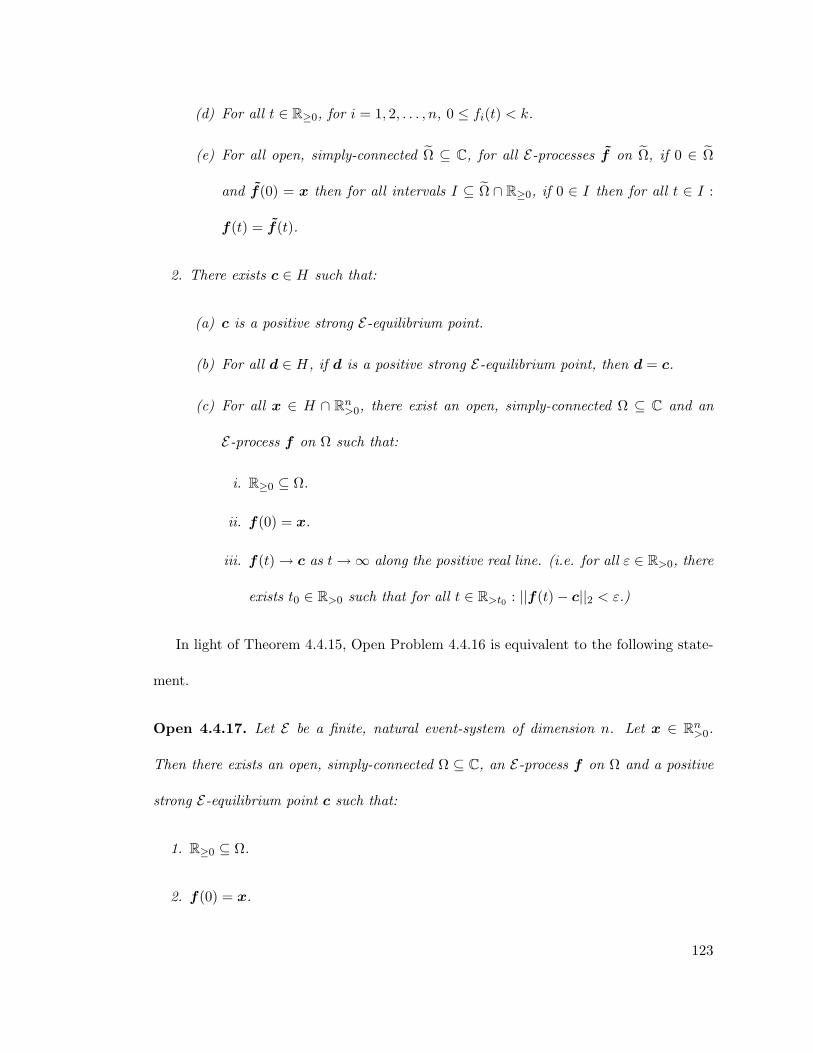
(d) For all t ∈ R≥0, for i = 1, 2, . . . , n, 0 ≤ fi(t) < k.
(e) For all open, simply-connected Ω ⊆ C, for all E-processes f on Ω, if 0 ∈ Ω
and f(0) = x then for all intervals I ⊆ Ω ∩ R≥0, if 0 ∈ I then for all t ∈ I :
f(t) = f(t).
2. There exists c ∈ H such that:
(a) c is a positive strong E-equilibrium point.
(b) For all d ∈ H, if d is a positive strong E-equilibrium point, then d = c.
(c) For all x ∈ H ∩ Rn>0, there exist an open, simply-connected Ω ⊆ C and an
E-process f on Ω such that:
i. R≥0 ⊆ Ω.
ii. f(0) = x.
iii. f(t)→ c as t→∞ along the positive real line. (i.e. for all ε ∈ R>0, there
exists t0 ∈ R>0 such that for all t ∈ R>t0 : ||f(t)− c||2 < ε.)
In light of Theorem 4.4.15, Open Problem 4.4.16 is equivalent to the following state-
ment.
Open 4.4.17. Let E be a finite, natural event-system of dimension n. Let x ∈ Rn>0.
Then there exists an open, simply-connected Ω ⊆ C, an E-process f on Ω and a positive
strong E-equilibrium point c such that:
1. R≥0 ⊆ Ω.
2. f(0) = x.
123

3. f(t) → c as t → ∞ along the positive real line. (i.e. for all ε ∈ R>0, there exists
t0 ∈ R>0 such that for all t ∈ R>t0 : ||f(t)− c||2 < ε.)
4.5 Finite Natural Atomic Event-Systems
In this section, we settle Open 4.4.16 in the affirmative for the case of finite, natural,
atomic event-systems. The atomic hypothesis appears to be a natural assumption to
make concerning systems of chemical reactions. Therefore, our result may be considered
a validation of the notion in chemistry that concentrations tend to equilibrium. We will
prove the following theorem:
Theorem 4.5.1. Let E be a finite, natural, atomic event-system of dimension n. Let
α ∈ Rn>0. Then there exists an open, simply-connected Ω ⊆ C, an E-process f on Ω, and
a positive strong E-equilibrium point c such that:
1. R≥0 ⊆ Ω,
2. f(0) = α, and
3. f(t) → c as t → ∞ along the positive real line (i.e. for all ε ∈ R>0, there exists
t0 ∈ R>0 such that for all t ∈ R>t0 : ‖f(t)− c‖2 < ε).
It follows from Theorem 4.4.15 that the point c depends only on the conservation
class of α and not on α itself. That is, two E-processes starting at positive points in the
same conservation class asymptotically converge to the same c.
Implicit in the atomic hypothesis is the idea that atoms are neither created nor de-
stroyed, but rather are conserved by chemical reactions. Our proof uses a formal analogue
124

of this idea. Recall from Definition 4.1.11 that if E is atomic then CE(M) contains a unique
monomial from MAE .
Definition 4.5.1. Let E be a finite, natural, atomic event-system of dimension n. The
atomic decomposition mapDE : MX1,X2,...,Xn → Zn≥0 is the function M 7→ 〈b1, b2, . . . , bn〉
such that Xb11 X
b22 · · ·Xbn
n ∈ CE(M) ∩MAE .
The next lemma lists some properties of the atomic decomposition map. Note that
though the event-graph GE is directed, if M and N are monomials and there exists a
path in GE from M to N then there also exists a path in GE from N to M . Informally,
this is because all events are “reversible”.
Lemma 4.5.2. Let E be a finite, natural, atomic event-system of dimension n and let
M,N ∈MX1,X2,...,Xn. Then:
1. DE(M) = DE(N) if and only if CE(M) = CE(N).
2. DE(MN) = DE(M) +DE(N).
Proof. Let D = DE .
(1) D(M) = D(N) = 〈b1, b2, . . . , bn〉 if and only if Xb11 X
b22 · · ·Xbn
n ∈ CE(M) and
Xb11 X
b22 · · ·Xbn
n ∈ CE(N). Then CE(M) = CE(N).
(2) Let D(M) = 〈b1, b2, . . . , bn〉 and D(N) = 〈c1, c2, . . . , cn〉. Then, in GE there is a
path from M to Xb11 X
b22 · · ·Xbn
n ∈ MAE and a path from N to Xc11 X
c22 · · ·Xcn
n ∈ MAE .
It follows that there is a path from MN to Xb1+c11 Xb2+c2
2 · · ·Xbn+cnn ∈ MAE . Hence
D(MN) = 〈b1 + c1, b2 + c2, . . . , bn + cn〉 = D(M) +D(N).
125

Definition 4.5.2. Let E be a finite, natural, atomic event-system of dimension n. For
all i ∈ 1, 2, . . . , n, for all M ∈MX1,X2,...,Xn, DE,i(M) is the ith component of DE(M).
Definition 4.5.3. Let E be a finite, natural, atomic event-system of dimension n. For
all i ∈ 1, 2, . . . , n the function κE,i : Cn → C is given by
〈z1, z2, . . . , zn〉 7−→n∑j=1
DE,i(Xj)zj .
Lemma 4.5.3. Let E be a finite, natural, atomic event-system of dimension n. Then for
all i ∈ 1, 2, . . . , n, the function κE,i is a conservation law of E.
Proof. Let m = |E|, and for j = 1, 2, . . . ,m, let σj , τj ∈ R>0 and Mj , Nj ∈ M∞ with
Mj ≺ Nj be such that E = σ1M1 − τ1N1, . . . , σmMm − τmNm. For i = 1, 2, . . . , n, let
aj,i, bj,i ∈ Z>0 be such that Mj = Xaj,11 X
aj,22 · · ·Xaj,n
n and Nj = Xbj,11 X
bj,22 · · ·Xbj,n
n . Let
(γj,i)m×n = ΓE .
Then for j = 1, 2, . . . ,m:
126

σjMj − τjNj ∈ E
⇒ Mj ∈ CE(Nj) [Definition 4.1.9]
⇒ DE(Mj) = DE(Nj) [Lemma 4.5.2]
⇒n∑i=1
aj,iDE(Xi) =n∑i=1
bj,iDE(Xi) [Lemma 4.5.2]
⇒n∑i=1
(bj,i − aj,i)DE(Xi) = 0
⇒n∑i=1
γj,iDE(Xi) = 0 [Definition 4.2.1]
It follows that for all j ∈ 1, 2, . . . ,m, for all k ∈ 1, 2, . . . , n,
n∑i=1
γj,iDE,k(Xi) = 0
Therefore, for all k ∈ 1, 2, . . . , n, ΓE · 〈DE,k(X1), DE,k(X2), . . . , DE,k(Xn)〉T = 0.
Since the vector 〈DE,k(X1), DE,k(X2), . . . , DE,k(Xn)〉T is in the kernel of ΓE , by Theo-
rem 4.2.2, κE,k is a conservation law of E .
Lemma 4.5.4. Let E be a finite, natural event-system of dimension n. Let M,N ∈M∞
and let q ∈ Cn. If M ∈ CE(N) and q is a strong E-equilibrium point and M(q) = 0, then
N(q) = 0.
Proof. Let 〈v0, v1〉 be an edge in GE . Then there exist e ∈ E and σ, τ ∈ R>0 and
T,U, V ∈M∞ such that e = σU − τV and v0 = TU and v1 = TV .
127

Assume v0(q) = 0. Then either T (q) = 0 or U(q) = 0. If T (q) = 0 then v1(q) = 0.
If U(q) = 0 and q is a strong E-equilibrium point, then e(q) = σU(q) − τV (q) = 0, so
V (q) = 0. Therefore v1(q) = 0. The lemma follows by induction.
We are now ready to prove Theorem 4.5.1.
Proof of Theorem 4.5.1. Since α is a positive point, it is in some positive conservation
class H. By Theorem 4.4.15:
1. There exists exactly one positive strong E-equilibrium point c ∈ H.
2. There exist an open and simply-connected Ω ⊆ C and an E-process f on Ω such
that R≥0 ⊂ Ω and f(0) = α.
3. For all t ∈ R≥0, f(t) ∈ H ∩ Rn≥0.
4. There exists k ∈ R≥0 such that for i = 1, 2, . . . , n, for all t ∈ R≥0, fi(t) ∈ R and
0 ≤ fi(t) ≤ k.
Let tjj∈Z>0 be an infinite sequence of non-negative reals such that tj → ∞ as
j →∞. Then f(tj)j∈Z>0 is an infinite sequence contained in a compact subset of Rn,
so it must have a convergent subsequence. Let q = 〈q1, q2, . . . , qn〉 ∈ Cn be the limit
point of a convergent subsequence of f(tj)j∈Z>0 . H and Rn≥0 are both closed in Cn, so
q ∈ H∩Rn≥0. Since E is natural and q is an ω-limit of f , q must be a strong E-equilibrium
point by Lemma 4.4.14.
Assume, for the sake of contradiction, that q /∈ Rn>0. Let i ∈ 1, 2, . . . , n be such that
qi = 0. Let N ∈ CE(Xi)∩MAE . Since E is atomic, a unique such N exists. It follows from
128

the definition of event graph that Xi ∈ CE(N). By Lemma 4.5.4, N(q) = Xi(q) = qi = 0.
It follows thatN 6= 1. Hence, there existsXa ∈ AE such thatXa dividesN andXa(q) = 0.
For all j ∈ 1, 2, . . . , n such that DE,a(Xj) 6= 0, let Mj ∈ CE(Xj) ∩MAE . Then Xa
divides Mj , so Mj(q) = 0. Again by Lemma 4.5.4, Xj(q) = Mj(q) = 0, so qj = 0. It
follows that for all j ∈ 1, 2, . . . , n either DE,a(Xj) = 0 or qj = 0 so
κE,a(q) =n∑j=1
DE,a(Xj)qj = 0.
Since κE,a is a conservation law of E by Lemma 4.5.3 and q is an ω-limit point of f , it
follows that
κE,a(α) = 0. (4.39)
For all j, DE,a(Xj) is nonnegative, and α is a positive point, so for all j ∈ 1, 2, . . . , n,
DE,a(Xj)αj ≥ 0. But DE,a(Xa) = 1 and αa > 0 so κE,a(α) > 0, contradicting equa-
tion (4.39). Therefore q ∈ Rn>0. Since c is the unique positive strong E-equilibrium point
in H, c = q.
Let U ⊆ H ∩ Rn>0 be the open set stated to exist in Theorem 4.4.15.2c. Since c is an
ω-limit point of f , there exists t0 ∈ R>0 such that f(t0) ∈ U . Again by Theorem 4.4.15,
there exist Ω ⊆ C and an E-process f on Ω such that R≥0 ⊆ Ω and f(0) = f(t0) and
f(t) → c as t → ∞. By Lemma 4.3.3, for all t ∈ R≥0, f(t + t0) = f(t). Therefore,
f(t)→ c as t→∞.
129

Chapter 5
Zeta Event-Systems
The mathematician Leopold Kronecker once said that “God created the integers, all else
is the work of man.” Is it possible to give formal meaning to the idea that the integers
were created from more primitive things? If so, that might give insight into why they
are as we see them now. In this chapter, we will describe how event-systems provide the
means to view the integers as the outcome of a self-assembly process. The work presented
in this chapter is the result of collaboration between Leonard Adleman and myself, and
the first person plural pronouns in this chapter refer to those authors.
In event-systems, we usually think of the reacting species as chemical compounds.
The systems themselves, however, have no intrinsic ties to chemistry. It is possible to
think of the reactants as other objects, such as physical objects being self-assembled or
even as pure numbers.
In chemistry, the atomic hypothesis states that all substances are composed of a
unique set of atoms. Atomic event-systems capture this idea: every reactant in an atomic
event-system is made up of a unique set of atoms. The atomic hypothesis in chemistry is
analogous to the fundamental theorem of arithmetic in mathematics: all natural numbers
130

are composed of a unique set of primes. One can imagine assembling the natural numbers
from the prime numbers by multiplication.
In this chapter, we will define a class of event-systems called zeta event-systems. We
will use event-systems to model the mathematical operation of multiplication. Intuitively,
these event-systems model chemical systems in which the reactants are natural numbers.
The numbers can react with one another to form their product.
Applying the law of mass action to an event-system (see Chapter 4) gives a set of
differential equations that tracks the time evolution of the concentration of each species.
If the species are identified with natural numbers, the reactions are identified with the
multiplication operator, and in the beginning the only species present are prime numbers,
then we can “watch” the natural numbers being created through time as primes combine
through multiplication.
Thermodynamic properties such as pressure and temperature have meaning in event-
systems, even if a particular system does not model chemical reactions. Pressure in event-
systems can be defined as the sum of the concentrations of all species. Temperature factors
into the specific rates: Other things being equal, at temperature T the specific rates are
proportional to e−1/T . In the zeta event-systems defined in this chapter, the reactions
and reaction rates are chosen carefully so that the system has a strong equilibrium point.
This equilibrium point is special in that, if the event-system is at temperature s, the
pressure at equilibrium is ζ(s), where ζ is the Riemann zeta function. Formal definitions
and proofs will be presented in Section 5.3.
131

The motivation for doing this is to increase our understanding of the Riemann zeta
function. By using event-systems and their associated event-processes, we add a dimen-
sion to the zeta function: time. The hope is that we can watch the numbers self-assemble
through time to create the zeta function, and that this self-assembly process can shed
light on the zeta function itself. In particular, the locations of the zeros of the Riemann
zeta function are extremely important in mathematics. Starting from initial conditions
that have no zeros anywhere in the complex plane, we may be able to “watch” the system
evolve and see how zeros arise. This may lead to insight on their final destinations, ideally
on the line with real part 12 .
5.1 Riemann Zeta Function
Countless books, both technical and popular, have been written about the Riemann zeta
function. This function has a fascinating history and is immensely important in mathe-
matics. Here we will only give a brief outline of its history, properties, and importance.
The Riemann zeta function ζ : C→ C is defined for Re(s) > 1 by
ζ(s) =∞∑n=1
1ns. (5.1)
When s = 1, the sum becomes the harmonic series, which diverges, as proved by
Nicole d’Orseme in the fourteenth century. When s = 2, the sum becomes the Basel
series, which Leonhard Euler proved converges to π2/6 in 1735 [21].
132

The Riemann zeta function can be analytically continued to the entire complex plane
(with a simple pole at s = 1) by
ζ(s) =1
1− 21−s
∞∑n=0
12n+1
n∑k=0
(−1)k(n
k
)(k + 1)−s. (5.2)
Euler also proved a deep connection between the Riemann zeta function and the prime
numbers [28]. For all s ∈ R>1,
ζ(s) =∞∑n=1
1ns
=∏
p prime
(1− p−s)−1 (5.3)
It is this connection for which the Riemann zeta function is best-known and most-studied.
Carl Friedrich Gauss (in 1793) and Adrien-Marie Legendre [54] (in 1796) indepen-
dently conjectured that the prime numbers are distributed in a certain way, though
Gauss’s work was not published until 1863 [33]. In its simplest form, the conjecture says
that
limn→∞
π(n)n/ ln(n)
= 1. (5.4)
133

where π(n) is the number of primes less than or equal to n. This can be stated more
succinctly as π(n) ∼ n/ ln(n). This conjecture became known as the Prime Number
Theorem. Gauss later improved the estimate to
π(n) ∼ Li(n) where Li(n) =∫ n
2
1ln(x)
dx. (5.5)
In 1859 Berhnard Riemann presented a paper titled “On the Number of Primes Less
Than a Given Quantity” [69]. As the title indicates, his paper was on the distribution
of primes. It was in this paper that Riemann generalized Euler’s result to the complex
numbers and laid out a plan to prove the conjecture of Gauss and Legendre. The function
defined in Equations (5.1) and (5.2) bears Riemann’s name because of the results in this
paper. It was also in this paper that he stated the Riemann Hypothesis: all the non-trivial
zeros of the Riemann zeta function lie on the line Re(s) = 12 .
In 1896 the Prime Number Theorem was proved independently by Jacques Hadamard
and Charles de la Vallee Poussin [40, 20], which established the correctness of the con-
jecture of Gauss and Legendre. Hadamard and Vallee Poissin did not prove the Riemann
Hypotheses; instead they proved the weaker result that there are no zeros of the Riemann
zeta function with Re(s) ≥ 1. To date, no one has proved the Riemann Hypothesis and
it is considered one of the greatest open questions in mathematics. Proving the Riemann
Hypothesis would strengthen the Prime Number Theorem by tightening the bounds on
the error function: how much π(n) and Li(n) differ.
134

In 1900 David Hilbert posed a list of 23 open problems at the Paris conference of the
International Congress of Mathematicians. Many of these problems turned out to be very
influential during the 20th century. Among the problems was the Riemann Hypothesis.
In 2000 the Clay Institute posed a list of seven open problems. They offer a one
million dollar prize for a solution to each of the problems. Again, among the problems is
the Riemann Hypothesis.
5.2 Basic Definitions and Notation
The event-systems in this chapter differ in several important ways from the event-systems
in Chapter 4. First, all zeta event-systems presented here are both infinite and infinite-
dimensional. This means that many of the definitions and theorems from Chapter 4
do not apply. Although it is often easy to extend the definitions and theorems from
Chapter 4 to the infinite case, great care must be taken not to introduce subtle problems.
As the goal of this chapter is not to give a complete description of what is known about
infinite event-systems, but to prove the existence and properties of zeta event-systems,
we will only formally extend the definitions and theorems needed for the task at hand.
Second, each zeta event-system is not an individual event-system, but a class of event-
systems that depend on a parameter, the system’s temperature. However, every complex
number can be used as the temperature parameter and the resulting system does turn
out to be an event-system (see Definition 5.2.2).
Third, the quantity of interest in this chapter is a measurement of the state of the
system. Most simply, this will be the pressure of the system (the sum of the concentrations
135

of all of the species). However, in some zeta event-systems, at some temperatures, at some
times, this infinite sum diverges. Later in this chapter, we will extend the definition of
pressure to mitigate this problem.
Finally, using Definition 4.2.3 for event-process leads to systems of infinitely many,
nonlinear, complex-valued, differential equations. These systems of differential equations
are difficult to analyze. We will approach this difficulty in two ways: we will define
“simplified event-processes” that keeps many of the features of the usual event-processes
but are more amenable to analysis, and we will use numerical methods to simulate the
event-processes of subsets of zeta event-systems.
The goal of this chapter is to present a class of event-systems with the property that
the pressure at equilibrium is the Riemann zeta function of the system’s temperature.
How the “pressure” of an event-system is measured and how the “temperature” of an
event-system affects it will be defined more formally in Sections 5.2.1 and 5.2.2, respec-
tively. Informally, however, in this chapter we will present event-systems in which species
Xn has, as its unique strong equilibrium value, n−s, where s is the temperature of the
system. By considering the pressure of the system (sum of the concentrations of all of
the species) at this equilibrium, we recover Equation (5.1), which defines the Reimann
zeta function on a half-plane.
To begin we will need notation to represent an infinite-dimensional event-system pa-
rameterized by temperature. Recall from Notation 4.1.1 that
C∞ =∞⋃n=1
C[X1, X2, · · · , Xn],
136

a monic monomial is a product of the form∏∞i=1X
eii where the ei are non-negative integers
all but finitely many of which are zero, and M∞ is the set of all monic monomials of C∞.
A holomorphic function f : C → C is zero-free iff for all x ∈ C, f(x) 6= 0. Let
F = f : C → C | f is holomorphic and zero-free. It is well-known that F = ef | f is
holomorphic. The set of parameterized binomials is Bp,∞ = σM + τN | σ, τ ∈ F and
M,N are distinct elements of M∞ and M ≺ N.
Definition 5.2.1. A parameterized event-system E is a nonempty, countable subset of
Bp,∞.
Given a parameterized event-system E , it is possible to evaluate the reaction rates at
s ∈ C resulting in a (nonparameterized) event-system E(s).
Definition 5.2.2. Let E be a parameterized event-system and let s ∈ C. Then E(s), or
E evaluated at s, is the event-system σ(s)M + τ(s)N | σ, τ ∈ F and M,N ∈ M∞ and
σM + τN ∈ E.
That E(s) is an event-system follows immediately from the the facts that σ and τ are
holomorphic (hence defined at s) and zero-free (hence nonzero at s).
Event-systems, in general, can be infinite-dimensional. However, Definition 4.1.6 only
defines points as finite-dimensional complex vectors. The following extends the defini-
tion to the countably infinite case, keeping the convention from Chapter 4 that points
are written in a bold symbol and the individual components that make up a point are
subscripted, normal-weight versions of that symbol:
Definition 5.2.3. Let CZ>0 be the set of all functions α : Z>0 → C. Then α ∈ CZ>0 is
a point in CZ>0 and for all n ∈ Z>0, αn = α(n).
137

Given a finite-dimensional event-system E of dimension n, one can evaluate an event
e ∈ E a point α ∈ Cn to get a value e(α) ∈ C. In infinite-dimensional event-systems, an
analogous result holds: Given an infinite-dimensional event-system E , one can evaluate
an event e ∈ E at a point α ∈ CZ>0 to get a value e(α) ∈ C. Recall that even though
E is infinite-dimensional, each event in E is a binomial, each term of which is a nonzero
complex number times a monic monomial in M∞, which can have only finitely many
factors.
If E is a finite-dimensional event-system of dimension n, a point α ∈ Cn may be a
strong equilibrium point of E by Definition 4.1.7. This definition has a straight-forward
extension to infinite-dimensional event-systems.
Definition 5.2.4. Let E be an infinite-dimensional event-system. A point α ∈ CZ>0 is a
strong equilibrium of E iff for all e ∈ E , e(α) = 0.
5.2.1 Pressure
The simplest definition of pressure in an event-system is simply the sum of the concen-
trations of each of the species. Let α ∈ CZ>0 , then
pres(α) =∞∑n=1
αn (5.6)
Note that at some concentrations α, pres(α) can diverge.
If s ∈ C is such that Re(s) > 1 and for all n ∈ Z≥1, αn = n−s, then pres(α) =∑∞n=1 n
−s = ζ(s) by Equation (5.1), which can be analytically continued to the entire
138

complex plane using Equation (5.2). Strictly by analogy, for all s ∈ C, we will define the
“continuation” of pressure to be
pres(α) =1
1− 21−s
∞∑n=0
12n+1
n∑k=0
(−1)k(n
k
)αk+1. (5.7)
5.2.2 Temperature
In chemistry, the specific rates of a reaction depend on the temperature at which the
reaction takes place. The Arrhenius equation describes how the specific rates vary with
the temperature. In the zeta event-systems in this chapter, the specific rates will be given
by the Arrhenius equation. The Arrhenius equation is usually given in the form
σ(T ) = Aσe−Ea,σ/RT and
τ(T ) = Aτe−Ea,τ/RT , (5.8)
where R is the universal gas constant, Aσ and Aτ are constants called the prefactors
of the reaction, and Ea,σ and Ea,τ are constants called the activation energies of the
reaction. Usually Aσ, Aτ , Ea,σ and Ea,τ are determined empirically for each reaction. For
convenience, rather than use the actual temperature T , the parameter s in zeta event-
systems will be the inverse of the temperature T :
s =1T. (5.9)
139

Zeta event-systems were created to model an abstract idea: multiplication. As such,
there is no experimental set-up in which the constants in the Arrhenius equation can be
empirically measured, and we are free to choose them however we wish. In creating zeta
event-systems, we will use two methods for choosing the constants. These are the same
two methods for both the forward rate σ and the backward rate τ , so in what follows,
A = Aσ and Ea = Ea,σ or A = Aτ and Ea = Ea,τ . The first method of choosing the
constants is
A = 1 and
Ea = 0. (5.10)
Using these constants in the Arrhenius equation, it is easy to verify that the specific rate
is the constant 1 at all complex temperatures T and all inverse temperatures s.
The other method we will use to choose the constants in the Arrhenius equation will
depend on the event: specifically the event’s number in some well-defined ordering of the
events. Let n ∈ Z>0 be the event’s number and let R be the universal gas constant. The
second method of choosing the constants is
A = 1 and
Ea =−R
ln(n)where ln(n) is taken to be real. (5.11)
Using these constants in the Arrhenius equation, it is easy to verify that, at temperature
T = 1/s, the specific rate is n−1/T = n−s.
140

Note that in both methods, the specific rates are analytic and zero-free in s = 1/T
(but not in T itself, which is one of the reasons for using s as the parameter rather than T ).
In the zeta event-systems in this chapter, all specific rates will come from the Arrhenius
equation with the prefactor and activation energy given in Equation (5.10) or (5.11), but
both methods may be combined in a single event (i.e., σ(s) given by Equation (5.10)
and τ(s) given by Equation (5.11)). Hence, all zeta event-systems are parameterized
event-systems.
5.2.3 Processes
The stoichiometric matrix is only defined for finite event-systems (Definition 4.2.1), but
it is possible to compute each entry of the stoichiometric matrix in infinite and infinite-
dimensional event-systems:
Definition 5.2.5. Let E = e1, e2, . . . be an infinite-dimensional event-system and let
i, j ∈ Z≥1. Let ej = σM + τN , where M,N ∈M∞ and M ≺ N . Then γj,i is the number
of times Xi divides N minus the number of times Xi divides M .
Similarly, the definition of event-process can be extended to infinite and infinite-
dimensional event-systems:
Definition 5.2.6 (Event-process). Let E = e1, e2, . . . be an infinite-dimensional event-
system and for all j ∈ Z≥1, let ej = σM + τN , where M,N ∈ M∞ and M ≺ N . For all
i ∈ Z≥1, let Pi =∑∞
k=1 γk,iek. Let Ω ⊆ C be a non-empty, simply-connected, open set.
For all i ∈ Z≥1, let fi : Ω → C. Then f = 〈f1, f2, . . .〉 is an E-process on Ω iff for all
i ∈ Z≥1:
141

1. f ′i exists on Ω and
2. f ′i = Pi f on Ω.
Such event-processes are difficult to work with analytically, so in Section 5.5 we will
use numerical methods to analyze them. For some infinite-dimensional event-systems,
however, it is possible to define a “simplified” event-process that is possible to analyze
analytically.
Definition 5.2.7 (Growth event-system). Let E be an event-system. E is a growth event-
system iff
1. for all e ∈ E , there exist j ∈ Z≥1, k ∈ Z≥0 such that k < j, i1, i2, . . . , ik ∈ Z≥0, and
σ, τ ∈ C \ 0 such that e = σXj + τ∏k`=1X
i`` and
2. for all j ∈ Z≥1, e = σXj + τN ∈ E | σ, τ ∈ C \ 0, N ∈M∞ is finite.
Note that in Definition 5.2.7, k is allowed to be 0, so events of the form σXj + τ
are allowed in growth event-systems. Intuitively, in growth event-systems every species
is composed only of smaller species, and only in a finite number of different ways.
Definition 5.2.8 (Simplified event-process). Let E be a growth event-system. For all
i, j ∈ Z≥1 let
γj,i =
−1 if there exist σ, τ ∈ C \ 0 and N ∈M∞ such that ej = σXi + τN
0 otherwise.
142

For all i ∈ Z≥1 let Pi =∑∞
j=1 γj,iej . Let Ω ⊆ C be a non-empty, simply-connected,
open set. For all i ∈ Z≥1 let fi : Ω → C. Then f = 〈f1, f2, . . .〉 is a simplified E-process
on Ω iff for all i ∈ Z≥1:
1. f ′i exists on Ω and
2. f ′i = Pi f on Ω.
5.3 Zeta Event-Systems
There are several different ways to formulate event-systems that have the Riemann zeta
function as the pressure of a strong equilibrium point. Below, we will define two different
zeta event-systems. The zeta event-systems below, as well as many other zeta event-
systems, share a common feature: the events are multiplicative. That is to say, all the
events have the form
Xn −k∏i=1
Xmi where n =k∏i=1
mi, or (5.12)
Xn − n−s. (5.13)
Intuitively, events of the form in Equation (5.13) “force” species Xn to have, as its
strong equilibrium value, n−s. Similarly, events of the form in Equation (5.12) force
species Xn to have, as its strong equilibrium value, the product the equilibrium values of
species Xm1 , Xm2 , . . . , Xmk . Taken together, this forces all species Xn to have, as their
strong equilibrium values, n−s.
143

In the first zeta event-system, Eζ,1, only pairwise multiplication of numbers is modeled,
and all pairwise multiplications of numbers greater than two are included. In chemistry,
reactions in which two reactants combine to form one product are called “bimolecular”
reactions, hence the name bimolecular zeta event-system.
Definition 5.3.1 (Bimolecular zeta event-system). For all s ∈ C, let Rs,1 = Xp − p−s |
p ∈ Z>1 and p is prime, let Cs,1 = Xnm−XnXm | n,m ∈ Z>1, and let Zs,1 = X1−1.
Then the zeta event-system Eζ,1 is the infinite-dimensional, parameterized event-system
Rs,1 ∪ Cs,1 ∪ Zs,1.
In Eζ,1 each species can be “built” from smaller species in many different ways. For
example, X12 −X2X6 and X12 −X3X4 are both events in Eζ,1 that build the number 12
from smaller numbers.
In the second zeta event-system, Eζ,2, there is only one event used to build each species
from smaller species: each species can only be built from its prime decomposition.
Definition 5.3.2 (Prime zeta event-system). Let s ∈ C. Let Zs,2 = X1 − 1. For all
p ∈ Z>1, let τp : C→ C be such that for all s ∈ C, τp(s) = p−s. Let Rs,2 = Xp− τp | p ∈
Z>1 prime. Let Cs,2 = Xn −Xp1Xp2 · · ·Xpk | n ∈ Z>1 is composite and p1p2 · · · pk is
the prime factorization of n. Then the zeta event-system Eζ,2 is the infinite-dimensional,
parameterized event-system Rs,2 ∪ Cs,2 ∪ Zs,2.
The following theorem states that zeta event-systems deserve that name: they have
a strong equilibrium point at which the pressure is the Riemann zeta function of the
temperature.
Theorem 5.3.1. For all s ∈ C, the point c = 〈1−s, 2−s, . . . , n−s, . . .〉 is such that
144

1. c is a strong Eζ,1(s)-equilibrium
2. c is a strong Eζ,2(s)-equilibrium
3. if Re(s) > 1 then pres(c) = ζ(s)
4. pres(c) = ζ(s).
Proof. Parts 1 and 2 follow immediately from the definitions of Eζ,1(s) and Eζ,2(s) and
from the fact that for all s ∈ C, for all n,m ∈ Z≥1, n−sm−s = (nm)−s. Parts 3 and 4
follow from Equations (5.1) and (5.2), respectively.
At temperature s, the pressure at a strong Eζ,1-equilibrium or a strong Eζ,2-equilibrium
is the Riemann zeta function’s value at s. But what about the dynamics? Starting from
all-zero initial conditions, does the event-process or simplified event-process asymptoti-
cally approach this equilibrium in forward real time?
Using Definition 5.2.6 of event-processes, this question turns out to be difficult to
answer analytically. In Section 5.5 we will give evidence that, at some temperatures, the
event-process does appear to approach the strong equilibrium, while at other tempera-
tures, the event-process appears chaotic.
However, using Definition 5.2.8 of simplified event-processes makes this question more
amenable to analysis. It turns out that both Eζ,1 and Eζ,2 have similar dynamics for both
the event-processes and simplified event-processes. For the rest of this section, we will
analyze only Eζ,2 but a similar analysis works for Eζ,1 to produce similar results.
Theorem 5.3.2. For all s ∈ C, for all i ∈ Z≥1 there exist fs,i : C → C such that
f s = 〈fs,1, fs,2, . . . 〉 is a simplified Eζ,2(s)-process on C and f s(0) = 〈1, 0, 0, . . . 〉. Further,
145

if Re(s) > 1 then pres(f s(t)) → ζ(s) as t → ∞ in the positive real direction and for all
s ∈ C, pres(f s(t))→ ζ(s) as t→∞ in the positive real direction.
Proof. Let s ∈ C and let E = Eζ,2(s). For all e ∈ E , there exist n, k ∈ Z≥1 and primes
p1, p2, . . . , pk ∈ Z≥1 such that
1. e = Xn − 1 (if n = 1) or
2. e = Xn − n−s (if n is prime) or
3. e = Xn−Xp1Xp2 · · ·Xpk (if n is composite and p1p2 . . . pk is the prime factorization
of n).
Note that for all n ∈ Z≥0 there is exactly one event in E of the form σXn + τN , for
some σ, τ ∈ C and N ∈M∞. Therefore, by Definition 5.2.8, there is exactly one j ∈ Z≥0
such that γj,n is nonzero. Hence,
Pn =
1−Xn if n = 1
n−s −Xn if n is prime
Xp1Xp2 · · ·Xpk −Xn if n = p1p2 · · · pk is the prime factorization of n
We would like to find f s = f = 〈f1, f2, . . . 〉, where for all i ∈ Z≥1, fi : C → C, such
that for all i ∈ Z≥1, f ′i = Pi f on C. To do this, we note that Pi f gives the following
system of ordinary differential equations:
146

For all prime p, and for all composite n such that p1p2 · · · pk is the prime factorization
of n,
f ′1 = 1− f1 (5.14)
f ′p = p−s − fp (5.15)
f ′n = fp1fp2 · · · fpk − fn (5.16)
Equation (5.14) is a one-dimensional, first-order, linear, ordinary differential equation
whose trivial solution
f1(t) = 1 (5.17)
satisfies the initial condition f1(0) = 1.
Let p ∈ Z>1 be prime. Then Equation (5.15) is a one-dimensional, first-order, linear,
ordinary differential equation whose solution
fp(t) = p−s(1− e−t) (5.18)
satisfies the initial condition fp(0) = 0.
Let n ∈ Z>1 be composite, let k and p1, p2, . . . , pk ∈ Z≥1 be such that p1p2 · · · pk is
the prime factorization of n. Then Equation (5.16) is a multi-dimensional, first-order,
147

nonlinear, ordinary differential equation. However, in light of the solutions given in
Equation (5.18), it can be transformed into
f ′n = p−s1 (1− e−t)p−s2 (1− e−t) · · · p−sk (1− e−t)− fn
= n−s(1− e−t)k − fn
= n−sk∑i=0
(k
i
)(−e−t)i − fn
= n−sk∑i=0
(k
i
)(−1)ie−it − fn (5.19)
Now, Equation (5.19) is a one-dimensional, first-order, linear, ordinary differential
equation. Let
g(t) = n−sk∑i=0
(k
i
)(−1)ie−it (5.20)
Then f ′n(t) = g(t)−fn(t), or equivalently, f ′n(t)+fn(t) = g(t). This has the well-known
solution
fn(t) = e−t(∫ t
1eτg(τ)dτ + κ
)(5.21)
where κ is a constant of integration. Using the initial condition fn(0) = 0,
κ = −∫ 0
1eτg(τ)dτ
=∫ 1
0eτg(τ)dτ (5.22)
148

Then
fn(t) = e−t(∫ t
1eτg(τ)dτ +
∫ 1
0eτg(τ)dτ
)= e−t
(∫ t
0eτg(τ)dτ
)= e−t
(∫ t
0eτn−s
k∑i=0
(k
i
)(−1)ie−iτdτ
)
= n−se−tk∑i=0
(k
i
)(−1)i
∫ t
0eτe−iτdτ
= n−se−tk∑i=0
(k
i
)(−1)i
∫ t
0eτ(1−i)dτ
= n−se−t
((k
0
)∫ t
0eτdτ −
(k
1
)∫ t
01 dτ +
k∑i=2
(k
i
)(−1)i
∫ t
0eτ(1−i)dτ
)
= n−se−t
((et − 1)− kt+
k∑i=2
(k
i
)(−1)i
i− 1(1− et(1−i))
)
= n−se−t
((et − 1)− kt+
k∑i=2
(k
i
)(−1)i
i− 1−
k∑i=2
(k
i
)(−1)i
i−1 et(1−i)
)
Let Hk be the kth harmonic number. Then, using the identity∑k
i=2
(ki
) (−1)i
i−1 = k(Hk−1),
fn(t) = n−se−t
((et − 1)− kt+ k(Hk − 1)−
k∑i=2
(k
i
)(−1)i
i− 1et(1−i)
)
= n−s − n−s(e−t + e−tk(1 + t−Hk) +
k∑i=2
(k
i
)(−1)i
i− 1e−it
)
= n−s − n−se−t(
1 + k(1 + t−Hk)−k−1∑i=1
(k
i+ 1
)(−1)i
ie−it
)
149

As t → ∞ in the positive real direction, fn(t) → n−s. So if Re(s) > 1 then
pres(f(t))→∑∞
n=1 n−s = ζ(s) by Equation (5.1). For all s ∈ C,
pres(f(t)) =1
1− 21−s
∞∑n=0
12n+1
n∑k=0
(−1)k(n
k
)fk+1(t)
→ 11− 21−s
∞∑n=0
12n+1
n∑k=0
(−1)k(n
k
)(k + 1)−s
= ζ(s)
by Equation (5.2).
The above theorem suggest the following definition and corollary.
Definition 5.3.3. Let s ∈ C. For all n ∈ Z≥1, let fs,n : C→ C be such that for all t ∈ C
1. if n = 1 then fs,1(t) = 1
2. if n is prime then fs,n(t) = p−s(1− e−t)
3. if n is composite, k ∈ Z>1 and p1, p2, . . . , pk are such that p1p2 · · · pk is the prime
factorization of n, and Hk is the kth harmonic number, then
fs,n = n−s − n−se−t(
1 + k(1 + t−Hk)−k−1∑i=1
(k
i+ 1
)(−1)i
ie−it
)
Then f s = 〈fs,1, fs,2, . . .〉.
Corollary 5.3.3. For all s ∈ C, f s is a simplified Eζ,2-process.
Proof. Follows immediately from the proof of Theorem 5.3.2.
150

5.4 Visualizing Event-Processes
To get a better understanding of the Riemann zeta function and zeta event-systems, a
technique called “domain coloring” can be used to visualize complex-valued functions of
a complex variable [29]. In this technique, each point in the complex plane is assigned
a color. In the coloring scheme used in this chapter, hue represents the argument of
a complex number and intensity and brightness represent the magnitude of a complex
number (see Figure 5.1). Complex numbers that are close to zero are nearly white and
complex numbers with large magnitude are nearly black.
More formally, let HSB map [0, 1]3 to colors in the HSB color space (Hue, Saturation,
Brightness). Then for all s ∈ C, the color of s is given by
s 7→ HSB(
arg(s)/(2π),max( |s|+ 0.1, 1),max(0.9/(1 + e.5|s|−4 + .1), 1)).
Complex-valued functions of a complex variable can be visualized using this technique.
Given a function f : C → C, each point s ∈ C is depicted using the color given by
HSB(f(s)).
Figure 5.1a is a representation of the identity function f(s) = s, for s = −10− 10i to
s = 10 + 10i. Note the nearly white spot in the center of the figure, which represents the
single root (i.e., zero) of the identity function.
Figure 5.1b shows the Riemann zeta function ζ(s) for s = −20− 10i to s = 20 + 50i.
Note the nearly white region near the negative real axis. In this region, the value of the
Riemann zeta function is close to zero. Indeed, several of the trivial zeros of the zeta
function are in this region. There is also a vertical line of nearly white spots that have
151

-10 -5 0 5 10
-10
-5
0
5
10
(a) Coloring of the identity function, f(s) = s,for s = −10− 10i to z = 10 + 10i.
-20 -10 0 10 20
-10
0
10
20
30
40
50
(b) Coloring of the Riemann zeta function ζ(s)for s = −20− 10i to s = 20 + 50i.
Figure 5.1: Visualizing complex-valued functions of a complex variable using domaincoloring. The identity function is shown in (a) and the Riemann zeta function is shownin (b). Positive real numbers are shown in varying shades of red, negative real numbersin varying shades of cyan, etc.
real part one-half. These are nontrivial zeros of the Riemann zeta function. There is also
a nearly black spot located at 1 + 0i, indicating the simple pole of the zeta function.
It is possible to use this technique to visualize the simplified Eζ,2(s)-process f s as
defined in Definition 5.3.3. Figures 5.2a to 5.2h show f s(t) for s = −10−5i to s = 10+50i
and for various t.
At t = 0 (as shown in Figure 5.2a) the event-process f s is at its initial conditions:
for all s ∈ C, f s(0) = 〈1, 0, 0, . . .〉. There are color variations throughout the image and
152

-10 -5 0 5 10
0
10
20
30
40
50
(a) t = 0
-10 -5 0 5 10
0
10
20
30
40
50
(b) t = 1.23× 10⁻⁷
-10 -5 0 5 10
0
10
20
30
40
50
(c) t = 1.27× 10⁻⁴
-10 -5 0 5 10
0
10
20
30
40
50
(d) t = 7.31× 10⁻³
-10 -5 0 5 10
0
10
20
30
40
50
(e) t = 0.130
-10 -5 0 5 10
0
10
20
30
40
50
(f) t = 1.21
-10 -5 0 5 10
0
10
20
30
40
50
(g) t = 7.49
-10 -5 0 5 10
0
10
20
30
40
50
(h) t = 35.0
Figure 5.2: Images of the simplified Eζ,2(s)-process f s, for s = 10− 5i to s = 10 + 50i.
153

periodic poles at Re(s) = 1. These features arise from using Equation (5.7) to measure
pressure, specifically the factor of 11−21−s .
At t = 35 (as shown in Figure 5.2h) the event-process f s has nearly converged to the
Riemann zeta function, at least in the range of temperatures (s values) shown. Note the
similarity between Figure 5.2h and Figure 5.1b.
In analyzing Figure 5.2 (and similar figures later in this chapter), we will sometimes
refer to features “moving”. By this, we mean that there exist s1, s2 ∈ C and t1, t2 ∈ R≥0
such that a feature (value, zero, pole, etc.) at f s1(t1) is also at f s2(t2). This can usually
easily be seen in the figure as a particular color shifting position from one image to the
next.
In Figure 5.2b, a dark band can be seen on the left side of the image, indicating that
the magnitude of the pressure becomes large for temperatures with large negative real
part. To the right of the dark band is a periodic colored band, indicating a region of
moderate pressure, and to the right of that, a light-colored band. Careful examination of
this light-colored band reveals many zeros. In Figures 5.2c and 5.2d, these bands appear
to move to the right.
These images give evidence that, as time moves from t = 0 in the positive real direc-
tion, the zeros of pres(f s(t)) move in approximately the positive real direction, at least
initially. It appears that there are three distinct types of zeros:
1. Those that move to a complex number s with Re(s) > 0 such that ζ(s) = 0, i.e.,
they move to a non-trivial zero of the Riemann zeta function.
154

2. Those that move to a complex number s such that f s(0) is a pole. We call these
“annihilation zeros”.
3. Those that initially move in approximately the positive real direction, but eventually
move to the negative real axis, to a trivial zero of the Riemann zeta function.
5.5 Numerical Simulations of Event Processes
In Section 5.3, we showed that for all s ∈ C, the zeta event-systems Eζ,1(s) and Eζ,2(s) have
a strong equilibrium point c such that pres(c) = ζ(s), and that Eζ,2(s) has a simplified
event-process that asymptotically converges in forward real time to this strong equilibrium
point. What about the event-processes (as opposed to the simplified event-processes) of
these zeta event-systems?
Since finding an explicit solution to the differential equations given by event-processes
of zeta event-systems is difficult, we have simulated subsets Eζ,1 and Eζ,2 numerically.
Rather than use infinitely many species Xi, the event-systems are truncated at a finite
value k and contain only events in C[X1, X2, X3, . . . , Xk]. Transforming the event-system
this way makes it a finite event-system, but it is still not physical nor natural because of
the complex reaction rates. Therefore the results in Chapter 4 do not guarantee that the
process will approach an equilibrium, stay within a compact set, nor even exist. It appears
from the numerical simulations, however, that under many conditions the event-processes
do approach the desired equilibria.
We have simulated Eζ,1 and Eζ,2, (and other zeta event-systems) for various values of
s and k. Initially, the simulations were written in C++. The Runge-Kutta method (both
155

with and without adaptive stepsize control) and the Bulirsch-Stoer method were used
to integrate the differential equations, with the algorithms as described in [65]. Later
attempts were programmed in Mathematica, using its NDSolve method to numerically
integrate.
The results from one simulation of a ζ event-system are shown in Figure 5.3. In this
simulation, k = 50 and the region of temperature simulated was the same as in Figure 5.2:
s = −10− 5i to s = 10 + 50i.
At t = 0 (as shown in Figure 5.3a), one can see the initial conditions of the event-
process. Figure 5.3a is identical to Figure 5.2a, indicating that the event-process and the
simplified event-process begin have the same state at t = 0.
Figures 5.3b and 5.3c appear similar to Figures 5.2b and 5.2c, at least qualitatively.
The black band appears on the left side of the images, with a band of periodic color to
its right, and a band of nearly white to the right of that. These bands appear to move
to the right, just as they did in Figure 5.2.
However, beginning in Figure 5.3c and becoming more pronounced in subsequent
images, areas of gray color appear in the nearly black regions. The gray pixels repre-
sent temperatures s at which the numerical simulation became unstable and could not
continue.
Beginning in Figure 5.3c and becoming more pronounced in subsequent images, dis-
continuities in color in the critical strip can be seen. Areas where discontinuities appear
eventually become gray: the discontinuities are a early sign that the simulation is be-
coming unstable. The discontinuities and instabilities in the simulation indicate that the
event-process is chaotic at some temperatures.
156

In the regions where the discontinuities and instabilities do not appear (right side
of Figure 5.3h and some places in the critical strip), it appears the system converges to
the equilibrium given in Theorem 5.3.1, albeit more slowly than in the simplified event-
process.
5.6 Discussion
Explorations of zeta event-processes and simplified zeta event-processes have hinted at
tantalizing properties of zeta event-systems. Of particular interest, of course, is the
behavior of the zeros of the event-processes. Numerical studies of these systems show the
following recurring themes.
1. The zeros of zeta-processes move continuously as a function of time.
2. The zeros of zeta-processes begin (at time 0) at the point at (complex) infinity, and,
at least initially, move in the positive real direction through positive real time.
3. There are three types of zeros of zeta-processes:
(a) Those that eventually become trivial zeros of the Riemann zeta function (trivial
zeros).
(b) Those that eventually become nontrivial zeros of the Riemann zeta function
(nontrivial zeros).
(c) Those that eventually “annihilate” poles introduced by the factor of 11−21−s
that appears in pres (annihilation zeros).
157

One might suspect that the three types of zeros are independent of one another.
Perhaps surprisingly, this appears not to be the case. Numerical studies of simplified
zeta-processes suggest the three types of zeros are related through complex time. That is
to say, as t moves through C, a trivial zero may become a nontrivial zero or an annihilation
zero.
The pressure of the simplified Eζ,2-process can be viewed as a complex-valued function
of two complex variables, temperature s and time t. From numerical explorations, it
appears this function is a two-dimensional meromorphic function. Further, it appears
that the zero set of this function forms a one-dimensional complex manifold and can be
viewed as the Riemann surface of a complete analytic function. While the structure of the
branch points of this complete analytic function appears to be quite intricate, the function
may contain substantial information about the structure of the zeros of the Riemann zeta
function. In particular, the value on each branch as t approaches infinity in the positive
real direction appears to converge to the position of one of the trivial, nontrivial, or
annihilation zeros of the Riemann zeta function. Coming to understand this complete
analytic function could aid in the understanding of the Riemann zeta function.
158

(a) t = 0 (b) t = 6.38× 10⁻⁸ (c) t = 1.48× 10⁻² (d) t = 0.335
(e) t = 4.14 (f) t = 30.8 (g) t = 66.2 (h) t = 100
Figure 5.3: Images of the numerical simulation of a Eζ,2(s)-process, for s = 10 − 5i tos = 10 + 50i. Gray indicates temperatures and times where the numerical simulationbecame unstable and could not continue.
159

References
[1] H. Abelson, D. Allen, D. Coore, C. Hanson, G. Homsy, T. Knight, R. Nagpal,E. Rauch, G. Sussman, and R. Weiss. Amorphous computing. Communications ofthe ACM, 43:74–82, 2000.
[2] L. Adleman. Molecular computation of solutions to combinatorial problems. Science,266:1021–1024, 1994.
[3] L. Adleman. Towards a mathematical theory of self-assembly. Technical Report00-722, Department of Computer Science, University of Southern California, 2000.
[4] L. Adleman, Q. Cheng, A. Goel, and M. Huang. Running time and program sizefor self-assembled squares. In Proceedings of the ACM Symposium on Theory ofComputing (STOC), pages 740–748, 2001.
[5] L. Adleman, Q. Cheng, A. Goel, M. Huang, D. Kempe, P. Moisset, and P. Rothe-mund. Combinatorial optimization problems in self-assembly. In Proceedings of theACM Symposium on Theory of Computing (STOC), pages 23–32, 2002.
[6] L. Adleman, Q. Cheng, A. Goel, M. Huang, and H. Wasserman. Linear self-assemblies: equilibria, entropy, and convergence rates. In New Progress in DifferenceEquations. Taylor and Francis, London, 2003.
[7] L. Adleman, J. Kari, L. Kari, and D. Reishus. On the decidability of self-assembly ofinfinite ribbons. In Proceedings of the 43rd Symposium on Foundations of ComputerScience (FOCS02), pages 530–537, Washington, DC, USA, 2002. IEEE ComputerSociety.
[8] L. Adleman, J. Kari, L. Kari, D. Reishus, and P. Sosik. The undecidability of theinfinite ribbon problem: Implications for computing by self-assembly. SIAM Journalon Computing, 38(6):2356–2381, 2008.
[9] L. Ahlfors. Complex Analysis. International Series in Pure and Applied Mathemat-ics. McGraw-Hill, 1979.
[10] R. Barish, P. Rothemund, and E. Winfree. Two computational primitives for algo-rithmic self-assembly: Copying and counting. Nano Letters, 5(12):2586–2592, 2005.
[11] J. Bath, S. Green, and A. Turberfield. A free-running DNA motor powered by anicking enzyme. Angew. Chem. Int. Edn., 44:4358–4361, 2005.
160

[12] Y. Benenson, T. Paz-Elizur, R. Adar, E. Keinan, and Z. Livneh. Programmable andautonomous computing machines made of biomolecules. Nature, 414:430–434, 2001.
[13] R. Berger. The undecidability of the domino problem. Mem. Amer. Math. Soc,66:1–72, 1966.
[14] D. Bernstein and S. Bhat. Nonnegativity, reducibility, and semistability of massaction kinetics. In IEEE Conference on Decision and Control, pages 2206–2211.IEEE Publications, December 1999.
[15] Y. Brun, M. Gopalkrishnan, D. Reishus, B. Shaw, N. Chelyapov, and L. Adleman.Building blocks for DNA self-assembly. In Proceedings of the 1st Foundations ofNanoscience: Self-Assembled Architectures and Devices (FNANO04), pages 2–15,Snowbird, UT, USA, April 2004.
[16] N. Chelyapov, Y. Brun, M. Gopalkrishnan, D. Reishus, B. Shaw, and L. Adleman.DNA triangles and self-assembled hexagonal tilings. Journal of American ChemicalSociety (JACS), 126(43):13924–13925, October 2004.
[17] H. Chen, A. Goel, C. Luhrs, and E. Winfree. Self-assembling tile systems thatheal from small fragments. In Proceedings of 13th International Meeting on DNAComputing (DNA13), pages 30–46, 2007.
[18] J. Chen and N. Seeman. The synthesis from DNA of a molecule with the connectivityof a cube. Nature, 350:631–633, 1991.
[19] M. Cook, P. Rothemund, and E. Winfree. Self-assembled circuit patterns. In 9thInternational Workshop on DNA Based Computers (DNA9), pages 91–107, 2004.
[20] C. de la Vallee Poussin. Recherches analytiques la thorie des nombres premiers.Ann. Soc. scient. Bruxelles, 20:183–256, 1896.
[21] J. Derbyshire. Prime Obsession. Plume (The Penguin Group), 2003.
[22] B. Ding, R. Sha, and N. Seeman. Pseudohexagonal 2D DNA crystals from doublecrossover cohesion. Journal of the American Chemical Society, 126(33):10230–10231,2004.
[23] M. Dubois, B. Deme, T. Gulik-Krzywicki, J.C. Dedieu, C. Vautrin, S. Desert,E. Perex, and T. Zemb. Self-assembly of regular hollow icosahedra in salt-free catan-ionic solutions. Nature, 411:672–675, 2001.
[24] H. Ebbinghaus. Domino threads and complexity. In E. Borger, editor, ComputationTheory and Logic, volume 270 of Lecture Notes in Computer Science, pages 131–142.Springer, 1987.
[25] D. Eisenbud and B. Sturmfels. Binomial ideals. Duke Math. J., 84(1):1–45, 1996.
[26] Y. Etzion. On the solvability of domino snake problems. Master’s thesis, The Weiz-mann Institute of Science, Rehovot, Israel, 1991.
161

[27] Y. Etzion-Petruschka, D. Harel, and D. Myers. On the solvability of domino snakeproblems. Theoretical Computer Science, 131:243–269, 1994.
[28] L. Euler. Varia observationes circa series infinitas. St. Petersburg Academy, 1737.
[29] F. Farris. Review: Visual complex analysis. American Mathematical Monthly,105(6):570–576, 1997.
[30] M. Feinberg. The existence and uniqueness of steady states for a class of chemicalreaction networks. Arch. Rational Mech. Anal., 132:311–370, 1995.
[31] T. Fu and N. Seeman. DNA double-crossover molecules. Biochemistry, 32(13):3211–3220, 1993.
[32] K. Gatermann and B. Huber. A family of sparse polynomial systems arising inchemical reaction systems. Journal of Symbolic Computation, 33(3):275–305, 2002.
[33] C. Gauss. Werke, volume 10, page 10. K. Gesellschaft der Wissenschaften zuGottingen, 1863.
[34] A. Goel and P. Moisset. Towards minimum size self-assembled counters. In Proceed-ings of 13th International Meeting on DNA Computing (DNA13), pages 131–141,2007.
[35] M. Gomez-Lopez, J. Preece, J. Preece, and J. Stoddart. The art and science ofself-assembling molecular machines. Nanotechnology, 7(3):183–192, 1996.
[36] R. Goodman, I. Schaap, C. Tardin, C. Erben, R. Berry, C. Schmidt, and A. Turber-field. Rapid chiral assembly of rigid dna building blocks for molecular nanofabrica-tion. Science, 310(5754):1661–1665, 2005.
[37] D. Gracias, J. Tien, T. Breen, C. Hsu, and G. Whitesides. Forming electrical net-works in three dimensions by self-assembly. Science, 289:1170–1173, 2000.
[38] S. Green, L. Lubrich, and A. Turberfield. DNA hairpins: fuel for autonomous DNAdevices. J. Biophys, 91:2966–2975, 2006.
[39] C. Guldberg and P. Waage. Studies concerning affinity. Journal of chemical educa-tion, 63:1044, 1986.
[40] J. Hadamard. Sur la distribution des zeros do la fonction ζ(s) et ses consequencesarithmetiques. Bulletin of the Mathematical Society of France, 24:199–220, 1896.
[41] P. Hartman and W. Perdok. On the relations between crystal structure and mor-phology i. Acta Crystallographica, 8:49–52, 1955.
[42] D. Hilbert. Uber die stetige abbildung einer linie auf ein flachtenstuck. Math. Ann,38:459–460, 1891.
[43] M. Hirsch, S. Smale, and R. Devaney. Differential equations, dynamical systems,and an introduction to chaos. Elsevier Academic Press, Amsterdam, 2nd edition,2004.
162

[44] F. Horn. The dynamics of open reaction systems. In Mathematical aspects of chem-ical and biochemical problems and quantum chemistry, volume VIII of Proc. SIAM-AMS Sympos. Appl. Math., New York, 1974.
[45] F. Horn and R. Jackson. General mass action kinetics. Arch. Rational Mech. Anal.,49:81–116, 1972.
[46] M. Irwin. Smooth Dynamical Systems. Academic Press, 1980.
[47] K. Ito, editor. Encyclopedic Dictionary of Mathematics. MIT Press, Cambridge,Massachusetts, 1987.
[48] M. Kao and R. Schweller. Reducing tile complexity for self-assembly through tem-perature programming. In Proceedings of the ACM-SIAM Symposium on DiscreteAlgorithms (SODA), pages 571–580, 2006.
[49] J. Kari. Reversibility of 2D cellular automata is undecidable. Physica D, 45:379–385,1990.
[50] J. Kari. Reversibility and surjectivity problems of cellular automata. Journal ofComputer and System Sciences, 48(1):149–182, 1994.
[51] D. Konig. Uber eine schlussweise aus dem endlichen ins unendliche. Acta Litt. Sci,3:121–130, 1927.
[52] T. LaBean, H. Yan, J. Kopatsch, F. Liu, E. Winfree, J.. Reif, and N. Seeman. Con-struction, analysis, ligation, and self-assembly of DNA triple crossover complexes.Journal of the American Chemical Society, 122(9):1848–1860, 2000.
[53] M. Lagoudakis and T. LaBean. 2D DNA self-assembly for satisfiability. In Pro-ceedings of 5th Annual Meeting on DNA Based Computers (DNA5), pages 141–154,1999.
[54] A. Legendre. Essai sur la theorie des nombres. Duprat, 1798.
[55] T. Liedl and F. Simmel. Switching the conformation of a DNA molecule with achemical oscillator. Nano Letters, 5:1894–1898, 2005.
[56] D. Liu, S. Park, J. Reif, and T. LaBean. DNA nanotubes self-assembled from triple-crossover tiles as templates for conductive nanowires. Proceedings of the NationalAcademy of Science, 101:717–722, January 2004.
[57] D. Liu, M. Wang, Z. Deng, R. Walulu, and C. Mao. Tensegrity: Construction ofrigid DNA triangles with flexible four-arm DNA junctions. Journal of the AmericanChemical Society, 126(8):2324–2325, 2004.
[58] G. Lopinski, D. Wayner, and R. Wolkow. Self-directed growth of molecular nano-structures on silicon. Nature, 406:48–51, 2000.
[59] C. Mao, T. LaBean, J. Reif, and N. Seeman. Logical computation using algorithmicself-assembly of DNA triple-crossover molecules. Nature, 407:493–496, 2000.
163

[60] F. Mathieu, S. Liao, J. Kopatsch, T. Wang, C. Mao, and N. Seeman. Six-helixbundles designed from DNA. Nano Letters, 5(4):661–665, 2005.
[61] B. Muller, A. Reuter, F. Simmel, and D. Lamb. Single-pair FRET characterizationof DNA tweezers. Nano Letters, 6:2814–2820, 2006.
[62] S. Narayan and P. Mittal. A textbook of matrices. S. Chand and Company Ltd.,New Delhi, 10th edition, 2003.
[63] S. Park, R. Barish, H. Li, J. Reif, G. Finkelstein, H. Yan, and T. LaBean. Three-helixbundle DNA tiles self-assemble into 2D lattice or 1D templates for silver nanowires.Nano Letters, 5(4):693–696, 2005.
[64] R. Plass, J. Last, N. Bartelt, and G. Kellogg. Self-assembled domain patterns.Nature, 412:875, 2001.
[65] W. Press, S. Teukolsky, W. Vetterling, and B. Flannery. Numerical Recipes: TheArt of Scientific Computing. Cambridge University Press, third edition, 2007.
[66] J. Qi, X. Li, X. Yang, and N. Seeman. Ligation of triangles built from bulged 3-armDNA branched junctions. Journal of the American Chemical Society, 118(26):6121–6130, 1996.
[67] J. Reif. Local parallel biomolecular computation. In Proceedings of 3rd AnnualMeeting on DNA Based Computers (DNA3), pages 217–254, 1999.
[68] D. Reishus, B. Shaw, Y. Brun, N. Chelyapov, and L. Adleman. Self-assembly ofDNA double-double crossover complexes into high-density, doubly connected, planarstructures. Journal of American Chemical Society (JACS), 127(50):17590–17591,November 2005.
[69] B. Riemann. Ueber die anzahl der primzahlen unter einer gegebenen grosse. Monats-berichte der Berliner Akademie, 1859.
[70] R. Robinson. Undecidability and nonperiodicity for tilings of the plane. Inven.Math, 12:177–209, 1971.
[71] P. Rothemund. Using lateral capillary forces to compute by self-assembly. Proceed-ings of the National Academy of Sciences, 9:984–989, 2000.
[72] P. Rothemund. Folding dna to create nanoscale shapes and patterns. Nature,440:297–302, 2006.
[73] P. Rothemund, A. Ekani-Nkodo, N. Papadakis, A. Kumar, D. Fygenson, and E. Win-free. Design and characterization of programmable DNA nanotubes. Journal of theAmerican Chemical Society, 126(50):16344–16353, 2004.
[74] P. Rothemund, N. Papadakis, and E. Winfree. Algorithmic self-assembly of DNASierpinski triangles. PLoS Biology, 2(12):e424, 2004.
164

[75] P. Rothemund and E. Winfree. The program-size complexity of self-assembledsquares. In Proceedings of the ACM Symposium on Theory of Computing (STOC),pages 459–468, 2001.
[76] J. Schon, H. Meng, and Z. Bao. Self-assembled monolayer organic field-effect tran-sistors. Nature, 413:713–715, 2000.
[77] N. Seeman and N. Kallenbach. DNA branched junctions. Annual Review of Bio-physics and Biomolecular Structure, 23:53–86, 1994.
[78] W. Sherman and N. Seeman. A precisely controlled dna biped walking device. NanoLetters, 4:1203–1207, 2004.
[79] W. Shih, J. Quispe, and G. Joyce. A 1.7-kilobase single-stranded DNA that foldsinto a nanoscale octahedron. Nature, 427:618–621, 2004.
[80] D. Soloveichik and E. Winfree. Complexity of self-assembled shapes. SIAM Journalon Computing, 36(6):1544–1569, 2007.
[81] E. Sontag. Structure and stability of certain chemical networks and applications tothe kinetic proofreading model of T-cell receptor signal transduction. IEEE Trans.Automatic Control, 46:1028–1047, 2001.
[82] Y. Tian, Y. He, Y. Peng, and C. Mao. A DNA enzyme that walks processively andautonomously along a one-dimensional track. Angew. Chem. Int. Edn, 44:4355–4358,2005.
[83] H. Wang. Proving theorems by pattern recognition. BellSystems Technical Journal,40:1–42, 1961.
[84] G. Whitesides, J. Mathias, and C. Seto. Molecular self-assembly and nanochemistry:a chemical strategy for the synthesis of nanostructures. Science, 254:1312–1319,1991.
[85] E. Winfree. Algorithmic Self-Assembly of DNA. PhD thesis, California Institute ofTechnology, 1998.
[86] E. Winfree, F. Liu, L. Wenzler, and N. Seeman. Design and self-assembly of two-dimensional DNA crystals. Nature, 394:539–544, 1998.
[87] E. Winfree, X. Yang, and N. Seeman. Universal computation via self-assembly ofDNA: Some theory and experiments. DNA Based Computers II, pages 191–213,1998.
[88] Erik Winfree, Xiaoping Yang, and Nadrian C. Seeman. Universal computation viaself-assembly of dna: Some theory and experiments. In DNA Based Computers II,volume 44 of DIMACS, pages 191–213. American Mathematical Society, 1996.
[89] H. Yan, S. Park, G. Finkelstein, J. Reif, and T. LaBean. DNA-templated self-assembly of protein arrays and highly conductive nanowires. Science, 301:1882–1884,September 2003.
165

[90] X. Yang, L. Wenzler, J. Qi, X. Li, and N. Seeman. Ligation of DNA trianglescontaining double crossover molecules. Journal of the American Chemical Society,120(38):9779–9786, 1998.
[91] B. Yurke, A. Turberfield, Jr A. Mills, F. Simmel, and J. von Neumann. A DNA-fuelled molecular machine made of DNA. Nature, 406:605–608, 2000.
166