Omnicast Video Unit Configuration Guide 4.8 SR1
78
Omnicast Video Unit Configuration Guide 4.8 SR1 Click here for the most recent version of this document.
Transcript of Omnicast Video Unit Configuration Guide 4.8 SR1
OmnicastVideo Unit Configuration Guide
4.8 SR1
Click here for the most recent version of this document.

Copyright notice© 2011, 2012 Genetec Inc. All rights reserved.Genetec Inc. distributes this document with software that includes an end-user license agreement and is furnished under license and may be used only in accordance with the terms of the license agreement. The contents of this document are protected under copyright law.The contents of this guide are furnished for informational use only and are subject to change without notice. Genetec Inc. assumes no responsibility or liability for any errors or inaccuracies that may appear in the informational content contained in this guide.This publication may not be copied, modified, or reproduced in any form or for any purpose, nor can any derivative works be created therefrom without Genetec Inc.’s prior written consent. Genetec Inc. reserves the right to revise and improve its products as it sees fit. This document describes the state of a product at the time of document’s last revision, and may not reflect the product at all times in the future.In no event shall Genetec Inc. be liable to any person or entity with respect to any loss or damage that is incidental to or consequential upon the instructions found in this document or the computer software and hardware products described herein. The use of this document is subject to the disclaimer of liability found in the end–user license agreement."Genetec", "Omnicast", "Synergis", "AutoVu", "Federation", the Genetec stylized "G" and the Omnicast, Synergis and AutoVu logos are trademarks of Genetec Inc., either registered or pending registration in several jurisdictions."Security Center", "Security Center Mobile", "Plan Manager", and the Security Center logo are trademarks of Genetec Inc.Other trade names used in this document may be trademarks or registered trademarks of the manufacturers or vendors of the respective products.All specifications are subject to change without notice.
Document informationDocument title: Omnicast Video Unit Configuration Guide 4.8 SR1Document number: EN.100.007-V4.8.C1(2)Document update date: February 21, 2012You can send your comments, corrections, and suggestions about this guide to [email protected].
ii genetec.com | Omnicast 4.8 SR1 | Video Unit Configuration Guide | Download latest versionEN.100.007-V4.8.C1(2)

Product documentationOmnicast includes the following documentation:• Omnicast Release Notes. Describes the Omnicast release in detail, including new features, fixed issues,
and known issues.• Omnicast Installation and Upgrade Guide. Describes the prerequisites for installing Omnicast and pro-
vides instructions for installing and upgrading Omnicast on your system.• Omnicast Administrator Guide. Provides all the instructions and conceptual information you’ll need to
set up, configure, and administer your Omnicast system.• Omnicast Live Viewer User Guide. The Live Viewer is the control and monitoring center of your entire
security system. This manual teaches you how to perform your every day monitoring functions.• Omnicast Archive Player User Guide. The Archive Player is Omnicast’s investigative tool. This manual
explains how to perform intelligent archive database queries based on date, time, camera, event type, motion, complex metadata tags, bookmarks, and past alarms.
• Omnicast Video Unit Configuration Guide. Provides the pre-configuration instructions for integrating video units into Omnicast, and any configuration steps required for some video unit features to work.
• Omnicast Portable Archive Player User Guide. Explains how to use the Portable Archive Player to view exported video files.
Where can I find the product documentation?• Product DVD. The documentation is available on the product DVD in the Documentation folder. Release
notes and installation guides include a direct link to the latest version of the document.• Genetec Technical Assistance Portal (GTAP). The latest version of the documentation is available from
GTAP. Note, you’ll need a username and password to log on to GTAP.• Online help. Omnicast client applications include online help, which explain how the product works and
provide instructions on how to use the product features. To access the online help, click Help in the different client applications.
genetec.com | Omnicast 4.8 SR1 | Video Unit Configuration Guide| Download latest version iiiEN.100.007-V4.8.C1(2)

Technical supportGenetec Technical Assistance Center (GTAC) is committed to providing its worldwide clientele with the best technical support services available. As a Genetec customer, you have access to the Genetec Technical Assistance Portal (GTAP), where you can find information and search for answers to your product questions.• Genetec Technical Assistance Portal (GTAP). GTAP is a support website that provides in-depth support
information, such as FAQs, knowledge base articles, user guides, supported device lists, training videos, product tools, and much more.Prior to contacting GTAC or opening a support case, it is important to look at this website for potential fixes, workarounds, or known issues. You can log in to GTAP or sign up at https://gtap.genetec.com.
• Genetec Technical Assistance Center (GTAC). If you cannot find your answers on GTAP, you can open a support case online at https://gtap.genetec.com. For GTAC's contact information in your region see the Contact page at https://gtap.genetec.com.NOTE Before contacting GTAC, please have your System ID (available from the About button in your cli-ent application) and your SMA contract number (if applicable) ready.
• Licensing. For license activations or resets, please contact GTAC at https://gtap.genetec.com. For issues with license content or part numbers, or concerns about an order, please contact Genetec
Customer Service at [email protected], or call 1-866-684-8006 (option #3). If you require a demo license or have questions regarding pricing, please contact Genetec Sales at
[email protected], or call 1-866-684-8006 (option #2).
Additional resourcesIf you require additional resources other than the Genetec Technical Assistance Center, the following is available to you:• GTAP Forum. The Forum is an easy to use message board that allows clients and Genetec staff to com-
municate with each other and discuss a variety of topics, ranging from technical questions to technology tips. You can log in or sign up at https://gtapforum.genetec.com.
• Technical training. In a professional classroom environment or from the convenience of your own office, our qualified trainers can guide you through system design, installation, operation, and troubleshooting. Technical training services are offered for all products and for customers with a varied level of technical experience, and can be customized to meet your specific needs and objectives. For more information, go to http://www.genetec.com/English/Support/Training.
iv genetec.com | Omnicast 4.8 SR1 | Video Unit Configuration Guide | Download latest versionEN.100.007-V4.8.C1(2)

Contents
Product documentation . . . . . . . . . . . . . . . . . . iiiTechnical support . . . . . . . . . . . . . . . . . . . iv
About this guide . . . . . . . . . . . . . . . . . . . . ixWho should read this guide . . . . . . . . . . . . . . . ix
Chapter 1: Video unit configurationAll manufacturers . . . . . . . . . . . . . . . . . . . 2ACTi . . . . . . . . . . . . . . . . . . . . . . 3
Configuring network connection . . . . . . . . . . . . . . 3Select ACTi video streams . . . . . . . . . . . . . . . . 3Upgrading ACTi unit firmware. . . . . . . . . . . . . . . 3
Arecont . . . . . . . . . . . . . . . . . . . . . 4Configure Arecont cropped field of view . . . . . . . . . . . . 4Configuring Arecont camera image settings . . . . . . . . . . . 4
Configure picture settings . . . . . . . . . . . . . . . 5Configure illumination settings . . . . . . . . . . . . . . 5Configure exposure settings . . . . . . . . . . . . . . 6Configure day/night settings . . . . . . . . . . . . . . 7Configure flicker control . . . . . . . . . . . . . . . 8Configure camera orientation . . . . . . . . . . . . . . 9
Upgrading Arecont unit firmware . . . . . . . . . . . . . . 9Configuring Arecont H.264 units . . . . . . . . . . . . . . 9
ATEME . . . . . . . . . . . . . . . . . . . . . 10Configure VSIP-2 units. . . . . . . . . . . . . . . . . 10
Axis . . . . . . . . . . . . . . . . . . . . . . 11Configure Axis H.264 cameras . . . . . . . . . . . . . . . 11Configure recording schedules . . . . . . . . . . . . . . . 11Configure trickling for Axis units . . . . . . . . . . . . . . 12Configuring the Axis T8310 Video Surveillance Control Board . . . . . . . 15Configure multi-view areas . . . . . . . . . . . . . . . . 21
genetec.com | Omnicast 4.8 SR1 | Video Unit Configuration Guide | Download latest version vEN.100.007-V4.8.C1(2)

Creating PTZ patterns . . . . . . . . . . . . . . . . . 22Configure PTZ patterns . . . . . . . . . . . . . . . . 22Edit PTZ presets . . . . . . . . . . . . . . . . . 23
Basler . . . . . . . . . . . . . . . . . . . . . . 24Change the default port for input pin events . . . . . . . . . . . . 24Configuring Basler BIP2 units . . . . . . . . . . . . . . . 25
Reset the factory default settings . . . . . . . . . . . . . . 25Set the video stream encoder types . . . . . . . . . . . . . 26
Configure Basler BIP2-640c-dn units . . . . . . . . . . . . . 27Bosch . . . . . . . . . . . . . . . . . . . . . . 28
Configure video analytics . . . . . . . . . . . . . . . . 28Configuring Bosch H.264 units . . . . . . . . . . . . . . . 29
Enable software motion detection . . . . . . . . . . . . . 29Enable 60 frames per second . . . . . . . . . . . . . . 30
Configuring Bosch Divar 700 DVRs . . . . . . . . . . . . . . 31Configure Analog cameras . . . . . . . . . . . . . . . 31Configure network cameras . . . . . . . . . . . . . . . 31Configure recording settings . . . . . . . . . . . . . . 32
Configuring Bosch VRM units . . . . . . . . . . . . . . . 33Enable audio recording . . . . . . . . . . . . . . . . 34
Configure the Bosch Intuikey CCTV keyboard . . . . . . . . . . . 35Canon . . . . . . . . . . . . . . . . . . . . . . 38
Configuring Canon VB-C60 and VB-C500D units . . . . . . . . . . 38Grant user access . . . . . . . . . . . . . . . . . 38Enable MJPEG streaming . . . . . . . . . . . . . . . 38Enable PTZ control for VB-C60 units . . . . . . . . . . . . 39
Cisco . . . . . . . . . . . . . . . . . . . . . . 39Comtex. . . . . . . . . . . . . . . . . . . . . . 40
Configure WB-H811 units . . . . . . . . . . . . . . . . 40Configure PTZ for WB-H811 units . . . . . . . . . . . . . 40
Dynacolor . . . . . . . . . . . . . . . . . . . . . 41Epiphan . . . . . . . . . . . . . . . . . . . . . 41
Configure VGA Broadcaster Lite units . . . . . . . . . . . . . 42
Interlogix . . . . . . . . . . . . . . . . . . . . . 43
vi genetec.com | Omnicast 4.8 SR1 | Video Unit Configuration Guide | Download latest versionEN.100.007-V4.8.C1(2)
Configure Discovery 105-E (UVE-101) units . . . . . . . . . . . 43Enable software motion detection . . . . . . . . . . . . . 44
Configuring VisioWave units . . . . . . . . . . . . . . . 44Step 1: Add VisioWave units . . . . . . . . . . . . . . 44Step 2: Configure video ports . . . . . . . . . . . . . . 46Step 3: Enable PTZ . . . . . . . . . . . . . . . . . 46
IQinVision . . . . . . . . . . . . . . . . . . . . 48Configuring virtual zones . . . . . . . . . . . . . . . . 48Using H.264 multicast streaming . . . . . . . . . . . . . . 48
Mango DSP . . . . . . . . . . . . . . . . . . . . 48Configure input pin wiring . . . . . . . . . . . . . . . . 49Configure input pin events . . . . . . . . . . . . . . . . 49
Mavix . . . . . . . . . . . . . . . . . . . . . . 50Configuring MediaRacer units . . . . . . . . . . . . . . . 50
Add Mavix MediaRacer units . . . . . . . . . . . . . . 50Configure PTZ controls . . . . . . . . . . . . . . . 51Change the IP address . . . . . . . . . . . . . . . . 52
Configure MediaRacer 152 units . . . . . . . . . . . . . . 53Configure MediaRacer 250 units . . . . . . . . . . . . . . 54
Select H.264 or MPEG-4 streaming . . . . . . . . . . . . . 54Configure the stream settings . . . . . . . . . . . . . . 55
OTN . . . . . . . . . . . . . . . . . . . . . . 56Configuring MVIDIPv4 units . . . . . . . . . . . . . . . 56
Disable IGMPv3 support . . . . . . . . . . . . . . . 56Enable MPEG-4 start code lookup offset . . . . . . . . . . . 56
Panasonic . . . . . . . . . . . . . . . . . . . . . 58Configuring capture resolutions . . . . . . . . . . . . . . 58Configuring edge analytics for WJ-NT314 units . . . . . . . . . . 58Configuring I/O pins . . . . . . . . . . . . . . . . . 58Configuring WV-SC385 (DG-SC385) units . . . . . . . . . . . . 58Configure WJ-GXE500 (DG-GXE500) units . . . . . . . . . . . 59Use auto-pan with Panasonic units . . . . . . . . . . . . . . 59
Pelco . . . . . . . . . . . . . . . . . . . . . . 61Configuring motion detection . . . . . . . . . . . . . . . 61
genetec.com | Omnicast 4.8 SR1 | Video Unit Configuration Guide | Download latest version viiEN.100.007-V4.8.C1(2)

Adding NET54xx encoder series. . . . . . . . . . . . . . . 61Configuring dual-streaming for Pelco IP series . . . . . . . . . . . 61Configuring NET5301T units . . . . . . . . . . . . . . . 61
Samsung . . . . . . . . . . . . . . . . . . . . . 62Configure SNP-3750 units . . . . . . . . . . . . . . . . 62Configure Samsung ONVIF SNV-5080 units . . . . . . . . . . . 62
Sanyo . . . . . . . . . . . . . . . . . . . . . . 63Configure VCC-HD5X00 units . . . . . . . . . . . . . . . 63Add Sanyo ONVIF units . . . . . . . . . . . . . . . . 63
Sony . . . . . . . . . . . . . . . . . . . . . . 64Creating Sony PTZ patterns . . . . . . . . . . . . . . . . 64
Define presets . . . . . . . . . . . . . . . . . . 64Configure the preset tour . . . . . . . . . . . . . . . 65Test the Sony PTZ pattern . . . . . . . . . . . . . . . 66
Using the Copy configuration tool . . . . . . . . . . . . . . 67Configure Sony SNC-RZ30N cameras . . . . . . . . . . . . . 67
UDP . . . . . . . . . . . . . . . . . . . . . . 68
Verint . . . . . . . . . . . . . . . . . . . . . . 69Configure S1808e-A and S1816e-A units . . . . . . . . . . . . 69
Vivotek. . . . . . . . . . . . . . . . . . . . . . 69Configure IP8161 units . . . . . . . . . . . . . . . . . 69
viii genetec.com | Omnicast 4.8 SR1 | Video Unit Configuration Guide | Download latest versionEN.100.007-V4.8.C1(2)

genetec.com | Omnicast 4.8 SR1 | Video Unit Configuration Guide | Download latest version ixEN.100.007-V4.8.C1(2)
About this guideSome supported video units can be directly integrated into Omnicast; that is you just connect the unit to your network and then add the unit to your Omnicast system from the Archiver. Other supported video units require additional set up from their web-based configuration page before they can be added to Omnicast.
This guide explains the pre-configuration instructions for selected video units, and any additional configuration steps required for some video unit features to work in Omnicast 4.8 SR1. It supplements the Omnicast Administrator Guide.
NOTE For details such as firmware and certification status of the video units supported by Omnicast, see the Supported Devices list on Genetec’s Technical Assistance Portal (GTAP) at https://gtap.genetec.com.
Who should read this guideThis guide is written for installers, integrators, and Omnicast administrators. It assumes you are familiar with the following concepts and systems:
• Microsoft Windows operating system• Networking concepts and computer hardware knowledge• Security and video surveillance system concepts• Omnicast applications

Video unit configurationThis section contains the pre-configuration instructions for adding selected video units in Omnicast 4.8 SR1. It also includes additional configuration steps required for some video unit features to work in Omnicast. This section is organized by manufacturer and/or model.
This section includes the following topics:
• "All manufacturers" on page 2
• "ACTi" on page 3
• "Arecont" on page 4
• "ATEME" on page 10
• "Axis" on page 11
• "Basler" on page 24
• "Bosch" on page 28
• "Canon" on page 38
• "Cisco" on page 39
• "Comtex" on page 40
• "Dynacolor" on page 41
• "Epiphan" on page 41
• "Interlogix" on page 43
• "IQinVision" on page 48
• "Mango DSP" on page 48
• "Mavix" on page 50
• "OTN" on page 56
• "Panasonic" on page 58
• "Pelco" on page 61
• "Samsung" on page 62
• "Sanyo" on page 63
• "Sony" on page 64
• "UDP" on page 68
• "Verint" on page 69
• "Vivotek" on page 69
genetec.com | Omnicast 4.8 SR1 | Video Unit Configuration Guide | Download latest version 1EN.100.007-V4.8.C1(2)

Video unit configuration | All manufacturers
All manufacturers
If you are having problems viewing H.264 streams, you can disable the AVCodec_ErrorRecognition advanced setting.
1 Open the Registry Editor in Windows.2 Navigate to one of the following folders:
If you are using a 32-bit system: HKEY_LOCAL_MACHINE\SOFTWARE\Gene-tec\Genetec Omnicast4.x.
If you are using a 64-bit system: HKEY_LOCAL_MACHINE\SOFT-WARE\Wow6432Node\Genetec\Genetec Omnicast4.x.
3 Double-click the AVCodec_ErrorRecognition REG_DWORD.
4 In the Value data field, type 0.5 Click OK.6 Restart Omnicast services to apply your changes.
genetec.com | Omnicast 4.8 SR1 | Video Unit Configuration Guide | Download latest version 2EN.100.007-V4.8.C1(2)

Video unit configuration | ACTi
ACTi
This section describes the additional configuration steps required for some ACTi units to work in Omnicast.
• "Configuring network connection" on page 3
• "Select ACTi video streams" on page 3
• "Upgrading ACTi unit firmware" on page 3
Configuring network connectionTo ensure that ACTi units have a valid network connection, the unit must be connected to the network using a WAN port (not a LAN port).
Select ACTi video streamsMulti-streaming cannot be used with the ACTi extension in Omnicast. You must select which video stream to use for ACTi cameras in the Config Tool.
1 From the Logical view in Config Tool, select the camera to configure.2 Click the Video Specific tab.3 From the Video stream drop-down list, select MJPEG, MPEG-4, or H.264.
4 Click Apply.
After you are done: Configure the video stream settings as usual in the Video Quality tab.
Upgrading ACTi unit firmwareTo upgrade ACTi unit firmware, you must use the unit’s Web page, or the ACTi IP Utility. For more information, see your ACTi manufacturer documentation.
3 genetec.com | Omnicast 4.8 SR1 | Video Unit Configuration Guide | Download latest versionEN.100.007-V4.8.C1(2)

Video unit configuration | Arecont
Arecont
This section describes the additional configuration steps required for some Arecont unit features to work in Omnicast.
• "Configure Arecont cropped field of view" on page 4• "Configuring Arecont camera image settings" on page 4• "Configure flicker control" on page 8• "Configure camera orientation" on page 9• "Upgrading Arecont unit firmware" on page 9• "Configuring Arecont H.264 units" on page 9
Configure Arecont cropped field of viewYou can specify the settings of a cropped field of view for Arecont units with H.264 and MJPEG video streams.
1 In the Physical view of Config Tool, select the camera to configure.2 From the Quality drop-down list in the Video Quality tab, select Custom.3 Set the coordinates (Top-Left and Down-Right pixels) to the desired field of view
dimensions.4 Set the Resolution mode to Half or Full.5 Click Apply to save your changes.
Configuring Arecont camera image settingsYou can configure additional camera image setting in the Specific Settings tab of Arecont cameras in Config Tool.
This section includes the following topics:
• "Configure picture settings" on page 5• "Configure illumination settings" on page 5• "Configure exposure settings" on page 6• "Configure day/night settings" on page 7• "Configure flicker control" on page 8• "Configure camera orientation" on page 9
genetec.com | Omnicast 4.8 SR1 | Video Unit Configuration Guide | Download latest version 4EN.100.007-V4.8.C1(2)

Video unit configuration | Arecont
Configure picture settings
You can configure the following picture settings in the Specific Settings tab of Arecont cameras in Config Tool:
• Sharpness. Adjusts the image crispness.• Blue. Adjusts the blue tint. This setting changes the camera's automatic white balance.
Valid value are from -64 to +64 for panoramic models, and -10 to +10 for others cam-era models.NOTE It takes a few seconds for the camera to adjust to the new setting.
• Red. Adjusts the red tint. This setting changes the camera's automatic white balance. Valid value are from -64 to +64 for panoramic models, and -10 to +10 for others cam-era models.NOTE It takes a few seconds for the camera to adjust to the new setting.
Configure illumination settings
You can configure the following illumination settings in the Specific Settings tab of Arecont cameras in Config Tool:
• Illumination mode. Adjusts the camera’s white balance settings based on the illumina-tion in the scene. From the drop-down list, choose one of the following options: Auto. The camera’s white balance is adjusted automatically. Indoor. Assumes the camera is located indoors with tungsten or fluorescent lighting. Outdoor. Assumes the camera is located outdoors with natural lighting.
5 genetec.com | Omnicast 4.8 SR1 | Video Unit Configuration Guide | Download latest versionEN.100.007-V4.8.C1(2)

Video unit configuration | Arecont
Configure exposure settings
You can configure the following exposure settings in the Specific Settings tab of Arecont cameras in Config Tool:
• Auto Exposure. When this option is ON, it maintains the user-defined image bright-ness under changing lighting conditions.
• Exposure Window. If the camera is not a panoramic model, you can specify the auto exposure window size and position one of the following ways: Enter the Top left pixel and Down right pixel coordinates, and click Apply. Select the window size using the exposure window:
i Next to the Auto Exposure setting, click Select.ii Double-click the image snapshot, and drag the green zone to the size you want.NOTE If you have a cropped field of view, then the exposure window must be contained within the cropped field of view. For more information about setting a cropped field of view, see "Configure Arecont cropped field of view" on page 4.
iii You can Clear your selection, or click to refresh the image.iv Click OK.
• Low light mode. Adjusts the exposure to increase performance under low light condi-tions. Exposure time is the amount of time the sensor is exposed to light. Short expo-sures result in less light, creating darker images, and longer exposures create brighter images.
genetec.com | Omnicast 4.8 SR1 | Video Unit Configuration Guide | Download latest version 6EN.100.007-V4.8.C1(2)

Video unit configuration | Arecont
High Speed. Allows you to set a fixed exposure time from the Short Exposure slider.
NOTE Low values reduce motion blur, but may result in noisier video. Make sure you have enough illumination to improve the image quality.
Speed. Enables short exposures ranging from 10 to 80ms. The exposure time increases in low light conditions.
Balanced. Enables medium exposures ranging from 20 to 80ms in low light condi-tions, resulting in a higher exposure time.
Quality. Enables longer exposures ranging from 40 to 200ms. Motion blur may increase, but video contains less noise under low light conditions.
Moon Light. Enables exposures of up to 500 ms if necessary. This mode results in more motion blur for fast moving objects.
• Short Exposure. Sets the fixed exposure time when you set the Low light mode to High Speed.
Configure day/night settingsYou can configure the following day/night settings in the Specific Settings tab of Arecont unit entities in Config Tool.NOTE These settings are only supported on dual-sensor cameras (for example, the AV135 and A3130), and cameras equipped with an IR filter (DN and IR models).
• Day/Night mode. Determines whether the camera operates in daytime or nighttime modes, which adjusts the amount of light.
7 genetec.com | Omnicast 4.8 SR1 | Video Unit Configuration Guide | Download latest versionEN.100.007-V4.8.C1(2)

Video unit configuration | Arecont
Auto. Allows the camera to switch from daytime to nighttime conditions automati-cally, based on the Switching Gain and Toggle Guard settings.
Day. Forces Day mode, and disables Night mode. Night. Forces Night mode, and disables Day mode.
• Switching Gain. Determines the level of darkness required for the camera to switch from Day to Night mode when the Day/Night mode is set to Auto. Small values cause the camera to switch to Night mode when there is still a lot light in the scene, and larger values cause the camera to stay in Day mode much longer. TIP For AV3130 and AV3135 units, you can set the gain from 0 to 18, and for other units you can set it from 64 to 512.
• Toggle Guard. Adjusts the level of brightness required to switch from Night to Day mode. This setting should be adjusted to prevent the camera from toggling modes dur-ing transitional lighting periods.TIP Setting this option to 0 corresponds to the camera switching at 100%. For AV3130 and AV3135 units you can set the toggle guard value from 0 to 6, and for other units you can set it from 1 to 4.
Configure flicker control
The flicker control feature prevents flicker caused by lightning power line frequency.
NOTES
• This setting has no effect when the dominant light is sunlight.
• This setting loses effect if the camera’s Low Light Mode exposure option is set to High Speed, and the Short Exposure value does not match the power line frequency. The Short Exposure value matches the power line frequency when it is close to a multiple of 8.3ms for 60 Hz, and a multiple of 10ms for 50Hz.For information about configuring Arecont exposure settings, see "Configuring Arecont camera image settings" on page 4.
1 In the Physical view of the Config Tool, select the camera to configure.2 Click the Specific settings tab.3 In the Others section, select one of the following options:
For North America or Japan: 60 Hz For Europe or China: 50 Hz
4 Click Apply.
genetec.com | Omnicast 4.8 SR1 | Video Unit Configuration Guide | Download latest version 8EN.100.007-V4.8.C1(2)

Video unit configuration | Arecont
Configure camera orientation
You can set the camera’s orientation in the Specific Settings tab of Arecont cameras in Config Tool.
1 In the Physical view of the Config Tool, select the camera to configure.2 Click the Specific settings tab.3 For the Rotation drop-down list, select 0 or 180.4 Click Apply.
Upgrading Arecont unit firmwareTo upgrade the firmware for Arecont units, you must use the Arecont Firmware Loader. Before you upgrade, you must ensure that the unit is not streaming video. If the unit is streaming video, remove the schedule from the camera.
Configuring Arecont H.264 unitsTo use key frame-related functions (such as still alarms) with Arecont H.264 cameras, you must set a high frame rate, or modify the frame interval between key frames. To change the interval setting, use the following URL: http://<camera.ip>/setreg?page=3®=21&val=<value meant to replace the 50>. For example, if your camera IP is 10.1.24.35 and you want to change the interval setting to five, you would type: http://10.1.24.35/setreg?page=3®=21&val=5.
NOTE If you are using an Arecont SurroundVideo IP Camera, you must replace the 21 in the URL with 100 (http://10.1.24.35/setreg?page=3®=100&val=5).
9 genetec.com | Omnicast 4.8 SR1 | Video Unit Configuration Guide | Download latest versionEN.100.007-V4.8.C1(2)
Video unit configuration | ATEME
ATEME
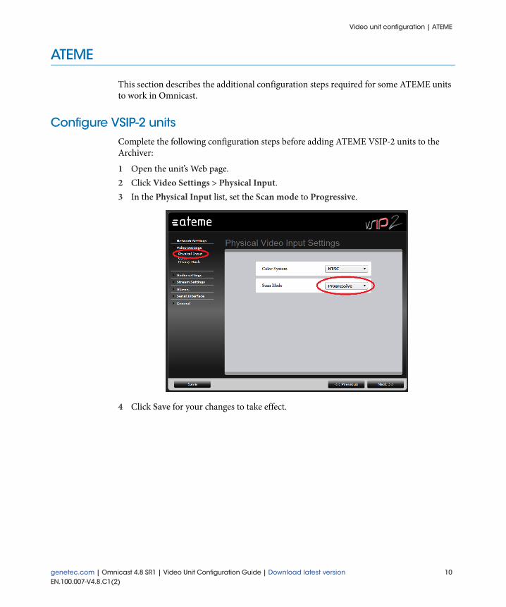
This section describes the additional configuration steps required for some ATEME units to work in Omnicast.
Configure VSIP-2 unitsComplete the following configuration steps before adding ATEME VSIP-2 units to the Archiver:
1 Open the unit’s Web page.2 Click Video Settings > Physical Input.3 In the Physical Input list, set the Scan mode to Progressive.
4 Click Save for your changes to take effect.
genetec.com | Omnicast 4.8 SR1 | Video Unit Configuration Guide | Download latest version 10EN.100.007-V4.8.C1(2)

Video unit configuration | Axis
Axis
This section describes the additional configuration steps required for some Axis unit features to work in Omnicast.
This section includes the following topics:
• "Configure Axis H.264 cameras" on page 11• "Configure recording schedules" on page 11• "Configure trickling for Axis units" on page 12• "Configuring the Axis T8310 Video Surveillance Control Board" on page 15• "Configure multi-view areas" on page 21• "Creating PTZ patterns" on page 22
Configure Axis H.264 camerasTo increase the image quality and decrease the bit rate for Axis H.264 video streams, the recording stream can be configured to use the Main profile in Config Tool.
NOTE The Main profile is only supported on some Axis H.264 models. If the Profile option is not available in Config Tool, then the camera does not support the profile selection feature.
1 From the Physical view in Config Tool, select a camera to configure.2 Click the Video Quality tab, click the stream1 tab.3 From the Profile drop-down list, select Main profile.4 Click Apply.
Configure recording schedulesBest practice: For Axis units with firmware prior to version 5.40, it is best practice to create scheduled events using the unit’s Web page, instead of using the Continuous Recording setting in Config Tool. The shorter the sequence the better; therefore, it is also recommended to create multiple scheduled events per day rather than one large one.
11 genetec.com | Omnicast 4.8 SR1 | Video Unit Configuration Guide | Download latest versionEN.100.007-V4.8.C1(2)

Video unit configuration | Axis
Configure trickling for Axis unitsTo use trickling with Axis units, it is recommended to configure following settings in Con-fig Tool and on the unit’s Web page.
For more information about configuring trickling, see “Trickling” in the Omnicast Administrator Guide.
Best practice: To improve readability when trickling with Axis units, use an SDHC mem-ory card or an SD card with a speed class of four or higher, and use H.264 streaming.
1 From the Physical view in Config Tool, select the Archiver to configure.2 Click the Trickling tab, and click Properties.3 In the Trickling Properties dialog box, do the following:
a Select the following Trickling filters: Motion and Bookmarks.b Set the Event download pre-roll slider value to 6 seconds or higher.c Set the Event download post-roll slider value to 6 seconds or higher.d Click OK.
4 From the Physical view in Config Tool, select the Axis camera to configure, and click the Recording tab.
5 Clear the selected Archiving shedules, and click Apply.6 Click the Motion detection tab.7 From the Motion detection drop-down list, select Full screen (Unit).8 Configure the Sensitivity, Motion on threshold, and Motion off threshold settings as
desired.
genetec.com | Omnicast 4.8 SR1 | Video Unit Configuration Guide | Download latest version 12EN.100.007-V4.8.C1(2)

Video unit configuration | Axis
9 Click Apply.10 Open the unit’s Web page.11 Click Setup > Events > Event Types.
12 In the Event Types page, select an event type, and click Modify.13 In the Respond to Trigger section of the Trigger Event Type Setup dialog box, select
the Never (event type disabled) option.14 Click OK.
The Enabl. column for the event type is set to No.15 Repeat Step 12 to Step 14 for each event type in the Event Type List.
13 genetec.com | Omnicast 4.8 SR1 | Video Unit Configuration Guide | Download latest versionEN.100.007-V4.8.C1(2)

Video unit configuration | Axis
16 Click Recordings > Continuous.
17 In the Recording Settings section of the Continuous Recording page, select the Enable option.
18 In the Disk field, select SD Card or Network share.19 From the Stream profile drop-down list, select Balanced.20 Click Save.21 Click System Options > Storage > Overview.
genetec.com | Omnicast 4.8 SR1 | Video Unit Configuration Guide | Download latest version 14EN.100.007-V4.8.C1(2)

Video unit configuration | Axis
22 Depending on the setting you selected in Step 18, click Network Share or SD Card.
23 In the Storage Management page, select Enable automatic disk cleanup.24 Set the Remove recordings older than field to 3 days.
TIP Depending on your SD card, you can use a higher value.
25 If you selected SD card in Step 18, make sure the File system field is set to ext4.26 Click OK.
The first recording entry under the Recordings tab should be Continuous.
Configuring the Axis T8310 Video Surveillance Control BoardThe Axis T8310 Video Surveillance Control Board system allows you to control PTZ motors, switch between cameras, control playback, customize peripheral buttons, etc. It consists of three units that can be installed together, or as separate peripherals in the Live Viewer or Archive Player:
• AXIS T8311. A joystick that allows you to accurately control the pan/tilt/zoom func-tions of cameras on the network. It has three customizable axis, six customizable but-tons, and is configured like any other joystick.
15 genetec.com | Omnicast 4.8 SR1 | Video Unit Configuration Guide | Download latest versionEN.100.007-V4.8.C1(2)
Video unit configuration | Axis
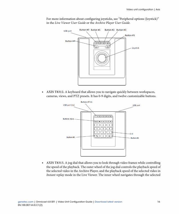
For more information about configuring joysticks, see “Peripheral options (Joystick)” in the Live Viewer User Guide or the Archive Player User Guide.
• AXIS T8312. A keyboard that allows you to navigate quickly between workspaces, cameras, views, and PTZ presets. It has 0-9 digits, and twelve customizable buttons.
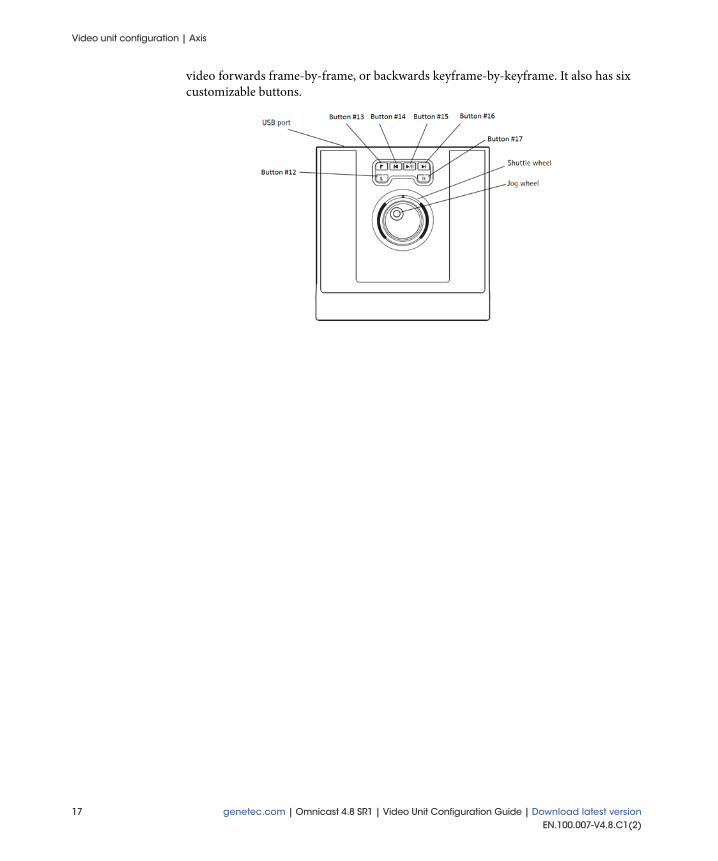
• AXIS T8313. A jog dial that allows you to look through video frames while controlling the speed of the playback. The outer wheel of the jog dial controls the playback speed of the selected video in the Archive Player, and the playback speed of the selected video in Instant replay mode in the Live Viewer. The inner wheel navigates through the selected
genetec.com | Omnicast 4.8 SR1 | Video Unit Configuration Guide | Download latest version 16EN.100.007-V4.8.C1(2)
Video unit configuration | Axis
video forwards frame-by-frame, or backwards keyframe-by-keyframe. It also has six customizable buttons.
17 genetec.com | Omnicast 4.8 SR1 | Video Unit Configuration Guide | Download latest versionEN.100.007-V4.8.C1(2)

Video unit configuration | Axis
The AXIS T8312 and the AXIS T8313 can be used together as one external keyboard, and associated to Archive Player commands of your choice. The 12 customizable buttons on the T8312 keyboard are mapped first, followed by the 6 buttons on the T8313 jog dial.
Before you begin: If the CCTV keyboard is currently being used in another client applica-tion, disconnect it.
• In the Live Viewer or Archive Player, click System > Deactivate CCTV keyboard.
To configure the Axis CCTV keyboard:1 In the Live Viewer or Archive Player, click the Home button, and click Tools > Options
> Peripherals > Keyboard.2 From the Keyboard protocol drop-down list, select Axis Control Board.3 From the Button list, select a button to configure, and click the edit button under
the Down command field to see a list of commands you can choose from.
You can also associate two different commands to each button, one for the button down event and another for the button up event. The Up command is optional.
4 To erase the selected command mapping, click the Clear button.5 In the application’s main window, click System > Activate CCTV Keyboard.
genetec.com | Omnicast 4.8 SR1 | Video Unit Configuration Guide | Download latest version 18EN.100.007-V4.8.C1(2)

Video unit configuration | Axis
NOTE If the CCTV keyboard is still being used by another client application, you will get the following warning message. Disconnect the keyboard from the other application.
The Axis CCTV keyboard is now ready to use in the Live Viewer or Archive Player.
The default key map for the external keyboard in the Archive Player is the following:
Button in Archive Player Button on Axis units Down command
0 on Axis keyboard Cycle pattern next
1 ALT on Axis keyboard Expand/Collapse selected tile
2 on Axis keyboard listen (on/off)
6 on Axis keyboard Remove tile
12 L on Axis joystick Rewind
13 on Axis joystick Add bookmark
14 on Axis joystick Previous keyframe
15 on Axis joystick Play/Pause
16 on Axis joystick Next frame
17 R on Axis joystick Fast forward
19 genetec.com | Omnicast 4.8 SR1 | Video Unit Configuration Guide | Download latest versionEN.100.007-V4.8.C1(2)

Video unit configuration | Axis
The default key map for the external keyboard in the Live Viewer is the following:
NOTE When you are using the Axis CCTV keyboard and the selected command requires an argument, enter it using the nine digits on the AXIS T8312 keyboard. For example, if you want to select camera 12, press the following on the CCTV keyboard:
• Press 1, press 2, and then press the default Live Viewer button 3 .
Button in Live Viewer Button on Axis units Down command
0 on Axis keyboard Cycle next used tile
1 ALT on Axis keyboard Expand/Collapse selected tile
2 on Axis keyboard Select tile/monitor
3 on Axis keyboard Select camera/layout
4 on Axis keyboard Switch to digital zoom
5 on Axis keyboard Switch to instant replay
6 on Axis keyboard Acknowledge alarm
7 F1 on Axis keyboard Launch hot marco 01
8 F2 on Axis keyboard Launch hot macro 02
9 F3 on Axis keyboard Launch hot macro 03
10 F4 on Axis keyboard Launch hot macro 04
11 F5 on Axis keyboard Launch hot macro 05
12 L on Axis joystick Instant Replay - Rewind
13 on Axis joystick Add bookmark
14 on Axis joystick Instant Replay - Previous keyframe
15 on Axis joystick Instant Replay - Play/Pause
16 on Axis joystick Instant Replay - Next frame
17 R on Axis joystick Instant Replay - Fast forward
genetec.com | Omnicast 4.8 SR1 | Video Unit Configuration Guide | Download latest version 20EN.100.007-V4.8.C1(2)

Video unit configuration | Axis
Configure multi-view areasThe Axis multi-view feature enables the creation of additional streams by cropping the camera’s field of view. Additional configuration is required for the Axis multi-view feature to work in Omnicast.
1 Open the unit’s Web page.2 Click Setup > Video & Audio > View Areas.
3 Click the Add button.A new view area is created (Example: View Area 1).
4 Select the location and size of the new view area. You can modify the view area size by dragging the lower-right corner of the selected area.
5 Set the Aspect ratio to 4:3, 16:9, or 11:9. 6 Select the appropriate Video stream resolution for the area size.
IMPORTANT You must manually set the video stream resolution in Omnicast to match the resolution set in the unit's Web page for the multi-view feature to work.
7 Click Save. 8 Do one of the following:
If the unit is not yet part of the Omnicast system, add it to in the Archiver. For infor-mation on about adding video units in Omnicast, see “Adding video units” in the Omnicast Administrator Guide.
If the unit is already in the Omnicast system, restart the Archiver to update your changes.
21 genetec.com | Omnicast 4.8 SR1 | Video Unit Configuration Guide | Download latest versionEN.100.007-V4.8.C1(2)

Video unit configuration | Axis
Creating PTZ patternsPTZ patterns can be created for some Axis cameras through the guard tour feature. An Axis guard tour is similar to an Omnicast PTZ pattern; it is a series of presets (including camera position, iris, and focus settings) which can run in the Live Viewer or Config Tool the same as any other PTZ pattern. Refer to your Axis camera’s documentation for more information on guard tours.
Configure PTZ patterns
Once an Axis camera that supports the guard tour feature is added in Omnicast, ten empty patterns are automatically created, initially named “0 - Untitled” through “10 - Untitled”. These patterns can then be renamed in the Config Tool, and configured in the Axis camera’s Web page.
IMPORTANT Do not create new patterns or rename patterns in the Axis camera’s Web page. This will result in unusable patterns. Instead, perform all of these actions in Omnicast.
Before you begin: The following is required to configure PTZ patterns in Omnicast:
• The Axis camera you are using must have the guard tour feature, and be running firm-ware version 4.40 or later. For a list of Axis cameras that currently support this feature, see the Supported Devices list on Genetec’s Technical Assistance Portal (GTAP): https://gtap.genetec.com/Library/SupportedDevices.aspx. Please note that you’ll be required to login using your e-mail address and password.
• Standard user privileges for working with PTZ patterns must be enabled.
To rename PTZ patterns:1 From the Physical view in Config Tool, select the Axis camera that contains the PTZ
patterns you want to rename.2 Click the Test tab. 3 In the PTZ advanced mode commands, select the pattern you want to rename from the
Pattern drop-down list.4 Click the Rename button.5 In the dialog box that appears, enter a new name for the pattern.6 Click OK.
The pattern’s new name is reflected in Omnicast and in the Axis camera’s Setup config-uration Web page.
7 Repeat Step 1 to Step 6 for each pattern to be configured.
genetec.com | Omnicast 4.8 SR1 | Video Unit Configuration Guide | Download latest version 22EN.100.007-V4.8.C1(2)

Video unit configuration | Axis
To configure Axis guard tours:1 Open the Axis camera’s Web page.2 Follow the Axis documentation that comes with your camera to configure the Axis
guard tours (PTZ patterns renamed in Omnicast). NOTE Since Omnicast creates empty Axis guard tours (PTZ patterns) when the camera is added, when you configure the guard tours in the camera’s Web page you are modifying the existing Omnicast presets as opposed to adding new ones.
The configured Axis guard tours become available in Omnicast to use as PTZ patterns for the camera.
After you are done: Test the Axis PTZ patterns in Omnicast. They should run the same way as other PTZ patterns.
Edit PTZ presets
You can edit presets that are used in PTZ patterns on Axis cameras. When you make a change to a preset, it is immediately reflected in the PTZ pattern.
IMPORTANT Make all of your changes in Omnicast, not in the camera’s Web page.
WARNING Do not click the Clear button in the Config Tool when editing a preset. Clearing presets that are included in PTZ patterns on Axis cameras removes all following presets from the pattern, and prevents any further edits to the pattern. Instead, overwrite an existing preset by recording over it or editing it, as described in the procedure below.
1 In the PTZ advanced mode commands in Config Tool or Live Viewer, select the preset you want to edit from the Presets drop-down list.
2 With the PTZ controls, adjust the camera position, iris, zoom, and focus settings to the desired positions.If you are working in the Live Viewer, you can also click inside the tile and move the camera to a new position.
3 Click the Set button.The current position and settings of the camera are recorded. Changes to the preset are reflected for all PTZ patterns that use this preset on the Axis camera.If a PTZ pattern using the preset is currently playing, it stops. If necessary, restart it. At this point changes to the preset take effect.
23 genetec.com | Omnicast 4.8 SR1 | Video Unit Configuration Guide | Download latest versionEN.100.007-V4.8.C1(2)

Video unit configuration | Basler
Basler
This section describes the additional configuration steps required for some Basler units and features to work in Omnicast.
This section includes the following topics:
• "Change the default port for input pin events" on page 24• "Configuring Basler BIP2 units" on page 25• "Configure Basler BIP2-640c-dn units" on page 27
Change the default port for input pin eventsIn order to receive input pin events from Basler units, the Archiver needs to open a TCP port for its HTTP server. The default port is 8081. If this port is already in use on the Archiver machine, you can change the default port.
To change the default port:1 On the Archiver machine, navigate to the installation directory, located in C:\Program
Files\Common Files\DVR Software 4.8\Extensions\Drivers\ on 32-bit machines, and C:\Program Files (x86)\Common Files\DVR Software 4.8\Extensions\Drivers\ on 64-bit machines.
2 Open the BaslerDriverConfiguration.xml file in Notepad.Text similar to the following is displayed:
<BaslerDriverConfiguration>
<HttpServerPort>8081</HttpServerPort>
</BaslerDriverConfiguration>
3 Change the value of the HttpServerPort from 8081 to something else, such as 8082.NOTE The value for the HttpServerPort must be the same for all standby Archivers associated with the unit.
4 Save the file, and restart the Archiver.
genetec.com | Omnicast 4.8 SR1 | Video Unit Configuration Guide | Download latest version 24EN.100.007-V4.8.C1(2)

Video unit configuration | Basler
Configuring Basler BIP2 unitsComplete the following configuration steps before adding Basler BIP2 units in Omnicast.
Reset the factory default settings1 Open the unit's Web page.2 Click Configuration > Camera Configuration > System.3 In the Management tab, click Reset to Factory Defaults.
4 Click OK to apply your changes.
After you are done: Basler BIP2 video streams must also be configured to use different encoder types for the units to work in Omnicast.
25 genetec.com | Omnicast 4.8 SR1 | Video Unit Configuration Guide | Download latest versionEN.100.007-V4.8.C1(2)

Video unit configuration | Basler
Set the video stream encoder types1 Open the unit's Web page.2 Click Configuration > Camera Configuration > Streaming.3 In the Stream0 tab, set the Encoder Type to MJPEG.4 In the Stream1 tab, set the Encoder Type to H.264 Base Profile or H.264 High Pro-
file.
5 In the Stream2 tab, set the Encoder Type to MPEG4.6 Close the Streaming section of the unit's Web page to apply your settings.
genetec.com | Omnicast 4.8 SR1 | Video Unit Configuration Guide | Download latest version 26EN.100.007-V4.8.C1(2)

Video unit configuration | Basler
Configure Basler BIP2-640c-dn unitsFor Basler BIP2-640c-dn units to work at a high frame rate, additional configuration steps are required in Omnicast.
To configure H.264 streams at 100 fps:1 The camera must be configured for a sensor frame rate of 100 fps.2 Stream0 of the camera must be configured for MJPEG, and a frame rate scaling of 1/8
(meaning Stream0 would yield only 12.5 fps).3 Stream1 must be configured for H.264.4 Stream2 must be switched off (the user cannot use MPEG4 simultaneously).Depending on the complexity and the amount of movement in the scene, the frame rate may drop from 100 to 95. This happens particularly if the camera's text overlays are activated.
To configure MJPEG streams at 60 fps:1 The camera must be configured for a sensor frame rate of 60 fps.2 Stream0 of the camera must be configured for MJPEG.3 Stream1 and Stream2 must be switched off (the user cannot use H.264 or MPEG4
simultaneously).
27 genetec.com | Omnicast 4.8 SR1 | Video Unit Configuration Guide | Download latest versionEN.100.007-V4.8.C1(2)

Video unit configuration | Bosch
Bosch
This section describes the additional configuration steps required for some Bosch units and unit features to work in Omnicast.
This section includes the following topics:
• "Configure video analytics" on page 28• "Configuring Bosch H.264 units" on page 29• "Configuring Bosch Divar 700 DVRs" on page 31• "Configuring Bosch VRM units" on page 33• "Configure the Bosch Intuikey CCTV keyboard" on page 35
Configure video analyticsBefore you begin: For video analytics (IVA) to work on Bosch units in Omnicast, you will require the following:
• A valid video analytics license from the manufacturer must be installed on the unit.
• Your Omnicast license must support edge analytics cameras. NOTE The video analytics rules for the unit can only be configured using the Bosch Configuration Manager. To use the Bosch Configuration Manager, you will need a valid license from the manufacturer, and ActiveX must be installed.
To configure video analytics for Bosch units:1 Open the Bosch Configuration Manager.2 In the Network tab, select the unit to configure.3 Click Alarm, and click the VCA tab.4 From the Analysis type drop-down list, select the video analytics type you have a
license for.5 Click the Configuration button.6 In the IVA Wizard window, make any required changes to the video analytics rule con-
figuration, and click OK.
If your unit was already part of the Omnicast system, restart the Archiver for your changes to take effect.
genetec.com | Omnicast 4.8 SR1 | Video Unit Configuration Guide | Download latest version 28EN.100.007-V4.8.C1(2)

Video unit configuration | Bosch
Configuring Bosch H.264 unitsThis section describes the additional configuration steps required for some Bosch H.264 unit features to work in Omnicast.
Enable software motion detection
For software motion detection to work with select Bosch cameras using H.264 streaming in non-HD resolution, the recording stream must be configured to use the Baseline Pro-file+ profile in Omnicast.
NOTE The Baseline Profile+ is supported on most Bosch H.264 models with firmware 4.20 and later.
1 From the Physical view in Config Tool, select a camera to configure.2 In the Video Quality tab, click the stream1 tab.3 From the Profile drop-down list, select H.264 BP+.
NOTE The Baseline Profile+ is not available for HD resolutions.
4 Click Apply to save your changes.
29 genetec.com | Omnicast 4.8 SR1 | Video Unit Configuration Guide | Download latest versionEN.100.007-V4.8.C1(2)

Video unit configuration | Bosch
Enable 60 frames per second
For select Bosch H.264 units to stream video at a frame rate of 60 frames per second, the recording stream must be configured to use the H.264 MP fixed 720p full framerate profile.
NOTE If the unit has two H.264 video streams, the settings for stream2 are limited to the settings specified for stream1.
1 From the Physical view in Config Tool, select a camera to configure.2 In the Video Quality tab, click the stream 1 tab.3 From the Video data format drop-down list, select H.264 1280 x 720.4 From the Quality drop-down list, select Custom.5 From the Profile drop-down list, select H.264 MP fixed 720p full framerate.
The Frame rate values available increase from 30 fps to 60 fps.6 Change the Frame rate value to 60 fps.7 Click Apply to save your changes.
genetec.com | Omnicast 4.8 SR1 | Video Unit Configuration Guide | Download latest version 30EN.100.007-V4.8.C1(2)
Video unit configuration | Bosch
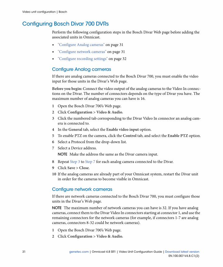
Configuring Bosch Divar 700 DVRsPerform the following configuration steps in the Bosch Divar Web page before adding the associated units in Omnicast.
• "Configure Analog cameras" on page 31
• "Configure network cameras" on page 31
• "Configure recording settings" on page 32
Configure Analog camerasIf there are analog cameras connected to the Bosch Divar 700, you must enable the video input for those units in the Divar’s Web page.
Before you begin: Connect the video output of the analog cameras to the Video In connec-tions on the Divar. The number of connectors depends on the type of Divar you have. The maximum number of analog cameras you can have is 16.
1 Open the Bosch Divar 700’s Web page.2 Click Configuration > Video & Audio.3 Click the numbered tab corresponding to the Divar Video In connector an analog cam-
era is connected to.4 In the General tab, select the Enable video input option.5 To enable PTZ on the camera, click the Control tab, and select the Enable PTZ option.6 Select a Protocol from the drop-down list.7 Select a Device address.
NOTE Make the address the same as the Divar camera input.
8 Repeat Step 3 to Step 7 for each analog camera connected to the Divar.9 Click Save > Close.10 If the analog cameras are already part of your Omnicast system, restart the Divar unit
in order for the cameras to become visible in Omnicast.
Configure network camerasIf there are network cameras connected to the Bosch Divar 700, you must configure those units in the Divar’s Web page. NOTE The maximum number of network cameras you can have is 32. If you have analog cameras, connect them to the Divar Video In connectors starting at connector 1, and use the remaining connectors for the network cameras (for example, if connectors 1-7 are analog cameras, connectors 8-32 could be network cameras).
1 Open the Bosch Divar 700’s Web page.2 Click Configuration > Video & Audio.
31 genetec.com | Omnicast 4.8 SR1 | Video Unit Configuration Guide | Download latest versionEN.100.007-V4.8.C1(2)

Video unit configuration | Bosch
3 Click the numbered tab corresponding to a Video In connector for a network camera.4 In the General tab, select the Enable video input option.5 Do one of the following:
Click the [Manual setup] button, and type the IP address, Input, Stream, and Pass-word information of the camera.
Click the [Auto detect] button if the feature is available for that camera.6 To enable PTZ on the camera, click the Control tab, and select the Enable PTZ option7 Select a Protocol from the drop-down list.8 Select a Device address.
NOTE The address must be unique. It is recommended to use the same number as the input the camera is connected to.
9 Repeat Step 3 to Step 8 for each network camera connected to the Divar.10 Click Save > Close.11 If the network cameras are already part of your Omnicast system, restart the Divar unit
in order for the cameras to become visible in Omnicast.
Configure recording settings
The Bosch Divar 700 can have a maximum of six recording profiles that you can use with the enabled cameras.
IMPORTANT If the Recording on the edge only option is selected in the Recording tab of the cameras in Omnicast, the Archiver will not record locally. In order to transfer video recordings from the Divar, video trickling must be enabled. For more information about trickling recorded video, see “Trickling” in the Omnicast Administrator Guide.
NOTE There can only be one active profile at a time. The selected profile is used for every camera connected to the Divar.
1 Open the Bosch Divar 700’s Web page.2 Click Configuration > Recording.3 Click a Profile tab.4 Click the numbered tab corresponding to the cameras connected to the Divar.5 Do one of the following:
To record continuously or on a schedule, click the Normal tab.NOTE The Normal tab determines the Divar recording settings when that profile is active. The resolution and frame rate settings cannot be configured in the Normal tab; they will be overridden by the recording settings configured in Omnicast.
i Select a Normal recording mode (Continuous rec. or Events only).ii From the Quality drop-down list, select a recording quality value.
genetec.com | Omnicast 4.8 SR1 | Video Unit Configuration Guide | Download latest version 32EN.100.007-V4.8.C1(2)

Video unit configuration | Bosch
This setting will affect the quality and bandwidth of the video streams coming from the Divar to Omnicast.
To record on contact, click the Contact tab.NOTE If recording on Contact is selected, the recording settings configured on the Divar will override the Omnicast settings.
iii Select a Contact recording mode (Follows, Follows + post, or Fixed duration).iv Select the Duration, Resolution, Quality, and Frame rate for the recording
stream. To record on motion, click the Motion tab.
NOTE If recording on Motion is selected, the recording settings configured on the Divar will override the Omnicast settings.
v Set the Motion recording mode to Fixed duration.vi Select the Duration, Resolution, Quality, and Frame rate for the recording
stream.6 Repeat Step 3 to Step 5 for each recording profile you want to create, and for each unit
using that profile.7 To set when each recording profile is active, click Configuration > Schedule > Sched-
ule from the Divar’s home page.8 Select a profile, and set the date and time that profile should record.
NOTE These schedules are independent of Omnicast schedules.
9 Click Save > Close.
Configuring Bosch VRM unitsBest practice: For optimal performance, it is best practice to set the playback mode for Bosch VRM (Video Recording Manager) units to use iSCSI connection, which is a storage unit for network drives.
To use the iSCSI connection playback mode, make sure that all Archiver servers and cameras recording on the iSCSI have full read access to all iSCSI storage units managed by the Bosch VRM. For more information, please refer to the storage vendor’s documentation.
33 genetec.com | Omnicast 4.8 SR1 | Video Unit Configuration Guide | Download latest versionEN.100.007-V4.8.C1(2)

Video unit configuration | Bosch
Enable audio recording
To play back and export Bosch VRM video recordings with both audio and video, you must enable audio recording on the unit using the Bosch VRM Configurator.
Before you begin: Make sure that the audio source is connected to the LineIn connector on the video unit.
1 Open the Bosch VRM Configurator.2 Click System > Devices.3 From the Devices list, select the unit to configure.4 Click the Recording > Recording Profiles > Day tabs.
NOTE If you want the unit to record audio at a different time, select a different day/time tab to configure.
5 Next to the Recording includes field, select the Audio option.6 Apply your changes.If the unit is already part of your Omnicast system and is currently recording, restart the unit.
genetec.com | Omnicast 4.8 SR1 | Video Unit Configuration Guide | Download latest version 34EN.100.007-V4.8.C1(2)

Video unit configuration | Bosch
Configure the Bosch Intuikey CCTV keyboardThe top four buttons on Bosch Intuikey CCTV keyboards can control the Play, Pause, Next, and Previous commands of a camera sequence in the Live Viewer. The default button association is the following:
You must configure the Bosch Intuikey CCTV keyboard before using it in the Live Viewer.
Before you begin: Make sure that the RS-232 port of the Bosch Intuikey CCTV keyboard is connected to the COM port of the computer.
1 In the Live Viewer, click Tools > Options > Peripherals > Keyboard tab.
2 From the Keyboard protocol drop-down list, select Bosh Intuikey.3 From the Communication port drop-down list, select the COM port you just con-
nected the keyboard to.
Button on Bosch keyboard Command in Live Viewer
Pause Pause
Play Play/Resume
FF Show next camera in the sequence
REW Show previous camera in the sequence
35 genetec.com | Omnicast 4.8 SR1 | Video Unit Configuration Guide | Download latest versionEN.100.007-V4.8.C1(2)

Video unit configuration | Bosch
4 From the Data bits drop-down list, select 8.5 From the Parity drop-down list, select None.6 From the Stop bits drop-down list, select 1.7 From the Baud rate drop-down list, select 19200.8 Click Apply, and click OK.9 In the Live Viewer, click System > Activate CCTV keyboard.
The keyboard is ready to use. For more information about camera sequences, see “Viewing a camera sequence” in the Omnicast Live Viewer User Guide.
You can also connect the Bosch Intuikey CCTV keyboard to a video unit, so it can control that specific unit in the Live Viewer.
Before you begin: Make sure that the RS-232 port of the Bosch Intuikey CCVT keyboard is connected to the serial port of the video unit.
1 In the Physical view of the Config Tool, click Add, select Virtual Matrix Manage-ment, and click CCTV keyboard.
2 Select the new CCTV keyboard in the entity tree, and click the Properties tab.
3 From the Serial port drop-down list, select the unit and port that the keyboard is con-nected to.
4 From the Keyboard protocol drop-down list, select Bosh Intuikey.
genetec.com | Omnicast 4.8 SR1 | Video Unit Configuration Guide | Download latest version 36EN.100.007-V4.8.C1(2)

Video unit configuration | Bosch
5 In the Live Viewer list, select the Live Viewer application where you want the Bosch Intuikey CCTV keyboard to control the unit.
6 Click Apply.7 In the entity tree under the unit that is connected to the keyboard, select the unit’s serial
port.8 Click the Properties tab.9 From the Data bits drop-down list, select 8.10 From the Parity drop-down list, select None.11 From the Stop bit drop-down list, select 1.12 From the Baud rate drop-down list, select 19200.13 Click Apply to save your changes.
37 genetec.com | Omnicast 4.8 SR1 | Video Unit Configuration Guide | Download latest versionEN.100.007-V4.8.C1(2)

Video unit configuration | Canon
Canon
This section describes the additional configuration steps required for some Canon units and features to work in Omnicast.
Configuring Canon VB-C60 and VB-C500D unitsThis section describes the additional configuration steps required for Canon VB-C60 and VB-C500D units to work in Omnicast.
This section includes the following topics:
• "Grant user access" on page 38• "Enable MJPEG streaming" on page 38• "Enable PTZ control for VB-C60 units" on page 39
Grant user access
To control Canon VB-C60 and VB-C500D units in Omnicast, you must grant the Omni-cast user access to the unit using the unit’s Web page.
1 Open the Unit’s Web page.2 Click Access Control > Maintenance.3 In the User Authority section, select the Privileged Camera Control, Camera Con-
trol, and Image Distribution options for the Authorized User.4 Click Apply.
Enable MJPEG streaming
To stream MJPEG video in Omnicast with Canon VB-C60 and VB-C500D units, you need to configure the stream settings from the unit’s Web page.
1 Open the unit’s Web page.2 Click Video > Maintenance.3 In the MJPEG section, configure the Video Quality, Video Size (resolution), and Cap-
ture Frame Rate settings.IMPORTANT If you change the Video Size setting, you must restart the MPJEG video stream.
4 Click Apply.
genetec.com | Omnicast 4.8 SR1 | Video Unit Configuration Guide | Download latest version 38EN.100.007-V4.8.C1(2)

Video unit configuration | Cisco
Enable PTZ control for VB-C60 unitsIMPORTANT To use PTZ presets with Canon VB-C60 units in Omnicast, you must create PTZ presets for the unit using the Preset Setting Tool (one of the Canon VB Administration tools) before the unit to the Archiver. For more information about creating PTZ presets for Canon units, see the Canon manufacturer documentation.
Cisco
Before adding Cisco 2500 series units in your Omnicast system, the stream type and video settings must be configured in the unit’s Web page.
1 Open the unit’s Web page.2 Enter the unit username and password.3 Click Setup > Audio/Video > Video.
4 From the Streaming Mode Combination drop-down list, select the desired stream type.
5 Make any other changes to the video settings for the stream type you selected.6 Click Save.
39 genetec.com | Omnicast 4.8 SR1 | Video Unit Configuration Guide | Download latest versionEN.100.007-V4.8.C1(2)

Video unit configuration | Comtex
Comtex
This section describes the additional configuration steps required for some Comtex units to work in Omnicast.
Configure WB-H811 unitsComplete the following configuration steps before adding the unit to the Archiver:
1 Open the unit’s Web page.2 Click Video Settings.3 Under Streaming 1 Settings:
Set the Video Format to H.264. Set the RTSP Path to v1h264 (this field is case sensitive).
4 Click Apply.
Configure PTZ for WB-H811 units
If you want to use PTZ with the Comtex WB-811unit, the PTZ protocol, Camera ID, and Baud rate must be set using the unit’s Web page.
genetec.com | Omnicast 4.8 SR1 | Video Unit Configuration Guide | Download latest version 40EN.100.007-V4.8.C1(2)
Video unit configuration | Dynacolor
Dynacolor
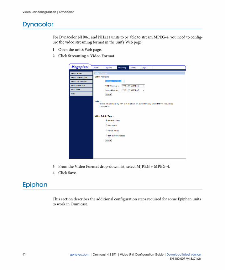
For Dynacolor NH061 and NH221 units to be able to stream MPEG-4, you need to config-ure the video streaming format in the unit’s Web page.
1 Open the unit’s Web page.2 Click Streaming > Video Format.
3 From the Video Format drop-down list, select MJPEG + MPEG-4.4 Click Save.
Epiphan
This section describes the additional configuration steps required for some Epiphan units to work in Omnicast.
41 genetec.com | Omnicast 4.8 SR1 | Video Unit Configuration Guide | Download latest versionEN.100.007-V4.8.C1(2)

Video unit configuration | Epiphan
Configure VGA Broadcaster Lite unitsThe following stream configuration steps are required for Epiphan VGA Broadcaster Lite units to work in Omnicast.
1 Open the unit's Web page.2 Click Configuration > Stream Setup.
3 From the Stream type drop-down list, select RTSP (H.264 codec). 4 Under RTP/UDP stream, deselect the Enable RTP/UDP stream option.5 To prevent tearing during playback, select the Enhanced compatibility mode option
under RTP/UDP stream.6 Configure any other video settings as necessary.7 For motion detection to work properly, set a high Bitrate value according to the resolu-
tion and frame rate you selected.8 Click Apply.
genetec.com | Omnicast 4.8 SR1 | Video Unit Configuration Guide | Download latest version 42EN.100.007-V4.8.C1(2)

Video unit configuration | Interlogix
Interlogix
This section describes the additional configuration steps required for some Interlogix units to work in Omnicast.
This section includes the following topics:
• "Configure Discovery 105-E (UVE-101) units" on page 43• "Configuring VisioWave units" on page 44
Configure Discovery 105-E (UVE-101) unitsThe following configuration must be performed before adding Discovery 105-E (UVE-101) units in Omnicast.
1 Open the unit’s Web page.2 Click Administration.3 Enter you username and password.4 Click Video port format.
5 Set the Video port format to NTSC M or PAL depending on the camera connected to the encoder.
6 Click OK to save your changes.
43 genetec.com | Omnicast 4.8 SR1 | Video Unit Configuration Guide | Download latest versionEN.100.007-V4.8.C1(2)

Video unit configuration | Interlogix
Enable software motion detection
To enable software motion detection for Interlogix Discovery 105-E (UVE-101) units in Omnicast, additional configuration is required in Config Tool.
1 From the Physical view in Config Tool, select the camera to configure.2 Click the Motion detection tab.3 Set the Sensitivity slider to 20%.4 Click the Advanced button.5 From the Preset drop-down list in the H.264 Advanced motion detection settings
dialog box, select Custom.6 Under Custom, set the following values:
Luma weight: 5 Chroma weight: 0 Vectors weight: 0 Macroblocks weight: 100
7 Click Close, and click Apply.For more information about advanced motion detection settings, see “Advanced H.264 Motion Detection” the Omnicast Administrator Guide.
Configuring VisioWave unitsThe Interlogix VisioWave driver can control multiple Interlogix units and PTZ motors. You must add and configure Interlogix VisioWave units using the Central Configuration Server application.
Before you begin: Make sure the Interlogix Central Configuration Server is installed.
Best practice: Perform these configuration steps before adding the unit to the Archiver.
• Step 1: Add VisioWave units
• Step 2: Configure video ports
• Step 3: Enable PTZ
Step 1: Add VisioWave units1 Open the Central Configuration Server in Internet Explorer.2 Click Equipment > New Video Equipment.3 Enter the following information:
a In the Equipment name field, type a name for the unit.b In the IP Address field, type the IP address of the unit.
genetec.com | Omnicast 4.8 SR1 | Video Unit Configuration Guide | Download latest version 44EN.100.007-V4.8.C1(2)

Video unit configuration | Interlogix
c From the Product Hardware Range drop-down list, select the unit type (for exam-ple, EVOLUTION HD, or DISCOVERY 300).NOTE The number of inputs available depends on the unit type.
4 Click Next until the Serial Ports page.5 Enter the following information:
a Type a name for the first serial port.b From the Port drop-down list, select COM1.c Type RS485 HALF DUPLEX.
6 Click Next > Next > OK.7 Click Apply in the top-right corner of the Central Configuration Server window.
When your changes are applied, a confirmation appears in the window. 8 Click OK.
45 genetec.com | Omnicast 4.8 SR1 | Video Unit Configuration Guide | Download latest versionEN.100.007-V4.8.C1(2)

Video unit configuration | Interlogix
Step 2: Configure video ports1 Open the Central Configuration Server in Internet Explorer.2 Click Equipment.3 In the Equipment list, select the unit to configure.4 Click Video Inputs.5 Click the input name you want to use.6 Under ENABLE UDP in the Network section, clear the ALLOW IP FRAGMENTA-
TION option.7 Select the Input format you want to use, and click OK.8 Click Apply in the upper-right corner of the Central Configuration Server window.
When your changes are applied, a confirmation appears in the window. 9 Click OK.
Step 3: Enable PTZ
To enable PTZ for VisioWave units, you must create a new PTZ camera for the unit’s serial port in the Central Configuration Server.
1 Open the Central Configuration Server in Internet Explorer.2 Click Equipment.3 In the List of Video Equipment, select the unit to configure.4 Click Serial Ports.5 Select the serial port you created in "Step 1: Add VisioWave units" on page 44, and con-
figure it the same as the serial configuration of the camera.6 Click Ok.7 Click Apply in the top-right corner of the Central Configuration Server window.
When your changes are applied, a confirmation appears in the window. 8 Click OK.
genetec.com | Omnicast 4.8 SR1 | Video Unit Configuration Guide | Download latest version 46EN.100.007-V4.8.C1(2)

Video unit configuration | Interlogix
9 In the Central Configuration Server main page, click Equipment.
10 In the List of Video Equipment, select the unit to configure.11 Click Serial Ports.12 In the List of Serial Ports for Video Equipment, select the serial port you created in
"Step 1: Add VisioWave units" on page 44.13 Click PTZ Cameras > New PTZ camera.14 In the New PTZ Camera for Serial Port x page, do the following:
In the CAMERA NAME field, type a name for the PTZ camera In the ADDRESS NUMBER field, type the number on the PTZ camera. From the PTZ PROTOCOL drop-down list, select the PTZ protocol. In the TCP PORT field, type the port number of the input you want to control.
The port number must be 80XX, where XX is the input number.15 Click OK.16 Click Apply in the upper-right corner of the Central Configuration Server window.
When your changes are applied, a confirmation appears in the window. 17 Click OK.
After you are done: If the VisioWave unit is already part of your Omnicast system and you want to apply the changes you made in the Central Configuration Server (for example, if you added a PTZ camera to the unit), restart the unit.
47 genetec.com | Omnicast 4.8 SR1 | Video Unit Configuration Guide | Download latest versionEN.100.007-V4.8.C1(2)
Video unit configuration | IQinVision
IQinVision
This section describes the additional configuration steps required for some IQinVision unit features to work in Omnicast.
This section includes the following topics:
• "Configuring virtual zones" on page 48• "Using H.264 multicast streaming" on page 48
Configuring virtual zonesVirtual zones for IQinVision cameras must be created using the unit’s Web page. When you create or edit a zone, the video stream must be restarted by changing the stream quality, or restarting the unit.
Using H.264 multicast streamingFor the multicast address assigned by the Directory to become effective, allowing you to view multicast video with IQinVision cameras in H.264, you must restart the unit after adding it in Config Tool.
Mango DSP
This section describes the additional configuration steps required for some Mango DSP unit features to work in Omnicast.
This section includes the following topics:
• "Configure input pin wiring" on page 49• "Configure input pin events" on page 49
genetec.com | Omnicast 4.8 SR1 | Video Unit Configuration Guide | Download latest version 48EN.100.007-V4.8.C1(2)

Video unit configuration | Mango DSP
Configure input pin wiringInput pins on Mango units work with a logical circuit value of 0/1. Omnicast closing and opening events are mapped as follows:
• To trigger an input pin closing event, the voltage on the pins should be dropped from 5 volts to 0 volts.On Pegasus M units, the default value is 1. To change it to 0, short the pins.
• To trigger an input pin opening event, the voltage on the pins should be raised from 0 volts to 5 volts.On Condor VS-8 and VS-16 units, the default value is 0. To change it to 1, apply 5 volts on the pins.
NOTE The voltage mentioned is approximate, for the exact voltage range; please see the documentation for your Mango DSP unit.
Configure input pin events In order for input pin events to be received properly, only two Archivers can be associated with Mango units, and the second Archiver requires a specific configuration:
1 On the second Archiver machine, navigate to the installation directory folder, located in: C:\Program Files\Common Files\DVR Software 4.8\Extensions\Drivers on 32-bit machines, and C:\Program Files (x86)\Common Files\DVR Software 4.8\Exten-sions\Drivers\ on 64-bit machines.
2 Open the MangoDspDriverConfiguration.xml file in Notepad. Text similar to the following is displayed:
<MangoDspDriverConfiguration>
<HttpServerPort>8080</HttpServerPort>
<HttpServerNumber>1</HttpServerNumber>
</MangoDspDriverConfiguration
3 Change the value of the HttpServerNumber from 1 to 2.NOTE The HttpServerPort must be the same for both Archivers, and available to both machines. Do not change the port number unless it is absolutely necessary.
4 Save the file, and restart the Archiver service.
49 genetec.com | Omnicast 4.8 SR1 | Video Unit Configuration Guide | Download latest versionEN.100.007-V4.8.C1(2)

Video unit configuration | Mavix
Mavix
This section describes the additional configuration steps required for some Mavix units to work in Omnicast.
This section includes the following topics:
• "Configuring MediaRacer units" on page 50• "Configure MediaRacer 152 units" on page 53• "Configure MediaRacer 250 units" on page 54
Configuring MediaRacer unitsYou must add and configure Mavix MediaRacer units using the Mavix Configurator before they can be used in Omnicast.
Add Mavix MediaRacer units1 Open the Mavix Configurator and enter Administrator as the default username and
Admin as the password.2 Click the Units icon.3 In the Units dialog box, click Add.4 In the Add Unit dialog box, type a name for the unit.5 In the IP field, type the unit IP address.6 From the Type drop-down list, select the unit model (for example, MediaRacer-250/
C).7 Click Ok.8 In the Mavix Configurator window, click the Sites icon.9 In the Site Configuration dialog box, click Add.10 In the Add New Site dialog box, type a name for the site in the Site Name field, and click
Ok.The new site is added to the Sites list in the Site Configuration dialog box.
11 From the Sites list in the Site Configuration dialog box, select the new site.12 From the Units/Recorders/Players list, select the newly added MediaRacer unit, and
click the > button to move the unit into the site.
genetec.com | Omnicast 4.8 SR1 | Video Unit Configuration Guide | Download latest version 50EN.100.007-V4.8.C1(2)

Video unit configuration | Mavix
Configure PTZ controls
For MediaRacer 152 and 250 units to support PTZ, the units must be configured in the Mavix Configurator, and the serial port must be associated manually with the camera when the unit is added in Omnicast.
1 Open the Mavix Configurator and enter Administrator as the default username and Admin as the password.
2 Click the Units icon.3 In the Units list, select the MediaRacer unit.4 In the PTS Port field Under Parameters, type 3.5 In the Mavix Configurator window, click the Configure icon.6 In List A, select the MediaRacer unit to configure.7 Click the RS232/RS485 tab.8 From the Port drop-down list under Unit A, select COM3.9 Under Settings, configure any other serial port settings required for the camera.10 Click Apply.11 Do one of the following:
If the unit is already part of your Omnicast system, select the unit in the entity tree. If the unit is not part of your Omnicast system, add the unit using the specified
serial port, and select the unit in the entity tree. For more information about adding video units, see “Adding Video Units” in the Omnicast Administrator Guide.
12 In the Physical view of the Config Tool, click , and click PTZ.13 In the Create PTZ dialog box, select the MediaRacer camera.14 Select the Serial port(s) on the same unit option, and select the serial port specified in
Step 8.15 From the Protocol drop-down list, select the protocol for the camera.16 Click OK.
51 genetec.com | Omnicast 4.8 SR1 | Video Unit Configuration Guide | Download latest versionEN.100.007-V4.8.C1(2)

Video unit configuration | Mavix
Change the IP address1 Open the Mavix Configurator and enter Administrator as the default username and
Admin as the password.2 Click the Update Firmware icon.3 In the Unit Auto Update tab, type the current IP address of the unit.
4 Type the username and password for the unit.5 Under MediaRacer, select 250.6 In the Change IP settings section, click Read.
The current unit IP address is displayed in the IP field.7 Select the Change IP Settings option.8 In the IP field, type the new IP address.9 Type the Mask and Gateway information.10 Click Update.
genetec.com | Omnicast 4.8 SR1 | Video Unit Configuration Guide | Download latest version 52EN.100.007-V4.8.C1(2)

Video unit configuration | Mavix
Configure MediaRacer 152 unitsFor Mavix MediaRacer 152 units to stream MPEG-4 video properly in Omnicast, you must ensure that the unit firmware version matches the MPEG-4 version.
1 Open the Mavix Configurator and enter Administrator as the default username and Admin as the password.
2 Click the Update Firmware icon, and click Manual Update.
3 Enter the IP address, username, and password of the MediaRacer 152 unit.4 Under MediaRacer, select IXX.5 In the Unit firmware version section, click Read.6 Ensure that the Firmware version is at least 7.1.1.0, followed by the letter “r”
(eg. 7.1.1.0r).7 Ensure that the Codec is Mpeg4, and that the version matches the firmware version
listed above it.
53 genetec.com | Omnicast 4.8 SR1 | Video Unit Configuration Guide | Download latest versionEN.100.007-V4.8.C1(2)
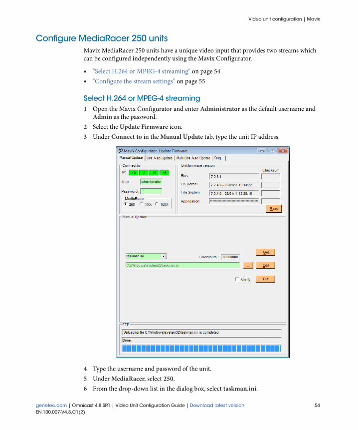
Video unit configuration | Mavix
Configure MediaRacer 250 unitsMavix MediaRacer 250 units have a unique video input that provides two streams which can be configured independently using the Mavix Configurator.
• "Select H.264 or MPEG-4 streaming" on page 54• "Configure the stream settings" on page 55
Select H.264 or MPEG-4 streaming1 Open the Mavix Configurator and enter Administrator as the default username and
Admin as the password.2 Select the Update Firmware icon.3 Under Connect to in the Manual Update tab, type the unit IP address.
4 Type the username and password of the unit.5 Under MediaRacer, select 250.6 From the drop-down list in the dialog box, select taskman.ini.
genetec.com | Omnicast 4.8 SR1 | Video Unit Configuration Guide | Download latest version 54EN.100.007-V4.8.C1(2)

Video unit configuration | Mavix
7 Click Get > Edit. The file opens in Notepad.
8 In the Video section, change the Coding= value to: Coding=8 if you want to stream H.264. Coding=5 if you want to stream MPEG-4.
9 Save the file, and click Put in the Manual Update tab.
Configure the stream settings1 Open the Mavix Configurator and enter Administrator as the default username and
Admin as the password.2 Click the Configure icon.3 In List A, select the MediaRacer 250 unit to configure.4 Click the Video tab.5 Click the Stream 1 tab, and configure the video stream settings as required.6 Click the Stream 2 tab, and configure the video stream settings as required.7 Click the OSD tab, and configure the On Screen Display text settings as required.8 Click Apply.
55 genetec.com | Omnicast 4.8 SR1 | Video Unit Configuration Guide | Download latest versionEN.100.007-V4.8.C1(2)

Video unit configuration | OTN
OTN
This section describes the additional configuration steps required for some OTN units to work in Omnicast.
Configuring MVIDIPv4 unitsDue to specific OTN MVIDIPv4 unit behavior, proper reception and decoding of the MPEG-4 video stream requires extra configuration to work in Omnicast. This configuration is done using the Registry Editor.
Disable IGMPv3 support
Because MVIDIPv4 units use a different IP address than the control channel, video streams are filtered out of potential multicast sources by the IGMPv3 protocol. For proper reception of MVIDIPv4 video streams, you must disable the IGMPv3 advanced setting on the Directory and Archiver Server machines.
1 Open the Registry Editor in Windows.2 Navigate to one of the following folders:
If you are using a 32-bit system: HKEY_LOCAL_MACHINE\SOFTWARE\Gene-tec\Genetec Omnicast4.x.
If you are using a 64-bit system: Computer\HKEY_LOCAL_MACHINE\SOFT-WARE\Wow6432Node\Genetec\Genetec Omnicast4.x.
Double-click the IGMPv3Enabled REG-DWORD.
3 In the Value data field, type 0.4 Click OK.5 Restart Omnicast services to apply your changes.
Enable MPEG-4 start code lookup offset
MVIDIPv4 units sometimes develop offset start codes in the MPEG-4 video stream. As a solution, the MPEG-4 start code lookup value must be increased so that the video stream
genetec.com | Omnicast 4.8 SR1 | Video Unit Configuration Guide | Download latest version 56EN.100.007-V4.8.C1(2)

Video unit configuration | OTN
will be found in Omnicast. This advanced setting must be modified on the Client and Server machines for proper archiving and video decoding.
1 Open the Registry Editor in Windows.2 Navigate to one of the following folders:
If you are using a 32-bit system: HKEY_LOCAL_MACHINE\SOFTWARE\Gene-tec\Genetec Omnicast4.x.
If you are using a 64-bit system: Computer\HKEY_LOCAL_MACHINE\SOFT-WARE\Wow6432Node\Genetec\Genetec Omnicast4.x.
3 Double-click the Mpeg4DemuxStartCodeLookupOffset REG_DWORD.4 In the Value data field, type 100.
This changes the start code value for video frames to have a lookup of 100 bytes, in case the offset increases with time.
5 Click OK.6 Restart Omnicast services to apply your changes.
57 genetec.com | Omnicast 4.8 SR1 | Video Unit Configuration Guide | Download latest versionEN.100.007-V4.8.C1(2)

Video unit configuration | Panasonic
Panasonic
This section describes additional information about how some Panasonic units work in Omnicast.
• "Configuring capture resolutions" on page 58• "Configuring edge analytics for WJ-NT314 units" on page 58• "Configuring I/O pins" on page 58• "Use auto-pan with Panasonic units" on page 59
Configuring capture resolutionsTo change the capture resolution for a Panasonic megapixel camera (1.3 MP or 3.0 MP), you must do it on the unit’s Web page, and then restart the unit in Omnicast to apply your changes.
Configuring edge analytics for WJ-NT314 unitsTo use edge analytics with Panasonic WJ-NT314 encoders, it must be configured for each active channel using the unit’s Web page.
Configuring I/O pinsPanasonic units DG-NS202, WV-NS954, WV-NW964, WV-NP502, and WV-NW502S do not have a hardwired pin configuration. The input and output pins cannot be configured for these units through their Web page, because Omnicast will enforce the following configuration:
NOTE Panasonic pin types other than input/output, such as auxiliary pins, are not supported in Omnicast.
Configuring WV-SC385 (DG-SC385) unitsBefore adding Panasonic WV-SC385 (DG-SC385) units to the Archiver, make sure the multicast/unicast port number is in between 1024-50000, inclusively.
Pin # Panasonic description Omnicast pin configuration
1 Alarm In IN
2 Alarm In/Alarm Out OUT
3 Alarm In/Auxiliary Out IN
4 Ground Ground
genetec.com | Omnicast 4.8 SR1 | Video Unit Configuration Guide | Download latest version 58EN.100.007-V4.8.C1(2)
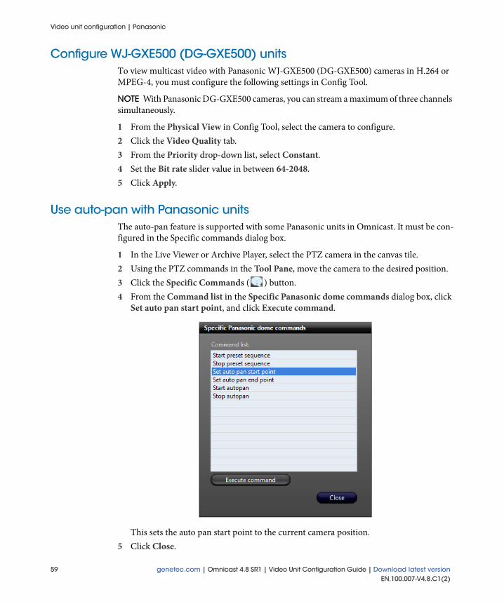
Video unit configuration | Panasonic
Configure WJ-GXE500 (DG-GXE500) unitsTo view multicast video with Panasonic WJ-GXE500 (DG-GXE500) cameras in H.264 or MPEG-4, you must configure the following settings in Config Tool.
NOTE With Panasonic DG-GXE500 cameras, you can stream a maximum of three channels simultaneously.
1 From the Physical View in Config Tool, select the camera to configure.2 Click the Video Quality tab.3 From the Priority drop-down list, select Constant.4 Set the Bit rate slider value in between 64-2048.5 Click Apply.
Use auto-pan with Panasonic unitsThe auto-pan feature is supported with some Panasonic units in Omnicast. It must be con-figured in the Specific commands dialog box.
1 In the Live Viewer or Archive Player, select the PTZ camera in the canvas tile.2 Using the PTZ commands in the Tool Pane, move the camera to the desired position.3 Click the Specific Commands ( ) button.4 From the Command list in the Specific Panasonic dome commands dialog box, click
Set auto pan start point, and click Execute command.
This sets the auto pan start point to the current camera position.5 Click Close.
59 genetec.com | Omnicast 4.8 SR1 | Video Unit Configuration Guide | Download latest versionEN.100.007-V4.8.C1(2)

Video unit configuration | Panasonic
6 To select an auto pan stop point, move the camera to the desired stopping point, and click Specific Commands ( ) button.
7 In the Specific Panasonic dome commands dialog box, click Set auto pan stop point, and click Execute command.NOTE The auto pan feature does not support tilt commands.
8 Click Start autopan, and click Execute command.The camera pans between the two points you configured.NOTE When the camera is panning, clicking another PTZ command cancels the autopan. The only exceptions are the Zoom commands.
9 To stop the auto pan, click Stop autopan, and click Execute command.10 Click Close.
genetec.com | Omnicast 4.8 SR1 | Video Unit Configuration Guide | Download latest version 60EN.100.007-V4.8.C1(2)

Video unit configuration | Pelco
Pelco
This section describes the additional configuration steps required for some Pelco units to work in Omnicast.
This section includes the following topics:
• "Configuring motion detection" on page 61• "Adding NET54xx encoder series" on page 61• "Configuring dual-streaming for Pelco IP series" on page 61• "Configuring NET5301T units" on page 61
Configuring motion detectionBest practice: When using H.264 motion detection with Pelco units, it is recommended that you disable all automatic image adjustments on the unit’s Web page.
Adding NET54xx encoder seriesThe NET54xx encoder series can have a range of one to four channels. Each channel must have a different IP address. Therefore, units like the NET5402T which have two channels, must be added twice in Omnicast, once for each IP address.
Configuring dual-streaming for Pelco IP seriesWhen using dual-streaming with Pelco IP series units, the video stream settings for each stream are linked. For example, the video settings you define for the primary stream tab (MPEG-4-1) are automatically applied in the secondary stream tab (MPEG-4-2).
Configuring NET5301T unitsNo serial port entity is created for Pelco NET5301T units in Omnicast. Therefore, to configure the serial port and enable PTZ, you must use the Specific Settings tab in the Config Tool.
61 genetec.com | Omnicast 4.8 SR1 | Video Unit Configuration Guide | Download latest versionEN.100.007-V4.8.C1(2)

Video unit configuration | Samsung
Samsung
This section describes the additional configuration steps required for some Samsung units to work in Omnicast.
This section includes the following topics:
• "Configure SNP-3750 units" on page 62• "Configure Samsung ONVIF SNV-5080 units" on page 62
Configure SNP-3750 unitsTo configure the video stream resolution for SNP-3750 units using either MPEG-4 or MJPEG streaming:
1 Open the unit’s Web page.2 Click Video Setup > Streaming.3 Choose the desired resolution from the Unicast Image Resolution drop-down list.If using MJPEG streaming, you must also modify the video resolution on the machine that is running the Config Tool.4 On the Config Tool machine, navigate to the SNP-3750 cam file, located in: C:\Program
Files\Common Files\DVR Software 4.x\Extensions\Cam Files\Samsung SNP3750.cam on 32-bit machines, and C:\Program Files (x86)\Common Files\DVR Software 4.x\Extensions\Cam Files\Samsung SNP3750.cam on 64-bit machines.
5 Open the SNP3750.cam file in Notepad.6 Locate the following line:
<MjpegURLs>public/video.cgi?ch=1&resolution=cif</MjpegURLs>
7 Replace cif with the desired resolution: qcif, cif, or 4cif.NOTE Use lowercase text only.
8 If the unit is already part of your Omnicast system, remove and delete the unit from Omnicast, and add it using the Config Tool station where the cam file has been modi-fied.
Configure Samsung ONVIF SNV-5080 unitsFor SNV-5080 Samsung ONVIF units to stream at a proper frame rate in Omnicast, the Email/FTP profile feature on the video stream being used must be disabled in the unit's Web page.
1 Open the unit’s Web page.2 In the Setup menu, navigate to the Video Profile page.3 In the Video Profile page, create a new video profile.
genetec.com | Omnicast 4.8 SR1 | Video Unit Configuration Guide | Download latest version 62EN.100.007-V4.8.C1(2)

Video unit configuration | Sanyo
For example, if you are streaming in MJPEG, create a new MJPEG profile in one of the ten empty Video Profile slots.
4 For the new video profile, select the Email/FTP profile option.5 For all other default video profiles used in Omnicast (MJPEG, MPEG-4, and H.264),
deselect the Email/FTP profile option.
Sanyo
This section describes the additional configuration steps required for some Sanyo, and Sanyo ONVIF compliant units to work in Omnicast.
This section includes the following topics:
• "Configure VCC-HD5X00 units" on page 63• "Add Sanyo ONVIF units" on page 63
Configure VCC-HD5X00 unitsYour unit must have two video streams that are configured before adding the unit to the Archiver.
1 Open the unit’s Web page.2 Click on VIDEO/AUDIO.3 Under STREAM, set STREAM 1 to H.264, and STREAM 2 to JPEG.
Add Sanyo ONVIF unitsFor Sanyo ONVIF compliant units to work in Omnicast, specific Manufacturer and HTTP port settings are required when the units are added in the Config Tool.
1 In the Physical view of the Config Tool, click the Create button. 2 Click Video Unit to open the Add a unit dialog box.3 Select the desired Archiver.4 In the Manufacturer field, select Sanyo.5 In the Unit Type field, select ONVIF.6 Enter the appropriate IP address.7 In the HTTP port field, enter 8080.8 Enter the appropriate username and password, and click Add.
63 genetec.com | Omnicast 4.8 SR1 | Video Unit Configuration Guide | Download latest versionEN.100.007-V4.8.C1(2)

Video unit configuration | Sony
Sony
This section describes the additional configuration steps required for some Sony unit features to work in Omnicast.
• "Creating Sony PTZ patterns" on page 64• "Using the Copy configuration tool" on page 67• "Configure Sony SNC-RZ30N cameras" on page 67
Creating Sony PTZ patternsPTZ patterns can be created for some Sony cameras through the Preset Tour feature. A Sony Preset Tour is similar to an Omnicast PTZ pattern; it is a series of presets (which includes camera positioning, iris, and focus settings), which can be run in the Live Viewer or Config Tool the same as any other PTZ pattern. For more information about Preset Tours, refer to your Sony camera's documentation.
There are three steps to creating Sony PTZ patterns:
• Define presets
• Configure the preset tour
• Test the Sony PTZ pattern
Define presets
You must define two or more PTZ presets on the Sony camera before you can create a pre-set tour in the unit's Web page. There are two ways to define presets:
1 Define presets in the Live Viewer:a In the Live Viewer, select the Sony PTZ camera to configure.b From the Preset drop-down list in the Tool pane, select a preset number.c Using the PTZ controls, move the camera to a new position.
d Click the Set button.2 Define presets in the Config Tool:
a In the Config Tool, select the Sony PTZ motor to configure.b Click the Test tab.c From the Preset drop-down list, select a preset number.d To view the current position of the camera, click the Live Video button.e Using the PTZ controls, move the camera to a new position.
The position of the camera changes in the Live Video window.
f Click the Set button.
genetec.com | Omnicast 4.8 SR1 | Video Unit Configuration Guide | Download latest version 64EN.100.007-V4.8.C1(2)

Video unit configuration | Sony
g Repeat Step c to Step f for each preset you want to create.
Configure the preset tour
Once you have defined two or more PTZ presets in Omnicast, you must create and config-ure a preset tour in the Sony unit’s Web page.
1 Open the Sony unit's Web page.2 Click Setting.3 Enter username and password of the unit.4 Click Preset position >Tour.
5 Set the Tour option to On.6 Select the preset tour you want to configure (A, B, C, D, or E), and set the Tour to On.7 Under Sequence in the drop-down list, select a previously defined preset you created in
Config Tool, and click Add.8 Repeat Step 7 for each preset you want to add to the sequence.9 To change the order of the presets, select a preset under Sequence, and click the Up or
Down button.10 Set the Resume time on inactivity option to On, and type a value (in seconds).
65 genetec.com | Omnicast 4.8 SR1 | Video Unit Configuration Guide | Download latest versionEN.100.007-V4.8.C1(2)

Video unit configuration | Sony
NOTE The Resume time on inactivity option is how much time it takes to resume a PTZ pattern after an operator has moved the PTZ camera. If the option is set to Off, the PTZ pattern must be restarted manually.
Best practice: Set the value to 120 seconds.11 Click OK.
You now can use the preset tour (sequence) as a PTZ pattern in Omnicast.
Test the Sony PTZ pattern
There are two ways to test a PTZ pattern:
1 Test the PTZ pattern in the Live Viewer.a In the Live Viewer, double-click the Sony PTZ camera to be tested.b From the Pattern drop-down list in the Tool Pane, select a pattern to play.
NOTE Pattern 0 in Omnicast represents preset tour A on the Sony unit, 1=B, 2=C, 3=D, and 4=E.
c Click the Play button.2 Test the PTZ pattern in the Config Tool.
a In the Config Tool, select the Sony PTZ motor to configure.b Click the Test tab.c To view the current position of the camera, click the Live Video button.d From the Pattern drop-down list, select a pattern to play.
NOTE Pattern 0 in Omnicast represents preset tour A on the Sony unit, 1=B, 2=C, 3=D, and 4=E.
e Click the Play button.
genetec.com | Omnicast 4.8 SR1 | Video Unit Configuration Guide | Download latest version 66EN.100.007-V4.8.C1(2)

Video unit configuration | Sony
Using the Copy configuration toolWhen using the Copy configuration tool in Omnicast with Sony 5th Generation units, the camera configuration is dependant on the unit configuration. Therefore, you must copy the unit configuration before copying the camera configuration.
Configure Sony SNC-RZ30N camerasTo control the PTZ speed of Sony SNC-RZ30N cameras, you need to turn the Pan-Tilt Speed command off in Config Tool.
1 From the Physical view in Config Tool, select the PTZ motor to configure.2 Click the Test tab.3 Click Specific Commands ( ) button.4 From the Command list in the Specific dome commands dialog box, click Auto pan/
tilt speed off, and click Execute command.
5 Click Close.
67 genetec.com | Omnicast 4.8 SR1 | Video Unit Configuration Guide | Download latest versionEN.100.007-V4.8.C1(2)

Video unit configuration | UDP
UDP
Complete the following configuration steps before adding UDP units to the Archiver:
1 Open the unit’s Web page.2 Click Basic Configuration tab > Web Server.3 Under HTTP(S) Settings, select the HTTP option and click Apply.
IMPORTANT If this option is not enabled, automatic unit discovery will not work in Omnicast.
4 Click the Video & Audio tab, and select Codec.5 Under Video Stream Codec Settings, click the First Stream tab and select H.264 from
the Video Codec list, then click Apply.6 Click the Second Stream tab, and select MPEG4 from the Video Codec list, then click
Apply.7 Click the System Options tab, and select RTSP/RTP.8 Select the Does not include NAL unit header option.9 Click the UNICAST tab, and select Enable RTP Session.10 Under RTP Configuration-first stream, make sure the Session name parameter dis-
plays firststream.11 Under RTP Configuration-second stream, make sure the Session name parameter
displays secondstream.12 Click Apply.
genetec.com | Omnicast 4.8 SR1 | Video Unit Configuration Guide | Download latest version 68EN.100.007-V4.8.C1(2)

Video unit configuration | Verint
Verint
This section describes the additional configuration steps required for some Verint units to work in Omnicast.
Configure S1808e-A and S1816e-A unitsBy default there are four Mic In audio inputs used in Omnicast, but S1808e-A and S1816e-A units support up to eight Line In. For these units to use the Line In audio type, you must change the input type in Omnicast.
1 In the Physical View in the Config Tool, select the unit to configure.2 Expand the unit in the entity tree to view its attached devices.3 Select the microphone to be configured.4 From the Input type drop-down list in the Properties tab, select Line In.5 Click Apply to save your changes.6 For the new audio inputs to be available, restart the unit in Omnicast.
Vivotek
This section describes the additional configuration steps required for some Vivotek units to work in Omnicast.
Configure IP8161 unitsTo stream video at 30 frames per second with Vivotek IP8161 units, you must perform additional configuration steps in the unit’s Web page.
1 Open the unit’s Web page.2 Click Configuration > Video/Audio.3 On the Video and Audio Settings page, select Stream 1, and click Change.4 From the Priority drop-down list in the Stream 1 dialog box, select Frame Rate.5 Click Set.
69 genetec.com | Omnicast 4.8 SR1 | Video Unit Configuration Guide | Download latest versionEN.100.007-V4.8.C1(2)